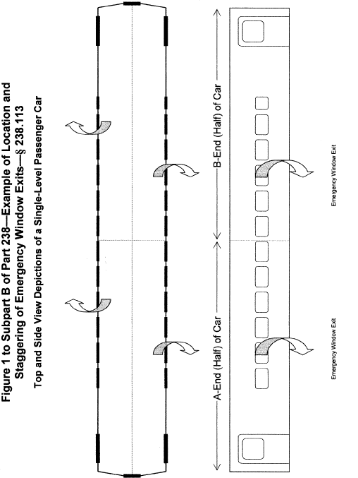
Figure 1 to Subpart B of Part 238 - Example of Location and Staggering of Emergency Window Exits - § 238.113
49:4.1.1.1.32.2.131.21.71 :
Figure 1 to Subpart B of Part 238 - Example of Location and
Staggering of Emergency Window Exits - § 238.113
[73 FR 6403, Feb.
1, 2008]
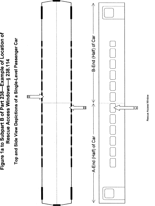
Figure 1A to Subpart B of Part 238 - Example of Location of Rescue Access Windows - § 238.114
49:4.1.1.1.32.2.131.21.72 :
Figure 1A to Subpart B of Part 238 - Example of Location of Rescue
Access Windows - § 238.114
[73 FR 6403, Feb.
1, 2008]
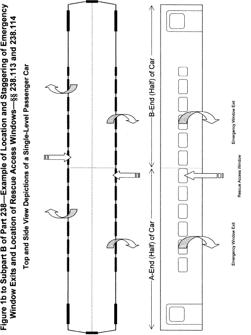
Figure 1B to Subpart B of Part 238 - Example of Location and Staggering of Emergency Window Exits and Location of Rescue Access Windows - §§ 238.113 and 238.114
49:4.1.1.1.32.2.131.21.73 :
Figure 1B to Subpart B of Part 238 - Example of Location and
Staggering of Emergency Window Exits and Location of Rescue Access
Windows - §§ 238.113 and 238.114
[73 FR 6403, Feb.
1, 2008]
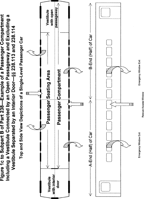
Figure 1C to Subpart B of Part 238 - Example of a Passenger Compartment Including a Vestibule Connected by an Open Passageway and Excluding a Vestibule Separated by an Interior Door - §§ 238.113 and 238.114
49:4.1.1.1.32.2.131.21.74 :
Figure 1C to Subpart B of Part 238 - Example of a Passenger
Compartment Including a Vestibule Connected by an Open Passageway
and Excluding a Vestibule Separated by an Interior Door - §§
238.113 and 238.114
[73 FR 6403, Feb.
1, 2008]
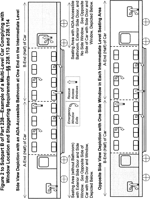
Figure 2 to Subpart B of Part 238 - Example of a Multi-Level Car Complying with Window Location and Staggering Requirements - §§ 238.113 and 238.114
49:4.1.1.1.32.2.131.21.75 :
Figure 2 to Subpart B of Part 238 - Example of a Multi-Level Car
Complying with Window Location and Staggering Requirements - §§
238.113 and 238.114
[73 FR 6403, Feb.
1, 2008]
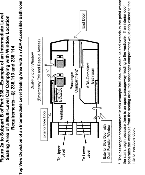
Figure 2A to Subpart B of Part 238 - Example of an Intermediate Level Seating Area of a Multi-Level Car Complying With Window Location Requirements - §§ 238.113 and 238.114
49:4.1.1.1.32.2.131.21.76 :
Figure 2A to Subpart B of Part 238 - Example of an Intermediate
Level Seating Area of a Multi-Level Car Complying With Window
Location Requirements - §§ 238.113 and 238.114
[73 FR 6403, Feb.
1, 2008]
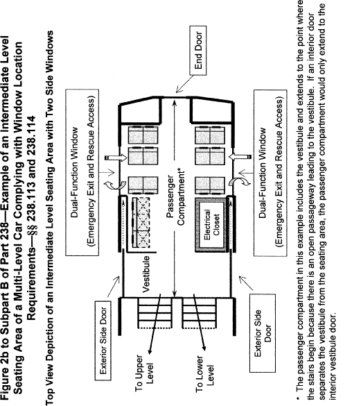
Figure 2B to Subpart B of Part 238 - Example of an Intermediate Level Seating Area of a Multi-Level Car Complying With Window Location Requirements - §§ 238.113 and 238.114
49:4.1.1.1.32.2.131.21.77 :
Figure 2B to Subpart B of Part 238 - Example of an Intermediate
Level Seating Area of a Multi-Level Car Complying With Window
Location Requirements - §§ 238.113 and 238.114
[73 FR 6403, Feb.
1, 2008]
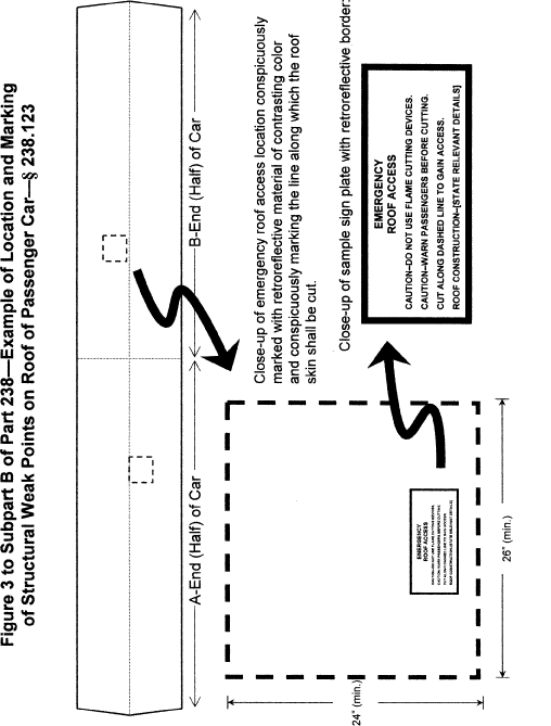
Figure 3 to Subpart B of Part 238 - Example of Location and Marking of Structural Weak Points on Roof of Passenger Car - § 238.123
49:4.1.1.1.32.2.131.21.78 :
Figure 3 to Subpart B of Part 238 - Example of Location and Marking
of Structural Weak Points on Roof of Passenger Car - § 238.123
[73 FR
6403, Feb. 1, 2008]
Figure 1 to Subpart C of Part 238
49:4.1.1.1.32.3.131.21.79 :
Figure 1 to Subpart C of Part 238
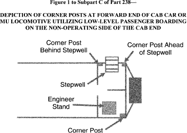
[75 FR 1230, Jan.
8, 2010]
Figure 1 to Subpart E of Part 238 - Power Car Cab Forward End Structure Conceptual Implementation
49:4.1.1.1.32.5.131.26.80 :
Figure 1 to Subpart E of Part 238 - Power Car Cab Forward End
Structure Conceptual Implementation
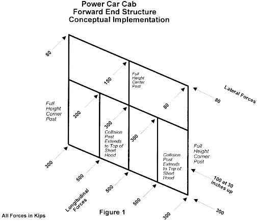
Figure 2 to Subpart E of Part 238 - Power Car Cab Rear End Structure Conceptual Implementation 1 - to Subpart E
49:4.1.1.1.32.5.131.26.81 :
Figure 2 to Subpart E of Part 238 - Power Car Cab Rear End
Structure Conceptual Implementation 1 - to Subpart E
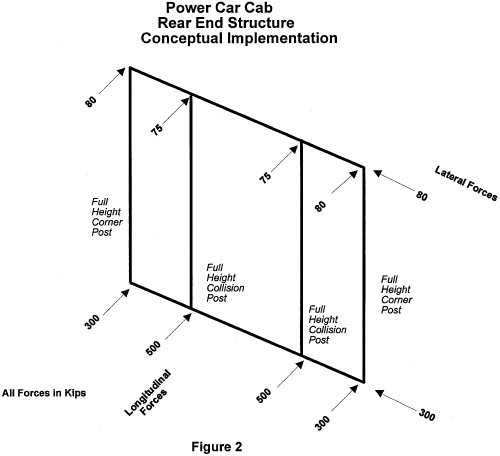
Figure 3 to Subpart E of Part 238 - Trailer Car End Structure Conceptual Implementation 1 - to Subpart E
49:4.1.1.1.32.5.131.26.82 :
Figure 3 to Subpart E of Part 238 - Trailer Car End Structure
Conceptual Implementation 1 - to Subpart E
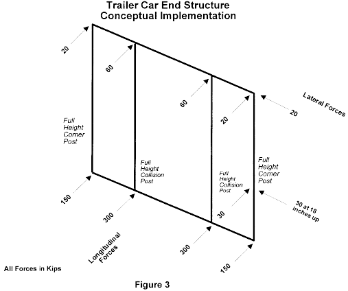
Figure 4 to Subpart E of Part 238 - Trailer Car In-Board Vestibule End Structure Conceptual Implementation 1 - to Subpart E
49:4.1.1.1.32.5.131.26.83 :
Figure 4 to Subpart E of Part 238 - Trailer Car In-Board Vestibule
End Structure Conceptual Implementation 1 - to Subpart E
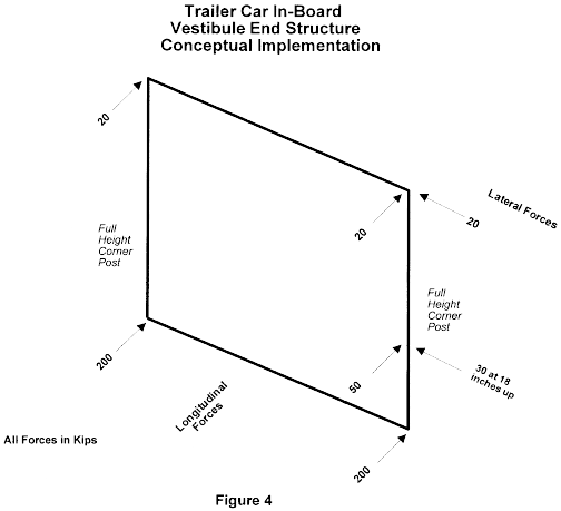
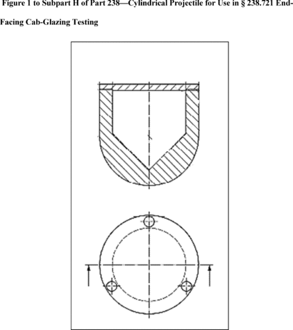
Figure 1 to Subpart H of Part 238
49:4.1.1.1.32.8.137.20.84 :
Figure 1 to Subpart H of Part 238
Appendix A to Part 238 [Reserved]
49:4.1.1.1.32.11.137.1.85 : Appendix A
Appendix A to Part 238 [Reserved]
Appendix B to Part 238 - Test Methods and Performance Criteria for the Flammability and Smoke Emission Characteristics of Materials Used in Passenger Cars and Locomotive Cabs
49:4.1.1.1.32.11.137.1.86 : Appendix B
Appendix B to Part 238 - Test Methods and Performance Criteria for
the Flammability and Smoke Emission Characteristics of Materials
Used in Passenger Cars and Locomotive Cabs
This appendix contains the test methods and performance criteria
for the flammability and smoke emission characteristics of
materials used in passenger cars and locomotive cabs, in accordance
with the requirements of § 238.103.
(a) Incorporation by reference. Certain documents are
incorporated by reference into this appendix with the approval of
the Director of the Federal Register in accordance with 5 U.S.C.
552(a) and 1 CFR part 51. You may inspect a copy of each document
during normal business hours at the Federal Railroad
Administration, Docket Clerk, 1200 New Jersey Avenue, SE.,
Washington, DC 20950 or at the National Archives and Records
Administration (NARA). For information on the availability of this
material at NARA, call 202-741-6030, or go to:
http://www.archives.gov/federal_register/code_of_federal_regulations/ibr_locations.html.
The documents incorporated by reference into this appendix and the
sources from which you may obtain these documents are listed
below:
(1) American Society for Testing and Materials (ASTM), 100 Barr
Harbor Dr., West Conshohocken, PA 19428-2959.
(i) ASTM C 1166-00, Standard Test Method for Flame Propagation
of Dense and Cellular Elastomeric Gaskets and Accessories.
(ii) ASTM D 2724-87, Standard Test Methods for Bonded, Fused,
and Laminated Apparel Fabrics.
(iii) ASTM D 3574-95, Standard Test Methods for Flexible
Cellular Materials-Slab, Bonded, and Molded Urethane Foams.
(iv) ASTM D 3675-98, Standard Test Method for Surface
Flammability of Flexible Cellular Materials Using a Radiant Heat
Energy Source.
(v) ASTM E 119-00a, Standard Test Methods for Fire Tests of
Building Construction and Materials.
(vi) ASTM E 162-98, Standard Test Method for Surface
Flammability of Materials Using a Radiant Heat Energy Source.
(vii) ASTM E 648-00, Standard Test Method for Critical Radiant
Flux of Floor-Covering Systems Using a Radiant Heat Energy
Source.
(viii) ASTM E 662-01, Standard Test Method for Specific Optical
Density of Smoke Generated by Solid Materials.
(ix) ASTM E 1354-99, Standard Test Method for Heat and Visible
Smoke Release Rates for Materials and Products Using an Oxygen
Consumption Calorimeter.
(x) ASTM E 1537-99, Standard Test Method for Fire Testing of
Upholstered Furniture.
(xi) ASTM E 1590-01, Standard Test Method for Fire Testing of
Mattresses.
(2) General Services Administration, Federal Supply Service,
Specification Section, 470 E. L'Enfant Plaza, SW., Suite 8100,
Washington, DC, 20407. FED-STD-191A-Textile Test Method 5830,
Leaching Resistance of Cloth; Standard Method (July 20, 1978).
(3) State of California, Department of Consumer Affairs, Bureau
of Home Furnishings and Thermal Insulation, 3485 Orange Grove
Avenue, North Highlands, CA 95660-5595.
(i) California Technical Bulletin (Cal TB) 129, Flammability
Test Procedure for Mattresses for Use in Public Buildings (October,
1992).
(ii) Cal TB 133, Flammability Test Procedure for Seating
Furniture for Use in Public Occupancies (January, 1991).
(b) Definitions. As used in this appendix -
Average heat release rate (q //180) means, as defined in
ASTM E 1354-99, the average heat release rate per unit area in the
time period beginning at the time of ignition and ending 180
seconds later.
Critical radiant flux (C.R.F.) means, as defined in ASTM
E 648-00, a measure of the behavior of horizontally-mounted floor
covering systems exposed to a flaming ignition source in a graded
radiant heat energy environment in a test chamber.
Flame spread index (Is) means, as defined in ASTM E
162-98, a factor derived from the rate of progress of the flame
front (Fs) and the rate of heat liberation by the material under
test (Q), such that Is = Fs × Q.
Flaming dripping means periodic dripping of flaming
material from the site of material burning or material
installation.
Flaming running means continuous flaming material leaving
the site of material burning or material installation.
Heat release rate means, as defined in ASTM E 1354-99,
the heat evolved from a specimen per unit of time.
Specific extinction area (σf) means, as defined in ASTM E
1354-99, specific extinction area for smoke.
Specific optical density (Ds) means, as defined in ASTM E
662-01, the optical density measured over unit path length within a
chamber of unit volume, produced from a specimen of unit surface
area, that is irradiated by a heat flux of 2.5 watts/cm 2 for a
specified period of time.
Surface flammability means the rate at which flames will
travel along surfaces.
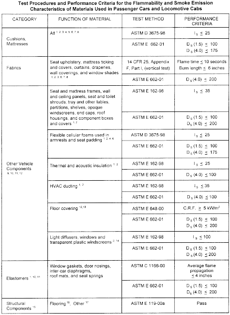
(c) Required test methods and performance criteria. The
materials used in locomotive cabs and passenger cars shall be
tested according to the methods and meet the performance criteria
set forth in the following table and notes:
1 Materials tested for surface flammability shall not exhibit
any flaming running or dripping.
2 The ASTM E 662-01 maximum test limits for smoke emission
(specific optical density) shall be measured in either the flaming
or non-flaming mode, utilizing the mode which generates the most
smoke.
3 Testing of a complete seat assembly (including cushions,
fabric layers, upholstery) according to ASTM E 1537-99 using the
pass/fail criteria of Cal TB 133, and testing of a complete
mattress assembly (including foam and ticking) according to ASTM E
1590-01 using the pass/fail criteria of Cal TB 129 shall be
permitted in lieu of the test methods prescribed herein, provided
the assembly component units remain unchanged or new (replacement)
assembly components possess equivalent fire performance properties
to the original components tested. A fire hazard analysis must also
be conducted that considers the operating environment within which
the seat or mattress assembly will be used in relation to the risk
of vandalism, puncture, cutting, or other acts which may expose the
individual components of the assemblies to an ignition source.
Notes 5, 6, 7, and 8 apply.
4 Testing is performed without upholstery.
5 The surface flammability and smoke emission characteristics
shall be demonstrated to be permanent after dynamic testing
according to ASTM D 3574-95, Test I 2 (Dynamic Fatigue Test by the
Roller Shear at Constant Force) or Test I 3 (Dynamic Fatigue Test
by Constant Force Pounding) both using Procedure B, except that the
test samples shall be a minimum of 6 inches (154 mm) by 18 inches
(457 mm) by the thickness of the material in its end use
configuration, or multiples thereof. If Test I 3 is used, the size
of the indentor described in paragraph 96.2 shall be modified to
accommodate the specified test specimen.
6 The surface flammability and smoke emission characteristics
shall be demonstrated to be permanent by washing, if appropriate,
according to FED-STD-191A Textile Test Method 5830.
7 The surface flammability and smoke emission characteristics
shall be demonstrated to be permanent by dry-cleaning, if
appropriate, according to ASTM D 2724-87.
8 Materials that cannot be washed or dry-cleaned shall be so
labeled and shall meet the applicable performance criteria after
being cleaned as recommended by the manufacturer.
9 Signage is not required to meet any flammability or smoke
emission performance criteria specified in this Appendix.
10 Materials used to fabricate miscellaneous, discontinuous
small parts (such as knobs, rollers, fasteners, clips, grommets,
and small electrical parts) that will not contribute materially to
fire growth in end use configuration are exempt from flammability
and smoke emission performance requirements, provided that the
surface area of any individual small part is less than 16 square
inches (100 cm 2) in end use configuration and an appropriate fire
hazard analysis is conducted which addresses the location and
quantity of the materials used, and the vulnerability of the
materials to ignition and contribution to flame spread.
11 If the surface area of any individual small part is less than
16 square inches (100 cm 2) in end use configuration, materials
used to fabricate such a part may be tested in accordance with ASTM
E 1354-99 as an alternative to both (a) the ASTM E 162-98
flammability test procedure, or the appropriate flammability test
procedure otherwise specified in the table, and (b) the ASTM E
662-01 smoke generation test procedure. Testing shall be at 50 kW/m
2 applied heat flux with a retainer frame. Materials tested in
accordance with ASTM E 1354-99 shall meet the following performance
criteria: average heat release rate (q // 180) less than or equal
to 100 kW/m 2, and average specific extinction area (σf) less than
or equal to 500 m 2/kg over the same 180-second period.
12 Carpeting used as a wall or ceiling covering shall be tested
according to ASTM E 162-98 and ASTM E 662-01 and meet the
respective criteria of I s less than or equal to 35 and D s (1.5)
less than or equal to 100 and D s (4.0) less than or equal to 200.
Notes 1 and 2 apply.
13 Floor covering shall be tested with padding in accordance
with ASTM E 648-00, if the padding is used in the actual
installation.
14 For double window glazing, only the interior glazing is
required to meet the requirements specified herein. (The exterior
glazing is not required to meet these requirements.)
15 Penetrations (ducts, etc.) shall be designed against acting
as passageways for fire and smoke and representative penetrations
shall be included as part of test assemblies.
16 A structural flooring assembly separating the interior of a
vehicle from its undercarriage shall meet the performance criteria
during a nominal test period as determined by the railroad. The
nominal test period must be twice the maximum expected time period
under normal circumstances for a vehicle to stop completely and
safely from its maximum operating speed, plus the time necessary to
evacuate all the vehicle's occupants to a safe area. The nominal
test period must not be less than 15 minutes. Only one specimen
need be tested. A proportional reduction may be made in the
dimensions of the specimen provided it serves to truly test the
ability of the structural flooring assembly to perform as a barrier
against under-vehicle fires. The fire resistance period required
shall be consistent with the safe evacuation of a full load of
passengers from the vehicle under worst-case conditions. For
purposes of this Note, the floor assembly of a vehicle in a Tier
III trainset may be tested together with undercar design features
that separate the vehicle from the fire source, i.e., skirts
and bottom covers, to protect against a fire source under and
external to the vehicle. To assess the safety associated with
testing the floor assembly in this manner, and to protect against a
fire source under the floor assembly but internal to the vehicle,
safety must also be demonstrated by conducting a fire hazard
analysis that includes the considerations in Note 17.
17 Portions of the vehicle body which separate major ignition
sources, energy sources, or sources of fuel-load from vehicle
interiors, shall have sufficient fire endurance as determined by a
fire hazard analysis acceptable to the railroad which addresses the
location and quantity of the materials used, as well as
vulnerability of the materials to ignition, flame spread, and smoke
generation. These portions include equipment carrying portions of a
vehicle's roof and the interior structure separating the levels of
a bi-level car, but do not include a flooring assembly subject to
Note 16. A railroad is not required to use the ASTM E 119-00a test
method.
[67 FR 42910, June 25, 2002, as amended at 74 FR 25175, May 27,
2009; 83 FR 59228, Nov. 21, 2018]
Appendix C to Part 238 [Reserved]
49:4.1.1.1.32.11.137.1.87 : Appendix C
Appendix C to Part 238 [Reserved]
Appendix D to Part 238 - Requirements for External Fuel Tanks on Tier I Locomotives
49:4.1.1.1.32.11.137.1.88 : Appendix D
Appendix D to Part 238 - Requirements for External Fuel Tanks on
Tier I Locomotives
The requirements contained in this appendix are intended to
address the structural and puncture resistance properties of the
locomotive fuel tank to reduce the risk of fuel spillage to
acceptable levels under derailment and minor collision
conditions.
(a) Structural strength - (1) Load case 1 - minor
derailment. The end plate of the fuel tank shall support a
sudden loading of one-half the weight of the car body at a vertical
acceleration of 2g, without exceeding the ultimate strength of the
material. The load is assumed to be supported on one rail, within
an eight inch band (plus or minus) at a point nominally above the
head of the rail, on tangent track. Consideration should be given
in the design of the fuel tank to maximize the vertical clearance
between the top of the rail and the bottom of the fuel tank.
(2) Load case 2 - jackknifed locomotive. The fuel tank
shall support transversely at the center a sudden loading
equivalent to one half the weight of the locomotive at a vertical
acceleration of 2g, without exceeding the ultimate strength of the
material. The load is assumed to be supported on one rail,
distributed between the longitudinal center line and the edge of
the tank bottom, with a rail head surface of two inches.
(3) Load case 3 - side impact. In a side impact collision
by an 80,000 pound Gross Vehicle Weight tractor/trailer at the
longitudinal center of the fuel tank, the fuel tank shall
withstand, without exceeding the ultimate strength, a 200,000 pound
load (2.5g) distributed over an area of six inches by forty-eight
inches (half the bumper area) at a height of thirty inches above
the rail (standard DOT bumper height).
(4) Load case 4 - penetration resistance. The minimum
thickness of the sides, bottom sheet and end plates of the fuel
tank shall be equivalent to a 5/16-inch steel plate with a 25,000
pounds-per-square-inch yield strength (where the thickness varies
inversely with the square root of yield strength). The lower one
third of the end plates shall have the equivalent penetration
resistance by the above method of a 3/4-inch steel plate with a
25,000 pounds-per-square-inch yield strength. This may be
accomplished by any combination of materials or other mechanical
protection.
(b) Sideswipe. To minimize fuel tank damage during
sideswipes (railroad vehicles and grade crossings), all drain
plugs, clean-out ports, inspection covers, sight glasses, gauge
openings, etc., must be flush with the tank surface or adequately
protected to avoid catching foreign objects or breakage. All seams
must be protected or flush to avoid catching foreign objects.
(c) Spill controls. Vents and fills shall be designed to
avert spillage of fuel in the event of a roll over.
Appendix E to Part 238 - General Principles of Reliability-Based Maintenance Programs
49:4.1.1.1.32.11.137.1.89 : Appendix E
Appendix E to Part 238 - General Principles of Reliability-Based
Maintenance Programs
(a) Any maintenance program has the following four basic
objectives:
(1) To ensure realization of the design level of safety and
reliability of the equipment;
(2) To restore safety and reliability to their design levels
when deterioration has occurred;
(3) To obtain the information necessary for design improvements
of those items whose design reliability proves inadequate; and
(4) To accomplish these goals at a minimum total cost, including
maintenance costs and the costs of residual failures.
(b) Reliability-based maintenance programs are based on the
following general principles. A failure is an unsatisfactory
condition. There are two types of failures: functional and
potential. Functional failures are usually reported by operating
crews. Conversely, maintenance crews usually discover potential
failures. A potential failure is an identifiable physical
condition, which indicates that a functional failure is imminent.
The consequences of a functional failure determine the priority of
a maintenance effort. These consequences fall into the following
general categories:
(1) Safety consequences, involving possible loss of the
equipment and its occupants;
(2) Operational consequences, which involve an indirect economic
loss as well as the direct cost of repair;
(3) Non-operational consequences, which involve only the direct
cost of repair; or
(4) Hidden failure consequences, which involve exposure to a
possible multiple failure as a result of the undetected failure of
a hidden function.
(c) In a reliability-based maintenance program, scheduled
maintenance is required for any item whose loss of function or mode
of failure could have safety consequences. If preventative tasks
cannot reduce the risk of such failures to an acceptable level, the
item requires redesign to alter its failure consequences. Scheduled
maintenance is also required for any item whose functional failure
will not be evident to the operating crew, and therefore reported
for corrective action. In all other cases the consequences of
failure are economic, and maintenance tasks directed at preventing
such failures must be justified on economic grounds. All failure
consequences, including economic consequences, are established by
the design characteristics of the equipment and can be altered only
by basic changes in the design. Safety consequences can, in nearly
all cases, be reduced to economic consequences by the use of
redundancy. Hidden functions can usually be made evident by
instrumentation or other design features. The feasibility and cost
effectiveness of scheduled maintenance depend on the
inspectablility of the component, and the cost of corrective
maintenance depends on its failure modes and design
reliability.
(d) The design reliability of equipment or components will only
be achieved with an effective maintenance program. This level of
reliability is established by the design of each component and the
manufacturing processes that produced it. Scheduled maintenance can
ensure that design reliability of each component is achieved, but
maintenance alone cannot yield a level of reliability beyond the
design reliability.
(e) When a maintenance program is developed, it includes tasks
that satisfy the criteria for both applicability and effectiveness.
The applicability of a task is determined by the characteristics of
the component or equipment to be maintained. The effectiveness is
stated in terms of the consequences that the task is designed to
prevent. The basics types of tasks that are performed by
maintenance personnel are each applicable under a unique set of
conditions. Tasks may be directed at preventing functional failures
or preventing a failure event consisting of the sequential
occurrence of two or more independent failures which may have
consequences that would not be produced by any of the failures
occurring separately. The task types include:
(1) Inspections of an item to find and correct any potential
failures;
(2) Rework/remanufacture/overhaul of an item at or before some
specified time or age limit;
(3) Discard of an item (or parts of it) at or before some
specified life limit; and
(4) Failure finding inspections of a hidden-function item to
find and correct functional failures that have already occurred but
were not evident to the operating crew.
(b) Components or systems in a reliability-based maintenance
program may be defined as simple or complex. A simple component or
system is one that is subject to only one or a very few failure
modes. This type of component or system frequently shows decreasing
reliability with increasing operating age. An age/time limit may be
used to reduce the overall failure rate of simple components or
systems. Here, safe-life limits, fail-safe designs, or damage
tolerance-based residual life calculations may be imposed on a
single component or system to play a crucial role in controlling
critical failures. Complex components or systems are ones whose
functional failure may result from many different failure modes and
show little or no decrease in overall reliability with increasing
age unless there is a dominant failure mode. Therefore, age limits
imposed on complex components or systems have little or no effect
on their overall failure rates.
(g) When planning the maintenance of a component or system to
protect the safety and operating capability of the equipment, a
number of items must be considered in the reliability assessment
process:
(1) The consequences of each type of functional failure;
(2) The visibility of a functional failure to the operating crew
(evidence that a failure has occurred);
(3) The visibility of reduced resistance to failure (evidence
that a failure is imminent);
(4) The age-reliability characteristics of each item;
(5) The economic tradeoff between the cost of scheduled
maintenance and the benefits to be derived from it;
(6) A multiple failure, resulting from a sequence of independent
failures, may have consequences that would not be caused by any one
of the individual failures alone. These consequences are taken into
account in the definition of the failure consequences for the first
failure; and
(7) A default strategy governs decision making in the absence of
full information or agreement. This strategy provides for
conservative initial decisions, to be revised on the basis of
information derived from operating experience.
(h) A successful reliability-based maintenance program must be
dynamic. Any prior-to-service program is based on limited
information. As such, the operating organization must be prepared
to collect and respond to real data throughout the operating life
of the equipment. Management of the ongoing maintenance program
requires an organized information system for surveillance and
analysis of the performance of each item under actual operating
conditions. This information is needed to determine the refinements
and modifications to be made in the initial maintenance program
(including the adjustment of task intervals) and to determine the
need for product improvement. The information derived from
operating experience may be considered to have the following
hierarchy of importance in the reliability-based maintenance
program:
(1) Failures that could affect operating safety;
(2) Failures that have operational consequences;
(3) The failure modes of units removed as a result of
failures;
(4) The general condition of unfailed parts in units that have
failed; and
(5) The general condition of serviceable units inspected as
samples.
(i) At the time an initial maintenance program is developed,
information is usually available to determine the tasks necessary
to protect safety and operating capability. However, the
information required to determine optimum task intervals and the
applicability of age or life limits can be obtained only from age
or life exploration after the equipment enters service. With any
new equipment there is always the possibility of unanticipated
failure modes. The first occurrence of any serious unanticipated
failure should immediately set into motion the following
improvement cycle:
(1) An inspection task is developed to prevent recurrences while
the item is being redesigned;
(2) The operating fleet is modified to incorporate the
redesigned part; and
(3) After the modification has proved successful, the special
inspection task is eliminated from the maintenance program.
(j) Component improvements based on identification of the actual
reliability characteristics of each item through age or life
exploration, is part of the normal development cycle of all complex
equipment.
Appendix F to Part 238 - Alternative Dynamic Performance Requirements for Front End Structures of Cab Cars and MU Locomotives
49:4.1.1.1.32.11.137.1.90 : Appendix F
Appendix F to Part 238 - Alternative Dynamic Performance
Requirements for Front End Structures of Cab Cars and MU
Locomotives
As specified in § 238.209(b), the forward end of a cab car or an
MU locomotive may comply with the requirements of this appendix in
lieu of the requirements of either § 238.211 (Collision posts) or §
238.213 (Corner posts), or both. The requirements of this appendix
are intended to be equivalent to the requirements of those sections
and allow for the application of dynamic performance criteria to
cab cars and MU locomotives as an alternative to the requirements
of those sections. The alternative dynamic performance requirements
are applicable to all cab cars and MU locomotives, and may in
particular be helpful for evaluating the compliance of cab cars and
MU locomotives with shaped-noses or crash energy management
designs, or both. In any case, the end structure must be designed
to protect the occupied volume for its full height, from the
underframe to the anti-telescoping plate (if used) or roof
rails.
The requirements of this appendix are provided only as
alternatives to the requirements of §§ 238.211 and 238.213, not in
addition to the requirements of those sections. Cab cars and MU
locomotives are not required to comply with both the requirements
of those sections and the requirements of this appendix,
together.
Although the requirements of this appendix are stated in terms
applicable to Tier I passenger equipment, they are also applicable
to Tier III passenger trainsets under § 238.711. Specifically, the
cab ends of Tier III trainsets shall comply with the requirements
of this appendix to demonstrate the integrity of the end
structure.
Alternative Requirements for Collision Posts
(a)(1) In lieu of meeting the requirements of § 238.211, the
front end frame acting together with its supporting car body
structure shall be capable of absorbing a minimum of 135,000
foot-pounds of energy (0.18 megajoule) prior to or during
structural deformation by withstanding a frontal impact with a
rigid object in accordance with all of the requirements set forth
in paragraphs (a)(2) through (a)(4) of this appendix:
(2)(i) The striking surface of the object shall be centered at a
height of 30 inches above the top of the underframe;
(ii) The striking surface of the object shall have a width of no
more than 36 inches and a diameter of no more than 48 inches;
(iii) The center of the striking surface shall be offset by 19
inches laterally from the center of the cab car or MU locomotive,
and on the weaker side of the end frame if the end frame's strength
is not symmetrical; and
(iv) Only the striking surface of the object interacts with the
end frame structure.
(3) As a result of the impact, there shall be no more than 10
inches of longitudinal, permanent deformation into the occupied
volume. There shall also be no complete separation of the post, its
connection to the underframe, its connection to either the roof
structure or the anti-telescoping plate (if used), or of its
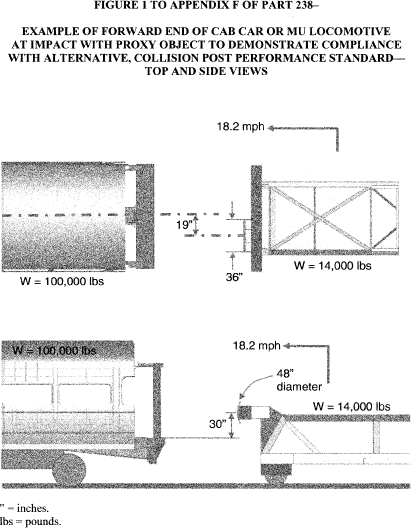
supporting car body structure. (A graphical description of the
frontal impact is provided in Figure 1 to this appendix.)
(4) The nominal weights of the object and the cab car or MU
locomotive, as ballasted, and the speed of the object may be
adjusted to impart the minimum of 135,000 foot-pounds of energy
(0.18 megajoule) to be absorbed (Ea), in accordance with the
following formula:
Ea = E0−Ef Where: E0 = Energy of initially moving object at impact
= 1/2 m1*V0 2. Ef = Energy after impact = 1/2 (m1 + m2)*Vf 2. V0 =
Speed of initially moving object at impact. Vf = Speed of both
objects after collision = m1*V0/(m1 + m2). m1 = Mass of initially
moving object. m2 = Mass of initially standing object.
(Figure 1 shows as an example a cab car or an MU locomotive
having a weight of 100,000 pounds and the impact object having a
weight of 14,000 pounds, so that a minimum speed of 18.2 mph would
satisfy the collision-energy requirement.)
Alternative Requirements for Corner Posts
(b)(1) In lieu of meeting the requirements of § 238.213, the
front end frame acting together with its supporting car body
structure shall be capable of absorbing a minimum of 120,000
foot-pounds of energy (0.16 megajoule) prior to or during
structural deformation by withstanding a frontal impact with a
rigid object in accordance with all of the requirements set forth
in paragraphs (b)(2) through (b)(4) of this appendix:
(2)(i) The striking surface of the object shall be centered at a
height of 30 inches above the top of the underframe;
(ii) The striking surface of the object shall have a width of no
more than 36 inches and a diameter of no more than 48 inches;
(iii) The center of the striking surface shall be aligned with
the outboard edge of the cab car or MU locomotive, and on the
weaker side of the end frame if the end frame's strength is not
symmetrical; and
(iv) Only the striking surface of the object interacts with the
end frame structure.
(3)(i) Except as provided in paragraph (b)(3)(ii) of this
appendix, as a result of the impact, there shall be no more than 10
inches of longitudinal, permanent deformation into the occupied
volume. There shall also be no complete separation of the post, its
connection to the underframe, its connection to either the roof
structure or the anti-telescoping plate (if used), or of its
supporting car body structure. (A graphical description of the
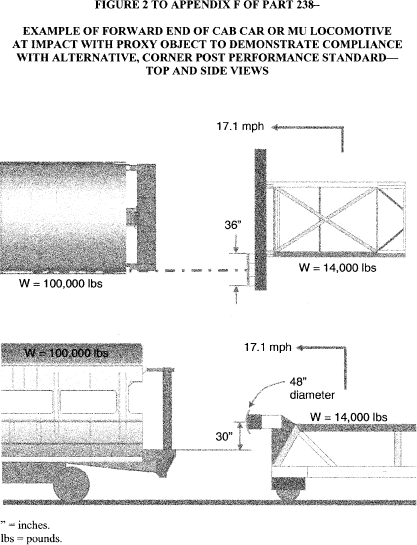
frontal impact is provided in Figure 2 to this appendix.); and
(ii) After FRA review and approval of a plan, including
acceptance criteria, to evaluate compliance with this paragraph
(b), cab cars and MU locomotives utilizing low-level passenger
boarding on the non-operating side of the cab may have two,
full-height corner posts on that side, one post located ahead of
the stepwell and one located behind it, so that the corner post
located ahead of the stepwell is permitted to fail provided that
-
(A) The corner post located behind the stepwell shall have no
more than 10 inches of longitudinal, permanent deformation; and
(B) There shall be no complete separation of that post, its
connection to the underframe, its connection to either the roof
structure or the anti-telescoping plate (if used), or of its
supporting car body structure.
(4) The nominal weights of the object and the cab car or MU
locomotive, as ballasted, and the speed of the object may be
adjusted to impart the minimum of 120,000 foot-pounds of energy
(0.16 megajoule) to be absorbed (Ea), in accordance with the
following formula:
Ea = E0−Ef Where: E0 = Energy of initially moving object at impact
= 1/2 m1*V0 2. Ef = Energy after impact = 1/2 (m1 + m2)*Vf 2. V0 =
Speed of initially moving object at impact. Vf = Speed of both
objects after collision = m1*V0/(m1 + m2). m1 = Mass of initially
moving object. m2 = Mass of initially standing object.
(Figure 2 shows as an example a cab car or an MU locomotive
having a weight of 100,000 pounds and the impact object having a
weight of 14,000 pounds, so that a minimum speed of 17.1 mph would
satisfy the collision-energy requirement.)
[75 FR 1230, Jan.
8, 2010, as amended at 83 FR 59228, Nov. 21, 2018]
Appendix G to Part 238 - Alternative Requirements for Evaluating the Crashworthiness and Occupant Protection Performance of Tier I Passenger Trainsets
49:4.1.1.1.32.11.137.1.91 : Appendix G
Appendix G to Part 238 - Alternative Requirements for Evaluating
the Crashworthiness and Occupant Protection Performance of Tier I
Passenger Trainsets General
This appendix applies to Tier I alternative passenger trainsets,
as described below. While the appendix may refer to specific units
of rail equipment in a trainset, the alternative requirements in
this appendix apply only to a trainset as a whole.
This appendix specifies alternatives to the crashworthiness and
occupant protection performance requirements for Tier I passenger
equipment in §§ 238.203, Static end strength; 238.205,
Anti-climbing mechanism; 238.207, Link between coupling mechanism
and car body; 238.209(a), Forward end structure of locomotives,
including cab cars and MU locomotives; 238.211, Collision posts;
238.213, Corner posts; and 238.219, Truck-to-carbody attachment. To
maintain their integrity, these requirements apply as a whole. They
also apply in addition to the requirements of §§ 238.209(b);
238.215, Rollover strength; 238.217, Side structure; and 238.233,
Interior fittings and surfaces; and they apply with APTA standards
for occupant protection, as specified in this appendix.
For ease of comparison with the Tier I requirements in subpart C
of this part, this appendix is arranged in order by the Tier I
section referenced.
Use of this appendix to demonstrate alternative crashworthiness
and occupant protection performance for Tier I passenger equipment
is subject to FRA review and approval under § 238.201.
Occupied Volume Integrity
(a) Instead of the requirements of § 238.203, the units of a
Tier I alternative passenger trainset may demonstrate their
occupied volume integrity by complying with both the quasi-static
compression load and dynamic collision requirements in §§
238.703(b) and 238.705, respectively.
Override Protection
(b) Colliding equipment. Instead of the requirements of §
238.205, the units of a Tier I alternative passenger trainset may
demonstrate their ability to resist vertical climbing and override
at each colliding interface during a train-to-train collision by
complying with the dynamic collision requirements in §
238.707(a).
(c) Connected equipment. Instead of the requirements of
§§ 238.205 and 238.207, when connected, the units of a Tier I
alternative passenger trainset may demonstrate their ability to
resist vertical climbing and override by complying with the dynamic
collision requirements in § 238.707(b).
Fluid Entry Inhibition
(d) Instead of the requirements of § 238.209(a), each cab end of
a Tier I alternative passenger trainset may demonstrate its ability
to inhibit fluid entry and provide other penetration resistance by
complying with the requirements in § 238.709.
End Structure Integrity of Cab End
(e) Each cab end of a Tier I alternative passenger trainset is
subject to the requirements of appendix F to this part to
demonstrate cab end structure integrity. For those cab ends without
identifiable corner or collision posts, the requirements of
appendix F to this part apply to the end structure at the specified
locations, regardless of whether the structure at the specified
locations is a post.
End Structure Integrity of Non-Cab End
(f) Instead of the applicable requirements of §§ 238.211 and
238.213, the units of a Tier I alternative trainset may demonstrate
end structure integrity for other than a cab end by complying with
the requirements in § 238.713(b) and (c).
Roof and Side Structure Integrity
(g) A Tier I alternative passenger trainset is subject to the
requirements of §§ 238.215 and 238.217 to demonstrate roof and side
structure integrity.
Truck Attachment
(h) Instead of the requirements of § 238.219, the units of a
Tier I alternative passenger trainset may demonstrate their
truck-to-carbody attachment integrity by complying with the
requirements in § 238.717 (b) through (e).
Interior Fixture Attachment
(i)(1) A Tier I alternative passenger trainset is subject to the
interior fixture requirements in § 238.233. Interior fixtures must
also comply with APTA PR-CS-S-006-98, Rev. 1, “Standard for
Attachment Strength of Interior Fittings for Passenger Railroad
Equipment,” Authorized September 28, 2005, and those portions of
APTA PR-CS-S-034-99, Rev. 2, “Standard for the Design and
Construction of Passenger Railroad Rolling Stock,” Authorized June
11, 2006, relating to interior fixtures.
(2) The standards required in this paragraph (i) are
incorporated by reference into this paragraph with the approval of
the Director of the Federal Register under 5 U.S.C. 552(a) and 1
CFR part 51. All approved material is available for inspection at
Federal Railroad Administration, Docket Clerk, 1200 New Jersey
Avenue SE, Washington, DC and available from the American Public
Transportation Association, 1666 K Street NW, Washington, DC 20006,
www.aptastandards.com. It is also available for inspection
at the National Archives and Records Administration (NARA). For
information on the availability of this material at NARA, call
202-741-6030 or go to
www.archives.gov/federal-register/cfr/ibr-locations.html.
(i) APTA PR-CS-S-006-98, Rev. 1, “Standard for Attachment
Strength of Interior Fittings for Passenger Railroad Equipment,”
Authorized September 28, 2005.
(ii) APTA PR-CS-S-034-99, Rev. 2, “Standard for the Design and
Construction of Passenger Railroad Rolling Stock,” Authorized June
11, 2006.
Seat Crashworthiness (Passenger and Crew)
(j) Passenger seating. (1) Passenger seating in a Tier I
alternative passenger trainset is subject to the requirements for
seats in § 238.233 and must also comply with APTA PR-CS-S-016-99,
Rev. 2, “Standard for Passenger Seats in Passenger Rail Cars,”
Authorized October 3, 2010, with the exception of Section 6, “Seat
durability testing.”
(2) APTA PR-CS-S-016-99, Rev. 2, “Standard for Passenger Seats
in Passenger Rail Cars,” Authorized October 3, 2010, is
incorporated by reference into this paragraph (j) with the approval
of the Director of the Federal Register under 5 U.S.C. 552(a) and 1
CFR part 51. All approved material is available for inspection at
Federal Railroad Administration, Docket Clerk, 1200 New Jersey
Avenue SE, Washington, DC and is available from the American Public
Transportation Association, 1666 K Street NW, Washington, DC 20006,
www.aptastandards.com. It is also available for inspection
at the National Archives and Records Administration (NARA). For
information on the availability of this material at NARA, call
202-741-6030 or go to
www.archives.gov/federal-register/cfr/ibr-locations.html.
(k) Crew seating. Each seat provided for an employee
regularly assigned to occupy the cab of a Tier I alternative
passenger trainset, and any floor-mounted seat in the cab, must
comply with § 238.233(e), (f), and (g).
[83 FR 59228, Nov. 21, 2018]
Appendix H to Part 238 - Rigid Locomotive Design Computer Model Input Data and Geometrical Depiction
49:4.1.1.1.32.11.137.1.92 : Appendix H
Appendix H to Part 238 - Rigid Locomotive Design Computer Model
Input Data and Geometrical Depiction
(a) As specified in § 238.705(a)(4), this appendix provides
input data and a geometrical depiction necessary to create a
computer model of the rigid locomotive design for use in evaluating
the occupied volume integrity of a Tier III trainset in a dynamic
collision scenario. (This appendix may also be applied to a Tier I
alternative passenger trainset to evaluate its occupied volume
integrity, in accordance with appendix G to this part).
(b) The input data, in the form of an input file, contains the
geometry for approximately the first 12 feet of the rigid
locomotive design. Because this input file is for a half-symmetric
model, a locomotive mass corresponding to 130,000 pounds of weight
is provided for modeling purposes - half the 260,000 pounds of
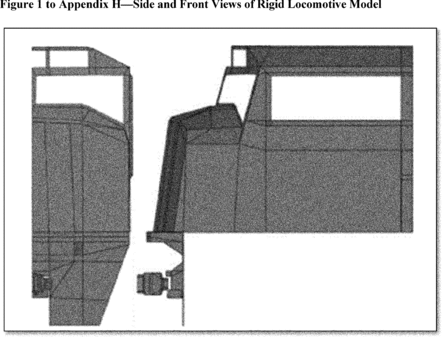
weight specified for the locomotive in § 238.705(a)(4). Figure 1 to
this appendix provides two views of the locomotive's geometric
depiction. The input data is contained in Appendix C to FRA's
Technical Criteria and Procedures Report, available at
http://www.fra.dot.gov/eLib/details/L01292#p4_z50_gD_lRT.
[83 FR
59229, Nov. 21, 2018]