Title 49
SECTION 572.35
572.35 Limbs.
§ 572.35 Limbs.(a) The limbs consist of the following assemblies: leg assemblies 86-5001-001, revision A and -002, revision A, and arm assemblies 78051-123, revision D and -124, revision D, and shall conform to the drawings subtended therein.
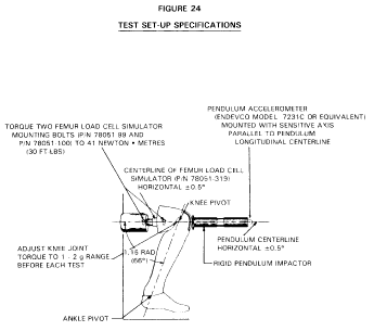
(b) Femur impact response. (1) When each knee of the leg assemblies is impacted in accordance with paragraph (b)(2) of this section, at 6.9 ft/sec ±0.10 ft/sec by the pendulum defined in § 572.36(b), the peak knee impact force, which is a product of pendulum mass and acceleration, shall have a minimum value of not less than 1060 pounds and a maximum value of not more than 1300 pounds.
(2) Test procedure. (i) The test material consists of leg assemblies (86-5001-001, revision A) left and (-002, revision A) right with upper leg assemblies (78051-46) left and (78051-47) right removed. The load cell simulator (78051-319, revision A) is used to secure the knee cap assemblies (79051-16, revision B) as shown in Figure 24.
(ii) Soak the test material in a test environment at any temperature between 66 degrees F to 78 degrees F and at a relative humidity from 10% to 70% for a period of at least four hours prior to its application in a test.
(iii) Mount the test material with the leg assembly secured through the load cell simulator to a rigid surface as shown in Figure 24. No contact is permitted between the foot and any other exterior surfaces.
(iv) Place the longitudinal centerline of the test probe so that at contact with the knee it is collinear within 2 degrees with the longitudinal centerline of the femur load cell simulator.
(v) Guide the pendulum so that there is no significant lateral, vertical or rotational movement at time zero.
(vi) Impact the knee with the test probe so that the longitudinal centerline of the test probe at the instant of impact falls within .5 degrees of a horizontal line parallel to the femur load cell simulator at time zero.
(vii) Time zero is defined as the time of contact between the test probe and the knee.
(c) Hip joint-femur flexion. (1) When each femur is rotated in the flexion direction in accordance with paragraph (c)(2) of this section, the femur torque at 30 deg. rotation from its initial horizontal orientation will not be more than 70 ft-lbf, and at 150 ft-lbf of torque will not be less than 40 deg. or more than 50 deg.
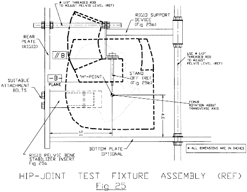
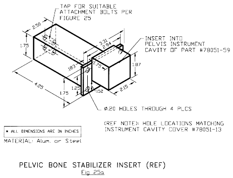
(2) Test procedure. (i) The test material consists of the assembled dummy, part No. 78051-218 (revision S) except that (1) leg assemblies (86-5001-001 and 002) are separated from the dummy by removing the 3/8-16 Socket Head Cap Screw (SHCS) (78051-99) but retaining the structural assembly of the upper legs (78051-43 and -44), (2) the abdominal insert (78051-52) is removed and (3) the instrument cover plate (78051-13) in the pelvic bone is replaced by a rigid pelvic bone stabilizer insert (Figure 25a) and firmly secured.
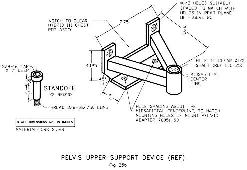
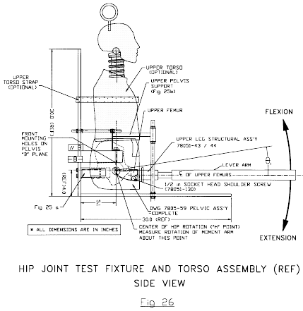
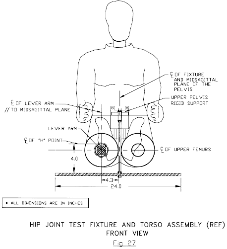
(ii) Seat the dummy on a rigid seat fixture (Figure 25) and firmly secure it to the seat back by bolting the stabilizer insert and the rigid support device (Figure 25b) to the seat back of the test fixture (Figures 26 and 27) while maintaining the pelvis (78051-58) “B” plane horizontal.
(iii) Insert a lever arm into the femur shaft opening of the upper leg structure assembly (78051-43/44) and firmly secure it using the 3/8-16 socket head cap screws.
(iv) Lift the lever arm parallel to the midsagittal plane at a rotation rate of 5 to 10 deg. per second while maintaining the 1/2 in. shoulder bolt longitudinal centerline horizontal throughout the range of motion until the 150 ft-lbf torque level is reached. Record the torque and angle of rotation of the femur.
(v) Operating environment and temperature are the same as specified in paragraph (b)(2)(ii) of this section.
 [51 FR 26701, July
25, 1986, as amended at 53 FR 8765, Mar. 17, 1988; 61 FR 67955,
Dec. 26, 1997; 63 FR 5748, Feb. 4, 1998]