Title 43
PART 3170 APPENDIX A
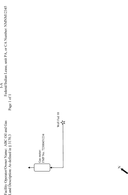
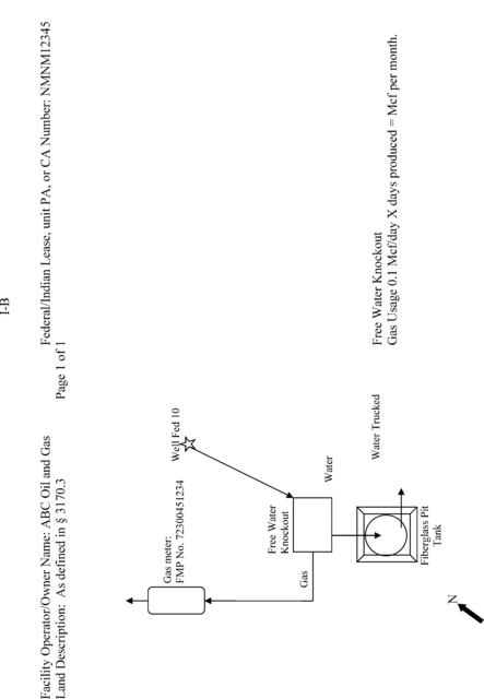
| Diagrams | Description |
|---|---|
| I-A | Gas well without separation equipment. |
| I-B | Gas well with separation equipment. |
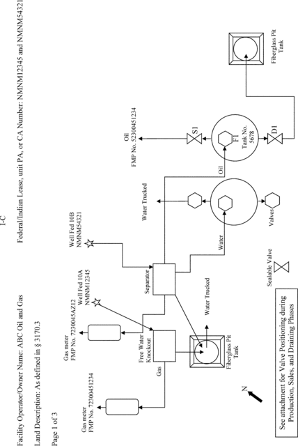
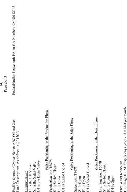
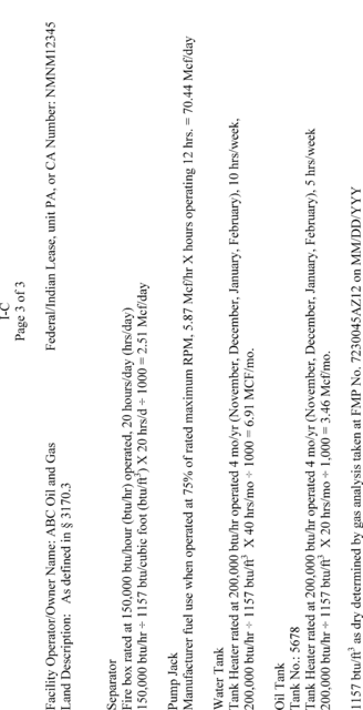
| I-C | Single operator with co-located facilities single oil tank, gas, and water storage. |
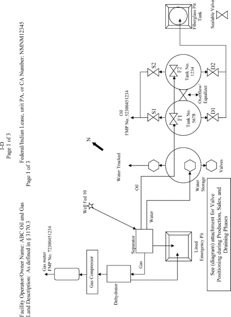
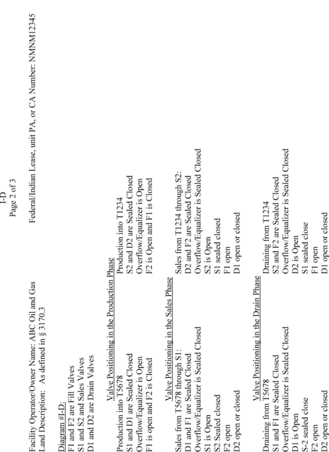
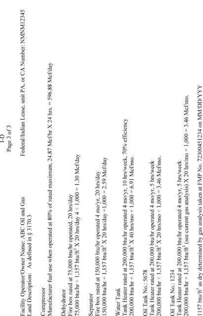
| I-D | Oil sales with multiple oil tanks, gas, and water storage. |
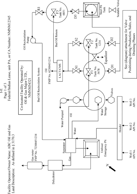
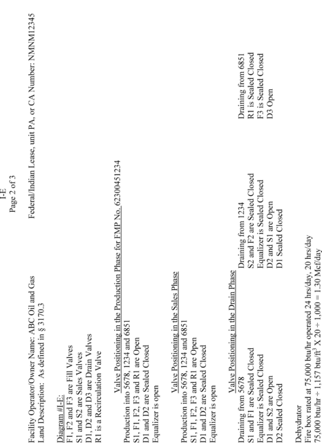
| I-E | Co-located facilities with multiple operators, oil sales by liquid meter (Lease Automatic Custody Transfer or Coriolis Measurement System), gas, and water storage. |
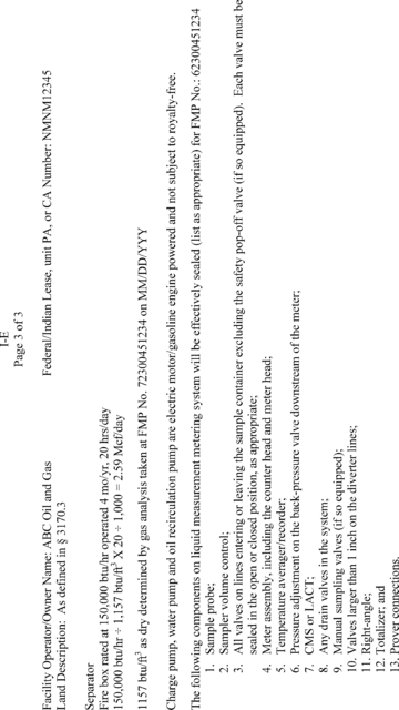
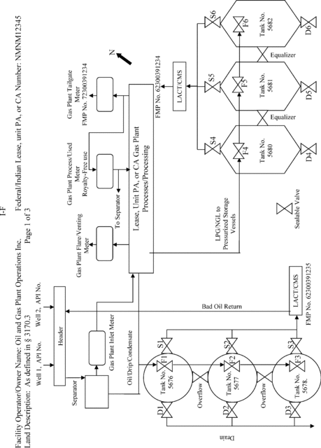
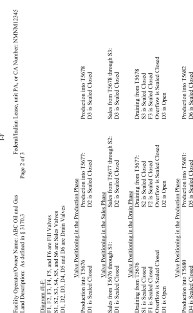
| I-F | On-lease gas plant, with oil sales by liquid meter, Liquefied Petroleum Gas (LPG)/Natural Gas Liquids (NGL) sales by liquid meter, inlet gas, tailgate gas, flared or vented and plant process gas used. |
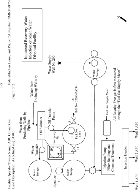
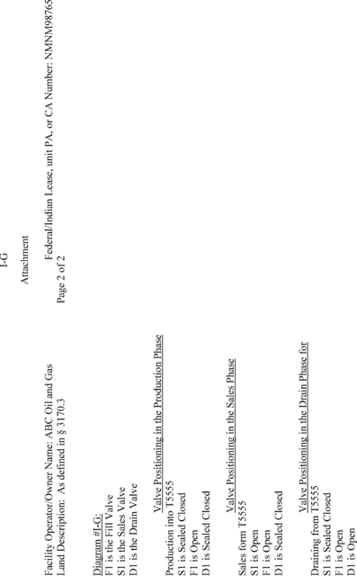
| I-G | Enhanced recovery water injection or other water disposal facility. |
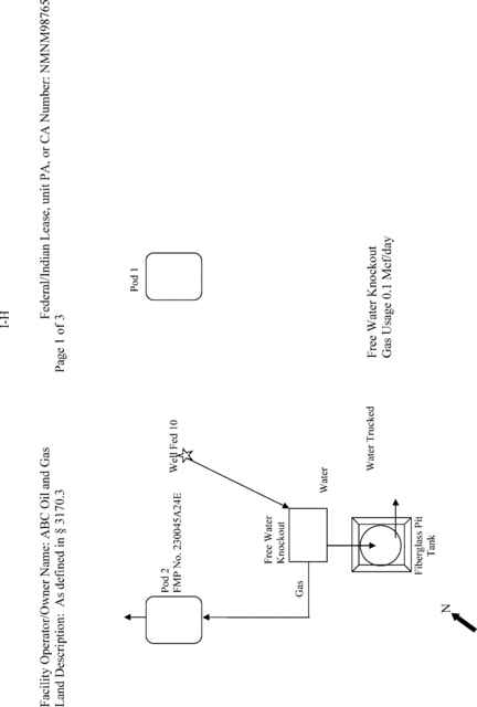
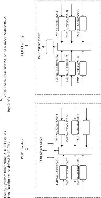
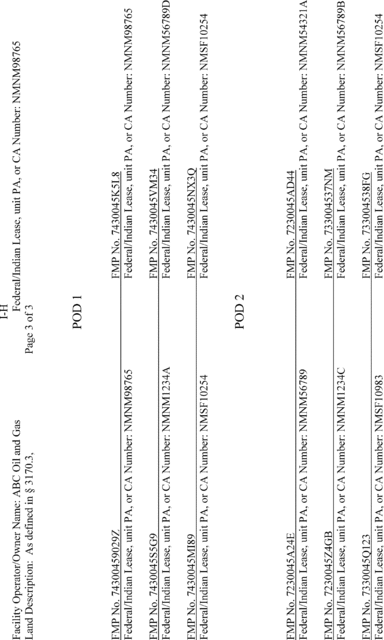
| I-H | Pod Facility. |
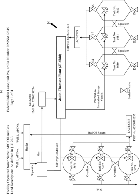
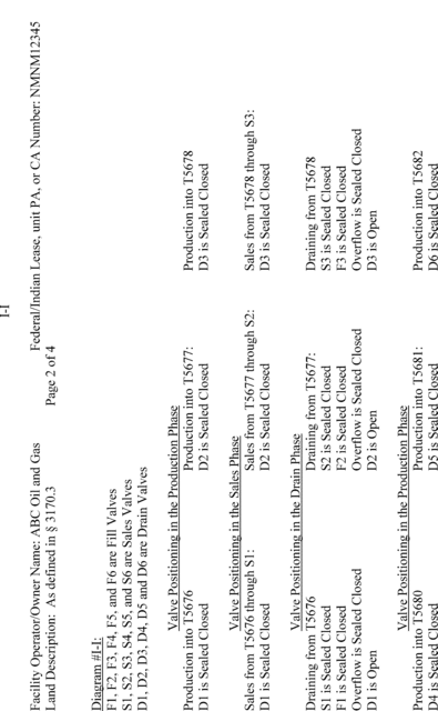
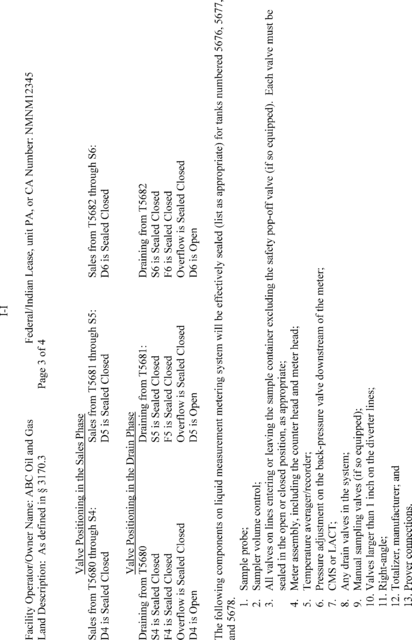
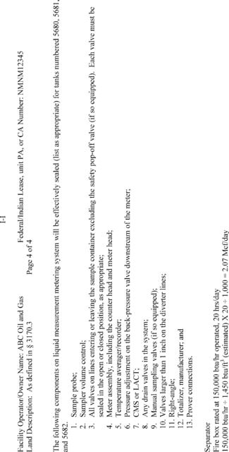
| I-I | On-lease with gas measurement after the Joule-Thomson Plant (JT-Skid), oil sales by liquid meter, Liquefied Petroleum Gas (LPG)/Natural Gas Liquids (NGL) sales by liquid meter. |
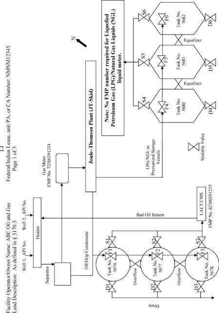
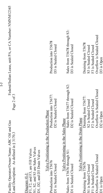
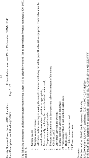
| I-J | On-lease with gas measurement before the Joule-Thomson Plant (JT-Skid) and oil sales by liquid meter. |
Note: No FMP number required for Liquefied Petroleum Gas (LPG)/Natural Gas Liquids (NGL) liquid meter.
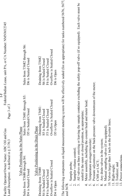
Appendix A is provided not as a requirement but solely as an example to aid operators, purchasers and transporters in determining what valves are considered “appropriate valves” subject to the seal requirements of this rule, and to aid in the preparation of facility diagrams. It is impossible to include every type of equipment that could be used or situation that could occur in production activities. In making the determination of what is an “appropriate valve,” the entire facility must be considered as a whole, including the facility size, the equipment type, and the on-going activities at the facility.
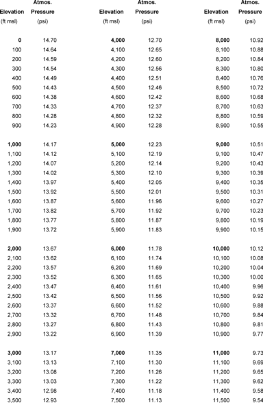
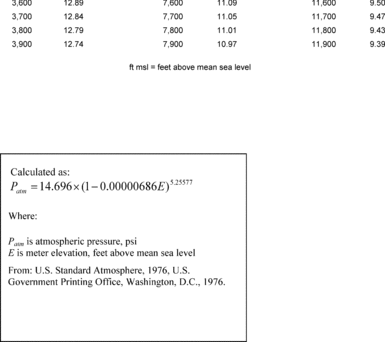
Appendix A to Subpart 3175 of Part 3170 - Table of Atmospheric Pressures
43:2.1.1.3.50.5.76.55.2 : Appendix A
Appendix A to Subpart 3175 of Part 3170 - Table of Atmospheric Pressures