Title 40
SECTION 86.884-9
86.884-9 Smoke measurement system.
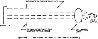
§ 86.884-9 Smoke measurement system.(a) Schematic drawing. The Figure I84-1 is a schematic drawing of the optical system of the light extinction meter.
(b) Equipment. The following equipment shall be used in the system.
(1) Adapter - the smokemeter optical unit may be mounted on a fixed or movable frame. The normal unrestricted shape of the exhaust plume shall not be modified by the adaptor, the meter, or any ventilatory system used to remove the exhaust from the test site.
(2) Smokemeter (light extinction meter) - continuous recording, full-flow light obscuration meter.
(i) It is positioned so that a built-in light beam traverses the exhaust smoke plume at right angles to the axis of the exhaust stream.
(ii) The smokemeter light source shall be an incandescent lamp with a color temperature range of 2800K to 3250K, or a light source with a spectral peak between 550 to 570 nanometers.
(iii) The light output is collimated to a beam with a maximum diameter of 1.125 inches and an included angle of divergence within a 6° included angle.
(iv) The light detector shall be a photocell or photodiode. If the light source is an incandescent lamp, the detector shall have a spectral response similar to the photopic curve of the human eye (a maximum response in the range of 550 to 570 nanometers, to less than 4 percent of that maximum response below 430 nanometers and above 680 nanometers).
(v) A collimating tube with apertures equal to the beam diameter is attached to the detector to restrict the viewing angle of the detector to within a 16° included angle.
(vi) An amplified signal corresponding to the amount of light blocked is recorded continuously on a remote recorder.
(vii) An air curtain across the light source and detector window assemblies may be used to minimize deposition of smoke particles on those surfaces provided that it does not measurably affect the opacity of the plume.
(viii) The smokemeter consists of two units; an optical unit and a remote control unit.
(ix) Light extinction meters employing substantially identical measurement principles and producing substantially equivalent results, but which employ other electronic and optical techniques, may be used only after having been approved in advance by the Administrator.
(3) Recorder - a continuous recorder, with variable chart speed over a minimal range of 0.5 to 8.0 inches per minute (or equivalent) and an automatic marker indicating 1-second intervals continuously records the exhaust gas opacity, engine rpm and throttle position.
(i) The recorder is equipped to indicate only when the throttle is in the fully open or fully closed position.
(ii) The recorder scale for opacity is linear and calibrated to read from 0 to 100 percent opacity full scale.
(iii) The opacity trace has a resolution within one percent opacity.
(iv) The recorder scale for engine rpm is linear and has a resolution of 30 rpm.
(v) The throttle position trace clearly indicates when the throttle is in the fully open and fully closed positions.
(vi) Any means other than a strip-chart recorder may be used provided it produces a permanent visual data record of quality equal to or better than that described above (e.g., tabulated data, traces, or plots).
(4) The recorder used with the smokemeter shall be capable of full-scale deflection in 0.5 second or less. The smokemeter-recorder combination may be damped so that signals with a frequency higher than 10 cycles per second are attenuated. A separate lowpass electronic filter with the following performance characteristics may be installed between the smokemeter and the recorder to achieve the high-frequency attenuation:
(i) Three decibel point - 10 cycles per second.
(ii) Insertion loss - zero ±0.5 decibel.
(iii) Selectivity - 12 decibels per octave above 10 cycles per second.
(iv) Attenuation - 27 decibels down at 40 cycles per second minimum.
(5) In lieu of the use of chart recorders, automatic data collection equipment may be used to record all required data. Automatic data processing equipment may then be used to perform the data analysis specified in § 86.884-13. The automatic data collection equipment must be capable of sampling at least two records per second.
(c) Assembling equipment. (1) The optical unit of the smokemeter shall be mounted radially to the exhaust pipe so that the measurement will be made at right angles to the axis of the exhaust plume. For an end-of-line smokemeter the distance from the optical centerline to the exhaust pipe outlet shall be 1 ±0.25 inch. The full flow of the exhaust stream shall be centered between the source and the detector apertures (or windows and lenses) and on the axis of the light beam.
(2) Power shall be supplied to the control unit of the smokemeter in time to allow at least 15 minutes for stabilization prior to testing.
[48 FR 52203, Nov. 16, 1983, as amended at 49 FR 48141, Dec. 10, 1984; 62 FR 47122, Sept. 5, 1997]