Title 40
SECTION 63.565
63.565 Test methods and procedures.
§ 63.565 Test methods and procedures.(a) Performance testing. The owner or operator of an affected source in § 63.562 shall comply with the performance testing requirements in § 63.7 of subpart A of this part in accordance with the provisions for applicability of subpart A to this subpart in Table 1 of § 63.560 and the performance testing requirements in this section.
(b) Pressure/vacuum settings of marine tank vessel's vapor collection equipment. For the purpose of determining compliance with § 63.563(a)(3), the following procedures shall be used:
(1) Calibrate and install a pressure measurement device (liquid manometer, magnehelic gauge, or equivalent instrument) capable of measuring up to the maximum relief set pressure of the pressure-vacuum vents;
(2) Connect the pressure measurement device to a pressure tap in the terminal's vapor collection system, located as close as possible to the connection with the marine tank vessel; and
(3) During the performance test required in § 63.563(b)(1), record the pressure every 5 minutes while a marine tank vessel is being loaded and record the highest instantaneous pressure and vacuum that occurs during each loading cycle.
(c) Vapor-tightness test procedures for the marine tank vessel. When testing a vessel for vapor tightness to comply with the marine vessel vapor-tightness requirements of § 63.563(a)(4)(i), the owner or operator of a source shall use the methods in either paragraph (c)(1) or (2) in this section.
(1) Pressure test for the marine tank vessel. (i) Each product tank shall be pressurized with dry air or inert gas to no more than the pressure of the lowest pressure relief valve setting.
(ii) Once the pressure is obtained, the dry air or inert gas source shall be shut off.
(iii) At the end of one-half hour, the pressure in the product tank and piping shall be measured. The change in pressure shall be calculated using the following formula:
P = Pi−Pf Where: P = change in pressure, inches of water. Pi = pressure in tank when air/gas source is shut off, inches of water. Pf = pressure in tank at the end of one-half hour after air/gas source is shut off, inches of water.(iv) The change in pressure, P, shall be compared to the pressure drop calculated using the following formula:
PM = 0.861 Pia L/V Where: PM = maximum allowable pressure change, inches of water. Pia = pressure in tank when air/gas source is shut off, psia. L = maximum permitted loading rate of vessel, barrels per hour. V = total volume of product tank, barrels.(v) If P≤PM, the vessel is vapor tight.
(vi) If P<PM, the vessel is not vapor tight and the source of the leak must be identified and repaired prior to retesting.
(2) Leak test for the marine tank vessel. Each owner or operator of a source complying with §§ 63.563(a)(4)(ii) or (iii) shall use Method 21 as the vapor-tightness leak test for marine tank vessels. The test shall be conducted during the final 20 percent of loading of each product tank of the marine vessel, and it shall be applied to any potential sources of vapor leaks on the vessel.
(d) Combustion (except flare) and recovery control device performance test procedures. (1) All testing equipment shall be prepared and installed as specified in the appropriate test methods.
(2) All testing shall be performed during the last 20 percent of loading of a tank or compartment.
(3) All emission testing intervals shall consist of each 5 minute period during the performance test. For each interval, the following shall be performed:
(i) Readings. The reading from each measurement instrument shall be recorded.
(ii) Sampling Sites. Method 1 or 1A of appendix A of part 60 of this chapter, as appropriate, shall be used for selection of sampling sites. Sampling sites shall be located at the inlet and outlet of the combustion device or recovery device except for owners or operators complying with the 1,000 ppmv VOC emissions limit for gasoline vapors under § 63.563(b)(6) or (7), where the sampling site shall be located at the outlet of the recovery device.
(iii) Volume exhausted. The volume exhausted shall be determined using Method 2, 2A, 2C, or 2D of appendix A of part 60 of this chapter, as appropriate.
(4) Combustion devices, except flares. The average VOC concentration in the vent upstream and downstream of the control device shall be determined using Method 25 of appendix A of part 60 of this chapter for combustion devices, except flares. The average VOC concentration shall correspond to the volume measurement by taking into account the sampling system response time.
(5) Recovery devices. The average VOC concentration in the vent upstream and downstream of the control device shall be determined using Method 25A or 25B of appendix A-7 to part 60 of this chapter for recovery devices. The average VOC concentration shall correspond to the volume measurement by taking into account the sampling system response time.
(6) The VOC mass at the inlet and outlet of the combustion or recovery device during each testing interval shall be calculated as follows:
Mj = FKVs CVOC Where: Mj = mass of VOC at the inlet and outlet of the combustion or recovery device during testing interval j, kilograms (kg). F = 10−6 = conversion factor, (cubic meters VOC/cubic meters air)(1/ppmv) (m 3 VOC/m 3 air)(1/ppmv). K = density, kilograms per cubic meter (kg/m 3 VOC), standard conditions, 20 °C and 760 mm Hg. Vs = volume of air-vapor mixture at the inlet and outlet of the combustion or recovery device, cubic meters (m 3) at standard conditions, 20 °C and 760 mm Hg. CVOC = VOC concentration (as measured) at the inlet and outlet of the combustion or recovery device, ppmv, dry basis. s = standard conditions, 20 °C and 760 mm Hg.(7) The VOC mass emission rates at the inlet and outlet of the recovery or combustion device shall be calculated as follows:
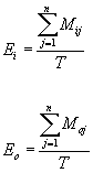 Where:
Ei, Eo = mass flow rate of VOC at the inlet (i) and outlet (o) of
the recovery or combustion device, kilogram per hour (kg/hr). Mij,
Moj = mass of VOC at the inlet (i) or outlet (o) during testing
interval j, kg. T = Total time of all testing intervals, hour. n =
number of testing intervals.
Where:
Ei, Eo = mass flow rate of VOC at the inlet (i) and outlet (o) of
the recovery or combustion device, kilogram per hour (kg/hr). Mij,
Moj = mass of VOC at the inlet (i) or outlet (o) during testing
interval j, kg. T = Total time of all testing intervals, hour. n =
number of testing intervals.
(8) Where Method 25, 25A, or 25B is used to measure the percent reduction in VOC, the percent reduction across the combustion or recovery device shall be calculated as follows:
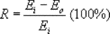 Where: R
= control efficiency of control device, percent. Ei = mass flow
rate of VOC at the inlet to the combustion or recovery device as
calculated under paragraph (c)(7) of this section, kg/hr. Eo = mass
flow rate of VOC at the outlet of the combustion or recovery
device, as calculated under paragraph (c)(7) of this section,
kg/hr.
Where: R
= control efficiency of control device, percent. Ei = mass flow
rate of VOC at the inlet to the combustion or recovery device as
calculated under paragraph (c)(7) of this section, kg/hr. Eo = mass
flow rate of VOC at the outlet of the combustion or recovery
device, as calculated under paragraph (c)(7) of this section,
kg/hr.
(9) Repeat the procedures in paragraph (d)(1) through (d)(8) of this section 3 times. The arithmetic average percent efficiency of the three runs shall determine the overall efficiency of the control device.
(10) Use of methods other than Method 25, 25A, or 25B shall be validated pursuant to Method 301 of appendix A to part 63 of this chapter.
(e) Performance test for flares. When a flare is used to comply with § 63.562(b)(2), (3), and (4), (c)(3) and (4), and (d)(2), the source must demonstrate that the flare meets the requirements of § 63.11 of subpart A of this part. In addition, a performance test according to Method 22 of appendix A of part 63 shall be performed to determine visible emissions. The observation period shall be at least 2 hours and shall be conducted according to Method 22. Performance testing shall be conducted during three complete loading cycles with a separate test run for each loading cycle. The observation period for detecting visible emissions shall encompass each loading cycle. Integrated sampling to measure process vent stream flow rate shall be performed continuously during each loading cycle. The owner or operator shall record all visible emission readings, heat content determinations, flow rate measurements, maximum permitted velocity calculations, and exit velocity determinations made during the performance test.
(f) Baseline temperature. The procedures in this paragraph shall be used to determine the baseline temperature required in § 63.563(b)(4), (6), and (7) for combustion devices, carbon adsorber beds, and condenser/refrigeration units, respectively, and to monitor the temperature as required in § 63.564(e), (g), and (h). The owner or operator shall comply with either paragraph (f)(1) or (2) of this section.
(1) Baseline temperature from performance testing. The owner or operator shall establish the baseline temperature as the temperature at the outlet point of the unit averaged over three test runs from paragraph (d) of this section. Temperature shall be measured every 15 minutes.
(2) Baseline temperature from manufacturer. The owner or operator shall establish the baseline temperature as the manufacturer recommended minimum operating temperature for combustion devices, maximum operating temperature for condenser units, and maximum operating temperature for carbon beds of carbon adsorbers.
(g) Baseline outlet VOC concentration. The procedures in this paragraph shall be used to determine the outlet VOC concentration required in § 63.563(b)(4), (6), (7), and (8) for combustion devices except flare, carbon adsorbers, condenser/refrigeration units, and absorbers, respectively, and to monitor the VOC concentration as required in § 63.564(e), (g), (h), and (i). The owner or operator shall use the procedures outlined in Method 25A or 25B. For the baseline VOC concentration, the arithmetic average of the outlet VOC concentration from three test runs from paragraph (d) of this section shall be calculated for the control device. The VOC concentration shall be measured at least every 15 minutes. Compliance testing of VOC CEMS shall be performed using PS 8.
(h) Baseline regeneration time for carbon bed regeneration. The procedures in this paragraph shall be used to demonstrate the baseline regeneration time for the vacuum stage of carbon bed regeneration required in § 63.563(b)(6) for a carbon adsorber and to monitor the regeneration time for the vacuum regeneration as required in § 63.564(g). The owner or operator shall comply with paragraph (h)(1) or (2).
(1) Baseline regeneration time from performance testing. The owner or operator shall establish the baseline regeneration time as the length of time for the vacuum stage of carbon bed regeneration averaged over three test runs from paragraph (d) of this section.
(2) Baseline regeneration time from manufacturer recommendation. The owner or operator shall establish the baseline regeneration time as the manufacturer recommended minimum regeneration time for the vacuum stage of carbon bed regeneration.
(i) Baseline vacuum pressure for carbon bed regeneration. The procedures in this paragraph shall be used to demonstrate the baseline vacuum pressure for the vacuum stage of carbon bed regeneration required in § 63.563(b)(6) for a carbon adsorber and to monitor the vacuum pressure as required in § 63.564(g). The owner or operator shall establish the baseline vacuum pressure as the manufacturer recommended minimum vacuum for carbon bed regeneration.
(j) Baseline total stream flow. The procedures in this paragraph shall be used to demonstrate the baseline total stream flow for steam regeneration required in § 63.563(b)(6) for a carbon adsorber and to monitor the total stream flow as required in § 63.564(g). The owner or operator shall establish the baseline stream flow as the manufacturer recommended minimum total stream flow for carbon bed regeneration.
(k) Baseline L/V ratio. The procedures in this paragraph shall be used to determine the baseline L/V ratio required in § 63.563(b)(8) for an absorber and to monitor the L/V ratio as required in § 63.564(i). The owner or operator shall comply with either paragraph (k)(1) or (2) of this section.
(1) Baseline L/V ratio from performance test. The owner or operator shall establish the baseline L/V ratio as the calculated value of the inlet liquid flow divided by the inlet gas flow to the absorber averaged over three test runs using the procedures in paragraph (d) of this section.
(2) Baseline L/V ratio from manufacturer. The owner or operator shall establish the baseline L/V ratio as the manufacturer recommended minimum L/V ratio for absorber operation.
(l) Emission estimation procedures. For sources with emissions less than 10 or 25 tons and sources with emissions of 10 or 25 tons, the owner or operator shall calculate an annual estimate of HAP emissions, excluding commodities exempted by § 63.560(d), from marine tank vessel loading operations. Emission estimates and emission factors shall be based on test data, or if test data is not available, shall be based on measurement or estimating techniques generally accepted in industry practice for operating conditions at the source.
(m) Alternate test procedures. (1) Alternate test procedures to those described in this section may be used upon application to, and approval by, the Administrator.
(2) If the owner or operator intends to demonstrate compliance by using an alternative to any test method specified, the owner or operator shall refrain from conducting the performance test until the Administrator approves the use of the alternative method when the Administrator approves the site-specific test plan (if review of the site-specific test plan is requested) or until after the alternative method is approved (see § 63.7(f) of subpart A of this part). If the Administrator does not approve the site-specific test plan (if review is requested) or the use of the alternative method within 30 days before the test is scheduled to begin, the performance test dates specified in § 63.563(b)(1) shall be extended such that the owner or operator shall conduct the performance test within 60 calendar days after the Administrator approves the site-specific test plan or after use of the alternative method is approved. Notwithstanding the requirements in the preceding two sentences, the owner or operator may proceed to conduct the performance test as required in this section (without the Administrator's prior approval of the site-specific test plan) if he/she subsequently chooses to use the specified testing and monitoring methods instead of an alternative.
[60 FR 48399, Sept. 19, 1995, as amended at 79 FR 11283, Feb. 27, 2014]