Title 40
SECTION 1037.550
1037.550 Powertrain testing.
§ 1037.550 Powertrain testing.(a) This section describes how to determine engine fuel maps using a measurement procedure that involves testing an engine coupled with a powertrain to simulate vehicle operation. Engine fuel maps are part of demonstrating compliance with Phase 2 vehicle standards under this part 1037; this fuel-mapping information may come from different types of testing as described in 40 CFR 1036.510.
(b) Perform powertrain testing to establish measured fuel-consumption rates over applicable duty cycles for several different vehicle configurations. The following general provisions apply:
(1) Measure NOX emissions for each sampling period in grams. You may perform these measurements using a NOX emission-measurement system that meets the requirements of 40 CFR part 1065, subpart J. Include these measured NOX values any time you report to us your greenhouse gas emissions or fuel consumption values from testing under this section. If a system malfunction prevents you from measuring NOX emissions during a test under this section but the test otherwise gives valid results, you may consider this a valid test and omit the NOX emission measurements; however, we may require you to repeat the test if we determine that you inappropriately voided the test with respect to NOX emission measurement.
(2) This section uses engine parameters and variables that are consistent with 40 CFR part 1065.
(3) While this section includes the detailed equations, you need to develop your own driver model and vehicle model; we recommend that you use the MATLAB/Simulink code provided at www.epa.gov/otaq/climate/gem.htm.
(c) Select an engine and powertrain for testing as described in § 1037.231.
(d) Set up the engine according to 40 CFR 1065.110. The default test configuration involves connecting the powertrain's transmission output shaft directly to the dynamometer. You may instead set up the dynamometer to connect at the wheel hubs if your powertrain configuration requires it, such as for hybrid powertrains, or if you want to represent the axle performance with powertrain test results. If you connect at the wheel hubs, input your test results into GEM to reflect this.
(e) Cool the powertrain during testing so temperatures for intake-air, oil, coolant, block, head, transmission, battery, and power electronics are within their expected ranges for normal operation. You may use auxiliary coolers and fans.
(f) Set the dynamometer to operate in speed-control mode. Record data as described in 40 CFR 1065.202. Command and control dynamometer speed at a minimum of 5 Hz. If you choose to command the dynamometer at a slower rate than the calculated dynamometer speed setpoint, use good engineering judgment to subsample the calculated setpoints for use in commanding the dynamomemter speed setpoint. Design a vehicle model to use the measured torque and calculate the dynamometer speed setpoint at a rate of at least 100 Hz, as follows:
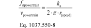
(1) Calculate the dynamometer's angular speed target, ƒnref,dyno, based on the simulated linear speed of the tires:
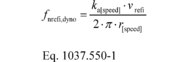 Where:
ka[speed] = drive axle ratio as determined in paragraph (h)
of this section. vrefi = simulated vehicle reference speed.
Use the unrounded result for calculating ƒnrefi,dyno.
r[speed] = tire radius as determined in paragraph (h) of
this section.
Where:
ka[speed] = drive axle ratio as determined in paragraph (h)
of this section. vrefi = simulated vehicle reference speed.
Use the unrounded result for calculating ƒnrefi,dyno.
r[speed] = tire radius as determined in paragraph (h) of
this section. 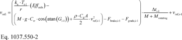 Where: i =
a time-based counter corresponding to each measurement during the
sampling period. Let vref1 = 0; start calculations at
i = 2. A 10-minute sampling period will generally involve
60,000 measurements. T = instantaneous measured torque.
Eƒƒaxle = axle efficiency. Use Eƒƒaxle = 0.955 for
T > 0, and use Eƒƒaxle = 1/0.955 for T <
0. To calculate ƒnrefi,dyno for a dynamometer connected at
the wheel hubs, as described in paragraph (f)(2) of this section,
use Eƒƒaxle = 1.0. M = vehicle mass for a vehicle
class as determined in paragraph (h) of this section. g =
gravitational constant = 9.81 m/s 2. Crr = coefficient of
rolling resistance for a vehicle class as determined in paragraph
(h) of this section. Gi-1 = the percent grade interpolated
at distance, Di-1, from the duty cycle in Appendix IV
corresponding to measurement (i−1).
Where: i =
a time-based counter corresponding to each measurement during the
sampling period. Let vref1 = 0; start calculations at
i = 2. A 10-minute sampling period will generally involve
60,000 measurements. T = instantaneous measured torque.
Eƒƒaxle = axle efficiency. Use Eƒƒaxle = 0.955 for
T > 0, and use Eƒƒaxle = 1/0.955 for T <
0. To calculate ƒnrefi,dyno for a dynamometer connected at
the wheel hubs, as described in paragraph (f)(2) of this section,
use Eƒƒaxle = 1.0. M = vehicle mass for a vehicle
class as determined in paragraph (h) of this section. g =
gravitational constant = 9.81 m/s 2. Crr = coefficient of
rolling resistance for a vehicle class as determined in paragraph
(h) of this section. Gi-1 = the percent grade interpolated
at distance, Di-1, from the duty cycle in Appendix IV
corresponding to measurement (i−1). 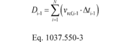 r = air density at
reference conditions. Use ρ = 1.20 kg/m 3. CdA
= drag area for a vehicle class as determined in paragraph (h) of
this section. Fbrake = instantaneous braking force applied
by the driver model.
r = air density at
reference conditions. Use ρ = 1.20 kg/m 3. CdA
= drag area for a vehicle class as determined in paragraph (h) of
this section. Fbrake = instantaneous braking force applied
by the driver model. 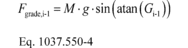 Δt = the
time interval between measurements. For example, at 100 Hz,
Δt = 0.0100 seconds. Mrotating = inertial mass of
rotating components. Let Mrotating = 340 kg for vocational
Light HDV or vocational Medium HDV. See paragraph (h) of this
section for tractors and for vocational Heavy HDV. Example:
Δt = the
time interval between measurements. For example, at 100 Hz,
Δt = 0.0100 seconds. Mrotating = inertial mass of
rotating components. Let Mrotating = 340 kg for vocational
Light HDV or vocational Medium HDV. See paragraph (h) of this
section for tractors and for vocational Heavy HDV. Example:
This example is for a vocational Light HDV or vocational Medium HDV with 6 speed automatic transmission at B speed (Test 4 in Table 2 of 40 CFR 1036.540).
kaB = 4.0 rB = 0.399 m T1000-1 = 500.0 N·m Crr = 6.9 kg/tonne = 6.9·10−3 kg/kg M = 11408 kg CdA = 5.4 m 2 G1000-1 = 1.0% = 0.018 Fbrake1000-1 = 0 N vref1000-1 = 20.0 m/s
Fgrade1001-1 = 11408·9.81·sin(atan(0.018)) = 2014.1N
Δt = 0.0100 s Mrotating = 340 kg
Fbrake1000-1 = 0 N vref1000-1 = 20.0 m/s
Fgrade1001-1 = 11408·9.81·sin(atan(0.018)) = 2014.1N
Δt = 0.0100 s Mrotating = 340 kg 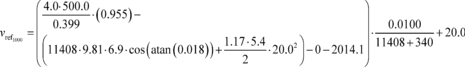 vref1000 =
20.00129 m/s
vref1000 =
20.00129 m/s 
(2) For testing with the dynamometer connected at the wheel hubs, calculate fnref,dyno using the following equation:

(g) Design a driver model to simulate a human driver modulating the throttle and brake pedals to follow the test cycle as closely as possible. The driver model must meet the speed requirements for operation over the highway cruise cycles as described in § 1037.510 and for operation over the transient cycle as described in 40 CFR 1066.425(b). The exceptions in 40 CFR 1066.425(b)(4) apply to the transient cycle and the highway cruise cycles. Design the driver model to meet the following specifications:
(1) Send a brake signal when throttle position is zero and vehicle speed is greater than the reference vehicle speed from the test cycle. Include a delay before changing the brake signal to prevent dithering, consistent with good engineering judgment.
(2) Allow braking only if throttle position is zero.
(3) Compensate for the distance driven over the duty cycle over the course of the test. Use the following equation to perform the compensation in real time to determine your time in the cycle:
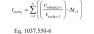 Where:
vvehicle = measured vehicle speed. vcycle = reference
speed from the test cycle. If vcycle,i-1 < 1.0 m/s, set
vcycle,i-1 = vvehicle,i-1.
Where:
vvehicle = measured vehicle speed. vcycle = reference
speed from the test cycle. If vcycle,i-1 < 1.0 m/s, set
vcycle,i-1 = vvehicle,i-1.
(h) Configure the vehicle model in the test cell to test the powertrain using at least three equally spaced axle ratios or tire sizes and three different road loads (nine configurations), or at least four equally spaced axle ratios or tire sizes and two different road loads (eight configurations) to cover the range of intended vehicle applications. Select axle ratios to represent the full range of expected vehicle installations. Determine the vehicle model inputs for vehicle mass, CdA, and Crr for a set of vehicle configurations as described in 40 CFR 1036.540(c)(3). You may instead test to simulate eight or nine vehicle configurations from different vehicle categories if you limit your powertrains to a certain range of vehicles. For example, if your powertrain will be installed only in vocational Medium HDV and vocational Heavy HDV, you may perform testing to represent eight or nine vehicle configurations using vehicle masses for Medium HDV and Heavy HDV, the predefined CdA for those vehicles, and the lowest and highest Crr of the tires that will be installed on those vehicles. Also, instead of selecting specific axle ratios and tire size as described in this paragraph (h), you may select equally spaced axle ratios and tire sizes that cover the range of minimum and maximum engine speed over vehicle speed when the transmission is in top gear for the vehicles the powertrain will be installed in.
(i) Operate the powertrain over each of the duty cycles specified in § 1037.510(a)(2), and for each applicable test configuration identified in 40 CFR 1036.540(c). For each duty cycle, precondition the powertrain using the Test 1 vehicle configuration and test the different configurations in numerical order starting with Test 1. If an infrequent regeneration event occurs during testing, void the test, but continue operating the vehicle to allow the regeneration event to finish, then precondition the engine to the same condition as would apply for normal testing and restart testing at the start of the same duty cycle for that test configuration. For PHEV powertrains, precondition the battery and then complete all back to back tests for each test configuration according to 40 CFR 1066.501 before moving to the next test configuration. You may send signals to the engine controller during the test, such as cycle road grade and vehicle speed, if that allows powertrain operation during the test to better represent real-world operation.
(j) Collect and measure emissions as described in 40 CFR part 1065. For hybrid powertrains with no plug-in capability, correct for the net energy change of the energy storage device as described in 40 CFR 1066.501. For PHEV powertrains, follow 40 CFR 1066.501 to determine End-of-Test for charge-depleting operation. You must get our approval in advance for your utility factor curve; we will approve it if you can show that you created it from sufficient in-use data of vehicles in the same application as the vehicles in which the PHEV powertrain will be installed.
(k) For each test point, validate the measured output speed with the corresponding reference values. If the range of reference speed is less than 10 percent of the mean reference speed, you need to meet only the standard error of estimate in Table 1 of this section. You may delete points when the vehicle is stopped. Apply cycle-validation criteria for each separate transient or highway cruise cycle based on the following parameters:
Table 1 of § 1037.550 - Statistical Criteria for Validating Duty Cycles
| Parameter 1 | Speed control |
|---|---|
| Slope, a1 | 0.990 ≤ a1 ≤ 1.010. |
| Absolute value of intercept, |a0| | ≤2.0% of maximum test speed. |
| Standard error of estimate, SEE | ≤2.0% of maximum test speed. |
| Coefficient of determination, r 2 | ≥0.990. |
1 Determine values for specified parameters as described in 40 CFR 1065.514(e) by comparing measured and reference values for fnref,dyno.
(l) [Reserved]
(m) Calculate mass of fuel consumed for all duty cycles except idle as described in 40 CFR 1036.540(d)(4).
(n) Determine the mass of fuel consumed at idle for the applicable duty cycles as follows:
(1) Measure fuel consumption with a fuel flow meter and report the mean fuel mass flow rate for each duty cycle as applicable, m fuelidle.
(2) For measurements that do not involve measured fuel mass flow rate, calculate the fuel mass flow rate for each duty cycle, m fuelidle, for each set of vehicle settings, as follows:
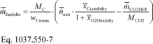 Where:
MC = molar mass of carbon. wCmeas = carbon mass
fraction of fuel (or mixture of test fuels) as determined by in CFR
1065.655(d), except that you may not use the default properties in
Table 1 of 40 CFR 1065.655 to determine α, β, and
wC for liquid fuels. n exh = the mean raw exhaust
molar flow rate from which you measured emissions according to 40
CFR 1065.655. x Ccombdry = the mean concentration of carbon
from fuel and any injected fluids in the exhaust per mole of dry
exhaust. x H2Oexhdry = the mean concentration of H2O in
exhaust per mole of dry exhaust. m H2O2DEF= the mean CO2
mass emission rate resulting from diesel exhaust fluid
decomposition over the duty cycle as determined in 40 CFR
1036.535(b)(10). If your engine does not use diesel exhaust fluid,
or if you choose not to perform this correction, set m
CO2DEF equal to 0. MCO2 = molar mass of carbon dioxide.
Example: MC = 12.0107 g/mol wCmeas = 0.867 n
exh = 25.534 mol/s x Ccombdry = 2.805·10−3 mol/mol x
H2Oexhdry = 3.53·10−2 mol/mol m CO2DEF = 0.0726 g/s
MCO2 = 44.0095
Where:
MC = molar mass of carbon. wCmeas = carbon mass
fraction of fuel (or mixture of test fuels) as determined by in CFR
1065.655(d), except that you may not use the default properties in
Table 1 of 40 CFR 1065.655 to determine α, β, and
wC for liquid fuels. n exh = the mean raw exhaust
molar flow rate from which you measured emissions according to 40
CFR 1065.655. x Ccombdry = the mean concentration of carbon
from fuel and any injected fluids in the exhaust per mole of dry
exhaust. x H2Oexhdry = the mean concentration of H2O in
exhaust per mole of dry exhaust. m H2O2DEF= the mean CO2
mass emission rate resulting from diesel exhaust fluid
decomposition over the duty cycle as determined in 40 CFR
1036.535(b)(10). If your engine does not use diesel exhaust fluid,
or if you choose not to perform this correction, set m
CO2DEF equal to 0. MCO2 = molar mass of carbon dioxide.
Example: MC = 12.0107 g/mol wCmeas = 0.867 n
exh = 25.534 mol/s x Ccombdry = 2.805·10−3 mol/mol x
H2Oexhdry = 3.53·10−2 mol/mol m CO2DEF = 0.0726 g/s
MCO2 = 44.0095 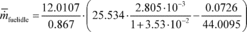 m fuelidle
= 0.405 g/s = 1458.6 g/hr
m fuelidle
= 0.405 g/s = 1458.6 g/hr
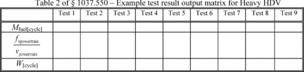
(o) Use the results of powertrain testing to determine GEM inputs for the different simulated vehicle configurations as follows:
(1) Select fuel-consumption rates, mfuel[cycle], in g/cycle. In addition, declare a fuel mass consumption rate for each applicable idle duty cycle, m fuelidle. These declared values may not be lower than any corresponding measured values determined in this section. You may select any value that is at or above the corresponding measured value. These declared fuel-consumption rates, which serve as emission standards, represent collectively as the certified powertrain fuel map.
(2) Powertrain output speed per unit of vehicle speed. If the test is done with the dynamometer connected at the wheel hubs set ka to the axle ratio of the rear axle that was used in the test. If the vehicle does not have a drive axle, such as hybrid vehicles with direct electric drive, let ka = 1.
(3) Positive work, W[cycle], over the duty cycle at the transmission output or wheel hubs from the powertrain test.
(4) The following table illustrates the GEM data inputs corresponding to the different vehicle configurations:
(p) Correct the measured or calculated fuel mass, mfuel, and idle fuel mass flow rate, m fuelidle if applicable, for each test result to a mass-specific net energy content of a reference fuel as described in § 1036.535(b)(11), replacing m fuel with mfuel where applicable in Eq. 1036.535-3.
(q) For each test run, record the engine speed and torque as defined in 40 CFR 1065.915(d)(5) with a minimum sampling frequency of 1 Hz. These engine speed and torque values represent a duty cycle that can be used for separate testing with an engine mounted on an engine dynamometer, such as for a selective enforcement audit as described in § 1037.301.
[81 FR 74048, Oct. 25, 2016; 82 FR 29762, June 30, 2017]