Appendix A to Part 75—Specifications and Test Procedures
1. Installation and Measurement Location 1.1 Gas Monitors(a) Following the procedures in section 8.1.1 of Performance Specification 2 in appendix B to part 60 of this chapter, install the pollutant concentration monitor or monitoring system at a location where the pollutant concentration and emission rate measurements are directly representative of the total emissions from the affected unit. Select a representative measurement point or path for the monitor probe(s) (or for the path from the transmitter to the receiver) such that the SO2, CO2, O2, or NOX concentration monitoring system or NOX-diluent CEMS (NOX pollutant concentration monitor and diluent gas monitor) will pass the relative accuracy test (see section 6 of this appendix).
(b) It is recommended that monitor measurements be made at locations where the exhaust gas temperature is above the dew-point temperature. If the cause of failure to meet the relative accuracy tests is determined to be the measurement location, relocate the monitor probe(s).
1.1.1 Point MonitorsLocate the measurement point (1) within the centroidal area of the stack or duct cross section, or (2) no less than 1.0 meter from the stack or duct wall.
1.1.2 Path MonitorsLocate the measurement path (1) totally within the inner area bounded by a line 1.0 meter from the stack or duct wall, or (2) such that at least 70.0 percent of the path is within the inner 50.0 percent of the stack or duct cross-sectional area, or (3) such that the path is centrally located within any part of the centroidal area.
1.2 Flow MonitorsInstall the flow monitor in a location that provides representative volumetric flow over all operating conditions. Such a location is one that provides an average velocity of the flue gas flow over the stack or duct cross section, provides a representative SO2 emission rate (in lb/hr), and is representative of the pollutant concentration monitor location. Where the moisture content of the flue gas affects volumetric flow measurements, use the procedures in both Reference Methods 1 and 4 of appendix A to part 60 of this chapter to establish a proper location for the flow monitor. The EPA recommends (but does not require) performing a flow profile study following the procedures in 40 CFR part 60, appendix A, method, 1, sections 11.5 or 11.4 for each of the three operating or load levels indicated in section 6.5.2.1 of this appendix to determine the acceptability of the potential flow monitor location and to determine the number and location of flow sampling points required to obtain a representative flow value. The procedure in 40 CFR part 60, appendix A, Test Method 1, section 11.5 may be used even if the flow measurement location is greater than or equal to 2 equivalent stack or duct diameters downstream or greater than or equal to 1/2 duct diameter upstream from a flow disturbance. If a flow profile study shows that cyclonic (or swirling) or stratified flow conditions exist at the potential flow monitor location that are likely to prevent the monitor from meeting the performance specifications of this part, then EPA recommends either (1) selecting another location where there is no cyclonic (or swirling) or stratified flow condition, or (2) eliminating the cyclonic (or swirling) or stratified flow condition by straightening the flow, e.g., by installing straightening vanes. EPA also recommends selecting flow monitor locations to minimize the effects of condensation, coating, erosion, or other conditions that could adversely affect flow monitor performance.
1.2.1 Acceptability of Monitor LocationThe installation of a flow monitor is acceptable if either (1) the location satisfies the minimum siting criteria of method 1 in appendix A to part 60 of this chapter (i.e., the location is greater than or equal to eight stack or duct diameters downstream and two diameters upstream from a flow disturbance; or, if necessary, two stack or duct diameters downstream and one-half stack or duct diameter upstream from a flow disturbance), or (2) the results of a flow profile study, if performed, are acceptable (i.e., there are no cyclonic (or swirling) or stratified flow conditions), and the flow monitor also satisfies the performance specifications of this part. If the flow monitor is installed in a location that does not satisfy these physical criteria, but nevertheless the monitor achieves the performance specifications of this part, then the location is acceptable, notwithstanding the requirements of this section.
1.2.2 Alternative Monitoring LocationWhenever the owner or operator successfully demonstrates that modifications to the exhaust duct or stack (such as installation of straightening vanes, modifications of ductwork, and the like) are necessary for the flow monitor to meet the performance specifications, the Administrator may approve an interim alternative flow monitoring methodology and an extension to the required certification date for the flow monitor.
Where no location exists that satisfies the physical siting criteria in section 1.2.1, where the results of flow profile studies performed at two or more alternative flow monitor locations are unacceptable, or where installation of a flow monitor in either the stack or the ducts is demonstrated to be technically infeasible, the owner or operator may petition the Administrator for an alternative method for monitoring flow.
2. Equipment Specifications 2.1 Instrument Span and RangeIn implementing sections 2.1.1 through 2.1.6 of this appendix, set the measurement range for each parameter (SO2, NOX, CO2, O2, or flow rate) high enough to prevent full-scale exceedances from occurring, yet low enough to ensure good measurement accuracy and to maintain a high signal-to-noise ratio. To meet these objectives, select the range such that the majority of the readings obtained during typical unit operation are kept, to the extent practicable, between 20.0 and 80.0 percent of the full-scale range of the instrument. These guidelines do not apply to: (1) SO2 readings obtained during the combustion of very low sulfur fuel (as defined in § 72.2 of this chapter); (2) SO2 or NOX readings recorded on the high measurement range, for units with SO2 or NOX emission controls and two span values, unless the emission controls are operated seasonally (for example, only during the ozone season); or (3) SO2 or NOX readings less than 20.0 percent of full-scale on the low measurement range for a dual span unit, provided that the maximum expected concentration (MEC), low-scale span value, and low-scale range settings have been determined according to sections 2.1.1.2, 2.1.1.4(a), (b), and (g) of this appendix (for SO2), or according to sections 2.1.2.2, 2.1.2.4(a) and (f) of this appendix (for NOX).
2.1.1 SO2 Pollutant Concentration MonitorsDetermine, as indicated in sections 2.1.1.1 through 2.1.1.5 of this appendix the span value(s) and range(s) for an SO2 pollutant concentration monitor so that all potential and expected concentrations can be accurately measured and recorded. Note that if a unit exclusively combusts fuels that are very low sulfur fuels (as defined in § 72.2 of this chapter), the SO2 monitor span requirements in § 75.11(e)(3)(iv) apply in lieu of the requirements of this section.
2.1.1.1 Maximum Potential Concentration(a) Make an initial determination of the maximum potential concentration (MPC) of SO2 by using Equation A-1a or A-1b. Base the MPC calculation on the maximum percent sulfur and the minimum gross calorific value (GCV) for the highest-sulfur fuel to be burned. The maximum sulfur content and minimum GCV shall be determined from all available fuel sampling and analysis data for that fuel from the previous 12 months (minimum), excluding clearly anomalous fuel sampling values. If both the fuel sulfur content and the GCV are routinely determined from each fuel sample, the owner or operator may, as an alternative to using the highest individual percent sulfur and lowest individual GCV values in the MPC calculation, pair the sulfur content and GCV values from each sample analysis and calculate the ratio of percent sulfur to GCV (i.e., %S/GCV) for each pair of values. If this option is selected, the MPC shall be calculated using the highest %S/GCV ratio in Equation A-1a or A-1b. If the designated representative certifies that the highest-sulfur fuel is never burned alone in the unit during normal operation but is always blended or co-fired with other fuel(s), the MPC may be calculated using a best estimate of the highest sulfur content and lowest gross calorific value expected for the blend or fuel mixture and inserting these values into Equation A-1a or A-1b. Derive the best estimate of the highest percent sulfur and lowest GCV for a blend or fuel mixture from weighted-average values based upon the historical composition of the blend or mixture in the previous 12 (or more) months. If insufficient representative fuel sampling data are available to determine the maximum sulfur content and minimum GCV, use values from contract(s) for the fuel(s) that will be combusted by the unit in the MPC calculation.
 or
or
 Where,
MPC = Maximum potential concentration (ppm, wet basis). (To convert to dry basis, divide the MPC by 0.9.)
MEC = Maximum expected concentration (ppm, wet basis). (To convert to dry basis, divide the MEC by 0.9).
%S = Maximum sulfur content of fuel to be fired, wet basis, weight percent, as determined according to the applicable method in paragraph (c) of section 2.1.1.1.
%O2w = Minimum oxygen concentration, percent wet basis, under typical operating conditions.
%CO2w = Maximum carbon dioxide concentration, percent wet basis, under typical operating conditions.
GCV = Minimum gross calorific value of the fuel or blend to be combusted, based on historical fuel sampling and analysis data or, if applicable, based on the fuel contract specifications (Btu/lb). If based on fuel sampling and analysis, the GCV shall be determined according to the applicable method in paragraph (c) of section 2.1.1.1.
11.32 × 10
6 = Oxygen-based conversion factor in Btu/lb (ppm)/%.
66.93 × 10
6 = Carbon dioxide-based conversion factor in Btu/lb (ppm)/%.
Where,
MPC = Maximum potential concentration (ppm, wet basis). (To convert to dry basis, divide the MPC by 0.9.)
MEC = Maximum expected concentration (ppm, wet basis). (To convert to dry basis, divide the MEC by 0.9).
%S = Maximum sulfur content of fuel to be fired, wet basis, weight percent, as determined according to the applicable method in paragraph (c) of section 2.1.1.1.
%O2w = Minimum oxygen concentration, percent wet basis, under typical operating conditions.
%CO2w = Maximum carbon dioxide concentration, percent wet basis, under typical operating conditions.
GCV = Minimum gross calorific value of the fuel or blend to be combusted, based on historical fuel sampling and analysis data or, if applicable, based on the fuel contract specifications (Btu/lb). If based on fuel sampling and analysis, the GCV shall be determined according to the applicable method in paragraph (c) of section 2.1.1.1.
11.32 × 10
6 = Oxygen-based conversion factor in Btu/lb (ppm)/%.
66.93 × 10
6 = Carbon dioxide-based conversion factor in Btu/lb (ppm)/%.
Note:
All percent values to be inserted in the equations of this section are to be expressed as a percentage, not a fractional value (e.g., 3, not .03).
(b) Alternatively, if a certified SO2 CEMS is already installed, the owner or operator may make the initial MPC determination based upon quality-assured historical data recorded by the CEMS. For the purposes of this section, 2.1.1.1, a “certified” CEMS means a CEM system that has met the applicable certification requirements of either: This part, or part 60 of this chapter, or a State CEM program, or the source operating permit. If this option is chosen, the MPC shall be the maximum SO2 concentration observed during the previous 720 (or more) quality-assured monitor operating hours when combusting the highest-sulfur fuel (or highest-sulfur blend if fuels are always blended or co-fired) that is to be combusted in the unit or units monitored by the SO2 monitor. For units with SO2 emission controls, the certified SO2 monitor used to determine the MPC must be located at or before the control device inlet. Report the MPC and the method of determination in the monitoring plan required under § 75.53. Note that the initial MPC value is subject to periodic review under section 2.1.1.5 of this appendix. If an MPC value is found to be either inappropriately high or low, the MPC shall be adjusted in accordance with section 2.1.1.5, and corresponding span and range adjustments shall be made, if necessary.
(c) When performing fuel sampling to determine the MPC, use ASTM Methods: ASTM D129-00, ASTM D240-00, ASTM D1552-01, ASTM D2622-98, ASTM D3176-89 (Reapproved 2002), ASTM D3177-02 (Reapproved 2007), ASTM D4239-02, ASTM D4294-98, ASTM D5865-01a, or ASTM D5865-10 (all incorporated by reference under § 75.6).
2.1.1.2 Maximum Expected Concentration(a) Make an initial determination of the maximum expected concentration (MEC) of SO2 whenever: (a) SO2 emission controls are used; or (b) both high-sulfur and low-sulfur fuels (e.g., high-sulfur coal and low-sulfur coal or different grades of fuel oil) or high-sulfur and low-sulfur fuel blends are combusted as primary or backup fuels in a unit without SO2 emission controls. For units with SO2 emission controls, use Equation A-2 to make the initial MEC determination. When high-sulfur and low-sulfur fuels or blends are burned as primary or backup fuels in a unit without SO2 controls, use Equation A-1a or A-1b to calculate the initial MEC value for each fuel or blend, except for: (1) the highest-sulfur fuel or blend (for which the MPC was previously calculated in section 2.1.1.1 of this appendix); (2) fuels or blends that are very low sulfur fuels (as defined in § 72.2 of this chapter); or (3) fuels or blends that are used only for unit startup. Each initial MEC value shall be documented in the monitoring plan required under § 75.53. Note that each initial MEC value is subject to periodic review under section 2.1.1.5 of this appendix. If an MEC value is found to be either inappropriately high or low, the MEC shall be adjusted in accordance with section 2.1.1.5, and corresponding span and range adjustments shall be made, if necessary.
(b) For each MEC determination, substitute into Equation A-1a or A-1b the highest sulfur content and minimum GCV value for that fuel or blend, based upon all available fuel sampling and analysis results from the previous 12 months (or more), or, if fuel sampling data are unavailable, based upon fuel contract(s).
(c) Alternatively, if a certified SO2 CEMS is already installed, the owner or operator may make the initial MEC determination(s) based upon historical monitoring data. For the purposes of this section, 2.1.1.2, a “certified” CEMS means a CEM system that has met the applicable certification requirements of either: This part, or part 60 of this chapter, or a State CEM program, or the source operating permit. If this option is chosen for a unit with SO2 emission controls, the MEC shall be the maximum SO2 concentration measured downstream of the control device outlet by the CEMS over the previous 720 (or more) quality-assured monitor operating hours with the unit and the control device both operating normally. For units that burn high- and low-sulfur fuels or blends as primary and backup fuels and have no SO2 emission controls, the MEC for each fuel shall be the maximum SO2 concentration measured by the CEMS over the previous 720 (or more) quality-assured monitor operating hours in which that fuel or blend was the only fuel being burned in the unit.
 Where:
MEC = Maximum expected concentration (ppm).
MPC = Maximum potential concentration (ppm), as determined by Eq. A-1a or A-1b in section 2.1.1.1 of this appendix.
RE = Expected average design removal efficiency of control equipment (%).
2.1.1.3 Span Value(s) and Range(s)
Where:
MEC = Maximum expected concentration (ppm).
MPC = Maximum potential concentration (ppm), as determined by Eq. A-1a or A-1b in section 2.1.1.1 of this appendix.
RE = Expected average design removal efficiency of control equipment (%).
2.1.1.3 Span Value(s) and Range(s)
Determine the high span value and the high full-scale range of the SO2 monitor as follows. (Note: For purposes of this part, the high span and range refer, respectively, either to the span and range of a single span unit or to the high span and range of a dual span unit.) The high span value shall be obtained by multiplying the MPC by a factor no less than 1.00 and no greater than 1.25. Round the span value upward to the next highest multiple of 100 ppm. If the SO2 span concentration is ≤500 ppm, the span value may either be rounded upward to the next highest multiple of 10 ppm, or to the next highest multiple of 100 ppm. The high span value shall be used to determine concentrations of the calibration gases required for daily calibration error checks and linearity tests. Select the full-scale range of the instrument to be consistent with section 2.1 of this appendix and to be greater than or equal to the span value. Report the full-scale range setting and calculations of the MPC and span in the monitoring plan for the unit. Note that for certain applications, a second (low) SO2 span and range may be required (see section 2.1.1.4 of this appendix). If an existing State, local, or federal requirement for span of an SO2 pollutant concentration monitor requires or allows the use of a span value lower than that required by this section or by section 2.1.1.4 of this appendix, the State, local, or federal span value may be used if a satisfactory explanation is included in the monitoring plan, unless span and/or range adjustments become necessary in accordance with section 2.1.1.5 of this appendix. Span values higher than those required by either this section or section 2.1.1.4 of this appendix must be approved by the Administrator.
2.1.1.4 Dual Span and Range RequirementsFor most units, the high span value based on the MPC, as determined under section 2.1.1.3 of this appendix will suffice to measure and record SO2 concentrations (unless span and/or range adjustments become necessary in accordance with section 2.1.1.5 of this appendix). In some instances, however, a second (low) span value based on the MEC may be required to ensure accurate measurement of all possible or expected SO2 concentrations. To determine whether two SO2 span values are required, proceed as follows:
(a) For units with SO2 emission controls, compare the MEC from section 2.1.1.2 of this appendix to the high full-scale range value from section 2.1.1.3 of this appendix. If the MEC is ≥20.0 percent of the high range value, then the high span value and range determined under section 2.1.1.3 of this appendix are sufficient. If the MEC is <20.0 percent of the high range value, then a second (low) span value is required.
(b) For units that combust high- and low-sulfur primary and backup fuels (or blends) and have no SO2 controls, compare the high range value from section 2.1.1.3 of this appendix (for the highest-sulfur fuel or blend) to the MEC value for each of the other fuels or blends, as determined under section 2.1.1.2 of this appendix. If all of the MEC values are ≥20.0 percent of the high range value, the high span and range determined under section 2.1.1.3 of this appendix are sufficient, regardless of which fuel or blend is burned in the unit. If any MEC value is <20.0 percent of the high range value, then a second (low) span value must be used when that fuel or blend is combusted.
(c) When two SO2 spans are required, the owner or operator may either use a single SO2 analyzer with a dual range (i.e., low- and high-scales) or two separate SO2 analyzers connected to a common sample probe and sample interface. Alternatively, if RATAs are performed and passed on both measurement ranges, the owner or operator may use two separate SO2 analyzers connected to separate probes and sample interfaces. For units with SO2 emission controls, the owner or operator may use a low range analyzer and a default high range value, as described in paragraph (f) of this section, in lieu of maintaining and quality assuring a high-scale range. Other monitor configurations are subject to the approval of the Administrator.
(d) The owner or operator shall designate the monitoring systems and components in the monitoring plan under § 75.53 as follows: when a single probe and sample interface are used, either designate the low and high monitor ranges as separate SO2 components of a single, primary SO2 monitoring system; designate the low and high monitor ranges as the SO2 components of two separate, primary SO2 monitoring systems; designate the normal monitor range as a primary monitoring system and the other monitor range as a non-redundant backup monitoring system; or, when a single, dual-range SO2 analyzer is used, designate the low and high ranges as a single SO2 component of a primary SO2 monitoring system (if this option is selected, use a special dual-range component type code, as specified by the Administrator, to satisfy the requirements of § 75.53(e)(1)(iv)(D)). When two SO2 analyzers are connected to separate probes and sample interfaces, designate the analyzers as the SO2 components of two separate, primary SO2 monitoring systems. For units with SO2 controls, if the default high range value is used, designate the low range analyzer as the SO2 component of a primary SO2 monitoring system. Do not designate the default high range as a monitoring system or component. Other component and system designations are subject to approval by the Administrator. Note that the component and system designations for redundant backup monitoring systems shall be the same as for primary monitoring systems.
(e) Each monitoring system designated as primary or redundant backup shall meet the initial certification and quality assurance requirements for primary monitoring systems in § 75.20(c) or § 75.20(d)(1), as applicable, and appendices A and B to this part, with one exception: relative accuracy test audits (RATAs) are required only on the normal range (for units with SO2 emission controls, the low range is considered normal). Each monitoring system designated as a non-redundant backup shall meet the applicable quality assurance requirements in § 75.20(d)(2).
(f) For dual span units with SO2 emission controls, the owner or operator may, as an alternative to maintaining and quality assuring a high monitor range, use a default high range value. If this option is chosen, the owner or operator shall report a default SO2 concentration of 200 percent of the MPC for each unit operating hour in which the full-scale of the low range SO2 analyzer is exceeded.
(g) The high span value and range shall be determined in accordance with section 2.1.1.3 of this appendix. The low span value shall be obtained by multiplying the MEC by a factor no less than 1.00 and no greater than 1.25, and rounding the result upward to the next highest multiple of 10 ppm (or 100 ppm, as appropriate). For units that burn high- and low-sulfur primary and backup fuels or blends and have no SO2 emission controls, select, as the basis for calculating the appropriate low span value and range, the fuel-specific MEC value closest to 20.0 percent of the high full-scale range value (from paragraph (b) of this section). The low range must be greater than or equal to the low span value, and the required calibration gases must be selected based on the low span value. However, if the default high range option in paragraph (f) of this section is selected, the full-scale of the low measurement range shall not exceed five times the MEC value (where the MEC is rounded upward to the next highest multiple of 10 ppm). For units with two SO2 spans, use the low range whenever the SO2 concentrations are expected to be consistently below 20.0 percent of the high full-scale range value, i.e., when the MEC of the fuel or blend being combusted is less than 20.0 percent of the high full-scale range value. When the full-scale of the low range is exceeded, the high range shall be used to measure and record the SO2 concentrations; or, if applicable, the default high range value in paragraph (f) of this section shall be reported for each hour of the full-scale exceedance.
2.1.1.5 Adjustment of Span and RangeFor each affected unit or common stack, the owner or operator shall make a periodic evaluation of the MPC, MEC, span, and range values for each SO2 monitor (at a minimum, an annual evaluation is required) and shall make any necessary span and range adjustments, with corresponding monitoring plan updates, as described in paragraphs (a), (b), and (c) of this section. Span and range adjustments may be required, for example, as a result of changes in the fuel supply, changes in the manner of operation of the unit, or installation or removal of emission controls. In implementing the provisions in paragraphs (a) and (b) of this section, SO2 data recorded during short-term, non-representative process operating conditions (e.g., a trial burn of a different type of fuel) shall be excluded from consideration. The owner or operator shall keep the results of the most recent span and range evaluation on-site, in a format suitable for inspection. Make each required span or range adjustment no later than 45 days after the end of the quarter in which the need to adjust the span or range is identified, except that up to 90 days after the end of that quarter may be taken to implement a span adjustment if the calibration gases currently being used for daily calibration error tests and linearity checks are unsuitable for use with the new span value.
(a) If the fuel supply, the composition of the fuel blend(s), the emission controls, or the manner of operation change such that the maximum expected or potential concentration changes significantly, adjust the span and range setting to assure the continued accuracy of the monitoring system. A “significant” change in the MPC or MEC means that the guidelines in section 2.1 of this appendix can no longer be met, as determined by either a periodic evaluation by the owner or operator or from the results of an audit by the Administrator. The owner or operator should evaluate whether any planned changes in operation of the unit may affect the concentration of emissions being emitted from the unit or stack and should plan any necessary span and range changes needed to account for these changes, so that they are made in as timely a manner as practicable to coordinate with the operational changes. Determine the adjusted span(s) using the procedures in sections 2.1.1.3 and 2.1.1.4 of this appendix (as applicable). Select the full-scale range(s) of the instrument to be greater than or equal to the new span value(s) and to be consistent with the guidelines of section 2.1 of this appendix.
(b) Whenever a full-scale range is exceeded during a quarter and the exceedance is not caused by a monitor out-of-control period, proceed as follows:
(1) For exceedances of the high range, report 200.0 percent of the current full-scale range as the hourly SO2 concentration for each hour of the full-scale exceedance and make appropriate adjustments to the MPC, span, and range to prevent future full-scale exceedances.
(2) For units with two SO2 spans and ranges, if the low range is exceeded, no further action is required, provided that the high range is available and its most recent calibration error test and linearity check have not expired. However, if either of these quality assurance tests has expired and the high range is not able to provide quality assured data at the time of the low range exceedance or at any time during the continuation of the exceedance, report the MPC as the SO2 concentration until the readings return to the low range or until the high range is able to provide quality assured data (unless the reason that the high-scale range is not able to provide quality assured data is because the high-scale range has been exceeded; if the high-scale range is exceeded follow the procedures in paragraph (b)(1) of this section).
(c) Whenever changes are made to the MPC, MEC, full-scale range, or span value of the SO2 monitor, as described in paragraphs (a) or (b) of this section, record and report (as applicable) the new full-scale range setting, the new MPC or MEC and calculations of the adjusted span value in an updated monitoring plan. The monitoring plan update shall be made in the quarter in which the changes become effective. In addition, record and report the adjusted span as part of the records for the daily calibration error test and linearity check specified by appendix B to this part. Whenever the span value is adjusted, use calibration gas concentrations that meet the requirements of section 5.1 of this appendix, based on the adjusted span value. When a span adjustment is so significant that the calibration gases currently being used for daily calibration error tests and linearity checks are unsuitable for use with the new span value, then a diagnostic linearity test using the new calibration gases must be performed and passed. Use the data validation procedures in § 75.20(b)(3), beginning with the hour in which the span is changed.
2.1.2 NOX Pollutant Concentration MonitorsDetermine, as indicated in sections 2.1.2.1 through 2.1.2.5 of this appendix, the span and range value(s) for the NOX pollutant concentration monitor so that all expected NOX concentrations can be determined and recorded accurately.
2.1.2.1 Maximum Potential Concentration(a) The maximum potential concentration (MPC) of NOX for each affected unit shall be based upon whichever fuel or blend combusted in the unit produces the highest level of NOX emissions. For the purposes of this section, 2.1.2.1, and section 2.1.2.2 of this appendix, a “blend” means a frequently-used fuel mixture having a consistent composition (e.g., an oil and gas mixture where the relative proportions of the two fuels vary by no more than 10%, on average). Make an initial determination of the MPC using the appropriate option as follows:
Option 1: Use 800 ppm for coal-fired and 400 ppm for oil- or gas-fired units as the maximum potential concentration of NOX (if an MPC of 1600 ppm for coal-fired units or 480 ppm for oil- or gas-fired units was previously selected under this section, that value may still be used, provided that the guidelines of section 2.1 of this appendix are met); For cement kilns, use 2000 ppm as the MPC. For process heaters, use 200 ppm if the unit burns only gaseous fuel and 500 ppm if the unit burns oil;
Option 2: Use the specific values based on boiler type and fuel combusted, listed in Table 2-1 or Table 2-2; For a new gas-fired or oil-fired combustion turbine, if a default MPC value of 50 ppm was previously selected from Table 2-2, that value may be used until March 31, 2003;
Option 3: Use NOX emission test results;
Option 4: Use historical CEM data over the previous 720 (or more) unit operating hours when combusting the fuel or blend with the highest NOX emission rate; or
Option 5: If a reliable estimate of the uncontrolled NOX emissions from the unit is available from the manufacturer, the estimated value may be used.
(b) For the purpose of providing substitute data during NOX missing data periods in accordance with §§ 75.31 and 75.33 and as required elsewhere under this part, the owner or operator shall also calculate the maximum potential NOX emission rate (MER), in lb/mmBtu, by substituting the MPC for NOX in conjunction with the minimum expected CO2 or maximum O2 concentration (under all unit operating conditions except for unit startup, shutdown, and upsets) and the appropriate F-factor into the applicable equation in appendix F to this part. The diluent cap value of 5.0 percent CO2 (or 14.0 percent O2) for boilers or 1.0 percent CO2 (or 19.0 percent O2) for combustion turbines may be used in the NOX MER calculation. As a second alternative, when the NOX MPC is determined from emission test results or from historical CEM data, as described in paragraphs (a), (d) and (e) of this section, quality-assured diluent gas (i.e., O2 or CO2) data recorded concurrently with the MPC may be used to calculate the MER.
(c) Report the method of determining the initial MPC and the calculation of the maximum potential NOX emission rate in the monitoring plan for the unit. Note that whichever MPC option in paragraph 2.1.2.1(a) of this appendix is selected, the initial MPC value is subject to periodic review under section 2.1.2.5 of this appendix. If an MPC value is found to be either inappropriately high or low, the MPC shall be adjusted in accordance with section 2.1.2.5, and corresponding span and range adjustments shall be made, if necessary.
(d) For units with add-on NOX controls (whether or not the unit is equipped with low-NOX burner technology), or for units equipped with dry low-NOX (DLN) technology, NOX emission testing may only be used to determine the MPC if testing can be performed either upstream of the add-on controls or during a time or season when the add-on controls are not in operation or when the DLN controls are not in the premixed (low-NOX) mode. If NOX emission testing is performed, use the following guidelines. Use Method 7E from appendix A to part 60 of this chapter to measure total NOX concentration. (Note: Method 20 from appendix A to part 60 may be used for gas turbines, instead of Method 7E.) Operate the unit, or group of units sharing a common stack, at the minimum safe and stable load, the normal load, and the maximum load. If the normal load and maximum load are identical, an intermediate level need not be tested. Operate at the highest excess O2 level expected under normal operating conditions. Make at least three runs of 20 minutes (minimum) duration with three traverse points per run at each operating condition. Select the highest point NOX concentration from all test runs as the MPC for NOX.
(e) If historical CEM data are used to determine the MPC, the data must, for uncontrolled units or units equipped with low-NOX burner technology and no other NOX controls, represent a minimum of 720 quality-assured monitor operating hours from the NOX component of a certified monitoring system, obtained under various operating conditions including the minimum safe and stable load, normal load (including periods of high excess air at normal load), and maximum load. For the purposes of this section, 2.1.2.1, a “certified” CEMS means a CEM system that has met the applicable certification requirements of either: this part, or part 60 of this chapter, or a State CEM program, or the source operating permit. For a unit with add-on NOX controls (whether or not the unit is equipped with low-NOX burner technology), or for a unit equipped with dry low-NOX (DLN) technology, historical CEM data may only be used to determine the MPC if the 720 quality-assured monitor operating hours of CEM data are collected upstream of the add-on controls or if the 720 hours of data include periods when the add-on controls are not in operation or when the DLN controls are not in the premixed (low-NOX mode). For units that do not produce electrical or thermal output, the data must represent the full range of normal process operation. The highest hourly NOX concentration in ppm shall be the MPC.
| Unit type | Maximum potential concentration for NOX (ppm) |
|---|---|
| Tangentially-fired dry bottom and fluidized bed | 460 |
| Wall-fired dry bottom, turbo-fired dry bottom, stokers | 675 |
| Roof-fired (vertically-fired) dry bottom, cell burners, arch-fired | 975 |
| Cyclone, wall-fired wet bottom, wet bottom turbo-fired | 1200 |
| Others | (1) |
| 1 As approved by the Administrator. |
 2.1.2.2 Maximum Expected Concentration
(a) Make an initial determination of the maximum expected concentration (MEC) of NOX during normal operation for affected units with add-on NOX controls of any kind (e.g., steam injection, water injection, SCR, or SNCR) and for turbines that use dry low-NOX technology. Determine a separate MEC value for each type of fuel (or blend) combusted in the unit, except for fuels that are only used for unit startup and/or flame stabilization. Calculate the MEC of NOX using Equation A-2, if applicable, inserting the maximum potential concentration, as determined using the procedures in section 2.1.2.1 of this appendix. Where Equation A-2 is not applicable, set the MEC either by: (1) measuring the NOX concentration using the testing procedures in this section; (2) using historical CEM data over the previous 720 (or more) quality-assured monitor operating hours; or (3) if the unit has add-on NOX controls or uses dry low NOX technology, and has a federally-enforceable permit limit for NOX concentration, the permit limit may be used as the MEC. Include in the monitoring plan for the unit each MEC value and the method by which the MEC was determined. Note that each initial MEC value is subject to periodic review under section 2.1.2.5 of this appendix. If an MEC value is found to be either inappropriately high or low, the MEC shall be adjusted in accordance with section 2.1.2.5, and corresponding span and range adjustments shall be made, if necessary.
(b) If NOX emission testing is used to determine the MEC value(s), the MEC for each type of fuel (or blend) shall be based upon testing at minimum load, normal load, and maximum load. At least three tests of 20 minutes (minimum) duration, using at least three traverse points, shall be performed at each load, using Method 7E from appendix A to part 60 of this chapter (Note: Method 20 from appendix A to part 60 may be used for gas turbines instead of Method 7E). The test must be performed at a time when all NOX control devices and methods used to reduce NOX emissions (if applicable) are operating properly. The testing shall be conducted downstream of all NOX controls. The highest point NOX concentration (e.g., the highest one-minute average) recorded during any of the test runs shall be the MEC.
(c)If historical CEM data are used to determine the MEC value(s), the MEC for each type of fuel shall be based upon 720 (or more) hours of quality-assured data from the NOX component of a certified monitoring system representing the entire load range under stable operating conditions. For the purposes of this section, 2.1.2.2, a “certified” CEMS means a CEM system that has met the applicable certification requirements of either: this part, or part 60 of this chapter, or a State CEM program, or the source operating permit. The data base for the MEC shall not include any CEM data recorded during unit startup, shutdown, or malfunction or (for units with add-on NOX controls or turbines using dry low NOX technology) during any NOX control device malfunctions or outages. All NOX control devices and methods used to reduce NOX emissions (if applicable) must be operating properly during each hour. The CEM data shall be collected downstream of all NOX controls. For each type of fuel, the highest of the 720 (or more) quality-assured hourly average NOX concentrations recorded by the CEMS shall be the MEC.
2.1.2.3 Span Value(s) and Range(s)(a) Determine the high span value of the NOX monitor as follows. The high span value shall be obtained by multiplying the MPC by a factor no less than 1.00 and no greater than 1.25. Round the span value upward to the next highest multiple of 100 ppm. If the NOX span concentration is ≤500 ppm, the span value may either be rounded upward to the next highest multiple of 10 ppm, or to the next highest multiple of 100 ppm. The high span value shall be used to determine the concentrations of the calibration gases required for daily calibration error checks and linearity tests. Note that for certain applications, a second (low) NOX span and range may be required (see section 2.1.2.4 of this appendix).
(b) If an existing State, local, or federal requirement for span of a NOX pollutant concentration monitor requires or allows the use of a span value lower than that required by this section or by section 2.1.2.4 of this appendix, the State, local, or federal span value may be used, where a satisfactory explanation is included in the monitoring plan, unless span and/or range adjustments become necessary in accordance with section 2.1.2.5 of this appendix. Span values higher than required by this section or by section 2.1.2.4 of this appendix must be approved by the Administrator.
(c) Select the full-scale range of the instrument to be consistent with section 2.1 of this appendix and to be greater than or equal to the high span value. Include the full-scale range setting and calculations of the MPC and span in the monitoring plan for the unit.
2.1.2.4 Dual Span and Range RequirementsFor most units, the high span value based on the MPC, as determined under section 2.1.2.3 of this appendix will suffice to measure and record NOX concentrations (unless span and/or range adjustments must be made in accordance with section 2.1.2.5 of this appendix). In some instances, however, a second (low) span value based on the MEC may be required to ensure accurate measurement of all expected and potential NOX concentrations. To determine whether two NOX spans are required, proceed as follows:
(a) Compare the MEC value(s) determined in section 2.1.2.2 of this appendix to the high full-scale range value determined in section 2.1.2.3 of this appendix. If the MEC values for all fuels (or blends) are ≥20.0 percent of the high range value, the high span and range values determined under section 2.1.2.3 of this appendix are sufficient, irrespective of which fuel or blend is combusted in the unit. If any of the MEC values is <20.0 percent of the high range value, two spans (low and high) are required, one based on the MPC and the other based on the MEC.
(b) When two NOX spans are required, the owner or operator may either use a single NOX analyzer with a dual range (low-and high-scales) or two separate NOX analyzers connected to a common sample probe and sample interface. Two separate NOX analyzers connected to separate probes and sample interfaces may be used if RATAs are passed on both ranges. For units with add-on NOX emission controls (e.g., steam injection, water injection, SCR, or SNCR) or units equipped with dry low-NOX technology, the owner or operator may use a low range analyzer and a “default high range value,” as described in paragraph 2.1.2.4(e) of this section, in lieu of maintaining and quality assuring a high-scale range. Other monitor configurations are subject to the approval of the Administrator.
(c) The owner or operator shall designate the monitoring systems and components in the monitoring plan under § 75.53 as follows: when a single probe and sample interface are used, either designate the low and high ranges as separate NOX components of a single, primary NOX monitoring system; designate the low and high ranges as the NOX components of two separate, primary NOX monitoring systems; designate the normal range as a primary monitoring system and the other range as a non-redundant backup monitoring system; or, when a single, dual-range NOX analyzer is used, designate the low and high ranges as a single NOX component of a primary NOX monitoring system (if this option is selected, use a special dual-range component type code, as specified by the Administrator, to satisfy the requirements of § 75.53(e)(1)(iv)(D)). When two NOX analyzers are connected to separate probes and sample interfaces, designate the analyzers as the NOX components of two separate, primary NOX monitoring systems. For units with add-on NOX controls or units equipped with dry low-NOX technology, if the default high range value is used, designate the low range analyzer as the NOX component of the primary NOX monitoring system. Do not designate the default high range as a monitoring system or component. Other component and system designations are subject to approval by the Administrator. Note that the component and system designations for redundant backup monitoring systems shall be the same as for primary monitoring systems.
(d) Each monitoring system designated as primary or redundant backup shall meet the initial certification and quality assurance requirements in § 75.20(c) (for primary monitoring systems), in § 75.20(d)(1) (for redundant backup monitoring systems) and appendices A and B to this part, with one exception: relative accuracy test audits (RATAs) are required only on the normal range (for dual span units with add-on NOX emission controls, the low range is considered normal). Each monitoring system designated as non-redundant backup shall meet the applicable quality assurance requirements in § 75.20(d)(2).
(e) For dual span units with add-on NOX emission controls (e.g., steam injection, water injection, SCR, or SNCR), or, for units that use dry low NOX technology, the owner or operator may, as an alternative to maintaining and quality assuring a high monitor range, use a default high range value. If this option is chosen, the owner or operator shall report a default value of 200.0 percent of the MPC for each unit operating hour in which the full-scale of the low range NOX analyzer is exceeded.
(f) The high span and range shall be determined in accordance with section 2.1.2.3 of this appendix. The low span value shall be 100.0 to 125.0 percent of the MEC, rounded up to the next highest multiple of 10 ppm (or 100 ppm, if appropriate). If more than one MEC value (as determined in section 2.1.2.2 of this appendix) is <20.0 percent of the high full-scale range value, the low span value shall be based upon whichever MEC value is closest to 20.0 percent of the high range value. The low range must be greater than or equal to the low span value, and the required calibration gases for the low range must be selected based on the low span value. However, if the default high range option in paragraph (e) of this section is selected, the full-scale of the low measurement range shall not exceed five times the MEC value (where the MEC is rounded upward to the next highest multiple of 10 ppm). For units with two NOX spans, use the low range whenever NOX concentrations are expected to be consistently <20.0 percent of the high range value, i.e., when the MEC of the fuel being combusted is <20.0 percent of the high range value. When the full-scale of the low range is exceeded, the high range shall be used to measure and record the NOX concentrations; or, if applicable, the default high range value in paragraph (e) of this section shall be reported for each hour of the full-scale exceedance.
2.1.2.5 Adjustment of Span and RangeFor each affected unit or common stack, the owner or operator shall make a periodic evaluation of the MPC, MEC, span, and range values for each NOX monitor (at a minimum, an annual evaluation is required) and shall make any necessary span and range adjustments, with corresponding monitoring plan updates, as described in paragraphs (a), (b), and (c) of this section. Span and range adjustments may be required, for example, as a result of changes in the fuel supply, changes in the manner of operation of the unit, or installation or removal of emission controls. In implementing the provisions in paragraphs (a) and (b) of this section, note that NOX data recorded during short-term, non-representative operating conditions (e.g., a trial burn of a different type of fuel) shall be excluded from consideration. The owner or operator shall keep the results of the most recent span and range evaluation on-site, in a format suitable for inspection. Make each required span or range adjustment no later than 45 days after the end of the quarter in which the need to adjust the span or range is identified, except that up to 90 days after the end of that quarter may be taken to implement a span adjustment if the calibration gases currently being used for daily calibration error tests and linearity checks are unsuitable for use with the new span value.
(a) If the fuel supply, emission controls, or other process parameters change such that the maximum expected concentration or the maximum potential concentration changes significantly, adjust the NOX pollutant concentration span(s) and (if necessary) monitor range(s) to assure the continued accuracy of the monitoring system. A “significant” change in the MPC or MEC means that the guidelines in section 2.1 of this appendix can no longer be met, as determined by either a periodic evaluation by the owner or operator or from the results of an audit by the Administrator. The owner or operator should evaluate whether any planned changes in operation of the unit or stack may affect the concentration of emissions being emitted from the unit and should plan any necessary span and range changes needed to account for these changes, so that they are made in as timely a manner as practicable to coordinate with the operational changes. An example of a change that may require a span and range adjustment is the installation of low-NOX burner technology on a previously uncontrolled unit. Determine the adjusted span(s) using the procedures in section 2.1.2.3 or 2.1.2.4 of this appendix (as applicable). Select the full-scale range(s) of the instrument to be greater than or equal to the adjusted span value(s) and to be consistent with the guidelines of section 2.1 of this appendix.
(b) Whenever a full-scale range is exceeded during a quarter and the exceedance is not caused by a monitor out-of-control period, proceed as follows:
(1) For exceedances of the high range, report 200.0 percent of the current full-scale range as the hourly NOX concentration for each hour of the full-scale exceedance and make appropriate adjustments to the MPC, span, and range to prevent future full-scale exceedances.
(2) For units with two NOX spans and ranges, if the low range is exceeded, no further action is required, provided that the high range is available and its most recent calibration error test and linearity check have not expired. However, if either of these quality assurance tests has expired and the high range is not able to provide quality assured data at the time of the low range exceedance or at any time during the continuation of the exceedance, report the MPC as the NOX concentration until the readings return to the low range or until the high range is able to provide quality assured data (unless the reason that the high-scale range is not able to provide quality assured data is because the high-scale range has been exceeded; if the high-scale range is exceeded, follow the procedures in paragraph (b)(1) of this section).
(c) Whenever changes are made to the MPC, MEC, full-scale range, or span value of the NOX monitor as described in paragraphs (a) and (b) of this section, record and report (as applicable) the new full-scale range setting, the new MPC or MEC, maximum potential NOX emission rate, and the adjusted span value in an updated monitoring plan for the unit. The monitoring plan update shall be made in the quarter in which the changes become effective. In addition, record and report the adjusted span as part of the records for the daily calibration error test and linearity check required by appendix B to this part. Whenever the span value is adjusted, use calibration gas concentrations that meet the requirements of section 5.1 of this appendix, based on the adjusted span value. When a span adjustment is significant enough that the calibration gases currently being used for daily calibration error tests and linearity checks are unsuitable for use with the new span value, a diagnostic linearity test using the new calibration gases must be performed and passed. Use the data validation procedures in § 75.20(b)(3), beginning with the hour in which the span is changed.
2.1.3 CO2 and O2 MonitorsFor an O2 monitor (including O2 monitors used to measure CO2 emissions or percentage moisture), select a span value between 15.0 and 25.0 percent O2. For a CO2 monitor installed on a boiler, select a span value between 14.0 and 20.0 percent CO2. For a CO2 monitor installed on a combustion turbine, an alternative span value between 6.0 and 14.0 percent CO2 may be used. An alternative CO2 span value below 6.0 percent may be used if an appropriate technical justification is included in the hardcopy monitoring plan. An alternative O2 span value below 15.0 percent O2 may be used if an appropriate technical justification is included in the monitoring plan (e.g., O2 concentrations above a certain level create an unsafe operating condition). Select the full-scale range of the instrument to be consistent with section 2.1 of this appendix and to be greater than or equal to the span value. Select the calibration gas concentrations for the daily calibration error tests and linearity checks in accordance with section 5.1 of this appendix, as percentages of the span value. For O2 monitors with span values ≥21.0 percent O2, purified instrument air containing 20.9 percent O2 may be used as the high-level calibration material. If a dual-range or autoranging diluent analyzer is installed, the analyzer may be represented in the monitoring plan as a single component, using a special component type code specified by the Administrator to satisfy the requirements of § 75.53(e)(1)(iv)(D).
2.1.3.1 Maximum Potential Concentration of CO2The MPC and MEC values for diluent monitors are subject to the same periodic review as SO2 and NOX monitors (see sections 2.1.1.5 and 2.1.2.5 of this appendix). If an MPC or MEC value is found to be either inappropriately high or low, the MPC shall be adjusted and corresponding span and range adjustments shall be made, if necessary.
For CO2 pollutant concentration monitors, the maximum potential concentration shall be 14.0 percent CO2 for boilers and 6.0 percent CO2 for combustion turbines. Alternatively, the owner or operator may determine the MPC based on a minimum of 720 hours of quality-assured historical CEM data representing the full operating load range of the unit(s). Note that the MPC for CO2 monitors shall only be used for the purpose of providing substitute data under this part. The CO2 monitor span and range shall be determined according to section 2.1.3 of this appendix.
2.1.3.2 Minimum Potential Concentration of O2The owner or operator of a unit that uses a flow monitor and an O2 diluent monitor to determine heat input in accordance with Equation F-17 or F-18 in appendix F to this part shall, for the purposes of providing substitute data under § 75.36, determine the minimum potential O2 concentration. The minimum potential O2 concentration shall be based upon 720 hours or more of quality-assured CEM data, representing the full operating load range of the unit(s). The minimum potential O2 concentration shall be the lowest quality-assured hourly average O2 concentration recorded in the 720 (or more) hours of data used for the determination.
2.1.3.3 Adjustment of Span and RangeThe MPC and MEC values for diluent monitors are subject to the same periodic review as SO2 and NOX monitors (see sections 2.1.1.5 and 2.1.2.5 of this appendix). If an MPC or MEC value is found to be either inappropriately high or low, the MPC shall be adjusted and corresponding span and range adjustments shall be made, if necessary. Adjust the span value and range of a CO2 or O2 monitor in accordance with section 2.1.1.5 of this appendix (insofar as those provisions are applicable), with the term “CO2 or O2” applying instead of the term “SO2”. Set the new span and range in accordance with section 2.1.3 of this appendix and report the new span value in the monitoring plan.
2.1.4 Flow MonitorsSelect the full-scale range of the flow monitor so that it is consistent with section 2.1 of this appendix and can accurately measure all potential volumetric flow rates at the flow monitor installation site.
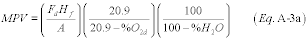
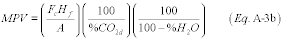
2.1.4.1 Maximum Potential Velocity and Flow RateFor this purpose, determine the span value of the flow monitor using the following procedure. Calculate the maximum potential velocity (MPV) using Equation A-3a or A-3b or determine the MPV (wet basis) from velocity traverse testing using Reference Method 2 (or its allowable alternatives) in appendix A to part 60 of this chapter. If using test values, use the highest average velocity (determined from the Method 2 traverses) measured at or near the maximum unit operating load (or, for units that do not produce electrical or thermal output, at the normal process operating conditions corresponding to the maximum stack gas flow rate). Express the MPV in units of wet standard feet per minute (fpm). For the purpose of providing substitute data during periods of missing flow rate data in accordance with §§ 75.31 and 75.33 and as required elsewhere in this part, calculate the maximum potential stack gas flow rate (MPF) in units of standard cubic feet per hour (scfh), as the product of the MPV (in units of wet, standard fpm) times 60, times the cross-sectional area of the stack or duct (in ft 2) at the flow monitor location.
 or
or
 Where:
MPV = maximum potential velocity (fpm, standard wet basis).
Fd = dry-basis F factor (dscf/mmBtu) from Table 1, Appendix F to this part.
Fc = carbon-based F factor (scf CO2/mmBtu) from Table 1, Appendix F to this part.
Hf = maximum heat input (mmBtu/minute) for all units, combined, exhausting to the stack or duct where the flow monitor is located.
A = inside cross sectional area (ft
2) of the flue at the flow monitor location.
%O2d = maximum oxygen concentration, percent dry basis, under normal operating conditions.
%CO2d = minimum carbon dioxide concentration, percent dry basis, under normal operating conditions.
%H2O = maximum percent flue gas moisture content under normal operating conditions.
2.1.4.2 Span Values and Range
Where:
MPV = maximum potential velocity (fpm, standard wet basis).
Fd = dry-basis F factor (dscf/mmBtu) from Table 1, Appendix F to this part.
Fc = carbon-based F factor (scf CO2/mmBtu) from Table 1, Appendix F to this part.
Hf = maximum heat input (mmBtu/minute) for all units, combined, exhausting to the stack or duct where the flow monitor is located.
A = inside cross sectional area (ft
2) of the flue at the flow monitor location.
%O2d = maximum oxygen concentration, percent dry basis, under normal operating conditions.
%CO2d = minimum carbon dioxide concentration, percent dry basis, under normal operating conditions.
%H2O = maximum percent flue gas moisture content under normal operating conditions.
2.1.4.2 Span Values and Range
Determine the span and range of the flow monitor as follows. Convert the MPV, as determined in section 2.1.4.1 of this appendix, to the same measurement units of flow rate that are used for daily calibration error tests (e.g., scfh, kscfh, kacfm, or differential pressure (inches of water)). Next, determine the “calibration span value” by multiplying the MPV (converted to equivalent daily calibration error units) by a factor no less than 1.00 and no greater than 1.25, and rounding up the result to at least two significant figures. For calibration span values in inches of water, retain at least two decimal places. Select appropriate reference signals for the daily calibration error tests as percentages of the calibration span value, as specified in section 2.2.2.1 of this appendix. Finally, calculate the “flow rate span value” (in scfh) as the product of the MPF, as determined in section 2.1.4.1 of this appendix, times the same factor (between 1.00 and 1.25) that was used to calculate the calibration span value. Round off the flow rate span value to the nearest 1000 scfh. Select the full-scale range of the flow monitor so that it is greater than or equal to the span value and is consistent with section 2.1 of this appendix. Include in the monitoring plan for the unit: calculations of the MPV, MPF, calibration span value, flow rate span value, and full-scale range (expressed both in scfh and, if different, in the measurement units of calibration).
2.1.4.3 Adjustment of Span and RangeFor each affected unit or common stack, the owner or operator shall make a periodic evaluation of the MPV, MPF, span, and range values for each flow rate monitor (at a minimum, an annual evaluation is required) and shall make any necessary span and range adjustments with corresponding monitoring plan updates, as described in paragraphs (a) through (c) of this section 2.1.4.3. Span and range adjustments may be required, for example, as a result of changes in the fuel supply, changes in the stack or ductwork configuration, changes in the manner of operation of the unit, or installation or removal of emission controls. In implementing the provisions in paragraphs (a) and (b) of this section 2.1.4.3, note that flow rate data recorded during short-term, non-representative operating conditions (e.g., a trial burn of a different type of fuel) shall be excluded from consideration. The owner or operator shall keep the results of the most recent span and range evaluation on-site, in a format suitable for inspection. Make each required span or range adjustment no later than 45 days after the end of the quarter in which the need to adjust the span or range is identified.
(a) If the fuel supply, stack or ductwork configuration, operating parameters, or other conditions change such that the maximum potential flow rate changes significantly, adjust the span and range to assure the continued accuracy of the flow monitor. A “significant” change in the MPV or MPF means that the guidelines of section 2.1 of this appendix can no longer be met, as determined by either a periodic evaluation by the owner or operator or from the results of an audit by the Administrator. The owner or operator should evaluate whether any planned changes in operation of the unit may affect the flow of the unit or stack and should plan any necessary span and range changes needed to account for these changes, so that they are made in as timely a manner as practicable to coordinate with the operational changes. Calculate the adjusted calibration span and flow rate span values using the procedures in section 2.1.4.2 of this appendix.
(b) Whenever the full-scale range is exceeded during a quarter, provided that the exceedance is not caused by a monitor out-of-control period, report 200.0 percent of the current full-scale range as the hourly flow rate for each hour of the full-scale exceedance. If the range is exceeded, make appropriate adjustments to the MPF, flow rate span, and range to prevent future full-scale exceedances. Calculate the new calibration span value by converting the new flow rate span value from units of scfh to units of daily calibration. A calibration error test must be performed and passed to validate data on the new range.
(c) Whenever changes are made to the MPV, MPF, full-scale range, or span value of the flow monitor, as described in paragraphs (a) and (b) of this section, record and report (as applicable) the new full-scale range setting, calculations of the flow rate span value, calibration span value, MPV, and MPF in an updated monitoring plan for the unit. The monitoring plan update shall be made in the quarter in which the changes become effective. Record and report the adjusted calibration span and reference values as parts of the records for the calibration error test required by appendix B to this part. Whenever the calibration span value is adjusted, use reference values for the calibration error test that meet the requirements of section 2.2.2.1 of this appendix, based on the most recent adjusted calibration span value. Perform a calibration error test according to section 2.1.1 of appendix B to this part whenever making a change to the flow monitor span or range, unless the range change also triggers a recertification under § 75.20(b).
2.1.5 Minimum Potential Moisture PercentageExcept as provided in section 2.1.6 of this appendix, the owner or operator of a unit that uses a continuous moisture monitoring system to correct emission rates and heat inputs from a dry basis to a wet basis (or vice-versa) shall, for the purpose of providing substitute data under § 75.37, use a default value of 3.0 percent H2O as the minimum potential moisture percentage. Alternatively, the minimum potential moisture percentage may be based upon 720 hours or more of quality-assured CEM data, representing the full operating load range of the unit(s). If this option is chosen, the minimum potential moisture percentage shall be the lowest quality-assured hourly average H2O concentration recorded in the 720 (or more) hours of data used for the determination.
2.1.6 Maximum Potential Moisture PercentageWhen Equation 19-3, 19-4 or 19-8 in Method 19 in appendix A to part 60 of this chapter is used to determine NOX emission rate, the owner or operator of a unit that uses a continuous moisture monitoring system shall, for the purpose of providing substitute data under § 75.37, determine the maximum potential moisture percentage. The maximum potential moisture percentage shall be based upon 720 hours or more of quality-assured CEM data, representing the full operating load range of the unit(s). The maximum potential moisture percentage shall be the highest quality-assured hourly average H2O concentration recorded in the 720 (or more) hours of data used for the determination. Alternatively, a default maximum potential moisture value of 15.0 percent H2O may be used.
2.2 Design for Quality Control Testing 2.2.1 Pollutant Concentration and CO2 or O2 Monitors(a) Design and equip each pollutant concentration and CO2 or O2 monitor with a calibration gas injection port that allows a check of the entire measurement system when calibration gases are introduced. For extractive and dilution type monitors, all monitoring components exposed to the sample gas, (e.g., sample lines, filters, scrubbers, conditioners, and as much of the probe as practicable) are included in the measurement system. For in situ type monitors, the calibration must check against the injected gas for the performance of all active electronic and optical components (e.g. transmitter, receiver, analyzer).
(b) Design and equip each pollutant concentration or CO2 or O2 monitor to allow daily determinations of calibration error (positive or negative) at the zero- and mid-or high-level concentrations specified in section 5.2 of this appendix.
2.2.2 Flow MonitorsDesign all flow monitors to meet the applicable performance specifications.
2.2.2.1 Calibration Error TestDesign and equip each flow monitor to allow for a daily calibration error test consisting of at least two reference values: Zero to 20 percent of span or an equivalent reference value (e.g., pressure pulse or electronic signal) and 50 to 70 percent of span. Flow monitor response, both before and after any adjustment, must be capable of being recorded by the data acquisition and handling system. Design each flow monitor to allow a daily calibration error test of the entire flow monitoring system, from and including the probe tip (or equivalent) through and including the data acquisition and handling system, or the flow monitoring system from and including the transducer through and including the data acquisition and handling system.
2.2.2.2 Interference Check(a) Design and equip each flow monitor with a means to ensure that the moisture expected to occur at the monitoring location does not interfere with the proper functioning of the flow monitoring system. Design and equip each flow monitor with a means to detect, on at least a daily basis, pluggage of each sample line and sensing port, and malfunction of each resistance temperature detector (RTD), transceiver or equivalent.
(b) Design and equip each differential pressure flow monitor to provide an automatic, periodic back purging (simultaneously on both sides of the probe) or equivalent method of sufficient force and frequency to keep the probe and lines sufficiently free of obstructions on at least a daily basis to prevent velocity sensing interference, and a means for detecting leaks in the system on at least a quarterly basis (manual check is acceptable).
(c) Design and equip each thermal flow monitor with a means to ensure on at least a daily basis that the probe remains sufficiently clean to prevent velocity sensing interference.
(d) Design and equip each ultrasonic flow monitor with a means to ensure on at least a daily basis that the transceivers remain sufficiently clean (e.g., backpurging system) to prevent velocity sensing interference.
3. Performance Specifications 3.1 Calibration Error(a) The calibration error performance specifications in this section apply only to 7-day calibration error tests under sections 6.3.1 and 6.3.2 of this appendix and to the offline calibration demonstration described in section 2.1.1.2 of appendix B to this part. The calibration error limits for daily operation of the continuous monitoring systems required under this part are found in section 2.1.4(a) of appendix B to this part.
(b) The calibration error of SO2 and NOX pollutant concentration monitors shall not deviate from the reference value of either the zero or upscale calibration gas by more than 2.5 percent of the span of the instrument, as calculated using Equation A-5 of this appendix. Alternatively, where the span value is less than 200 ppm, calibration error test results are also acceptable if the absolute value of the difference between the monitor response value and the reference value, |R−A| in Equation A-5 of this appendix, is ≤5 ppm. The calibration error of CO2 or O2 monitors (including O2 monitors used to measure CO2 emissions or percent moisture) shall not deviate from the reference value of the zero or upscale calibration gas by >0.5 percent O2 or CO2, as calculated using the term |R−A| in the numerator of Equation A-5 of this appendix. The calibration error of flow monitors shall not exceed 3.0 percent of the calibration span value of the instrument, as calculated using Equation A-6 of this appendix. For differential pressure-type flow monitors, the calibration error test results are also acceptable if |R−A|, the absolute value of the difference between the monitor response and the reference value in Equation A-6, does not exceed 0.01 inches of water.
3.2 Linearity CheckFor SO2 and NOX pollutant concentration monitors, the error in linearity for each calibration gas concentration (low-, mid-, and high-levels) shall not exceed or deviate from the reference value by more than 5.0 percent (as calculated using equation A-4 of this appendix). Linearity check results are also acceptable if the absolute value of the difference between the average of the monitor response values and the average of the reference values, | R-A | in equation A-4 of this appendix, is less than or equal to 5 ppm. For CO2 or O2 monitors (including O2 monitors used to measure CO2 emissions or percent moisture):
(1) The error in linearity for each calibration gas concentration (low-, mid-, and high-levels) shall not exceed or deviate from the reference value by more than 5.0 percent as calculated using equation A-4 of this appendix; or
(2) The absolute value of the difference between the average of the monitor response values and the average of the reference values, | R-A| in equation A-4 of this appendix, shall be less than or equal to 0.5 percent CO2 or O2, whichever is less restrictive.
3.3 Relative Accuracy 3.3.1 Relative Accuracy for SO2 Monitors(a) The relative accuracy for SO2 pollutant concentration monitors shall not exceed 10.0 percent except as provided in this section.
(b) For affected units where the average of the reference method measurements of SO2 concentration during the relative accuracy test audit is less than or equal to 250.0 ppm, the difference between the mean value of the monitor measurements and the reference method mean value shall not exceed ±15.0 ppm, wherever the relative accuracy specification of 10.0 percent is not achieved.
3.3.2 Relative Accuracy for NOX-Diluent Continuous Emission Monitoring Systems(a) The relative accuracy for NOX-diluent continuous emission monitoring systems shall not exceed 10.0 percent.
(b) For affected units where the average of the reference method measurements of NOX emission rate during the relative accuracy test audit is less than or equal to 0.200 lb/mmBtu, the difference between the mean value of the continuous emission monitoring system measurements and the reference method mean value shall not exceed ±0.020 lb/mmBtu, wherever the relative accuracy specification of 10.0 percent is not achieved.
3.3.3 Relative Accuracy for CO2 and O2 MonitorsThe relative accuracy for CO2 and O2 monitors shall not exceed 10.0 percent. The relative accuracy test results are also acceptable if the difference between the mean value of the CO2 or O2 monitor measurements and the corresponding reference method measurement mean value, calculated using equation A-7 of this appendix, does not exceed ±1.0 percent CO2 or O2.
3.3.4 Relative Accuracy for Flow Monitors(a) The relative accuracy of flow monitors shall not exceed 10.0 percent at any load (or operating) level at which a RATA is performed (i.e., the low, mid, or high level, as defined in section 6.5.2.1 of this appendix).
(b) For affected units where the average of the flow reference method measurements of gas velocity at a particular load (or operating) level of the relative accuracy test audit is less than or equal to 10.0 fps, the difference between the mean value of the flow monitor velocity measurements and the reference method mean value in fps at that level shall not exceed ±2.0 fps, wherever the 10.0 percent relative accuracy specification is not achieved.
3.3.5 Combined SO2/Flow Monitoring System [Reserved] 3.3.6 Relative Accuracy for Moisture Monitoring SystemsThe relative accuracy of a moisture monitoring system shall not exceed 10.0 percent. The relative accuracy test results are also acceptable if the difference between the mean value of the reference method measurements (in percent H2O) and the corresponding mean value of the moisture monitoring system measurements (in percent H2O), calculated using Equation A-7 of this appendix does not exceed ±1.5 percent H2O.
3.3.7 Relative Accuracy for NOX Concentration Monitoring Systems(a) The following requirement applies only to NOX concentration monitoring systems (i.e., NOX pollutant concentration monitors) that are used to determine NOX mass emissions, where the owner or operator elects to monitor and report NOX mass emissions using a NOX concentration monitoring system and a flow monitoring system.
(b) The relative accuracy for NOX concentration monitoring systems shall not exceed 10.0 percent. Alternatively, for affected units where the average of the reference method measurements of NOX concentration during the relative accuracy test audit is less than or equal to 250.0 ppm, the difference between the mean value of the continuous emission monitoring system measurements and the reference method mean value shall not exceed ±15.0 ppm, wherever the 10.0 percent relative accuracy specification is not achieved.
3.4 Bias 3.4.1 SO2 Pollutant Concentration Monitors, NOX Concentration Monitoring Systems and NOX-Diluent Continuous Emission Monitoring SystemsSO2 pollutant concentration monitors, NOX-diluent continuous emission monitoring systems and NOX concentration monitoring systems used to determine NOX mass emissions, as defined in § 75.71(a)(2), shall not be biased low as determined by the test procedure in section 7.6 of this appendix. The bias specification applies to all SO2 pollutant concentration monitors and to all NOX concentration monitoring systems, including those measuring an average SO2 or NOX concentration of 250.0 ppm or less, and to all NOX-diluent continuous emission monitoring systems, including those measuring an average NOX emission rate of 0.200 lb/mmBtu or less.
3.4.2 Flow MonitorsFlow monitors shall not be biased low as determined by the test procedure in section 7.6 of this appendix. The bias specification applies to all flow monitors including those measuring an average gas velocity of 10.0 fps or less.
3.5 Cycle TimeThe cycle time for pollutant concentration monitors, oxygen monitors used to determine percent moisture, and any other monitoring component of a continuous emission monitoring system that is required to perform a cycle time test shall not exceed 15 minutes.
4. Data Acquisition and Handling Systems(a) Automated data acquisition and handling systems shall read and record the entire range of pollutant concentrations and volumetric flow from zero through full-scale and provide a continuous, permanent record of all measurements and required information in an electronic format. These systems also shall have the capability of interpreting and converting the individual output signals from an SO2 pollutant concentration monitor, a flow monitor, a CO2 monitor, an O2 monitor, a NOX pollutant concentration monitor, a NOX-diluent CEMS, and a moisture monitoring system to produce a continuous readout of pollutant emission rates or pollutant mass emissions (as applicable) in the appropriate units (e.g., lb/hr, lb/mmBtu, tons/hr).
(b) Data acquisition and handling systems shall also compute and record: Monitor calibration error; any bias adjustments to SO2, NOX, flow rate, or NOX emission rate data; and all missing data procedure statistics specified in subpart D of this part.
(c) For an excepted monitoring system under appendix D or E of this part, data acquisition and handling systems shall:
(1) Read and record the full range of fuel flowrate through the upper range value;
(2) Calculate and record intermediate values necessary to obtain emissions, such as mass fuel flowrate and heat input rate;
(3) Calculate and record emissions in the appropriate units (e.g., lb/hr of SO2, lb/mmBtu of NOX);
(4) Predict and record NOX emission rate using the heat input rate and the NOX/heat input correlation developed under appendix E of this part;
(5) Calculate and record all missing data substitution values specified in appendix D or E of this part; and
(6) Provide a continuous, permanent record of all measurements and required information in an electronic format.
5. Calibration Gas 5.1 Reference GasesFor the purposes of part 75, calibration gases include the following:
5.1.1 Standard Reference Materials (SRM)These calibration gases may be obtained from the National Institute of Standards and Technology (NIST) at the following address: Quince Orchard and Cloppers Road, Gaithersburg, MD 20899-0001.
5.1.2 SRM-Equivalent Compressed Gas Primary Reference Material (PRM)Contact the Gas Metrology Team, Analytical Chemistry Division, Chemical Science and Technology Laboratory of NIST, at the address in section 5.1.1, for a list of vendors and cylinder gases.
5.1.3 NIST Traceable Reference MaterialsContact the Gas Metrology Team, Analytical Chemistry Division, Chemical Science and Technology Laboratory of NIST, at the address in section 5.1.1, for a list of vendors and cylinder gases that meet the definition for a NIST Traceable Reference Material (NTRM) provided in § 72.2.
5.1.4 EPA Protocol Gases(a) An EPA Protocol gas is a calibration gas mixture prepared and analyzed according to Section 2 of the “EPA Traceability Protocol for Assay and Certification of Gaseous Calibration Standards,” September 1997, as amended on August 25, 1999, EPA-600/R-97/121 (incorporated by reference, see § 75.6) or such revised procedure as approved by the Administrator.
(b) EPA Protocol gas concentrations must be certified by an EPA Protocol gas production site to have an analytical uncertainty (95-percent confidence interval) to be not more than plus or minus 2.0 percent (inclusive) of the certified concentration (tag value) of the gas mixture. The uncertainty must be calculated using the statistical procedures (or equivalent statistical techniques) that are listed in Section 2.1.8 of the “EPA Traceability Protocol for Assay and Certification of Gaseous Calibration Standards,” September 1997, as amended on August 25, 1999, EPA-600/R-97/121 (incorporated by reference, see § 75.6).
5.1.5 Research Gas MixturesConcentrations of research gas mixtures, as defined in § 72.2 of this chapter, must be certified by the National Institute of Standards and Technology to have an analytical uncertainty (95-percent confidence interval) calculated using the statistical procedures (or equivalent statistical techniques) that are listed in Section 2.1.8 of the “EPA Traceability Protocol for Assay and Certification of Gaseous Calibration Standards,” September 1997, as amended on August 25, 1999, EPA-600/R-97/121 (incorporated by reference, see § 75.6) to be not more than plus or minus 2.0 percent (inclusive) of the concentration specified on the cylinder label (i.e., the tag value) in order to be used as calibration gas under this part. Inquiries about the RGM program should be directed to: National Institute of Standards and Technology, Analytical Chemistry Division, Chemical Science and Technology Laboratory, B-324 Chemistry, Gaithersburg, MD 20899.
5.1.6 Zero Air MaterialZero air material is defined in § 72.2 of this chapter.
5.1.7 NIST/EPA-Approved Certified Reference MaterialsExisting certified reference materials (CRMs) that are still within their certification period may be used as calibration gas.
5.1.8 Gas Manufacturer's Intermediate StandardsGas manufacturer's intermediate standards is defined in § 72.2 of this chapter.
5.2 ConcentrationsFour concentration levels are required as follows.
5.2.1 Zero-level Concentration0.0 to 20.0 percent of span, including span for high-scale or both low- and high-scale for SO2, NOX, CO2, and O2 monitors, as appropriate.
5.2.2 Low-level Concentration20.0 to 30.0 percent of span, including span for high-scale or both low- and high-scale for SO2, NOX, CO2, and O2 monitors, as appropriate.
5.2.3 Mid-level Concentration50.0 to 60.0 percent of span, including span for high-scale or both low- and high-scale for SO2, NOX, CO2, and O2 monitors, as appropriate.
5.2.4 High-level Concentration80.0 to 100.0 percent of span, including span for high-scale or both low-and high-scale for SO2, NOX, CO2, and O2 monitors, as appropriate.
6. Certification Tests and Procedures 6.1 General Requirements 6.1.1 Pretest PreparationInstall the components of the continuous emission monitoring system (i.e., pollutant concentration monitors, CO2 or O2 monitor, and flow monitor) as specified in sections 1, 2, and 3 of this appendix, and prepare each system component and the combined system for operation in accordance with the manufacturer's written instructions. Operate the unit(s) during each period when measurements are made. Units may be tested on non-consecutive days. To the extent practicable, test the DAHS software prior to testing the monitoring hardware.
6.1.2 Requirements for Air Emission Testing(a) On and after March 27, 2012, all relative accuracy test audits (RATAs) of CEMS under this part, and stack testing under § 75.19 and Appendix E to this part shall be conducted by an Air Emission Testing Body (AETB) which has provided to the owner or operator of a unit subject to this part the documentation required in paragraph (b) of this section, demonstrating its conformance to ASTM D7036-04 (incorporated by reference, see § 75.6).
(b) The owner or operator shall obtain from the AETB a certification that as of the time of testing the AETB is operating in conformance with ASTM D7036-04 (incorporated by reference, see § 75.6). The AETB's certification may be limited in scope to the tests identified under paragraph (a). The AETB's certification need not extend to other work it may perform. This certification shall be provided in the form of either:
(1) A certificate of accreditation or interim accreditation for the relevant test methods issued by a recognized, national accreditation body; or
(2) A letter of certification for the relevant test methods signed by a member of the senior management staff of the AETB.
(c) The owner or operator shall obtain from the AETB the information required under §§ 75.59(a)(15), (b)(6), and (d)(4), as applicable.
(d) While under no obligation to request the following information from an AETB, to review the information provided by the AETB in response to such a request, or to take any other action related to the response, the owner or operator may find it useful to request that AETBs complying with paragraph (b)(2) of this section provide a copy of the following:
(1) The AETB's quality manual. For the purpose of application of 40 CFR part 2, subpart B, AETB's concerned about the potential for public access to confidential business information (CBI) may identify any information subject to such a claim in the copy provided;
(2) The results of any internal audits performed by the AETB and any external audits of the AETB during the 12 month period through the previous calendar quarter;
(3) Performance data (as defined in ASTM D7036-04 (incorporated by reference, see § 75.6)) collected by the AETB, including corrective actions implemented, during the 12 month period through the previous calendar quarter; and
(4) Training records for all on-site technical personnel, including any Qualified Individuals, for the 12 month period through the previous calendar quarter.
(e) All relative accuracy testing performed pursuant to § 75.74(c)(2)(ii), section 6.5 of appendix A to this part or section 2.3.1 of appendix B to this part, and stack testing under § 75.19 and Appendix E to this part shall be overseen and supervised on site by at least one Qualified Individual, as defined in § 72.2 of this chapter with respect to the methods employed in the test project. If the source owner or operator, or a State, local, or EPA observer, discovers while the test team is still on site, that at least one QI did not oversee and supervise the entire test (as qualified by this paragraph (e)), only those portions of the test that were overseen and supervised by at least one QI as described above may be used under this part. However, allowance is made for normal activities of a QI who is overseeing and supervising a test, e.g., bathroom breaks, meal breaks, and emergencies that may arise during a test.
(f) Except as provided in paragraph (e), no RATA performed pursuant to § 75.74(c)(2)(ii), section 6.5 of appendix A to this part or section 2.3.1 of appendix B to this part, and no stack test under § 75.19 or Appendix E to this part (or portion of such a RATA or stack test) conducted by an AETB (as defined in § 72.2) shall be invalidated under this part as a result of the failure of the AETB to conform to ASTM D7036-04 (incorporated by reference, see § 75.6). Validation of such tests is determined based on the other part 75 testing requirements. EPA recommends that proper observation of tests and review of test results continue, regardless of whether an AETB fully conforms to ASTM D7036-04.
(g) An owner or operator who has requested information from an AETB under paragraph (d) of this part who believes that the information provided by the AETB was either incomplete or inaccurate may request the Administrator's assistance in remedying the alleged deficiencies. Upon such a request, if the Administrator concurs that the information submitted to a source subject to part 75 by an AETB under this section is either incomplete or inaccurate, the Administrator will provide the AETB a description of the deficiencies to be remedied. The Administrator's determination of completeness and accuracy of information will be solely based on the provisions of ASTM D7036-04 (incorporated by reference, see § 75.6) and this part. The Administrator may post the name of the offending AETB on Agency Web sites (including the CAMD Web site http://www.epa.gov/airmarkets/emissions/aetb.html) if within 30 days of the Administrator having provided the AETB a description of the deficiencies to be remedied, the AETB does not satisfactorily respond to the source and notify the Administrator of the response by submitting the notification to [email protected], unless otherwise provided by the Administrator. The AETB need not submit the information it provides to the owner or operator to the Administrator, unless specifically requested by the Administrator. If after the AETB's name is posted, the Administrator, in consultation with the source, determines that the AETB's response is sufficient, the AETB's name will be removed from the EPA Web sites.
6.2 Linearity Check (General Procedures)Check the linearity of each SO2, NOX, CO2, and O2 monitor while the unit, or group of units for a common stack, is combusting fuel at conditions of typical stack temperature and pressure; it is not necessary for the unit to be generating electricity during this test. Notwithstanding these requirements, if the SO2 or NOX span value for a particular monitor range is ≤30 ppm, that range is exempted from the linearity check requirements of this part, for initial certification, recertification, and for on-going quality-assurance. For units with two measurement ranges (high and low) for a particular parameter, perform a linearity check on both the low scale (except for SO2 or NOX span values ≤30 ppm) and the high scale. Note that for a NOX-diluent monitoring system with two NOX measurement ranges, if the low NOX scale has a span value ≤30 ppm and is exempt from linearity checks, this does not exempt either the diluent monitor or the high NOX scale (if the span is >30 ppm) from linearity check requirements. For on-going quality assurance of the CEMS, perform linearity checks, using the procedures in this section, on the range(s) and at the frequency specified in section 2.2.1 of appendix B to this part. Challenge each monitor with calibration gas, as defined in section 5.1 of this appendix, at the low-, mid-, and high-range concentrations specified in section 5.2 of this appendix. Introduce the calibration gas at the gas injection port, as specified in section 2.2.1 of this appendix. Operate each monitor at its normal operating temperature and conditions. For extractive and dilution type monitors, pass the calibration gas through all filters, scrubbers, conditioners, and other monitor components used during normal sampling and through as much of the sampling probe as is practical. For in-situ type monitors, perform calibration checking all active electronic and optical components, including the transmitter, receiver, and analyzer. Challenge the monitor three times with each reference gas (see example data sheet in Figure 1). Do not use the same gas twice in succession. To the extent practicable, the duration of each linearity test, from the hour of the first injection to the hour of the last injection, shall not exceed 24 unit operating hours. Record the monitor response from the data acquisition and handling system. For each concentration, use the average of the responses to determine the error in linearity using Equation A-4 in this appendix. Linearity checks are acceptable for monitor or monitoring system certification, recertification, or quality assurance if none of the test results exceed the applicable performance specifications in section 3.2 of this appendix. The status of emission data from a CEMS prior to and during a linearity test period shall be determined as follows:
(a) For the initial certification of a CEMS, data from the monitoring system are considered invalid until all certification tests, including the linearity test, have been successfully completed, unless the conditional data validation procedures in § 75.20(b)(3) are used. When the procedures in § 75.20(b)(3) are followed, the words “initial certification” apply instead of “recertification,” and complete all of the initial certification tests by the applicable deadline in § 75.4, rather than within the time periods specified in § 75.20(b)(3)(iv) for the individual tests.
(b) For the routine quality assurance linearity checks required by section 2.2.1 of appendix B to this part, use the data validation procedures in section 2.2.3 of appendix B to this part.
(c) When a linearity test is required as a diagnostic test or for recertification, use the data validation procedures in § 75.20(b)(3).
(d) For linearity tests of non-redundant backup monitoring systems, use the data validation procedures in § 75.20(d)(2)(iii).
(e) For linearity tests performed during a grace period and after the expiration of a grace period, use the data validation procedures in sections 2.2.3 and 2.2.4, respectively, of appendix B to this part.
(f) For all other linearity checks, use the data validation procedures in section 2.2.3 of appendix B to this part.
6.3 7-Day Calibration Error Test 6.3.1 Gas Monitor 7-Day Calibration Error TestThe following monitors and ranges are exempted from the 7-day calibration error test requirements of this part: the SO2, NOX, CO2 and O2 monitors installed on peaking units (as defined in § 72.2 of this chapter); and any SO2 or NOX measurement range with a span value of 50 ppm or less. In all other cases, measure the calibration error of each SO2 monitor, each NOX monitor, and each CO2 or O2 monitor while the unit is combusting fuel (but not necessarily generating electricity) once each day for 7 consecutive operating days according to the following procedures. (In the event that unit outages occur after the commencement of the test, the 7 consecutive unit operating days need not be 7 consecutive calendar days). Units using dual span monitors must perform the calibration error test on both high- and low-scales of the pollutant concentration monitor. The calibration error test procedures in this section and in section 6.3.2 of this appendix shall also be used to perform the daily assessments and additional calibration error tests required under sections 2.1.1 and 2.1.3 of appendix B to this part. Do not make manual or automatic adjustments to the monitor settings until after taking measurements at both zero and high concentration levels for that day during the 7-day test. If automatic adjustments are made following both injections, conduct the calibration error test such that the magnitude of the adjustments can be determined and recorded. Record and report test results for each day using the unadjusted concentration measured in the calibration error test prior to making any manual or automatic adjustments (i.e., resetting the calibration). The calibration error tests should be approximately 24 hours apart, (unless the 7-day test is performed over nonconsecutive days). Perform calibration error tests at both the zero-level concentration and high-level concentration, as specified in section 5.2 of this appendix. Alternatively, a mid-level concentration gas (50.0 to 60.0 percent of the span value) may be used in lieu of the high-level gas, provided that the mid-level gas is more representative of the actual stack gas concentrations. A calibration gas blend may be used as both a zero-level gas and an upscale (mid- or high-level) gas, where appropriate. In addition, repeat the procedure for SO2 and NOX pollutant concentration monitors using the low-scale for units equipped with emission controls or other units with dual span monitors. Use only calibration gas, as specified in section 5.1 of this appendix. Introduce the calibration gas at the gas injection port, as specified in section 2.2.1 of this appendix. Operate each monitor in its normal sampling mode. For extractive and dilution type monitors, pass the calibration gas through all filters, scrubbers, conditioners, and other monitor components used during normal sampling and through as much of the sampling probe as is practical. For in-situ type monitors, perform calibration, checking all active electronic and optical components, including the transmitter, receiver, and analyzer. Challenge the pollutant concentration monitors and CO2 or O2 monitors once with each calibration gas. Record the monitor response from the data acquisition and handling system. Using Equation A-5 of this appendix, determine the calibration error at each concentration once each day (at approximately 24-hour intervals) for 7 consecutive days according to the procedures given in this section. The results of a 7-day calibration error test are acceptable for monitor or monitoring system certification, recertification or diagnostic testing if none of these daily calibration error test results exceed the applicable performance specifications in section 3.1 of this appendix. The status of emission data from a gas monitor prior to and during a 7-day calibration error test period shall be determined as follows:
(a) For initial certification, data from the monitor are considered invalid until all certification tests, including the 7-day calibration error test, have been successfully completed, unless the conditional data validation procedures in § 75.20(b)(3) are used. When the procedures in § 75.20(b)(3) are followed, the words “initial certification” apply instead of “recertification,” and complete all of the initial certification tests by the applicable deadline in § 75.4, rather than within the time periods specified in § 75.20(b)(3)(iv) for the individual tests.
(b) When a 7-day calibration error test is required as a diagnostic test or for recertification, use the data validation procedures in § 75.20(b)(3).
6.3.2 Flow Monitor 7-day Calibration Error TestFlow monitors installed on peaking units (as defined in § 72.2 of this chapter) are exempted from the 7-day calibration error test requirements of this part. In all other cases, perform the 7-day calibration error test of a flow monitor, when required for certification, recertification or diagnostic testing, according to the following procedures. Introduce the reference signal corresponding to the values specified in section 2.2.2.1 of this appendix to the probe tip (or equivalent), or to the transducer. During the 7-day certification test period, conduct the calibration error test while the unit is operating once each unit operating day (as close to 24-hour intervals as practicable). In the event that unit outages occur after the commencement of the test, the 7 consecutive operating days need not be 7 consecutive calendar days. Record the flow monitor responses by means of the data acquisition and handling system. Calculate the calibration error using Equation A-6 of this appendix. Do not perform any corrective maintenance, repair, or replacement upon the flow monitor during the 7-day test period other than that required in the quality assurance/quality control plan required by appendix B to this part. Do not make adjustments between the zero and high reference level measurements on any day during the 7-day test. If the flow monitor operates within the calibration error performance specification (i.e., less than or equal to 3.0 percent error each day and requiring no corrective maintenance, repair, or replacement during the 7-day test period), the flow monitor passes the calibration error test. Record all maintenance activities and the magnitude of any adjustments. Record output readings from the data acquisition and handling system before and after all adjustments. Record and report all calibration error test results using the unadjusted flow rate measured in the calibration error test prior to resetting the calibration. Record all adjustments made during the 7-day period at the time the adjustment is made, and report them in the certification or recertification application. The status of emissions data from a flow monitor prior to and during a 7-day calibration error test period shall be determined as follows:
(a) For initial certification, data from the monitor are considered invalid until all certification tests, including the 7-day calibration error test, have been successfully completed, unless the conditional data validation procedures in § 75.20(b)(3) are used. When the procedures in § 75.20(b)(3) are followed, the words “initial certification” apply instead of “recertification,” and complete all of the initial certification tests by the applicable deadline in § 75.4, rather than within the time periods specified in § 75.20(b)(3)(iv) for the individual tests.
(b) When a 7-day calibration error test is required as a diagnostic test or for recertification, use the data validation procedures in § 75.20(b)(3).
6.3.3 For gas or flow monitors installed on peaking units, the exemption from performing the 7-day calibration error test applies as long as the unit continues to meet the definition of a peaking unit in § 72.2 of this chapter. However, if at the end of a particular calendar year or ozone season, it is determined that peaking unit status has been lost, the owner or operator shall perform a diagnostic 7-day calibration error test of each monitor installed on the unit, by no later than December 31 of the following calendar year.
6.4 Cycle Time TestPerform cycle time tests for each pollutant concentration monitor and continuous emission monitoring system while the unit is operating, according to the following procedures. Use a zero-level and a high-level calibration gas (as defined in section 5.2 of this appendix) alternately. To determine the downscale cycle time, measure the concentration of the flue gas emissions until the response stabilizes. Record the stable emissions value. Inject a zero-level concentration calibration gas into the probe tip (or injection port leading to the calibration cell, for in situ systems with no probe). Record the time of the zero gas injection, using the data acquisition and handling system (DAHS). Next, allow the monitor to measure the concentration of the zero gas until the response stabilizes. Record the stable ending calibration gas reading. Determine the downscale cycle time as the time it takes for 95.0 percent of the step change to be achieved between the stable stack emissions value and the stable ending zero gas reading. Then repeat the procedure, starting with stable stack emissions and injecting the high-level gas, to determine the upscale cycle time, which is the time it takes for 95.0 percent of the step change to be achieved between the stable stack emissions value and the stable ending high-level gas reading. Use the following criteria to assess when a stable reading of stack emissions or calibration gas concentration has been attained. A stable value is equivalent to a reading with a change of less than 2.0 percent of the span value for 2 minutes, or a reading with a change of less than 6.0 percent from the measured average concentration over 6 minutes. Alternatively, the reading is considered stable if it changes by no more than 0.5 ppm or 0.2% CO2 or O2 (as applicable) for two minutes. (Owners or operators of systems which do not record data in 1-minute or 3-minute intervals may petition the Administrator under § 75.66 for alternative stabilization criteria). For monitors or monitoring systems that perform a series of operations (such as purge, sample, and analyze), time the injections of the calibration gases so they will produce the longest possible cycle time. Refer to Figures 6a and 6b in this appendix for example calculations of upscale and downscale cycle times. Report the slower of the two cycle times (upscale or downscale) as the cycle time for the analyzer. Prior to January 1, 2009 for the NOX-diluent continuous emission monitoring system test, either record and report the longer cycle time of the two component analyzers as the system cycle time or record the cycle time for each component analyzer separately (as applicable). On and after January 1, 2009, record the cycle time for each component analyzer separately. For time-shared systems, perform the cycle time tests at each probe locations that will be polled within the same 15-minute period during monitoring system operations. To determine the cycle time for time-shared systems, at each monitoring location, report the sum of the cycle time observed at that monitoring location plus the sum of the time required for all purge cycles (as determined by the continuous emission monitoring system manufacturer) at each of the probe locations of the time-shared systems. For monitors with dual ranges, report the test results for each range separately. Cycle time test results are acceptable for monitor or monitoring system certification, recertification or diagnostic testing if none of the cycle times exceed 15 minutes. The status of emissions data from a monitor prior to and during a cycle time test period shall be determined as follows:
(a) For initial certification, data from the monitor are considered invalid until all certification tests, including the cycle time test, have been successfully completed, unless the conditional data validation procedures in § 75.20(b)(3) are used. When the procedures in § 75.20(b)(3) are followed, the words “initial certification” apply instead of “recertification,” and complete all of the initial certification tests by the applicable deadline in § 75.4, rather than within the time periods specified in § 75.20(b)(3)(iv) for the individual tests.
(b) When a cycle time test is required as a diagnostic test or for recertification, use the data validation procedures in § 75.20(b)(3).
6.5 Relative Accuracy and Bias Tests (General Procedures)Perform the required relative accuracy test audits (RATAs) as follows for each CO2 emissions concentration monitor (including O2 monitors used to determine CO2 emissions concentration), each SO2 pollutant concentration monitor, each NOX concentration monitoring system used to determine NOX mass emissions, each flow monitor, each NOX-diluent CEMS, each O2 or CO2 diluent monitor used to calculate heat input, and each moisture monitoring system. For NOX concentration monitoring systems used to determine NOX mass emissions, as defined in § 75.71(a)(2), use the same general RATA procedures as for SO2 pollutant concentration monitors; however, use the reference methods for NOX concentration specified in section 6.5.10 of this appendix:
(a) Except as otherwise provided in this paragraph or in § 75.21(a)(5), perform each RATA while the unit (or units, if more than one unit exhausts into the flue) is combusting the fuel that is a normal primary or backup fuel for that unit (for some units, more than one type of fuel may be considered normal, e.g., a unit that combusts gas or oil on a seasonal basis). For units that co-fire fuels as the predominant mode of operation, perform the RATAs while co-firing. For Hg monitoring systems, perform the RATAs while the unit is combusting coal. When relative accuracy test audits are performed on CEMS installed on bypass stacks/ducts, use the fuel normally combusted by the unit (or units, if more than one unit exhausts into the flue) when emissions exhaust through the bypass stack/ducts.
(b) Perform each RATA at the load (or operating) level(s) specified in section 6.5.1 or 6.5.2 of this appendix or in section 2.3.1.3 of appendix B to this part, as applicable.
(c) For monitoring systems with dual ranges, perform the relative accuracy test on the range normally used for measuring emissions. For units with add-on SO2 or NOX controls that operate continuously rather than seasonally, or for units that need a dual range to record high concentration “spikes” during startup conditions, the low range is considered normal. However, for some dual span units (e.g., for units that use fuel switching or for which the emission controls are operated seasonally), provided that both monitor ranges are connected to a common probe and sample interface, either of the two measurement ranges may be considered normal; in such cases, perform the RATA on the range that is in use at the time of the scheduled test. If the low and high measurement ranges are connected to separate sample probes and interfaces, RATA testing on both ranges is required.
(d) Record monitor or monitoring system output from the data acquisition and handling system.
(e) Complete each single-load relative accuracy test audit within a period of 168 consecutive unit operating hours, as defined in § 72.2 of this chapter (or, for CEMS installed on common stacks or bypass stacks, 168 consecutive stack operating hours, as defined in § 72.2 of this chapter). For 2-level and 3-level flow monitor RATAs, complete all of the RATAs at all levels, to the extent practicable, within a period of 168 consecutive unit (or stack) operating hours; however, if this is not possible, up to 720 consecutive unit (or stack) operating hours may be taken to complete a multiple-load flow RATA.
(f) The status of emission data from the CEMS prior to and during the RATA test period shall be determined as follows:
(1) For the initial certification of a CEMS, data from the monitoring system are considered invalid until all certification tests, including the RATA, have been successfully completed, unless the conditional data validation procedures in § 75.20(b)(3) are used. When the procedures in § 75.20(b)(3) are followed, the words “initial certification” apply instead of “recertification,” and complete all of the initial certification tests by the applicable deadline in § 75.4, rather than within the time periods specified in § 75.20(b)(3)(iv) for the individual tests.
(2) For the routine quality assurance RATAs required by section 2.3.1 of appendix B to this part, use the data validation procedures in section 2.3.2 of appendix B to this part.
(3) For recertification RATAs, use the data validation procedures in § 75.20(b)(3).
(4) For quality assurance RATAs of non-redundant backup monitoring systems, use the data validation procedures in §§ 75.20(d)(2)(v) and (vi).
(5) For RATAs performed during and after the expiration of a grace period, use the data validation procedures in sections 2.3.2 and 2.3.3, respectively, of appendix B to this part.
(6) For all other RATAs, use the data validation procedures in section 2.3.2 of appendix B to this part.
(g) For each SO2 or CO2 emissions concentration monitor, each flow monitor, each CO2 or O2 diluent monitor used to determine heat input, each NOX concentration monitoring system used to determine NOX mass emissions, as defined in § 75.71(a)(2), each moisture monitoring system, and each NOX-diluent CEMS, calculate the relative accuracy, in accordance with section 7.3 or 7.4 of this appendix, as applicable. In addition (except for CO2, O2, or moisture monitors), test for bias and determine the appropriate bias adjustment factor, in accordance with sections 7.6.4 and 7.6.5 of this appendix, using the data from the relative accuracy test audits.
6.5.1 Gas Monitoring System RATAs (Special Considerations)(a) Perform the required relative accuracy test audits for each SO2 or CO2 emissions concentration monitor, each CO2 or O2 diluent monitor used to determine heat input, each NOX-diluent CEMS, and each NOX concentration monitoring system used to determine NOX mass emissions, as defined in § 75.71(a)(2), at the normal load level or normal operating level for the unit (or combined units, if common stack), as defined in section 6.5.2.1 of this appendix. If two load levels or operating levels have been designated as normal, the RATAs may be done at either load (or operating) level.
(b) For the initial certification of a gas monitoring system and for recertifications in which, in addition to a RATA, one or more other tests are required (i.e., a linearity test, cycle time test, or 7-day calibration error test), EPA recommends that the RATA not be commenced until the other required tests of the CEMS have been passed.
6.5.2 Flow Monitor RATAs (Special Considerations)(a) Except as otherwise provided in paragraph (b) or (e) of this section, perform relative accuracy test audits for the initial certification of each flow monitor at three different exhaust gas velocities (low, mid, and high), corresponding to three different load levels or operating levels within the range of operation, as defined in section 6.5.2.1 of this appendix. For a common stack/duct, the three different exhaust gas velocities may be obtained from frequently used unit/load or operating level combinations for the units exhausting to the common stack. Select the three exhaust gas velocities such that the audit points at adjacent load or operating levels (i.e., low and mid or mid and high), in megawatts (or in thousands of lb/hr of steam production or in ft/sec, as applicable), are separated by no less than 25.0 percent of the range of operation, as defined in section 6.5.2.1 of this appendix.
(b) For flow monitors on bypass stacks/ducts and peaking units, the flow monitor relative accuracy test audits for initial certification and recertification shall be single-load tests, performed at the normal load, as defined in section 6.5.2.1(d) of this appendix.
(c) Flow monitor recertification RATAs shall be done at three load level(s) (or three operating levels), unless otherwise specified in paragraph (b) or (e) of this section or unless otherwise specified or approved by the Administrator.
(d) The semiannual and annual quality assurance flow monitor RATAs required under appendix B to this part shall be done at the load level(s) (or operating levels) specified in section 2.3.1.3 of appendix B to this part.
(e) For flow monitors installed on units that do not produce electrical or thermal output, the flow RATAs for initial certification or recertification may be done at fewer than three operating levels, if:
(1) The owner or operator provides a technical justification in the hardcopy portion of the monitoring plan for the unit required under § 75.53(e)(2), demonstrating that the unit operates at only one level or two levels during normal operation (excluding unit startup and shutdown). Appropriate documentation and data must be provided to support the claim of single-level or two-level operation; and
(2) The justification provided in paragraph (e)(1) of this section is deemed to be acceptable by the permitting authority.
6.5.2.1 Range of Operation and Normal Load (or Operating) Level(s)(a) The owner or operator shall determine the upper and lower boundaries of the “range of operation” as follows for each unit (or combination of units, for common stack configurations):
(1) For affected units that produce electrical output (in megawatts) or thermal output (in klb/hr of steam production or mmBtu/hr), the lower boundary of the range of operation of a unit shall be the minimum safe, stable loads for any of the units discharging through the stack. Alternatively, for a group of frequently-operated units that serve a common stack, the sum of the minimum safe, stable loads for the individual units may be used as the lower boundary of the range of operation. The upper boundary of the range of operation of a unit shall be the maximum sustainable load. The “maximum sustainable load” is the higher of either: the nameplate or rated capacity of the unit, less any physical or regulatory limitations or other deratings; or the highest sustainable load, based on at least four quarters of representative historical operating data. For common stacks, the maximum sustainable load is the sum of all of the maximum sustainable loads of the individual units discharging through the stack, unless this load is unattainable in practice, in which case use the highest sustainable combined load for the units that discharge through the stack. Based on at least four quarters of representative historical operating data. The load values for the unit(s) shall be expressed either in units of megawatts of thousands of lb/hr of steam load or mmBtu/hr of thermal output; or
(2) For affected units that do not produce electrical or thermal output, the lower boundary of the range of operation shall be the minimum expected flue gas velocity (in ft/sec) during normal, stable operation of the unit. The upper boundary of the range of operation shall be the maximum potential flue gas velocity (in ft/sec) as defined in section 2.1.4.1 of this appendix. The minimum expected and maximum potential velocities may be derived from the results of reference method testing or by using Equation A-3a or A-3b (as applicable) in section 2.1.4.1 of this appendix. If Equation A-3a or A-3b is used to determine the minimum expected velocity, replace the word “maximum” with the word “minimum” in the definitions of “MPV,” “Hf,” “% O2d,” and “% H2O,” and replace the word “minimum” with the word “maximum” in the definition of “CO2d.” Alternatively, 0.0 ft/sec may be used as the lower boundary of the range of operation.
(b) The operating levels for relative accuracy test audits shall, except for peaking units, be defined as follows: the “low” operating level shall be the first 30.0 percent of the range of operation; the “mid” operating level shall be the middle portion (>30.0 percent, but ≤60.0 percent) of the range of operation; and the “high” operating level shall be the upper end (>60.0 percent) of the range of operation. For example, if the upper and lower boundaries of the range of operation are 100 and 1100 megawatts, respectively, then the low, mid, and high operating levels would be 100 to 400 megawatts, 400 to 700 megawatts, and 700 to 1100 megawatts, respectively.
(c) Units that do not produce electrical or thermal output are exempted from the requirements of this paragraph, (c). The owner or operator shall identify, for each affected unit or common stack (except for peaking units and units using the low mass emissions (LME) excepted methodology under § 75.19), the “normal” load level or levels (low, mid or high), based on the operating history of the unit(s). To identify the normal load level(s), the owner or operator shall, at a minimum, determine the relative number of operating hours at each of the three load levels, low, mid and high over the past four representative operating quarters. The owner or operator shall determine, to the nearest 0.1 percent, the percentage of the time that each load level (low, mid, high) has been used during that time period. A summary of the data used for this determination and the calculated results shall be kept on-site in a format suitable for inspection. For new units or newly-affected units, the data analysis in this paragraph may be based on fewer than four quarters of data if fewer than four representative quarters of historical load data are available. Or, if no historical load data are available, the owner or operator may designate the normal load based on the expected or projected manner of operating the unit. However, in either case, once four quarters of representative data become available, the historical load analysis shall be repeated.
(d) Determination of normal load (or operating level)
(1) Based on the analysis of the historical load data described in paragraph (c) of this section, the owner or operator shall, for units that produce electrical or thermal output, designate the most frequently used load level as the normal load level for the unit (or combination of units, for common stacks). The owner or operator may also designate the second most frequently used load level as an additional normal load level for the unit or stack. For peaking units and LME units, normal load designations are unnecessary; the entire operating load range shall be considered normal. If the manner of operation of the unit changes significantly, such that the designated normal load(s) or the two most frequently used load levels change, the owner or operator shall repeat the historical load analysis and shall redesignate the normal load(s) and the two most frequently used load levels, as appropriate. A minimum of two representative quarters of historical load data are required to document that a change in the manner of unit operation has occurred. Update the electronic monitoring plan whenever the normal load level(s) and the two most frequently-used load levels are redesignated.
(2) For units that do not produce electrical or thermal output, the normal operating level(s) shall be determined using sound engineering judgment, based on knowledge of the unit and operating experience with the industrial process.
(e) The owner or operator shall report the upper and lower boundaries of the range of operation for each unit (or combination of units, for common stacks), in units of megawatts or thousands of lb/hr or mmBtu/hr of steam production or ft/sec (as applicable), in the electronic monitoring plan required under § 75.53. Except for peaking units and LME units, the owner or operator shall indicate, in the electronic monitoring plan, the load level (or levels) designated as normal under this section and shall also indicate the two most frequently used load levels.
6.5.2.2 Multi-Load (or Multi-Level) Flow RATA ResultsFor each multi-load (or multi-level) flow RATA, calculate the flow monitor relative accuracy at each operating level. If a flow monitor relative accuracy test is failed or aborted due to a problem with the monitor on any level of a 2-level (or 3-level) relative accuracy test audit, the RATA must be repeated at that load (or operating) level. However, the entire 2-level (or 3-level) relative accuracy test audit does not have to be repeated unless the flow monitor polynomial coefficients or K-factor(s) are changed, in which case a 3-level RATA is required (or, a 2-level RATA, for units demonstrated to operate at only two levels, under section 6.5.2(e) of this appendix).
6.5.3 [Reserved] 6.5.4 CalculationsUsing the data from the relative accuracy test audits, calculate relative accuracy and bias in accordance with the procedures and equations specified in section 7 of this appendix.
6.5.5 Reference Method Measurement LocationSelect a location for reference method measurements that is (1) accessible; (2) in the same proximity as the monitor or monitoring system location; and (3) meets the requirements of Performance Specification 2 in appendix B of part 60 of this chapter for SO2 and NOX continuous emission monitoring systems, Performance Specification 3 in appendix B of part 60 of this chapter for CO2 or O2 monitors, or method 1 (or 1A) in appendix A of part 60 of this chapter for volumetric flow, except as otherwise indicated in this section or as approved by the Administrator.
6.5.6 Reference Method Traverse Point SelectionSelect traverse points that ensure acquisition of representative samples of pollutant and diluent concentrations, moisture content, temperature, and flue gas flow rate over the flue cross section. To achieve this, the reference method traverse points shall meet the requirements of section 8.1.3 of Performance Specification 2 (“PS No. 2”) in appendix B to part 60 of this chapter (for SO2, NOX, and moisture monitoring system RATAs), Performance Specification 3 in appendix B to part 60 of this chapter (for O2 and CO2 monitor RATAs), Method 1 (or 1A) (for volumetric flow rate monitor RATAs), Method 3 (for molecular weight), and Method 4 (for moisture determination) in appendix A to part 60 of this chapter. The following alternative reference method traverse point locations are permitted for moisture and gas monitor RATAs:
(a) For moisture determinations where the moisture data are used only to determine stack gas molecular weight, a single reference method point, located at least 1.0 meter from the stack wall, may be used. For moisture monitoring system RATAs and for gas monitor RATAs in which moisture data are used to correct pollutant or diluent concentrations from a dry basis to a wet basis (or vice-versa), single-point moisture sampling may only be used if the 12-point stratification test described in section 6.5.6.1 of this appendix is performed prior to the RATA for at least one pollutant or diluent gas, and if the test is passed according to the acceptance criteria in section 6.5.6.3(b) of this appendix.
(b) For gas monitoring system RATAs, the owner or operator may use any of the following options:
(1) At any location (including locations where stratification is expected), use a minimum of six traverse points along a diameter, in the direction of any expected stratification. The points shall be located in accordance with Method 1 in appendix A to part 60 of this chapter.
(2) At locations where section 8.1.3 of PS No. 2 allows the use of a short reference method measurement line (with three points located at 0.4, 1.2, and 2.0 meters from the stack wall), the owner or operator may use an alternative 3-point measurement line, locating the three points at 4.4, 14.6, and 29.6 percent of the way across the stack, in accordance with Method 1 in appendix A to part 60 of this chapter.
(3) At locations where stratification is likely to occur (e.g., following a wet scrubber or when dissimilar gas streams are combined), the short measurement line from section 8.1.3 of PS No. 2 (or the alternative line described in paragraph (b)(2) of this section) may be used in lieu of the prescribed “long” measurement line in section 8.1.3 of PS No. 2, provided that the 12-point stratification test described in section 6.5.6.1 of this appendix is performed and passed one time at the location (according to the acceptance criteria of section 6.5.6.3(a) of this appendix) and provided that either the 12-point stratification test or the alternative (abbreviated) stratification test in section 6.5.6.2 of this appendix is performed and passed prior to each subsequent RATA at the location (according to the acceptance criteria of section 6.5.6.3(a) of this appendix).
(4) A single reference method measurement point, located no less than 1.0 meter from the stack wall and situated along one of the measurement lines used for the stratification test, may be used at any sampling location if the 12-point stratification test described in section 6.5.6.1 of this appendix is performed and passed prior to each RATA at the location (according to the acceptance criteria of section 6.5.6.3(b) of this appendix).
(5) If Method 7E is used as the reference method for the RATA of a NOX CEMS installed on a combustion turbine, the reference method measurements may be made at the sampling points specified in section 6.1.2 of Method 20 in appendix A to part 60 of this chapter.
6.5.6.1 Stratification Test(a) With the unit(s) operating under steady-state conditions at the normal load level (or normal operating level), as defined in section 6.5.2.1 of this appendix, use a traversing gas sampling probe to measure the pollutant (SO2 or NOX) and diluent (CO2 or O2) concentrations at a minimum of twelve (12) points, located according to Method 1 in appendix A to part 60 of this chapter.
(b) Use Methods 6C, 7E, and 3A in appendix A to part 60 of this chapter to make the measurements. Data from the reference method analyzers must be quality-assured by performing analyzer calibration error and system bias checks before the series of measurements and by conducting system bias and calibration drift checks after the measurements, in accordance with the procedures of Methods 6C, 7E, and 3A.
(c) Measure for a minimum of 2 minutes at each traverse point. To the extent practicable, complete the traverse within a 2-hour period.
(d) If the load has remained constant (±3.0 percent) during the traverse and if the reference method analyzers have passed all of the required quality assurance checks, proceed with the data analysis.
(e) Calculate the average NOX, SO2, and CO2 (or O2) concentrations at each of the individual traverse points. Then, calculate the arithmetic average NOX, SO2, and CO2 (or O2) concentrations for all traverse points.
6.5.6.2 Alternative (Abbreviated) Stratification Test(a) With the unit(s) operating under steady-state conditions at normal load level (or normal operating level), as defined in section 6.5.2.1 of this appendix, use a traversing gas sampling probe to measure the pollutant (SO2 or NOX) and diluent (CO2 or O2) concentrations at three points. The points shall be located according to the specifications for the long measurement line in section 8.1.3 of PS No. 2 (i.e., locate the points 16.7 percent, 50.0 percent, and 83.3 percent of the way across the stack). Alternatively, the concentration measurements may be made at six traverse points along a diameter. The six points shall be located in accordance with Method 1 in appendix A to part 60 of this chapter.
(b) Use Methods 6C, 7E, and 3A in appendix A to part 60 of this chapter to make the measurements. Data from the reference method analyzers must be quality-assured by performing analyzer calibration error and system bias checks before the series of measurements and by conducting system bias and calibration drift checks after the measurements, in accordance with the procedures of Methods 6C, 7E, and 3A.
(c) Measure for a minimum of 2 minutes at each traverse point. To the extent practicable, complete the traverse within a 1-hour period.
(d) If the load has remained constant (±3.0 percent) during the traverse and if the reference method analyzers have passed all of the required quality assurance checks, proceed with the data analysis.
(e) Calculate the average NOX, SO2, and CO2 (or O2) concentrations at each of the individual traverse points. Then, calculate the arithmetic average NOX, SO2, and CO2 (or O2) concentrations for all traverse points.
6.5.6.3 Stratification Test Results and Acceptance Criteria(a) For each pollutant or diluent gas, the short reference method measurement line described in section 8.1.3 of PS No. 2 may be used in lieu of the long measurement line prescribed in section 8.1.3 of PS No. 2 if the results of a stratification test, conducted in accordance with section 6.5.6.1 or 6.5.6.2 of this appendix (as appropriate; see section 6.5.6(b)(3) of this appendix), show that the concentration at each individual traverse point differs by no more than ±10.0 percent from the arithmetic average concentration for all traverse points. The results are also acceptable if the concentration at each individual traverse point differs by no more than ±5ppm or ±0.5 percent CO2 (or O2) from the arithmetic average concentration for all traverse points.
(b) For each pollutant or diluent gas, a single reference method measurement point, located at least 1.0 meter from the stack wall and situated along one of the measurement lines used for the stratification test, may be used for that pollutant or diluent gas if the results of a stratification test, conducted in accordance with section 6.5.6.1 of this appendix, show that the concentration at each individual traverse point differs by no more than ±5.0 percent from the arithmetic average concentration for all traverse points. The results are also acceptable if the concentration at each individual traverse point differs by no more than ±3 ppm or ±0.3 percent CO2 (or O2) from the arithmetic average concentration for all traverse points.
(c) The owner or operator shall keep the results of all stratification tests on-site, in a format suitable for inspection, as part of the supplementary RATA records required under § 75.59(a)(7).
6.5.7 Sampling Strategy(a) Conduct the reference method tests allowed in section 6.5.10 of this appendix so they will yield results representative of the pollutant concentration, emission rate, moisture, temperature, and flue gas flow rate from the unit and can be correlated with the pollutant concentration monitor, CO2 or O2 monitor, flow monitor, and SO2 or NOX CEMS measurements. The minimum acceptable time for a gas monitoring system RATA run or for a moisture monitoring system RATA run is 21 minutes. For each run of a gas monitoring system RATA, all necessary pollutant concentration measurements, diluent concentration measurements, and moisture measurements (if applicable) must, to the extent practicable, be made within a 60-minute period. For NOX-diluent monitoring system RATAs, the pollutant and diluent concentration measurements must be made simultaneously. For flow monitor RATAs, the minimum time per run shall be 5 minutes. Flow rate reference method measurements allowed in section 6.5.10 of this appendix may be made either sequentially from port-to-port or simultaneously at two or more sample ports. The velocity measurement probe may be moved from traverse point to traverse point either manually or automatically. If, during a flow RATA, significant pulsations in the reference method readings are observed, be sure to allow enough measurement time at each traverse point to obtain an accurate average reading when a manual readout method is used (e.g., a “sight-weighted” average from a manometer). Also, allow sufficient measurement time to ensure that stable temperature readings are obtained at each traverse point, particularly at the first measurement point at each sample port, when a probe is moved sequentially from port-to-port. A minimum of one set of auxiliary measurements for stack gas molecular weight determination (i.e., diluent gas data and moisture data) is required for every clock hour of a flow RATA or for every three test runs (whichever is less restrictive). Alternatively, moisture measurements for molecular weight determination may be performed before and after a series of flow RATA runs at a particular load level (low, mid, or high), provided that the time interval between the two moisture measurements does not exceed three hours. If this option is selected, the results of the two moisture determinations shall be averaged arithmetically and applied to all RATA runs in the series. Successive flow RATA runs may be performed without waiting in between runs. If an O2 diluent monitor is used as a CO2 continuous emission monitoring system, perform a CO2 system RATA (i.e., measure CO2, rather than O2, with the applicable reference method allowed in section 6.5.10 of this appendix). For moisture monitoring systems, an appropriate coefficient, “K” factor or other suitable mathematical algorithm may be developed prior to the RATA, to adjust the monitoring system readings with respect to the applicable reference method allowed in section 6.5.10 of this appendix. If such a coefficient, K-factor or algorithm is developed, it shall be applied to the CEMS readings during the RATA and (if the RATA is passed), to the subsequent CEMS data, by means of the automated data acquisition and handling system. The owner or operator shall keep records of the current coefficient, K factor or algorithm, as specified in § 75.59(a)(5)(vii). Whenever the coefficient, K factor or algorithm is changed, a RATA of the moisture monitoring system is required.
(b) To properly correlate individual SO2 or NOX CEMS data (in lb/mmBtu) and volumetric flow rate data with the applicable reference method data, annotate the beginning and end of each reference method test run (including the exact time of day) on the individual chart recorder(s) or other permanent recording device(s).
6.5.8 Correlation of Reference Method and Continuous Emission Monitoring SystemConfirm that the monitor or monitoring system and reference method test results are on consistent moisture, pressure, temperature, and diluent concentration basis (e.g., since the flow monitor measures flow rate on a wet basis, method 2 test results must also be on a wet basis). Compare flow-monitor and reference method results on a scfh basis. Also, consider the response times of the pollutant concentration monitor, the continuous emission monitoring system, and the flow monitoring system to ensure comparison of simultaneous measurements.
For each relative accuracy test audit run, compare the measurements obtained from the monitor or continuous emission monitoring system (in ppm, percent CO2, lb/mmBtu, or other units) against the corresponding reference method values. Tabulate the paired data in a table such as the one shown in Figure 2.
6.5.9 Number of Reference Method TestsPerform a minimum of nine sets of paired monitor (or monitoring system) and reference method test data for every required (i.e., certification, recertification, diagnostic, semiannual, or annual) relative accuracy test audit. For 2-level and 3-level relative accuracy test audits of flow monitors, perform a minimum of nine sets at each of the operating levels.
Note:
The tester may choose to perform more than nine sets of reference method tests. If this option is chosen, the tester may reject a maximum of three sets of the test results, as long as the total number of test results used to determine the relative accuracy or bias is greater than or equal to nine. Report all data, including the rejected CEMS data and corresponding reference method test results.
The following methods are from appendix A to part 60 of this chapter, and are the reference methods for performing relative accuracy test audits under this part: Method 1 or 1A in appendix A-1 to part 60 of this chapter for siting; Method 2 in appendix A-1 to part 60 of this chapter or its allowable alternatives in appendices A-1 and A-2 to part 60 of this chapter (except for Methods 2B and 2E in appendix A-1 to part 60 of this chapter) for stack gas velocity and volumetric flow rate; Methods 3, 3A or 3B in appendix A-2 to part 60 of this chapter for O2 and CO2; Method 4 in appendix A-3 to part 60 of this chapter for moisture; Methods 6, 6A or 6C in appendix A-4 to part 60 of this chapter for SO2; and Methods 7, 7A, 7C, 7D or 7E in appendix A-4 to part 60 of this chapter for NOX, excluding the exceptions to Method 7E identified in § 75.22(a)(5). When using Method 7E for measuring NOX concentration, total NOX, including both NO and NO2, must be measured. When using EPA Protocol gas with Methods 3A, 6C, and 7E, the gas must be from an EPA Protocol gas production site that is participating in the EPA Protocol Gas Verification Program, pursuant to § 75.21(g)(6). An EPA Protocol gas cylinder certified by or ordered from a non-participating production site no later than May 27, 2011 may be used for the purposes of this part until the earlier of the cylinder's expiration date or the date on which the cylinder gas pressure reaches 150 psig; however, in no case shall the cylinder be recertified by a non-participating EPA Protocol gas production site to extend its useful life and be used by a source subject to this part. In the event that an EPA Protocol gas production site is removed from the list of PGVP participants on the same date as or after the date on which a particular cylinder is certified or ordered, that gas cylinder may continue to be used for the purposes of this part until the earlier of the cylinder's expiration date or the date on which the cylinder gas pressure reaches 150 psig; however, in no case shall the cylinder be recertified by a non-participating EPA Protocol gas production site to extend its useful life and be used by a source subject to this part.
7. Calculations 7.1 Linearity CheckAnalyze the linearity data for pollutant concentration and CO2 or O2 monitors as follows. Calculate the percentage error in linearity based upon the reference value at the low-level, mid-level, and high-level concentrations specified in section 6.2 of this appendix. Perform this calculation once during the certification test. Use the following equation to calculate the error in linearity for each reference value.
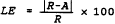 (Eq. A-4)
where,
LE = Percentage Linearity error, based upon the reference value.
R = Reference value of Low-, mid-, or high-level calibration gas introduced into the monitoring system.
A = Average of the monitoring system responses.
7.2 Calibration Error
7.2.1 Pollutant Concentration and Diluent Monitors
(Eq. A-4)
where,
LE = Percentage Linearity error, based upon the reference value.
R = Reference value of Low-, mid-, or high-level calibration gas introduced into the monitoring system.
A = Average of the monitoring system responses.
7.2 Calibration Error
7.2.1 Pollutant Concentration and Diluent Monitors
For each reference value, calculate the percentage calibration error based upon instrument span for daily calibration error tests using the following equation:
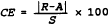 (Eq. A-5)
where,
CE = Calibration error as a percentage of the span of the instrument.
R = Reference value of zero or upscale (high-level or mid-level, as applicable) calibration gas introduced into the monitoring system.
A = Actual monitoring system response to the calibration gas.
S = Span of the instrument, as specified in section 2 of this appendix.
7.2.2 Flow Monitor Calibration Error
(Eq. A-5)
where,
CE = Calibration error as a percentage of the span of the instrument.
R = Reference value of zero or upscale (high-level or mid-level, as applicable) calibration gas introduced into the monitoring system.
A = Actual monitoring system response to the calibration gas.
S = Span of the instrument, as specified in section 2 of this appendix.
7.2.2 Flow Monitor Calibration Error
For each reference value, calculate the percentage calibration error based upon span using the following equation:
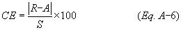 where:
CE = Calibration error as a percentage of span.
R = Low or high level reference value specified in section 2.2.2.1 of this appendix.
A = Actual flow monitor response to the reference value.
S = Flow monitor calibration span value as determined under section 2.1.4.2 of this appendix.
7.3 Relative Accuracy for SO2 and CO2 Emissions Concentration Monitors, O2 Monitors, NOX Concentration Monitoring Systems, and Flow Monitors
where:
CE = Calibration error as a percentage of span.
R = Low or high level reference value specified in section 2.2.2.1 of this appendix.
A = Actual flow monitor response to the reference value.
S = Flow monitor calibration span value as determined under section 2.1.4.2 of this appendix.
7.3 Relative Accuracy for SO2 and CO2 Emissions Concentration Monitors, O2 Monitors, NOX Concentration Monitoring Systems, and Flow Monitors
Analyze the relative accuracy test audit data from the reference method tests for SO2 and CO2 emissions concentration monitors, CO2 or O2 monitors used for heat input rate determination, NOX concentration monitoring systems used to determine NOX mass emissions under subpart H of this part, and flow monitors using the following procedures. Summarize the results on a data sheet. An example is shown in Figure 2. Calculate the mean of the monitor or monitoring system measurement values. Calculate the mean of the reference method values. Using data from the automated data acquisition and handling system, calculate the arithmetic differences between the reference method and monitor measurement data sets. Then calculate the arithmetic mean of the difference, the standard deviation, the confidence coefficient, and the monitor or monitoring system relative accuracy using the following procedures and equations.
7.3.1 Arithmetic MeanCalculate the arithmetic mean of the differences of a data set as follows:
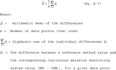 7.3.2 Standard Deviation
Calculate the standard deviation, Sd, of a data set as follows:
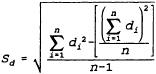 (Eq. A-8)
7.3.3 Confidence Coefficient
(Eq. A-8)
7.3.3 Confidence Coefficient
Calculate the confidence coefficient (one-tailed), cc, of a data set as follows.
 (eq. A-9)
where,
t0.025 = t value (see table 7-1).
(eq. A-9)
where,
t0.025 = t value (see table 7-1).
| n-1 | t0.025 | n-1 | t0.025 | n-1 | t0.025 |
|---|---|---|---|---|---|
| 1 | 12.706 | 12 | 2.179 | 23 | 2.069 |
| 2 | 4.303 | 13 | 2.160 | 24 | 2.064 |
| 3 | 3.182 | 14 | 2.145 | 25 | 2.060 |
| 4 | 2.776 | 15 | 2.131 | 26 | 2.056 |
| 5 | 2.571 | 16 | 2.120 | 27 | 2.052 |
| 6 | 2.447 | 17 | 2.110 | 28 | 2.048 |
| 7 | 2.365 | 18 | 2.101 | 29 | 2.045 |
| 8 | 2.306 | 19 | 2.093 | 30 | 2.042 |
| 9 | 2.262 | 20 | 2.086 | 40 | 2.021 |
| 10 | 2.228 | 21 | 2.080 | 60 | 2.000 |
| 11 | 2.201 | 22 | 2.074 | >60 | 1.960 |
Calculate the relative accuracy of a data set using the following equation.
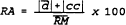 (Eq. A-10)
where,
RM = Arithmetic mean of the reference method values.
|d
| = The absolute value of the mean difference between the reference method values and the corresponding continuous emission monitoring system values.
|cc| = The absolute value of the confidence coefficient.
7.4 Relative Accuracy for NOX-diluent Continuous Emission Monitoring Systems
(Eq. A-10)
where,
RM = Arithmetic mean of the reference method values.
|d
| = The absolute value of the mean difference between the reference method values and the corresponding continuous emission monitoring system values.
|cc| = The absolute value of the confidence coefficient.
7.4 Relative Accuracy for NOX-diluent Continuous Emission Monitoring Systems
Analyze the relative accuracy test audit data from the reference method tests for NOX-diluent continuous emissions monitoring system as follows.
7.4.1 Data PreparationIf CNOx, the NOX concentration, is in ppm, multiply it by 1.194 × 10⁻⁷ (lb/dscf)/ppm to convert it to units of lb/dscf. If CNOx is in mg/dscm, multiply it by 6.24 × 10⁻⁸ (lb/dscf)/(mg/dscm) to convert it to lb/dscf. Then, use the diluent (O2 or CO2) reference method results for the run and the appropriate F or Fc factor from table 1 in appendix F of this part to convert CNOx from lb/dscf to lb/mmBtu units. Use the equations and procedure in section 3 of appendix F to this part, as appropriate.
7.4.2 NOX Emission RateFor each test run in a data set, calculate the average NOX emission rate (in lb/mmBtu), by means of the data acquisition and handling system, during the time period of the test run. Tabulate the results as shown in example Figure 4.
7.4.3 Relative AccuracyUse the equations and procedures in section 7.3 above to calculate the relative accuracy for the NOX continuous emission monitoring system. In using equation A-7, “d” is, for each run, the difference between the NOX emission rate values (in lb/mmBtu) obtained from the reference method data and the NOX continuous emission monitoring system.
7.5 Relative Accuracy for Combined SO2/Flow [Reserved] 7.6 Bias Test and Adjustment FactorTest the following relative accuracy test audit data sets for bias: SO2 pollutant concentration monitors; flow monitors; NOX concentration monitoring systems used to determine NOX mass emissions, as defined in 75.71(a)(2); and NOX-diluent CEMS using the procedures outlined in sections 7.6.1 through 7.6.5 of this appendix. For multiple-load flow RATAs, perform a bias test at each load level designated as normal under section 6.5.2.1 of this appendix.
7.6.1 Arithmetic MeanCalculate the arithmetic mean of the differences of the data set using Equation A-7 of this appendix. To calculate bias for an SO2 or NOX pollutant concentration monitor, “di” is, for each paired data point, the difference between the SO2 or NOX concentration value (in ppm) obtained from the reference method and the monitor. To calculate bias for a flow monitor, “di” is, for each paired data point, the difference between the flow rate values (in scfh) obtained from the reference method and the monitor. To calculate bias for a NOX-diluent continuous emission monitoring system, “di” is, for each paired data point, the difference between the NOX emission rate values (in lb/mmBtu) obtained from the reference method and the monitoring system.
7.6.2 Standard DeviationCalculate the standard deviation, Sd, of the data set using equation A-8.
7.6.3 Confidence CoefficientCalculate the confidence coefficient, cc, of the data set using equation A-9.
7.6.4 Bias TestIf, for the relative accuracy test audit data set being tested, the mean difference, d , is less than or equal to the absolute value of the confidence coefficient, | cc |, the monitor or monitoring system has passed the bias test. If the mean difference, d , is greater than the absolute value of the confidence coefficient, √ cc √, the monitor or monitoring system has failed to meet the bias test requirement.
7.6.5 Bias Adjustment(a) If the monitor or monitoring system fails to meet the bias test requirement, adjust the value obtained from the monitor using the following equation:
 Where:
CEMiMonitor = Data (measurement) provided by the monitor at time i.
CEMiAdjusted = Data value, adjusted for bias, at time i.
BAF = Bias adjustment factor, defined by:
Where:
CEMiMonitor = Data (measurement) provided by the monitor at time i.
CEMiAdjusted = Data value, adjusted for bias, at time i.
BAF = Bias adjustment factor, defined by:
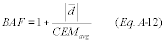 Where:
BAF = Bias adjustment factor, calculated to the nearest thousandth.
d
= Arithmetic mean of the difference obtained during the failed bias test using Equation A-7.
CEMavg = Mean of the data values provided by the monitor during the failed bias test.
Where:
BAF = Bias adjustment factor, calculated to the nearest thousandth.
d
= Arithmetic mean of the difference obtained during the failed bias test using Equation A-7.
CEMavg = Mean of the data values provided by the monitor during the failed bias test.
(b) For single-load RATAs of SO2 pollutant concentration monitors, NOX concentration monitoring systems, and NOX-diluent monitoring systems, and for the single-load flow RATAs required or allowed under section 6.5.2 of this appendix and sections 2.3.1.3(b) and 2.3.1.3(c) of appendix B to this part, the appropriate BAF is determined directly from the RATA results at normal load, using Equation A-12. Notwithstanding, when a NOX concentration CEMS or an SO2 CEMS or a NOX-diluent CEMS installed on a low-emitting affected unit (i.e., average SO2 or NOX concentration during the RATA ≤250 ppm or average NOX emission rate ≤0.200 lb/mmBtu) meets the normal 10.0 percent relative accuracy specification (as calculated using Equation A-10) or the alternate relative accuracy specification in section 3.3 of this appendix for low-emitters, but fails the bias test, the BAF may either be determined using Equation A-12, or a default BAF of 1.111 may be used.
(c) For 2-load or 3-load flow RATAs, when only one load level (low, mid or high) has been designated as normal under section 6.5.2.1 of this appendix and the bias test is passed at the normal load level, apply a BAF of 1.000 to the subsequent flow rate data. If the bias test is failed at the normal load level, use Equation A-12 to calculate the normal load BAF and then perform an additional bias test at the second most frequently-used load level, as determined under section 6.5.2.1 of this appendix. If the bias test is passed at this second load level, apply the normal load BAF to the subsequent flow rate data. If the bias test is failed at this second load level, use Equation A-12 to calculate the BAF at the second load level and apply the higher of the two BAFs (either from the normal load level or from the second load level) to the subsequent flow rate data.
(d) For 2-load or 3-load flow RATAs, when two load levels have been designated as normal under section 6.5.2.1 of this appendix and the bias test is passed at both normal load levels, apply a BAF of 1.000 to the subsequent flow rate data. If the bias test is failed at one of the normal load levels but not at the other, use Equation A-12 to calculate the BAF for the normal load level at which the bias test was failed and apply that BAF to the subsequent flow rate data. If the bias test is failed at both designated normal load levels, use Equation A-12 to calculate the BAF at each normal load level and apply the higher of the two BAFs to the subsequent flow rate data.
(e) Each time a RATA is passed and the appropriate bias adjustment factor has been determined, apply the BAF prospectively to all monitoring system data, beginning with the first clock hour following the hour in which the RATA was completed. For a 2-load flow RATA, the “hour in which the RATA was completed” refers to the hour in which the testing at both loads was completed; for a 3-load RATA, it refers to the hour in which the testing at all three loads was completed.
(f) Use the bias-adjusted values in computing substitution values in the missing data procedure, as specified in subpart D of this part, and in reporting the concentration of SO2, the flow rate, the average NOX emission rate, the unit heat input, and the calculated mass emissions of SO2 and CO2 during the quarter and calendar year, as specified in subpart G of this part. In addition, when using a NOX concentration monitoring system and a flow monitor to calculate NOX mass emissions under subpart H of this part, use bias-adjusted values for NOX concentration and flow rate in the mass emission calculations and use bias-adjusted NOX concentrations to compute the appropriate substitution values for NOX concentration in the missing data routines under subpart D of this part.
(g) For units that do not produce electrical or thermal output, the provisions of paragraphs (a) through (f) of this section apply, except that the terms, “single-load”, “2-load”, “3-load”, and “load level” shall be replaced, respectively, with the terms, “single-level”, “2-level”, “3-level”, and “operating level”.
7.7 Reference Flow-to-Load Ratio or Gross Heat Rate(a) Except as provided in section 7.8 of this appendix, the owner or operator shall determine Rref, the reference value of the ratio of flow rate to unit load, each time that a passing flow RATA is performed at a load level designated as normal in section 6.5.2.1 of this appendix. The owner or operator shall report the current value of Rref in the electronic quarterly report required under § 75.64 and shall also report the completion date of the associated RATA. If two load levels have been designated as normal under section 6.5.2.1 of this appendix, the owner or operator shall determine a separate Rref value for each of the normal load levels. The reference flow-to-load ratio shall be calculated as follows:
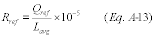 Where:
Rref = Reference value of the flow-to-load ratio, from the most recent normal-load flow RATA, scfh/megawatts, scfh/1000 lb/hr of steam, or scfh/(mmBtu/hr of steam output).
Qref = Average stack gas volumetric flow rate measured by the reference method during the normal-load RATA, scfh.
Lavg = Average unit load during the normal-load flow RATA, megawatts, 1000 lb/hr of steam, or mmBtu/hr of thermal output.
Where:
Rref = Reference value of the flow-to-load ratio, from the most recent normal-load flow RATA, scfh/megawatts, scfh/1000 lb/hr of steam, or scfh/(mmBtu/hr of steam output).
Qref = Average stack gas volumetric flow rate measured by the reference method during the normal-load RATA, scfh.
Lavg = Average unit load during the normal-load flow RATA, megawatts, 1000 lb/hr of steam, or mmBtu/hr of thermal output.
(b) In Equation A-13, for a common stack, determine Lavg by summing, for each RATA run, the operating loads of all units discharging through the common stack, and then taking the arithmetic average of the summed loads. For a unit that discharges its emissions through multiple stacks, either determine a single value of Qref for the unit or a separate value of Qref for each stack. In the former case, calculate Qref by summing, for each RATA run, the volumetric flow rates through the individual stacks and then taking the arithmetic average of the summed RATA run flow rates. In the latter case, calculate the value of Qref for each stack by taking the arithmetic average, for all RATA runs, of the flow rates through the stack. For a unit with a multiple stack discharge configuration consisting of a main stack and a bypass stack (e.g., a unit with a wet SO2 scrubber), determine Qref separately for each stack at the time of the normal load flow RATA. Round off the value of Rref to two decimal places.
(c) In addition to determining Rref or as an alternative to determining Rref, a reference value of the gross heat rate (GHR) may be determined. In order to use this option, quality-assured diluent gas (CO2 or O2) must be available for each hour of the most recent normal-load flow RATA. The reference value of the GHR shall be determined as follows:
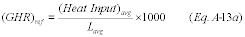 Where:
(GHR)ref = Reference value of the gross heat rate at the time of the most recent normal-load flow RATA, Btu/kwh, Btu/lb steam load, or Btu heat input/mmBtu steam output.
(Heat Input)avg = Average hourly heat input during the normal-load flow RATA, as determined using the applicable equation in appendix F to this part, mmBtu/hr. For multiple stack configurations, if the reference GHR value is determined separately for each stack, use the hourly heat input measured at each stack. If the reference GHR is determined at the unit level, sum the hourly heat inputs measured at the individual stacks.
Lavg = Average unit load during the normal-load flow RATA, megawatts, 1000 lb/hr of steam, or mmBtu/hr thermal output.
Where:
(GHR)ref = Reference value of the gross heat rate at the time of the most recent normal-load flow RATA, Btu/kwh, Btu/lb steam load, or Btu heat input/mmBtu steam output.
(Heat Input)avg = Average hourly heat input during the normal-load flow RATA, as determined using the applicable equation in appendix F to this part, mmBtu/hr. For multiple stack configurations, if the reference GHR value is determined separately for each stack, use the hourly heat input measured at each stack. If the reference GHR is determined at the unit level, sum the hourly heat inputs measured at the individual stacks.
Lavg = Average unit load during the normal-load flow RATA, megawatts, 1000 lb/hr of steam, or mmBtu/hr thermal output.
(d) In the calculation of (Heat Input)avg, use Qref, the average volumetric flow rate measured by the reference method during the RATA, and use the average diluent gas concentration measured during the flow RATA (i.e., the arithmetic average of the diluent gas concentrations for all clock hours in which a RATA run was performed).
7.8 Flow-to-Load Test Exemptions(a) For complex stack configuations (e.g., when the effluent from a unit is divided and discharges through multiple stacks in such a manner that the flow rate in the individual stacks cannot be correlated with unit load), the owner or operator may petition the Administrator under § 75.66 for an exemption from the requirements of section 7.7 of this appendix and section 2.2.5 fo appendix B to this part. The petition must include sufficient information and data to demonstrate that a flow-to-load or gross heat rate evaluation is infeasible for the complex stack configuration.
(b) Units that do not produce electrical output (in megawatts) or thermal output (in klb of steam per hour) are exempted from the flow-to-load ratio test requirements of section 7.7 of this appendix and section 2.2.5 of appendix B to this part.
| Day | Date and time | Reference value | Monitor value | Difference | Percent of reference value |
|---|---|---|---|---|---|
| Low-level: | |||||
| Mid-level: | |||||
| High-level: | |||||
| Run No. | Date and time | SO2 (ppm c) | Date and time | CO2 (Pollutant) (ppm c) | ||||
|---|---|---|---|---|---|---|---|---|
| RM a | M b | Diff | RM a | M b | Diff | |||
| 1 | ||||||||
| 2 | ||||||||
| 3 | ||||||||
| 4 | ||||||||
| 5 | ||||||||
| 6 | ||||||||
| 7 | ||||||||
| 8 | ||||||||
| 9 | ||||||||
| 10 | ||||||||
| 11 | ||||||||
| 12 | ||||||||
| Arithmetic Mean Difference (Eq. A-7). Confidence Coefficient (Eq. A-9). Relative Accuracy (Eq. A-10). | ||||||||
| a RM means “reference method data.” | ||||||||
| b M means “monitor data.” | ||||||||
| c Make sure the RM and M data are on a consistent basis, either wet or dry. |
| Run No. | Date and time | Flow rate (Low) (scf/hr)* | Date and time | Flow rate (Normal) (scf/hr)* | Date and time | Flow rate (High) (scf/hr)* | ||||||
|---|---|---|---|---|---|---|---|---|---|---|---|---|
| RM | M | Diff | RM | M | Diff | RM | M | Diff | ||||
| 1 | ||||||||||||
| 2 | ||||||||||||
| 3 | ||||||||||||
| 4 | ||||||||||||
| 5 | ||||||||||||
| 6 | ||||||||||||
| 7 | ||||||||||||
| 8 | ||||||||||||
| 9 | ||||||||||||
| 10 | ||||||||||||
| 11 | ||||||||||||
| 12 | ||||||||||||
| Arithmetic Mean Difference (Eq. A-7). Confidence Coefficient (Eq. A-9). Relative Accuracy (Eq. A-10). | ||||||||||||
| * Make sure the RM and M data are on a consistent basis, either wet or dry. |
| Run No. | Date and time | Reference method data | NOX system (lb/mmBtu) | |||
|---|---|---|---|---|---|---|
| NOX ( ) a | O2/CO2% | RM | M | Difference | ||
| 1 | ||||||
| 2 | ||||||
| 3 | ||||||
| 4 | ||||||
| 5 | ||||||
| 6 | ||||||
| 7 | ||||||
| 8 | ||||||
| 9 | ||||||
| 10 | ||||||
| 11 | ||||||
| 12 | ||||||
| Arithmetic Mean Difference (Eq. A-7). Confidence Coefficient (Eq. A-9). Relative Accuracy (Eq. A-10). | ||||||
| a Specify units: ppm, lb/dscf, mg/dscm. |
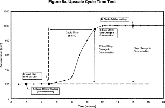
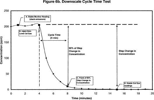
A. To determine the upscale cycle time (Figure 6a), measure the flue gas emissions until the response stabilizes. Record the stabilized value (see section 6.4 of this appendix for the stability criteria).
B. Inject a high-level calibration gas into the port leading to the calibration cell or thimble (Point B). Allow the analyzer to stabilize. Record the stabilized value.
C. Determine the step change. The step change is equal to the difference between the final stable calibration gas value (Point D) and the stabilized stack emissions value (Point A).
D. Take 95% of the step change value and add the result to the stabilized stack emissions value (Point A). Determine the time at which 95% of the step change occurred (Point C).
E. Calculate the upscale cycle time by subtracting the time at which the calibration gas was injected (Point B) from the time at which 95% of the step change occurred (Point C). In this example, upscale cycle time = (11−5) = 6 minutes.
F. To determine the downscale cycle time (Figure 6b) repeat the procedures above, except that a zero gas is injected when the flue gas emissions have stabilized, and 95% of the step change in concentration is subtracted from the stabilized stack emissions value.
G. Compare the upscale and downscale cycle time values. The longer of these two times is the cycle time for the analyzer.
Editorial Note:
For Federal Register citations affecting part 75, Appendix A, see the List of CFR Sections Affected, which appears in the Finding Aids section of the printed volume and at www.govinfo.gov.