Appendix E to Subpart UUUUU of Part 63 - Data Elements
40:16.0.1.1.1.8.214.29.47 : Appendix E
Appendix E to Subpart UUUUU of Part 63 - Data Elements
1.0 You must record the electronic data elements in this
appendix that apply to your compliance strategy under this subpart.
The applicable data elements in sections 2 through 13 of this
appendix must be reported in the quarterly compliance reports
required under 40 CFR 63.10031(g), in an XML format prescribed by
the Administrator, starting with a report that covers the first
quarter of 2024. For stack tests used to demonstrate compliance,
RATAs, PM CEMS correlations, RRAs and RCAs that are completed on
and after January 1, 2024, the applicable data elements in sections
17 through 30 of this appendix must be reported in an XML format
prescribed by the Administrator, and the information in section 31
of this appendix must be reported in as one or more PDF files.
2.0 MATS Compliance Report Root Data Elements. You must
record the following data elements and include them in each
quarterly compliance report:
2.1 Energy Information Administration's Office of Regulatory
Information Systems (ORIS) Code;
2.2 Facility Name;
2.3 Facility Registry Identifier;
2.4 Title 40 Part;
2.5 Applicable Subpart;
2.6 Calendar Year;
2.7 Calendar Quarter; and
2.8 Submission Comment (optional)
3.0 Performance Stack Test Summary. If you elect to
demonstrate compliance using periodic performance stack testing
(including 30-boiler operating day Hg LEE tests), record the
following data elements for each test:
3.1 Parameter
3.2 Test Location ID;
3.3 Test Number;
3.4 Test Begin Date, Hour, and Minute;
3.5 Test End Date, Hour, and Minute;
3.6 Timing of Test (either performed on-schedule according to 40
CFR 63.10006(f), or was late);
3.7 Averaging Plan Indicator;
3.8 Averaging Group ID (if applicable);
3.9 EPA Test Method Code;
3.10 Emission Limit, Including Units of Measure;
3.11 Average Pollutant Emission Rate;
3.12 LEE Indicator;
3.13 LEE Basis (if applicable); and
3.14 Submission Comment (optional)
4.0 Operating limit Data (PM CPMS, only):
4.1 Parameter Type;
4.2 Operating Limit; and
4.3 Units of Measure.
5.0 Performance Test Run Data. For each run of the
performance stack test, record the following data elements:
5.1 Run Number
5.2 Run Begin Date, Hour, and Minute;
5.3 Run End Date, Hour, and Minute;
5.4 Pollutant Concentration and Units of Measure;
5.5 Emission Rate;
5.6 EPA Test Method 19 Equation (if applicable);
5.7 Total Sampling Time; and
5.8 Total Sample Volume.
6.0 Conversion Parameters. For the parameters that are
used to convert the pollutant concentration to units of the
emission standard (including, as applicable, CO2 or O2
concentration, stack gas flow rate, stack gas moisture content,
F-factors, and gross output), record:
6.1 Parameter Type;
6.2 Parameter Source; and
6.3 Parameter Value, Including Units of Measure.
7.0 Quality Assurance Parameters: For key parameters that
are used to quality-assure the reference method data (including, as
applicable, filter temperature, percent isokinetic, leak check
results, percent breakthrough, percent spike recovery, and relative
deviation), record:
7.1 Parameter Type;
7.2 Parameter Value; and
7.3 Pass/Fail Status.
8.0 Averaging Group Configuration. If a particular EGU or
common stack is included in an averaging plan, record the following
data elements:
8.1 Parameter Being Averaged;
8.2 Averaging Group ID; and
8.3 Unit or Common Stack ID.
9.0 Compliance Averages. If you elect to (or are required
to) demonstrate compliance using continuous monitoring system(s) on
a 30-boiler operating day rolling average basis (or on a 30- or
90-group boiler operating day rolling WAER basis, if your monitored
EGU or common stack is in an averaging plan), you must record the
following data elements for each average emission rate (or, for
units in an averaging plan, for each WAER):
9.1 Unit or Common Stack ID;
9.2 Averaging Group ID (if applicable);
9.3 Parameter Being Averaged;
9.4 Date;
9.5 Average Type;
9.6 Units of Measure; and
9.7 Average Value.
9.8 Comment Field.
10.0 Unit Information. You must record the following data
elements for each EGU:
10.1 Unit ID;
10.2 Date of Last Tune-up; and
10.3 Emergency Bypass Information. If your coal-fired EGU, solid
oil-derived fuel-fired EGU, or IGCC is equipped with a main stack
and a bypass stack (or bypass duct) configuration, and has
qualified to use the LEE compliance option, you must report the
following emergency bypass information annually, in the compliance
report for the fourth calendar quarter of the year:
10.3.1 The number of emergency bypass hours for the year, as a
percentage of the EGU's annual operating hours;
10.3.2 A description of each emergency bypass event during the
year, including the cause and corrective actions taken;
10.3.3 An explanation of how clean fuels were burned to the
maximum extent possible during each emergency bypass event;
10.3.4 An estimate of the emissions released during each
emergency bypass event. You must also show whether LEE status has
been retained or lost, based on the emissions estimate and the
results of the previous LEE retest; and
10.3.5 If there were no emergency bypass events during the year,
a statement to that effect.
11.0 Fuel Usage Information. If subject to an emissions
limit, record the following monthly fuel usage information:
11.1 Calendar Month;
11.2 Each Type of Fuel Used During the Calendar Month in the
Quarter;
11.3 Quantity of Each Type of Fuel Combusted in Each Calendar
Month in the Quarter, with Units of Measure;
11.4 New Fuel Type Indicator (if applicable); and
11.5 Date of Performance Test Using the New Fuel (if
applicable.
12.0 Malfunction Information (if applicable): If there
was a malfunction of the process equipment or control equipment
during the reporting period that caused (or may have caused) an
exceedance of an emissions or operating limit, record:
12.1 Event Begin Date and Hour (if known);
12.2 Event End Date and Hour;
12.3 Malfunction Description; and
12.4 Corrective Action.
13.0 Deviations and Monitoring Downtime. If there were
any deviations or monitoring downtime during the reporting period,
record:
13.1 Unit, Common Stack, or Averaging Group ID;
13.2 The nature of the deviation, as either:
13.2.1 Emission limit exceeded;
13.2.2 Operating limit exceeded;
13.2.3 Work practice standard not met;
13.2.4 Testing requirement not met;
13.2.5 Monitoring requirement not met;
13.2.6 Monitoring downtime incurred; or
13.2.7 Other requirement not met.
13.3 A description of the deviation, or monitoring downtime, as
follows:
13.3.1 For a performance stack test or a 30- (or 90-) boiler
operating day rolling average that exceeds an emissions or
operating limit, record the parameter (e.g., HCl, Hg, PM),
the limit that was exceeded, and either the date of the
non-complying performance test or the beginning and ending dates of
the non-complying rolling average;
13.3.2 If an unmonitored bypass stack was used during the
reporting period, record the total number of hours of bypass stack
usage;
13.3.3 For periods where valid monitoring data are not reported
during the reporting period, record the monitored parameter, the
total source operating time (hours), and the total number of hours
of monitoring deviation or downtime and other information, as
indicated, for:
13.3.3.1 Monitoring system malfunctions/repairs (deviation and
downtime);
13.3.3.2 Out-of-control periods/repairs (deviation and
downtime);
13.3.3.3 Non-monitoring equipment malfunctions (downtime);
13.3.3.4 QA/QC activities (excluding zero and span checks)
(downtime);
13.3.3.5 Routine maintenance (downtime);
13.3.3.6 Other known causes (downtime); and
13.3.3.7 Unknown causes (downtime).
13.3.4 If a performance stack test was due within the quarter
but was not done, record the parameter (e.g., HCl, PM), the
test deadline, and a statement that the test was not done as
required;
13.3.5 For a late performance stack test conducted during the
quarter, record the parameter, the test deadline, and the number of
days that elapsed between the test deadline and the test completion
date.
13.4 Record any corrective actions taken in response to the
deviation.
13.5 If there were no deviations and/or no monitoring downtime
during the quarter, record a statement to that effect.
14.0 Reference Method Data Elements. For each of the
following tests that is completed on and after January 1, 2024, you
must record and report the applicable electronic data elements in
sections 17 through 29 of this appendix, pertaining to the
reference method(s) used for the test (see section 16 of this
appendix).
14.1 Each quarterly, annual, or triennial stack test used to
demonstrate compliance (including 30- (or 90-) boiler operating day
Hg LEE tests and PM tests used to set operating limits for PM
CPMS);
14.2 Each RATA of your Hg, HCl, HF, or SO2 CEMS or each RATA of
your Hg sorbent trap monitoring system; and
14.3 Each correlation test, RRA and each RCA of your PM
CEMS.
15.0 You must report the applicable data elements for each test
described in section 14 of this appendix in an XML format
prescribed by the Administrator.
15.1 For each stack test completed during a particular calendar
quarter and contained in the quarterly compliance report, you must
submit along with the quarterly compliance report, the data
elements in sections 17 and 18 of this appendix (which are common
to all tests) and the applicable data elements in sections 19
through 31 of this appendix associated with the reference method(s)
used.
15.2 For each RATA, PM CEMS correlation, RRA, or RCA, when you
use the ECMPS Client Tool to report the test results as required
under appendix A, B, or C to this subpart or, for SO2 RATAs under
part 75 of this chapter, you must submit along with the test
results, the data elements in sections 17 and 18 of this appendix
and, for each test run, the data elements in sections 19 through 30
of this appendix that are associated with the reference method(s)
used.
15.3 For each stack test, RATA, PM CEMS correlation, RRA, and
RCA, you must also provide the information described in section 31
of this appendix as a PDF file, either along with the quarterly
compliance report (for stack tests) or together with the test
results reported under appendix A, B, or C to this subpart or part
75 of this chapter (for RATAs, RRAs, RCAs, or PM CEMS
correlations).
16.0 Applicable Reference Methods. One or more of the
following EPA reference methods is needed for the tests described
in sections 14.1 through 14.3 of this appendix: Method 1, 2, 3A, 4,
5, 5D, 6C, 26, 26A, 29, and/or 30B.
16.1 Application of EPA test Methods 1 and 2. If you use
periodic stack testing to comply with an output-based
emissions limit, you must determine the stack gas flow rate during
each performance test run in which EPA test Method 5, 5D, 26, 26A,
29, or 30B is used, in order to convert the measured pollutant
concentration to units of the standard. For EPA test Methods 5, 5D,
26A and 29, which require isokinetic sampling, the delta-P readings
made with the pitot tube and manometer at the EPA test Method 1
traverse points, taken together with measurements of stack gas
temperature, pressure, diluent gas concentration (from a separate
EPA test Method 3A or 3B test) and moisture, provide the necessary
data for the EPA test Method 2 flow rate calculations. Note that
even if you elect to comply with a heat input-based
standard, when EPA test Method 5, 5D, 26A, or 29 is used, you must
still use EPA test Method 2 to determine the average stack gas
velocity (vs), which is needed for the percent isokinetic
calculation. The EPA test Methods 26 and 30B do not require
isokinetic sampling; therefore, when either of these methods is
used, if the stack gas flow rate is needed to comply with the
applicable output-based emissions limit, you must make a
separate EPA test Method 2 determination during each test run.
16.2 Application of EPA test Method 3A. If you elect to perform
periodic stack testing to comply with a heat input-based
emissions limit, a separate measurement of the diluent gas (CO2 or
O2) concentration is required for each test run in which EPA test
Method 5, 5D, 26, 26A, 29, or 30B is used, in order to convert the
measured pollutant concentration to units of the standard. The EPA
test Method 3A is the preferred CO2 or O2 test method, although EPA
test Method 3B may be used instead. Diluent gas measurements are
also needed for stack gas molecular weight determinations when
using EPA test Method 2.
16.3 Application of EPA test Method 4. For performance stack
tests, depending on which equation is used to convert pollutant
concentration to units of the standard, measurement of the stack
gas moisture content, using EPA test Method 4, may also be required
for each test run. The EPA test Method 4 moisture data are also
needed for the EPA test Method 2 calculations (to determine the
molecular weight of the gas) and for the RATA of an Hg CEMS that
measures on a wet basis, when EPA test Method 30B is used. Other
applications that require EPA test Method 4 moisture determinations
include: RATAs of an SO2 monitor, when the reference method and
CEMS data are measured on a different moisture basis (wet or dry);
conversion of wet-basis pollutant concentrations to the units of a
heat input-based emissions limit when certain EPA test
Method 19 equations are used (e.g., Eq. 19-3, 19-4, or
19-8); and stack gas molecular weight determinations. When EPA test
Method 5, 5D, 26A, or 29 is used for the performance test, the EPA
test Method 4 moisture determination may be made by using the water
collected in the impingers together with data from the dry gas
meter; alternatively, a separate EPA test Method 4 determination
may be made. However, when EPA test Method 26 or 30B is used, EPA
test Method 4 must be performed separately.
16.4 Applications of EPA test Methods 5 and 5D. The EPA test
Method 5 (or, if applicable 5D) must be used for the following
applications: To demonstrate compliance with a filterable PM
emissions limit; for PM tests used to set operating limits for PM
CPMS; and for the initial correlations, RRAs and RCAs of a PM
CEMS.
16.5 Applications of EPA test Method 6C. If you elect to monitor
SO2 emissions from your coal-fired EGU as a surrogate for HCl, the
SO2 CEMS must be installed, certified, operated, and maintained
according to 40 CFR part 75. Part 75 allows the use of EPA test
Methods 6, 6A, 6B, and 6C for the required RATAs of the SO2
monitor. However, in practice, only instrumental EPA test Method 6C
is used.
16.6 Applications of EPA test Methods 26 and 26A. The EPA test
Method 26A may be used for quarterly HCl or HF stack testing, or
for the RATA of an HCl or HF CEMS. The EPA test Method 26 may be
used for quarterly HCl or HF stack testing; however, for the RATAs
of an HCl monitor that is following PS 18 and Procedure 6 in
appendices B and F to part 60 of this chapter, EPA test Method 26
may only be used if approved upon request.
16.7 Applications of EPA test Method 29. The EPA test Method 29
may be used for periodic performance stack tests to determine
compliance with individual or total HAP metals emissions limits.
For coal-fired EGUs, the total HAP emissions limits exclude Hg.
16.8 Applications of EPA test Method 30B. The EPA test Method
30B is used for 30- (or 90-) boiler operating day Hg LEE tests and
RATAs of Hg CEMS and sorbent trap monitoring systems, and it may be
used for quarterly Hg stack testing (oil-fired EGUs, only).
17.0 Facility and Test Company Information. In accordance
with 40 CFR 63.7(e)(3), a test is defined as three or more runs of
one or more EPA Reference Method(s) conducted to measure the amount
of a specific regulated pollutant, pollutants, or surrogates being
emitted from a particular EGU (or group of EGUs that share a common
stack), and to satisfy requirements of this subpart. On or after
January 1, 2024, you must report the data elements in sections 17
and 18, each time that you complete a required performance stack
test, RATA, PM CEMS correlation, RRA, or RCA at the affected
EGU(s), using EPA test Method 5, 5B, 5D, 6C, 26, 26A, 29, or 30B.
You must also report the applicable data elements in sections 19
through 25 of this appendix for each test. If any separate,
corresponding EPA test Method 2, 3A, or 4 test is conducted in
order to convert a pollutant concentration to the units of the
applicable emission standard given in Table 1 or Table 2 of this
subpart or to convert pollutant concentration from wet to dry basis
(or vice-versa), you must also report the applicable data elements
in sections 26 through 31 of this appendix.
The applicable data elements in sections 17 through 31 of this
appendix must be submitted separately, in XML format, along with
the quarterly Compliance Report (for stack tests) or along with the
electronic test results submitted to the ECMPS Client Tool (for CMS
performance evaluations). The Electronic Reporting Tool (ERT) or an
equivalent schema can be utilized to create this XML file.
Note: Ideally, for all of the tests completed at a given
facility in a particular calendar quarter, the applicable data
elements in sections 17 through 31 of this appendix should be
submitted together in one XML file. However, as shown in Table 8 to
this subpart, the timelines for submitting stack test results and
CMS performance evaluations are not identical. Therefore, for
calendar quarters in which both types of tests are completed, it
may not be possible to submit the applicable data elements for all
of those tests in a single XML file; separate submittals may be
necessary to meet the applicable reporting deadlines.
17.1 Part;
17.2 Subpart;
17.3 ORIS Code;
17.4 Facility Name;
17.5 Facility Address;
17.6 Facility City;
17.7 Facility County;
17.8 Facility State;
17.9 Facility Zip Code;
17.10 Facility Point of Contact;
17.11 Facility Contact Phone Number;
17.12 Facility Contact Email;
17.13 EPA Facility Registration System Number;
17.14 Source Classification Code;
17.15 State Facility ID;
17.16 Project Number;
17.17 Name of Test Company;
17.18 Test Company Address;
17.19 Test Company City;
17.20 Test Company State;
17.21 Test Company Zip Code;
17.22 Test Company Point of Contact;
17.23 Test Company Contact Phone Number;
17.24 Test Company Contact Email; and
17.25 Test Comment (optional, PM CPMS operating limits, if
applicable).
18.0 Source Information Data Elements. You must report
the following data elements, as applicable, for each source for
which at least one test is included in the XML file:
18.1 Source ID (sampling location);
18.2 Stack (duct) Diameter (circular stack) (in.);
18.3 Equivalent Diameter (rectangular duct or stack) (in.);
18.4 Area of Stack;
18.5 Control Device Code; and
18.6 Control Device Description.
19.0 Run-Level and Lab Data Elements for EPA test Methods 5,
5B, 5D, 26A, and 29. You must report the appropriate Source ID
(i.e., Data Element 18.1) and the following data elements,
as applicable, for each run of each performance stack test, PM CEMS
correlation test, RATA, RRA, or RCA conducted using isokinetic EPA
test Method 5, 5B, 5D, or 26A. If your EGU is oil-fired and you use
EPA test Method 26A to conduct stack tests for both HCl and HF, you
must report these data elements separately for each pollutant. When
you use EPA test Method 29 to measure the individual HAP metals,
total filterable HAP metals and total HAP metals, report only the
run-level data elements (19.1, 19.3 through 19.30, and 19.38
through 19.41), and the point-level and lab data elements in
sections 20 and 21 of this appendix:
19.1 Test Number;
19.2 Pollutant Name;
19.3 EPA Test Method;
19.4 Run Number;
19.5 Corresponding Reference Method(s), if applicable;
19.6 Corresponding Reference Method(s) Run Number, if
applicable;
19.7 Number of Traverse Points;
19.8 Run Begin Date;
19.9 Run Start Time (clock time start);
19.10 Run End Date;
19.11 Run End Time (clock time end);
19.12 Barometric Pressure;
19.13 Static Pressure;
19.14 Cumulative Elapsed Sampling Time;
19.15 Percent O2;
19.16 Percent CO2;
19.17 Pitot Tube ID;
19.18 Pitot Tube Calibration Coefficient;
19.19 Nozzle Calibration Diameter;
19.20 F-Factor (Fd, Fw, or Fc);
19.21 Calibration Coefficient of Dry Gas Meter (Y);
19.22 Total Volume of Liquid Collected in Impingers and Silica
Gel;
19.23 Percent Moisture - Actual;
19.24 Dry Molecular Weight of Stack Gas;
19.25 Wet Molecular Weight of Stack Gas;
19.26 Initial Reading of Dry Gas Meter Volume (dcf);
19.27 Final Reading of Dry Gas Meter Volume (dcf);
19.28 Stack Gas Velocity - fps;
19.29 Stack Gas Flow Rate - dscfm;
19.30 Type of Fuel;
19.31 Pollutant Mass Collected (value);
19.32 Pollutant Mass Unit of Measure;
19.33 Detection Limit Flag;
19.34 Pollutant Concentration;
19.35 Pollutant Concentration Unit of Measure;
19.36 Pollutant Emission Rate;
19.37 Pollutant Emission Rate Units of Measure (in units of the
standard);
19.38 Compliance Limit Basis (heat input or electrical
output);
19.39 Heat Input or Electrical Output Unit of Measure;
19.40 Process Parameter (value);
19.41 Process Parameter Unit of Measure;
19.42 Converted Concentration for PM CEMS only; and
19.43 Converted Concentration Units (units of correlation for PM
CEMS).
20.0 Point-Level Data Elements for EPA test Methods 5, 5B,
5D, 26A, & 29. To link the point-level data with the run data
in the xml schema, you must report the Source ID (i.e., Data
Element 18.1), EPA Test Method (Data Element 19.3), Run Number
(Data Element 19.4), and Run Begin Date (Data Element 19.8) with
the following point-level data elements for each run of each
performance stack test, PM CEMS correlation test, RATA, RRA, or RCA
conducted using isokinetic EPA test Method 5, 5B, 5D, 26A, or 29.
Note that these data elements are required for all EPA test Method
29 applications, whether the method is being used to measure the
total or individual HAP metals concentrations:
20.1 Traverse Point ID;
20.2 Stack Temperature;
20.3 Differential Pressure Reading (ΔP);
20.4 Orifice Pressure Reading (ΔH);
20.5 Dry Gas Meter Inlet Temperature;
20.6 Dry Gas Meter Outlet Temperature; and
20.7 Filter Temperature.
21.0 Laboratory Results for EPA test Methods 29 Total or
Individual Multiple HAP Metals. If you use EPA test Method 29
and elect to comply with the total or individual HAP metals
standards, you must report run-level data elements 19.1 through
19.34 in Section 19, and the point-level data elements in Section
20. To link the laboratory data with the run data in the xml
schema, you must report the Source ID (i.e., Data Element
18.1), EPA Test Method (Data Element 19.3), Run Number (Data
Element 19.4), and Run Begin Date (Data Element 19.8) with the
results of the laboratory analyses. Regardless of whether you elect
to comply with the total HAP metals standard or the individual HAP
metals standard, you must report the front half catch, the back
half catch, and the sum of the front and back half catches
collected with EPA test Method 29 for each individual HAP metal and
for the total HAP metals. The list of individual HAP metals is
Antimony, Arsenic, Beryllium, Cadmium, Chromium, Cobalt, Lead,
Manganese, Nickel, Selenium, and Mercury (if applicable). You must
also calculate and report the pollutant emission rates(s) in
relation to the standard(s) with which you have elected to comply
and the units specified in Table 5 as follows:
21.1 Each Individual HAP metal total mass collected:
21.1.1 Pollutant Name;
21.1.2 Pollutant Mass Collected;
21.1.3 Pollutant Mass Units of Measure; and
21.1.4 Detection Limit Flag.
21.2 Each Individual HAP metal Front Half:
21.2.1 Pollutant Name;
21.2.2 Pollutant Mass Collected;
21.2.3 Pollutant Mass Units of Measure; and
21.2.4 Detection Limit Flag.
21.3 Each Individual HAP metal Back Half:
21.3.1 Pollutant Name;
21.3.2 Pollutant Mass Collected;
21.3.3 Pollutant Mass Units of Measure; and
21.3.4 Detection Limit Flag.
21.4 Each Individual HAP metal concentration:
21.4.1 Pollutant Name;
21.4.2 Pollutant Concentration; and
21.4.3 Pollutant Concentration Units of Measure.
21.5 Each Individual HAP metal emission rate in units of the
standard:
21.5.1 Pollutant Name;
21.5.2 Pollutant Emission Rate; and
21.5.3 Pollutant Emission Rate Units of Measure.
21.6 Each Individual HAP metal emission rate in units of
lbs/MMBTU or lbs/MW (per Table 5):
21.6.1 Pollutant Name;
21.6.2 Pollutant Emission Rate; and
21.6.3 Pollutant Emission Rate Units of Measure.
21.7 Total Filterable HAP metals mass collected:
21.7.1 Pollutant Name;
21.7.2 Pollutant Mass Collected;
21.7.3 Pollutant Mass Units of Measure; and
21.7.4 Detection Limit Flag.
21.8 Total Filterable HAP metals concentration:
21.8.1 Pollutant Name;
21.8.2 Pollutant Concentration; and
21.8.3 Pollutant Concentration Units of Measure.
21.9 Total Filterable HAP metals in units of lbs/MMBtu or lbs/MW
(per Table 5):
21.9.1 Pollutant Name;
21.9.2 Pollutant Emission Rate; and
21.9.3 Pollutant Emission Rate Units of Measure.
21.10 Total HAP metals mass collected:
21.10.1 Pollutant Name;
21.10.2 Pollutant Mass Collected;
21.10.3 Pollutant Mass Units of Measure; and
21.10.4 Detection Limit Flag.
21.11 Total HAP metals concentration
21.11.1 Pollutant Name;
21.11.2 Pollutant Concentration; and
21.11.3 Pollutant Concentration Units of Measure.
21.12 Total HAP metals Emission Rate in Units of the
Standard:
21.12.1 Pollutant Name;
21.12.2 Pollutant Emission Rate; and
21.12.3 Pollutant Emission Rate Units of Measure.
21.13 Total HAP metals Emission Rate in lbs/MMBtu or lbs/MW (per
Table 5):
21.13.1 Pollutant Name;
21.13.2 Pollutant Emission Rate; and
21.13.3 Pollutant Emission Rate Units of Measure.
22.0 Run-Level and Lab Data Elements for EPA test Method
26. If you use EPA test Method 26, you must report the Source
ID (i.e., Data Element 18.1) and the following run-level
data elements for each test run. If your EGU is oil-fired and you
use EPA test Method 26 to conduct stack tests for both HCl and HF,
you must report these data elements separately for each
pollutant:
22.1 Test Number;
22.2 Pollutant Name;
22.3 EPA Test Method;
22.4 Run Number;
22.5 Corresponding Reference Method(s), if applicable;
22.6 Corresponding Reference Method(s) Run Number, if
applicable;
22.7 Number of Traverse Points;
22.8 Run Begin Date;
22.9 Run Start Time (clock start time);
22.10 Run End Date;
22.11 Run End Time (clock end time);
22.12 Barometric Pressure;
22.13 Cumulative Elapsed Sampling Time;
22.14 Calibration Coefficient of Dry Gas Meter (Y);
22.15 Initial Reading of Dry Gas Meter Volume (dcf);
22.16 Final Reading of Dry Gas Meter Volume (dcf);
22.17 Percent O2;
22.18 Percent CO2;
22.19 Type of Fuel;
22.20 F-Factor (Fd, Fw, or Fc);
22.21 Pollutant Mass Collected (value);
22.22 Pollutant Mass Units of Measure;
22.23 Detection Limit Flag;
22.24 Pollutant Concentration;
22.25 Pollutant Concentration Unit of Measure;
22.26 Compliance Limit Basis (heat input or electrical
output);
22.27 Heat Input or Electrical Output Unit of Measure;
22.28 Process Parameter (value);
22.29 Process Parameter Unit of Measure;
22.30 Pollutant Emission Rate; and
22.31 Pollutant Emission Rate Units of Measure (in the units of
the standard).
23.0 Point-Level Data Elements for EPA test Method 26. To
link the point-level data in this section with the run-level data
in the XML schema, you must report the Source ID (i.e., Data
Element 18.1), EPA Test Method (Data Element 22.3), Run Number
(Data Element 22.4), and Run Begin Date (Data Element 22.8) from
section 22 and the following point-level data elements for each run
of each EPA test Method 26 test:
23.1 Traverse Point ID;
23.2 Filter Temperature; and
23.3 Dry Gas Meter Temperature.
24.0 Run-Level Data for EPA test Method 30B. You must
report Source ID (i.e. Data Element 18.1) and the following
run-level data elements for each EPA test Method 30B test run:
24.1 Test Number;
24.2 Pollutant Name;
24.3 EPA Test Method;
24.4 Run Number;
24.5 Corresponding Reference Method(s), if applicable;
24.6 Corresponding Reference Method(s) Run Number, if
applicable;
24.7 Number of Traverse Points;
24.8 Run Begin Date;
24.9 Run Start Time (clock time start);
24.10 Run End Date;
24.11 Run End Time (clock time end);
24.12 Barometric Pressure;
24.13 Percent O2;
24.14 Percent CO2;
24.15 Cumulative Elapsed Sampling Time;
24.16 Calibration Coefficient of Dry Gas Meter Box A (Y);
24.17 Initial Reading of Dry Gas Meter Volume (A);
24.18 Final Reading of Dry Gas Meter Volume (A);
24.19 Calibration Coefficient of Dry Gas Meter Box B (Y);
24.20 Initial Reading of Dry Gas Meter Volume (B);
24.21 Final Reading of Dry Gas Meter Volume (B);
24.22 Gas Sample Volume Units of Measure;
24.23 Post-Run Leak Rate (A);
24.24 Post-Run Leak Check Vacuum (A);
24.25 Post-Run Leak Rate (B);
24.26 Post-Run Leak Check Vacuum (B);
24.27 Sorbent Trap ID (A);
24.28 Pollutant Mass Collected, Section 1 (A);
24.29 Pollutant Mass Collected, Section 2 (A);
24.30 Mass of Spike on Sorbent Trap A;
24.31 Total Pollutant Mass Trap A;
24.32 Sorbent Trap ID (B);
24.33 Pollutant Mass Collected, Section 1 (B);
24.34 Pollutant Mass Collected, Section 2 (B);
24.35 Mass of Spike on Sorbent Trap B;
24.36 Total Pollutant Mass Trap B;
24.37 Pollutant Mass Units of Measure;
24.38 Pollutant Average Concentration;
24.39 Pollutant Concentration Units of Measure;
24.40 Method Detection Limit;
24.41 Percent Spike Recovery;
24.42 Type of Fuel;
24.43 F-Factor (Fd, Fw, or Fc);
24.44 Compliance Limit Basis (heat input or electrical
output);
24.45 Heat Input or Electrical Output Unit of Measure;
24.46 Process Parameter (value);
24.47 Process Parameter Unit of Measure;
24.48 Pollutant Emission Rate; and
24.49 Pollutant Emission Rate Unit of Measure (in the units of
the standard).
25.0 Point-Level Data Elements for EPA test Method 30B.
You must report the Source ID (i.e., Data Element 18.1), EPA
Test Method (Data Element 24.3), Run Number (Data Element 24.4),
and Run Begin Date (Data Element 24.8) and the following
point-level data elements for each run of each EPA test Method 30B
test:
25.1 Traverse Point ID;
25.2 Dry Gas Meter Temperature (A);
25.3 Sample Flow Rate (A) (L/min);
25.4 Dry Gas Meter Temperature (B); and
25.5 Sample Flow Rate (B) (L/min).
26.0 Pre-Run Data Elements for EPA test Methods 3A and
6C. You must report the Source ID (i.e., Data Element
18.1) and the following pre-run data elements for each SO2 RATA
using instrumental EPA test Method 6C, and for each instrumental
EPA test Method 3A O2 or CO2 test that is performed to convert a
pollutant concentration to the units of measure of the applicable
emission unit of standard in Table 1 or 2 of this subpart:
26.1 Test Number;
26.2 EPA Test Method;
26.3 Calibration Gas Cylinder Analyte;
26.4 Cylinder Gas Units of Measure;
26.5 Date of Calibration;
26.6 Calibration Low-Level Gas Cylinder ID;
26.7 Calibration Low-Level Gas Concentration;
26.8 Calibration Low-Level Cylinder Expiration Date;
26.9 Calibration Mid-Level Gas Cylinder ID;
26.10 Calibration Mid-Level Gas Concentration;
26.11 Calibration Mid-Level Cylinder Expiration Date;
26.12 Calibration High-Level Gas Cylinder ID;
26.13 Calibration Span (High-Level) Gas Concentration;
26.14 Calibration High-Level Cylinder Expiration Date;
26.15 Low-Level Gas Response;
26.16 Low-Level Calibration Error;
26.17 Low-Level Alternate Performance Specification (APS)
Flag;
26.18 Mid-Level Gas Response;
26.19 Mid-Level Calibration Error;
26.20 Mid-Level APS Flag;
26.21 High-Level Gas Response;
26.22 High-Level Calibration Error; and
26.23 High-Level APS Flag.
27.0 Run-Level Data Elements for EPA test Methods 3A and
6C. You must report the Source ID (i.e., Data Element
18.1) and following run-level data elements for each run of each
SO2 RATA using instrumental EPA test Method 6C, and for each run of
each corresponding instrumental EPA test Method 3A test that is
performed to convert a pollutant concentration to the applicable
emission unit of standard in Table 1 or 2 of this subpart:
27.1 Test Number;
27.2 Pollutant or Analyte Name;
27.3 EPA Test Method;
27.4 Run Number;
27.5 Corresponding Reference Method(s), if applicable;
27.6 Corresponding Reference Method(s) Run Number(s), if
applicable;
27.7 Number of Traverse Points;
27.8 Run Begin Date;
27.9 Run Start Time (clock time start);
27.10 Run End Date;
27.11 Run End Time (clock time end);
27.12 Cumulative Elapsed Sampling Time;
27.13 Upscale (mid or high) Gas Level;
27.14 Pre-Run Low-Level Response;
27.15 Pre-Run Low-Level System Bias;
27.16 Pre-Run Low-Level Bias APS Flag;
27.17 Pre-Run Upscale (mid or high) Response;
27.18 Pre-Run Upscale (mid or high) System Bias;
27.19 Pre-Run Upscale (mid or high) Bias APS Flag;
27.20 Post-Run Low-Level Response;
27.21 Post-Run Low-Level System Bias;
27.22 Post-Run Low-Level Bias APS Flag;
27.23 Post-Run Low-Level Drift;
27.24 Post-Run Low-Level Drift APS Flag;
27.25 Post-Run Upscale (mid or high) Response;
27.26 Post-Run Upscale (mid or high) System Bias;
27.27 Post-Run Upscale (mid or high) System Bias APS Flag;
27.28 Post-Run Upscale (mid or high) Drift;
27.29 Post-Run Upscale (mid or high) Drift APS Flag;
27.30 Unadjusted Raw Emissions Average Concentration;
27.31 Calculated Average Concentration, Adjusted for Bias
(Cgas);
27.32 Concentration Units of Measure (Dry or wet);
27.33 Type of Fuel;
27.34 Process Parameter (value); and
27.35 Process Parameter Units of Measure.
28.0 Run-Level Data Elements for EPA test Method 2. When
you make a separate determination of the stack gas flow rate using
EPA test Method 2 separately, corresponding to a pollutant
reference method test, i.e., when data from the pollutant
reference method cannot determine the stack gas flow rate, you must
report the Source ID (i.e., Data Element 18.1) and following
run-level data elements for each EPA test Method 2 test run:
28.1 Test Number;
28.2 EPA Test Method;
28.3 Run Number;
28.4 Number of Traverse Points;
28.5 Run Begin Date;
28.6 Run Start Time (clock time start);
28.7 Run End Date;
28.8 Run End Time (clock time end);
28.9 Pitot Tube ID;
28.10 Pitot Tube Calibration Coefficient;
28.11 Barometric Pressure;
28.12 Static Pressure;
28.13 Percent O2;
28.14 Percent CO2;
28.15 Percent Moisture - actual;
28.16 Dry Molecular Weight of Stack Gas;
28.17 Wet Molecular Weight of Stack Gas;
28.18 Stack Gas Velocity - fps; and
28.19 Stack Gas Flow Rate - dscfm.
29.0 Point-Level Data Elements for EPA test Method 2. For
each run of each separate EPA test Method 2 test, you must report
the Source ID (i.e., Data Element 18.1), EPA Test Method
(Data Element 28.2), Run Number (Data Element 28.3), and Run Begin
Date (Data Element 28.5) and the following point-level data
elements:
29.1 Traverse Point ID;
29.2 Stack Temperature; and
29.3 Differential Pressure Reading (ΔP).
30.0 Run-Level Data Elements for EPA test Method 4. When
you make a separate EPA test Method 4 determination of the stack
gas moisture content corresponding to a pollutant reference method
test, i.e., when data from the pollutant reference method
cannot determine the moisture content, you must report the Source
ID (i.e., Data Element 18.1) and the following run-level
data elements for each EPA test Method 4 test run:
30.1 Test Number;
30.2 EPA Test Method;
30.3 Run Number;
30.4 Number of Traverse Points;
30.5 Run Begin Date;
30.6 Run Start Time (clock time start);
30.7 Run End Date;
30.8 Run End Time (clock time end);
30.9 Barometric Pressure;
30.10 Calibration Coefficient of Dry Gas Meter (Y);
30.11 Volume of Water Collected in Impingers and Silica Gel;
30.12 Percent Moisture-actual;
30.13 Initial Reading of Dry Gas Meter Volume (dcf);
30.14 Final Reading of Dry Gas Meter Volume (dcf); and
30.15 Dry Gas Meter Temperature (average).
31.0 Other Information for Each Test or Test Series. You
must provide each test included in the XML data file described in
this appendix with supporting documentation, in a PDF file
submitted concurrently with the XML file, such that all the data
required to be reported by 40 CFR 63.7(g) are provided. That
supporting data include but are not limited to diagrams showing the
location of the test site and the sampling points, laboratory
report(s) including analytical calibrations, calibrations of source
sampling equipment, calibration gas cylinder certificates, raw
instrumental data, field data sheets, quality assurance data
(e.g. field recovery spikes) and any required audit results
and stack testers' credentials (if applicable). The applicable data
elements in 40 CFR 63.10031(f)(6)(i) through (xii) of this section
must be entered into ECMPS with each PDF submittal; the test
number(s) (see 40 CFR 63.10031(f)(6)(xi)) must be included. The
test number(s) must match the test number(s) in sections 19 through
31 of this appendix (as applicable).
[85 FR 55775, Sept. 9, 2020]
Appendix E to Part 63 - Monitoring Procedure for Nonthoroughly Mixed Open Biological Treatment Systems at Kraft Pulp Mills Under Unsafe Sampling Conditions
40:16.0.1.1.1.46.325.36.126 : Appendix E
Appendix E to Part 63 - Monitoring Procedure for Nonthoroughly
Mixed Open Biological Treatment Systems at Kraft Pulp Mills Under
Unsafe Sampling Conditions I. Purpose
This procedure is required to be performed in subpart S of this
part, entitled National Emission Standards for Hazardous Air
Pollutants from the Pulp and Paper Industry. Subpart S requires
this procedure in § 63.453(p)(3) to be followed during unsafe
sampling conditions when it is not practicable to obtain
representative samples of hazardous air pollutants (HAP)
concentrations from an open biological treatment unit. It is
assumed that inlet and outlet HAP concentrations from the open
biological treatment unit may be obtained during the unsafe
sampling conditions. The purpose of this procedure is to estimate
the concentration of HAP within the open biological treatment unit
based on information obtained at inlet and outlet sampling
locations in units that are not thoroughly mixed and, therefore,
have different concentrations of HAP at different locations within
the unit.
II. Definitions
Biological treatment unit = wastewater treatment unit designed
and operated to promote the growth of bacteria to destroy organic
materials in wastewater.
fbio = The fraction of organic compounds in the wastewater
biodegraded in a biological treatment unit. Fe = The fraction of
applicable organic compounds emitted from the wastewater to the
atmosphere. K1 = First-order biodegradation rate constant, L/g
mixed liquor volatile suspended solids (MLVSS)-hr KL = Liquid-phase
mass transfer coefficient, m/s Ks = Monod biorate constant at half
the maximum rate, g/m 3 III. Test Procedure for Determination of
fbio for Nonthoroughly Mixed Open Biological Treatment Units Under
Unsafe Sampling Conditions
This test procedure is used under unsafe sampling conditions
that do not permit practicable sampling of open biological
treatment units within the unit itself, but rather relies on
sampling at the inlet and outlet locations of the unit. This
procedure may be used only under unsafe sampling conditions to
estimate fbio. Once the unsafe conditions have passed, then the
formal compliance demonstration procedures of fbio based upon
measurements within the open biological treatment unit must be
completed.
A. Overview of Estimation Procedure
The steps in the estimation procedure include data collection,
the estimation of concentrations within the unit, and the use of
Form 1 to estimate fbio. The data collection procedure consists of
two separate components. The first data collection component
demonstrates that the open biological treatment unit can be
represented by Monod kinetics and characterizes the effectiveness
of the open biological treatment unit as part of the initial
performance test, and the second data collection component is used
when there are unsafe sampling conditions. These two data
collection components are used together in a data calculation
procedure based on a Monod kinetic model to estimate the
concentrations in each zone of the open biological treatment unit.
After the first two components of data collection are completed,
the calculation procedures are used to back estimate the zone
concentrations, starting with the last zone in the series and
ending with the first zone.
B. Data Collection Requirements
This method is based upon modeling the nonthoroughly mixed open
biological treatment unit as a series of well-mixed zones with
internal recycling between the units and assuming that two Monod
biological kinetic parameters can be used to characterize the
biological removal rates in each unit. The data collection
procedure consists of two separate components. The first data
collection component is part of the initial performance test, and
the second data collection component is used during unsafe sampling
conditions.
1. Initial Performance Test
The objective of the first data collection component is to
demonstrate that the open biological treatment unit can be
represented by Monod kinetics and to characterize the performance
of the open biological treatment unit. An appropriate value of the
biorate constant, Ks, is determined using actual sampling data from
the open biological treatment unit. This is done during the initial
performance test when the open biological treatment unit is
operating under normal conditions. This specific Ks value obtained
during the initial performance test is used in the calculation
procedure to characterize the open biological treatment unit during
unsafe sampling conditions. The following open biological treatment
unit characterization information is obtained from the first
component of the data collection procedure:
(1) The value of the biorate constant, Ks;
(2) The number and characteristics of each zone in the open
biological treatment unit (depth, area, characterization parameters
for surface aeration, submerged aeration rates, biomass
concentration, concentrations of organic compounds, dissolved
oxygen (DO), dissolved solids, temperature, and other relevant
variables); and
(3) The recycle ratio of internal recirculation between the
zones. The number of zones and the above characterization of the
zones are also used to determine the performance of the unit under
the unsafe sampling conditions of concern.
2. Data Collected Under Unsafe Sampling Conditions
In the second data collection component obtained under unsafe
sampling conditions, the measured inlet and outlet HAP
concentrations and the biomass concentration are obtained for the
open biological treatment unit. After the site specific data
collection is completed on the day a parameter excursion occurs,
the inlet and outlet concentrations are used with the prior open
biological treatment unit characterization to estimate the
concentrations of HAP in each zone. The following information on
the open biological treatment unit must be available in the second
data collection component:
(1) Basic unit variables such as inlet and recycle wastewater
flow rates, type of agitation, and operating conditions;
(2) The value of the inlet and outlet HAP concentrations;
and
(3) The biomass concentration in the open biological treatment
unit.
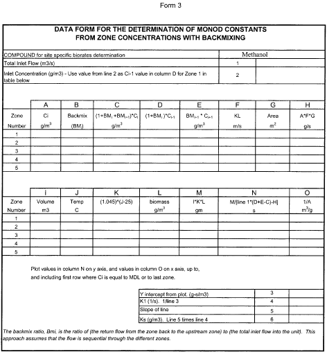
C. One Time Determination of a Single Value of Ks (Initial
Performance Test)
A single value of Ks is calculated using Form 3 for each data
set that is collected during the initial performance test. A single
composite value of Ks, deemed to be representative of the
biological unit, is subsequently selected so that the fbio values
calculated by the procedures in this appendix (using this single
value of Ks) for the data sets collected during the initial
performance test are within 10 percent of the fbio value determined
by using Form 1 with these same data sets. The value of Ks meeting
these criteria is obtained by the following steps:
(1) Determine the median of the Ks values calculated for each
data set;
(2) Estimate fbio for each data set using the selected Ks value
(Form 1 and Form 2);
(3) Calculate fbio for each data set using Form 1; and
(4) Compare the fbio values obtained in steps (2) and (3); if
the fbio value calculated using step (2) differs from that
calculated using step (3) by more than 10 percent, adjust Ks
(decrease Ks if the fbio value is lower than that calculated by
Form 1 and vice versa) and repeat this procedure starting at step
(2). If a negative value is obtained for the values of Ks, then
this negative kinetic constant may not be used with the Monod
model. If a negative value of Ks is obtained, this test procedure
cannot be used for evaluating the performance of the open
biological treatment unit.
D. Confirmation of Monod Kinetics (Initial Performance Test)
(1) Confirmation that the unit can be represented by Monod
kinetics is made by identifying the following two items:
(i) The zone methanol concentrations measured during the initial
performance test; and
(ii) The zone methanol concentrations estimated by the Multiple
Zone Concentrations Calculations Procedure based on inlet and
outlet concentrations (Column A of Form 2). For each zone, the
concentration in item 1 is compared to the concentration in item
2.
(2) For each zone, the estimated value of item 2 must be:
(i) Within 25 percent of item 1 when item 1 exceeds 8 mg/L;
or
(ii) Within 2 mg/L of item 1 when item 1 is 8 mg/L or less.
(3) Successful demonstration that the calculated zone
concentrations meet these criteria must be achieved for 80 percent
of the performance test data sets.
(4) If negative values are obtained for the values of K1 and Ks,
then these negative kinetic constants may not be used with the
Monod model, even if the criteria are met. If negative values are
obtained, this test procedure cannot be used for evaluating the
performance of the open biological treatment unit.
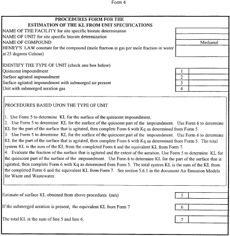
E. Determination of KL for Each Zone (Unsafe Sampling Conditions)
(1) A site-specific liquid-phase mass transfer coefficient (KL)
must be obtained for each zone during the unsafe sampling
conditions. Do not use a default value for KL. The KL value for
each zone must be based on the site-specific parameters of the
specific unit. The first step in using this procedure is to
calculate KL for each zone in the unit using Form 4. Form 4
outlines the procedure to follow for using mass transfer equations
to determine KL. Form 4 identifies the appropriate form to use for
providing the detailed calculations to support the estimate of the
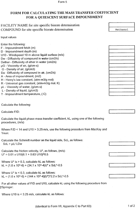
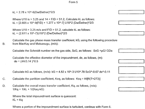
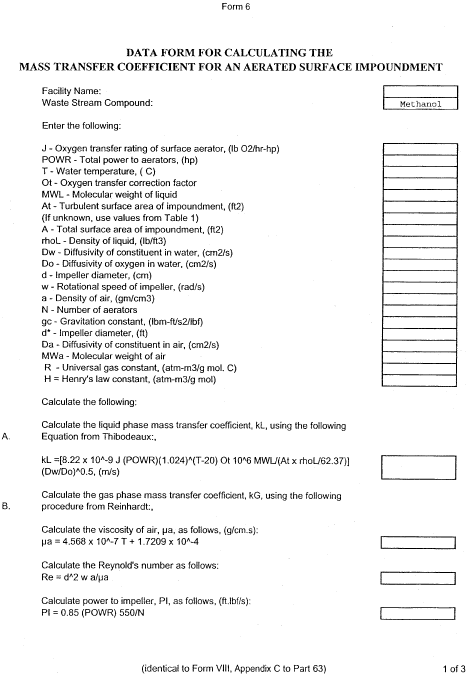
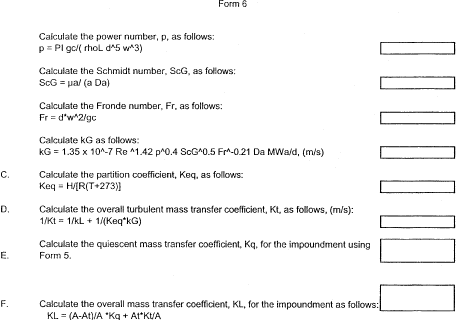
value of KL. Forms 5 and 6 are used to provide individual compound
estimates of KL for quiescent and aerated impoundments,
respectively. A computer model may be used to perform the
calculations. If the WATER8 model or the most recent update to this
model is used, then report the computer model input parameters that
you used as an attachment to Form 4. In addition, the Bay Area
Sewage Toxics Emission (BASTE) model, version 3.0, or equivalent
upgrade and the TOXCHEM (Environment Canada's Wastewater Technology
Centre and Environmega, Ltd.) model, version 1.10, or equivalent
upgrade may also be used to determine KL for the open biological
treatment unit with the following stipulations:
(i) The programs must be altered to output a KL value that is
based on the site-specific parameters of the unit modeled; and
(ii) The Henry's law value listed in Form 4 must be substituted
for the existing Henry's law values in the models.
(2) The Henry's law value listed in Form 4 may be obtained from
the following sources:
(i) Values listed by EPA with temperature adjustment if
needed;
(ii) Measured values for the system of concern with temperature
adjustment; or
(iii) Literature values of Henry's law values for methanol,
adjusted for temperature if needed.
(3) Input values used in the model and corresponding output
values shall become part of the documentation of the fbio
determination. The owner or operator should be aware that these
models may not provide equivalent KL values for some types of
units. To obtain an equivalent KL value in this situation, the
owner or operator shall either use the appropriate procedure on
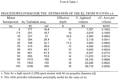
Form 4 or adjust the KL value from the model to the equivalent KL
value as described on Form 4.
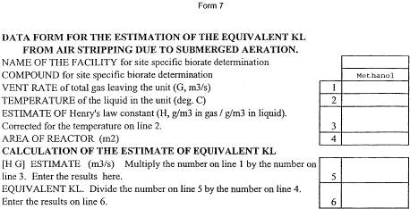
(4) Report the input parameters that you used in the computer
model on Forms 5, 6, and 7 as an attachment to Form 4. If you have
submerged air flow in your unit, you must add the value of KL
estimated on Form 7 to the value of KL obtained with Forms 5 and 6
before using the value of KL with Form 2.
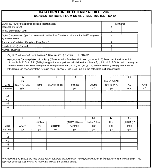
F. Estimation of Zone Concentrations (Unsafe Sampling Conditions)
Form 2 is used to estimate the zone concentrations of HAP based
on the inlet and outlet data. The value of Ks entered on the form
is that single composite value of Ks discussed in section III.C of
this appendix. This value of Ks is calculated during the Initial
Performance Test (and subsequently updated, if necessary). A unique
value of the biorate K1 is entered on line 5 of Form 2, and the
inlet concentration is estimated in Column A of Form 2. The inlet
concentration is located in the row of Form 2 corresponding to zone
0. If there are three zones in the system, n-3 equals 0 for the
inlet concentration row. These estimated zone concentrations are
then used in Form 1 to estimate f bio for the treatment unit.
G. Quality Control/Quality Assurance (QA/QC)
A QA/QC plan outlining the procedures used to determine the
measured inlet and outlet concentrations during unsafe conditions
and how the zone characterization data were obtained during the
initial performance test shall be prepared and submitted with the
initial performance test report. The plan should include, but may
not be limited to:
(1) A description of each of the sampling methods that were used
(method, procedures, time, method to avoid losses during sampling
and holding, and sampling procedures) including simplified
schematic drawings;
(2) A description of how that biomass was sampled from the
biotreatment unit, including methods, locations, and times;
(3) A description of what conditions (DO, temperature, etc.) are
important, what the target values are in the zones, how the factors
were controlled, and how they were monitored. These conditions are
primarily used to establish that the conditions of the initial
performance test correspond to the conditions of the day in
question;
(4) A description of how each analytical measurement was
conducted, including preparation of solutions, dilution procedures,
sampling procedures, monitoring of conditions, etc;
(5) A description of the analytical instrumentation used, how
the instruments were calibrated, and a summary of the accuracy and
precision for each instrument;
(6) A description of the test methods used to determine HAP
concentrations and other measurements. Section 63.457(c)(3)
specifies the test methods that must be used to determine HAP
concentrations. During unsafe sampling conditions, you do not have
to sample over an extended period of time or obtain more than one
sample at each sample point.
(7) A description of how data are captured, recorded, and
stored; and
(8) A description of the equations used and their solutions for
sampling and analysis, including a reference to any software used
for calculations and/or curve-fitting.
IV. Calculation of Individual fbio (Unsafe Sampling Conditions)
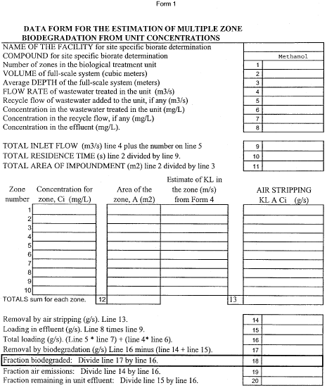
Use Form 1 with your zone concentration information to estimate
the value of f bio under unsafe sampling conditions. Form 1 uses
measured concentrations of HAP in the unit inlet and outlet, and
Form 1 also uses the estimated concentrations in each zone of the
unit obtained from Form 2. This procedure may be used on an open
biological treatment unit that has defined zones within the unit.
Use Form 1 to determine fbio for each open biological treatment
unit as it exists under subpart S of part 63. The first step in
using Form 1 is to calculate KL for each zone in the unit using
Form 4. Form 7 must also be used if submerged aeration is used.
After KL is determined using field data, obtain the concentrations
of the HAP in each zone. In this alternative procedure for unsafe
sampling conditions, the actual measured concentrations of the HAP
in each zone are replaced with the zone concentrations that are
estimated with Form 2. After KL and the zone concentrations are
determined, Form 1 is used to estimate the overall unit Fe and fbio
for methanol.
[65 FR 80765, Dec.
22, 2000]