Appendix C to Subpart UUUUU of Part 63 - PM Monitoring Provisions
40:16.0.1.1.1.8.214.29.45 : Appendix C
Appendix C to Subpart UUUUU of Part 63 - PM Monitoring Provisions
1. General Provisions
1.1 Applicability. These monitoring provisions apply to
the continuous measurement of filterable PM emissions from affected
EGUs under this subpart. A PM CEMS is used together with other CMS
and (as applicable) parametric measurement devices to quantify PM
emissions in units of the applicable standard (i.e.,
lb/MMBtu or lb/MWh).
1.2 Initial Certification and Recertification
Procedures.
You, as the owner or operator of an affected EGU that uses a PM
CEMS to demonstrate compliance with a filterable PM emissions limit
in Table 1 or 2 to this subpart must certify and, if applicable,
recertify the CEMS according to PS-11 in appendix B to part 60 of
this chapter.
1.3 Quality Assurance and Quality Control Requirements.
You must meet the applicable quality assurance requirements of
Procedure 2 in appendix F to part 60 of this chapter.
1.4 Missing Data Procedures. You must not substitute data
for missing data from the PM CEMS. Any process operating hour for
which quality-assured PM concentration data are not obtained is
counted as an hour of monitoring system downtime.
1.5 Adjustments for Flow System Bias. When the PM
emission rate is reported on a gross output basis, you must not
adjust the data recorded by a stack gas flow rate monitor for bias,
which may otherwise be required under section 75.24 of this
chapter.
2. Monitoring of PM Emissions
2.1 Monitoring System Installation Requirements. Flue
gases from the affected EGUs under this subpart vent to the
atmosphere through a variety of exhaust configurations including
single stacks, common stack configurations, and multiple stack
configurations. For each of these configurations, 40 CFR
63.10010(a) specifies the appropriate location(s) at which to
install CMS. These CMS installation provisions apply to the PM CEMS
and to the other CMS and parametric monitoring devices that provide
data for the PM emissions calculations in section 6 of this
appendix.
2.2 Primary and Backup Monitoring Systems. In the
electronic monitoring plan described in section 7 of this appendix,
you must create and designate a primary monitoring system for PM
and for each additional parameter (i.e., stack gas flow
rate, CO2 or O2 concentration, stack gas moisture content, as
applicable). The primary system must be used to report hourly PM
concentration values when the system is able to provide
quality-assured data, i.e., when the system is “in control.”
However, to increase data availability in the event of a primary
monitoring system outage, you may install, operate, maintain, and
calibrate a redundant backup monitoring system. A redundant backup
system is one that is permanently installed at the unit or stack
location and is kept on “hot standby” in case the primary
monitoring system is unable to provide quality-assured data. You
must represent each redundant backup system as a unique monitoring
system in the electronic monitoring plan. You must certify each
redundant backup monitoring system according to the applicable
provisions in section 4 of this appendix. In addition, each
redundant monitoring system must meet the applicable on-going QA
requirements in section 5 of this appendix.
3. PM Emissions Measurement Methods
The following definitions, equipment specifications, procedures,
and performance criteria are applicable
3.1 Definitions. All definitions specified in section 3
of PS-11 in appendix B to part 60 of this chapter and section 3 of
Procedure 2 in appendix F to part 60 of this chapter are applicable
to the measurement of filterable PM emissions from electric utility
steam generating units under this subpart. In addition, the
following definitions apply:
3.1.1 Stack operating hour means a clock hour during
which flue gases flow through a particular stack or duct (either
for the entire hour or for part of the hour) while the associated
unit(s) are combusting fuel.
3.1.2 Unit operating hour means a clock hour during which
a unit combusts any fuel, either for part of the hour or for the
entire hour.
3.2 Continuous Monitoring Methods.
3.2.1 Installation and Measurement Location. You must install
the PM CEMS according to 40 CFR 63.10010 and Section 2.4 of
PS-11.
3.2.2 Units of Measure. For the purposes of this subpart, you
shall report hourly PM concentrations in units of measure that
correspond to your PM CEMS correlation curve (e.g., mg/acm,
mg/acm @ 160 °C, mg/wscm, mg/dscm).
3.2.3 Other Necessary Data Collection. To convert hourly PM
concentrations to the units of the applicable emissions standard
(i.e., lb/MMBtu or lb/MWh), you must collect additional data
as described in sections 3.2.3.1 and 3.2.3.2 of this appendix. You
must install, certify, operate, maintain, and quality-assure any
stack gas flow rate, CO2, O2, or moisture monitoring systems needed
for this purpose according to sections 4 and 5 of this appendix.
The calculation methods for the emission limits described in
sections 3.2.3.1 and 3.2.3.2 of this appendix are presented in
section 6 of this appendix.
3.2.3.1 Heat Input-Based Emission Limits. To demonstrate
compliance with a heat input-based PM emission limit in Table 2 to
this subpart, you must provide the hourly stack gas CO2 or O2
concentration, along with a fuel-specific Fc factor or dry-basis
F-factor and (if applicable) the stack gas moisture content, in
order to convert measured PM concentrations values to the units of
the standard.
3.2.3.2 Gross Output-Based Emission Limits. To demonstrate
compliance with a gross output-based PM emission limit in Table 1
or Table 2 to this subpart, you must provide the hourly gross
output in megawatts, along with data from a certified stack gas
flow rate monitor and (if applicable) the stack gas moisture
content, in order to convert measured PM concentrations values to
units of the standard.
4. Certification and Recertification Requirements
4.1 Certification Requirements. You must certify your PM
CEMS and the other CMS used to determine compliance with the
applicable emissions standard before the PM CEMS can be used to
provide data under this subpart. Redundant backup monitoring
systems (if used) are subject to the same certification
requirements as the primary systems.
4.1.1 PM CEMS. You must certify your PM CEMS according to PS-11
in appendix B to part 60 of this chapter. A PM CEMS that has been
installed and certified according to PS-11 as a result of another
state or federal regulatory requirement or consent decree prior to
the effective date of this subpart shall be considered certified
for this subpart if you can demonstrate that your PM CEMS meets the
PS-11 acceptance criteria based on the applicable emission standard
in this subpart.
4.1.2 Flow Rate, Diluent Gas, and Moisture Monitoring Systems.
You must certify the continuous monitoring systems that are needed
to convert PM concentrations to units of the standard or (if
applicable) to convert the measured PM concentrations from wet
basis to dry basis or vice-versa (i.e., stack gas flow rate,
diluent gas (CO2 or O2) concentration, or moisture monitoring
systems), in accordance with the applicable provisions in section
75.20 of this chapter and appendix A to part 75 of this
chapter.
4.1.3 Other Parametric Measurement Devices. Any temperature or
pressure measurement devices that are used to convert hourly PM
concentrations to standard conditions must be installed,
calibrated, maintained, and operated according to the
manufacturers' instructions.
4.2 Recertification.
4.2.1 You must recertify your PM CEMS if it is either: moved to
a different stack or duct; moved to a new location within the same
stack or duct; modified or repaired in such a way that the existing
correlation is altered or impacted; or replaced.
4.2.2 The flow rate, diluent gas, and moisture monitoring
systems that are used to convert PM concentration to units of the
emission standard are subject to the recertification provisions in
section 75.20(b) of this chapter.
4.3 Development of a New or Revised Correlation Curve.
You must develop a new or revised correlation curve if:
4.3.1 An RCA is failed and the new or revised correlation is
developed according to section 10.6 in Procedure 2 of appendix F to
part 60 of this chapter; or
4.3.2 The events described in paragraph (1) or (2) in section
8.8 of PS-11 occur.
5. Ongoing Quality Assurance (QA) and Data Validation
5.1 PM CEMS.
5.1.1 Required QA Tests. Following initial certification, you
must conduct periodic QA testing of each primary and (if
applicable) redundant backup PM CEMS. The required QA tests and the
PS that must be met are found in Procedure 2 of appendix F to part
60 of this chapter (Procedure 2). Except as otherwise provided in
section 5.1.2 of this appendix, the QA tests shall be done at the
frequency specified in Procedure 2.
5.1.2 RRA and RCA Test Frequencies.
5.1.2.1 The test frequency for RRAs of the PM CEMS shall be
annual, i.e., once every 4 calendar quarters. The RRA must
either be performed within the fourth calendar quarter after the
calendar quarter in which the previous RRA was completed or in a
grace period (see section 5.1.3, below). When a required annual RRA
is done within a grace period, the deadline for the next RRA is 4
calendar quarters after the quarter in which the RRA was originally
due, rather than the calendar quarter in which the grace period
test is completed.
5.1.2.2 The test frequency for RCAs of the PM CEMS shall be
triennial, i.e., once every 12 calendar quarters. If a
required RCA is not completed within 12 calendar quarters after the
calendar quarter in which the previous RCA was completed, it must
be performed in a grace period immediately following the twelfth
calendar quarter (see section 5.1.3, below). When an RCA is done in
a grace period, the deadline for the next RCA shall be 12 calendar
quarters after the calendar quarter in which the RCA was originally
due, rather than the calendar quarter in which the grace period
test is completed.
5.1.2.3 Successive quarterly audits (i.e., ACAs and, if
applicable, sample volume audits (SVAs)) shall be conducted at
least 60 days apart.
5.1.3 Grace Period. A grace period is available, immediately
following the end of the calendar quarter in which an RRA or RCA of
the PM CEMS is due. The length of the grace period shall be the
lesser of 720 EGU (or stack) operating hours or 1 calendar
quarter.
5.1.4 RCA and RRA Acceptability. The results of your RRA or RCA
are considered acceptable provided that the criteria in section
10.4(5) of Procedure 2 in appendix F to part 60 of this chapter are
met for an RCA or section 10.4(6) of Procedure 2 in appendix F to
part 60 of this chapter are met for an RRA.
5.1.5 Data Validation. Your PM CEMS is considered to be
out-of-control, and you may not report data from it as
quality-assured, when, for a required certification,
recertification, or QA test, the applicable acceptance criterion
(either in PS-11 in appendix B to part 60 of this chapter or
Procedure 2 in appendix F to part 60 of this chapter) is not met.
Further, data from your PM CEMS are considered out-of-control, and
may not be used for reporting, when a required QA test is not
performed on schedule or within an allotted grace period. When an
out-of-control period occurs, you must perform the appropriate
follow-up actions. For an out-of-control period triggered by a
failed QA test, you must perform and pass the same type of test in
order to end the out-of-control period. For a QA test that is not
performed on time, data from the PM CEMS remain out-of-control
until the required test has been performed and passed. You must
count all out-of-control data periods of the PM CEMS as hours of
monitoring system downtime.
5.2 Stack Gas Flow Rate, Diluent Gas, and Moisture Monitoring
Systems. The on-going QA test requirements and data validation
criteria for the primary and (if applicable) redundant backup stack
gas flow rate, diluent gas, and moisture monitoring systems are
specified in appendix B to part 75 of this chapter.
5.3 QA/QC Program Requirements. You must develop and
implement a QA/QC program for the PM CEMS and the other equipment
that is used to provide data under this subpart. You may store your
QA/QC plan electronically, provided that the information can be
made available expeditiously in hard copy to auditors and
inspectors.
5.3.1 General Requirements.
5.3.1.1 Preventive Maintenance. You must keep a written record
of the procedures needed to maintain the PM CEMS and other
equipment that is used to provide data under this subpart in proper
operating condition, along with a schedule for those procedures. At
a minimum, you must include all procedures specified by the
manufacturers of the equipment and, if applicable, additional or
alternate procedures developed for the equipment.
5.3.1.2 Recordkeeping Requirements. You must keep a written
record describing procedures that will be used to implement the
recordkeeping and reporting requirements of this appendix.
5.3.1.3 Maintenance Records. You must keep a record of all
testing, maintenance, or repair activities performed on the PM
CEMS, and other equipment used to provide data under this subpart
in a location and format suitable for inspection. You may use a
maintenance log for this purpose. You must maintain the following
records for each system or device: The date, time, and description
of any testing, adjustment, repair, replacement, or preventive
maintenance action performed, and records of any corrective actions
taken. Additionally, you must record any adjustment that may affect
the ability of a monitoring system or measurement device to make
accurate measurements, and you must keep a written explanation of
the procedures used to make the adjustment(s).
5.3.2 Specific Requirements for the PM CEMS.
5.3.2.1 Daily, and Quarterly Quality Assurance Assessments. You
must keep a written record of the procedures used for daily
assessments of the PM CEMS. You must also keep records of the
procedures used to perform quarterly ACA and (if applicable) SVA
audits. You must document how the test results are calculated and
evaluated.
5.3.2.2 Monitoring System Adjustments. You must document how
each component of the PM CEMS will be adjusted to provide correct
responses after routine maintenance, repairs, or corrective
actions.
5.3.2.3 Correlation Tests, Annual and Triennial Audits. You must
keep a written record of procedures used for the correlation
test(s), annual RRAs, and triennial RCAs of the PM CEMS. You must
document how the test results are calculated and evaluated.
5.3.3 Specific Requirements for Diluent Gas, Stack Gas Flow
Rate, and Moisture Monitoring Systems. The QA/QC program
requirements for the stack gas flow rate, diluent gas, and moisture
monitoring systems described in section 3.2.3 of this appendix are
specified in section 1 of appendix B to part 75 of this
chapter.
5.3.4 Requirements for Other Monitoring Equipment. For the
equipment required to convert readings from the PM CEMS to standard
conditions (e.g., devices to measure temperature and
pressure), you must keep a written record of the calibrations
and/or other procedures used to ensure that the devices provide
accurate data.
5.3.5 You may store your QA/QC plan electronically, provided
that you can make the information available expeditiously in hard
copy to auditors or inspectors.
6. Data Reduction and Caculations
6.1 Data Reduction and Validation.
6.1.1 You must reduce the data from PM CEMS to hourly averages,
in accordance with 40 CFR 60.13(h)(2) of this chapter.
6.1.2 You must reduce all CEMS data from stack gas flow rate,
CO2, O2, and moisture monitoring systems to hourly averages
according to 40 CFR 75.10(d)(1) of this chapter.
6.1.3 You must reduce all other data from devices used to
convert readings from the PM CEMS to standard conditions to hourly
averages according to 40 CFR 60.13(h)(2) or 40 CFR 75.10(d)(1) of
this chapter. This includes, but is not limited to, data from
devices used to measure temperature and pressure, or, for
cogeneration units that calculate gross output based on steam
characteristics, devices to measure steam flow rate, steam
pressure, and steam temperature.
6.1.4 Do not calculate the PM emission rate for any unit or
stack operating hour in which valid data are not obtained for PM
concentration or for any parameter used in the PM emission rate
calculations (i.e., gross output, stack gas flow rate, stack
temperature, stack pressure, stack gas moisture content, or diluent
gas concentration, as applicable).
6.1.5 For the purposes of this appendix, part 75 substitute data
values for stack gas flow rate, CO2 concentration, O2
concentration, and moisture content are not considered to be valid
data.
6.1.6 Operating hours in which PM concentration is missing or
invalid are hours of monitoring system downtime. The use of
substitute data for PM concentration is not allowed.
6.1.7 You must exclude all data obtained during a boiler startup
or shutdown operating hour (as defined in 40 CFR 63.10042) from the
determination of the 30-boiler operating day rolling average PM
emission rates.
6.2 Calculation of PM Emission Rates. Unless your PM CEMS
is correlated to provide PM concentrations at standard conditions,
you must use the calculation methods in sections 6.2.1 through
6.2.3 of this appendix to convert measured PM concentration values
to units of the emission limit (lb/MMBtu or lb/MWh, as
applicable).
6.2.1 PM concentrations must be at standard conditions in order
to convert them to units of the emissions limit. If your PM CEMS
measures PM concentrations at standard conditions, proceed to
section 6.2.2 or 6.2.3, below (as applicable). However, if your PM
CEMS measures PM concentrations in units of mg/acm or mg/acm at a
specified temperature (e.g., 160 °C), you must first use one
of the following equations to convert the hourly PM concentration
values from actual to standard conditions:

or

Where:
Cstd = PM concentration at standard conditions Ca = PM
concentration at measurement conditions Ts = Stack Temperature (
°F) TCEMS = CEMS Measurement Temperature ( °F) PCEMS = CEMS
Measurement Pressure (in. Hg) Ps = Stack Pressure (in. Hg) Tstd =
Standard Temperature (68 °F) Pstd = Standard Pressure (29.92 in.
Hg). 6.2.2 Heat Input-Based PM Emission Rates (Existing EGUs,
Only). Calculate the hourly heat input-based PM emission rates (if
applicable), in units of lb/MMBtu, according to sections 6.2.2.1
and 6.2.2.2 of this appendix. 6.2.2.1 You must select an
appropriate emission rate equation from among Equations 19-1
through 19-9 in appendix A-7 to part 60 of this chapter to convert
the hourly PM concentration values from section 6.2.1 of this
appendix to units of lb/MMBtu. Note that the EPA test Method 19
equations require the pollutant concentration to be expressed in
units of lb/scf; therefore, you must first multiply the PM
concentration by 6.24 × 10⁻⁸ to convert it from mg/scm to lb/scf.
6.2.2.2 You must use the appropriate carbon-based or dry-basis
F-factor in the emission rate equation that you have selected. You
may either use an F-factor from Table 19-2 of EPA test Method 19 in
appendix A-7 to part 60 of this chapter or from section 3.3.5 or
section 3.3.6 of appendix F to part 75 of this chapter.
6.2.2.3 If the hourly average O2 concentration is above 14.0% O2
(19.0% for an IGCC) or the hourly average CO2 concentration is
below 5.0% CO2 (1.0% for an IGCC), you may calculate the PM
emission rate using the applicable diluent cap value (as defined in
40 CFR 63.10042 and specified in 40 CFR 63.10007(f)(1)), provided
that the diluent gas monitor is operating and recording
quality-assured data).
6.2.2.4 If your selected EPA test Method 19 equation requires a
correction for the stack gas moisture content, you may either use
quality-assured hourly data from a certified part 75 moisture
monitoring system, a fuel-specific default moisture value from 40
CFR 75.11(b) of this chapter, or a site-specific default moisture
value approved by the Administrator under section 75.66 of this
chapter.
6.2.3 Gross Output-Based PM Emission Rates. For each unit or
stack operating hour, if Cstd is measured on a wet basis, you must
use Equation C-3 to calculate the gross output-based PM emission
rate (if applicable). Use Equation C-4 if Cstd is measured on a dry
basis:

Where:
Eheo = Hourly gross output-based PM emission rate (lb/MWh) Cstd =
PM concentration from section 6.2.1 (mg/scm), wet basis Qs =
Unadjusted stack gas volumetric flow rate (scfh, wet basis) MW =
Gross output (megawatts) 6.24 × 10−8 = Conversion factor
or

Where:
Eheo = Hourly gross output-based PM emission rate (lb/MWh) Cstd =
PM concentration from section 6.2.1 (mg/scm), dry basis Qs =
Unadjusted stack gas volumetric flow rate (scfh, wet basis) MW =
Gross output (megawatts) Bws = Proportion by volume of water vapor
in the stack gas 6.24 × 10−8 = Conversion factor
6.2.4 You must calculate the 30-boiler operating day rolling
average PM emission rates according to 40 CFR 63.10021(b).
7. Recordkeeping and Reporting
7.1 Recordkeeping Provisions. For the PM CEMS and the
other necessary CMS and parameter measurement devices installed at
each affected unit or common stack, you must maintain a file of all
measurements, data, reports, and other information required by this
appendix in a form suitable for inspection, for 5 years from the
date of each record, in accordance with 40 CFR 63.10033. The file
shall contain the applicable information in sections 7.1.1 through
7.1.11 of this appendix.
7.1.1 Monitoring Plan Records. For each EGU or group of EGUs
monitored at a common stack, you must prepare and maintain a
monitoring plan for the PM CEMS and the other CMS(s) needed to
convert PM concentrations to units of the applicable emission
standard.
7.1.1.1 Updates. If you make a replacement, modification, or
change in a certified CEMS that is used to provide data under this
appendix (including a change in the automated data acquisition and
handling system (DAHS)) or if you make a change to the flue gas
handling system and that replacement, modification, or change
affects information reported in the monitoring plan (e.g., a
change to a serial number for a component of a monitoring system),
you shall update the monitoring plan.
7.1.1.2 Contents of the Monitoring Plan. For the PM CEMS, your
monitoring plan shall contain the applicable information in
sections 7.1.1.2.1 and 7.1.1.2.2 of this appendix. For required
stack gas flow rate, diluent gas, and moisture monitoring systems,
your monitoring plan shall include the applicable information
required for those systems under 40 CFR 75.53 (g) and (h) of this
chapter.
7.1.1.2.1 Electronic. Your electronic monitoring plan records
must include the following information: Unit or stack ID number(s);
unit information (type of unit, maximum rated heat input, fuel
type(s), emission controls); monitoring location(s); the monitoring
methodologies used; monitoring system information, including (as
applicable): Unique system and component ID numbers; the make,
model, and serial number of the monitoring equipment; the sample
acquisition method; formulas used to calculate emissions; operating
range and load information; monitor span and range information;
units of measure of your PM concentrations (see section 3.2.2); and
appropriate default values. Your electronic monitoring plan shall
be evaluated and submitted using the ECMPS Client Tool provided by
the Clean Air Markets Division (CAMD) in EPA's Office of
Atmospheric Programs.
7.1.1.2.2 Hard Copy. You must keep records of the following
items: Schematics and/or blueprints showing the location of the PM
monitoring system(s) and test ports; data flow diagrams; test
protocols; and miscellaneous technical justifications. The hard
copy portion of the monitoring plan must also explain how the PM
concentrations are measured and how they are converted to the units
of the applicable emissions limit. The equation(s) used for the
conversions must be documented. Electronic storage of the hard copy
portion of the monitoring plan is permitted.
7.1.2 Operating Parameter Records. You must record the following
information for each operating hour of each EGU and also for each
group of EGUs utilizing a monitored common stack, to the extent
that these data are needed to convert PM concentration data to the
units of the emission standard. For non-operating hours, you must
record only the items in sections 7.1.2.1 and 7.1.2.2 of this
appendix. If you elect to or are required to comply with a gross
output-based PM standard, for any hour in which there is gross
output greater than zero, you must record the items in sections
7.1.2.1 through 7.1.2.3 and (if applicable) 7.1.2.5 of this
appendix; however, if there is heat input to the unit(s) but no
gross output (e.g., at unit startup), you must record the
items in sections 7.1.2.1, 7.1.2.2, and, if applicable, section
7.1.2.5 of this appendix. If you elect to comply with a heat
input-based PM standard, you must record only the items in sections
7.1.2.1, 7.1.2.2, 7.1.2.4, and, if applicable, section 7.1.2.5 of
this appendix.
7.1.2.1 The date and hour;
7.1.2.2 The unit or stack operating time (rounded up to the
nearest fraction of an hour (in equal increments that can range
from 1 hundredth to 1 quarter of an hour, at your option);
7.1.2.3 The hourly gross output (rounded to nearest MWe);
7.1.2.4 If applicable, the Fc factor or dry-basis F-factor used
to calculate the heat input-based PM emission rate; and
7.1.2.5 If applicable, a flag to indicate that the hour is an
exempt startup or shutdown hour.
7.1.3 PM Concentration Records. For each affected unit or common
stack using a PM CEMS, you must record the following information
for each unit or stack operating hour:
7.1.3.1 The date and hour;
7.1.3.2 Monitoring system and component identification codes for
the PM CEMS, as provided in the electronic monitoring plan, if your
CEMS provides a quality-assured value of PM concentration for the
hour;
7.1.3.3 The hourly PM concentration, in units of measure that
correspond to your PM CEMS correlation curve, for each operating
hour in which a quality-assured value is obtained. Record all PM
concentrations with one leading non-zero digit and one decimal
place, expressed in scientific notation. Use the following rounding
convention: If the digit immediately following the first decimal
place is 5 or greater, round the first decimal place upward
(increase it by one); if the digit immediately following the first
decimal place is 4 or less, leave the first decimal place
unchanged.
7.1.3.4 A special code, indicating whether or not a
quality-assured PM concentration is obtained for the hour; and
7.1.3.5 Monitor data availability for PM concentration, as a
percentage of unit or stack operating hours calculated in the
manner established for SO2, CO2, O2 or moisture monitoring systems
according to 40 CFR 75.32 of this chapter.
7.1.4 Stack Gas Volumetric Flow Rate Records.
7.1.4.1 When a gross output-based PM emissions limit must be
met, in units of lb/MWh, you must obtain hourly measurements of
stack gas volumetric flow rate during EGU operation, in order to
convert PM concentrations to units of the standard.
7.1.4.2 When hourly measurements of stack gas flow rate are
needed, you must keep hourly records of the flow rates and related
information, as specified in 40 CFR 75.57(c)(2) of this
chapter.
7.1.5 Records of Diluent Gas (CO2 or O2) Concentration.
7.1.5.1 When a heat input-based PM emission limit must be met,
in units of lb/MMBtu, you must obtain hourly measurements of CO2 or
O2 concentration during EGU operation, in order to convert PM
concentrations to units of the standard.
7.1.5.2 When hourly measurements of diluent gas concentration
are needed, you must keep hourly CO2 or O2 concentration records,
as specified in 40 CFR 75.57(g) of this chapter.
7.1.6 Records of Stack Gas Moisture Content.
7.1.6.1 When corrections for stack gas moisture content are
needed to demonstrate compliance with the applicable PM emissions
limit:
7.1.6.1.1 If you use a continuous moisture monitoring system,
you must keep hourly records of the stack gas moisture content and
related information, as specified in 40 CFR 75.57(c)(3) of this
chapter.
7.1.6.1.2 If you use a fuel-specific default moisture value, you
must represent it in the electronic monitoring plan required under
section 7.1.1.2.1 of this appendix.
7.1.7 PM Emission Rate Records. For applicable PM emission
limits in units of lb/MMBtu or lb/MWh, you must record the
following information for each affected EGU or common stack:
7.1.7.1 The date and hour;
7.1.7.2 The hourly PM emissions rate (lb/MMBtu or lb/MWh, as
applicable), calculated according to section 6.2.2 or 6.2.3 of this
appendix, rounded to the same precision as the standard
(i.e., with one leading non-zero digit and one decimal
place, expressed in scientific notation), expressed in scientific
notation. Use the following rounding convention: If the digit
immediately following the first decimal place is 5 or greater,
round the first decimal place upward (increase it by one); if the
digit immediately following the first decimal place is 4 or less,
leave the first decimal place unchanged. You must calculate the PM
emission rate only when valid values of PM concentration and all
other required parameters required to convert PM concentration to
the units of the standard are obtained for the hour;
7.1.7.3 An identification code for the formula used to derive
the hourly PM emission rate from measurements of the PM
concentration and other necessary parameters (i.e., Equation
C-3 or C-4 in section 6.2.3 of this appendix or the applicable EPA
test Method 19 equation);
7.1.7.4 If applicable, indicate that the diluent cap has been
used to calculate the PM emission rate; and
7.1.7.5 If applicable, indicate that the default electrical load
(as defined in 40 CFR 63.10042) has been used to calculate the
hourly PM emission rate.
7.1.7.6 Indicate that the PM emission rate was not calculated
for the hour, if valid data are not obtained for PM concentration
and/or any of the other parameters in the PM emission rate
equation. For the purposes of this appendix, substitute data values
for stack gas flow rate, CO2 concentration, O2 concentration, and
moisture content reported under part 75 of this chapter are not
considered to be valid data. However, when the gross output (as
defined in 40 CFR 63.10042) is reported for an operating hour with
zero output, the default electrical load value is treated as
quality-assured data.
7.1.8 Other Parametric Data. If your PM CEMS measures PM
concentrations at actual conditions, you must keep records of the
temperatures and pressures used in Equation C-1 or C-2 to convert
the measured hourly PM concentrations to standard conditions.
7.1.9 Certification, Recertification, and Quality Assurance Test
Records. For any PM CEMS used to provide data under this subpart,
you must record the following certification, recertification, and
quality assurance information:
7.1.9.1 The test dates and times, reference values, monitor
responses, monitor full scale value, and calculated results for the
required 7-day drift tests and for the required daily zero and
upscale calibration drift tests;
7.1.9.2 The test dates and times and results (pass or fail) of
all daily system optics checks and daily sample volume checks of
the PM CEMS (as applicable);
7.1.9.3 The test dates and times, reference values, monitor
responses, and calculated results for all required quarterly
ACAs;
7.1.9.4 The test dates and times, reference values, monitor
responses, and calculated results for all required quarterly SVAs
of extractive PM CEMS;
7.1.9.5 The test dates and times, reference method readings and
corresponding PM CEMS responses (including the units of measure),
and the calculated results for all PM CEMS correlation tests, RRAs
and RCAs. For the correlation tests, you must indicate which model
is used (i.e., linear, logarithmic, exponential, polynomial,
or power) and record the correlation equation. For the RRAs and
RCAs, the reference method readings and PM CEMS responses must be
reported in the same units of measure as the PM CEMS
correlation;
7.1.9.6 The cycle time and sample delay time for PM CEMS that
operate in batch sampling mode; and
7.1.9.7 Supporting information for all required PM CEMS
correlation tests, RRAs, and RCAs, including records of all raw
reference method and monitoring system data, the results of sample
analyses to substantiate the reported test results, as well as
records of sampling equipment calibrations, reference monitor
calibrations, and analytical equipment calibrations.
7.1.10 For stack gas flow rate, diluent gas, and moisture
monitoring systems, you must keep records of all certification,
recertification, diagnostic, and on-going quality-assurance tests
of these systems, as specified in 40 CFR 75.59(a) of this
chapter.
7.1.11 For each temperature measurement device (e.g.,
resistance temperature detector or thermocouple) and pressure
measurement device used to convert measured PM concentrations to
standard conditions according to Equation C-1 or C-2, you must keep
records of all calibrations and other checks performed to ensure
that accurate data are obtained.
7.2 Reporting Requirements.
7.2.1 General Reporting Provisions. You must comply with the
following requirements for reporting PM emissions from each
affected EGU (or group of EGUs monitored at a common stack) under
this subpart:
7.2.1.1 Notifications, in accordance with section 7.2.2 of this
appendix;
7.2.1.2 Monitoring plan reporting, in accordance with section
7.2.3 of this appendix;
7.2.1.3 Certification, recertification, and quality assurance
test submittals, in accordance with section 7.2.4 of this appendix;
and
7.2.1.4 Electronic quarterly emissions report submittals, in
accordance with section 7.2.5 of this appendix.
7.2.2 Notifications. You must provide notifications for each
affected unit (or group of units monitored at a common stack) under
this subpart in accordance with 40 CFR 63.10030.
7.2.3 Monitoring Plan Reporting. For each affected unit (or
group of units monitored at a common stack) under this subpart
using PM CEMS to measure PM emissions, you must make electronic and
hard copy monitoring plan submittals as follows:
7.2.3.1 For an EGU that begins reporting hourly PM
concentrations on January 1, 2024, with a previously certified PM
CEMS, submit the monitoring plan information in section 7.1.1.2 of
this appendix prior to or concurrent with the first required
quarterly emissions report. For a new EGU, or for an EGU switching
to continuous monitoring of PM emissions after having implemented
another allowable compliance option under this subpart, submit the
information in section 7.1.1.2 of this appendix at least 21 days
prior to the start of initial certification testing of the PM CEMS.
Also submit the monitoring plan information in 40 CFR 75.53(g)
pertaining to any required flow rate, diluent gas, and moisture
monitoring systems within the applicable time frame specified in
this section, if the required records are not already in place.
7.2.3.2 Whenever an update of the monitoring plan is required,
as provided in section 7.1.1.1 of this appendix, you must submit
the updated information either prior to or concurrent with the
relevant quarterly electronic emissions report.
7.2.3.3 All electronic monitoring plan submittals and updates
shall be made to the Administrator using the ECMPS Client Tool.
Hard copy portions of the monitoring plan shall be submitted to the
appropriate delegated authority.
7.2.4 Certification, Recertification, and Quality-Assurance Test
Reporting. Except for daily quality assurance tests of the required
monitoring systems (i.e., calibration error or drift tests,
sample volume checks, system optics checks, and flow monitor
interference checks), you must submit the results of all required
certification, recertification, and quality-assurance tests
described in sections 7.1.9.1 through 7.1.9.6 and 7.1.10 of this
appendix electronically (except for test results previously
submitted, e.g., under the Acid Rain Program), using the
ECMPS Client Tool. Submit the results of the quality assurance test
(i.e., RCA or RRA) or, if applicable, a new PM CEMS
correlation test, either prior to or concurrent with the relevant
quarterly electronic emissions report. If this is not possible, you
have up to 60 days after the test completion date to submit the
test results; in this case, you may claim provisional status for
the emissions data affected by the quality assurance test or
correlation, starting from the date and hour in which the test was
completed and continuing until the date and hour in which the test
results are submitted. For an RRA or RCA, if the applicable audit
specifications are met, the status of the emissions data in the
relevant time period changes from provisional to quality-assured,
and no further action is required. For a successful correlation
test, apply the correlation equation retrospectively to the raw
data to change the provisional status of the data to
quality-assured, and resubmit the affected emissions report(s).
However, if the applicable performance specifications are not met,
the provisional data must be invalidated, and resubmission of the
affected quarterly emission report(s) is required. For a failed RRA
or RCA, you must take corrective actions and proceed according to
the applicable requirements found in sections 10.5 through 10.7 of
Procedure 2 until a successful quality assurance test report is
submitted. If a correlation test is unsuccessful, you may not
report quality-assured data from the PM CEMS until the results of a
subsequent correlation test show that the specifications in section
13.0 of PS 11 are met.
7.2.5 Quarterly Reports.
7.2.5.1 For each affected EGU (or group of EGUs monitored at a
common stack), the owner or operator must use the ECMPS Client Tool
to submit electronic quarterly emissions reports to the
Administrator, in an XML format specified by the Administrator,
starting with a report for the later of:
7.2.5.1.1 The first calendar quarter of 2024; or
7.2.5.1.2 The calendar quarter in which the initial PM CEMS
correlation test is completed.
7.2.5.2 You must submit the electronic reports within 30 days
following the end of each calendar quarter, except for EGUs that
have been placed in long-term cold storage (as defined in section
72.2 of this chapter).
7.2.5.3 Each of your electronic quarterly reports shall include
the following information:
7.2.5.3.1 The date of report generation;
7.2.5.3.2 Facility identification information;
7.2.5.3.3 The information in sections 7.1.2 through 7.1.7 of
this appendix that is applicable to your PM emission measurement
methodology; and
7.2.5.3.4 The results of all daily quality assurance
assessments, i.e., calibration drift checks and (if
applicable) sample volume checks of the PM CEMS, calibration error
tests of the other continuous monitoring systems that are used to
convert PM concentration to units of the standard, and (if
applicable) flow monitor interference checks.
7.2.5.4 Compliance Certification. Based on a reasonable inquiry
of those persons with primary responsibility for ensuring that all
PM emissions from the affected unit(s) under this subpart have been
correctly and fully monitored, the owner or operator must submit a
compliance certification in support of each electronic quarterly
emissions monitoring report. The compliance certification shall
include a statement by a responsible official with that official's
name, title, and signature, certifying that, to the best of his or
her knowledge, the report is true, accurate, and complete.
[85 FR 55769, Sept. 9, 2020]
Appendix C to Part 63 - Determination of the Fraction Biodegraded (Fbio) in a Biological Treatment Unit
40:16.0.1.1.1.46.325.36.124 : Appendix C
Appendix C to Part 63 - Determination of the Fraction Biodegraded
(Fbio) in a Biological Treatment Unit I. Purpose
The purpose of this appendix is to define the procedures for an
owner or operator to use to calculate the site specific fraction of
organic compounds biodegraded (Fbio) in a biological treatment
unit. If an acceptable level of organic compounds is destroyed
rather than emitted to the air or remaining in the effluent, the
biological treatment unit may be used to comply with the applicable
treatment requirements without the unit being covered and vented
through a closed vent system to an air pollution control
device.
The determination of Fbio shall be made on a system as it would
exist under the rule. The owner or operator should anticipate
changes that would occur to the wastewater flow and concentration
of organics, to be treated by the biological treatment unit, as a
result of enclosing the collection and treatment system as required
by the rule.
Unless otherwise specified, the procedures presented in this
appendix are designed to be applied to thoroughly mixed treatment
units. A thoroughly mixed treatment unit is a unit that is designed
and operated to approach or achieve uniform biomass distribution
and organic compound concentration throughout the aeration unit by
quickly dispersing the recycled biomass and the wastewater entering
the unit. Detailed discussion on how to determine if a biological
treatment unit is thoroughly mixed can be found in reference 7.
Systems that are not thoroughly mixed treatment units should be
subdivided into a series of zones that have uniform characteristics
within each zone. The number of zones required to characterize a
biological treatment system will depend on the design and operation
of the treatment system. Detailed discussion on how to determine
the number of zones in a biological treatment unit and examples of
determination of f bio can be found in reference 8. Each zone
should then be modeled as a separate unit. The amount of air
emissions and biodegradation from the modeling of these separate
zones can then be added to reflect the entire system.
II. Definitions
Biological treatment unit = wastewater treatment unit designed
and operated to promote the growth of bacteria to destroy organic
materials in wastewater.
fbio = The fraction of individual applicable organic compounds in
the wastewater biodegraded in a biological treatment unit. Fbio =
The fraction of total applicable organic compounds in the
wastewater biodegraded in a biological treatment unit. Fe = The
fraction of applicable organic compounds emitted from the
wastewater to the atmosphere. K1 = First order biodegradation rate
constant, L/g MLVSS-hr KL = liquid-phase mass transfer coefficient,
m/s M = compound specific mass flow weighted average of organic
compounds in the wastewater, Mg/Yr III. Procedures for
Determination of fbio
The first step in the analysis to determine if a biological
treatment unit may be used without being covered and vented through
a closed-vent system to an air pollution control device is to
determine the compound-specific fbio. The following procedures may
be used to determine fbio:
(1) The EPA Test Method 304A or 304B (appendix A, part 63) -
Method for the Determination of Biodegradation Rates of Organic
Compounds,
(2) Performance data with and without biodegradation,
(3) Inlet and outlet concentration measurements,
(4) Batch tests,
(5) Multiple zone concentration measurements.
All procedures must be executed so that the resulting fbio is
based on the collection system and waste management units being in
compliance with the rule. If the collection system and waste
management units meet the suppression requirements at the time of
the test, any of the procedures may be chosen. If the collection
system and waste management units are not in compliance at the time
of the performance test, then only Method 304A, B, or the batch
test shall be chosen. If Method 304A, B, or the batch test is used,
any anticipated changes to the influent of the full-scale
biological treatment unit that will occur after the facility has
enclosed the collection system must be represented in the influent
feed to the benchtop bioreactor unit, or test unit.
Select one or more appropriate procedures from the five listed
above based on the availability of site specific data and the type
of mixing that occurs in the unit (thoroughly mixed or multiple
mixing zone). If the facility does not have site-specific data on
the removal efficiency of its biological treatment unit, then
Procedure 1 or Procedure 4 may be used. Procedure 1 allows the use
of a benchtop bioreactor to determine the first-order
biodegradation rate constant. An owner or operator may elect to
assume the first order biodegradation rate constant is zero for any
regulated compound(s) present in the wastewater. Procedure 4
explains two types of batch tests which may be used to estimate the
first order biodegradation rate constant. An owner or operator may
elect to assume the first order biodegradation rate constant is
zero for any regulated compound(s) present in the wastewater.
Procedure 3 would be used if the facility has, or measures to
determine, data on the inlet and outlet individual organic compound
concentration for the biological treatment unit. Procedure 3 may
only be used on a thoroughly mixed treatment unit. Procedure 5 is
the concentration measurement test that can be used for units with
multiple mixing zones. Procedure 2 is used if a facility has or
obtains performance data on a biotreatment unit prior to and after
addition of the microbial mass. An example where Procedure 2 could
be used is an activated sludge unit where measurements have been
taken on inlet and exit concentration of organic compounds in the
wastewater prior to seeding with the microbial mass and startup of
the unit. The flow chart in figure 1 outlines the steps to use for
each of the procedures.
A. Method 304A or 304B (Procedure 1)
If the first procedure is selected, follow the instructions in
appendix A of part 63 Method 304A “Method for the Determination of
Biodegradation Rates of Organic Compounds (Vented Option)” or
Method 304B “Method for the Determination of Biodegradation Rates
of Organic Compounds (Scrubber Option).” Method 304A or 304B
provides instruction on setting up and operating a self-contained
benchtop bioreactor system which is operated under conditions
representative of the target full-scale system. Method 304A uses a
benchtop bioreactor system with a vent, and uses modeling to
estimate any air emissions. Method 304B uses a benchtop bioreactor
system which is equipped with a scrubber and is not vented.
There are some restrictions on which method a source may use. If
the facility is measuring the rate of biodegradation of compounds
that may tend to react or hydrolyze in the scrubber of Method 304B,
this method shall not be used and Method 304A is the required
method. If a Henry's law value is not available to use with Form V,
then Method 304A shall not be used and Method 304B is the required
method. When using either method, the feed flow to the benchtop
bioreactor shall be representative of the flow and concentration of
the wastewater that will be treated by the full-scale biological
treatment unit after the collection and treatment system has been
enclosed as required under the applicable subpart.
The conditions under which the full-scale biological treatment
unit is run establish the operating parameters of Method 304A or
304B. If the biological treatment unit is operated under abnormal
operating conditions (conditions outside the range of critical
parameters examined and confirmed in the laboratory), the EPA
believes this will adversely affect the biodegradation rate and is
an unacceptable treatment option. The facility would be making
multiple runs of the test method to simulate the operating range
for its biological treatment unit. For wide ranges of variation in
operating parameters, the facility shall demonstrate the biological
treatment unit is achieving an acceptable level of control, as
required by the regulation, across the ranges and not only at the
endpoints.
If Method 304A is used, complete Form V initially. Form V is
used to calculate K1 from the Method 304A results. Form V uses the
Henry's law constant to estimate the fraction lost from the
benchtop reactor vent. The owner or operator shall use the Henry's
law values in Table I. Form V also gives direction for calculating
an equivalent KL. Note on Form V if the calculated number for line
11 is greater than the calculated value for line 13, this procedure
shall not be used to demonstrate the compound is biodegradable. If
line 11 is greater than line 13, this is an indication the fraction
emitted from the vent is greater than the fraction biodegraded. The
equivalent KL determined on Form V is used in Form II (line 6).
Estimation of the Fe and fbio must be done following the steps in
Form III. Form III uses the previously calculated values of K1 and
KL (equivalent KL), and site-specific parameters of the full-scale
bioreactor as input to the calculations. Forms II, III, and V must
be completed for each organic compound in the wastewater to
determine Fe and fbio.
If Method 304B is used, perform the method and use the
measurements to determine K1, which is the first-order
biodegradation rate constant. Form I lists the sequence of steps in
the procedure for calculating K1 from the Method 304B results. Once
K1 is determined, KL must be calculated by use of mass transfer
equations. Form II outlines the procedure to follow for use of mass
transfer equations to determine KL. A computer program which
incorporates these mass transfer equations may be used. Water7 is a
program that incorporates these mass transfer equations and may be
used to determine KL. Refer to Form II-A to determine KL, if Water7
or the most recent update to this model is used. In addition, the
Bay Area Sewage Toxics Emission (BASTE) model version 3.0 or
equivalent upgrade and the TOXCHEM (Environment Canada's Wastewater
Technology Centre and Environmega, Ltd.) model version 1.10 or
equivalent upgrade may also be used to determine KL for the
biological treatment unit with several stipulations. The programs
must be altered to output a KL value which is based on the
site-specific parameters of the unit modeled, and the Henry's law
values listed in Table I must be substituted for the existing
Henry's law values in the programs. Input values used in the model
and corresponding output values shall become documentation of the
fbio determination. The owner or operator should be aware these
programs do not allow modeling of certain units. To model these
units, the owner or operator shall use one of the other appropriate
procedures as outlined in this appendix. The owner or operator
shall not use a default value for KL. The KL value determined by
use of these models shall be based on the site-specific parameters
of the specific unit. This KL value shall be inserted in Form II
(line 6). Estimation of the Fe and fbio must be done following the
steps in Form III. Form III uses the previously calculated values
of K1 and KL, and site-specific parameters of the full-scale
bioreactor as input to the calculations. Forms I, II, and III must
be completed for each organic compound in the wastewater to
determine Fe and fbio.
B. Performance Data With and Without Biodegradation (Procedure 2)
Procedure 2 uses site-specific performance data that represents
or characterizes operation of the unit both with and without
biodegradation. As previously mentioned, proper determination of
fbio must be made on a system as it would exist under the rule.
Using Form IV, calculate KL and K1. After KL and K1 are determined,
Form III is used to calculate Fe and fbio for each organic compound
present in the wastewater.
C. Inlet and Outlet Concentration Measurements (Procedure 3)
Procedure 3 uses measured inlet and outlet organic compound
concentrations for the unit. This procedure may only be used on a
thoroughly mixed treatment unit. Again, proper determination of
fbio must be made on a system as it would exist under the rule. The
first step in using this procedure is to calculate KL using Form
II. A computer model may be used. If the Water7 model or the most
recent update to this model is used, then use Form II-A to
calculate KL. After KL is determined using field data, complete
Form VI to calculate K1. The TOXCHEM or BASTE model may also be
used to calculate KL for the biological treatment unit, with the
stipulations listed in procedure 304B. After KL and K1 are
determined, Form III is used to calculate Fe and fbio for each
organic compound.
D. Batch Tests (Procedure 4)
Two types of batch tests which may be used to determine kinetic
parameters are: (1) The aerated reactor test and (2) the sealed
reactor test. The aerated reactor test is also known as the BOX
test (batch test with oxygen addition). The sealed reactor test is
also known as the serum bottle test. These batch tests should be
conducted only by persons familiar with procedures for determining
biodegradation kinetics. Detailed discussions of batch procedures
for determining biodegradation kinetic parameters can be found in
references 1-4.
For both batch test approaches, a biomass sample from the
activated sludge unit of interest is collected, aerated, and stored
for no more than 4 hours prior to testing. To collect sufficient
data when biodegradation is rapid, it may be necessary to dilute
the biomass sample. If the sample is to be diluted, the biomass
sample shall be diluted using treated effluent from the activated
sludge unit of interest to a concentration such that the
biodegradation test will last long enough to make at least six
concentration measurements. It is recommended that the tests not be
terminated until the compound concentration falls below the limit
of quantitation (LOQ). Measurements that are below the LOQ should
not be used in the data analysis. Biomass concentrations shall be
determined using standard methods for measurement of mixed liquor
volatile suspended solids (MLVSS) (reference 5).
The change in concentration of a test compound may be monitored
by either measuring the concentration in the liquid or in the
reactor headspace. The analytical technique chosen for the test
should be as sensitive as possible. For the batch test procedures
described in this section, equilibrium conditions must exist
between the liquid and gas phases of the experiments because the
data analysis procedures are based on this premise. To use the
headspace sampling approach, the reactor headspace must be in
equilibrium with the liquid so that the headspace concentrations
can be correlated with the liquid concentrations. Before the
biodegradation testing is conducted, the equilibrium assumption
must be verified. A discussion of the equilibrium assumption
verification is given below in sections D.1 and D.2 since different
approaches are required for the two types of batch tests.
To determine biodegradation kinetic parameters in a batch test,
it is important to choose an appropriate initial substrate
(compound(s) of interest) concentration for the test. The outcome
of the batch experiment may be influenced by the initial substrate
(SO) to biomass (XO) ratio (see references 3, 4, and 6). This ratio
is typically measured in chemical oxygen demand (COD) units. When
the SO/XO ratio is low, cell multiplication and growth in the batch
test is negligible and the kinetics measured by the test are
representative of the kinetics in the activated sludge unit of
interest. The SO/XO ratio for a batch test is determined with the
following equation:
Where: SO/XO = initial substrate to biomass
ratio on a COD basis Si = initial substrate concentration in COD
units (g COD/L) X = biomass concentration in the batch test (g
MLVSS/L) 1.42 = Conversion factor to convert to COD units
For the batch tests described in this section, the SO/XO ratio
(on a COD basis) must be initially less than 0.5.
1. Aerated Reactor Test. An aerated draft tube reactor
may be used for the biokinetics testing (as an example see Figure 2
of appendix C). Other aerated reactor configurations may also be
used. Air is bubbled through a porous frit at a rate sufficient to
aerate and keep the reactor uniformly mixed. Aeration rates
typically vary from 50 to 200 ml/min for a 1 liter system. A mass
flow rate controller is used to carefully control the air flow rate
because it is important to have an accurate measure of this rate.
The dissolved oxygen (DO) concentration in the system must not fall
below 2 mg/liter so that the biodegradation observed will not be
DO-limited. Once the air flow rate is established, the test mixture
(or compound) of interest is then injected into the reactor and the
concentration of the compound(s) is monitored over time.
Concentrations may be monitored in the liquid or in the headspace.
A minimum of six samples shall be taken over the period of the
test. However, it is necessary to collect samples until the
compound concentration falls below the LOQ. If liquid samples are
collected, they must be small enough such that the liquid volume in
the batch reactor does not change by more than 10%.
Before conducting experiments with biomass, it is necessary to
verify the equilibrium assumption. The equilibrium assumption can
be verified by conducting a stripping experiment using the effluent
(no biomass) from the activated sludge unit of interest. Effluent
is filtered with a 0.45 um or smaller filter and placed in the
draft tube reactor. Air is sparged into the system and the compound
concentration in the liquid or headspace is monitored over time.
This test with no biomass may provide an estimate of the Henry's
law constant. If the system is at equilibrium, the Henry's law
constant may be estimated with the following equation:
Where: C = cencentration at time, t (min) CO =
concentration at t = 0 G = volumetric gas flow rate (ml/min) V =
liquid volume in the batch reactor (ml) Keq = Henry's law constant
(mg/L-gas)/(mg/L-liquid) t = time (min)
A plot of - ln(C/Co) as a function of t will have a slope equal
to GKeq/V. The equilibrium assumption can be verified by comparing
the experimentally determined Keq for the system to literature
values of the Henry's Law constant (including those listed in this
appendix). If Keq does not match the Henry's law constant, Keq
shall be determined from analysis of the headspace and liquid
concentration in a batch system.
The concentration of a compound decreases in the bioreactor due
to both biodegradation and stripping. Biodegradation processes are
typically described with a Monod model. This model and a stripping
expression are combined to give a mass balance for the aerated
draft tube reactor):
Where: s = test compound concentration,
mg/liter G = volumetric gas flow rate, liters/hr Keq = Henry's Law
constant measured in the system, (mg/liter gas)/(mg/liter liquid) V
= volume of liquid in the reactor, liters X = biomass concentration
(g MLVSS/liter) Qm = maximum rate of substrate removal, mg/g
MLVSS/hr KS = Monod biorate constant at half the maximum rate,
mg/liter
Equation App. C-3 can be integrated to obtain the following
equation:
Where: A = GKeqKs + QmVX B = GKeq So = test
compound concentration at t = 0
This equation is used along with the substrate concentration
versus time data to determine the best fit parameters (Qm and KS)
to describe the biodegradation process in the aerated reactor. If
the aerated reactor test is used, the following procedure is used
to analyze the data. Evaluate Keq for the compound of interest with
Form XI. The concentration in the vented headspace or liquid is
measured as a function of time and the data is entered on Form XI.
A plot is made from the data and attached to the Form XI. Keq is
calculated on Form XI and the results are contrasted with the
expected value of Henry's law obtained from Form IX. If the
comparison is satisfactory, the stripping constant is calculated
from Keq, completing Form XI. The values of Keq may differ because
the theoretical value of Keq may not be applicable to the system of
interest. If the comparison of the calculated Keq from the form and
the expected value of Henry's law is unsatisfactory, Form X can
alternatively be used to validate Keq. If the aerated reactor is
demonstrated to not be at equilibrium, either modify the reactor
design and/or operation, or use another type of batch test.
The compound-specific biorate constants are then measured using
Form XII. The stripping constant that was determined from Form XI
and a headspace correction factor of 1 are entered on Form XII. The
aerated reactor biotest may then be run, measuring concentrations
of each compound of interest as a function of time. If headspace
concentrations are measured instead of liquid concentrations, then
the corresponding liquid concentrations are calculated from the
headspace measurements using the Keq determined on Form XI and
entered on Form XII.
The concentration data on Form XII may contain scatter that can
adversely influence the data interpretation. It is possible to
curve fit the concentration data and enter the concentrations on
the fitted curve instead of the actual data. If curve fitting is
used, the curve-fitting procedure must be based upon the Equation
App. C-4. When curve fitting is used, it is necessary to attach a
plot of the actual data and the fitted curve to Form XII.
If the stripping rate constant is relatively large when compared
to the biorate at low concentrations, it may be difficult to obtain
accurate evaluations of the first-order biorate constant. In these
cases, either reducing the stripping rate constant by lowering the
aeration rate, or increasing the biomass concentrations should be
considered.
The final result of the batch testing is the measurement of a
biorate that can be used to estimate the fraction biodegraded,
fbio. The number transferred to Form III is obtained from Form XII,
line 9.
2. Sealed Reactor Test. This test uses a closed system to
prevent losses of the test compound by volatilization. This test
may be conducted using a serum bottle or a sealed draft tube
reactor (for an example see Figure 3 of appendix C). Since no air
is supplied, it is necessary to ensure that sufficient oxygen is
present in the system. The DO concentration in the system must not
fall below 2 mg/liter so that the biodegradation observed will not
be DO-limited. As an alternative, oxygen may be supplied by
electrolysis as needed to maintain the DO concentration above 2
mg/liter. The reactor contents must be uniformly mixed, by stirring
or agitation using a shaker or similar apparatus. The test mixture
(or compound) of interest is injected into the reactor and the
concentration is monitored over time. A minimum of six samples
shall be taken over the period of the test. However, it is
necessary to monitor the concentration until it falls below the
LOQ.
The equilibrium assumption must be verified for the batch
reactor system. In this case, Keq may be determined by
simultaneously measuring gas and liquid phase concentrations at
different times within a given experiment. A constant ratio of
gas/liquid concentrations indicates that equilibrium conditions are
present and Keq is not a function of concentration. This ratio is
then taken as the Keq for the specific compound in the test. It is
not necessary to measure Keq for each experiment. If the ratio is
not constant, the equilibrium assumption is not valid and it is
necessary to (1) increase mixing energy for the system and retest
for the equilibrium assumption, or (2) use a different type of test
(for example, a collapsible volume reactor).
The concentration of a compound decreases in the bioreactor due
to biodegradation according to Equation App. C-5:
Where: s = test compound concentration
(mg/liters) Vl = the average liquid volume in the reactor (liters)
Vg = the average gas volume in the reactor (liters) Qm = maximum
rate of substrate removal (mg/g
ML VSS/hr) Keq = Henry's Law
constant determined for the test, (mg/liter gas)/(mg/liter liquid)
Ks = Monod biorate constant at one-half the maximum rate (mg/liter)
t = time (hours) X = biomass concentration (g
ML VSS/liter)
so = test compound concentration at time t = 0
Equation App. C-5 can be solved analytically to give:
This equation is used along with the substrate concentration
versus time data to determine the best fit parameters (Qm and Ks)
to describe the biodegradation process in the sealed reactor.
If the sealed reactor test is used, Form X is used to determine
the headspace correction factor. The disappearance of a compound in
the sealed reactor test is slowed because a fraction of the
compound is not available for biodegradation because it is present
in the headspace. If the compound is almost entirely in the liquid
phase, the headspace correction factor is approximately one. If the
headspace correction factor is substantially less than one,
improved mass transfer or reduced headspace may improve the
accuracy of the sealed reactor test. A preliminary sealed reactor
test must be conducted to test the equilibrium assumption. As the
compound of interest is degraded, simultaneous headspace and liquid
samples should be collected and Form X should be used to evaluate
Keq. The ratio of headspace to liquid concentrations must be
constant in order to confirm that equilibrium conditions exist. If
equilibrium conditions are not present, additional mixing or an
alternate reactor configuration may be required.
The compound-specific biorate constants are then calculated
using Form XII. For the sealed reactor test, a stripping rate
constant of zero and the headspace correction factor that was
determined from Form X are entered on Form XII. The sealed reactor
test may then be run, measuring the concentrations of each compound
of interest as a function of time. If headspace concentrations are
measured instead of liquid concentrations, then the corresponding
liquid concentrations are calculated from the headspace
measurements using Keq from Form X and entered on Form XII.
The concentration data on Form XII may contain scatter that can
adversely influence the data interpretation. It is possible to
curve fit the concentration data and enter the concentrations on
the fitted curve instead of the actual data. If curve fitting is
used, the curve-fitting procedure must be based upon Equation App.
C-6. When curve fitting is used, it is necessary to attach a plot
of the actual data and the fitted curve to Form XII.
If a sealed collapsible reactor is used that has no headspace,
the headspace correction factor will equal 1, but the stripping
rate constant may not equal 0 due to diffusion losses through the
reactor wall. The ratio of the rate of loss of compound to the
concentration of the compound in the reactor (units of per hour)
must be evaluated. This loss ratio has the same units as the
stripping rate constant and may be entered as the stripping rate
constant on line 1 of Form XII.
If the loss due to diffusion through the walls of the
collapsible reactor is relatively large when compared to the
biorate at low concentrations, it may be difficult to obtain
accurate evaluations of the first-order biorate constant. In these
cases, either replacing the materials used to construct the reactor
with materials of low permeability or increasing the biomass
concentration should be considered.
The final result of the batch testing is the measurement of a
biorate that can be used to estimate the fraction biodegraded,
fbio. The number transferred to Form III is obtained from Form XII,
line 9.
The number on Form XII line 9 will equal the Monod first-order
biorate constant if the full-scale system is operated in the
first-order range. If the full-scale system is operated at
concentrations above that of the Monod first-order range, the value
of the number on line 9 will be somewhat lower than the Monod
first-order biorate constant. With supporting biorate data, the
Monod model used in Form XII may be used to estimate the effective
biorate constant K1 for use in Form III.
If a reactor with headspace is used, analysis of the data using
equation App. C-6 is valid only if Vl and Vg do not change more
than 10% (i.e., they can be approximated as constant for the
duration of the test). Since biodegradation is occurring only in
the liquid, as the liquid concentration decreases it is necessary
for mass to transfer from the gas to the liquid phase. This may
require vigorous mixing and/or reducing the volume in the headspace
of the reactor.
If there is no headspace (e.g., a collapsible reactor), equation
App. C-6 is independent of V1 and there are no restrictions on the
liquid volume. If a membrane or bag is used as the
collapsible-volume reactor, it may be important to monitor for
diffusion losses in the system. To determine if there are losses,
the bag should be used without biomass and spiked with the
compound(s) of interest. The concentration of the compound(s) in
the reactor should be monitored over time. The data are analyzed as
described above for the sealed reactor test.
3. Quality Control/Quality Assurance (QA/QC). A QA/QC
plan outlining the procedures used to determine the biodegradation
rate constants shall be prepared and a copy maintained at the
source. The plan should include, but may not be limited to:
1. A description of the apparatus used (e.g., size, volume,
method of supplying air or oxygen, mixing, and sampling procedures)
including a simplified schematic drawing.
2. A description of how biomass was sampled from the activated
sludge unit.
3. A description of how biomass was held prior to testing (age,
etc.).
4. A description of what conditions (DO, gas-liquid equilibrium,
temperature, etc.) are important, what the target values are, how
the factors were controlled, and how well they were controlled.
5. A description of how the experiment was conducted, including
preparation of solutions, dilution procedures, sampling procedures,
monitoring of conditions, etc.
6. A description of the analytical instrumentation used, how the
instruments were calibrated, and a summary of the precision for
that equipment.
7. A description of the analytical procedures used. If
appropriate, reference to an ASTM, EPA or other procedure may be
used. Otherwise, describe how the procedure is done, what is done
to measure precision, accuracy, recovery, etc., as appropriate.
8. A description of how data are captured, recorded, and
stored.
9. A description of the equations used and their solutions,
including a reference to any software used for calculations and/or
curve-fitting.
E. Multiple Zone Concentration Measurements (Procedure 5)
Procedure 5 is the concentration measurement method that can be
used to determine the fbio for units that are not thoroughly mixed
and thus have multiple zones of mixing. As with the other
procedures, proper determination of fbio must be made on a system
as it would exist under the rule. For purposes of this calculation,
the biological unit must be divided 1 into zones with uniform
characteristics within each zone. The number of zones that is used
depends on the complexity of the unit. Reference 8, “Technical
Support Document for the Evaluation of Aerobic Biological Treatment
Units with Multiple Mixing Zones,” is a source for further
information concerning how to determine the number of zones that
should be used for evaluating your unit. The following information
on the biological unit must be available to use this procedure:
basic unit variables such as inlet and recycle wastewater flow
rates, type of agitation, and operating conditions; measured
representative organic compound concentrations in each zone and the
inlet and outlet; and estimated mass transfer coefficients for each
zone.
1 This is a mathematical division of the actual unit; not
addition of physical barriers.
Reference 8 “Technical Support Document for the Evaluation of
Aerobic Biological Treatment Units with Multiple Mixing Zones,” is
a source for further information concerning how to interpolate the
biorates for multiple zones. In units with well-characterized
concentration measurements obtained in an initial evaluation of the
unit, it may be possible to demonstrate that there is a good
correlation of the component concentrations with the locations in
the multiple-zone unit. With this good correlation, it may be
possible to accurately predict the concentrations in selected zones
without actually testing each selected zone. This correlation
method may be used for units that have many zones (greater than 5)
or where one of the interior zones is not readily accessible for
sampling. To use this correlation method of estimating zone
concentrations, it is necessary to measure the concentrations in
the inlet unit, the exit unit, and sufficient interior units to
obtain a correlation of component concentrations with the
locations. You cannot use this correlation method of estimating
selected zone concentrations if monitoring of each zone is
required, or if the accuracy and precision of the correlation is
inferior to actual individual sampling error. The accuracy and
precision of the correlation may be improved by increasing the
number of locations tested. Because the correlation is based on
many samples, it should provide an accurate representation of a
stable operating system.
The estimated mass transfer coefficient for each compound in
each zone is obtained from Form II using the characteristics of
each zone. A computer model may be used. If the Water7 model or the
most recent update to this model is used, then use Form II-A to
calculate KL. The TOXCHEM or BASTE model may also be used to
calculate KL for the biological treatment unit, with the
stipulations listed in Procedure 304B. Compound concentration
measurements for each zone are used in Form XIII to calculate the
fbio. A copy of Form XIII is completed for each of the compounds of
concern treated in the biological unit.
IV. Calculation of Fbio
At this point, the individual fbios determined by the previously
explained procedures must be summed to obtain the total Fbio. To
determine the Fbio multiply each compound specific fbio by the
compound-specific average mass flow rate of the organic compound in
the wastewater stream (see regulation for instruction on
calculation of average mass flow rate). Sum these products and
divide by the total wastewater stream average mass flow rate of
organic compounds.
M = compound specific average mass flow rate of
the organic compounds in the wastewater (Mg/Yr) n = number of
organic compounds in the wastewater
The Fbio is then used in the applicable compliance equations in
the regulation to determine if biodegradation may be used to comply
with the treatment standard without covering and venting to an air
pollution control device.
References
1. Rajagopalan, S. et al. “Comparison of Methods for Determining
Biodegradation Kinetics of Volatile Organic Compounds.” Proceedings
of Water Environment Federation. 67th Annual Conference, October
15-19, 1994.
2. Ellis, T.G. et al. “Determination of Toxic Organic Chemical
Biodegradation Kinetics Using Novel Respirometric Technique”.
Proceedings Water Environment Federation, 67th Annual Conference,
October 15-19, 1994.
3. Pitter, P. and J. Chudoba. Biodegradability of Organic
Substances in the Aquatic Environment. CRC Press, Boca Raton, FL.
1990.
4. Grady, C.P.L., B. Smets, and D. Barbeau. Variability in
kinetic parameter estimates: A review of possible causes and a
proposed terminology. Wat. Res. 30 (3), 742-748, 1996.
5. Eaton, A.D., et al. eds., Standard Methods for the
Examination of Water and Wastewater, 19th Edition, American Public
Health Association, Washington, DC, 1995.
6. Chudoba P., B. Capdeville, and J. Chudoba. Explanation of
biological meaning of the So/Xo ratio in batch cultivation. Wat.
Sci. Tech. 26 (3/4), 743-751, 1992.
7. Technical Support Document for Evaluation of Thoroughly Mixed
Biological Treatment Units. November 1998.
8. Technical Support Document for the Evaluation of Aerobic
Biological Treatment Units with Multiple Mixing Zones. July
1999.
| Compound |
HL @ 25 °C (atm/mole
frac) |
HL @ 100 °C (atm/mole
frac) |
| 1
Acetaldehyde |
4.87e + 00 |
5.64e + 01 |
| 3
Acetonitrile |
1.11e + 00 |
1.78e + 01 |
| 4
Acetophenone |
5.09e−01 |
2.25e + 01 |
| 5 Acrolein |
4.57e + 00 |
6.61e + 01 |
| 8
Acrylonitrile |
5.45e + 00 |
6.67e + 01 |
| 9 Allyl
chloride |
5.15e + 02 |
2.26e + 03 |
| 10 Aniline |
9.78e−02 |
1.42e + 00 |
| 12 Benzene |
3.08e + 02 |
1.93e + 03 |
| 14 Benzyl
chloride |
1.77e + 01 |
2.88e + 02 |
| 15 Biphenyl |
2.27e + 01 |
1.27e + 03 |
| 17 Bromoform |
2.96e + 01 |
3.98e + 02 |
| 18
1,3-Butadiene |
3.96e + 03 |
1.56e + 04 |
| 20 Carbon
disulfide |
1.06e + 03 |
3.60e + 03 |
| 21 Carbon
tetrachloride |
1.68e + 03 |
1.69e + 04 |
| 23
2-Chloroacetophenone |
4.84e−02 |
1.43e + 01 |
| 24
Chlorobenzene |
2.09e + 02 |
3.12e + 03 |
| 25 Chloroform |
2.21e + 02 |
1.34e + 03 |
| 26
Chloroprene |
5.16e + 01 |
1.74e + 02 |
| 29 o-Cresol |
9.12e−02 |
2.44e + 01 |
| 31 Cumene |
7.28e + 02 |
7.15e + 03 |
| 32
1,4-Dichlorobenzene(p) |
1.76e + 02 |
1.95e + 03 |
| 33 Dichloroethyl
ether |
1.14e + 00 |
3.57e + 01 |
| 34
1,3-Dichloropropene |
1.97e + 02 |
1.44e + 03 |
| 36
N,N-Dimethylaniline |
7.70e−01 |
5.67e + 02 |
| 37 Diethyl
sulfate |
3.41e−01 |
4.22e + 01 |
| 38
3,3′-Dimethylbenzidine |
7.51e−05 |
5.09e−01 |
| 40
1,1-Dimethylhydrazine |
9.11e−02 |
1.57e + 01 |
| 42 Dimethyl
sulfate |
2.23e−01 |
1.43e + 01 |
| 43
2,4-Dinitrophenol |
2.84e−01 |
1.50e + 02 |
| 44
2,4-Dinitrotoluene |
4.00e−01 |
9.62e + 00 |
| 45
1,4-Dioxane |
3.08e−01 |
9.53e + 00 |
| 47
Epichlorohydrin |
1.86e + 00 |
4.34e + 01 |
| 48 Ethyl
acrylate |
1.41e + 01 |
3.01e + 02 |
| 49
Ethylbenzene |
4.38e + 02 |
4.27e + 03 |
| 50 Ethyl chloride
(chloroethane) |
6.72e + 02 |
3.10e + 03 |
| 51 Ethylene
dibromide |
3.61e + 01 |
5.15e + 02 |
| 52 Ethylene
dichloride (1,2-Dichloroethane) |
6.54e + 01 |
5.06e + 02 |
| 54 Ethylene
oxide |
1.32e + 01 |
9.09e + 01 |
| 55 Ethylidene
dichloride (1,1-Dichloroethane) |
3.12e + 02 |
2.92e + 03 |
| 57 Ethylene glycol
dimethyl ether |
1.95e + 00 |
4.12e + 01 |
| 60 Ethylene glycol
monoethyl ether acetate |
9.86e−02 |
6.03e + 00 |
| 62 Ethylene glycol
monomethyl ether acetate |
1.22e−01 |
6.93e + 00 |
| 64 Diethylene
glycol dimethyl ether |
8.38e−02 |
4.69e + 00 |
| 69 Diethylene
glycol diethyl ether |
1.19e−01 |
7.71e + 00 |
| 72 Ethylene glycol
monobutyl ether acetate |
2.75e−01 |
2.50e + 01 |
| 73
Hexachlorobenzene |
9.45e + 01 |
2.57e + 04 |
| 74
Hexachlorobutadiene |
5.72e + 02 |
6.92e + 03 |
| 75
Hexachloroethane |
4.64e + 02 |
7.49e + 04 |
| 76 Hexane |
4.27e + 04 |
9.44e + 04 |
| 78 Isophorone |
3.68e−01 |
1.68e + 01 |
| 80 Methanol |
2.89e−01 |
7.73e + 00 |
| 81 Methyl bromide
(Bromomethane) |
3.81e + 02 |
2.12e + 03 |
| 82 Methyl chloride
(Chloromethane) |
4.90e + 02 |
2.84e + 03 |
| 83 Methyl
chloroform (1,1,1-Trichloroethane) |
9.67e + 02 |
5.73e + 03 |
| 84 Methyl ethyl
ketone (2-Butanone) |
7.22e + 00 |
5.92e + 01 |
| 86 Methyl isobutyl
ketone (Hexone) |
2.17e + 01 |
3.72e + 02 |
| 88 Methyl
methacrylate |
7.83e + 00 |
9.15e + 01 |
| 89 Methyl
tert-butyl ether |
3.08e + 01 |
2.67e + 02 |
| 90 Methylene
chloride (Dichloromethane) |
1.64e + 02 |
9.15e + 02 |
| 93
Naphthalene |
2.68e + 01 |
7.10e + 02 |
| 94
Nitrobenzene |
1.33e + 00 |
2.80e + 01 |
| 96
2-Nitropropane |
6.61e + 00 |
8.76e + 01 |
| 99 Phosgene |
7.80e + 02 |
3.51e + 03 |
| 102
Propionaldehyde |
3.32e + 00 |
1.42e + 02 |
| 103 Propylene
dichloride |
1.59e + 02 |
1.27e + 03 |
| 104 Propylene
oxide |
1.98e + 01 |
1.84e + 02 |
| 106 Styrene |
1.45e + 02 |
1.72e + 03 |
| 107
1,1,2,2-Tetrachloroethane |
1.39e + 01 |
1.99e + 02 |
| 108
Tetrachloroethylene (Perchloroethylene) |
9.83e + 02 |
1.84e + 04 |
| 109 Toluene |
3.57e + 02 |
2.10e + 03 |
| 112
o-Toluidine |
1.34e−01 |
1.15e + 01 |
| 113
1,2,4-Trichlorobenzene |
1.07e + 02 |
1.04e + 03 |
| 114
1,1,2-Trichloroethane |
4.58e + 01 |
5.86e + 02 |
| 115
Trichloroethylene |
5.67e + 02 |
7.66e + 03 |
| 116
2,4,5-Trichlorophenol |
4.84e−01 |
6.27e + 01 |
| 117
Triethylamine |
6.94e + 00 |
2.57e + 02 |
| 118
2,2,4-Trimethylpentane |
1.85e + 05 |
9.74e + 05 |
| 119 Vinyl
acetate |
2.82e + 01 |
2.80e + 02 |
| 120 Vinyl
chloride |
1.47e + 03 |
6.45e + 03 |
| 121 Vinylidene
chloride (1,1-Dichloroethylene) |
1.44e + 03 |
1.40e + 04 |
| 123 m-Xylene |
4.13e + 02 |
3.25e + 03 |
| 124 o-Xylene |
2.71e + 02 |
2.55e + 03 |
| 125 p-Xylene |
4.13e + 02 |
3.20e + 03 |
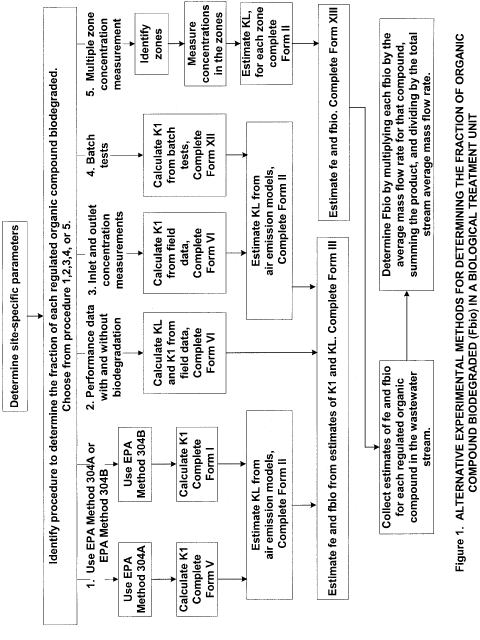
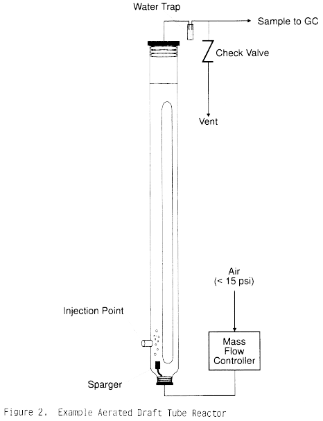
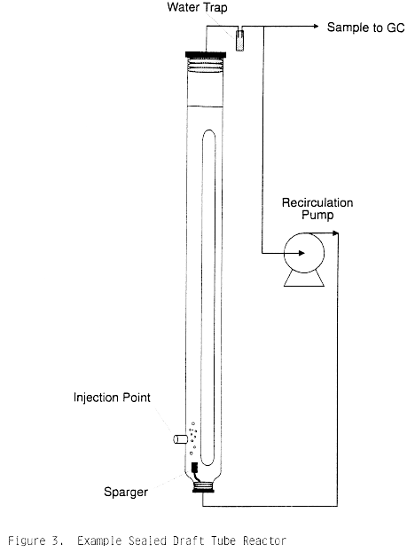
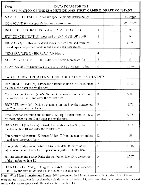
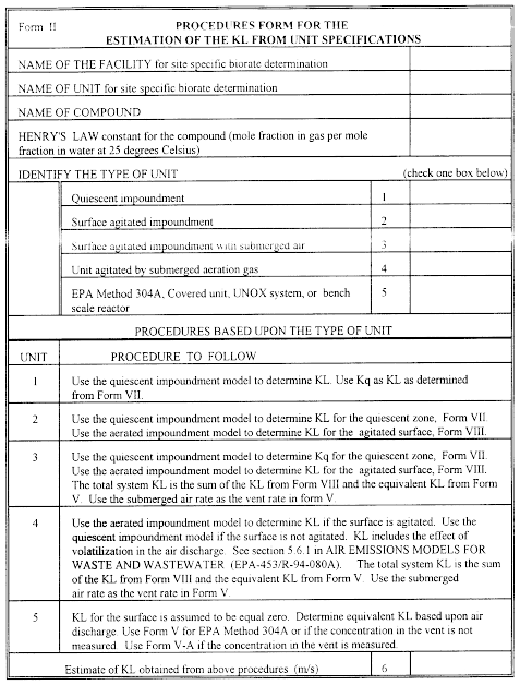
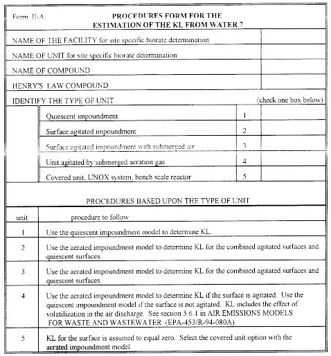
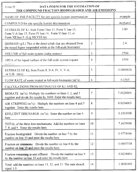
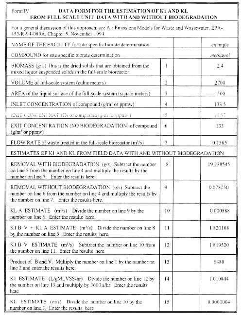
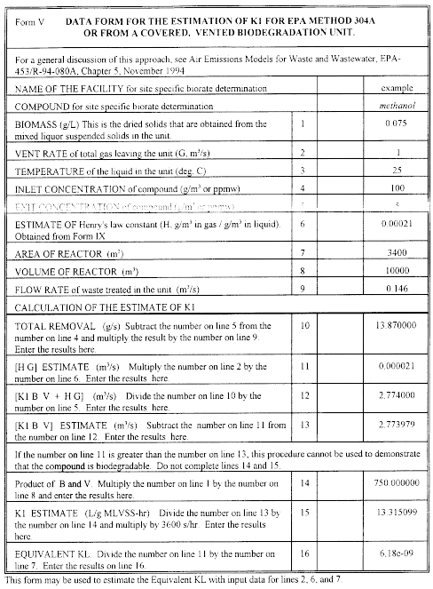
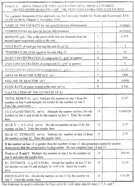
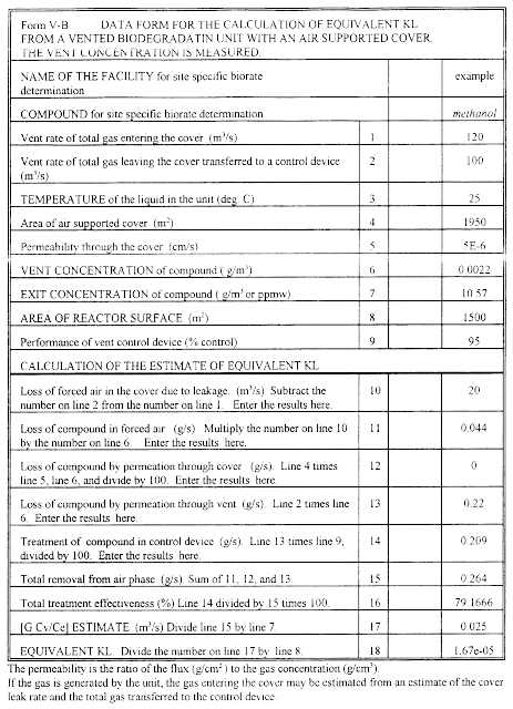
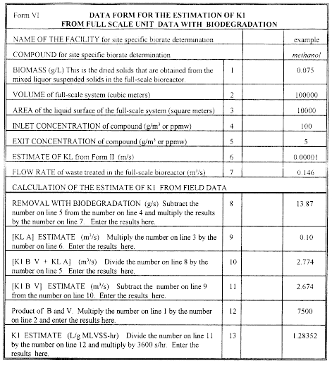
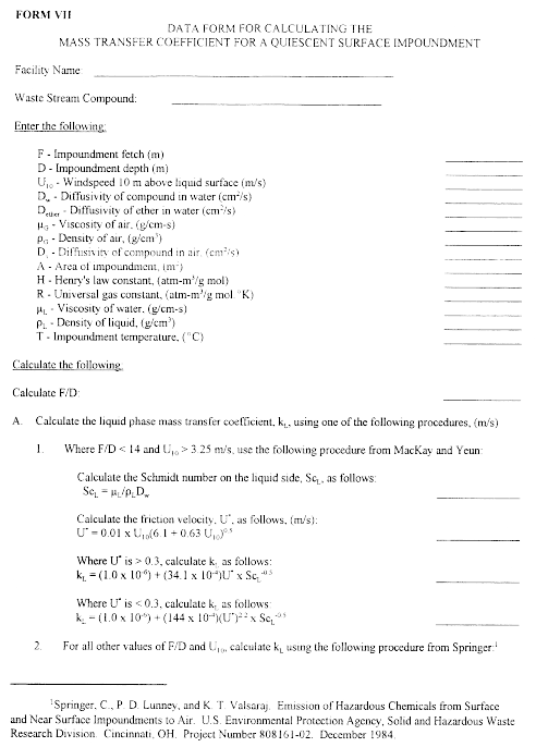
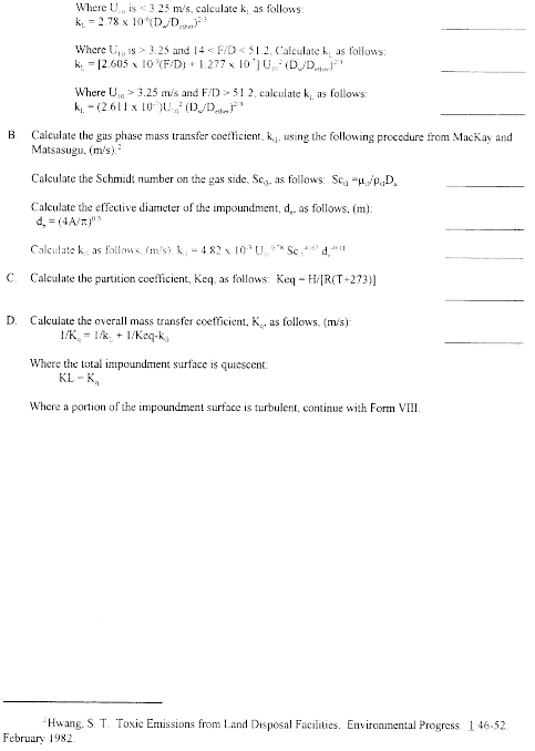
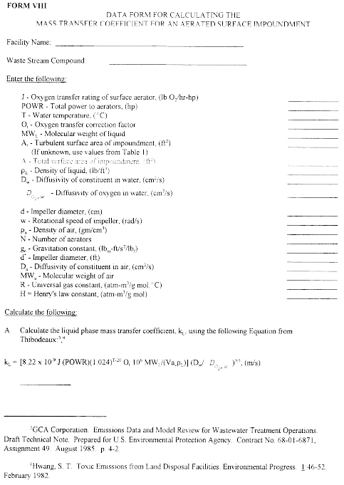

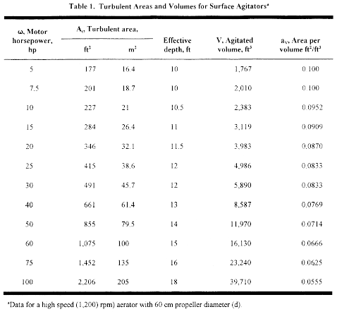
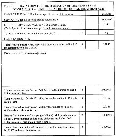
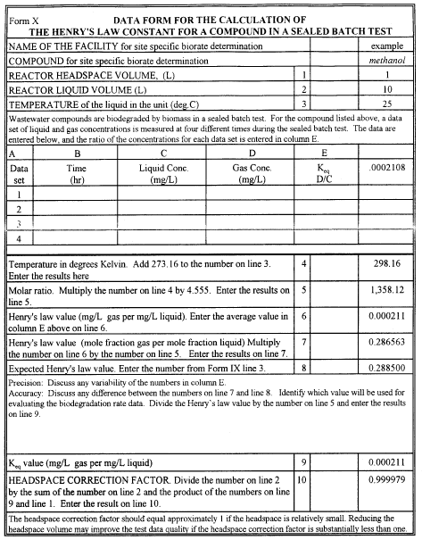
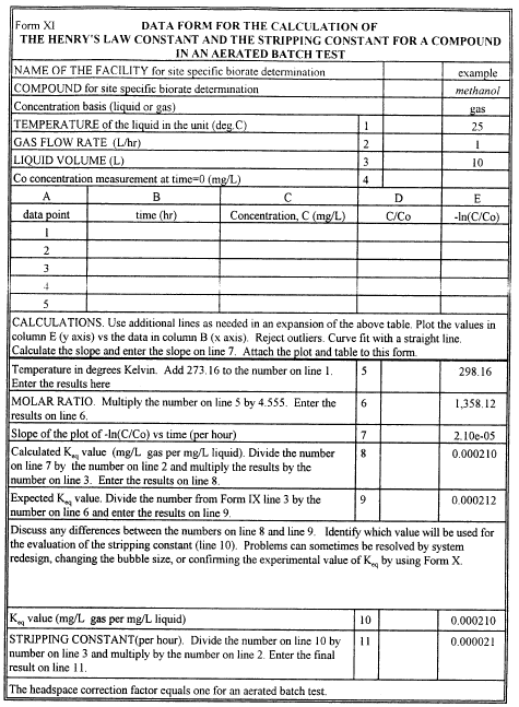
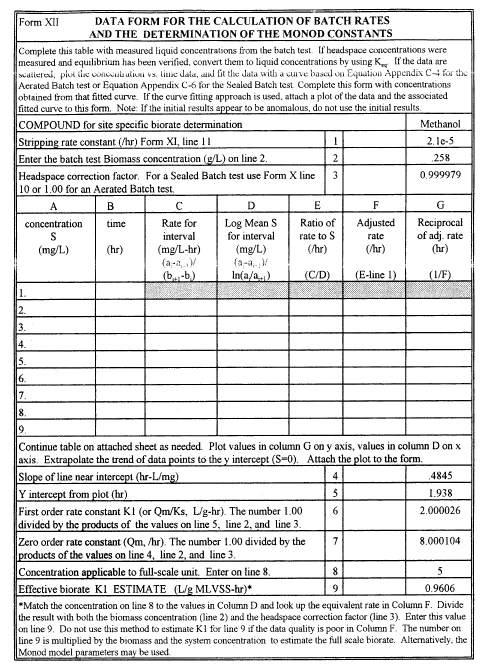
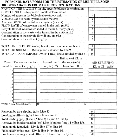
[62 FR 2801, Jan.
17, 1997, as amended at 63 FR 67794, Dec. 9, 1998; 66 FR 6935, Jan.
22, 2001]


 [62 FR 2801, Jan.
17, 1997, as amended at 63 FR 67794, Dec. 9, 1998; 66 FR 6935, Jan.
22, 2001]
 Where:
Cstd = PM concentration at standard conditions Ca = PM
concentration at measurement conditions Ts = Stack Temperature (
°F) TCEMS = CEMS Measurement Temperature ( °F) PCEMS = CEMS
Measurement Pressure (in. Hg) Ps = Stack Pressure (in. Hg) Tstd =
Standard Temperature (68 °F) Pstd = Standard Pressure (29.92 in.
Hg). 6.2.2 Heat Input-Based PM Emission Rates (Existing EGUs,
Only). Calculate the hourly heat input-based PM emission rates (if
applicable), in units of lb/MMBtu, according to sections 6.2.2.1
and 6.2.2.2 of this appendix. 6.2.2.1 You must select an
appropriate emission rate equation from among Equations 19-1
through 19-9 in appendix A-7 to part 60 of this chapter to convert
the hourly PM concentration values from section 6.2.1 of this
appendix to units of lb/MMBtu. Note that the EPA test Method 19
equations require the pollutant concentration to be expressed in
units of lb/scf; therefore, you must first multiply the PM
concentration by 6.24 × 10⁻⁸ to convert it from mg/scm to lb/scf.
 Where:
Eheo = Hourly gross output-based PM emission rate (lb/MWh) Cstd =
PM concentration from section 6.2.1 (mg/scm), wet basis Qs =
Unadjusted stack gas volumetric flow rate (scfh, wet basis) MW =
Gross output (megawatts) 6.24 × 10−8 = Conversion factor
 Where:
Eheo = Hourly gross output-based PM emission rate (lb/MWh) Cstd =
PM concentration from section 6.2.1 (mg/scm), dry basis Qs =
Unadjusted stack gas volumetric flow rate (scfh, wet basis) MW =
Gross output (megawatts) Bws = Proportion by volume of water vapor
in the stack gas 6.24 × 10−8 = Conversion factor