Title 40
PART 63 APPENDIX
| Monitoring frequency per subpart a | Detection sensitivity level |
|---|---|
| Bi-Monthly | 60 |
| Semi-Quarterly | 85 |
| Monthly | 100 |
a When this alternative work practice is used to identify leaking equipment, the owner or operator must choose one of the monitoring frequencies listed in this table, in lieu of the monitoring frequency specified in the applicable subpart. Bi-monthly means every other month. Semi-quarterly means twice per quarter. Monthly means once per month.
Table 1 to Subpart B of Part 63 - Section 112(j) Part 2 Application Due Dates
40:11.0.1.1.1.2.5.14.2 :
Table 1 to Subpart B of Part 63 - Section 112(j) Part 2 Application Due Dates| Due date | MACT standard |
|---|---|
| 10/30/03 | Combustion Turbines. Lime Manufacturing. Site Remediation. Iron and Steel Foundries. Taconite Iron Ore Processing. Miscellaneous Organic Chemical Manufacturing (MON). 1 |
| Organic Liquids
Distribution. Primary Magnesium Refining. Metal Can (Surface Coating). Plastic Parts and Products (Surface Coating). Chlorine Production. Miscellaneous Metal Parts and Products (Surface Coating) (and Asphalt/Coal Tar Application - Metal Pipes). 2 |
|
| 4/28/04 | Industrial Boilers,
Institutional/Commercial Boilers and Process Heaters.
3 Plywood and Composite Wood Products. Reciprocating Internal Combustion Engines. 4 Auto and Light-Duty Truck (Surface Coating). |
| 11/14/05 | Industrial Boilers,
Institutional/Commercial Boilers, and Process Heaters.
5 Hydrochloric Acid Production. 6 |
1 Covers 23 source categories, see Table 2 to this subpart.
2 Two source categories.
3 Includes all sources in the three categories, Industrial Boilers, Institutional/Commercial Boilers, and Process Heaters that burn no hazardous waste.
4 Includes engines greater than 500 brake horsepower.
5 Includes all sources in the three categories, Industrial Boilers, Institutional/Commercial Boilers, and Process Heaters that burn hazardous waste.
6 Includes furnaces that produce acid from hazardous waste at sources in the category Hydrochloric Acid Production.
Table 2 to Subpart B of Part 63 - MON Source Categories
40:11.0.1.1.1.2.5.14.3 :
Table 2 to Subpart B of Part 63 - MON Source Categories Manufacture of Paints, Coatings, and Adhesives. Alkyd Resins Production. Maleic Anhydride Copolymers Production. Polyester Resins Production. Polymerized Vinylidene Chloride Production. Polymethyl Methacrylate Resins Production. Polyvinyl Acetate Emulsions Production. Polyvinyl Alcohol Production. Polyvinyl Butyral Production. Ammonium Sulfate Production-Caprolactam By-Product Plants. Quaternary Ammonium Compounds Production. Benzyltrimethylammonium Chloride Production. Carbonyl Sulfide Production. Chelating Agents Production. Chlorinated Paraffins Production. Ethylidene Norbornene Production. Explosives Production. Hydrazine Production. OBPA/1,3-Diisocyanate Production. Photographic Chemicals Production. Phthalate Plasticizers Production. Rubber Chemicals Manufacturing. Symmetrical Tetrachloropyridine Production. [68 FR 32603, May 30, 2003]Table 1 to Subpart F of Part 63 - Synthetic Organic Chemical Manufacturing Industry Chemicals
40:11.0.1.1.1.6.5.9.4 :
Table 1 to Subpart F of Part 63 - Synthetic Organic Chemical Manufacturing Industry Chemicals| Chemical name a | CAS No. b | Group |
|---|---|---|
| Acenaphthene | 83329 | V |
| Acetal | 105577 | V |
| Acetaldehyde | 75070 | II |
| Acetamide | 60355 | II |
| Acetanilide | 103844 | II |
| Acetic acid | 64197 | II |
| Acetic anhydride | 108247 | II |
| Acetoacetanilide | 102012 | III |
| Acetone | 67641 | I |
| Acetone cyanohydrin | 75865 | V |
| Acetonitrile | 75058 | I |
| Acetophenone | 98862 | I |
| Acrolein | 107028 | IV |
| Acrylamide | 79061 | I |
| Acrylic acid | 79107 | IV |
| Acrylonitrile | 107131 | I |
| Adiponitrile | 111693 | I |
| Alizarin | 72480 | V |
| Alkyl anthraquinones | 008 | V |
| Allyl alcohol | 107186 | I |
| Allyl chloride | 107051 | IV |
| Allyl cyanide | 109751 | IV |
| Aminophenol sulfonic acid | 0010 | V |
| Aminophenol (p-) | 123308 | I |
| Aniline | 62533 | I |
| Aniline hydrochloride | 142041 | III |
| Anisidine (o-) | 90040 | II |
| Anthracene | 120127 | V |
| Anthraquinone | 84651 | III |
| Azobenzene | 103333 | I |
| Benzaldehyde | 100527 | III |
| Benzene | 71432 | I |
| Benzenedisulfonic acid | 98486 | I |
| Benzenesulfonic acid | 98113 | I |
| Benzil | 134816 | III |
| Benzilic acid | 76937 | III |
| Benzoic acid | 65850 | III |
| Benzoin | 119539 | III |
| Benzonitrile | 100470 | III |
| Benzophenone | 119619 | I |
| Benzotrichloride | 98077 | III |
| Benzoyl chloride | 98884 | III |
| Benzyl acetate | 140114 | III |
| Benzyl alcohol | 100516 | III |
| Benzyl benzoate | 120514 | III |
| Benzyl chloride | 100447 | III |
| Benzyl dichloride | 98873 | III |
| Biphenyl | 92524 | I |
| Bisphenol A | 80057 | III |
| Bis(Chloromethyl) Ether | 542881 | I |
| Bromobenzene | 108861 | I |
| Bromoform | 75252 | V |
| Bromonaphthalene | 27497514 | IV |
| Butadiene (1,3-) | 106990 | II |
| Butanediol (1,4-) | 110634 | I |
| Butyl acrylate (n-) | 141322 | V |
| Butylene glycol (1,3-) | 107880 | II |
| Butyrolactone | 96480 | I |
| Caprolactam | 105602 | II |
| Carbaryl | 63252 | V |
| Carbazole | 86748 | V |
| Carbon disulfide | 75150 | IV |
| Carbon tetrabromide | 558134 | II |
| Carbon tetrachloride | 56235 | I |
| Carbon tetrafluoride | 75730 | II |
| Chloral | 75876 | II |
| Chloroacetic acid | 79118 | II |
| Chloroacetophenone (2-) | 532274 | I |
| Chloroaniline (p-) | 106478 | II |
| Chlorobenzene | 108907 | I |
| 2-Chloro-1,3-butadiene (Chloroprene) | 126998 | II |
| Chlorodifluoroethane | 25497294 | V |
| Chlorodifluoromethane | 75456 | I |
| Chloroform | 67663 | I |
| Chloronaphthalene | 25586430 | IV |
| Chloronitrobenzene | 121733 | I |
| (m-). | ||
| Chloronitrobenzene | 88733 | I |
| (o-). | ||
| Chloronitrobenzene | 100005 | I |
| (p-). | ||
| Chlorophenol (m-) | 108430 | II |
| Chlorophenol (o-) | 95578 | II |
| Chlorophenol (p-) | 106489 | II |
| Chlorotoluene (m-) | 108418 | III |
| Chlorotoluene (o-) | 95498 | III |
| Chlorotoluene (p-) | 106434 | III |
| Chlorotrifluoromethane | 75729 | II |
| Chrysene | 218019 | V |
| Cresol and cresylic acid (m-) | 108394 | III |
| Cresol and cresylic acid (o-) | 95487 | III |
| Cresol and cresylic acid (p-) | 106445 | III |
| Cresols and cresylic acids (mixed) | 1319773 | III |
| Cumene | 98828 | I |
| Cumene hydroperoxide | 80159 | I |
| Cyanoacetic acid | 372098 | II |
| Cyclohexane | 110827 | I |
| Cyclohexanol | 108930 | I |
| Cyclohexanone | 108941 | I |
| Cyclohexylamine | 108918 | III |
| Cyclooctadienes | 29965977 | II |
| Decahydronaphthalene | 91178 | IV |
| Diacetoxy-2-Butene (1,4-) | 0012 | V |
| Diaminophenol hydrochloride | 137097 | V |
| Dibromomethane | 74953 | V |
| Dichloroaniline (mixed isomers) | 27134276 | I |
| Dichlorobenzene (p-) | 106467 | I |
| Dichlorobenzene (m-) | 541731 | I |
| Dichlorobenzene (o-) | 95501 | I |
| Dichlorobenzidine | 91941 | I |
| (3,3′-). | ||
| Dichlorodifluoromethane | 75718 | I |
| Dichloroethane (1,2-) (Ethylenedichloride) (EDC) | 107062 | I |
| Dichloroethyl ether (bis(2-chloroethyl)ether) | 111444 | I |
| Dichloroethylene (1,2-) | 540590 | II |
| Dichlorophenol (2,4-) | 120832 | III |
| Dichloropropene (1,3-) | 542756 | II |
| Dichlorotetrafluoro- | 1320372 | V |
| ethane. | ||
| Dichloro-1-butene (3,4-) | 760236 | II |
| Dichloro-2-butene (1,4-) | 764410 | V |
| Diethanolamine (2,2′-Iminodiethanol) | 111422 | I |
| Diethyl sulfate | 64675 | II |
| Diethylamine | 109897 | IV |
| Diethylaniline (2,6-) | 579668 | V |
| Diethylene glycol | 111466 | I |
| Diethylene glycol dibutyl ether | 112732 | I |
| Diethylene glycol diethyl ether | 112367 | I |
| Diethylene glycol dimethyl ether | 111966 | I |
| Diethylene glycol monobutyl ether acetate | 124174 | I |
| Diethylene glycol monobutyl ether | 112345 | I |
| Diethylene glycol monoethyl ether acetate | 112152 | I |
| Diethylene glycol monoethyl ether | 111900 | I |
| Diethylene glycol monohexyl ether | 112594 | V |
| Diethylene glycol monomethyl ether acetate | 629389 | V |
| Diethylene glycol monomethyl ether | 111773 | I |
| Dihydroxybenzoic acid (Resorcylic acid) | 27138574 | V |
| Dimethylbenzidine | 119937 | II |
| (3,3′-). | ||
| Dimethyl ether | 115106 | IV |
| Dimethylformamide (N,N-) | 68122 | II |
| Dimethylhydrazine | 57147 | II |
| (1,1-). | ||
| Dimethyl sulfate | 77781 | I |
| Dimethyl terephthalate | 120616 | II |
| Dimethylamine | 124403 | IV |
| Dimethylaminoethanol (2-) | 108010 | I |
| Dimethylaniline (N,N′) | 121697 | III |
| Dinitrobenzenes (NOS) c | 25154545 | I |
| Dinitrophenol (2,4-) | 51285 | III |
| Dinitrotoluene (2,4-) | 121142 | III |
| Dioxane (1,4-) (1,4-Diethyleneoxide) | 1239 | 11I |
| Dioxolane (1,3-) | 646060 | I |
| Diphenyl methane | 101815 | I |
| Diphenyl oxide | 101848 | I |
| Diphenyl thiourea | 102089 | III |
| Diphenylamine | 122394 | III |
| Dipropylene glycol | 110985 | I |
| Di-o-tolyguanidine | 97392 | III |
| Dodecanedioic acid | 693232 | I |
| Dodecyl benzene (branched) | 123013 | V |
| Dodecyl phenol (branched) | 121158585 | V |
| Dodecylaniline | 28675174 | V |
| Dodecylbenzene (n-) | 121013 | I |
| Dodecylphenol | 27193868 | III |
| Epichlorohydrin (1-chloro-2,3-epoxypropane) | 106898 | I |
| Ethanolamine | 141435 | I |
| Ethyl acrylate | 140885 | II |
| Ethylbenzene | 100414 | I |
| Ethyl chloride (Chloroethane) | 75003 | IV |
| Ethyl chloroacetate | 105395 | II |
| Ethylamine | 75047 | V |
| Ethylaniline (N-) | 103695 | III |
| Ethylaniline (o-) | 578541 | III |
| Ethylcellulose | 9004573 | V |
| Ethylcyanoacetate | 105566 | V |
| Ethylene carbonate | 96491 | I |
| Ethylene dibromide (Dibromoethane) | 106934 | I |
| Ethylene glycol | 107211 | I |
| Ethylene glycol diacetate | 111557 | I |
| Ethylene glycol dibutyl ether | 112481 | V |
| Ethylene glycol diethyl ether | 629141 | I |
| (1,2-diethoxyethane). | ||
| Ethylene glycol | 110714 | I |
| dimethyl ether | ||
| Ethylene glycol monoacetate | 542596 | V |
| Ethylene glycol monobutyl ether | 112072 | I |
| acetate. | ||
| Ethylene glycol monobutyl ether | 111762 | I |
| Ethylene glycol monoethyl ether | 111159 | I |
| acetate. | ||
| Ethylene glycol monoethyl ether | 110805 | I |
| Ethylene glycol monohexyl ether | 112254 | V |
| Ethylene glycol monomethyl ether acetate | 110496 | I |
| Ethylene glycol monomethyl ether | 109864 | I |
| Ethylene glycol monooctyl ether | 002 | V |
| Ethylene glycol monophenyl ether | 122996 | I |
| Ethylene glycol monopropyl ether | 2807309 | I |
| Ethylene oxide | 75218 | I |
| Ethylenediamine | 107153 | II |
| Ethylenediamine tetraacetic acid | 60004 | V |
| Ethylenimine (Aziridine) | 151564 | II |
| Ethylhexyl acrylate (2-isomer) | 103117 | II |
| Fluoranthene | 206440 | V |
| Formaldehyde | 50000 | I |
| Formamide | 75127 | II |
| Formic acid | 64186 | II |
| Fumaric acid | 110178 | I |
| Glutaraldehyde | 111308 | IV |
| Glyceraldehyde | 367475 | V |
| Glycerol | 56815 | II |
| Glycine | 56406 | II |
| Glyoxal | 107222 | II |
| Hexachlorobenzene | 118741 | II |
| Hexachlorobutadiene | 87683 | II |
| Hexachloroethane | 67721 | II |
| Hexadiene (1,4-) | 592450 | II |
| Hexamethylene- | 100970 | I |
| tetramine. | ||
| Hexane | 110543 | V |
| Hexanetriol (1,2,6-) | 106694 | IV |
| Hydroquinone | 123319 | I |
| Hydroxyadipaldehyde | 141311 | V |
| Isobutyl acrylate | 106638 | V |
| Isobutylene | 115117 | V |
| Isophorone | 78591 | IV |
| Isophorone nitrile | 0017 | V |
| Isophthalic acid | 121915 | III |
| Isopropylphenol | 25168063 | III |
| Linear alkylbenzene | __ d | I |
| Maleic anhydride | 108316 | I |
| Maleic hydrazide | 123331 | I |
| Malic acid | 6915157 | I |
| Metanilic acid | 121471 | I |
| Methacrylic acid | 79414 | V |
| Methanol | 67561 | IV |
| Methionine | 63683 | I |
| Methyl acetate | 79209 | IV |
| Methyl acrylate | 96333 | V |
| Methyl bromide (Bromomethane) | 74839 | IV |
| Methyl chloride (Chloromethane) | 74873 | IV |
| Methyl ethyl ketone (2-butanone) | 78933 | V |
| Methyl formate | 107313 | II |
| Methyl hydrazine | 60344 | IV |
| Methyl isobutyl carbinol | 108112 | IV |
| Methyl isobutyl ketone (Hexone) | 108101 | IV |
| Methyl isocyanate | 624839 | IV |
| Methyl mercaptan | 74931 | IV |
| Methyl methacrylate | 80626 | IV |
| Methyl phenyl carbinol | 98851 | II |
| Methyl tert-butyl ether | 1634044 | V |
| Methylamine | 74895 | IV |
| Methylaniline (N-) | 100618 | III |
| Methylcyclohexane | 108872 | III |
| Methylcyclohexanol | 25639423 | V |
| Methylcyclohexanone | 1331222 | III |
| Methylene chloride (Dichloromethane) | 75092 | I |
| Methylene dianiline (4,4′-isomer) | 101779 | I |
| Methylene diphenyl diisocyanate (4,4′-) (MDI) | 101688 | III |
| Methylionones (a-) | 79696 | V |
| Methylpentynol | 77758 | V |
| Methylstyrene (a-) | 98839 | I |
| Naphthalene | 91203 | IV |
| Naphthalene sulfonic acid (a-) | 85472 | IV |
| Naphthalene sulfonic acid (b-) | 120183 | IV |
| Naphthol (a-) | 90153 | IV |
| Naphthol (b-) | 135193 | IV |
| Naphtholsulfonic acid (1-) | 567180 | V |
| Naphthylamine sulfonic acid (1,4-) | 84866 | V |
| Naphthylamine sulfonic acid (2,1-) | 81163 | V |
| Naphthylamine (1-) | 134327 | V |
| Naphthylamine (2-) | 91598 | V |
| Nitroaniline (m-) | 99092 | II |
| Nitroaniline (o-) | 88744 | I |
| Nitroanisole (o-) | 91236 | III |
| Nitroanisole (p-) | 100174 | III |
| Nitrobenzene | 98953 | I |
| Nitronaphthalene (1-) | 86577 | IV |
| Nitrophenol (p-) | 100027 | III |
| Nitrophenol (o-) | 88755 | III |
| Nitropropane (2-) | 79469 | II |
| Nitrotoluene (all isomers) | 1321126 | III |
| Nitrotoluene (o-) | 88722 | III |
| Nitrotoluene (m-) | 99081 | III |
| Nitrotoluene (p-) | 99990 | III |
| Nitroxylene | 25168041 | V |
| Nonylbenzene (branched) | 1081772 | V |
| Nonylphenol | 25154523 | V |
| Octene-1 | 111660 | I |
| Octylphenol | 27193288 | III |
| Paraformaldehyde | 30525894 | I |
| Paraldehyde | 123637 | II |
| Pentachlorophenol | 87865 | III |
| Pentaerythritol | 115775 | I |
| Peracetic acid | 79210 | II |
| Perchloromethyl mercaptan | 594423 | IV |
| Phenanthrene | 85018 | V |
| Phenetidine (p-) | 156434 | III |
| Phenol | 108952 | III |
| Phenolphthalein | 77098 | III |
| Phenolsulfonic acids (all isomers) | 1333397 | III |
| Phenyl anthranilic acid (all isomers) | 91407 | III |
| Phenylenediamine (p-) | 106503 | I |
| Phloroglucinol | 108736 | III |
| Phosgene | 75445 | IV |
| Phthalic acid | 88993 | III |
| Phthalic anhydride | 85449 | III |
| Phthalimide | 85416 | III |
| Phthalonitrile | 91156 | III |
| Picoline (b-) | 108996 | II |
| Piperazine | 110850 | I |
| Propiolactone (beta-) | 57578 | I |
| Propionaldehyde | 123386 | IV |
| Propionic acid | 79094 | I |
| Propylene carbonate | 108327 | V |
| Propylene dichloride (1,2-dichloropropane) | 78875 | IV |
| Propylene glycol | 57556 | I |
| Propylene glycol monomethyl ether | 107982 | I |
| Propylene oxide | 75569 | I |
| Pyrene | 129000 | V |
| Pyridine | 110861 | II |
| p-tert-Butyl toluene | 98511 | III |
| Quinone | 106514 | III |
| Resorcinol | 108463 | I |
| Salicylic acid | 69727 | III |
| Sodium methoxide | 124414 | IV |
| Sodium phenate | 139026 | III |
| Stilbene | 588590 | III |
| Styrene | 100425 | I |
| Succinic acid | 110156 | I |
| Succinonitrile | 110612 | I |
| Sulfanilic acid | 121573 | III |
| Sulfolane | 126330 | II |
| Tartaric acid | 526830 | I |
| Terephthalic acid | 100210 | II |
| Tetrabromophthalic anhydride | 632791 | III |
| Tetrachlorobenzene (1,2,4,5-) | 95943 | I |
| Tetrachloroethane (1,1,2,2-) | 79345 | II |
| Tetrachloroethylene (Perchloroethylene) | 127184 | I |
| Tetrachlorophthalic- | 117088 | III |
| anhydride. | ||
| Tetraethyl lead | 78002 | IV |
| Tetraethylene glycol | 112607 | I |
| Tetraethylene- | 112572 | V |
| pentamine. | ||
| Tetrahydrofuran | 109999 | I |
| Tetrahydronapthalene | 119642 | IV |
| Tetrahydrophthalic anhydride | 85438 | II |
| Tetramethylene- | 110601 | II |
| diamine. | ||
| Tetramethylethylenediamine | 110189 | V |
| Tetramethyllead | 75741 | V |
| Toluene | 108883 | I |
| Toluene 2,4 diamine | 95807 | II |
| Toluene 2,4 diisocyanate | 584849 | II |
| Toluene diisocyanates (mixture) | 26471625 | II |
| Toluene sulfonic acids | 104154 | III |
| Toluenesulfonyl chloride | 98599 | III |
| Toluidine (o-) | 95534 | II |
| Trichloroaniline- | 634935 | III |
| (2,4,6-). | ||
| Trichlorobenzene (1,2,3-) | 87616 | V |
| Trichlorobenzene (1,2,4-) | 120821 | I |
| Trichloroethane | 71556 | II |
| (1,1,1-) | ||
| Trichloroethane (1,1,2-) (Vinyl trichloride) | 79005 | II |
| Trichloroethylene | 79016 | I |
| Trichlorofluoromethane | 75694 | I |
| Trichlorophenol | 95954 | I |
| (2,4,5-). | ||
| (1,1,2-) Trichloro | 76131 | I |
| (1,2,2-) trifluoroethane. | ||
| Triethanolamine | 102716 | I |
| Triethylamine | 121448 | IV |
| Triethylene glycol | 112276 | I |
| Triethylene glycol | 112492 | I |
| dimethyl ether. | ||
| Triethylene glycol monoethyl ether | 112505 | V |
| Triethylene glycol monomethyl ether | 112356 | I |
| Trimethylamine | 75503 | IV |
| Trimethylcyclohexanol | 933482 | IV |
| Trimethylcyclo- | 2408379 | IV |
| hexanone. | ||
| Trimethylcyclo- | 34216347 | V |
| hexylamine. | ||
| Trimethylolpropane | 77996 | I |
| Trimethylpentane (2,2,4-) | 540841 | V |
| Tripropylene glycol | 24800440 | V |
| Vinyl acetate | 108054 | II |
| Vinyl chloride (Chloroethylene) | 75014 | I |
| Vinyl toluene | 25013154 | III |
| Vinylcyclohexene (4-) | 100403 | II |
| Vinylidene chloride | 75354 | II |
| (1,1-dichloroethylene). | ||
| Vinyl(N-)-pyrrolidone(2-) | 88120 | V |
| Xanthates | 140896 | V |
| Xylene sulfonic acid | 25321419 | III |
| Xylenes (NOS) c | 1330207 | I |
| Xylene (m-) | 108383 | I |
| Xylene (o-) | 95476 | I |
| Xylene (p-) | 106423 | I |
| Xylenols (Mixed) | 1300716 | V |
| Xylidene | 1300738 | III |
a Isomer means all structural arrangements for the same number of atoms of each element and does not mean salts, esters, or derivatives.
b CAS Number = Chemical Abstract Service number.
c NOS = not otherwise specified.
d No CAS number assigned.
Table 2 to Subpart F of Part 63 - Organic Hazardous Air Pollutants
40:11.0.1.1.1.6.5.9.5 :
Table 2 to Subpart F of Part 63 - Organic Hazardous Air Pollutants| Chemical name a b | CAS No. c |
|---|---|
| Acenaphthene | 83329 |
| Acetaldehyde | 75070 |
| Acetamide | 60355 |
| Acetonitrile | 75058 |
| Acetophenone | 98862 |
| Acrolein | 107028 |
| Acrylamide | 79061 |
| Acrylic acid | 79107 |
| Acrylonitrile | 107131 |
| Alizarin | 72480 |
| Allyl chloride | 107051 |
| Aniline | 62533 |
| Anisidine (o-) | 90040 |
| Anthracene | 120127 |
| Anthraquinone | 84651 |
| Benzene | 71432 |
| Benzotrichloride | 98077 |
| Benzyl chloride | 100447 |
| Biphenyl | 92524 |
| Bis(chloromethyl)ether | 542881 |
| Bromoform | 75252 |
| Bromonaphthalene | 27497514 |
| Butadiene (1,3-) | 106990 |
| Carbon disulfide | 75150 |
| Carbon tetrachloride | 56235 |
| Chloroacetic acid | 79118 |
| Chloroacetophenone (2-) | 532274 |
| Chlorobenzene | 108907 |
| 2-Chloro-,1,3-butadiene (Chloroprene) | 126998 |
| Chloroform | 67663 |
| Chloronaphthalene | 25586430 |
| Chrysene | 218019 |
| Cresols and cresylic acids (mixed) | 1319773 |
| Cresol and cresylic acid (o-) | 95487 |
| Cresol and cresylic acid (m-) | 108394 |
| Cresol and cresylic acid (p-) | 106445 |
| Cumene | 98828 |
| Dichlorobenzene (p-) | 106467 |
| Dichlorobenzidine (3,3′-) | 91941 |
| Dichloroethane (1,2-) (Ethylene dichloride) (EDC) | 107062 |
| Dichloroethylether (Bis(2-chloroethyl)ether) | 111444 |
| Dichloropropene (1,3-) | 542756 |
| Diethanolamine (2,2′-Iminodiethanol) | 111422 |
| Dimethylaniline (N,N-) | 121697 |
| Diethyl sulfate | 64675 |
| Dimethylbenzidine (3,3′-) | 119937 |
| Dimethylformamide (N,N-) | 68122 |
| Dimethylhydrazine (1,1-) | 58147 |
| Dimethylphthalate | 131113 |
| Dimethylsulfate | 77781 |
| Dinitrophenol (2,4-) | 51285 |
| Dinitrotoluene (2,4-) | 121142 |
| Dioxane (1,4-) (1,4-Diethyleneoxide) | 123911 |
| 1,2-Diphenylhydrazine | 122667 |
| Epichlorohydrin (1-Chloro-2,3-epoxypropane) | 106898 |
| Ethyl acrylate | 140885 |
| Ethylbenzene | 100414 |
| Ethyl chloride (Chloroethane) | 75003 |
| Ethylene dibromide (Dibromoethane) | 106934 |
| Ethylene glycol | 107211 |
| Ethylene oxide | 75218 |
| Ethylidene dichloride (1,1-Dichloroethane) | 75343 |
| Fluoranthene | 206440 |
| Formaldehyde | 50000 |
| Glycol ethers d | |
| Hexachlorobenzene | 118741 |
| Hexachlorobutadiene | 87683 |
| Hexachloroethane | 67721 |
| Hexane | 110543 |
| Hydroquinone | 123319 |
| Isophorone | 78591 |
| Maleic anhydride | 108316 |
| Methanol | 67561 |
| Methylbromide (Bromomethane) | 74839 |
| Methylchloride (Chloromethane) | 74873 |
| Methyl hydrazine | 60344 |
| Methyl isobutyl ketone (Hexone) | 108101 |
| Methyl isocyanate | 624839 |
| Methyl methacrylate | 80626 |
| Methyl tert-butyl ether | 1634044 |
| Methylene chloride (Dichloromethane) | 75092 |
| Methylene diphenyl diisocyanate (4,4′-) (MDI) | 101688 |
| Methylenedianiline (4,4′-) | 101779 |
| Naphthalene | 91203 |
| Naphthalene sulfonic acid (α) | 85472 |
| Naphthalene sulfonic acid (β) | 120183 |
| Naphthol (α) | 90153 |
| Naphthol (β) | 135193 |
| Naphtholsulfonic acid (1-) | 567180 |
| Naphthylamine sulfonic acid (1,4-) | 84866 |
| Naphthylamine sulfonic acid (2,1-) | 81163 |
| Naphthylamine (1-) | 134327 |
| Naphthylamine (2-) | 91598 |
| Nitronaphthalene (1-) | 86577 |
| Nitrobenzene | 98953 |
| Nitrophenol (p-) | 100027 |
| Nitropropane (2-) | 79469 |
| Phenanthrene | 85018 |
| Phenol | 108952 |
| Phenylenediamine (p-) | 106503 |
| Phosgene | 75445 |
| Phthalic anhydride | 85449 |
| Propiolactone (beta-) | 57578 |
| Propionaldehyde | 123386 |
| Propylene dichloride (1,2-Dichloropropane) | 78875 |
| Propylene oxide | 75569 |
| Pyrene | 129000 |
| Quinone | 106514 |
| Styrene | 100425 |
| Tetrachloroethane (1,1,2,2-) | 79345 |
| Tetrachloroethylene (Perchloroethylene) | 127184 |
| Tetrahydronaphthalene | 119642 |
| Toluene | 108883 |
| Toluene diamine (2,4-) | 95807 |
| Toluene diisocyanate (2,4-) | 584849 |
| Toluidine (o-) | 95534 |
| Trichlorobenzene (1,2,4-) | 120821 |
| Trichloroethane (1,1,1-) (Methyl chloroform) | 71556 |
| Trichloroethane (1,1,2-) (Vinyl trichloride) | 79005 |
| Trichloroethylene | 79016 |
| Trichlorophenol (2,4,5-) | 95954 |
| Triethylamine | 121448 |
| Trimethylpentane (2,2,4-) | 540841 |
| Vinyl acetate | 108054 |
| Vinyl chloride (Chloroethylene) | 75014 |
| Vinylidene chloride (1,1-Dichloroethylene) | 75354 |
| Xylenes (NOS) | 1330207 |
| Xylene (m-) | 108383 |
| Xylene (o-) | 95476 |
| Xylene (p-) | 106423 |
a For all Listings above containing the word “Compounds,” the following applies: Unless otherwise specified, these listings are defined as including any unique chemical substance that contains the named chemical (i.e., antimony, arsenic) as part of that chemical's infrastructure.
b Isomer means all structural arrangements for the same number of atoms of each element and does not mean salts, esters, or derivatives.
c CAS No. = Chemical Abstract Service number.
d Includes mono- and di- ethers of ethylene glycol, diethylene glycol, and triethylene glycol R-(OCH2 CH2n-OR where:
n = 1, 2, or 3;
R = alkyl or aryl groups; and
R″ = R, H or groups which, when removed, yield glycol ethers with the structure:
R-(OCH2 CH2n-OH
Polymers are excluded from the glycol category.
Table 3 to Subpart F of Part 63 - General Provisions Applicability to Subparts F, G, and H a to Subpart F
40:11.0.1.1.1.6.5.9.6 :
Table 3 to Subpart F of Part 63 - General Provisions Applicability to Subparts F, G, and H a to Subpart F| Reference | Applies to subparts F, G, and H | Comment |
|---|---|---|
| 63.1(a)(1) | Yes | Overlap clarified in § 63.101, § 63.111, § 63.161. |
| 63.1(a)(2) | Yes | |
| 63.1(a)(3) | Yes | § 63.110 and § 63.160(b) of subparts G and H identify which standards are overridden. |
| 63.1(a)(4) | No | Subpart F specifies applicability of each paragraph in subpart A to subparts F, G, and H. |
| 63.1 (a)(5)-(a)(9) | No | |
| 63.1(a)(10) | No | Subparts F, G, and H specify calendar or operating day. |
| 63.1(a)(11) | No | Subpart F § 63.103(d) specifies acceptable methods for submitting reports. a |
| 63.1 (a)(12)-(a)(14) | Yes | |
| 63.1(b)(1) | No | Subpart F specifies applicability. |
| 63.1(b)(2) | Yes | |
| 63.1(b)(3) | No | |
| 63.1(c)(1) | No | Subpart F specifies applicability. |
| 63.1(c)(2) | No | Area sources are not subject to subparts F, G, and H. |
| 63.1(c)(3) | No | |
| 63.1(c)(4) | Yes | |
| 63.1(c)(5) | No | Subparts G and H specify applicable notification requirements. |
| 63.1(c)(6) | Yes | |
| 63.1(d) | No | |
| 63.1(e) | No | Subparts F, G, and H established before permit program. |
| 63.2 | Yes | Subpart F § 63.101(a) specifies those subpart A definitions that apply to the HON. Subpart F definition of “source” is equivalent to subpart A definition of “affected source.” |
| 63.3 | No | Units of measure are spelled out in subparts F, G, and H. |
| 63.4 (a)(1)-(a)(3) | Yes | |
| 63.4(a)(4) | No | This is a reserved paragraph in subpart A of part 63. |
| 63.4(a)(5) | Yes | |
| 63.4(b) | Yes | |
| 63.4(c) | Yes | |
| 63.5(a)(1) | Yes | Except the terms “source” and “stationary source” in § 63.5(a)(1) should be interpreted as having the same meaning as “affected source.” |
| 63.5(a)(2) | Yes | |
| 63.5(b)(1) | Yes | Except § 63.100(l) defines when construction or reconstruction is subject to standards for new sources. |
| 63.5(b)(2) | No | This is a reserved paragraph in subpart A of part 63. |
| 63.5(b)(3) | Yes | |
| 63.5(b)(4) | Yes | Except the cross reference to § 63.9(b) is limited to § 63.9(b) (4) and (5). Subpart F overrides § 63.9 (b)(1) through (b)(3). |
| 63.5(b)(5) | Yes | |
| 63.5(b)(6) | Yes | Except § 63.100(l) defines when construction or reconstruction is subject to standards for new sources. |
| 63.5(c) | No | This is a reserved paragraph in subpart A of part 63. |
| 63.5(d)(1)(i) | No | For subpart G, see § 63.151(b) (2)(ii) and (2)(iii) for the applicability and timing of this submittal; for subpart H, see § 63.182(b) (2)(ii) and (b)(2)(iii) for applicability and timing of this submittal. |
| 63.5(d)(1)(ii) | Yes | Except § 63.5(d)(1)(ii)(H) does not apply. |
| 63.5(d)(1)(iii) | No | Subpart G requires submittal of the Notification of Compliance Status in § 63.152(b); subpart H specifies requirements in § 63.182(c). |
| 63.5(d)(2) | No | |
| 63.5(d)(3) | Yes - subpart G No - subpart H | Except § 63.5(d)(3)(ii) does not apply to subpart G. |
| 63.5(d)(4) | Yes | |
| 63.5(e) | Yes | |
| 63.5(f)(1) | Yes | |
| 63.5(f)(2) | Yes | Except the cross-reference to § 63.5(d)(1) is changed to § 63.151(b)(2)(ii) of subpart G and to § 63.182(b)(2)(ii) of subpart H. The cross-reference to § 63.5(b)(2) does not apply. |
| 63.6(a) | Yes | |
| 63.6(b)(1) | No | Subparts F and H specify compliance dates for sources subject to subparts F, G, and H. |
| 63.6(b)(2) | No | |
| 63.6(b)(3) | Yes | |
| 63.6(b)(4) | No | May apply when standards are proposed under Section 112(f) of the Clean Air Act. |
| 63.6(b)(5) | No | Subparts G and H include notification requirements. |
| 63.6(b)(6) | No | |
| 63.6(b)(7) | No | |
| 63.6(c)(1) | No | Subpart F specifies the compliance dates for subparts G and H. |
| 63.6(c)(2) | No | |
| 63.6(c)(3) | No | |
| 63.6(c)(4) | No | |
| 63.6(c)(5) | Yes | |
| 63.6(d) | No | |
| 63.6(e) | Yes | Except as otherwise specified for individual paragraphs. Does not apply to Group 2 emission points unless they are included in an emissions average. b |
| 63.6(e)(1)(i) | No | This is addressed by § 63.102(a)(4) of subpart F. |
| 63.6(e)(1)(ii) | Yes | |
| 63.6(e)(1)(iii) | Yes | |
| 63.6(e)(2) | Yes | |
| 63.6(e)(3)(i) | Yes | For subpart H, the startup, shutdown, and malfunction plan requirement of § 63.6(e)(3)(i) is limited to control devices subject to the provisions of subpart H and is optional for other equipment subject to subpart H. The startup, shutdown, and malfunction plan may include written procedures that identify conditions that justify a delay of repair. |
| 63.6(e)(3)(i)(A) | No | This is addressed by § 63.102(a)(4). |
| 63.6(e)(3)(i)(B) | Yes | |
| 63.6(e)(3)(i)(C) | Yes | |
| 63.6(e)(3)(ii) | Yes | |
| 63.6(e)(3)(iii) | No | Recordkeeping and reporting are specified in § 63.103(c)(2) of subpart F and § 63.152(d)(1) of subpart G. |
| 63.6(e)(3)(iv) | No | Recordkeeping and reporting are specified in § 63.103(c)(2) of subpart F and § 63.152(d)(1) of subpart G. |
| 63.6(e)(3)(v) | No | Records retention requirements are specified in § 63.103(c). |
| 63.6(e)(3)(vi) | Yes | |
| 63.6(e)(3)(vii) | Yes | |
| 63.6(e)(3)(vii)(A) | Yes | |
| 63.6(e)(3)(vii)(B) | Yes | Except the plan must provide for operation in compliance with § 63.102(a)(4). |
| 63.6(e)(3)(vii)(C) | Yes | |
| 63.6(e)(3)(viii) | Yes | |
| 63.6(e)(3)(ix) | Yes | |
| 63.6(f)(1) | No | § 63.102(a) of subpart F specifies when the standards apply. |
| 63.6(f)(2)(i) | Yes | |
| 63.6(f)(2)(ii) | Yes - subpart G No - subpart H | § 63.152(c)(2) of subpart G specifies the use of monitoring data in determining compliance with subpart G. |
| 63.6(f)(2)(iii) (A), (B), and (C) | Yes | |
| 63.6(f)(2)(iii)(D) | No | |
| 63.6(f)(2)(iv) | Yes | |
| 63.6(f)(2)(v) | Yes | |
| 63.6(f)(3) | Yes | |
| 63.6(g) | No | Procedures specified in § 63.102(b) of subpart F. |
| 63.6(h) | No | |
| 63.6(i)(1) | Yes | |
| 63.6(i)(2) | Yes | |
| 63.6(i)(3) | No | For subpart G, § 63.151(a)(6) specifies procedures; for subpart H, § 63.182(a)(6) specifies procedures. |
| 63.6(i)(4)(i)(A) | Yes | |
| 63.6(i)(4)(i)(B) | No | Dates are specified in § 63.151(a)(6)(i) of subpart G and § 63.182(a)(6)(i) of subpart H. |
| 63.6(i)(4)(ii) | No | |
| 63.6(i) (5)-(14) | Yes | |
| 63.6(i)(15) | No | |
| 63.6(i)(16) | Yes | |
| 63.6(j) | Yes | |
| 63.7(a)(1) | No | Subparts F, G, and H specify required testing and compliance demonstration procedures. |
| 63.7(a)(2) | No | For subpart G, test results must be submitted in the Notification of Compliance Status due 150 days after compliance date, as specified in § 63.152(b); for subpart H, all test results subject to reporting are reported in periodic reports. |
| 63.7(a)(3) | Yes | |
| 63.7(b) | No | |
| 63.7(c) | No | |
| 63.7(d) | Yes | |
| 63.7(e)(1) | Yes | |
| 63.7(e)(2) | Yes | |
| 63.7(e)(3) | No | Subparts F, G, and H specify test methods and procedures. |
| 63.7(e)(4) | Yes | |
| 63.7(f) | No | Subparts F, G, and H specify applicable methods and provide alternatives. |
| 63.7(g) | No | Performance test reporting specified in § 63.152(b) of subpart G: Not applicable to subpart H because no performance test required by subpart H. |
| 63.7(h)(1) | Yes | |
| 63.7(h)(2) | Yes | |
| 63.7(h)(3) | No | § 63.103(b)(5) of subpart F specifies provisions for requests to waive performance tests. |
| 63.7(h)(4) | No | |
| 63.7(h)(5) | Yes | |
| 63.8(a)(1) | Yes | |
| 63.8(a)(2) | No | |
| 63.8(a)(3) | No | |
| 63.8(a)(4) | Yes | |
| 63.8(b)(1) | Yes | |
| 63.8(b)(2) | No | Subparts G and H specify locations to conduct monitoring. |
| 63.8(b)(3) | Yes | |
| 63.8(c)(1)(i) | Yes | |
| 63.8(c)(1)(ii) | No | For subpart G, submit as part of periodic report required by § 63.152(c); for subpart H, retain as required by § 63.181(g)(2)(ii). |
| 63.8(c)(1)(iii) | Yes | |
| 63.8(c)(2) | Yes | |
| 63.8(c)(3) | Yes | |
| 63.8(c)(4) | No | Subpart G specifies monitoring frequency by kind of emission point and control technology used (e.g., § 63.111, § 63.120(d)(2), § 63.143, and § 63.152(f)); subpart H does not require use of continuous monitoring systems. |
| 63.8 (c)(5)-(c)(8) | No | |
| 63.8(d) | No | |
| 63.8(e) | No | |
| 63.8 (f)(1)-(f)(3) | Yes | |
| 63.8(f)(4)(i) | No | Timeframe for submitting request specified in § 63.151(f) or (g) of subpart G; not applicable to subpart H because subpart H specifies acceptable alternative methods. |
| 63.8(f)(4)(ii) | Yes | |
| 63.8(f)(4)(iii) | No | |
| 63.8(f)(5)(i) | Yes | |
| 63.8(f)(5)(ii) | No | |
| 63.8(f)(5)(iii) | Yes | |
| 63.8(f)(6) | No | Subparts G and H do not require continuous emission monitoring. |
| 63.8(g) | No | Data reduction procedures specified in § 63.152(f) and (g) of subpart G; not applicable to subpart H. |
| 63.9(a) | Yes | |
| 63.9(b)(1) | No | Specified in § 63.151(b)(2) of subpart G; specified in § 63.182(b) of subpart H. |
| 63.9(b)(2) | No | Initial Notification provisions are specified in § 63.151(b) of subpart G; in § 63.182(b) of subpart H. |
| 63.9(b)(3) | No | |
| 63.9(b)(4) | Yes | Except that the notification in § 63.9(b)(4)(i) shall be submitted at the time specified in § 63.151(b)(2)(ii) of subpart G; in § 63.182(b)(2) of subpart H. |
| 63.9(b)(5) | Yes | Except that the notification in § 63.9(b)(5) shall be submitted at the time specified in § 63.151(b)(2)(ii) of subpart G; in § 63.182 (b)(2) of subpart H. |
| 63.9(c) | Yes | |
| 63.9(d) | Yes | |
| 63.9(e) | No | |
| 63.9(f) | No | |
| 63.9(g) | No | |
| 63.9(h) | No | § 63.152(b) of subpart G and § 63.182 (c) of subpart H specify Notification of Compliance Status requirements. |
| 63.9(i) | Yes | |
| 63.9(j) | Yes | Only as related to change to major source status. |
| 63.9(k) | Yes | Only as specified in § 63.9(j). |
| 63.10(a) | Yes | |
| 63.10(b)(1) | No | § 63.103(c) of subpart F specifies record retention requirements. |
| 63.10(b)(2) | No | § 63.103(c) of subpart F specifies required records. |
| 63.10(b)(3) | No | |
| 63.10(c) | No | |
| 63.10(d)(1) | No | |
| 63.10(d)(2) | No | § 63.152(b) of subpart G specifies performance test reporting; not applicable to subpart H. |
| 63.10(d)(3) | No | |
| 63.10(d)(4) | Yes | |
| 63.10(d)(5) | Yes | Except that reports required by § 63.10(d)(5) shall be submitted at the time specified in § 63.152(d) of subpart G and in § 63.182(d) of subpart H. |
| 63.10(e) | No | |
| 63.10(f) | Yes | |
| 63.11-63.15 | Yes |
a Wherever subpart A specifies “postmark” dates, submittals may be sent by methods other than the U.S. Mail (e.g., by fax or courier). Submittals shall be sent by the specified dates, but a postmark is not necessarily required.
b The plan, and any records or reports of start-up, shutdown, and malfunction do not apply to Group 2 emission points unless they are included in an emissions average.
Table 4 to Subpart F of Part 63 - Organic Hazardous Air Pollutants Subject to Cooling Tower Monitoring Requirements in § 63.104
40:11.0.1.1.1.6.5.9.7 :
Table 4 to Subpart F of Part 63 - Organic Hazardous Air Pollutants Subject to Cooling Tower Monitoring Requirements in § 63.104| Chemical name | CAS Number a |
|---|---|
| Acetaldehyde | 75070 |
| Acetonitrile | 75058 |
| Acetophenone | 98862 |
| Acrolein | 107028 |
| Acrylonitrile | 107131 |
| Allyl chloride | 107051 |
| Aniline | 62533 |
| Anisidine (o-) | 90040 |
| Benzene | 71432 |
| Benzyl chloride | 100447 |
| Biphenyl | 92524 |
| Bromoform | 75252 |
| Butadiene (1,3-) | 106990 |
| Carbon disulfide | 75150 |
| Carbon tetrachloride | 56235 |
| Chloroacetophenone (2-) | 532274 |
| Chlorobenzene | 108907 |
| 2-Chloro-1,3-butadiene (Chloroprene) | 126998 |
| Chloroform | 67663 |
| Cresol and cresylic acid (o-) | 95487 |
| Cresol and cresylic acid (m-) | 108394 |
| Cresol and cresylic acid (p-) | 106445 |
| Cumene | 98828 |
| Dichlorobenzene (p-) | 106467 |
| Dichlorobenzidine (3,3″-) | 91941 |
| Dichloroethane (1,2-) (Ethylene dichloride) (EDC) | 107062 |
| Dichloroethyl ether (Bis(2-chloroethyl)ether) | 111444 |
| Dichloropropene (1,3-) | 542756 |
| Diethylene glycol diethyl ether | 112367 |
| Diethylene glycol dimethyl ether | 111966 |
| Diethyl sulfate | 64675 |
| Dimethylaniline (N,N-) | 121697 |
| Dimethylhydrazine (1,1-) | 57147 |
| Dimethyl phthalate | 131113 |
| Dimethyl sulfate | 77781 |
| Dinitrophenol (2,4-) | 51285 |
| Dinitrotoluene (2,4-) | 121142 |
| Dioxane (1,4-) (1,4-Diethyleneoxide) | 123911 |
| Epichlorohydrin (1-Chloro-2,3-epoxypropane) | 106898 |
| Ethyl acrylate | 140885 |
| Ethylbenzene | 100414 |
| Ethyl chloride (Chloroethane) | 75003 |
| Ethylene dibromide (Dibromoethane) | 106934 |
| Ethylene glycol dimethyl ether | 110714 |
| Ethylene glycol monobutyl ether | 111762 |
| Ethylene glycol monobutyl ether acetate | 112072 |
| Ethylene glycol monoethyl ether acetate | 111159 |
| Ethylene glycol monoethyl ether | 110805 |
| Ethylene glycol monomethyl ether | 109864 |
| Ethylene glycol monomethyl ether acetate | 110496 |
| Ethylene glycol monopropyl ether | 2807309 |
| Ethylene oxide | 75218 |
| Ethylidene dichloride (1,1-Dichloroethane) | 75343 |
| Formaldehyde | 50000 |
| Hexachlorobenzene | 118741 |
| Hexachlorobutadiene | 87683 |
| Hexachloroethane | 67721 |
| Hexane | 110543 |
| Isophorone | 78591 |
| Methanol | 67561 |
| Methyl bromide (Bromomethane) | 74839 |
| Methyl chloride (Chloromethane) | 74873 |
| Methyl hydrazine | 60344 |
| Methyl isobutyl ketone (Hexone) | 108101 |
| Methyl methacrylate | 80626 |
| Methyl tert-butyl ether | 1634044 |
| Methylene chloride (Dichloromethane) | 75092 |
| Methylenedianiline (4,4″-) | 101779 |
| Naphthalene | 91203 |
| Nitrobenzene | 98953 |
| Nitropropane (2-) | 79469 |
| Phenol | 108952 |
| Phenylenediamine (p-) | 106503 |
| Phosgene | 75445 |
| Propionaldehyde | 123386 |
| Propylene dichloride (1,2-Dichloropropane) | 78875 |
| Propylene oxide | 75569 |
| Quinone | 106514 |
| Styrene | 100425 |
| Tetrachloroethane (1,1,2,2-) | 79345 |
| Tetrachloroethylene (Perchloroethylene) | 127184 |
| Toluene | 108883 |
| Toluidine (o-) | 95534 |
| Trichlorobenzene (1,2,4-) | 120821 |
| Trichloroethane (1,1,1-) (Methyl chloroform) | 71556 |
| Trichloroethane (1,1,2-) (Vinyl trichloride) | 79005 |
| Trichloroethylene | 79016 |
| Trichlorophenol (2,4,5-) | 95954 |
| Triethylamine | 121448 |
| Trimethylpentane (2,2,4-) | 540841 |
| Vinyl acetate | 108054 |
| Vinyl chloride (chloroethylene) | 75014 |
| Vinylidene chloride (1,1-Dichloroethylene) | 75354 |
| Xylene (m-) | 108383 |
| Xylene (o-) | 95476 |
| Xylene (p-) | 106423 |
a CAS Number = Chemical Abstract Service number.
Table 1 to Subpart G of Part 63 - Process Vents - Coefficients for Total Resource Effectiveness for Existing Source Nonhalogenated and Halogenated Vent Streams
40:11.0.1.1.1.7.5.43.8 :
Table 1 to Subpart G of Part 63 - Process Vents - Coefficients for Total Resource Effectiveness for Existing Source Nonhalogenated and Halogenated Vent Streams| Type of Stream | Control Device Basis | Values of Coefficients | |||
|---|---|---|---|---|---|
| a | b | c | d | ||
| Nonhalogenated | Flare | 1.935 | 3.660 × 10⁻¹ | −7.687 × 10⁻³ | −7.333 × 10⁻⁴ |
| Thermal Incinerator 0 Percent Heat Recovery | 1.492 | 6.267 × 10⁻² | 3.177 × 10⁻² | −1.159 × 10⁻³ | |
| Thermal Incinerator 70 Percent Heat Recovery | 2.519 | 1.183 × 10⁻² | 1.300 × 10⁻² | 4.790 × 10⁻² | |
| Halogenated | Thermal Incinerator and Scrubber | 3.995 | 5.200 × 10⁻² | −1.769 × 10⁻³ | 9.700 × 10⁻⁴ |
Table 1A to Subpart G of Part 63 - Applicable 40 CFR Part 63 General Provisions
40:11.0.1.1.1.7.5.43.9 :
Table 1A to Subpart G of Part 63 - Applicable 40 CFR Part 63 General Provisions| 40 CFR part 63, subpart A, provisions applicable to subpart G |
|---|
| § 63.1(a)(1), (a)(2), (a)(3), (a)(13), (a)(14), (b)(2) and (c)(4) |
| § 63.2 |
| § 63.5(a)(1), (a)(2), (b), (d)(1)(ii), (d)(3)(i), (d)(3)(iii) through (d)(3)(vi), (d)(4), (e), (f)(1), and (f)(2) |
| § 63.6(a), (b)(3), (c)(5), (i)(1), (i)(2), (i)(4)(i)(A), (i)(5) through (i)(14), (i)(16) and (j) |
| § 63.9(a)(2), (b)(4)(i), a (b)(4)(ii), (b)(4)(iii), (b)(5), a (c), (d), (j), and (k). |
| § 63.10(d)(4) |
| § 63.11 (c), (d), and (e) |
| § 63.12(b) |
a The notifications specified in § 63.9(b)(4)(i) and (b)(5) shall be submitted at the times specified in 40 CFR part 65.
Table 2 to Subpart G of Part 63 - Process Vents - Coefficients for Total Resource Effectiveness for New Source Nonhalogenated and Halogenated Vent Streams
40:11.0.1.1.1.7.5.43.10 :
Table 2 to Subpart G of Part 63 - Process Vents - Coefficients for Total Resource Effectiveness for New Source Nonhalogenated and Halogenated Vent Streams| Type of stream | Control device basis | Values of Coefficients | |||
|---|---|---|---|---|---|
| a | b | c | d | ||
| Nonhalogenated | Flare | 0.5276 | 0.0998 | −2.096 × 10⁻³ | −2.000 × 10⁻⁴ |
| Thermal Incinerator 0 Percent Heat Recovery | 0.4068 | 0.0171 | 8.664 × 10⁻³ | −3.162 × 10⁻⁴ | |
| Thermal Incinerator 70 Percent Heat Recovery | 0.6868 | 3.209 × 10⁻³ | 3.546 × 10⁻³ | 1.306 × 10⁻² | |
| Halogenated | Thermal Incinerator and Scrubber | 1.0895 | 1.417 × 10⁻² | −4.822 × 10⁻⁴ | 2.645 × 10⁻⁴ |
Table 3 to Subpart G of Part 63 - Process Vents - Monitoring, Recordkeeping, and Reporting Requirements for Complying With 98 Weight-Percent Reduction of Total Organic Hazardous Air Pollutants Emissions or a Limit of 20 Parts Per Million by Volume
40:11.0.1.1.1.7.5.43.11 :
Table 3 to Subpart G of Part 63 - Process Vents - Monitoring, Recordkeeping, and Reporting Requirements for Complying With 98 Weight-Percent Reduction of Total Organic Hazardous Air Pollutants Emissions or a Limit of 20 Parts Per Million by Volume| Control device | Parameters to be monitored a |
Recordkeeping and reporting requirements for monitored parameters |
|---|---|---|
| Thermal incinerator | Firebox temperature b [63.114(a)(1)(i)] | 1. Continuous records.
c 2. Record and report the firebox temperature averaged over the full period of the performance test - NCS. d 3. Record the daily average firebox temperature for each operating day. e 4. Report all daily average temperatures that are outside the range established in the NCS or operating permit and all operating days when insufficient monitoring data are collected f - PR. g |
| Catalytic incinerator | Temperature upstream and downstream of the catalyst bed [63.114(a)(1)(ii)] | 1. Continuous records. 2. Record and report the upstream and downstream temperatures and the temperature difference across the catalyst bed averaged over the full period of the performance test - NCS. 3. Record the daily average upstream temperature and temperature difference across the catalyst bed for each operating day. e 4. Report all daily average upstream temperatures that are outside the range established in the NCS or operating permit - PR. 5. Report all daily average temperature differences across the catalyst bed that are outside the range established in the NCS or operating permit - PR. 6. Report all operating days when insufficient monitoring data are collected. f |
| Boiler or process heater with a design heat input capacity less than 44 megawatts and vent stream is not introduced with or as the primary fuel | Firebox temperature b [63.114(a)(3)] | 1. Continuous records. 2. Record and report the firebox temperature averaged over the full period of the performance test - NCS. 3. Record the daily average firebox temperature for each operating day. e 4. Report all daily average firebox temperatures that are outside the range established in the NCS or operating permit and all operating days when insufficient monitoring data are collected f - PR. |
| Flare | Presence of a flame at the pilot light [63.114(a)(2)] | 1. Hourly records of whether
the monitor was continuously operating and whether the pilot flame
was continuously present during each hour. 2. Record and report the presence of a flame at the pilot light over the full period of the compliance determination - NCS. 3. Record the times and durations of all periods when all pilot flames are absent or the monitor is not operating. 4. Report the times and durations of all periods when all pilot flames of a flare are absent - PR. |
| Recapture devices | The appropriate monitoring device identified in table 4 when, in the table, the term “recapture” is substituted for “recovery.” [63.114(a)(5)] | 1. The recordkeeping and reporting requirements for monitored parameters identified for the appropriate monitoring device in table 4 of this subpart. |
| Scrubber for halogenated vent streams (Note: Controlled by a combustion device other than a flare) | pH of scrubber effluent [63.114(a)(4)(i)], and | 1. Continuous records. 2. Record and report the pH of the scrubber effluent averaged over the full period of the performance test - NCS. 3. Record the daily average pH of the scrubber effluent for each operating day. e 4. Report all daily average pH values of the scrubber effluent that are outside the range established in the NCS or operating permit and all operating days when insufficient monitoring data are collected f - PR. |
| Scrubber for halogenated vent streams (Note: Controlled by a combustion device other than a flare) (Continued) | Scrubber liquid and gas flow rates [63.114(a)(4)(ii)] | 1. Continuous records of
scrubber liquid flow rate. 2. Record and report the scrubber liquid/gas ratio averaged over the full period of the performance test - NCS. 3. Record the daily average scrubber liquid/gas ratio for each operating day. e 4. Report all daily average scrubber liquid/gas ratios that are outside the range established in the NCS or operating permit and all operating days when insufficient monitoring data are collected f - PR. |
| All control devices | Presence of flow diverted to the atmosphere from the control device [63.114(d)(1)] or | 1. Hourly records of whether
the flow indicator was operating and whether diversion was detected
at any time during each hour. 2. Record and report the times and durations of all periods when the vent stream is diverted through a bypass line or the monitor is not operating - PR. |
| Monthly inspections of sealed valves [63.114(d)(2)] | 1. Records that monthly
inspections were performed. 2. Record and report all monthly inspections that show the valves are moved to the diverting position or the seal has been changed - PR. |
a Regulatory citations are listed in brackets.
b Monitor may be installed in the firebox or in the ductwork immediately downstream of the firebox before any substantial heat exchange is encountered.
c“Continuous records” is defined in § 63.111 of this subpart.
d NCS = Notification of Compliance Status described in § 63.152 of this subpart.
e The daily average is the average of all recorded parameter values for the operating day. If all recorded values during an operating day are within the range established in the NCS or operating permit, a statement to this effect can be recorded instead of the daily average.
f The periodic reports shall include the duration of periods when monitoring data is not collected for each excursion as defined in § 63.152(c)(2)(ii)(A) of this subpart.
g PR = Periodic Reports described in § 63.152 of this subpart.
Table 4 to Subpart G of Part 63 - Process Vents - Monitoring, Recordkeeping, and Reporting Requirements For Maintaining a TRE Index Value >1.0 and. ≤4.0
40:11.0.1.1.1.7.5.43.12 :
Table 4 to Subpart G of Part 63 - Process Vents - Monitoring, Recordkeeping, and Reporting Requirements For Maintaining a TRE Index Value >1.0 and. ≤4.0| Final recovery device | Parameters to be monitored a | Recordkeeping and reporting requirements for monitored parameters |
|---|---|---|
| Absorber b | Exit temperature of the absorbing liquid [63.114(b)(1)], and | 1. Continuous records
c. 2. Record and report the exit temperature of the absorbing liquid averaged over the full period of the TRE determination - NCS. d |
| 3. Record the daily average exit temperature of the absorbing liquid for each operating day e. | ||
| 4. Report all the daily average exit temperatures of the absorbing liquid that are outside the range established in the NCS or operating permit - PR f. | ||
| Exit specific gravity [63.114(b)(1)] | 1. Continuous records. 2. Record and report the exit specific gravity averaged over the full period of the TRE determination - NCS. |
|
| 3. Record the daily average exit specific gravity for each operating day e. | ||
| 4. Report all daily average exit specific gravity values that are outside the range established in the NCS or operating permit - PR. | ||
| Condenser d | Exit (product side) temperature [63.114(b)(2)] | 1. Continuous records. 2. Record and report the exit temperature averaged over the full period of the TRE determination - NCS. |
| 3. Record the daily average exit temperature for each operating day e. | ||
| 4. Report all daily average exit temperatures that are outside the range established in the NCS or operating permit - PR. | ||
| Carbon adsorber d | Total regeneration stream mass or volumetric flow during carbon bed regeneration cycle(s) [63.114(b)(3)], and | 1. Record of total
regeneration stream mass or volumetric flow for each carbon bed
regeneration cycle. 2. Record and report the total regeneration stream mass or volumetric flow during each carbon bed regeneration cycle during the period of the TRE determination - NCS. |
| 3. Report all carbon bed regeneration cycles when the total regeneration stream mass or volumetric flow is outside the range established in the NCS or operating permit - PR. | ||
| Temperature of the carbon bed after regeneration [and within 15 minutes of completing any cooling cycle(s)] [63.114(b)(3)] | 1. Records of the temperature
of the carbon bed after each regeneration. 2. Record and report the temperature of the carbon bed after each regeneration during the period of the TRE determination - NCS. |
|
| 3. Report all carbon bed regeneration cycles during which temperature of the carbon bed after regeneration is outside the range established in the NCS or operating permit - PR. | ||
| All recovery devices (as an alternative to the above) | Concentration level or reading indicated by an organic monitoring device at the outlet of the recovery device [63.114 (b)] | 1. Continuous records. 2. Record and report the concentration level or reading averaged over the full period of the TRE determination - NCS. |
| 3. Record the daily average concentration level or reading for each operating day e. | ||
| 4. Report all daily average concentration levels or readings that are outside the range established in the NCS or operating permit - PR. |
aRegulatory citations are listed in brackets.
b Alternatively, these devices may comply with the organic monitoring device provisions listed at the end of this table under “All Recovery Devices.”
c “Continuous records” is defined in § 63.111 of this subpart.
d NCS = Notification of Compliance Status described in § 63.152 of this subpart.
e The daily average is the average of all values recorded during the operating day. If all recorded values during an operating day are within the range established in the NCS or operating permit, a statement to this effect can be recorded instead of the daily average.
f PR= Periodic Reports described in § 63.152 of this subpart.
Table 5 to Subpart G of Part 63 - Group 1 Storage Vessels at Existing Sources
40:11.0.1.1.1.7.5.43.13 :
Table 5 to Subpart G of Part 63 - Group 1 Storage Vessels at Existing Sources| Vessel capacity (cubic meters) | Vapor Pressure 1 (kilopascals) |
|---|---|
| 75 ≤capacity <151 | ≥13.1 |
| 151 ≤capacity | ≥5.2 |
1 Maximum true vapor pressure of total organic HAP at storage temperature.
Table 6 to Subpart G of Part 63 - Group 1 Storage Vessels at New Sources
40:11.0.1.1.1.7.5.43.14 :
Table 6 to Subpart G of Part 63 - Group 1 Storage Vessels at New Sources| Vessel capacity (cubic meters) |
Vapor pressure
a (kilopascals) |
|---|---|
| 38 ≤capacity<151 | ≥13.1 |
| 151 ≤capacity | ≥0.7 |
a Maximum true vapor pressure of total organic HAP at storage temperature.
Table 7 to Subpart G of Part 63 - Transfer Operations - Monitoring, Recordkeeping, and Reporting Requirements for Complying With 98 Weight-Percent Reduction of Total Organic Hazardous Air Pollutants Emissions or a Limit of 20 Parts Per Million by Volume
40:11.0.1.1.1.7.5.43.15 :
Table 7 to Subpart G of Part 63 - Transfer Operations - Monitoring, Recordkeeping, and Reporting Requirements for Complying With 98 Weight-Percent Reduction of Total Organic Hazardous Air Pollutants Emissions or a Limit of 20 Parts Per Million by Volume| Control device | Parameters to be monitored a | Recordkeeping and reporting
requirements for monitored parameters |
|---|---|---|
| Thermal incinerator | Firebox temperature b [63.127(a)(1)(i)] | 1. Continuous records
c during loading. 2. Record and report the firebox temperature averaged over the full period of the performance test - NCS. d |
| 3. Record the daily average firebox temperature for each operating day e | ||
| 4. Report daily average temperatures that are outside the range established in the NCS or operating permit and all operating days when insufficient monitoring data are collected f - PR g | ||
| Catalytic incinerator | Temperature upstream and downstream of the catalyst bed [63.127(a)(1)(ii)] | 1. Continuous records during
loading. 2. Record and report the upstream and downstream temperatures and the temperature difference across the catalyst bed averaged over the full period of the performance test - NCS. |
| 3. Record the daily average upstream temperature and temperature difference across catalyst bed for each operating day. e | ||
| 4. Report all daily average upstream temperatures that are outside the range established in the NCS or operating permit - PR. | ||
| 5. Report all daily average temperature differences across the catalyst bed that are outside the range established in the NCS or operating permit - PR. | ||
| 6. Report all operating days when insufficient monitoring data are collected. f | ||
| Boiler or process heater with a design heat input capacity less than 44 megawatts and vent stream is not introduced with or as the primary fuel | Firebox temperature b [63.127(a)(3)] | 1. Continuous records during
loading. 2. Record and report the firebox temperature averaged over the full period of the performance test - NCS. |
| 3. Record the daily average firebox temperature for each operating day. e | ||
| 4. Report all daily average firebox temperatures that are outside the range established in the NCS or operating permit and all operating days when insufficient data are collectedf - PR. | ||
| Flare | Presence of a flame at the pilot light [63.127(a)(2)] | 1. Hourly records of whether the monitor was continuously operating and whether the pilot flame was continuously present during each hour. |
| 2. Record and report the presence of a flame at the pilot light over the full period of the compliance determination - NCS. | ||
| 3. Record the times and durations of all periods when all pilot flames are absent or the monitor is not operating. | ||
| 4. Report the duration of all periods when all pilot flames of a flare are absent - PR. | ||
| Scrubber for halogenated vent streams (Note: Controlled by a combustion device other than a flare) | pH of scrubber effluent [63.127(a)(4)(i)], and | 1. Continuous records during
loading. 2. Record and report the pH of the scrubber effluent averaged over the full period of the performance test - NCS. |
| 3. Record the daily average pH of the scrubber effluent for each operating day. e | ||
| 4. Report all daily average pH values of the scrubber effluent that are outside the range established in the NCS or operating permit and all operating days when insufficient monitoring data are collected f - PR. | ||
| Scrubber liquid and gas flow rates [63.127(a)(4)(ii)] | 1. Continuous records during
loading of scrubber liquid flow rate. 2. Record and report the scrubber liquid/gas ratio averaged over the full period of the performance test - NCS. |
|
| 3. Record the daily average scrubber liquid/gas ratio for each operating day. e | ||
| 4. Report all daily average scrubber liquid/gas ratios that are outside the range established in the NCS or operating permit and all operating days when insufficient monitoring data are collected f - PR. | ||
| Absorber h | Exit temperature of the absorbing liquid [63.127(b)(1)], and | 1. Continuous records during
loading. 2. Record and report the exit temperature of the absorbing liquid averaged over the full period of the performance test - NCS. |
| 3. Record the daily average exit temperature of the absorbing liquid for each operating day. e | ||
| 4. Report all daily average exit temperatures of the absorbing liquid that are outside the range established in the NCS or operating permit and all operating days when insufficient monitoring data are collected f - PR. | ||
| Exit specific gravity [63.127(b)(1)] | 1. Continuous records during
loading. 2. Record and report the exit specific gravity averaged over the full period of the performance test - NCS. |
|
| 3. Record the daily average exit specific gravity for each operating day. e | ||
| 4. Report all daily average exit specific gravity values that are outside the range established in the NCS or operating permit and all operating days when insufficient monitoring data are collected f - PR. | ||
| Condenser h | Exit (product side) temperature [63.127(b)(2)] | 1. Continuous records during
loading. 2. Record and report the exit temperature averaged over the full period of the performance test - NCS. |
| 3. Record the daily average exit temperature for each operating day. e | ||
| 4. Report all daily average exit temperatures that are outside the range established in the NCS or operating permit and all operating days when insufficient monitoring data are collected f - PR. | ||
| Carbon adsorber h | Total regeneration stream mass or volumetric or volumetric flow during carbon bed regeneration cycle(s) [63.127(b)(3)], and | 1. Record of total
regeneration stream mass or volumetric flow for each carbon bed
regeneration cycle. 2. Record and report the total regeneration stream mass or volumetric flow during each carbon bed regeneration cycle during the period of the performance test - NCS. |
| 3. Report all carbon bed regeneration cycles when the total regeneration stream mass or volumetric flow is outside the range established in the NCS or operating permit and all operating days when insufficient monitoring data are collected f - PR. | ||
| Temperature of the carbon bed after regeneration [and within 15 minutes of completing any cooling cycle(s)] [63.127(b)(3)] | 1. Records of the temperature
of the carbon bed after each regeneration. 2. Record and report the temperature of the carbon bed after each regeneration during the period of the performance test - NCS. |
|
| 3. Report all the carbon bed regeneration cycles during which the temperature of the carbon bed after regeneration is outside the range established in the NCS or operating permit and all operating days when insufficient monitoring data are collected f - PR. | ||
| All recovery devices (as an alternative to the above) | Concentration level or reading indicated by an organic monitoring device at the outlet of the recovery device [63.127(b)] | 1. Continuous records during
loading. 2. Record and report the concentration level or reading averaged over the full period of the performance test - NCS. |
| 3. Record the daily average concentration level or reading for each operating day. d | ||
| 4. Report all daily average concentration levels or readings that are outside the range established in the NCS or operating permit and all operating days when insufficient monitoring data are collected f - PR. | ||
| All control devices and vapor balancing systems | Presence of flow diverted to the atmosphere from the control device [63.127(d)(1)] or | 1. Hourly records of whether the flow indicator was operating and whether a diversion was detected at any time during each hour. |
| 2. Record and report the duration of all periods when the vent stream is diverted through a bypass line or the monitor is not operating - PR. | ||
| Monthly inspections of sealed valves [63.127(d)(2)] | 1. Records that monthly
inspections were performed. 2. Record and report all monthly inspections that show the valves are moved to the diverting position or the seal has been changed. |
a Regulatory citations are listed in brackets.
b Monitor may be installed in the firebox or in the ductwork immediately downstream of the firebox before any substantial heat exchange is encountered.
c “Continuous records” is defined in § 63.111 of this subpart.
d NCS = Notification of Compliance Status described in § 63.152 of this subpart.
e The daily average is the average of all recorded parameter values for the operating day. If all recorded values during an operating day are within the range established in the NCS or operating permit, a statement to this effect can be recorded instead of the daily average.
f The periodic reports shall include the duration of periods when monitoring data are not collected for each excursion as defined in § 63.152(c)(2)(ii)(A) of this subpart.
g PR = Periodic Reports described in § 63.152 of this subpart.
h Alternatively, these devices may comply with the organic monitoring device provisions listed at the end of this table under “All Recovery Devices.”
Table 8 to Subpart G of Part 63 - Organic HAP's Subject to the Wastewater Provisions for Process Units at New Sources
40:11.0.1.1.1.7.5.43.16 :
Table 8 to Subpart G of Part 63 - Organic HAP's Subject to the Wastewater Provisions for Process Units at New Sources| Chemical name | CAS No. a |
|---|---|
| Allyl chloride | 107051 |
| Benzene | 71432 |
| Butadiene (1,3-) | 106990 |
| Carbon disulfide | 75150 |
| Carbon tetrachloride | 56235 |
| Cumene | 98828 |
| Ethylbenzene | 100414 |
| Ethyl chloride (Chloroethane) | 75003 |
| Ethylidene dichloride | 75343 |
| (1,1-Dichloroethane). | |
| Hexachlorobutadiene | 87683 |
| Hexachloroethane | 67721 |
| Hexane | 100543 |
| Methyl bromide (Bromomethane) | 74839 |
| Methyl chloride (Chloromethane) | 74873 |
| Phosgene | 75445 |
| Tetrachloroethylene (Perchloroethylene) | 127184 |
| Toluene | 108883 |
| Trichloroethane (1,1,1-) (Methyl chloroform) | 71556 |
| Trichloroethylene | 79016 |
| Trimethylpentane (2,2,4-) | 540841 |
| Vinyl chloride (chloroethylene) | 75014 |
| Vinylidene chloride | 75354 |
| (1,1-Dichloroethylene). | |
| Xylene (m-) | 108383 |
| Xylene (p-) | 106423 |
a CAS numbers refer to the Chemical Abstracts Service registry number assigned to specific compounds, isomers, or mixtures of compounds.
Note. The list of organic HAP's on table 8 is a subset of the list of organic HAP's on table 9 of this subpart.
Table 9 to Subpart G of Part 63 - Organic HAP's Subject to the Wastewater Provisions for Process Units at New and Existing Sources and Corresponding Fraction Removed (Fr) Values
40:11.0.1.1.1.7.5.43.17 :
Table 9 to Subpart G of Part 63 - Organic HAP's Subject to the Wastewater Provisions for Process Units at New and Existing Sources and Corresponding Fraction Removed (Fr) Values| Chemical name | CAS No. a | Fr |
|---|---|---|
| Acetaldehyde | 75070 | 0.95 |
| Acetonitrile | 75058 | 0.62 |
| Acetophenone | 98862 | 0.72 |
| Acrolein | 107028 | 0.96 |
| Acrylonitrile | 107131 | 0.96 |
| Allyl chloride | 107051 | 0.99 |
| Benzene | 71432 | 0.99 |
| Benzyl chloride | 100447 | 0.99 |
| Biphenyl | 92524 | 0.99 |
| Bromoform | 75252 | 0.99 |
| Butadiene (1,3-) | 106990 | 0.99 |
| Carbon disulfide | 75150 | 0.99 |
| Carbon tetrachloride | 56235 | 0.99 |
| Chlorobenzene | 108907 | 0.99 |
| Chloroform | 67663 | 0.99 |
| Chloroprene (2-Chloro-1,3-butadiene) | 126998 | 0.99 |
| Cumene | 98828 | 0.99 |
| Dichlorobenzene (p-) | 106467 | 0.99 |
| Dichloroethane (1,2-) (Ethylene dichloride) | 107062 | 0.99 |
| Dichloroethyl ether (Bis(2-chloroethyl)ether) | 111444 | 0.87 |
| Dichloropropene (1,3-) | 542756 | 0.99 |
| Diethyl sulfate | 64675 | 0.90 |
| Dimethyl sulfate | 77781 | 0.53 |
| Dimethylaniline (N,N-) | 121697 | 0.99 |
| Dimethylhydrazine (1,1-) | 57147 | 0.57 |
| Dinitrophenol (2,4-) | 51285 | 0.99 |
| Dinitrotoluene (2,4-) | 121142 | 0.38 |
| Dioxane (1,4-) (1,4-Diethyleneoxide) | 123911 | 0.37 |
| Epichlorohydrin(1-Chloro-2,3-epoxypropane) | 106898 | 0.91 |
| Ethyl acrylate | 140885 | 0.99 |
| Ethylbenzene | 100414 | 0.99 |
| Ethyl chloride (Chloroethane) | 75003 | 0.99 |
| Ethylene dibromide (Dibromomethane) | 106934 | 0.99 |
| Ethylene glycol dimethyl ether | 110714 | 0.90 |
| Ethylene glycol monobutyl ether acetate | 112072 | 0.76 |
| Ethylene glycol monomethyl ether acetate | 110496 | 0.28 |
| Ethylene oxide | 75218 | 0.98 |
| Ethylidene dichloride (1,1-Dichloroethane) | 75343 | 0.99 |
| Hexachlorobenzene | 118741 | 0.99 |
| Hexachlorobutadiene | 87683 | 0.99 |
| Hexachloroethane | 67721 | 0.99 |
| Hexane | 110543 | 0.99 |
| Isophorone | 78591 | 0.60 |
| Methanol | 67561 | 0.31 |
| Methyl bromide (Bromomethane) | 74839 | 0.99 |
| Methyl chloride (Chloromethane) | 74873 | 0.99 |
| Methyl isobutyl ketone (Hexone) | 108101 | 0.99 |
| Methyl methacrylate | 80626 | 0.98 |
| Methyl tert-butyl ether | 1634044 | 0.99 |
| Methylene chloride (Dichloromethane) | 75092 | 0.99 |
| Naphthalene | 91203 | 0.99 |
| Nitrobenzene | 98953 | 0.80 |
| Nitropropane (2-) | 79469 | 0.98 |
| Phosgene | 75445 | 0.99 |
| Propionaldehyde | 123386 | 0.99 |
| Propylene dichloride (1,2-Dichloropropane) | 78875 | 0.99 |
| Propylene oxide | 75569 | 0.99 |
| Styrene | 100425 | 0.99 |
| Tetrachloroethane (1,1,2,2-) | 79345 | 0.99 |
| Tetrachloroethylene (Perchloroethylene) | 127184 | 0.99 |
| Toluene | 108883 | 0.99 |
| Toluidine (o-) | 95534 | 0.44 |
| Trichlorobenzene (1,2,4-) | 120821 | 0.99 |
| Trichloroethane (1,1,1-) (Methyl chloroform) | 71556 | 0.99 |
| Trichloroethane (1,1,2-) (Vinyl trichloride) | 79005 | 0.99 |
| Trichloroethylene | 79016 | 0.99 |
| Trichlorophenol (2,4,5-) | 95954 | 0.96 |
| Triethylamine | 121448 | 0.99 |
| Trimethylpentane (2,2,4-) | 540841 | 0.99 |
| Vinyl acetate | 108054 | 0.99 |
| Vinyl chloride (Chloroethylene) | 75014 | 0.99 |
| Vinylidene chloride (1,1-Dichloroethylene) | 75354 | 0.99 |
| Xylene (m-) | 108383 | 0.99 |
| Xylene (o-) | 95476 | 0.99 |
| Xylene (p-) | 106423 | 0.99 |
a CAS numbers refer to the Chemical Abstracts Service registry number assigned to specific compounds, isomers, or mixtures of compounds.
Table 10 to Subpart G of Part 63 - Wastewater - Compliance Options for Wastewater Tanks
40:11.0.1.1.1.7.5.43.18 :
Table 10 to Subpart G of Part 63 - Wastewater - Compliance Options for Wastewater Tanks| Capacity (m 3) | Maximum true vapor pressure (kPa) | Control requirements |
|---|---|---|
| <75 | § 63.133(a)(1) | |
| “75 and <151 | <13.1 ”13.1 |
§ 63.133(a)(1) § 63.133(a)(2) |
| “151 | <5.2 ”5.2 |
§ 63.133(a)(1) § 63.133(a)(2) |
Table 11 to Subpart G of Part 63 - Wastewater - Inspection and Monitoring Requirements for Waste Management Units
40:11.0.1.1.1.7.5.43.19 :
Table 11 to Subpart G of Part 63 - Wastewater - Inspection and Monitoring Requirements for Waste Management Units| To comply with | Inspection or monitoring requirement | Frequency of inspection or monitoring | Method |
|---|---|---|---|
| Tanks: | |||
| 63.133(b)(1) | Inspect fixed roof and all openings for leaks | Initially Semi-annually | Visual. |
| 63.133(c) | Inspect floating roof in accordance with §§ 63.120 (a)(2) and (a)(3) | See § 63.120 (a)(2) and (a)(3) | Visual. |
| 63.133(d) | Measure floating roof seal gaps in accordance with §§ 63.120 (b)(2)(i) through (b)(4) | See § 63.120 (b)(2)(i) through (b)(4). | |
| - Primary seal gaps | Once every 5 years Initially Annually | ||
| - Secondary seal gaps | |||
| 63.133(f) 63.133(g) | Inspect wastewater tank for control equipment failures and improper work practices | Initially Semi-annually | Visual. |
| Surface impoundments: | |||
| 63.134(b)(1) | Inspect cover and all openings for leaks | Initially Semi-annually | Visual. |
| 63.134(c) | Inspect surface impoundment for control equipment failures and improper work practices | Initially Semi-annually | Visual. |
| Containers: | |||
| 63.135(b)(1), 63.135(b)(2) (ii) | Inspect cover and all openings for leaks | Initially Semi-annually | Visual. |
| 63.135(d)(1) | Inspect enclosure and all openings for leaks | Initially Semi-annually | Visual. |
| 63.135(e) | Inspect container for control equipment failures and improper work practices | Initially Semi-annually | Visual. |
| Individual Drain Systems a: | |||
| 63.136(b)(1) | Inspect cover and all openings to ensure there are no gaps, cracks, or holes | Initially Semi-annually | Visual. |
| 63.136(c) | Inspect individual drain system for control equipment failures and improper work practices | Initially Semi-annually | Visual. |
| 63.136(e)(1) | Verify that sufficient water is present to properly maintain integrity of water seals | Initially Semi-annually | Visual. |
| 63.136(e)(2), 63.136(f)(1) | Inspect all drains using tightly-fitted caps or plugs to ensure caps and plugs are in place and properly installed | Initially Semi-annually | Visual. |
| 63.136(f)(2) | Inspect all junction boxes to ensure covers are in place and have no visible gaps, cracks, or holes | Initially Semi-annually | Visual or smoke test or other means as specified. |
| 63.136(f)(3) | Inspect unburied portion of all sewer lines for cracks and gaps | Initially Semi-annually | Visual. |
| Oil-water separators: | |||
| 63.137(b)(1) | Inspect fixed roof and all openings for leaks | Initially Semi-annually | Visual. |
| 63.137(c) | Measure floating roof seal gaps in accordance with 40 CFR 60.696(d)(1) | Initially b | See 40 CFR 60.696(d)(1). |
| - Primary seal gaps | Once every 5 years | ||
| 63.137(c) | - Secondary seal gaps | Initially b Annually | |
| 63.137(d) | Inspect oil-water separator for control equipment failures and improper work practices | Initially Semi-annually | Visual. |
a As specified in § 63.136(a), the owner or operator shall comply with either the requirements of § 63.136 (b) and (c) or § 63.136 (e) and (f).
b Within 60 days of installation as specified in § 63.137(c).
Table 12 to Subpart G of Part 63 - Monitoring Requirements for Treatment Processes
40:11.0.1.1.1.7.5.43.20 :
Table 12 to Subpart G of Part 63 - Monitoring Requirements for Treatment Processes| To comply with | Parameters to be monitored | Frequency | Methods |
|---|---|---|---|
| 1. Required mass removal of Table 8 and/or Table 9 compound(s) from wastewater treated in a properly operated biological treatment unit, § 63.138(f), and § 63.138(g) | Appropriate parameters as specified in § 63.143(c) and approved by permitting authority | Appropriate frequency as specified in § 63.143 and approved by permitting authority | Appropriate methods as specified in § 63.143 and as approved by permitting authority. |
| 2. Steam stripper | (i) Steam flow rate; and | Continuously | Integrating steam flow monitoring device equipped with a continuous recorder. |
| (ii) Wastewater feed mass flow rate; and | Continuously | Liquid flow meter installed at stripper influent and equipped with a continuous recorder. | |
| (iii) Wastewater feed
temperature; or (iv) Column operating temperature |
Continuously | (A) Liquid temperature
monitoring device installed at stripper influent and equipped with
a continuous or recorder; or (B) Liquid temperature monitoring device installed in the column top tray liquid phase (i.e., at the downcomer) and equipped with a continuous recorder. |
|
| 3. Other treatment processes or alternative monitoring parameters to those listed in item 2 of this table | Other parameters may be monitored upon approval from the Administrator with the requirements specified in § 63.151(f) |
Table 13 to Subpart G of Part 63 - Wastewater - Monitoring Requirements for Control Devices
40:11.0.1.1.1.7.5.43.21 :
Table 13 to Subpart G of Part 63 - Wastewater - Monitoring Requirements for Control Devices| Control Device | Monitoring equipment required | Parameters to be monitored | Frequency |
|---|---|---|---|
| All control devices | 1. Flow indicator installed at all bypass lines to the atmosphere and equipped with continuous recorder b or | 1. Presence of flow diverted from the control device to the atmosphere or | Hourly records of whether the flow indicator was operating and whether a diversion was detected at any time during each hour |
| 2. Valves sealed closed with car-seal or lock-and-key configuration | 2. Monthly inspections of sealed valves | Monthly. | |
| Thermal Incinerator | Temperature monitoring device installed in firebox or in ductwork immediately downstream of firebox a and equipped with a continuous recorder b | Firebox temperature | Continuous. |
| Catalytic Incinerator | Temperature monitoring device installed in gas stream immediately before and after catalyst bed and equipped with a continuous recorder b | 1. Temperature upstream of
catalyst bed or 2. Temperature difference across catalyst bed |
Continuous. |
| Flare | Heat sensing device installed at the pilot light and equipped with a continuous recorder a | Presence of a flame at the pilot light | Hourly records of whether the monitor was continuously operating and whether the pilot flame was continuously present during each hour. |
| Boiler or process heater <44 megawatts and vent stream is not mixed with the primary fuel | Temperature monitoring device installed in firebox a and equipped with continuous recorder b | Combustion temperature | Continuous. |
| Condenser | Temperature monitoring device installed at condenser exit and equipped with continuous recorder b | Condenser exit (product side) temperature | Continuous. |
| Carbon adsorber (regenerative) | Integrating regeneration stream flow monitoring device having an accuracy of ±10 percent, and | Total regeneration stream mass or volumetric flow during carbon bed regeneration cycle(s) | For each regeneration cycle, record the total regeneration stream mass or volumetric flow. |
| Carbon bed temperature monitoring device | Temperature of carbon bed after regeneration [and within 15 minutes of completing any cooling cycle(s)] | For each regeneration cycle and within 15 minutes of completing any cooling cycle, record the carbon bed temperature. | |
| Carbon adsorber (Non-regenerative) | Organic compound concentration monitoring device. c | Organic compound concentration of adsorber exhaust | Daily or at intervals no greater than 20 percent of the design carbon replacement interval, whichever is greater. |
| Alternative monitoring parameters | Other parameters may be monitored upon approval from the Administrator in accordance with the requirements in § 63.143(e)(3) |
a Monitor may be installed in the firebox or in the ductwork immediately downstream of the firebox before any substantial heat exchange is encountered.
b “Continuous recorder” is defined in § 63.111 of this subpart.
c As an alternative to conducting this monitoring, an owner or operator may replace the carbon in the carbon adsorption system with fresh carbon at a regular predetermined time interval that is less than the carbon replacement interval that is determined by the maximum design flow rate and organic concentration in the gas stream vented to the carbon adsorption system.
Tables 14-14b to Subpart G of Part 63 [Reserved]
40:11.0.1.1.1.7.5.43.22 :
Tables 14-14b to Subpart G of Part 63 [Reserved]Table 15 to Subpart G of Part 63 - Wastewater - Information on Table 8 and/or Table 9 Compounds To Be Submitted With Notification of Compliance Status for Process Units at New and/or Existing Sources a b
40:11.0.1.1.1.7.5.43.23 :
Table 15 to Subpart G of Part 63 - Wastewater - Information on Table 8 and/or Table 9 Compounds To Be Submitted With Notification of Compliance Status for Process Units at New and/or Existing Sources a b| Process unit identification code c | Stream identification code | Concentration of table 8 and/or table 9 compound(s) (ppmw) d e | Flow rate (lpm) e f | Group 1 or Group 2 g | Compliance approach h | Treatment process(es) identification i | Waste management unit(s) identification | Intended control device |
|---|---|---|---|---|---|---|---|---|
a The information specified in this table must be submitted; however, it may be submitted in any format. This table presents an example format.
b Other requirements for the NCS are specified in § 63.152(b) of this subpart.
c Also include a description of the process unit (e.g., benzene process unit).
d Except when § 63.132(e) is used, annual average concentration as specified in § 63.132 (c) or (d) and § 63.144.
e When § 63.132(e) is used, indicate the wastewater stream is a designated Group 1 wastewater stream.
f Except when § 63.132(e) is used, annual average flow rate as specified in § 63.132 (c) or (d) and in § 63.144.
g Indicate whether stream is Group 1 or Group 2. If Group 1, indica0te whether it is Group 1 for Table 8 or Table 9 compounds or for both Table 8 and Table 9 compounds.
h Cite § 63.138 compliance option used.
Table 16 to Subpart G of Part 63 [Reserved]
40:11.0.1.1.1.7.5.43.24 :
Table 16 to Subpart G of Part 63 [Reserved]Table 17 to Subpart G of Part 63 - Information for Treatment Processes To Be Submitted With Notification of Compliance Status a b
40:11.0.1.1.1.7.5.43.25 :
Table 17 to Subpart G of Part 63 - Information for Treatment Processes To Be Submitted With Notification of Compliance Status a b| Treatment process identification c | Description d | Wastewater stream(s) treated e | Monitoring parameters f |
|---|---|---|---|
a The information specified in this table must be submitted; however, it may be submitted in any format. This table presents an example format.
b Other requirements for the Notification of Compliance Status are specified in § 63.152(b) of this Subpart.
c Identification codes should correspond to those listed in Table 15.
d Description of treatment process.
e Stream identification code for each wastewater stream treated by each treatment unit. Identification codes should correspond to entries listed in Table 15.
f Parameter(s) to be monitored or measured in accordance with Table 12 and § 63.143.
Table 18 to Subpart G of Part 63 - Information for Waste Management Units To Be Submitted With Notification of Compliance Status a b
40:11.0.1.1.1.7.5.43.26 :
Table 18 to Subpart G of Part 63 - Information for Waste Management Units To Be Submitted With Notification of Compliance Status a b| Waste management unit identification c | Description d | Wastewater stream(s) received or managed e |
|---|---|---|
a The information specified in this table must be submitted; however, it may be submitted in any format. This table presents an example format.
b Other requirements for the Notification of Compliance Status are specified in § 63.152(b) of this Subpart.
c Identification codes should correspond to those listed in Table 15.
d Description of waste management unit.
e Stream identification code for each wastewater stream received or managed by each waste management unit. Identification codes should correspond to entries listed in Table 15.
Table 19 to Subpart G of Part 63 - Wastewater - Information on Residuals To Be Submitted With Notification of Compliance Status a b
40:11.0.1.1.1.7.5.43.27 :
Table 19 to Subpart G of Part 63 - Wastewater - Information on Residuals To Be Submitted With Notification of Compliance Status a b| Residual identification c | Residual description d | Wastewater stream identification e | Treatment process f | Fate g | Control device identification code | Control device description h | Control device efficiency i |
|---|---|---|---|---|---|---|---|
a The information specified in this table must be submitted; however, it may be submitted in any format. This table presents an example format.
b Other requirements for the Notification of Compliance Status are specified in § 63.152(b) of this subpart.
c Name or identification code of residual removed from Group 1 wastewater stream.
d Description of residual (e.g., steam stripper A-13 overhead condensates).
e Identification of stream from which residual is removed.
f Treatment process from which residual originates.
g Indicate whether residual is sold, returned to production process, or returned to waste management unit or treatment process; or whether HAP mass of residual is destroyed by 99 percent.
h If the fate of the residual is such that the HAP mass is destroyed by 99 percent, give description of device used for HAP destruction.
i If the fate of the residual is such that the HAP mass is destroyed by 99 percent, provide an estimate of control device efficiency and attach substantiation in accordance with § 63.146(b)(9) of this subpart.
Table 20 to Subpart G of Part 63 - Wastewater - Periodic Reporting Requirements for Control Devices Subject to § 63.139 Used To Comply With §§ 63.13 Through 63.139
40:11.0.1.1.1.7.5.43.28 :
Table 20 to Subpart G of Part 63 - Wastewater - Periodic Reporting Requirements for Control Devices Subject to § 63.139 Used To Comply With §§ 63.13 Through 63.139| Control device | Reporting requirements |
|---|---|
| (1) Thermal Incinerator | Report all daily average a temperatures that are outside the range established in the NCS b or operating permit and all operating days when insufficient monitoring data are collected. c |
| (2) Catalytic Incinerator | (i) Report all daily average a upstream temperatures that are outside the range established in the NCS b or operating permit. |
| (ii) Report all daily average a temperature differences across the catalyst bed that are outside the range established in the NCS b or operating permit. | |
| (iii) Report all operating days when insufficient monitoring data are collected. c | |
| (3) Boiler or Process Heater with a design heat input capacity less than 44 megawatts and vent stream is not mixed with the primary fuel | Report all daily average a firebox temperatures that are outside the range established in the NCS b or operating permit and all operating days when insufficient monitoring data are collected. c |
| (4) Flare | Report the duration of all periods when all pilot flames are absent. |
| (5) Condenser | Report all daily average a exit temperatures that are outside the range established in the NCS b or operating permit and all operating days when insufficient monitoring data are collected c. |
| (6) Carbon Adsorber (Regenerative) | (i) Report all carbon bed regeneration cycles when the total regeneration stream mass or volumetric flow is outside the range established in the NCS b or operating permit. |
| (ii) Report all carbon bed regeneration cycles during which the temperature of the carbon bed after regeneration is outside the range established in the NCS b or operating permit. | |
| (iii) Report all operating days when insufficient monitoring data are collected c. | |
| (7) Carbon Adsorber (Non-Regenerative) | (i) Report all operating days when inspections not done according to the schedule developed as specified in table 13 of this subpart. |
| (ii) Report all operating days when carbon has not been replaced at the frequency specified in table 13 of this subpart. | |
| (8) All Control Devices | (i) Report the times and durations of all periods when the vent stream is diverted through a bypass line or the monitor is not operating, or |
| (ii) Report all monthly inspections that show the valves are moved to the diverting position or the seal has been changed. |
a The daily average is the average of all values recorded during the operating day, as specified in § 63.147(d).
b NCS = Notification of Compliance Status described in § 63.152.
c The periodic reports shall include the duration of periods when monitoring data are not collected for each excursion as defined in § 63.152(c)(2)(ii)(A).
Table 21 to Subpart G of Part 63 - Average Storage Temperature (Ts) as a Function of Tank Paint Color
40:11.0.1.1.1.7.5.43.29 :
Table 21 to Subpart G of Part 63 - Average Storage Temperature (Ts) as a Function of Tank Paint Color| Tank Color | Average Storage Temperature (Ts) |
|---|---|
| White | TA a = 0 |
| Aluminum | TA = 2.5 |
| Gray | TA = 3.5 |
| Black | TA = 5.0 |
a TA is the average annual ambient temperature in degrees Fahrenheit.
Table 22 to Subpart G of Part 63 - Paint Factors for Fixed Roof Tanks
40:11.0.1.1.1.7.5.43.30 :
Table 22 to Subpart G of Part 63 - Paint Factors for Fixed Roof Tanks| Tank color | Paint factors
(Fp) Paint Condition |
||
|---|---|---|---|
| Roof | Shell | Good | Poor |
| White | White | 1.00 | 1.15 |
| Aluminum (specular) | White | 1.04 | 1.18 |
| White | Aluminum (specular) | 1.16 | 1.24 |
| Aluminum (specular) | Aluminum (specular) | 1.20 | 1.29 |
| White | Aluminum (diffuse) | 1.30 | 1.38 |
| Aluminum (diffuse) | Aluminum (diffuse) | 1.39 | 1.46 |
| White | Gray | 1.30 | 1.38 |
| Light gray | Light gray | 1.33 | 1.44 |
| Medium gray | Medium gray | 1.40 | 1.58 |
Table 23 to Subpart G of Part 63 - Average Clingage Factors (c) a
40:11.0.1.1.1.7.5.43.31 :
Table 23 to Subpart G of Part 63 - Average Clingage Factors (c) a| Liquid | Shell condition | ||
|---|---|---|---|
| Light rust b | Dense rust | Gunite lined | |
| Gasoline | 0.0015 | 0.0075 | 0.15 |
| Single component stocks | 0.0015 | 0.0075 | 0.15 |
| Crude oil | 0.0060 | 0.030 | 0.60 |
a Units for average clingage factors are barrels per 1,000 square feet.
b If no specific information is available, these values can be assumed to represent the most common condition of tanks currently in use.
Table 24 to Subpart G of Part 63 - Typical Number of Columns as a Function of Tank Diameter for Internal Floating Roof Tanks With Column Supported Fixed Roofs a
40:11.0.1.1.1.7.5.43.32 :
Table 24 to Subpart G of Part 63 - Typical Number of Columns as a Function of Tank Diameter for Internal Floating Roof Tanks With Column Supported Fixed Roofs a| Tank diameter range (D in feet) | Typical number of columns, (NC) |
|---|---|
| 0 <D ≤85 | 1 |
| 85 <D ≤100 | 6 |
| 100 <D ≤120 | 7 |
| 120 <D ≤135 | 8 |
| 135 <D ≤150 | 9 |
| 150 <D ≤170 | 16 |
| 170 <D ≤190 | 19 |
| 190 <D ≤220 | 22 |
| 220 <D ≤235 | 31 |
| 235 <D ≤270 | 37 |
| 270 <D ≤275 | 43 |
| 275 <D ≤290 | 49 |
| 290 <D ≤330 | 61 |
| 330 <D ≤360 | 71 |
| 360 <D ≤400 | 81 |
a Data in this table should not supersede information on actual tanks.
Table 25 to Subpart G of Part 63 - Effective Column Diameter (Fc)
40:11.0.1.1.1.7.5.43.33 :
Table 25 to Subpart G of Part 63 - Effective Column Diameter (Fc)| Column type | Fc (feet) |
|---|---|
| 9-inch by 7-inch built-up columns | 1.1 |
| 8-inch-diameter pipe columns | 0.7 |
| No construction details known | 1.0 |
Table 26 to Subpart G of Part 63 - Seal Related Factors for Internal Floating Roof Vessels
40:11.0.1.1.1.7.5.43.34 :
Table 26 to Subpart G of Part 63 - Seal Related Factors for Internal Floating Roof Vessels| Seal type | KS | n |
|---|---|---|
| Liquid mounted resilient seal: | ||
| Primary seal only | 3.0 | 0 |
| With rim-mounted secondary seal a | 1.6 | 0 |
| Vapor mounted resilient seal: | ||
| Primary seal only | 6.7 | 0 |
| With rim-mounted secondary seal a | 2.5 | 0 |
a If vessel-specific information is not available about the secondary seal, assume only a primary seal is present.
Table 27 to Subpart G of Part 63 - Summary of Internal Floating Deck Fitting Loss Factors (KF) and Typical Number of Fittings (NF)
40:11.0.1.1.1.7.5.43.35 :
Table 27 to Subpart G of Part 63 - Summary of Internal Floating Deck Fitting Loss Factors (KF) and Typical Number of Fittings (NF)| Deck fitting type | Deck fitting loss factor (KF) a | Typical number of fittings (NF) |
|---|---|---|
| Access hatch | 1. | |
| Bolted cover, gasketed | 1.6 | |
| Unbolted cover, gasketed | 11 | |
| Unbolted cover, ungasketed | b 25 | |
| Automatic gauge float well | 1. | |
| Bolted cover, gasketed | 5.1 | |
| Unbolted cover, gasketed | 15 | |
| Unbolted cover, ungasketed | b 28 | |
| Column well | (see Table 24). | |
| Builtup column-sliding cover, gasketed | 33 | |
| Builtup column-sliding cover, ungasketed | b 47 10 |
|
| Pipe column-flexible fabric sleeve seal | 19 | |
| Pipe column-sliding cover, gasketed | 32 | |
| Pipe column-sliding cover, ungasketed | ||
| Ladder well | 1. | |
| Sliding cover, gasketed | 56 | |
| Sliding cover, ungasketed | b 76 | |
| Roof leg or hanger well | (5 + D/10 + D 2/600) c. | |
| Adjustable | b 7.9 | |
| Fixed | 0 | |
| Sample pipe or well | 1. | |
| Slotted pipe-sliding cover, gasketed | 44 | |
| Slotted pipe-sliding cover, ungasketed | 57 | |
| Sample well-slit fabric seal, 10 percent open area | b 12 | |
| Stub drain, 1-in diameter d | 1.2 | (D 2/125) c. |
| Vacuum breaker | 1. | |
| Weighted mechanical actuation, gasketed | b 0.7 | |
| Weighted mechanical actuation, ungasketed | 0.9 |
a Units for KF are pound-moles per year.
b If no specific information is available, this value can be assumed to represent the most common/typical deck fittings currently used.
c D = Tank diameter (feet).
d Not used on welded contact internal floating decks.
Table 28 to Subpart G of Part 63 - Deck Seam Length Factors a (SD) for Internal Floating Roof Tanks
40:11.0.1.1.1.7.5.43.36 :
Table 28 to Subpart G of Part 63 - Deck Seam Length Factors a (SD) for Internal Floating Roof Tanks| Deck construction | Typical deck seam length factor |
|---|---|
| Continuous sheet construction b: | |
| 5-feet wide sheets | 0.2 c |
| 6-feet wide sheets | 0.17 |
| 7-feet wide sheets | 0.14 |
| Panel construction d: | |
| 5 × 7.5 feet rectangular | 0.33 |
| 5 × 12 feet rectangular | 0.28 |
a Deck seam loss applies to bolted decks only. Units for S D are feet per square feet.
b SD = 1/W, where W = sheet width (feet).
c If no specific information is available, these factors can be assumed to represent the most common bolted decks currently in use.
d SD = (L + W)/LW, where W = panel width (feet), and L = panel length (feet).
Table 29 to Subpart G of Part 63 - Seal Related Factors for External Floating Roof Vessels
40:11.0.1.1.1.7.5.43.37 :
Table 29 to Subpart G of Part 63 - Seal Related Factors for External Floating Roof Vessels| Seal type | Welded vessels | Riveted vessels | ||
|---|---|---|---|---|
| KS | N | KS | N | |
| Metallic shoe seal: | ||||
| Primary seal only | 1.2 | 1.5 | 1.3 | 1.5 |
| With shoe-mounted secondary seal | 0.8 | 1.2 | 1.4 | 1.2 |
| With rim-mounted secondary seal | 0.2 | 1.0 | 0.2 | 1.6 |
| Liquid mounted resilient seal: | ||||
| Primary seal only | 1.1 | 1.0 | a NA | NA |
| With weather shield | 0.8 | 0.9 | NA | NA |
| With rim-mounted secondary seal | 0.7 | 0.4 | NA | NA |
| Vapor mounted resilient seal: | ||||
| Primary seal only | 1.2 | 2.3 | NA | NA |
| With weather shield | 0.9 | 2.2 | NA | NA |
| With rim-mounted secondary seal | 0.2 | 2.6 | NA | NA |
a NA = Not applicable.
Table 30 to Subpart G of Part 63 - Roof Fitting Loss Factors, KFa, KFb, and m, a and Typical Number of Fittings, NT
40:11.0.1.1.1.7.5.43.38 :
Table 30 to Subpart G of Part 63 - Roof Fitting Loss Factors, KFa, KFb, and m, a and Typical Number of Fittings, NT| Fitting type and construction details | Loss factors b | Typical number of fittings, NT | ||
|---|---|---|---|---|
| KFa (lb-mole/yr) | KFb (lb-mole/[mi/hr] m-yr) | m (dimensionless) | ||
| Access hatch (24-in-diameter well) | 1. | |||
| Bolted cover, gasketed | 0 | 0 | c 0 | |
| Unbolted cover, ungasketed | 2.7 | 7.1 | 1.0 | |
| Unbolted cover, gasketed | 2.9 | 0.41 | 1.0 | |
| Unslotted guide-pole well (8-in-diameter unslotted pole, 21-in-diameter well) | 1. | |||
| Ungasketed sliding cover | 0 | 67 | c 0.98 | |
| Gasketed sliding cover | 0 | 3.0 | 1.4 | |
| Slotted guide-pole/sample well (8-in-diameter unslotted pole, 21-in-diameter well) | ( d). | |||
| Ungasketed sliding cover, without float | 0 | 310 | 1.2 | |
| Ungasketed sliding cover, with float | 0 | 29 | 2.0 | |
| Gasketed sliding cover, without float | 0 | 260 | 1.2 | |
| Gasketed sliding cover, with float | 0 | 8.5 | 1.4 | |
| Gauge-float well (20-inch diameter) | 1. | |||
| Unbolted cover, ungasketed | 2.3 | 5.9 | c 1.0 | |
| Unbolted cover, gasketed | 2.4 | 0.34 | 1.0 | |
| Bolted cover, gasketed | 0 | 0 | 0 | |
| Gauge-hatch/sample well (8-inch diameter) | 1. | |||
| Weighted mechanical actuation, gasketed | 0.95 | 0.14 | c 1.0 | |
| Weighted mechanical actuation, ungasketed | 0.91 | 2.4 | 1.0 | |
| Vacuum breaker (10-in-diameter well) | NF6 (Table 31). | |||
| Weighted mechanical actuation, gasketed | 1.2 | 0.17 | c 1.0 | |
| Weighted mechanical actuation, ungasketed | 1.2 | 3.0 | 1.0 | |
| Roof drain (3-in-diameter) | NF7 (Table 31). | |||
| Open | 0 | 7.0 | e 1.4 | NF8 (Table 32 f). |
| 90 percent closed | 0.51 | 0.81 | 1.0 | |
| Roof leg (3-in-diameter) | NF8 (Table 32 f). | |||
| Adjustable, pontoon area | 1.5 | 0.20 | c 1.0 | |
| Adjustable, center area | 0.25 | 0.067 | c 1.0 | |
| Adjustable, double-deck roofs | 0.25 | 0.067 | 1.0 | |
| Fixed | 0 | 0 | 0 | |
| Roof leg (2 1/2-in-diameter) | NF8 (Table 32 f). | |||
| Adjustable, pontoon area | 1.7 | 0 | 0 | |
| Adjustable, center area | 0.41 | 0 | 0 | |
| Adjustable, double-deck roofs | 0.41 | 0 | 0 | |
| Fixed | 0 | 0 | 0 | |
| Rim vent (6-in-diameter) | 1 g. | |||
| Weighted mechanical actuation, gasketed | 0.71 | 0.10 | c 1.0 | |
| Weighted mechanical actuation, ungasketed | 0.68 | 1.8 | 1.0 | |
a The roof fitting loss factors, KFa, KFb, and m, may only be used for wind speeds from 2 to 15 miles per hour.
b Unit abbreviations are as follows: lb = pound; mi = miles; hr = hour; yr = year.
c If no specific information is available, this value can be assumed to represent the most common or typical roof fittings currently in use.
d A slotted guide-pole/sample well is an optional fitting and is not typically used.
e Roof drains that drain excess rainwater into the product are not used on pontoon floating roofs. They are, however, used on double-deck floating roofs and are typically left open.
f The most common roof leg diameter is 3 inches. The loss factors for 2 1/2-inch diameter roof legs are provided for use if this smaller size roof is used on a particular floating roof.
g Rim vents are used only with mechanical-shoe primary seals.
Table 31 to Subpart G of Part 63 - Typical Number of Vacuum Breakers, NF6 and Roof Drains, a NF7
40:11.0.1.1.1.7.5.43.39 :
Table 31 to Subpart G of Part 63 - Typical Number of Vacuum Breakers, NF6 and Roof Drains, a NF7| Tank diameter D (feet) b | No. of vacuum breakers, NF6 | No. of roof drains, N F7 double-deck roof c | |
|---|---|---|---|
| Pontoon roof | Double-deck roof | ||
| 50 | 1 | 1 | 1 |
| 100 | 1 | 1 | 1 |
| 150 | 2 | 2 | 2 |
| 200 | 3 | 2 | 3 |
| 250 | 4 | 3 | 5 |
| 300 | 5 | 3 | 7 |
| 350 | 6 | 4 | d |
| 400 | 7 | 4 | d |
a This table should not supersede information based on actual tank data.
b If the actual diameter is between the diameters listed, the closest diameter listed should be used. If the actual diameter is midway between the diameters listed, the next larger diameter should be used.
c Roof drains that drain excess rainwater into the product are not used on pontoon floating roofs. They are, however, used on double-deck floating roofs, and are typically left open.
d For tanks more than 300 feet in diameter, actual tank data or the manufacturer's recommendations may be needed for the number of roof drains.
Table 32 to Subpart G of Part 63 - Typical Number of Roof Legs, a NF8
40:11.0.1.1.1.7.5.43.40 :
Table 32 to Subpart G of Part 63 - Typical Number of Roof Legs, a NF8| Tank diameter D (feet) b | Pontoon roof | No. of legs on double-deck roof | |
|---|---|---|---|
| No. of pontoon legs | No. of center legs | ||
| 30 | 4 | 2 | 6 |
| 40 | 4 | 4 | 7 |
| 50 | 6 | 6 | 8 |
| 60 | 9 | 7 | 10 |
| 70 | 13 | 9 | 13 |
| 80 | 15 | 10 | 16 |
| 90 | 16 | 12 | 20 |
| 100 | 17 | 16 | 25 |
| 110 | 18 | 20 | 29 |
| 120 | 19 | 24 | 34 |
| 130 | 20 | 28 | 40 |
| 140 | 21 | 33 | 46 |
| 150 | 23 | 38 | 52 |
| 160 | 26 | 42 | 58 |
| 170 | 27 | 49 | 66 |
| 180 | 28 | 56 | 74 |
| 190 | 29 | 62 | 82 |
| 200 | 30 | 69 | 90 |
| 210 | 31 | 77 | 98 |
| 220 | 32 | 83 | 107 |
| 230 | 33 | 92 | 115 |
| 240 | 34 | 101 | 127 |
| 250 | 34 | 109 | 138 |
| 260 | 36 | 118 | 149 |
| 270 | 36 | 128 | 162 |
| 280 | 37 | 138 | 173 |
| 290 | 38 | 148 | 186 |
| 300 | 38 | 156 | 200 |
| 310 | 39 | 168 | 213 |
| 320 | 39 | 179 | 226 |
| 330 | 40 | 190 | 240 |
| 340 | 41 | 202 | 255 |
| 350 | 42 | 213 | 270 |
| 360 | 44 | 226 | 285 |
| 370 | 45 | 238 | 300 |
| 380 | 46 | 252 | 315 |
| 390 | 47 | 266 | 330 |
| 400 | 48 | 281 | 345 |
a This table should not supersede information based on actual tank data.
b If the actual diameter is between the diameters listed, the closest diameter listed should be used. If the actual diameter is midway between the diameters listed, the next larger diameter should be used.
Table 33 to Subpart G of Part 63 - Saturation Factors
40:11.0.1.1.1.7.5.43.41 :
Table 33 to Subpart G of Part 63 - Saturation Factors| Cargo carrier | Mode of operation | S factor |
|---|---|---|
| Tank trucks and rail tank cars | Submerged loading of a clean cargo tank | 0.50 |
| Submerged loading: dedicated normal service | 0.60 | |
| Submerged loading: dedicated vapor balance service | 1.00 | |
| Splash loading of a clean cargo tank | 1.45 | |
| Splash loading: dedicated normal service | 1.45 | |
| Splash loading: dedicated vapor balance service | 1.00 |
Table 34 to Subpart G of Part 63 - Fraction Measured (Fm) and Fraction Emitted (Fe) For HAP Compounds in Wastewater Streams
40:11.0.1.1.1.7.5.43.42 :
Table 34 to Subpart G of Part 63 - Fraction Measured (Fm) and Fraction Emitted (Fe) For HAP Compounds in Wastewater Streams| Chemical name | CAS Number a | Fm | Fe |
|---|---|---|---|
| Acetaldehyde | 75070 | 1.00 | 0.48 |
| Acetonitrile | 75058 | 0.99 | 0.36 |
| Acetophenone | 98862 | 0.31 | 0.14 |
| Acrolein | 107028 | 1.00 | 0.43 |
| Acrylonitrile | 107131 | 1.00 | 0.43 |
| Allyl chloride | 107051 | 1.00 | 0.89 |
| Benzene | 71432 | 1.00 | 0.80 |
| Benzyl chloride | 100447 | 1.00 | 0.47 |
| Biphenyl | 92524 | 0.86 | 0.45 |
| Bromoform | 75252 | 1.00 | 0.49 |
| Butadiene (1,3-) | 106990 | 1.00 | 0.98 |
| Carbon disulfide | 75150 | 1.00 | 0.92 |
| Carbon tetrachloride | 56235 | 1.00 | 0.94 |
| Chlorobenzene | 108907 | 1.00 | 0.73 |
| Chloroform | 67663 | 1.00 | 0.78 |
| Chloroprene (2-Chloro-1,3-butadiene) | 126998 | 1.00 | 0.68 |
| Cumene | 98828 | 1.00 | 0.88 |
| Dichlorobenzene (p-) | 106467 | 1.00 | 0.72 |
| Dichloroethane (1,2-) (Ethylene dichloride) | 107062 | 1.00 | 0.64 |
| Dichloroethyl ether (Bis(2-Chloroethyl ether)) | 111444 | 0.76 | 0.21 |
| Dichloropropene (1,3-) | 542756 | 1.00 | 0.76 |
| Diethyl sulfate | 64675 | 0.0025 | 0.11 |
| Dimethyl sulfate | 77781 | 0.086 | 0.079 |
| Dimethylaniline (N,N-) | 121697 | 0.00080 | 0.34 |
| Dimethylhydrazine (1,1-) | 57147 | 0.38 | 0.054 |
| Dinitrophenol (2,4-) | 51285 | 0.0077 | 0.060 |
| Dinitrotoluene (2,4-) | 121142 | 0.085 | 0.18 |
| Dioxane (1,4-) (1,4-Diethyleneoxide) | 123911 | 0.87 | 0.18 |
| Epichlorohydrin(1-Chloro-2,3-epoxypropane) | 106898 | 0.94 | 0.35 |
| Ethyl acrylate | 140885 | 1.00 | 0.48 |
| Ethylbenzene | 100414 | 1.00 | 0.83 |
| Ethyl chloride (Chloroethane) | 75003 | 1.00 | 0.90 |
| Ethylene dibromide (Dibromomethane) | 106934 | 1.00 | 0.57 |
| Ethylene glycol dimethyl ether | 110714 | 0.86 | 0.32 |
| Ethylene glycol monobutyl ether acetate | 112072 | 0.043 | 0.067 |
| Ethylene glycol monomethyl ether acetate | 110496 | 0.093 | 0.048 |
| Ethylene oxide | 75218 | 1.00 | 0.50 |
| Ethylidene dichloride (1,1-Dichloroethane) | 75343 | 1.00 | 0.79 |
| Hexachlorobenzene | 118741 | 0.97 | 0.64 |
| Hexachlorobutadiene | 87683 | 0.88 | 0.86 |
| Hexachloroethane | 67721 | 0.50 | 0.85 |
| Hexane | 110543 | 1.00 | 1.00 |
| Isophorone | 78591 | 0.51 | 0.11 |
| Methanol | 67561 | 0.85 | 0.17 |
| Methyl bromide (Bromomethane) | 74839 | 1.00 | 0.85 |
| Methyl chloride (Chloromethane) | 74873 | 1.00 | 0.84 |
| Methyl isobutyl ketone (Hexone) | 108101 | 0.98 | 0.53 |
| Methyl methacrylate | 80626 | 1.00 | 0.37 |
| Methyl tert-butyl ether | 1634044 | 1.00 | 0.57 |
| Methylene chloride (Dichloromethane) | 75092 | 1.00 | 0.77 |
| Naphthalene | 91203 | 0.99 | 0.51 |
| Nitrobenzene | 98953 | 0.39 | 0.23 |
| Nitropropane (2-) | 79469 | 0.99 | 0.44 |
| Phosgene | 75445 | 1.00 | 0.87 |
| Propionaldehyde | 123386 | 1.00 | 0.41 |
| Propylene dichloride (1,2-Dichloropropane) | 78875 | 1.00 | 0.72 |
| Propylene oxide | 75569 | 1.00 | 0.60 |
| Styrene | 100425 | 1.00 | 0.80 |
| Tetrachloroethane (1,1,2,2-) | 79345 | 1.00 | 0.46 |
| Tetrachloroethylene (Perchloroethylene) | 127184 | 1.00 | 0.92 |
| Toluene | 108883 | 1.00 | 0.80 |
| Toluidine (o-) | 95534 | 0.15 | 0.052 |
| Trichlorobenzene (1,2,4-) | 120821 | 1.00 | 0.64 |
| Trichloroethane (1,1,1-) (Methyl chloroform) | 71556 | 1.00 | 0.91 |
| Trichloroethane (1,1,2-) (Vinyl Trichloride) | 79005 | 1.00 | 0.60 |
| Trichloroethylene | 79016 | 1.00 | 0.87 |
| Trichlorophenol (2,4,5-) | 95954 | 0.11 | 0.086 |
| Triethylamine | 121448 | 1.00 | 0.38 |
| Trimethylpentane (2,2,4-) | 540841 | 1.00 | 1.00 |
| Vinyl acetate | 108054 | 1.00 | 0.59 |
| Vinyl chloride (Chloroethylene) | 75014 | 1.00 | 0.97 |
| Vinylidene chloride (1,1-Dichloroethylene) | 75354 | 1.00 | 0.94 |
| Xylene (m-) | 108383 | 1.00 | 0.82 |
| Xylene (o-) | 95476 | 1.00 | 0.79 |
| Xylene (p-) | 106423 | 1.00 | 0.82 |
a CAS numbers refer to the Chemical Abstracts Service registry number assigned to specific compounds, isomers, or mixtures of compounds.
Table 35 to Subpart G of Part 63 - Control Requirements for Items of Equipment That Meet the Criteria of § 63.149 of Subpart G
40:11.0.1.1.1.7.5.43.43 :
Table 35 to Subpart G of Part 63 - Control Requirements for Items of Equipment That Meet the Criteria of § 63.149 of Subpart G| Item of equipment | Control requirement a |
|---|---|
| Drain or drain hub | (a) Tightly fitting solid
cover (TFSC); or (b) TFSC with a vent to either a process, or to a fuel gas system, or to a control device meeting the requirements of § 63.139(c); or (c) Water seal with submerged discharge or barrier to protect discharge from wind. |
| Manhole b | (a) TFSC; or (b) TSFC with a vent to either a process, or to a fuel gas system, or to a control device meeting the requirements of § 63.139(c); or (c) If the item is vented to the atmosphere, use a TFSC with a properly operating water seal at the entrance or exit to the item to restrict ventilation in the collection system. The vent pipe shall be at least 90 cm in length and not exceeding 10.2 cm in nominal inside diameter. |
| Lift station | (a) TFSC; or (b) TFSC with a vent to either a process, or to a fuel gas system, or to a control device meeting the requirements of § 63.139(c); or (c) If the lift station is vented to the atmosphere, use a TFSC with a properly operating water seal at the entrance or exit to the item to restrict ventilation in the collection system. The vent pipe shall be at least 90 cm in length and not exceeding 10.2 cm in nominal inside diameter. The lift station shall be level controlled to minimize changes in the liquid level. |
| Trench | (a) TFSC; or (b) TFSC with a vent to either a process, or to a fuel gas system, or to a control device meeting the requirements of § 63.139(c); or (c) If the item is vented to the atmosphere, use a TFSC with a properly operating water seal at the entrance or exit to the item to restrict ventilation in the collection system. The vent pipe shall be at least 90 cm in length and not exceeding 10.2 cm in nominal inside diameter. |
| Pipe | Each pipe shall have no visible gaps in joints, seals, or other emission interfaces. |
| Oil/Water separator | (a) Equip with a fixed roof
and route vapors to a process or to a fuel gas system, or equip
with a closed vent system that routes vapors to a control device
meeting the requirements of § 63.139(c); or (b) Equip with a floating roof that meets the equipment specifications of § 60.693 (a)(1)(i), (a)(1)(ii), (a)(2), (a)(3), and (a)(4). |
| Tank c | Maintain a fixed roof. d If the tank is sparged e or used for heating or treating by means of an exothermic reaction, a fixed roof and a system shall be maintained that routes the organic hazardous air pollutants vapors to other process equipment or a fuel gas system, or a closed vent system that routes vapors to a control device that meets the requirements of 40 CFR § 63.119 (e)(1) or (e)(2). |
a Where a tightly fitting solid cover is required, it shall be maintained with no visible gaps or openings, except during periods of sampling, inspection, or maintenance.
b Manhole includes sumps and other points of access to a conveyance system.
c Applies to tanks with capacities of 38 m 3 or greater.
d A fixed roof may have openings necessary for proper venting of the tank, such as pressure/vacuum vent, j-pipe vent.
e The liquid in the tank is agitated by injecting compressed air or gas.
Table 36 to Subpart G of Part 63 - Compound Lists Used for Compliance Demonstrations for Enhanced Biological Treatment Processes (See § 63.145(h))
40:11.0.1.1.1.7.5.43.44 :
Table 36 to Subpart G of Part 63 - Compound Lists Used for Compliance Demonstrations for Enhanced Biological Treatment Processes (See § 63.145(h))| List 1 | List 2 |
|---|---|
| Acetonitrile | Acetaldehyde. |
| Acetophenone | Acrolein. |
| Acrylonitrile | Allyl Chloride. |
| Biphenyl | Benzene. |
| Chlorobenzene | Benzyl Chloride, |
| Dichloroethyl Ether | Bromoform. |
| Diethyl Sulfate | Bromomethane. |
| Dimethyl Sulfate | Butadiene 1,3. |
| Dimethyl Hydrazine 1,1 | Carbon Disulfide. |
| Dinitrophenol 2,4 | Carbon Tetrachloride |
| Dinitrotoluene 2,4 | Chloroethane (ethyl chloride). |
| Dioxane 1,4 | Chloroform. |
| Ethylene Glycol
Monobutyl Ether Acetate |
Chloroprene. |
| Ethylene Glycol
Monomethyl Ether Acetate |
Cumene (isopropylbenzene). |
| Ethylene Glycol Dimethyl Ether | Dibromoethane 1,2. |
| Hexachlorobenzene | Dichlorobenzene 1,4. |
| Isophorone | Dichloroethane 1,2. |
| Methanol | Dichloroethane 1,1 (ethylidene dichloride). |
| Methyl Methacrylate | Dichloroethene 1,1 (vinylidene chloride). |
| Nitrobenzene | Dichloropropane 1,2. |
| Toluidine | Dichloropropene 1,3. |
| Trichlorobenzene 1,2,4. | Dimethylaniline N,N. |
| Trichlorophenol 2,4,6 | Epichlorohydrin. |
| Triethylamine | Ethyl Acrylate. |
| Ethylbenzene. | |
| Ethylene Oxide. | |
| Ethylene Dibromide. | |
| Hexachlorobutadiene. | |
| Hexachloroethane. | |
| Hexane-n. | |
| Methyl Isobutyl Ketone. | |
| Methyl Tertiary Butyl Ether. | |
| Methyl Chloride. | |
| Methylene Chloride (dichloromethane). | |
| Naphthalene. | |
| Nitropropane 2 | |
| Phosgene. | |
| Propionaldehyde. | |
| Propylene Oxide. | |
| Styrene. | |
| Tetrachloroethane 1,1,2,2. | |
| TolueneTrichloroethane 1,1,1 (methyl chloroform). | |
| Trichloroethane 1,1,2. | |
| Trichloroethylene. | |
| Trimethylpentane 2,2,4. | |
| Vinyl Chloride. | |
| Vinyl Acetate. | |
| Xylene-m. | |
| Xylene-o. | |
| Xylene-p. |
Table 37 to Subpart G of Part 63 - Default Biorates for List 1 Compounds
40:11.0.1.1.1.7.5.43.45 :
Table 37 to Subpart G of Part 63 - Default Biorates for List 1 Compounds| Compound name | Biorate, K1 L/g MLVSS-hr |
|---|---|
| Acetonitrile | 0.100 |
| Acetophenone | 0.538 |
| Acrylonitrile | 0.750 |
| Biphenyl | 5.643 |
| Chlorobenzene | 10.000 |
| Dichloroethyl ether | 0.246 |
| Diethyl sulfate | 0.105 |
| Dimethyl hydrazine(1,1) | 0.227 |
| DIMethyl sulfate | 0.178 |
| Dinitrophenol 2,4 | 0.620 |
| Dinitrotoluene(2,4) | 0.784 |
| Dioxane(1,4) | 0.393 |
| Ethylene glycol dimethyl ether | 0.364 |
| Ethylene glycol monomethyl ether acetate | 0.159 |
| Ethylene glycol monobutyl ether acetate | 0.496 |
| Hexachlorobenzene | 16.179 |
| ISophorone | 0.598 |
| Methanol | 0.200 |
| Methyl methacrylate | 4.300 |
| Nitrobenzene | 2.300 |
| Toluidine (-0) | 0.859 |
| Trichlorobenzene 1,2,4 | 4.393 |
| Trichlorophenol 2,4,5 | 4.477 |
| Triethylamine | 1.064 |
Figure 1 to Subpart G of Part 63 - Definitions of Terms Used in Wastewater Equations
40:11.0.1.1.1.7.5.43.46 :
Figure 1 to Subpart G of Part 63 - Definitions of Terms Used in Wastewater Equations Main Terms AMR = Actual mass removal of Table 8 and/or Table 9 compounds achieved by treatment process or a series of treatment processes, kg/hr. C = Concentration of Table 8 and/or Table 9 compounds in wastewater, ppmw. CG = Concentration of TOC (minus methane and ethane) or total organic hazardous air pollutants, in vented gas stream, dry basis, ppmv. CGc = Concentration of TOC or organic hazardous air pollutants corrected to 3-percent oxygen, in vented gas stream, dry basis, ppmv. CGS = Concentration of sample compounds in vented gas stream, dry basis, ppmv. E = Removal or destruction efficiency, percent. Fbio = Site-specific fraction of Table 8 and/or Table 9 compounds biodegraded, unitless. f bio = Site-specific fraction of an individual Table 8 or Table 9 compound biodegraded, unitless. Fm = Compound-specific fraction measured factor, unitless (listed in table 34). Fr = Fraction removal value for Table 8 and/or Table 9 compounds, unitless (listed in Table 9). Fravg = Flow-weighted average of the Fr values. i = Identifier for a compound. j = Identifier for a sample. k = Identifier for a run. K2 = Constant, 41.57 * 10−9, (ppm)−1 (gram-mole per standard m 3) (kg/g), where standard temperature (gram-mole per standard m 3) is 20 °C. m = Number of samples. M = Mass, kg. MW = Molecular weight, kg/kg-mole. n = Number of compounds. p = Number of runs. %O2d = Concentration of oxygen, dry basis, percent by volume. Q = Volumetric flowrate of wastewater, m 3/hr. QG = Volumetric flow rate of vented gas stream, dry standard, m 3/min. QMG = Mass flowrate of TOC (minus methane and ethane) or organic hazardous air pollutants, in vented gas stream, kg/hr. QMW = Mass flowrate of Table 8 and/or Table 9 compounds in wastewater, kg/hr. ρ = Density, kg/m 3. RMR = Required mass removal achieved by treatment process or a series of treatment processes, kg/hr. tT = Total time of all runs, hr. Subscripts a = Entering. b = Exiting. i = Identifier for a compound. j = Identifier for a sample. k = Identifier for a run. m = Number of samples. n = Number of compounds. p = Number of runs. T = Total; sum of individual. [59 FR 19468, Apr. 22, 1994, as amended at 59 FR 29201, June 6, 1994; 61 FR 63629, Dec. 12, 1995; 62 FR 2779, Jan. 17, 1997; 63 FR 67793, Dec. 9, 1998; 64 FR 20195, Apr. 26, 1999; 65 FR 78284, Dec. 14, 2000; 66 FR 6935, Jan. 22, 2001]Table 1 to Subpart H of Part 63 - Batch Processes
40:11.0.1.1.1.8.5.25.47 :
Table 1 to Subpart H of Part 63 - Batch ProcessesMonitoring Frequency for Equipment Other than Connectors
| Operating time (% of year) | Equivalent continuous process monitoring frequency time in use | ||
|---|---|---|---|
| Monthly | Quarterly | Semiannually | |
| 0 to <25 | Quarterly | Annually | Annually. |
| 25 to <50 | Quarterly | Semiannually | Annually. |
| 50 to <75 | Bimonthly | Three times | Semiannually. |
| 75 to 100 | Monthly | Quarterly | Semiannually. |
Table 2 to Subpart H of Part 63 - Surge Control Vessels and Bottoms Receivers at Existing Sources
40:11.0.1.1.1.8.5.25.48 :
Table 2 to Subpart H of Part 63 - Surge Control Vessels and Bottoms Receivers at Existing Sources| Vessel capacity (cubic meters) | Vapor pressure 1 (kilopascals) |
|---|---|
| 75 ≤capacity <151 | ≥13.1 |
| 151 ≤capacity | ≥5.2 a |
1 Maximum true vapor pressure of total organic HAP at operating temperature as defined in subpart G of this part.
Table 3 to Subpart H of Part 63 - Surge Control Vessels and Bottoms Receivers at New Sources
40:11.0.1.1.1.8.5.25.49 :
Table 3 to Subpart H of Part 63 - Surge Control Vessels and Bottoms Receivers at New Sources| Vessel capacity (cubic meters) | Vapor pressure 1 (kilopascals) |
|---|---|
| 38 ≤capacity <151 | ≥13.1 |
| 151 ≤capacity | ≥0.7 |
1 Maximum true vapor pressure of total organic HAP at operating temperature as defined in subpart G of this part.
Table 4 to Subpart H of Part 63 - Applicable 40 CFR Part 63 General Provisions
40:11.0.1.1.1.8.5.25.50 :
Table 4 to Subpart H of Part 63 - Applicable 40 CFR Part 63 General Provisions| 40 CFR part 63, subpart A, provisions applicable to subpart H |
|---|
| § 63.1(a)(1), (a)(2), (a)(3), (a)(13), (a)(14), (b)(2) and (c)(4) |
| § 63.2 |
| § 63.5(a)(1), (a)(2), (b), (d)(1)(ii), (d)(4), (e), (f)(1) and (f)(2) |
| § 63.6(a), (b)(3), (c)(5), (i)(1), (i)(2), (i)(4)(i)(A), (i)(5) through (i)(14), (i)(16) and (j) |
| § 63.9(a)(2), (b)(4)(i), a (b)(4)(ii), (b)(4)(iii), (b)(5), a (c), (d), (j) and (k). |
| § 63.10(d)(4) |
| § 63.11 (c), (d), and (e) |
| § 63.12(b) |
a The notifications specified in § 63.9(b)(4)(i) and (b)(5) shall be submitted at the times specified in 40 CFR part 65.
Appendix A to Subpart L of Part 63 - Operating Coke Oven Batteries as of April 1, 1992
40:11.0.1.1.1.12.8.15.51 : Appendix A
Appendix A to Subpart L of Part 63 - Operating Coke Oven Batteries as of April 1, 1992| No. | Plant | Battery |
|---|---|---|
| 1 | ABC Coke, Tarrant, AL | A |
| 5 | ||
| 6 | ||
| 2 | Acme Steel, Chicago, IL | 1 |
| 2 | ||
| 3 | Armco, Inc., Middletown, OH | 1 |
| 2 | ||
| 3 | ||
| 4 | Armco, Inc., Ashland, KY | 3 |
| 4 | ||
| 5 | Bethlehem Steel, Bethlehem, PA | A |
| 2 | ||
| 3 | ||
| 6 | Bethlehem Steel, Burns Harbor, IN | 1 |
| 2 | ||
| 7 | Bethlehem Steel, Lackawanna, NY | 7 |
| 8 | ||
| 8 | Citizens Gas, Indianapolis, IN | E |
| H | ||
| 1 | ||
| 9 | Empire Coke, Holt, AL | 1 |
| 2 | ||
| 10 | Erie Coke, Erie, PA | A |
| B | ||
| 11 | Geneva Steel, Provo, UT | 1 |
| 2 | ||
| 3 | ||
| 4 | ||
| 12 | Gulf States Steel, Gadsden, AL | 2 |
| 3 | ||
| 13 | Inland Steel, East Chicago, IN | 6 |
| 7 | ||
| 9 | ||
| 10 | ||
| 11 | ||
| 14 | Jewell Coal and Coke, Vansant, VA | 2 |
| 3A | ||
| 3B | ||
| 3C | ||
| 15 | Koppers, Woodward, AL | 1 |
| 2A | ||
| 2B | ||
| 4A | ||
| 4B | ||
| 5 | ||
| 16 | LTV Steel, Cleveland, OH | 6 |
| 7 | ||
| 17 | LTV Steel, Pittsburgh, PA | P1 |
| P2 | ||
| P3N | ||
| P3S | ||
| P4 | ||
| 18 | LTV Steel, Chicago, IL | 2 |
| 19 | LTV Steel, Warren, OH | 4 |
| 20 | National Steel, Ecorse, MI | 5 |
| 21 | National Steel, Granite City, IL | A |
| B | ||
| 22 | New Boston Coke, Portsmouth, OH | 1 |
| 23 | Sharon Steel, Monessen, PA | 1B |
| 2 | ||
| 24 | Shenango, Pittsburgh, PA | 1 |
| 4 | ||
| 25 | Sloss Industries, Birmingham, AL | 3 |
| 4 | ||
| 5 | ||
| 26 | Toledo Coke, Toledo, OH | C |
| 27 | Tonawanda Coke, Buffalo, NY | 1 |
| 28 | USX, Clairton, PA | 1 |
| 2 | ||
| 3 | ||
| 7 | ||
| 8 | ||
| 9 | ||
| 13 | ||
| 14 | ||
| 15 | ||
| 19 | ||
| 20 | ||
| B | ||
| 29 | USX, Gary, IN | 2 |
| 3 | ||
| 5 | ||
| 7 | ||
| 30 | Wheeling-Pittsburgh, E. Steubenville, WV | 1 2 |
| 3 | ||
| 8 |
Table 1 to Subpart N of Part 63 - General Provisions Applicability to Subpart N
40:11.0.1.1.1.14.8.10.52 :
Table 1 to Subpart N of Part 63 - General Provisions Applicability to Subpart N| General provisions reference |
Applies to subpart N | Comment |
|---|---|---|
| 63.1(a)(1) | Yes | Additional terms defined in § 63.341; when overlap between subparts A and N occurs, subpart N takes precedence. |
| 63.1(a)(2) | Yes | |
| 63.1(a)(3) | Yes | |
| 63.1(a)(4) | Yes | Subpart N clarifies the applicability of each paragraph in subpart A to sources subject to subpart N. |
| 63.1(a)(5) | No | [Reserved] |
| 63.1(a)(6) | Yes | |
| 63.1(a)(7)-(9) | No | [Reserved] |
| 63.1(a)(10) | Yes | |
| 63.1(a)(11) | Yes | § 63.347(a) of subpart N also allows report submissions via fax and on electronic media. |
| 63.1(a)(12) | Yes | |
| 63.1(b)(1) | No | § 63.340 of subpart N specifies applicability. |
| 63.1(b)(2) | No | [Reserved] |
| 63.1(b)(3) | No | This provision in subpart A is being deleted. Also, all affected area and major sources are subject to subpart N; there are no exemptions. |
| 63.1(c)(1) | Yes | Subpart N clarifies the applicability of each paragraph in subpart A to sources subject to subpart N. |
| 63.1(c)(2) | Yes | § 63.340(e) of Subpart N exempts area sources from the obligation to obtain Title V operating permits. |
| 63.1(c)(3)-(4) | No | [Reserved] |
| 63.1(c)(5) | No | Subpart N clarifies that an area source that becomes a major source is subject to the requirements for major sources. |
| 63.1(c)(6) | Yes | |
| 63.1(e) | Yes | |
| 63.2 | Yes | Additional terms defined in § 63.341; when overlap between subparts A and N occurs, subpart N takes precedence. |
| 63.3 | Yes | Other units used in subpart N are defined in that subpart. |
| 63.4(a)(1)-(2) | Yes | |
| 63.4(a)(3)-(5) | No | [Reserved] |
| 63.4(b)-(c) | Yes | |
| 63.5(a) | Yes | Except replace the term “source” and “stationary source” in § 63.5(a) (1) and (2) of subpart A with “affected sources.” |
| 63.5(b)(1) | Yes | |
| 63.5(b)(2) | No | [Reserved] |
| 63.5(b)(3) | Yes | Applies only to major affected sources. |
| 63.5(b)(4) | No | Subpart N (§ 63.345) specifies requirements for the notification of construction or reconstruction for affected sources that are not major. |
| 63.5(b)(5) | No | [Reserved] |
| 63.5(b)(6) | Yes | |
| 63.5(c) | No | [Reserved] |
| 63.5(d)(1)(i) | No | § 63.345(c)(5) of subpart N specifies when the application or notification shall be submitted. |
| 63.5(d)(1)(ii) | Yes | Applies to major affected sources that are new or reconstructed. |
| 63.5(d)(1)(iii) | Yes | Except information should be submitted with the Notification of Compliance Status required by § 63.347(e) of subpart N. |
| 63.5(d)(2) | Yes | Applies to major affected sources that are new or reconstructed except: (1) replace “source” in § 63.5(d)(2) of subpart A with “affected source”; and (2) actual control efficiencies are submitted with the Notification of Compliance Status required by § 63.347(e). |
| 63.5(d)(3)-(4) | Yes | Applies to major affected sources that are new or reconstructed. |
| 63.5(e) | Yes | Applies to major affected sources that are new or reconstructed. |
| 63.5(f)(1) | Yes | Except replace “source” in § 63.5(f)(1) of subpart A with “affected source.” |
| 63.5(f)(2) | No | New or reconstructed affected sources shall submit the request for approval of construction or reconstruction under § 63.5(f) of subpart A by the deadline specified in § 63.345(c)(5) of subpart N. |
| 63.6(a) | Yes | |
| 63.6(b)(1)-(2) | Yes | Except replace “source” in § 63.6(b)(1)-(2) of part A with “affected source.” |
| 63.6(b)(3)-(4) | Yes | |
| 63.6(b)(5) | Yes | Except replace “source” in § 63.6(b)(5) of subpart A with “affected source.” |
| 63.6(b)(7) | No | Provisions for new area sources that become major sources are contained in § 63.343(a)(4) of subpart N. |
| 63.6(c)(1)-(2) | Yes | Except replace “source” in § 63.6(c)(1)-(2) of subpart A with “affected source.” |
| 63.6(c)(3)-(4) | No | [Reserved] |
| 63.6(c)(5) | No | Compliance provisions for existing area sources that become major sources are contained in § 63.343(a)(3) of subpart N. |
| 63.6(d) | No | [Reserved] |
| 63.6(e)(1)-(3) | No | § 63.342(f) of subpart N contains work practice standards (operation and maintenance requirements) that override these provisions. |
| 63.6(f)(1) | No | § 63.342(b) of subpart N specifies when the standards apply. |
| 63.6(f)(2)(i)-(ii) | Yes | |
| 63.6(f)(2)(iii) | No | § 63.344(b) of subpart N specifies instances in which previous performance test results for existing sources are acceptable. |
| 63.6(f)(2)(iv) | Yes | |
| 63.6(f)(2)(v) | Yes | |
| 63.6(f)(3) | Yes | |
| 63.6(g) | Yes | |
| 63.6(h)(1) | No | SSM Exception |
| 63.6(h)(2) | No | Subpart N does not contain any opacity or visible emission standards. |
| 63.6(i)(1) | Yes | |
| 63.6(i)(2) | Yes | Except replace “source” in § 63.6(i)(2)(i) and (ii) of subpart A with “affected source.” |
| 63.6(i)(3) | Yes | |
| 63.6(i)(4)(i) | No | § 63.343(a)(6) of subpart N specifies the procedures for obtaining an extension of compliance and the date by which such requests must be submitted. |
| 63.6(i)(4)(ii) | Yes | |
| 63.6(i)(5) | Yes | |
| 63.6(i)(6)(i) | Yes | This paragraph only references “paragraph (i)(4) of this section” for compliance extension provisions. But, § 63.343(a)(6) of subpart N also contains provisions for requesting a compliance extension. |
| 63.6(i)(6)(ii) | Yes | |
| 63.6(i)(7) | Yes | |
| 63.6(i)(8) | Yes | This paragraph only references “paragraphs (i)(4) through (i)(6) of this section” for compliance extension provisions. But, § 63.343(a)(6) of subpart N also contains provisions for requesting a compliance extension. |
| 63.6(i)(9) | Yes | This paragraph only references “paragraphs (i)(4) through (i)(6) of this section” and “paragraphs (i)(4) and (i)(5) of this section” for compliance extension provisions. But, § 63.343(a)(6) of subpart N also contains provisions for requesting a compliance extension. |
| 63.6(i)(10)(i)-(iv) | Yes | |
| 63.6(i)(10)(v)(A) | Yes | This paragraph only references “paragraph (i)(4)” for compliance extension provisions. But, § 63.343(a)(6) of subpart N also contains provisions for requesting a compliance extension. |
| 63.6(i)(10)(v)(B) | Yes | |
| 63.6(i)(11) | Yes | |
| 63.6(i)(12)(i) | Yes | This paragraph only references “paragraph (i)(4)(i) or (i)(5) of this section” for compliance extension provisions. But, § 63.343(a)(6) of subpart N also contains provisions for requesting a compliance extension. |
| 63.6(i)(12)(ii)-(iii) | Yes | |
| 63.6(i)(13) | Yes | |
| 63.6(i)(14) | Yes | |
| 63.6(i)(15) | No | [Reserved] |
| 63.6(i)(16) | Yes | |
| 63.6(j) | Yes | |
| 63.7(a)(1) | Yes | |
| 63.7(a)(2)(i)-(viii) | No | [Reserved] |
| 63.7(a)(2)(ix) | Yes | |
| 63.7(a)(3) | Yes | |
| 63.7(a)(4) | Yes | |
| 63.7(b)(1) | No | § 63.347(d) of subpart N requires notification prior to the performance test. § 63.344(a) of subpart N requires submission of a site-specific test plan upon request. |
| 63.7(b)(2) | Yes | |
| 63.7(c) | No | § 63.344(a) of subpart N specifies what the test plan should contain, but does not require test plan approval or performance audit samples. |
| 63.7(d) | Yes | Except replace “source” in the first sentence of § 63.7(d) of subpart A with “affected source.” |
| 63.7(e)(1) | No | See § 63.344(a). Any cross reference to § 63.7(e)(1) in any other general provision incorporated by reference shall be treated as a cross-reference to § 63.344(a). |
| 63.7(e)(2)-(4) | Yes | Subpart N also contains test methods specific to affected sources covered by that subpart. |
| 63.7(f) | Yes | § 63.344(c)(2) of subpart N identifies CARB Method 425 as acceptable under certain conditions. |
| 63.7(g)(1) | No | Subpart N identifies the items to be reported in the compliance test [§ 63.344(a)] and the timeframe for submitting the results [§ 63.347(f)]. |
| 63.7(g)(2) | No | [Reserved] |
| 63.7(g)(3) | Yes | |
| 63.7(h)(1)-(2) | Yes | |
| 63.7(h)(3)(i) | Yes | This paragraph only references “§ 63.6(i)” for compliance extension provisions. But, § 63.343(a)(6) of subpart N also contains provisions for requesting a compliance extension. |
| 63.7(h)(3)(ii)-(iii) | Yes | |
| 63.7(h)(4)-(5) | Yes | |
| 63.8(a)(1) | Yes | |
| 63.8(a)(2) | No | Work practice standards are contained in § 63.342(f) of subpart N. |
| 63.8(a)(3) | No | [Reserved] |
| 63.8(a)(4) | No | |
| 63.8(b)(1) | Yes | |
| 63.8(b)(2) | No | § 63.344(d) of subpart N specifies the monitoring location when there are multiple sources. |
| 63.9(b)(3) | No | [Reserved] |
| 63.8(c)(1)(i) | No | Subpart N requires proper maintenance of monitoring devices expected to be used by sources subject to subpart N. |
| 63.8(c)(1)(ii) | No | § 63.342(f)(3)(iv) of subpart N specifies reporting when the O&M plan is not followed. |
| 63.8(c)(1)(iii) | No | § 63.343(f)(2) identifies the criteria for whether O&M procedures are acceptable. |
| 63.8(c)(2)-(3) | No | § 63.344(d)(2) requires appropriate use of monitoring devices. |
| 63.8(c)(4)-(7) | No | |
| 63.8(d) | No | Maintenance of monitoring devices is required by §§ 63.342(f) and 63.344(d)(2) of subpart N. |
| 63.8(e) | No | There are no performance evaluation procedures for the monitoring devices expected to be used to comply with subpart N. |
| 63.8(f)(1) | Yes | |
| 63.8(f)(2) | No | Instances in which the Administrator may approve alternatives to the monitoring methods and procedures of subpart N are contained in § 63.343(c)(8) of subpart N. |
| 63.8(f)(3) | Yes | |
| 63.8(f)(4) | Yes | |
| 63.8(f)(5) | Yes | |
| 63.8(f)(6) | No | Subpart N does not require the use of CEM's. |
| 63.8(g) | No | Monitoring data does not need to be reduced for reporting purposes because subpart N requires measurement once/day. |
| 63.9(a) | Yes | |
| 63.9(b)(1)(i)-(ii) | No | § 63.343(a)(3) of subpart N requires area sources to comply with major source provisions if an increase in HAP emissions causes them to become major sources. |
| 63.9(b)(1)(iii) | No | § 63.347(c)(2) of subpart N specifies initial notification requirements for new or reconstructed affected sources. |
| 63.9(b)(2) | No | § 63.347(c)(1) of subpart N specifies the information to be contained in the initial notification. |
| 63.9(b)(3) | No | § 63.347(c)(2) of subpart N specifies notification requirements for new or reconstructed sources that are not major affected sources. |
| 63.9(b)(4) | No | |
| 63.9(b)(5) | No | |
| 63.9(c) | Yes | This paragraph only references “§ 63.6(i)(4) through § 63.6(i)(6)” for compliance extension provisions. But, § 63.343(a)(6) of subpart N also contains provisions for requesting a compliance extension. Subpart N provides a different timeframe for submitting the request than § 63.6(i)(4). |
| 63.9(d) | Yes | This paragraph only references “the notification dates established in paragraph (g) of this section.” But, § 63.347 of subpart N also contains notification dates. |
| 63.9(e) | No | Notification of performance test is required by § 63.347(d) of subpart N. |
| 63.9(f) | No | |
| 63.9(g) | No | Subpart N does not require a performance evaluation or relative accuracy test for monitoring devices. |
| 63.9(h)(1)-(3) | No | § 63.347(e) of subpart N specifies information to be contained in the notification of compliance status and the timeframe for submitting this information. |
| 63.9(h)(4) | No | [Reserved] |
| 63.9(h)(5) | No | Similar language has been incorporated into § 63.347(e)(2)(iii) of subpart N. |
| 63.9(h)(6) | Yes | |
| 63.9(i) | Yes | |
| 63.9(j) | Yes | |
| 63.9(k) | Yes | Only as specified in § 63.9(j). |
| 63.10(a) | Yes | |
| 63.10(b)(1) | Yes | |
| 63.10(b)(2) | No | § 63.346(b) of subpart N specifies the records that must be maintained. |
| 63.10(b)(3) | No | Subpart N applies to major and area sources. |
| 63.10(c) | No | Applicable requirements of § 63.10(c) have been incorporated into § 63.346(b) of subpart N. |
| 63.10(d)(1) | Yes | |
| 63.10(d)(2) | No | § 63.347(f) of subpart N specifies the timeframe for reporting performance test results. |
| 63.10(d)(3) | No | Subpart N does not contain opacity or visible emissions standards. |
| 63.10(d)(4) | Yes | |
| 63.10(d)(5) | No | § 63.342(f)(3)(iv) and § 63.347(g)(3) of subpart N specify reporting associated with malfunctions. |
| 63.10(e) | No | § 63.347(g) and (h) of subpart N specify the frequency of periodic reports of monitoring data used to establish compliance. Applicable requirements of § 63.10(e) have been incorporated into § 63.347(g) and (h). |
| 63.10(f) | Yes | |
| 63.11 | No | Flares will not be used to comply with the emission limits. |
| 63.12-63.15 | Yes |
Table 1 to Subpart Q of Part 63 - General Provisions Applicability to Subpart Q
40:11.0.1.1.1.17.8.9.53 :
Table 1 to Subpart Q of Part 63 - General Provisions Applicability to Subpart Q| Reference | Applies to Subpart Q | Comment |
|---|---|---|
| 63.1 | Yes | |
| 63.2 | Yes | |
| 63.3 | No | |
| 63.4 | Yes | |
| 63.5 | No | |
| 63.6 (a), (b), (c), and (j) | Yes | |
| 63.6 (d), (e), (f), (g), (h), and (i) | No | |
| 63.7 | No | |
| 63.8 | No | |
| 63.9 (a), (b)(1), (b)(3), (c), (h)(1), (h)(3), (h)(6), and (j) | Yes | |
| 63.9(a), (b)(1), (b)(3), (c), (h)(1), (h)(3), (h)(6), (j), and (k) | Yes | § 63.9(k) only as specified in 63.9(j). |
| 63.10 (a), (b)(1), (b)(2)(xii), (b)(2)(xiv), (b)(3), (d), and (f) | Yes | Section 63.406 requires an onsite record retention of 5 years. |
| 63.10 (b)(2) (i) to (xi), (c), and (e) | No | |
| 63.11 | No | |
| 63.12 to 63.15 | Yes |
Table 1 to Subpart R of Part 63 - General Provisions Applicability to Subpart R
40:11.0.1.1.1.18.8.11.54 :
Table 1 to Subpart R of Part 63 - General Provisions Applicability to Subpart R| Reference | Applies to subpart R | Comment |
|---|---|---|
| 63.1(a)(1) | Yes | |
| 63.1(a)(2) | Yes | |
| 63.1(a)(3) | Yes | |
| 63.1(a)(4) | Yes | |
| 63.1(a)(5) | No | Section reserved |
| 63.1(a)(6)(8) | Yes | |
| 63.1(a)(9) | No | Section reserved |
| 63.1(a)(10) | Yes | |
| 63.1(a)(11) | Yes | |
| 63.1(a)(12))-(a)(14) | Yes | |
| 63.1(b)(1) | No | Subpart R specifies applicability in § 63.420 |
| 63.1(b)(2) | Yes | |
| 63.1(b)(3) | No | Subpart R specifies reporting and recordkeeping for some large area sources in § 63.428 |
| 63.1(c)(1) | Yes | |
| 63.1(c)(2) | Yes | Some small sources are not subject to subpart R |
| 63.1(c)(3) | No | Section reserved |
| 63.1(c)(4) | Yes | |
| 63.1(c)(5) | Yes | |
| 63.1(c)(6) | Yes | |
| 63.1(d) | No | Section reserved |
| 63.1(e) | Yes | |
| 63.2 | Yes | Additional definitions in § 63.421 |
| 63.3(a)-(c) | Yes | |
| 63.4(a)(1)-(a)(3) | Yes | |
| 63.4(a)(4) | No | Section reserved |
| 63.4(a)(5) | Yes | |
| 63.4(b) | Yes | |
| 63.4(c) | Yes | |
| 63.5(a)(1) | Yes | |
| 63.5(a)(2) | Yes | |
| 63.5(b)(1) | Yes | |
| 63.5(b)(2) | No | Section reserved |
| 63.5(b)(3) | Yes | |
| 63.5(b)(4) | Yes | |
| 63.5(b)(5) | Yes | |
| 63.5(b)(6) | Yes | |
| 63.5(c) | No | Section reserved |
| 63.5(d)(1) | Yes | |
| 63.5(d)(2) | Yes | |
| 63.5(d)(3) | Yes | |
| 63.5(d)(4) | Yes | |
| 63.5(e) | Yes | |
| 63.5(f)(1) | Yes | |
| 63.5(f)(2) | Yes | |
| 63.6(a) | Yes | |
| 63.6(b)(1) | Yes | |
| 63.6(b)(2) | Yes | |
| 63.6(b)(3) | Yes | |
| 63.6(b)(4) | Yes | |
| 63.6(b)(5) | Yes | |
| 63.6(b)(6) | No | Section reserved |
| 63.6(b)(7) | Yes | |
| 63.6(c)(1) | No | Subpart R specifies the compliance date |
| 63.6(c)(2) | Yes | |
| 63.6(c)(3)-(c)(4) | No | Sections reserved |
| 63.6(c)(5) | Yes | |
| 63.6(d) | No | Section reserved |
| 63.6(e) | Yes | |
| 63.6(f)(1) | Yes | |
| 63.6(f)(2) | Yes | |
| 63.6(f)(3) | Yes | |
| 63.6(g) | Yes | |
| 63.6(h) | No | Subpart R does not require COMS |
| 63.6(i)(1)-(i)(14) | Yes | |
| 63.6(i)(15) | No | Section reserved |
| 63.6(i)(16) | Yes | |
| 63.6(j) | Yes | |
| 63.7(a)(1) | Yes | |
| 63.7(a)(2) | Yes | |
| 63.7(a)(3) | Yes | |
| 63.7(b) | Yes | |
| 63.7(c) | Yes | |
| 63.7(d) | Yes | |
| 63.7(e)(1) | Yes | |
| 63.7(e)(2) | Yes | |
| 63.7(e)(3) | Yes | |
| 63.7(e)(4) | Yes | |
| 63.7(f) | Yes | |
| 63.7(g) | Yes | |
| 63.7(h) | Yes | |
| 63.8(a)(1) | Yes | |
| 63.8(a)(2) | Yes | |
| 63.8(a)(3) | No | Section reserved |
| 63.8(a)(4) | Yes | |
| 63.8(b)(1) | Yes | |
| 63.8(b)(2) | Yes | |
| 63.8(b)(3) | Yes | |
| 63.8(c)(1) | Yes | |
| 63.8(c)(2) | Yes | |
| 63.8(c)(3) | Yes | |
| 63.8(c)(4) | Yes | |
| 63.8(c)(5) | No | Subpart R does not require COMS |
| 63.8(c)(6)-(c)(8) | Yes | |
| 63.8(d) | Yes | |
| 63.8(e) | Yes | |
| 63.8(f)(1)-(f)(5) | Yes | |
| 63.8(f)(6) | Yes | |
| 63.8(g) | Yes | |
| 63.9(a) | Yes | |
| 63.9(b)(1) | Yes | |
| 63.9(b)(2) | No | Subpart R allows additional time for existing sources to submit initial notification. Sec. 63.428(a) specifies submittal by 1 year after being subject to the rule or December 16, 1996, whichever is later. |
| 63.9(b)(3) | Yes | |
| 63.9(b)(4) | Yes | |
| 63.9(b)(5) | Yes | |
| 63.9(c) | Yes | |
| 63.9(d) | Yes | |
| 63.9(e) | Yes | |
| 63.9(f) | Yes | |
| 63.9(g) | Yes | |
| 63.9(h)(1)-(h)(3) | Yes | |
| 63.9(h)(4) | No | Section reserved |
| 63.9(h)(5)-(h)(6) | Yes | |
| 63.9(i) | Yes | |
| 63.9(j) | Yes | |
| 63.9(k) | Yes | Only as specified in § 63.9(j). |
| 63.10(a) | Yes | |
| 63.10(b)(1) | Yes | |
| 63.10(b)(2) | Yes | |
| 63.10(b)(3) | Yes | |
| 63.10(c)(1) | Yes | |
| 63.10(c)(2)-(c)(4) | No | Sections reserved |
| 63.10(c)(5)-(c)(8) | Yes | |
| 63.10(c)(9) | No | Section reserved |
| 63.10(c)(5)-(c)(8) | Yes | |
| 63.10(d)(1) | Yes | |
| 63.10(d)(2) | Yes | |
| 63.10(d)(3) | Yes | |
| 63.10(d)(4) | Yes | |
| 63.10(d)(5) | Yes | |
| 63.10(e) | Yes | |
| 63.10(f) | Yes | |
| 63.11(a)-(b) | Yes | |
| 63.11(c), (d), and (e) | Yes | |
| 63.12(a)-(c) | Yes | |
| 63.13(a)-(c) | Yes | |
| 63.14(a)-(b) | Yes | |
| 63.15(a)-(b) | Yes |
Table 1 to Subpart S of Part 63 - General Provisions Applicability to Subpart S a
40:11.0.1.1.1.19.8.19.55 :
Table 1 to Subpart S of Part 63 - General Provisions Applicability to Subpart S a| Reference | Applies to subpart S |
Comment |
|---|---|---|
| 63.1(a)(1)-(3) | Yes | |
| 63.1(a)(4) | Yes | Subpart S (this table) specifies applicability of each paragraph in subpart A to subpart S. |
| 63.1(a)(5) | No | Section reserved. |
| 63.1(a)(6) | Yes | |
| 63.1(a)(7)-(9) | No | Sections reserved. |
| 63.1(a)(10) | No | Subpart S and other cross-referenced subparts specify calendar or operating day. |
| 63.1(a)(11)-(12) | Yes | |
| 63.1(b)(1) | No | Subpart S specifies its own applicability. |
| 63.1(b)(2) | No | Section reserved. |
| 63.1(b)(3) | Yes | |
| 63.1(c)(1)-(2) | Yes | |
| 63.1(c)(3)-(4) | No | Sections reserved. |
| 63.1(c)(5) | Yes | |
| 63.1(c)(6) | Yes | |
| 63.1(d) | No | Section reserved. |
| 63.1(e) | Yes | |
| 63.2 | Yes | |
| 63.3 | Yes | |
| 63.4(a)(1)-(2) | Yes | |
| 63.4(a)(3)-(5) | No | Sections reserved. |
| 63.4(b) | Yes | |
| 63.4(c) | Yes | |
| 63.5(a) | Yes | |
| 63.5(b)(1) | Yes | |
| 63.5(b)(2) | No | Section reserved. |
| 63.5(b)(3)-(4) | Yes | |
| 63.5(b)(5) | No | Section reserved. |
| 63.5(b)(6) | Yes | |
| 63.5(c) | No | Section reserved. |
| 63.5(d) | Yes | |
| 63.5(e) | Yes | |
| 63.5(f) | Yes | |
| 63.6(a) | Yes | |
| 63.6(b)(1)-(5) | No | Subpart S specifies compliance dates for sources subject to subpart S. |
| 63.6(b)(6) | No | Section reserved. |
| 63.6(b)(7) | No | Subpart S specifies compliance dates for sources subject to subpart S. |
| 63.6(c)(1)-(2) | No | Subpart S specifies compliance dates for sources subject to subpart S. |
| 63.6(c)(3)-(4) | No | Sections reserved. |
| 63.6(c)(5) | No | Subpart S specifies compliance dates for sources subject to subpart S. |
| 63.6(d) | No | Section reserved. |
| 63.6(e)(1)(i) | No | See § 63.453(q) for general duty requirement. |
| 63.6(e)(1)(ii) | No | |
| 63.6(e)(1)(iii) | Yes | |
| 63.6(e)(2) | No | Section reserved. |
| 63.6(e)(3) | No | |
| 63.6(f)(1) | No | |
| 63.6(f)(2)-(3) | Yes | |
| 63.6(g) | Yes | |
| 63.6(h)(1)-(2) | No | Pertains to continuous opacity monitors that are not part of this standard. |
| 63.6(h)(3) | No | Section reserved. |
| 63.6(h)(4)-(9) | No | Pertains to continuous opacity monitors that are not part of this standard. |
| 63.6(i)(1)-(14) | Yes | |
| 63.6(i)(15) | No | Section reserved. |
| 63.6(i)(16) | Yes | |
| 63.6(j) | Yes | |
| 63.7(a) | Yes | |
| 63.7(b) | Yes | |
| 63.7(c) | Yes | |
| 63.7(d) | Yes | |
| 63.7(e)(1) | No | Replaced with § 63.457(o), which specifies performance testing conditions under subpart S. |
| 63.7(e)(2)-(4) | Yes | |
| 63.7(f) | Yes | |
| 63.7(g)(1) | Yes | |
| 63.7(g)(2) | No | Section reserved. |
| 63.7(g)(3) | Yes | |
| 63.7(h) | Yes | |
| 63.8(a)(1)-(2) | Yes | |
| 63.8(a)(3) | No | Section reserved. |
| 63.8(a)(4) | Yes | |
| 63.8(b)(1) | Yes | |
| 63.8(b)(2) | No | Subpart S specifies locations to conduct monitoring. |
| 63.8(b)(3) | Yes | |
| 63.8(c)(1)-(c)(1)(i) | No | See § 63.453(q) for general duty requirement (which includes monitoring equipment). |
| 63.8(c)(1)(ii) | Yes | |
| 63.8(c)(1)(iii) | No | |
| 63.8(c)(2)-(3) | Yes | |
| 63.8(c)(4) | No | Subpart S allows site specific determination of monitoring frequency in § 63.453(n)(4). |
| 63.8(c)(5) | No | Pertains to continuous opacity monitors that are not part of this standard. |
| 63.8(c)(6)-(8) | Yes | |
| 63.8(d)(1)-(2) | Yes | |
| 63.8(d)(3) | Yes, except for last sentence, which refers to an SSM plan | SSM plans are not required |
| 63.8(e) | Yes | |
| 63.8(f)(1)-(5) | Yes | |
| 63.8(f)(6) | No | Subpart S does not specify relative accuracy test for CEMs. |
| 63.8(g) | Yes | |
| 63.9(a) | Yes | |
| 63.9(b)(1)-(2) | Yes | Initial notifications must be submitted within one year after the source becomes subject to the relevant standard. |
| 63.9(b)(3) | No | Section reserved. |
| 63.9(b)(4)-(5) | Yes | |
| 63.9(c) | Yes | |
| 63.9(d) | No | Special compliance requirements are only applicable to kraft mills. |
| 63.9(e) | Yes | |
| 63.9(f) | No | Pertains to continuous opacity monitors that are not part of this standard. |
| 63.9(g)(1) | Yes | |
| 63.9(g)(2) | No | Pertains to continuous opacity monitors that are not part of this standard. |
| 63.9(g)(3) | No | Subpart S does not specify relative accuracy tests, therefore no notification is required for an alternative. |
| 63.9(h)(1)-(3) | Yes | |
| 63.9(h)(4) | No | Section reserved. |
| 63.9(h)(5)-(6) | Yes | |
| 63.9(i) | Yes | |
| 63.9(j) | Yes | |
| 63.9(k) | Yes | Only as specified in § 63.9(j). |
| 63.10(a) | Yes | |
| 63.10(b)(1) | Yes | |
| 63.10(b)(2)(i) | No | |
| 63.10(b)(2)(ii) | No | See § 63.454(g) for recordkeeping of (1) occurrence and duration and (2) actions taken during malfunction. |
| 63.10(b)(2)(iii) | Yes | |
| 63.10(b)(2)(iv)-(v) | No | |
| 63.10(b)(2)(vi)-(xiv) | Yes | |
| 63.10(b)(3) | Yes | |
| 63.10(c)(1) | Yes | |
| 63.10(c)(2)-(4) | No | Sections reserved. |
| 63.10(c)(5)-(8) | Yes | |
| 63.10(c)(9) | No | Section reserved. |
| 63.10(c)(10)-(11) | No | See § 63.454(g) for malfunction recordkeeping requirements. |
| 63.10(c)(12)-(14) | Yes | |
| 63.10(c)(15) | No | |
| 63.10(d)(1)-(2) | Yes | |
| 63.10(d)(3) | No | Pertains to continuous opacity monitors that are not part of this standard. |
| 63.10(d)(4) | Yes | |
| 63.10(d)(5) | No | See § 63.455(g) for malfunction reporting requirements. |
| 63.10(e)(1) | Yes | |
| 63.10(e)(2)(i) | Yes | |
| 63.10(e)(2)(ii) | No | Pertains to continuous opacity monitors that are not part of this standard. |
| 63.10(e)(3) | Yes | |
| 63.10(e)(4) | No | Pertains to continuous opacity monitors that are not part of this standard. |
| 63.10(f) | Yes | |
| 63.11-63.15 | Yes |
a Wherever subpart A specifies “postmark” dates, submittals may be sent by methods other than the U.S. Mail (e.g., by fax or courier). Submittals shall be sent by the specified dates, but a postmark is not required.
Appendix A to Subpart T of Part 63 - Test of Solvent Cleaning Procedures
40:11.0.1.1.1.20.8.13.56 : Appendix A
Appendix A to Subpart T of Part 63 - Test of Solvent Cleaning Procedures General Questions ___ 1. What is the maximum allowable speed for parts entry and removal?A. 8.5 meters per minute (28 feet per minute).
B. 3.4 meters per minute (11 feet per minute).
C. 11 meters per minute (36 feet per minute).
D. No limit.
___ 2. How do you ensure that parts enter and exit the solvent cleaning machine at the speed required in the regulation?A. Program on computerized hoist monitors speed.
B. Can judge the speed by looking at it.
C. Measure the time it takes the parts to travel a measured distance.
___ 3. Identify the sources of air disturbances.A. Fans
B. Open doors
C. Open windows
D. Ventilation vents
E. All of the above
___ 4. What are the three operating modes?A. Idling, working and downtime
B. Precleaning, cleaning, and drying
C. Startup, shutdown, off
D. None of the above
___ 5. When can parts or parts baskets be removed from the solvent cleaning machine?A. When they are clean
B. At any time
C. When dripping stops
D. Either A or C is correct
___ 6. How must parts be oriented during cleaning?A. It does not matter as long as they fit in the parts basket.
B. So that the solvent pools in the cavities where the dirt is concentrated.
C. So that solvent drains from them freely.
___ 7. During startup, what must be turned on first, the primary condenser or the sump heater?A. Primary condenser
B. Sump heater
C. Turn both on at same time
D. Either A or B is correct
___ 8. During shutdown, what must be turned off first, the primary condenser or the sump heater?A. Primary condenser
B. Sump heater
C. Turn both off at same time
D. Either A or B is correct
___ 9. In what manner must solvent be added to and removed from the solvent cleaning machine?A. With leak proof couplings
B. With the end of the pipe in the solvent sump below the liquid solvent surface.
C. So long as the solvent does not spill, the method does not matter.
D. A and B
___ 10. What must be done with waste solvent and still and sump bottoms?A. Pour down the drain
B. Store in closed container
C. Store in a bucket
D. A or B
___ 11. What types of materials are prohibited from being cleaned in solvent cleaning machines using halogenated HAP solvents?A. Sponges
B. Fabrics
C. Paper
D. All of the above
Control Device Specific Questions [ ] Freeboard Refrigeration Device ___ 1. What temperature must the FRD achieve?A. Below room temperature
B. 50 °F
C. Below the solvent boiling point
D. 30 percent below the solvent boiling point
[ ] Working-Mode Cover ___ 2. When can a cover be open?A. While parts are in the cleaning machine
B. During parts entry and removal
C. During maintenance
D. During measurements for compliance purposes
E. A and C
F. B, C, and D
___ 3. Covers must be maintained in what condition?A. Free of holes
B. Free of cracks
C. So that they completely seal cleaner opening
D. All of the above
[ ] Dwell ___ 4. Where must the parts be held for the appropriate dwell time?A. In the vapor zone
B. In the freeboard area above the vapor zone
C. Above the cleaning machine
D. In the immersion sump
Answers General Questions 1. B 2. A or C 3. E 4. A 5. C 6. C 7. A 8. B 9. D 10. B 11. D Control Device Specific Questions 1. D 2. F 3. D 4. B [59 FR 61818, Dec. 2, 1994; 60 FR 29485, June 5, 1995]Appendix B to Subpart T of Part 63 - General Provisions Applicability to Subpart T
40:11.0.1.1.1.20.8.13.57 : Appendix B
Appendix B to Subpart T of Part 63 - General Provisions Applicability to Subpart T| Reference | Applies to subpart T | Comments | |
|---|---|---|---|
| BCC | BVI | ||
| 63.1(a) (1)-(3) | Yes | Yes | |
| 63.1(a)(4) | Yes | Yes | Subpart T (this appendix) specifies applicability of each paragraph in subpart A to subpart T. |
| 63.1(a)(5) | No | No | |
| 63.1(a) (6)-(8) | Yes | Yes | |
| 63.1(a)(9) | No | No | |
| 63.1(a)(10) | Yes | Yes | |
| 63.1(a)(11) | No | No | Subpart T allows submittal of notifications and reports through the U.S. mail, fax, and courier. Subpart T requires that the postmark for notifications and reports submitted through the U.S. mail or other non-Governmental mail carriers be on or before deadline specified in an applicable requirement. |
| 63.1(a) (12)-(14) | Yes | Yes | |
| 63.1(b)(1) | No | No | Subpart T specifies applicability. |
| 63.1(b)(2) | No | Yes | |
| 63.1(b)(3) | No | No | Subpart T requires that a record of halogenated cleaning machine applicability determination be kept on site for 5 years, or until the cleaning machine changes its operations. The record shall be sufficiently detailed to allow the Administrator to make a finding about the source's applicability status with regard to subpart T. |
| 63.1(c)(1) | Yes | Yes | |
| 63.1(c)(2) | Yes | Yes | Subpart T, § 63.460(h) exempts area sources subject to this subpart from the obligation to obtain Title V operating permits. |
| 63.1(c)(3) | No | No | |
| 63.1(c)(4) | Yes | Yes | |
| 63.1(c)(5) | Yes | Yes | Subpart T does not require continuous monitoring systems (CMS) or continuous opacity monitoring systems. Therefore, notifications and requirements for CMS and COMS specified in subpart A do not apply to subpart T. |
| 63.1(c)(6) | Yes | Yes | |
| 63.1(d) | No | No | |
| 63.1(e) | No | Yes | |
| 63.2 | Yes | Yes | Subpart T definitions (§ 63.461) for existing and new overlap with the definitions for existing source and new source in subpart A (§ 63.2). Both subpart A and T also define Administrator. |
| 63.3(a)-(c) | Yes | Yes | |
| 63.4(a) (1)-(3) | Yes | Yes | |
| 63.4(a)(4) | No | No | |
| 63.4(a)(5) | Yes | Yes | |
| 63.4(b)-(c) | Yes | Yes | |
| 63.5(a)(1) | Yes | Yes | |
| 63.5(a)(2) | Yes | Yes | |
| 63.5(b)(1) | Yes | Yes | |
| 63.5(b)(2) | No | No | |
| 63.5(b)(3) | No | No | Subpart T overrides the requirement for approval prior to constructing a new or reconstructing an existing major source. |
| 63.5(b)(4)-(6) | Yes | Yes | |
| 63.5(c) | No | No | |
| 63.5 (d)-(f) | No | No | Subpart T overrides the requirement to submit an application for approval of construction or reconstruction of a halogenated solvent cleaning machine. |
| 63.6(a) | Yes | Yes | |
| 63.6(b) (1)-(5) | Yes | Yes | Subpart T, § 63.460, specifies compliance dates. |
| 63.6(b)(6) | No | No | |
| 63.6(b)(7) | No | No | Subpart T has the same requirements for affected halogenated HAP solvent cleaning machine subcategories that are located at area sources as it does for those located at major sources. |
| 63.6(c)(1)-(2) | Yes | Yes | Subpart T allows 3 years from the date of promulgation for both area and major existing sources to comply. |
| 63.6(c) (3)-(4) | No | No | |
| 63.6(c)(5) | Yes | Yes | Subpart T has the same requirements for affected halogenated HAP solvent cleaning machine subcategories that are located at area sources as it does for those located at major sources. |
| Subpart T allows 3 years from the date of promulgation for both area and major existing sources to comply. | |||
| 63.6(d) | No | No | |
| 63.6(e)(1)-(2) | Yes | Yes | |
| 63.6(e)(3) | No | No | Subpart T overrides the requirement of a startup, shutdown, and malfunction plan. Subpart T specifies startup and shutdown procedures to be followed by an owner or operator for batch vapor and in-line cleaning machines. |
| 63.6(f)-(g) | Yes | Yes | |
| 63.6(h) | No | No | Subpart T does not require compliance with an opacity or visible emission standard. |
| 63.6(i) (1)-(14) | Yes | Yes | |
| 63.6(i)(15) | No | No | |
| 63.6(i)(16) | Yes | Yes | |
| 63.6(j) | Yes | Yes | |
| 63.7(a) | No | Yes | Subpart T gives owners or operators the option to perform an idling emission performance test as a way of demonstrating compliance. Other options are also available that do not require a performance test. |
| 63.7(b) | No | Yes | This is only required for those owners or operators that choose the idling emission standard as their compliance option. |
| 63.7(c)(1) | No | Yes | This is only required for those owners or operators that choose the idling emission standard as their compliance option. |
| 63.7(c) (2)-(3) | No | No | Subpart T does not require a site-specific test plan for the idling emission performance test. |
| 63.7(c)(4) | No | No | Subpart T does not require a performance test that involves the retrieval of gas samples, and therefore this does not apply. |
| 63.7(d) | No | No | Requirements do not apply to the idling emission performance test option. |
| 63.7(e) | No | Yes | |
| 63.7(f) | No | Yes | |
| 63.7(g) | No | Yes | Subpart T specifies what is required to demonstrate idling emission standard compliance through the use of the Environmental Protection Agency test method 307 and control device monitoring. Reports and records of testing and monitoring are required for compliance verification. Three runs of the test are required for compliance, as specified in § 63.7(e) of subpart A. |
| 63.7(h) | No | No | Subpart T does not require the use of a performance test to comply with the standard. The idling emission standard option (which requires an idling emission performance test) is an alternative option offered to owners or operators of batch vapor and in-line cleaning machines for compliance flexibility. |
| 63.8 (a)-(b) | Yes | Yes | |
| 63.8 (c)-(e) | No | No | Subpart T does not require the use of continuous monitoring systems to demonstrate compliance. |
| 63.8(f) | Yes | Yes | |
| 63.8(g) | No | No | Subpart T does not require continuous opacity monitoring systems and continuous monitoring systems data. |
| 63.9(a) (1)-(4) | Yes | Yes | |
| 63.9(b)(1) | Yes | Yes | |
| 63.9(b)(2) | Yes | Yes | Subpart T includes all of those requirements stated in subpart A, except that subpart A also requires a statement as to whether the affected source is a major or an area source, and an identification of the relevant standard (including the source's compliance date). Subpart T also has some more specific information requirements specific to the affected source (see subpart T, §§ 63.468(a)-(b)). |
| 63.9(b)(3) | Yes | Yes | The subpart A and subpart T initial notification reports differ (see above). |
| 63.9(b)(4) | No | No | Subpart T does not require an application for approval of construction or reconstruction. |
| 63.9(b)(5) | Yes | Yes | |
| 63.9(c) | Yes | Yes | |
| 63.9(d) | Yes | Yes | |
| 63.9(e) | Yes | Yes | Under subpart T, this requirement only applies to owners or operators choosing to comply with the idling emissions standard. |
| 63.9(f) | No | No | Subpart T does not require opacity or visible emission observations. |
| 63.9(g)(1) | No | No | Subpart T does not require the use of continuous monitoring systems or continuous opacity monitoring systems. |
| 63.9(h) | No | No | Section 63.468 of subpart T requires an initial statement of compliance for existing sources to be submitted to the Administrator no later than 150 days after the compliance date specified in § 63.460(d) of subpart T. For new sources, this report is to be submitted to the Administrator no later than 150 days from the date specified in § 63.460(c). |
| 63.9(i) | Yes | Yes | |
| 63.9(j) | Yes | Yes | |
| 63.9(k) | Yes | Yes | Only as specified in § 63.9(j). |
| 63.10(a) | Yes | Yes | |
| 63.10(b) | No | No | Recordkeeping requirements are specified in subpart T. |
| 63.10(c) (1)-(15) | No | No | Subpart T does not require continuous monitoring systems. |
| 63.10(d)(1) | Yes | Yes | |
| 63.10(d)(2) | No | No | Reporting requirements are specified in subpart T. |
| 63.10(e) (l)-(2) | No | No | Subpart T does not require continuous emissions monitoring systems. |
| 63.10(e)(3) | No | No | Subpart T does not require continuous monitoring systems. |
| 63.10(e)(4) | No | No | Subpart T does not require continuous opacity monitoring systems. |
| 63.10(f) | Yes | Yes | |
| 63.11(a) | Yes | Yes | |
| 63.11(b) | No | No | Flares are not a control option under subpart T. |
| 63.12 (a)-(c) | Yes | Yes | |
| 63.13 (a)-(c) | Yes | Yes | |
| 63.14 | No | No | Subpart T requirements do not require the use of the test methods incorporated by reference in subpart A. |
| 63.15(a)-(b) | Yes | Yes | |
BCC = Batch Cold Cleaning Machines.
BVI = Batch Vapor and In-line Cleaning Machines.
Table 1 to Subpart U of Part 63 - Applicability of General Provisions to Subpart U Affected Sources
40:11.0.1.1.1.21.8.29.58 :
Table 1 to Subpart U of Part 63 - Applicability of General Provisions to Subpart U Affected Sources| Reference | Applies to subpart U | Explanation |
|---|---|---|
| § 63.1(a)(1) | Yes | § 63.482 specifies definitions in addition to or that supersede definitions in § 63.2. |
| § 63.1(a)(2) | Yes. | |
| § 63.1(a)(3) | Yes | § 63.481(f) through (k) and § 63.160(b) identify those standards which may apply in addition to the requirements of subparts U and H of this part, and specify how compliance shall be achieved. |
| § 63.1(a)(4) | Yes | Subpart U (this table) specifies the applicability of each paragraph in subpart A to subpart U. |
| § 63.1(a)(5) | No | [Reserved.]. |
| § 63.1(a)(6)-(8) | Yes. | |
| § 63.1(a)(9) | No | [Reserved.]. |
| § 63.1(a)(10) | Yes. | |
| § 63.1(a)(11) | Yes. | |
| § 63.1(a)(12)-(14) | Yes. | |
| § 63.1(b)(1) | No | § 63.480(a) contains specific applicability criteria. |
| § 63.1(b)(2) | Yes. | |
| § 63.1(b)(3) | No | § 63.480(b) provides documentation requirements for EPPUs not considered affected sources. |
| § 63.1(c)(1) | Yes | Subpart U (this table) specifies the applicability of each paragraph in subpart A to subpart U. |
| § 63.1(c)(2) | No | Area sources are not subject to subpart U. |
| § 63.1(c)(3) | No | [Reserved.]. |
| § 63.1(c)(4) | Yes. | |
| § 63.1(c)(5) | Yes | Except that affected sources are not required to submit notifications that are not required by subpart U. |
| § 63.1(c)(6) | Yes | |
| § 63.1(d) | No | [Reserved.]. |
| § 63.1(e) | Yes. | |
| § 63.2 | Yes | § 63.482 specifies those subpart A definitions that apply to subpart U. |
| § 63.3 | Yes. | |
| § 63.4(a)(1)-(3) | Yes. | |
| § 63.4(a)(4) | No | [Reserved.]. |
| § 63.4(a)(5) | Yes. | |
| § 63.4(b) | Yes. | |
| § 63.4(c) | Yes. | |
| § 63.5(a)(1) | Yes | Except the terms “source” and “stationary source” should be interpreted as having the same meaning as “affected source”. |
| § 63.5(a)(2) | Yes. | |
| § 63.5(b)(1) | Yes | Except § 63.480(i) defines when construction or reconstruction is subject to new source standards. |
| § 63.5(b)(2) | No | [Reserved.]. |
| § 63.5(b)(3) | Yes. | |
| § 63.5(b)(4) | Yes | Except that the Initial Notification and § 63.9(b) requirements do not apply. |
| § 63.5(b)(5) | Yes. | |
| § 63.5(b)(6) | Yes | Except that § 63.480(i) defines when construction or reconstruction is subject to the new source standards. |
| § 63.5(c) | No | [Reserved.]. |
| § 63.5(d)(1)(i) | Yes | Except that the references to the Initial Notification and § 63.9(b)(5) do not apply. |
| § 63.5(d)(1)(ii) | Yes | Except that § 63.5(d)(1)(ii)(H) does not apply. |
| § 63.5(d)(1)(iii) | No | § 63.506(e)(5) and § 63.502(f) specify Notification of Compliance Status requirements. |
| § 63.5(d)(2) | No. | |
| § 63.5(d)(3) | Yes | Except § 63.5(d)(3)(ii) does not apply, and equipment leaks subject to § 63.502 are exempt. |
| § 63.5(d)(4) | Yes. | |
| § 63.5(e) | Yes. | |
| § 63.5(f)(1) | Yes. | |
| § 63.5(f)(2) | Yes | Except that where § 63.9(b)(2) is referred to, the owner or operator need not comply. |
| § 63.6(a) | Yes. | |
| § 63.6(b)(1) | No | The dates specified in § 63.481(b) apply, instead. |
| § 63.6(b)(2) | No. | |
| § 63.6(b)(3) | No. | |
| § 63.6(b)(4) | No. | |
| § 63.6(b)(5) | No. | |
| § 63.6(b)(6) | No | [Reserved.]. |
| § 63.6(b)(7) | No. | |
| § 63.6(c)(1) | Yes | § 63.481 specifies the compliance date. |
| § 63.6(c)(2) | No. | |
| § 63.6(c)(3) | No | [Reserved.]. |
| § 63.6(c)(4) | No | [Reserved.]. |
| § 63.6(c)(5) | Yes. | |
| § 63.6(d) | No | [Reserved.]. |
| § 63.6(e)(1)(i) | No | See § 63.483(a)(1) for general duty requirement. Any cross reference to § 63.6(e)(1)(i) in any other general provision incorporated by reference shall be treated as a cross reference to § 63.483(a)(1). |
| § 63.6(e)(1)(ii) | No | |
| § 63.6(e)(1)(iii) | Yes. | |
| § 63.6(e)(2) | No | [Reserved] |
| § 63.6(e)(3) | No | |
| § 63.6(f)(1) | No | |
| § 63.6(f)(2) | Yes | Except 63.7(c), as referred to in § 63.6(f)(2)(iii)(D) does not apply, and except that § 63.6(f)(2)(ii) does not apply to equipment leaks subject to § 63.502. |
| § 63.6(f)(3) | Yes. | |
| § 63.6(g) | Yes. | |
| § 63.6(h) | No | Subpart U does not require opacity and visible emission standards. |
| § 63.6(i)(1) | Yes. | |
| § 63.6(i)(2) | Yes. | |
| § 63.6(i)(3) | Yes. | |
| § 63.6(i)(4)(i)(A) | Yes. | |
| § 63.6(i)(4)(i)(B) | No | Dates are specified in § 63.481(e) and § 63.506(e)(3)(i). |
| § 63.6(i)(4)(ii) | No. | |
| § 63.6(i)(5)-(14) | Yes. | |
| § 63.6(i)(15) | No | [Reserved.]. |
| § 63.6(i)(16) | Yes. | |
| § 63.6(j) | Yes. | |
| § 63.7(a)(1) | Yes. | |
| § 63.7(a)(2) | No. | § 63.506(e)(5) specifies the submittal dates of performance test results for all emission points except equipment leaks; for equipment leaks, compliance demonstration results are reported in the Periodic Reports. |
| § 63.7(a)(3) | Yes. | |
| § 63.7(b) | No | § 63.504(a)(4) specifies notification requirements. |
| § 63.7(c) | No | Except if the owner or operator chooses to submit an alternative nonopacity emission standard for approval under § 63.6(g). |
| § 63.7(d) | Yes. | |
| § 63.7(e)(1) | No | See § 63.504(a)(1). Any cross-reference to § 63.7(e)(1) in any other general provision incorporated by reference shall be treated as a cross-reference to § 63.504(a)(1). |
| § 63.7(e)(2) | Yes. | |
| § 63.7(e)(3) | No | Subpart U specifies requirements. |
| § 63.7(e)(4) | Yes. | |
| § 63.7(f) | Yes | Except that § 63.144(b)(5)(iii)(A) & (B) shall apply for process wastewater. Also, since a site specific test plan is not required, the notification deadline in § 63.7(f)(2)(i) shall be 60 days prior to the performance test, and in § 63.7(f)(3) approval or disapproval of the alternative test method shall not be tied to the site specific test plan. |
| § 63.7(g) | Yes | Except that the requirements in § 63.506(e)(5) shall apply instead of references to the Notification of Compliance Status report in 63.9(h). In addition, equipment leaks subject to § 63.502 are not required to conduct performance tests. |
| § 63.7(h) | Yes | Except § 63.7(h)(4)(ii) is not applicable, since the site-specific test plans in § 63.7(c)(2) are not required. |
| § 63.8(a)(1) | Yes. | |
| § 63.8(a)(2) | No. | |
| § 63.8(a)(3) | No | [Reserved.]. |
| § 63.8(a)(4) | Yes. | |
| § 63.8(b)(1) | Yes. | |
| § 63.8(b)(2) | No | Subpart U specifies locations to conduct monitoring. |
| § 63.8(b)(3) | Yes. | |
| § 63.8(c)(1) | Yes. | |
| § 63.8(c)(1)(i) | Yes. | |
| § 63.8(c)(1)(ii) | No | For all emission points except equipment leaks, comply with § 63.506(b)(1)(i)(B); for equipment leaks, comply with § 63.181(g)(2)(iii). |
| § 63.8(c)(1)(iii) | Yes. | |
| § 63.8(c)(2) | Yes. | |
| § 63.8(c)(3) | Yes. | |
| § 63.8(c)(4) | No | § 63.505 specifies monitoring frequency; not applicable to equipment leaks, because § 63.502 does not require continuous monitoring systems. |
| § 63.8(c)(5)-(8) | No. | |
| § 63.8(d) | No. | |
| § 63.8(e) | No. | |
| § 63.8(f)(1)-(3) | Yes. | |
| § 63.8(f)(4)(i) | No | Timeframe for submitting request is specified in § 63.506(f) or (g); not applicable to equipment leaks, because § 63.502 (through reference to subpart H) specifies acceptable alternative methods. |
| § 63.8(f)(4)(ii) | No | Contents of request are specified in § 63.506(f) or (g). |
| § 63.8(f)(4)(iii) | No. | |
| § 63.8(f)(5)(i) | Yes. | |
| § 63.8(f)(5)(ii) | No. | |
| § 63.8(f)(5)(iii) | Yes. | |
| § 63.8(f)(6) | No | Subpart U does not require CEM's. |
| § 63.8(g) | No | Data reduction procedures specified in § 63.506(d) and (h); not applicable to equipment leaks. |
| § 63.9(a) | Yes. | |
| § 63.9(b) | No | Subpart U does not require an initial notification. |
| § 63.9(c) | Yes. | |
| § 63.9(d) | Yes. | |
| § 63.9(e) | No | § 63.504(a)(4) specifies notification deadline. |
| § 63.9(f) | No | Subpart U does not require opacity and visible emission standards. |
| § 63.9(g) | No. | |
| § 63.9(h) | No | § 63.506(e)(5) specifies Notification of Compliance Status requirements. |
| § 63.9(i) | Yes. | |
| § 63.9(j) | Yes | For change in major source status only. |
| § 63.9(k) | Yes | Only as specified in § 63.9(j). |
| § 63.10(a) | Yes | |
| § 63.10(b)(1) | No | § 63.506(a) specifies record retention requirements. |
| § 63.10(b)(2) | No | Subpart U specifies recordkeeping requirements. |
| § 63.10(b)(3) | No | § 63.480(b) requires documentation of sources that are not affected sources. |
| § 63.10(c) | No | § 63.506 specifies recordkeeping requirements. |
| § 63.10(d)(1) | Yes | |
| § 63.10(d)(2) | No | § 63.506(e)(5) specifies performance test reporting requirements; not applicable to equipment leaks. |
| § 63.10(d)(3) | No | Subpart U does not require opacity and visible emission standards. |
| § 63.10(d)(4) | Yes | |
| 63.10(d)(5)(i) | No | |
| § 63.10(d)(5)(ii) | No | |
| § 63.10(e) | No | § 63.506 specifies reporting requirements. |
| § 63.10(f) | Yes | |
| § 63.11 | Yes | § 63.11(b) specifies requirements for flares used to comply with provisions of this subpart. § 63.504(c) contains the requirements to conduct compliance demonstrations for flares subject to this subpart. § 63.11(c), (d), and (e) specifies requirements for an alternative work practice for equipment leaks. |
| § 63.12 | Yes | Except that the authority of § 63.503(i) and the authority of § 63.177 (for equipment leaks) will not be delegated to States. |
| §§ 63.13-63.15 | Yes |
a The plan and any records or reports of start-up, shutdown, and malfunction do not apply to Group 2 emission points unless they are included in an emissions average.
Table 2 to Subpart U of Part 63 - Applicability of Subparts F, G, & H of This Part to Subpart U Affected Sources
40:11.0.1.1.1.21.8.29.59 :
Table 2 to Subpart U of Part 63 - Applicability of Subparts F, G, & H of This Part to Subpart U Affected Sources| Reference | Applies to Subpart U | Comment | Applicable section of Subpart U |
|---|---|---|---|
| Subpart F: | |||
| § 63.100 | No | ||
| § 63.101 | Yes | Several definitions from § 63.101 are referenced in § 63.482 | § 63.482. |
| §§ 63.102-63.103 | No | ||
| §§ 63.104-63.105 | Yes | §§ 63.501 and 63.502. | |
| §§ 63.106-63.109 | No | ||
| Subpart G: | |||
| § 63.110 | No | ||
| § 63.111 | Yes | Several definitions from § 63.111 reference in § 63.482 | § 63.482. |
| § 63.112 | No | ||
| §§ 63.113-63.118 | Yes | With the differences noted in § 63.485 (b) through § 63.485(k) | |
| §§ 63.119-63.123 | Yes | With the differences noted in § 63.484(c) through 63.484(s) | 63.484. |
| §§ 63.124-63.125 | No | [Reserved.] | |
| §§ 63.126-63.130 | No | ||
| § 63.131 | [Reserved.] | ||
| §§ 63.133-63.147 | Yes | With the differences noted in § 63.501(a)(1) through (19) | § 63.501. |
| §§ 63.148-63.149 | Yes | With the differences noted in §§ 63.484(c) through (s) and 63.501(a)(1) through (23) | §§ 63.484 and 63.501. |
| § 63.150(a) through (f) | No | ||
| § 63.150(g)(1) and (2) | No | ||
| § 63.150(g)(3) | Yes | § 63.503(g)(3). | |
| § 63.150(g)(4) | No | ||
| § 63.150(g)(5) | Yes | § 63.503(g)(5). | |
| § 63.150(h)(1) and (2) | No | ||
| § 63.150(h)(3) | Yes | § 63.503(h)(3). | |
| § 63.150(h)(4) | No | ||
| § 63.150(h)(5) | Yes | § 63.503(h)(5). | |
| § 63.150(i) through (o) | No | ||
| §§ 63.151-63.152 | No | ||
| Subpart H: | |||
| §§ 63.160-63.182 | Yes | Subpart U affected sources shall comply with all requirements of subpart H of this part, with the differences noted in § 63.502 | § 63.502. |
Table 3 to Subpart U of Part 63 - Group 1 Storage Vessels at Existing Affected Sources
40:11.0.1.1.1.21.8.29.60 :
Table 3 to Subpart U of Part 63 - Group 1 Storage Vessels at Existing Affected Sources| Vessel capacity (cubic meters) |
Vapor pressure
a (kilopascals) |
|---|---|
| 75 ≤capacity <151 | ≥13.1 |
| 151 ≤capacity | ≥5.2 |
a Maximum true vapor pressure of total organic HAP at storage temperature.
Table 4 to Subpart U of Part 63 - Group 1 Storage Vessels at New Sources
40:11.0.1.1.1.21.8.29.61 :
Table 4 to Subpart U of Part 63 - Group 1 Storage Vessels at New Sources| Vessel capacity (cubic meters) |
Vapor Pressure
a (kilopascals) |
|---|---|
| 38 ≤capacity <151 | ≥13.1 |
| 151 ≤capacity | ≥0.7 |
a Maximum true vapor pressure of total organic HAP at storage temperature.
Table 5 to Subpart U of Part 63 - Known Organic HAP Emitted From the Production of Elastomer Products
40:11.0.1.1.1.21.8.29.62 :
Table 5 to Subpart U of Part 63 - Known Organic HAP Emitted From the Production of Elastomer Products[Known organic HAP emitted from the production of elastomer products]
| Organic HAP/Chemical name (CAS No.) | Elastomer product/subcategory | ||||||||||
|---|---|---|---|---|---|---|---|---|---|---|---|
| BR | EPI | EPR | HYP | NEO | NBL | NBR | PBR/SBRS | PSR | SBL | SBRE | |
| Acrylonitrile (107131) | X | X | |||||||||
| 1,3 Butadiene (106990) | X | X | X | X | X | ||||||
| Carbon Disulfide | X | X | X | X | X | ||||||
| Carbon Tetrachloride (56235) | X | ||||||||||
| Chlorobenzene (108907) | X | ||||||||||
| Chloroform (67663) | X | ||||||||||
| Chloroprene (126998) | X | ||||||||||
| Epichlorohydrin (106898) | X | ||||||||||
| Ethylbenzene (100414) | X | X | |||||||||
| Ethylene Dichloride (107062) | X | ||||||||||
| Ethylene Oxide (75218) | X | X | |||||||||
| Formaldehyde (50000) | X | X | |||||||||
| Hexane (110543) | X | X | X | ||||||||
| Methanol (67561) | X | X | |||||||||
| Methyl Chloride (74873) | X | X | |||||||||
| Propylene Oxide (75569) | X | ||||||||||
| Styrene (100425) | X | X | X | ||||||||
| Toluene (108883) | X | X | X | X | |||||||
| Xylenes (1330207) | X | ||||||||||
| Xylene (m-) (108383) | X | ||||||||||
| Xylene (o-) (95476) | X | ||||||||||
| Xylene (p-) (106423) | X | ||||||||||
CAS No. = Chemical Abstract Service Number.
BR = Butyl Rubber.
EPI = Epichlorohydrin Rubber.
EPR = Ethylene Propylene Rubber.
HYP = Hypalon TM.
NEO = Neoprene.
NBL = Nitrile Butadiene Latex.
NBR = Nitrile Butadiene Rubber.
PBR/SBRS = Polybutadiene and Styrene Butadiene Rubber by Solution.
PSR = Polysulfide Rubber.
SBL = Styrene Butadiene Latex.
SBRE = Styrene Butadiene Rubber by Emulsion.
Table 6 to Subpart U of Part 63 - Group 1 Batch Front-End Process Vents and Aggregate Batch Vent Streams - Monitoring, Recordkeeping, and Reporting Requirements
40:11.0.1.1.1.21.8.29.63 :
Table 6 to Subpart U of Part 63 - Group 1 Batch Front-End Process Vents and Aggregate Batch Vent Streams - Monitoring, Recordkeeping, and Reporting Requirements| Control/recovery device | Parameter to be monitored | Recordkeeping and reporting requirements for monitored parameters |
|---|---|---|
| Thermal incinerator | Firebox temperature a | 1. Continuous records as specified in § 63.491(e)(1). b |
| 2. Record and report the average firebox temperature measured during the performance test - NCS. c | ||
| 3. Record the batch cycle daily average firebox temperature as specified in § 63.491(e)(2). | ||
| 4. Report all batch cycle daily average temperatures that are below the minimum operating value established in the NCS or operating permit and all instances when monitoring data are not collected - PR. d e | ||
| Catalytic incinerator | Temperature upstream and downstream of the catalyst bed | 1. Continuous records as specified in § 63.491(e)(1). b |
| 2. Record and report the average upstream and downstream temperatures and the average temperature difference across the catalyst bed measured during the performance test - NCS. c | ||
| 3. Record the batch cycle daily average upstream temperature and temperature difference across catalyst bed as specified in § 63.491(e)(2). | ||
| 4. Report all batch cycle daily average upstream temperatures that are below the minimum upstream value established in the NCS or operating permit - PR. d e | ||
| 5. Reporting all batch cycle daily average temperature differences across the catalyst bed that are below the minimum difference established in the NCS or operating permit - PR. d e | ||
| 6. Report all instances when monitoring data are not collected. | ||
| Boiler or process heater with a design heat input capacity less than 44 megawatts and where the batch front - end process vents or aggregate batch vent streams are “not” introduced with or used as the primary fuel | Firebox temperature a | 1. Continuous records as specified in § 63.491(e)(1). b |
| 2. Record and report the average firebox temperature measured during the performance test - NCS. c | ||
| 3. Record the batch cycle daily average firebox temperature as specified in § 63.491(e)(2). d | ||
| 4. Report all batch cycle daily average temperatures that are below the minimum operating value established in the NCS or operating permit and all instances when monitoring data are not collected - PR. d e | ||
| Flare | Presence of a flame at the pilot light | 1. Hourly records of whether the monitor was continuously operating during light batch emission episodes selected for control and whether a flame was continuously present at the pilot light during each hour. |
| 2. Record and report the presence of a flame at the pilot light over the full period of the compliance determination - NCS. c | ||
| 3. Record the times and durations of all periods during batch emission episodes when all flames at the pilot light of a flare are absent or the monitor is not operating. | ||
| 4. Report the times and durations of all periods during batch emission episodes selected for control when all flames at the pilot light of a flare are absent - PR. d | ||
| Scrubber for halogenated batch front-end process vents or aggregate batch vent streams (Note: Controlled by a combustion device other than a flare) | a. pH of scrubber effluent, and | 1. Continuous records as
specified in § 63.491(e)(1). b 2. Record and report the average pH of the scrubber effluent measured during the performance test - NCS. c |
| 3. Record the batch cycle daily average pH of the scrubber effluent as specified in § 63.491(e)(2). | ||
| 4. Report all batch cycle daily average pH values of the scrubber effluent that are below the minimum operating value established in the NCS or operating permit and all instances when insufficient monitoring data are collected - PR. d e | ||
| b. Scrubber liquid and gas flow rates (§ 63.489(b)(4)(ii)) | 1. Records as specified in §
63.491(e)(1). b 2. Record and report the scrubber liquid/gas ratio averaged over the full period of the performance test - NCS. c |
|
| 3. Record the batch cycle daily average scrubber liquid/gas ratio as specified in § 63.491(e)(2). | ||
| 4. Report all batch cycle daily average scrubber liquid/gas ratios that are below the minimum value established in the NCS or operating permit and all instances when insufficient monitoring data are collected - PR. d e | ||
| Absorber f | a. Exit temperature of the absorbing liquid, and | 1. Continuous records as specified in § 63.491(e)(1). b |
| 2. Record and report the average exit temperature of the absorbing liquid measured during the performance test - NCS. c | ||
| 3. Record the batch cycle daily average exit temperature of the absorbing liquid as specified in § 63.491(e)(2) for each batch cycle. | ||
| 4. Report all the batch cycle daily average exit temperatures of the absorbing liquid that are above the maximum operating temperature established in the NCS or operating permit and all instances when monitoring data are not collected - PR. d e | ||
| b. Exit specific gravity of the absorbing liquid | 1. Continuous records as specified in § 63.491(e)(1). b | |
| 2. Record and report the average exit specific gravity measured during the performance test - NCS. | ||
| 3. Record the batch cycle daily average exit specific gravity as specified in § 63.491(e)(2). | ||
| 4. Report all batch cycle daily average exit specific gravity values that are below the minimum operating value established in the NCS or operating permit and all instances when monitoring data are not collected - PR. d e | ||
| Condenser f | Exit (product side) temperature | 1. Continuous records as specified in § 63.491(e)(1) b |
| 2. Record and report the average exit temperature measured during the performance test - NCS. | ||
| 3. Record the batch cycle daily average exit temperature as specified in § 63.491(e)(2). | ||
| 4. Report all batch cycle daily average exit temperatures that are above the maximum operating value established in the NCS or operating permit and all instances when monitoring data are not collected - PR. d e | ||
| Carbon adsorber f | a. Total regeneration steam flow or nitrogen flow, or pressure gauge or absolute) during carbon bed regeneration cycle(s), and | 1. Record of total regeneration steam flow or nitrogen flow, or pressure for each carbon bed regeneration cycle. |
| 2. Record and report the total regeneration steam flow or nitrogen flow, or pressure during each carbon bed regeneration cycle during the performance test - NCS. c | ||
| 3. Report all carbon bed regeneration cycles when the total regeneration steam flow or nitrogen flow, or pressure is above the maximum value established in the NCS or operating permit - PR. d e | ||
| b. Temperature of the carbon bed after regeneration and within 15 minutes of completing any cooling cycle(s) | 1. Record the temperature of the carbon bed after each regeneration and within 15 minutes of completing any cooling cycle(s). | |
| 2. Record and report the temperature of the carbon bed after each regeneration and within 15 minutes of completing any cooling cycle(s) measured during the performance test - NCS. c | ||
| 3. Report all carbon bed regeneration cycles when the temperature of the carbon bed after regeneration, or within 15 minutes of completing any cooling cycle(s), is above the maximum value established in the NCS or operating permit - PR. d e | ||
| All control devices | a. Diversion to the atmosphere from the control device or | 1. Hourly records of whether the flow indicator was operating during batch emission episodes selected for control and whether a diversion was detected at any time during the hour, as specified in § 63.491(e)(3). |
| 2. Record and report the times of all periods during batch emission episodes selected for control when emissions are diverted through a bypass line, or the flow indicator is not operating - PR. d | ||
| b. Monthly inspections of sealed valves | 1. Records that monthly
inspections were performed as specified in § 63.491(e)(4)(i). 2. Record and report all monthly inspections that show that valves are in the diverting position or that a seal has been broken - PR. d |
|
| Absorber, condenser, and carbon adsorber (as an alternative to the above) | Concentration level or reading indicated by an organic monitoring device at the outlet of the recovery device | 1. Continuous records as
specified in § 63.491(e)(1). b 2. Record and report and average batch vent concentration level or reading measured during the performance test - NCS. |
| 3. Record the batch cycle daily average concentration level or reading as specified in § 63.491(e)(2). | ||
| 4. Report all batch cycle daily average concentration levels or readings that are above the maximum values established in the NCS or operating permit and all instances when monitoring data are not collected - PR. d e |
a Monitor may be installed in the firebox or in the duct work immediately downstream of the firebox before any substantial heat exchange is encountered.
b “Continuous records” is defined in § 63.111.
c NCS = Notification of Compliance Status described in § 63.506(e)(5).
d PR = Periodic Reports described in § 63.506(e)(6).
e The periodic reports shall include the duration of periods when monitoring data are not collected as specified in § 63.506(e)(6)(iii)(C).
f Alternatively, these devices may comply with the organic monitoring device provisions listed at the end of this table.
Table 7 to Subpart U of Part 63 - Operating Parameters for Which Monitoring Levels Are Required To Be Established for Continuous and Batch Front-End Process Vents and Aggregate Batch Vent Streams
40:11.0.1.1.1.21.8.29.64 :
Table 7 to Subpart U of Part 63 - Operating Parameters for Which Monitoring Levels Are Required To Be Established for Continuous and Batch Front-End Process Vents and Aggregate Batch Vent Streams| Control/recovery device | Parameters to be monitored | Established operating parameter(s) |
|---|---|---|
| Thermal incinerator | Firebox temperature | Minimum temperature. |
| Catalytic incinerator | Temperature upstream and downstream of the catalyst bed | Minimum upstream temperature; and minimum temperature difference across the catalyst bed. |
| Boiler or process heater | Firebox temperature | Minimum temperature. |
| Scrubber for halogenated vents | pH of scrubber effluent; and
scrubber liquid and gas flow rates [§ 63.489(b)(4)(ii)] |
Minimum pH; and minimum liquid/gas ratio. |
| Absorber | Exit temperature of the absorbing liquid; and exit specific gravity of the absorbing liquid | Maximum temperature; and maximum specific gravity. |
| Condenser | Exit temperature | Maximum temperature. |
| Carbon adsorber | Total regeneration steam flow or nitrogen flow, or pressure (gauge or absolute) a during carbon bed regeneration cycle; and temperature of the carbon bed after regeneration (and within 15 minutes of completing any cooling cycle(s)) | Maximum flow or pressure; and maximum temperature. |
| Other devices (or as an alternate to the above) b | HAP concentration level or reading at outlet of device | Maximum HAP concentration or reading. |
a 25 to 50 mm (absolute) is a common pressure level obtained by pressure swing absorbers.
b Concentration is measured instead of an operating parameter.
Table 8 to Subpart U of Part 63 - Summary of Compliance Alternative Requirements for the Back-End Process Provisions
40:11.0.1.1.1.21.8.29.65 :
Table 8 to Subpart U of Part 63 - Summary of Compliance Alternative Requirements for the Back-End Process Provisions| Compliance alternative | Parameter to be monitored | Requirements |
|---|---|---|
| Compliance Using Stripping Technology, Demonstrated through Periodic Sampling [§ 63.495(b)] | Residual organic HAP content in each sample of crumb or latex | (1) If a stripper operated in
batch mode is used, at least one representative sample is to be
taken from every batch. (2) If a stripper operated in continuous mode is used, at least one representative sample is to be taken each operating day. |
| Quantity of Material (weight of latex or dry crumb rubber) represented by each sample | (1) Acceptable methods of determining this quantity are production records, measurement of stream characteristics, and engineering calculations. | |
| Compliance Using Stripping Technology, Demonstrated through Stripper Parameter Monitoring [§ 63.495(c)] | At a minimum, temperature, pressure, steaming rates (for steam strippers), and some parameter that is indicative of residence time | (1) Establish stripper
operating parameter levels for each grade in accordance with §
63.505(e). (2) Continuously monitor stripper operating parameters. (3) If hourly average parameters are outside of the established operating parameter levels, a crumb or latex sample shall be taken in accordance with § 63.495(c)(3)(ii). |
| Determining Compliance Using Control or Recovery Devices [§ 63.496] | Parameters to be monitored are described in Table 3 of subpart G of this part | Comply with requirements listed in Table 3 of subpart G of this part, except for the requirements for halogenated vent stream scrubbers. |
Table 9 to Subpart U of Part 63 - Routine Reports Required by This Subpart
40:11.0.1.1.1.21.8.29.66 :
Table 9 to Subpart U of Part 63 - Routine Reports Required by This Subpart| Reference | Description of report | Due Date |
|---|---|---|
| § 63.506(b) and subpart A | Refer to § 63.506(b), Table 1 of this subpart, and to subpart A | Refer to subpart A. |
| § 63.506(e)(3) | Precompliance Report a | 1. Existing affected sources: December 19, 2000. |
| 2. New affected sources: with the application for approval of construction or reconstruction. | ||
| § 63.506(e)(4) | Emissions Averaging Plan | September 19, 2000. |
| § 63.506(e)(4)(iv) | Updates to Emissions Averaging Plan | 120 days prior to making the change necessitating the update. |
| § 63.506(e)(5) | Notification of Compliance Status b | Within 150 days after the compliance date. |
| § 63.506(e)(6) | Periodic reports | Semiannually, no later than 60 days after the end of each 6-month period. See § 63.506(e)(6)(i) for the due date for this report. |
| § 63.506(e)(6)(xi) | Quarterly for reports Emissions Averaging | No later than 60 days after the end of each quarter. First report is due with the Notification of Compliance Status. |
| § 63.506(e)(6)(xii) | Quarterly reports upon request of the Administrator | No later than 60 days after the end of each quarter. |
| § 63.506(e)(7)(i) | Storage Vessels Notification of Inspection | At least 30 days prior to the refilling of each storage vessel or the inspection of each storage vessel. |
| § 63.506(e)(7)(ii) | Requests for Approval of a Nominal Control Efficiency for Use in Emissions Averaging | Initial submittal is due with the Emissions Averaging Plan; later submittals are made at the discretion of the owner or operator as specified in § 63.506(e)(7)(ii)(B). |
| § 63.506(e)(7)(iii) | Notification of Change in the Primary Product | For notification under § 63.480(f)(3)(ii) - notification submittal date at the discretion of the owner or operator. c |
| For notification under § 63.480(f)(4)(ii) - within 6 months of making the determination. |
a There may be two versions of this report due at different times; one for equipment subject to § 63.502 and one for other emission points subject to this subpart.
b There will be two versions of this report due at different times; one for equipment subject to § 63.502 and one for other emission points subject to this subpart.
c Note that the EPPU remains subject to this subpart until the notification under § 63.480(f)(3)(i) is made.
Table 1 to Subpart W of Part 63 - General Provisions Applicability to Subpart W
40:11.0.1.1.1.23.8.11.67 :
Table 1 to Subpart W of Part 63 - General Provisions Applicability to Subpart W| Reference | Applies to subpart W | Comment | ||
|---|---|---|---|---|
| BLR | WSR | WSR alternative standard, and BLR equipment leak standard (40 CFR part 63, subpart H) | ||
| § 63.1(a)(1) | Yes | Yes | Yes | Additional terms defined in § 63.522. |
| § 63.1(a)(2) | Yes | Yes | Yes | |
| § 63.1(a)(3) | Yes | Yes | Yes | |
| § 63.1(a)(4) | Yes | Yes | Yes | Subpart W specifies applicability of each paragraph in subpart A to subpart W. |
| § 63.1(a)(5) | N/A | N/A | N/A | Reserved. |
| § 63.1(a)(6) | Yes | Yes | Yes | |
| § 63.1(a)(7) | Yes | Yes | Yes | |
| § 63.1(a)(8) | No | No | No | Discusses State programs. |
| § 63.1(a)(9) | N/A | N/A | N/A | Reserved. |
| § 63.1(a)(10) | Yes | Yes | Yes | |
| § 63.1(a)(11) | Yes | Yes | Yes | |
| § 63.1(a)(12)-(14) | Yes | Yes | Yes | |
| § 63.1(b)(1) | No | No | No | § 63.521 of subpart W specifies applicability. |
| § 63.1(b)(2) | Yes | Yes | Yes | |
| § 63.1(b)(3) | Yes | Yes | Yes | |
| § 63.1(c)(1) | Yes | Yes | Yes | Subpart W specifies applicability of each paragraph in subpart A to sources subject to subpart W. |
| § 63.1(c)(2) | No | No | No | Area sources are not subject to subpart W. |
| § 63.1(c)(3) | N/A | N/A | N/A | Reserved. |
| § 63.1(c)(4) | Yes | Yes | Yes | |
| § 63.1(c)(5) | Yes | Yes | No | Subpart H specifies applicable notification requirements. |
| § 63.1(c)(6) | Yes | Yes | Yes | |
| § 63.1(d) | N/A | N/A | N/A | Reserved. |
| § 63.1(e) | Yes | Yes | Yes | |
| § 63.2 | Yes | Yes | Yes | Additional terms are defined in § 63.522 of subpart W; when overlap between subparts A and W occurs, subpart W takes precedence. |
| § 63.3 | Yes | Yes | No | Other units used in subpart W are defined in that subpart; units of measure are spelled out for subpart H. |
| § 63.4(a)(1)-(3) | Yes | Yes | Yes | |
| § 63.4(a)(4) | N/A | N/A | N/A | Reserved. |
| § 63.4(a)(5) | Yes | Yes | Yes | |
| § 63.4(b) | Yes | Yes | Yes | |
| § 63.4(c) | Yes | Yes | Yes | |
| § 63.5(a) | Yes | Yes | Yes | Except replace the terms “source” and “stationary source” in § 63.5(a)(1) of subpart A with “affected source”. |
| § 63.5(b)(1) | Yes | Yes | Yes | |
| § 63.5(b)(2) | N/A | N/A | N/A | Reserved. |
| § 63.5(b)(3) | Yes | Yes | Yes | |
| § 63.5(b)(4) | Yes | Yes | Yes | |
| § 63.5(b)(5) | Yes | Yes | Yes | |
| § 63.5(b)(6) | Yes | Yes | Yes | |
| § 63.5(c) | N/A | N/A | N/A | Reserved. |
| § 63.5(d)(1)(i) | Yes | Yes | Yes | |
| § 63.5(d)(1)(ii) | Yes | Yes | Yes | |
| § 63.5(d)(1)(iii) | Yes | Yes | Yes | |
| § 63.5(d)(2) | Yes | Yes | Yes | |
| § 63.5(d)(3)-(4) | Yes | Yes | Yes | |
| § 63.5(e) | Yes | Yes | Yes | |
| § 63.5(f)(1) | Yes | Yes | Yes | Except replace “source” in § 63.5(f)(1) of subpart A with “affected source”. |
| § 63.5(f)(2) | Yes | Yes | Yes | |
| § 63.6(a) | Yes | Yes | Yes | |
| § 63.6(b)(1)-(2) | No | No | No | Subpart W specifies compliance dates. |
| § 63.6(b)(3)-(4) | Yes | Yes | Yes | |
| § 63.6(b)(5) | Yes | No | Subpart H includes notification requirements. | |
| § 63.6(b)(6) | N/A | N/A | N/A | Reserved. |
| § 63.6(b)(7) | No | Yes | No | Sources subject to subpart H must comply according to the schedule in § 63.520 of subpart W for new sources subject to subpart H. |
| § 63.6(c)(1)-(2) | Yes | Yes | Yes | Except replace “source” in § 63.6(c)(1)-(2) of subpart A with “affected source”. |
| § 63.6(c)(3)-(4) | N/A | N/A | N/A | Reserved. |
| § 63.6(c)(5) | Yes | Yes | Yes | |
| § 63.6(d) | N/A | N/A | N/A | Reserved. |
| § 63.6(e) | Yes | Yes | Yes | |
| § 63.6(f)(1) | Yes | Yes | Yes | |
| § 63.6(f)(2)(i)-(ii) | Yes | Yes | Yes | |
| § 63.6(f)(2)(iii) | Yes | Yes | Yes | |
| § 63.6(f)(2)(iv) | Yes | Yes | Yes | |
| § 63.6(f)(3) | Yes | Yes | Yes | |
| § 63.6(g) | Yes | Yes | Yes | An alternative standard has been proposed for WSR; however, affected sources will have the opportunity to demonstrate other alternatives to the Administrator. |
| § 63.6(h) | No | No | No | Subpart W does not contain any opacity or visible emissions standards. |
| § 63.6(i)(1) | Yes | Yes | Yes | |
| § 63.6(i)(2) | Yes | Yes | Yes | Except replace “source” in § 63.6(2) (i) and (ii) of subpart A with “affected source”. |
| § 63.6(i)(3) | Yes | Yes | Yes | |
| § 63.6(i)(4)(i) | Yes | Yes | Yes | |
| § 63.6(i)(4)(ii) | Yes | Yes | Yes | |
| § 63.6(i)(5)-(14) | Yes | Yes | Yes | |
| § 63.6(i)(15) | N/A | N/A | N/A | Reserved. |
| § 63.6(i)(16) | Yes | Yes | Yes | |
| § 63.6(j) | Yes | Yes | Yes | |
| § 63.7(a)(1) | Yes | Yes | No | Subpart H specifies required testing and compliance procedures. |
| § 63.7(a)(2)(i)-(vi) | Yes | Yes | No | Subpart H specifies that test results must be submitted in the Notification of Compliance Status due 150 days after the compliance date. |
| § 63.7(a)(2)(vii)-(viii) | N/A | N/A | N/A | Reserved. |
| § 63.7(a)(2)(ix) | Yes | Yes | Yes | |
| § 63.7(a)(3) | Yes | Yes | Yes | |
| § 63.7(b)(1) | Yes | Yes | Yes | |
| § 63.7(b)(2) | Yes | Yes | Yes | |
| § 63.7(c) | No | No | No | |
| § 63.7(d) | Yes | Yes | Yes | Except replace “source” in § 63.7(d) of subpart A with “affected source”. |
| § 63.7(e)(1) | Yes | Yes | Yes | Subpart W also contains test methods specific to BLR and WSR sources. |
| § 63.7(e)(2) | Yes | Yes | Yes | |
| § 63.7(e)(3) | Yes | Yes | No | Subpart H specifies test methods and procedures. |
| § 63.7(f) | Yes | Yes | No | Subpart H specifies applicable methods and provides alternatives. |
| § 63.7(g)(1) | Yes | Yes | No | Subpart H specifies performance test reporting. |
| § 63.7(g)(2) | N/A | N/A | N/A | Reserved. |
| § 63.7(g)(3) | Yes | Yes | Yes | |
| § 63.7(h)(1)-(2) | Yes | Yes | Yes | |
| § 63.7(h)(3)(i) | Yes | Yes | Yes | |
| § 63.7(h)(3)(ii)-(iii) | Yes | Yes | Yes | |
| § 63.7(h)(4)-(5) | Yes | Yes | Yes | |
| § 63.8(a)(1) | Yes | Yes | Yes | |
| § 63.8(a)(2) | Yes | Yes | Yes | |
| § 63.8(a)(3) | N/A | N/A | N/A | Reserved. |
| § 63.8(a)(4) | Yes | Yes | Yes | |
| § 63.8(b)(1) | Yes | Yes | Yes | |
| § 63.8(b)(2) | Yes | Yes | No | Subpart H specifies locations to conduct monitoring. |
| § 63.8(b)(3) | Yes | Yes | Yes | |
| § 63.8(c)(1)(i) | Yes | Yes | Yes | |
| § 63.8(c)(1)(ii) | Yes | Yes | Yes | |
| § 63.8(c)(1)(iii) | Yes | Yes | Yes | |
| § 63.8(c)(2)-(3) | Yes | Yes | Yes | |
| § 63.8(c)(4)-(8) | No | No | No | Subpart W specifies monitoring frequencies. |
| § 63.8(d) | No | No | No | |
| § 63.8(e) | No | No | No | |
| § 63.8(f)(1) | Yes | Yes | Yes | |
| § 63.8(f)(2) | Yes | Yes | Yes | |
| § 63.8(f)(3) | Yes | Yes | Yes | |
| § 63.8(f)(4) | Yes | Yes | Yes | |
| § 63.8(f)(5) | Yes | Yes | Yes | |
| § 63.8(f)(6) | Yes | Yes | No | |
| § 63.8(g) | Yes | Yes | Yes | |
| § 63.9(a) | Yes | Yes | Yes | |
| § 63.9(b)(1)(i)-(ii) | Yes | Yes | Yes | |
| § 63.9(b)(1)(iii) | Yes | Yes | Yes | |
| § 63.9(b)(2) | Yes | Yes | Yes | |
| § 63.9(b)(3) | Yes | Yes | Yes | |
| § 63.9(b)(4) | Yes | Yes | Yes | |
| § 63.9(b)(5) | Yes | Yes | Yes | |
| § 63.9(c) | Yes | Yes | Yes | |
| § 63.9(d) | Yes | Yes | Yes | |
| § 63.9(e) | No | No | No | |
| § 63.9(f) | No | No | No | |
| § 63.9(g) | No | No | No | |
| § 63.9(h)(1)-(3) | Yes | Yes | No | Separate Notification of Compliance Status requirements are specified for subpart H. |
| § 63.9(h)(4) | N/A | N/A | N/A | Reserved. |
| § 63.9(h)(5)-(6) | Yes | Yes | No | Subpart H specifies Notification of Compliance Status requirements. |
| § 63.9(i) | Yes | Yes | Yes | |
| § 63.9(j) | Yes | Yes | Yes | |
| § 63.9(k) | Yes | Yes | Yes | Only as specified in § 63.9(j). |
| § 63.10(a) | Yes | Yes | Yes | |
| § 63.10(b)(1) | Yes | Yes | Yes | |
| § 63.10(b)(2) | No | No | No | Subparts H and W specify recordkeeping requirements. |
| § 63.10(b)(3) | Yes | Yes | Yes | |
| § 63.10(c)(1)-(6) | No | No | No | |
| § 63.10(c)(7)-(8) | Yes | Yes | Yes | |
| § 63.10(c)(9)-(15) | No | No | No | |
| § 63.10(d)(1) | Yes | Yes | No | Subpart H specifies performance test reporting requirements. |
| § 63.10(d)(2) | Yes | Yes | No | Subpart H specifies performance test reporting requirements. |
| § 63.10(d)(3) | No | No | No | |
| § 63.10(d)(4) | Yes | Yes | Yes | |
| § 63.10(d)(5) | Yes | Yes | Yes | |
| § 63.10(e)(1)-(2) | No | No | No | |
| § 63.10(e)(3) | Yes | Yes | No | |
| § 63.10(e)(4) | No | No | No | |
| § 63.10(f) | Yes | Yes | Yes | |
| § 63.11-63.15 | Yes | Yes | Yes | |
Table 1 to Subpart X of Part 63 - General Provisions Applicability to Subpart X
40:11.0.1.1.1.24.8.13.68 :
Table 1 to Subpart X of Part 63 - General Provisions Applicability to Subpart X| Reference | Applies to subpart X | Comment |
|---|---|---|
| 63.1 | Yes. | |
| 63.2 | Yes. | |
| 63.3 | Yes. | |
| 63.4 | Yes. | |
| 63.5 | Yes. | |
| 63.6(a), (b), (c) | Yes. | |
| 63.6(d) | No. | Section reserved. |
| 63.6(e)(1)(i) | No. | See 63.543(k) for general duty requirement. |
| 63.6(e)(1)(ii) | No. | |
| 63.6(e)(1)(iii) | Yes. | |
| 63.6(e)(2) | No. | Section reserved. |
| 63.6(e)(3) | No. | |
| 63.6(f)(1) | No. | |
| 63.6(g) | Yes. | |
| 63.6(h) | No. | No opacity limits in rule. |
| 63.6(i) | Yes. | |
| 63.6(j) | Yes. | |
| 63.7(a)-(d) | Yes. | |
| 63.7(e)(1) | No. | See 63.543(j). |
| 63.7(e)(2)-(e)(4) | Yes. | |
| 63.7(f), (g), (h) | Yes. | |
| 63.8(a)-(b) | Yes. | |
| 63.8(c)(1)(i) | No. | See 63.543(k) for general duty requirement. |
| 63.8(c)(1)(ii) | Yes. | |
| 63.8(c)(1)(iii) | No. | |
| 63.8(c)(2)-(d)(2) | Yes. | |
| 63.8(d)(3) | Yes, except for last sentence. | |
| 63.8(e)-(g) | Yes. | |
| 63.9(a), (b), (c), (e), (g), (h)(1)through (3), (h)(5) and (6), (i) and (j) | Yes. | |
| 63.9(f) | No. | |
| 63.9(h)(4) | No. | Reserved. |
| 63.9(k) | Yes | Only as specified in 63.9(j). |
| 63.10 (a) | Yes. | |
| 63.10 (b)(1) | Yes. | |
| 63.10(b)(2)(i) | No. | |
| 63.10(b)(2)(ii) | No. | See 63.550 for recordkeeping of occurrence and duration of malfunctions and recordkeeping of actions taken during malfunction. |
| 63.10(b)(2)(iii) | Yes. | |
| 63.10(b)(2)(iv)-(b)(2)(v) | No. | |
| 63.10(b)(2)(vi)-(b)(2)(xiv) | Yes. | |
| 63.(10)(b)(3) | Yes. | |
| 63.10(c)(1)-(9) | Yes. | |
| 63.10(c)(10)-(11) | No. | See 63.550 for recordkeeping of malfunctions. |
| 63.10(c)(12)-(c)(14) | Yes. | |
| 63.10(c)(15) | No. | |
| 63.10(d)(1)-(4) | Yes. | |
| 63.10(d)(5) | No. | See 63.550(e)(11) for reporting of malfunctions. |
| 63.10(e)-(f) | Yes. | |
| 63.11 | No. | Flares will not be used to comply with the emission limits. |
| 63.12 to 63.15 | Yes. |
Table 2 to Subpart X of Part 63 - Emissions Limits for Secondary Lead Smelting Furnaces
40:11.0.1.1.1.24.8.13.69 :
Table 2 to Subpart X of Part 63 - Emissions Limits for Secondary Lead Smelting Furnaces| For vents from these processes . . . | You must meet the following emissions limits . . . a | |
|---|---|---|
| Total hydrocarbon ppm by volume expressed as propane corrected to 4 percent carbon dioxide | Dioxin and furan (dioxins and
furans) nanograms/dscm expressed as TEQ corrected to 7 percent O2 |
|
| Collocated blast and reverberatory furnaces (new and existing) | 20 ppmv | 0.50 ng/dscm. |
| Collocated blast and reverberatory furnaces when the reverberatory furnace is not operating for units that comments construction or reconstruction before June 9, 1994 | 360 ppmv | 170 ng/dscm. |
| Collocated blast and reverberatory furnaces when the reverberatory furnace is not operating for units that commence construction or reconstruction after June 9, 1994 | 70 ppmv | 170 ng/dscm. |
| Blast furnaces that commence construction or reconstruction before June 9, 1994 | 360 ppmv | 170 ng/dscm. |
| Blast furnaces that commence construction or reconstruction after June 9, 1994 | 70 ppmv | 170 ng/dscm. |
| Blast furnaces that commence construction or reconstruction after May 19, 2011 | 70 ppmv | 10 ng/dscm. |
| Reverberatory and electric furnaces that commence construction or reconstruction before May 19, 2011 | 12 ppmv | 0.20 ng/dscm. |
| Reverberatory and electric furnaces that commence construction or reconstruction after May 19, 2011 | 12 ppmv | 0.10 ng/dscm. |
a There are no standards for dioxins and furans during periods of startup and shutdown.
Table 3 to Subpart X of Part 63 - Toxic Equivalency Factors
40:11.0.1.1.1.24.8.13.70 :
Table 3 to Subpart X of Part 63 - Toxic Equivalency Factors| Dioxin/furan congener | Toxic equivalency factor |
|---|---|
| 2,3,7,8-tetrachlorinated dibenzo-p-dioxin | 1 |
| 1,2,3,7,8-pentachlorinated dibenzo-p-dioxin | 1 |
| 1,2,3,4,7,8-hexachlorinated dibenzo-p-dioxin | 0.1 |
| 1,2,3,7,8,9-hexachlorinated dibenzo-p-dioxin | 0.1 |
| 1,2,3,6,7,8-hexachlorinated dibenzo-p-dioxin | 0.1 |
| 1,2,3,4,6,7,8-heptachlorinated dibenzo-p-dioxin | 0.01 |
| octachlorinated dibenzo-p-dioxin | 0.0003 |
| 2,3,7,8-tetrachlorinated dibenzofuran | 0.1 |
| 2,3,4,7,8-pentachlorinated dibenzofuran | 0.3 |
| 1,2,3,7,8-pentachlorinated dibenzofuran | 0.03 |
| 1,2,3,4,7,8-hexachlorinated dibenzofuran | 0.1 |
| 1,2,3,6,7,8-hexachlorinated dibenzofuran | 0.1 |
| 1,2,3,7,8,9-hexachlorinated dibenzofuran | 0.1 |
| 2,3,4,6,7,8-hexachlorinated dibenzofuran | 0.1 |
| 1,2,3,4,6,7,8-heptachlorinated dibenzofuran | 0.01 |
| 1,2,3,4,7,8,9-heptachlorinated dibenzofuran | 0.01 |
| octachlorinated dibenzofuran | 0.0003 |
Table 1 to Subpart AA of Part 63 - Existing Source Emission Limits a b
40:12.0.1.1.1.1.18.12.1 :
Table 1 to Subpart AA of Part 63 - Existing Source Emission Limits a b| For the following existing sources . . . | You must meet the emission limits for the specified pollutant . . . | ||
|---|---|---|---|
| Total fluorides | Total particulate | Mercury | |
| Wet-Process Phosphoric Acid Line | 0.020 lb/ton of equivalent P2O5 feed | ||
| Superphosphoric Acid Process Line c | 0.010 lb/ton of equivalent P2O5 feed | ||
| Superphosphoric Acid Process Line with a Submerged Combustion Process | 0.20 lb/ton of equivalent P2O5 feed | ||
| Phosphate Rock Dryer | 0.2150 lb/ton of phosphate rock feed | ||
| Phosphate Rock Calciner | 9.0E-04 lb/ton of rock feed d | 0.181 g/dscm | 0.23 mg/dscm corrected to 3-percent oxygen e |
a The existing source compliance data is June 10, 2002, except as noted.
b During periods of startup and shutdown, for emission limits stated in terms of pounds of pollutant per ton of feed, you are subject to the work practice standards specified in § 63.602(f).
c Beginning on August 19, 2018, you must include oxidation reactors in superphosphoric acid process lines when determining compliance with the total fluorides limit.
d Compliance date is August 19, 2015.
e Compliance date November 3, 2020.
Table 2 to Subpart AA of Part 63 - New Source Emission Limits a b
40:12.0.1.1.1.1.18.12.2 :
Table 2 to Subpart AA of Part 63 - New Source Emission Limits a b| For the following new sources . . . | You must meet the emissions limits for the specified pollutant . . . | ||
|---|---|---|---|
| Total fluorides | Total particulate | Mercury | |
| Wet-Process Phosphoric Acid Line | 0.0135 lb/ton of equivalent P2O5 feed | ||
| Superphosphoric Acid Process Line c | 0.00870 lb/ton of equivalent P2O5 feed | ||
| Phosphate Rock Dryer | 0.060 lb/ton of phosphate rock feed | ||
| Phosphate Rock Calciner | 9.0E-04 lb/ton of rock feed | 0.092 g/dscm | 0.014 mg/dscm corrected to 3 percent oxygen |
a The new source compliance dates are based on date of construction or reconstruction as specified in § 63.602(a).
b During periods of startup and shutdown, for emission limits stated in terms of pounds of pollutant per ton of feed, you are subject to the work practice standards specified in § 63.602(f).
c Beginning on August 19, 2018, you must include oxidation reactors in superphosphoric acid process lines when determining compliance with the total fluorides limit.
Table 3 to Subpart AA of Part 63 - Monitoring Equipment Operating Parameters
40:12.0.1.1.1.1.18.12.3 :
Table 3 to Subpart AA of Part 63 - Monitoring Equipment Operating Parameters| You must . . . | If . . . | And you must monitor . . . a | And . . . a |
|---|---|---|---|
| Absorbers (Wet Scrubbers) | |||
| Install a continuous parameter monitoring system (CPMS) for liquid flow at the inlet of the absorber | Your absorber is designed and operated with pressure drops of 5 inches of water column or more; and you choose to monitor only the influent liquid flow, rather than the liquid-to-gas ratio | Influent liquid flow | |
| Install CPMS for liquid and gas flow at the inlet of the absorber b | Your absorber is designed and
operated with pressure drops of 5 inches of water column or less;
or Your absorber is designed and operated with pressure drops of 5 inches of water column or more, and you choose to monitor the liquid-to-gas ratio, rather than only the influent liquid flow, and you want the ability to lower liquid flow with changes in gas flow |
Liquid-to-gas ratio as determined by dividing the influent liquid flow rate by the gas flow rate through the absorber. The units of measure must be consistent with those used to calculate this ratio during the performance test | You must determine the gas
flow rate through the absorber by: Measuring the gas flow rate at the absorber inlet or outlet; Using the blower design capacity, with appropriate adjustments for pressure drop; c or Using a regression model. d |
| Install CPMS for pressure at the gas stream inlet and outlet of the absorber | Your absorber is designed and operated with pressure drops of 5 inches of water column or more | Pressure drop through the absorber | You may measure the pressure of the inlet gas using amperage on the blower if a correlation between pressure and amperage is established |
| Sorbent Injection | |||
| Install a CPMS for flow rate | Sorbent injection rate | ||
| Install a CPMS for flow rate | Sorbent injection carrier gas flow rate | ||
| Wet Electrostatic Precipitators | |||
| Install secondary voltage meter | You control mercury or metal HAP (particulate matter) using an electrostatic precipitator | Secondary voltage | |
a To monitor an operating parameter that is not specified in this table (including process-specific techniques not specified in this table to determine gas flow rate through an absorber), you must request, on a site-specific basis, an alternative monitoring method under the provisions of 40 CFR 63.8(f).
b For new sources that commence construction or reconstruction after August 19, 2015, the compliance date is immediately upon startup. For existing sources, and new sources that commence construction or reconstruction after December 27, 1996, and on or before August 19, 2015, if your absorber is designed and operated with pressure drops of 5 inches of water column or less, then the compliance date is August 19, 2018. In the interim, for existing sources, and new sources that commence construction or reconstruction after December 27, 1996, and on or before August 19, 2015, with an absorber designed and operated with pressure drops of 5 inches of water column or less, you must comply with one of the following: (i) The monitoring requirements in this Table 3 for absorbers designed and operated with pressure drops of 5 inches of water column or less; (ii) the applicable monitoring provisions included in a permit issued under 40 CFR part 70 to assure compliance with subpart AA; (iii) the applicable monitoring provisions of an Alternative Monitoring Plan approved pursuant to § 63.8(f); or (iv) install CPMS for pressure at the gas stream inlet and outlet of the absorber, and monitor pressure drop through the absorber.
c If you select this option, then you must comply with § 63.608(e). The option to use blower design capacity is intended to establish the maximum possible gas flow through the absorber; and is available regardless of the location of the blower (influent or effluent), as long as the gas flow rate through the absorber can be established. Establish the minimum liquid-to-gas ratio operating limit by dividing the minimum liquid flow rate to the absorber (determined during a performance test) by the maximum possible gas flow rate through the absorber (determined using blower design capacity).
d If you select this option, then you must comply with § 63.608(f). The regression model must be developed using direct measurements of gas flow rate, and design fan curves that correlate gas flow rate to static pressure (i.e., fan suction pressure) and brake horsepower of the blower. You must conduct an annual regression model verification using direct measurements of gas flow rate to ensure the correlation remains accurate. Direct measurements of gas flow rate used to develop or verify regression models may be collected during, or separately from, the annual performance testing that is required in § 63.606(b).
Table 4 to Subpart AA of Part 63 - Operating Parameters, Operating Limits and Data Monitoring, Recordkeeping and Compliance Frequencies
40:12.0.1.1.1.1.18.12.4 :
Table 4 to Subpart AA of Part 63 - Operating Parameters, Operating Limits and Data Monitoring, Recordkeeping and Compliance Frequencies| For the operating parameter applicable to you, as specified in Table 3 . . . | You must establish the following operating limit . . . | And you must monitor, record, and demonstrate continuous compliance using these minimum frequencies . . . | ||
|---|---|---|---|---|
| Data measurement | Data recording |
Data averaging period for compliance | ||
| Absorbers (Wet Scrubbers) | ||||
| Influent liquid flow | Minimum inlet liquid flow | Continuous | Every 15 minutes | Daily. |
| Influent liquid flow rate and gas stream flow rate | Minimum influent liquid-to-gas ratio a | Continuous | Every 15 minutes | Daily. |
| Pressure drop | Pressure drop range | Continuous | Every 15 minutes | Daily. |
| Sorbent Injection | ||||
| Sorbent injection rate | Minimum injection rate | Continuous | Every 15 minutes | Daily. |
| Sorbent injection carrier gas flow rate | Minimum carrier gas flow rate | Continuous | Every 15 minutes | Daily. |
| Fabric Filters | ||||
| Alarm time | Maximum alarm time is not established on a site-specific basis but is specified in § 63.605(f)(9) | Continuous | Each date and time of alarm start and stop | Maximum alarm time specified in § 63.605(f)(9). |
| Wet Electrostatic Precipitator | ||||
| Secondary voltage | Secondary voltage range | Continuous | Every 15 minutes | Daily. |
Table 5 to Subpart AA of Part 63 - Calibration and Quality Control Requirements for Continuous Parameter Monitoring System (CPMS)
40:12.0.1.1.1.1.18.12.5 :
Table 5 to Subpart AA of Part 63 - Calibration and Quality Control Requirements for Continuous Parameter Monitoring System (CPMS)| If you monitor this parameter . . . | Your accuracy requirements are . . . | And your calibration requirements are . . . |
|---|---|---|
| Temperature | ±1 percent over the normal
range of temperature measured or 2.8 degrees Celsius (5 degrees
Fahrenheit), whichever is greater, for non-cryogenic temperature
ranges ±2.5 percent over the normal range of temperature measured or 2.8 degrees Celsius (5 degrees Fahrenheit), whichever is greater, for cryogenic temperature ranges |
Performance evaluation
annually and following any period of more than 24 hours throughout
which the temperature exceeded the maximum rated temperature of the
sensor, or the data recorder was off scale. Visual inspections and checks of CPMS operation every 3 months, unless the CPMS has a redundant temperature sensor. Selection of a representative measurement location. |
| Flow Rate | ±5 percent over the normal
range of flow measured or 1.9 liters per minute (0.5 gallons per
minute), whichever is greater, for liquid flow rate ±5 percent over the normal range of flow measured or 280 liters per minute (10 cubic feet per minute), whichever is greater, for gas flow rate ±5 percent over the normal range measured for mass flow rate |
Performance evaluation
annually and following any period of more than 24 hours throughout
which the flow rate exceeded the maximum rated flow rate of the
sensor, or the data recorder was off scale. Checks of all mechanical connections for leakage monthly. Visual inspections and checks of CPMS operation every 3 months, unless the CPMS has a redundant flow sensor. Selection of a representative measurement location where swirling flow or abnormal velocity distributions due to upstream and downstream disturbances at the point of measurement are minimized. |
| Pressure | ±5 percent over the normal range measured or 0.12 kilopascals (0.5 inches of water column), whichever is greater | Checks for obstructions (e.g.,
pressure tap pluggage) at least once each process operating
day. Performance evaluation annually and following any period of more than 24 hours throughout which the pressure exceeded the maximum rated pressure of the sensor, or the data recorder was off scale. Checks of all mechanical connections for leakage monthly. Visual inspection of all components for integrity, oxidation and galvanic corrosion every 3 months, unless the CPMS has a redundant pressure sensor. Selection of a representative measurement location that minimizes or eliminates pulsating pressure, vibration, and internal and external corrosion. |
| Sorbent Injection Rate | ±5 percent over the normal range measured | Performance evaluation
annually. Visual inspections and checks of CPMS operation every 3 months, unless the CPMS has a redundant sensor. Select a representative measurement location that provides measurement of total sorbent injection. |
| Secondary voltage | ±1kV |
a If you select the regression model option to monitor influent liquid-to-gas ratio as described in Table 3 to this subpart, then you must also continuously monitor (i.e., record every 15 minutes, and use a daily averaging period) blower amperage, blower static pressure (i.e., fan suction pressure), and any other parameters used in the regression model that are not constants.
Appendix A to Subpart AA of Part 63 - Applicability of General Provisions (40 CFR Part 63, Subpart A) to Subpart AA
40:12.0.1.1.1.1.18.12.6 : Appendix A
Appendix A to Subpart AA of Part 63 - Applicability of General Provisions (40 CFR Part 63, Subpart A) to Subpart AA| 40 CFR citation | Requirement | Applies to subpart AA | Comment |
|---|---|---|---|
| § 63.1(a)(1) through (4) | General Applicability | Yes | None. |
| § 63.1(a)(5) | No | [Reserved]. | |
| § 63.1(a)(6) | Contact information | Yes | None. |
| § 63.1(a)(7)-(9) | No | [Reserved]. | |
| § 63.1(a)(10) through (12) | Time periods | Yes | None. |
| § 63.1(b) | Initial Applicability Determination | Yes | None. |
| § 63.1(c)(1) | Applicability After Standard Established | Yes | None. |
| § 63.1(c)(2) | Permits | Yes | Some plants may be area sources. |
| § 63.1(c)(3)-(4) | No | [Reserved]. | |
| § 63.1(c)(5) | Area to Major source change | Yes | None. |
| § 63.1(c)(6) | Yes | None. | |
| § 63.1(d) | No | [Reserved]. | |
| § 63.1(e) | Applicability of Permit Program | Yes | None. |
| § 63.2 | Definitions | Yes | Additional definitions in § 63.601. |
| § 63.3 | Units and Abbreviations | Yes | None. |
| § 63.4(a)(1) and (2) | Prohibited Activities | Yes | None. |
| § 63.4(a)(3) through (5) | No | [Reserved]. | |
| § 63.4(b) and (c) | Circumvention/Fragmentation | Yes | None. |
| § 63.5(a) | Construction/Reconstruction Applicability | Yes | None. |
| § 63.5(b)(1) | Existing, New, Reconstructed Sources Requirements | Yes | None. |
| § 63.5(b)(2) | No | [Reserved]. | |
| § 63.5(b)(3), (4), and (6) | Construction/Reconstruction approval and notification | Yes | None. |
| § 63.5(b)(5) | No | [Reserved]. | |
| § 63.5(c) | No | [Reserved]. | |
| § 63.5(d) | Application for Approval of Construction/Reconstruction | Yes | None. |
| § 63.5(e) | Approval of Construction/Reconstruction | Yes | None. |
| § 63.5(f) | Approval of Construction/Reconstruction Based on State Review | Yes | None. |
| § 63.6(a) | Compliance with Standards and Maintenance Applicability | Yes | None. |
| § 63.6(b)(1) through (5) | New and Reconstructed Sources Dates | Yes | See also § 63.602. |
| § 63.6(b)(6) | No | [Reserved]. | |
| § 63.6(b)(7) | Area to major source change | Yes | None. |
| § 63.6(c)(1)and (2) | Existing Sources Dates | Yes | § 63.602 specifies dates. |
| § 63.6(c)(3) and (4) | No | [Reserved]. | |
| § 63.6(c)(5) | Area to major source change | Yes | None. |
| § 63.6(d) | No | [Reserved]. | |
| § 63.6(e)(1)(i) and (ii) | Operation & Maintenance Requirements | No | See § 63.608(b) for general duty requirement. |
| § 63.6(e)(iii) | Yes | None. | |
| § 63.6(e)(2) | No | [Reserved]. | |
| § 63.6(e)(3) | Startup, Shutdown, and Malfunction Plan | No | None. |
| § 63.6(f) | Compliance with Emission Standards | No | See general duty at § 63.608(b). |
| § 63.6(g) | Alternative Standard | Yes | None. |
| § 63.6(h) | Compliance with Opacity/VE Standards | No | Subpart AA does not include VE/opacity standards. |
| § 63.6(i)(1) through (14) | Extension of Compliance | Yes | None. |
| § 63.6(i)(15) | No | [Reserved]. | |
| § 63.6(i)(16) | Yes | None. | |
| § 63.6(j) | Exemption from Compliance | Yes | None. |
| § 63.7(a) | Performance Test Requirements Applicability | Yes | None. |
| § 63.7(b) | Notification | Yes | None. |
| § 63.7(c) | Quality Assurance/Test Plan | Yes | None. |
| § 63.7(d) | Testing Facilities | Yes | None. |
| § 63.7(e)(1) | Conduct of Tests; startup, shutdown, and malfunction provisions | No | § 63.606 specifies additional requirements. |
| § 63.7(e)(2) through (4) | Conduct of Tests | Yes | § 63.606 specifies additional requirements. |
| § 63.7(f) | Alternative Test Method | Yes | None. |
| § 63.7(g) | Data Analysis | Yes | None. |
| § 63.7(h) | Waiver of Tests | Yes | None. |
| § 63.8(a) | Monitoring Requirements Applicability | Yes | None. |
| § 63.8(b) | Conduct of Monitoring | Yes | None. |
| § 63.8(c)(1)(i) | General duty to minimize emissions and CMS operation | No | See 63.608(b) for general duty requirement. |
| § 63.8(c)(1)(ii) | Yes | None. | |
| § 63.8(c)(1)(iii) | Requirement to develop SSM Plan for CMS | No | None. |
| § 63.8(c)(2) through (4) | CMS Operation/Maintenance | Yes | None. |
| § 63.8(c)(5) | COMS Operation | No | Subpart AA does not require COMS. |
| § 63.8(c)(6) through (8) | CMS requirements | Yes | None. |
| § 63.8(d)(1) and (2) | Quality Control | Yes | None. |
| § 63.8(d)(3) | Written procedure for CMS | No | See § 63.608 for requirement. |
| § 63.8(e) | CMS Performance Evaluation | Yes | None. |
| § 63.8(f)(1) through (5) | Alternative Monitoring Method | Yes | None. |
| § 63.8(f)(6) | Alternative to RATA Test | Yes | None. |
| § 63.8(g)(1) | Data Reduction | Yes | None. |
| § 63.8(g)(2) | Yes | None. | |
| § 63.8(g)(3) through (5) | Yes | None. | |
| § 63.9(a) | Notification Requirements Applicability | Yes | None. |
| § 63.9(b) | Initial Notifications | Yes | None. |
| § 63.9(c) | Request for Compliance Extension | Yes | None. |
| § 63.9(d) | New Source Notification for Special Compliance Requirements | Yes | None. |
| § 63.9(e) | Notification of Performance Test | Yes | None. |
| § 63.9(f) | Notification of VE/Opacity Test | No | Subpart AA does not include VE/opacity standards. |
| § 63.9(g) | Additional CMS Notifications | Yes | Subpart AA does not require CMS performance evaluation, COMS, or CEMS. |
| § 63.9(h)(1) through (3) | Notification of Compliance Status | Yes | None. |
| § 63.9(h)(4) | No | [Reserved]. | |
| § 63.9(h)(5) and (6) | Yes | None. | |
| § 63.9(i) | Adjustment of Deadlines | Yes | None. |
| § 63.9(j) | Change in Previous Information | Yes | None. |
| § 63.9(k) | Yes | Only as specified in § 63.9(j). | |
| § 63.10(a) | Recordkeeping/Reporting-Applicability | Yes | None. |
| § 63.10(b)(1) | General Recordkeeping Requirements | Yes | None. |
| § 63.10(b)(2)(i) | Startup or shutdown duration | No | None. |
| § 63.10(b)(2)(ii) | Malfunction | No | See § 63.607 for recordkeeping and reporting requirement. |
| § 63.10(b)(2)(iii) | Maintenance records | Yes | None. |
| § 63.10(b)(2)(iv) and (v) | Startup, shutdown, malfunction actions | No | None. |
| § 63.10(b)(2)(vi) through (xiv) | General Recordkeeping Requirements | Yes | None. |
| § 63.10(b)(3) | General Recordkeeping Requirements | Yes | None. |
| § 63.10(c)(1) | Additional CMS Recordkeeping | Yes | None. |
| § 63.10(c)(2) through (4) | No | [Reserved]. | |
| § 63.10(c)(5) | Yes | None. | |
| § 63.10(c)(6) | Yes | None. | |
| § 63.10(c)(7) and (8) | Yes | None. | |
| § 63.10(c)(9) | No | [Reserved]. | |
| § 63.10(c)(10) through (13) | Yes | None. | |
| § 63.10(c)(14) | Yes | None. | |
| § 63.10(c)(15) | Startup Shutdown Malfunction Plan Provisions | No | None. |
| § 63.10(d)(1) | General Reporting Requirements | Yes | None. |
| § 63.10(d)(2) | Performance Test Results | Yes | None. |
| § 63.10(d)(3) | Opacity or VE Observations | No | Subpart AA does not include VE/opacity standards. |
| § 63.10(d)(4) | Progress Reports | Yes | None. |
| § 63.10(d)(5) | Startup, Shutdown, and Malfunction Reports | No | See § 63.607 for reporting of excess emissions. |
| § 63.10(e)(1) and (2) | Additional CMS Reports | Yes | None. |
| § 63.10(e)(3) | Excess Emissions/CMS Performance Reports | Yes | None. |
| § 63.10(e)(4) | COMS Data Reports | No | Subpart AA does not require COMS. |
| § 63.10(f) | Recordkeeping/Reporting Waiver | Yes | None. |
| § 63.11 | Control Device and Work Practice Requirements | Yes | None. |
| § 63.12 | State Authority and Delegations | Yes | None. |
| § 63.13 | Addresses | Yes | None. |
| § 63.14 | Incorporation by Reference | Yes | None. |
| § 63.15 | Information Availability/Confidentiality | Yes | None. |
| § 63.16 | Performance Track Provisions | No | Terminated. |
Table 1 to Subpart BB of Part 63 - Existing Source Emission Limits a b
40:12.0.1.1.1.2.18.13.7 :
Table 1 to Subpart BB of Part 63 - Existing Source Emission Limits a b| For the following existing sources . . . | You must meet the emission limits for the specified pollutant . . . |
|---|---|
| Total fluorides | |
| Phosphate Fertilizer Process Line (e.g., Diammonium and/or Monoammonium Phosphate Process Line) | 0.060 lb/ton of equivalent P2O5 feed. |
| Granular Triple Superphosphate Process Line | 0.150 lb/ton of equivalent P2O5 feed. |
| GTSP storage building | 5.0 × 10⁻⁴ lb/hr/ton of equivalent P2O5 stored. |
a The existing source compliance date is June 10, 2002.
b During periods of startup and shutdown, for emission limits stated in terms of pounds of pollutant per ton of feed, you are subject to the work practice standards specified in § 63.622(d).
Table 2 to Subpart BB of Part 63 - New Source Emission Limits a b
40:12.0.1.1.1.2.18.13.8 :
Table 2 to Subpart BB of Part 63 - New Source Emission Limits a b| For the following new sources . . . | You must meet the emission limits for the specified pollutant . . . |
|---|---|
| Total fluorides | |
| Phosphate Fertilizer Process Line (e.g., Diammonium and/or Monoammonium Phosphate Process Line) | 0.0580 lb/ton of equivalent P2O5 feed. |
| Granular Triple Superphosphate Process Line | 0.1230 lb/ton of equivalent P2O5 feed. |
| GTSP storage building | 5.0 × 10⁻⁴ lb/hr/ton of equivalent P2O5 stored. |
a The new source compliance dates are based on date of construction or reconstruction as specified in § 63.622(a).
b During periods of startup and shutdown, for emission limits stated in terms of pounds of pollutant per ton of feed, you are subject to the work practice standards specified in § 63.622(d).
Table 3 to Subpart BB of Part 63 - Monitoring Equipment Operating Parameters
40:12.0.1.1.1.2.18.13.9 :
Table 3 to Subpart BB of Part 63 - Monitoring Equipment Operating Parameters| You must . . . | If . . . | And you must monitor . . . a | And . . . a |
|---|---|---|---|
| Absorbers (Wet Scrubbers) | |||
| Install a continuous parameter monitoring system (CPMS) for liquid flow at the inlet of the absorber. | Your absorber is designed and operated with pressure drops of 5 inches of water column or more; and you choose to monitor only the influent liquid flow, rather than the liquid-to-gas ratio | Influent liquid flow. | |
| Install CPMS for liquid and gas flow at the inlet of the absorber b | Your absorber is designed and
operated with pressure drops of 5 inches of water column or less;
or Your absorber is designed and operated with pressure drops of 5 inches of water column or more, and you choose to monitor the liquid-to-gas ratio, rather than only the influent liquid flow, and you want the ability to lower liquid flow with changes in gas flow |
Liquid-to-gas ratio as determined by dividing the influent liquid flow rate by the gas flow rate through the absorber. The units of measure must be consistent with those used to calculate this ratio during the performance test | You must determine the gas
flow rate through the absorber by: Measuring the gas flow rate at the absorber inlet or outlet; Using the blower design capacity, with appropriate adjustments for pressure drop; c or Using a regression model. d |
| Install CPMS for pressure at the gas stream inlet and outlet of the absorber | Your absorber is designed and operated with pressure drops of 5 inches of water column or more | Pressure drop through the absorber | You may measure the pressure of the inlet gas using amperage on the blower if a correlation between pressure and amperage is established. |
a To monitor an operating parameter that is not specified in this table (including process-specific techniques not specified in this table to determine gas flow rate through an absorber), you must request, on a site-specific basis, an alternative monitoring method under the provisions of § 63.8(f).
b For new sources that commence construction or reconstruction after August 19, 2015, the compliance date is immediately upon startup. For existing sources, and new sources that commence construction or reconstruction after December 27, 1996, and on or before August 19, 2015, if your absorber is designed and operated with pressure drops of 5 inches of water column or less, then the compliance date is August 19, 2018. In the interim, for existing sources, and new sources that commence construction or reconstruction after December 27, 1996, and on or before August 19, 2015, with an absorber designed and operated with pressure drops of 5 inches of water column or less, you must comply with one of the following: (i) The monitoring requirements in this Table 3 for absorbers designed and operated with pressure drops of 5 inches of water column or less; (ii) the applicable monitoring provisions included in a permit issued under 40 CFR part 70 to assure compliance with subpart BB; (iii) the applicable monitoring provisions of an Alternative Monitoring Plan approved pursuant to § 63.8(f); or (iv) install CPMS for pressure at the gas stream inlet and outlet of the absorber, and monitor pressure drop through the absorber.
c If you select this option, then you must comply with § 63.628(e). The option to use blower design capacity is intended to establish the maximum possible gas flow through the absorber; and is available regardless of the location of the blower (influent or effluent), as long as the gas flow rate through the absorber can be established. Establish the minimum liquid-to-gas ratio operating limit by dividing the minimum liquid flow rate to the absorber (determined during a performance test) by the maximum possible gas flow rate through the absorber (determined using blower design capacity).
d If you select this option, then you must comply with § 63.628(f). The regression model must be developed using direct measurements of gas flow rate, and design fan curves that correlate gas flow rate to static pressure (i.e., fan suction pressure) and brake horsepower of the blower. You must conduct an annual regression model verification using direct measurements of gas flow rate to ensure the correlation remains accurate. Direct measurements of gas flow rate used to develop or verify regression models may be collected during, or separately from, the annual performance testing that is required in § 63.626(b).
Table 4 to Subpart BB of Part 63 - Operating Parameters, Operating Limits and Data Monitoring, Recordkeeping and Compliance Frequencies
40:12.0.1.1.1.2.18.13.10 :
Table 4 to Subpart BB of Part 63 - Operating Parameters, Operating Limits and Data Monitoring, Recordkeeping and Compliance Frequencies| For the operating parameter applicable to you, as specified in Table 3 . . . | You must establish the following operating limit during your performance test . . . | And you must monitor, record, and demonstrate continuous compliance using these minimum frequencies . . . | ||
|---|---|---|---|---|
| Data measurement | Data recording | Data averaging period for compliance |
||
| Absorbers (Wet Scrubbers) | ||||
| Influent liquid flow | Minimum inlet liquid flow | Continuous | Every 15 minutes | Daily. |
| Influent liquid flow rate and gas stream flow rate | Minimum influent liquid-to-gas ratio a | Continuous | Every 15 minutes | Daily. |
| For the operating parameter applicable to you, as specified in Table 3 | You must establish the following operating limit | And you must monitor, record, and demonstrate continuous compliance using these minimum frequencies . . . | ||
| Data measurement | Data recording | Data averaging period for compliance. |
||
| Pressure drop | Pressure drop range | Continuous | Every 15 minutes | Daily. |
| Sorbent Injection | ||||
| Sorbent injection rate | Minimum injection rate | Continuous | Every 15 minutes | Daily. |
| Sorbent injection carrier gas flow rate | Minimum carrier gas flow rate | Continuous | Every 15 minutes | Daily. |
| Fabric Filters | ||||
| Alarm time | Maximum alarm time is not established on a site-specific basis but is specified in § 63.605(f)(9) | Continuous | Each date and time of alarm start and stop | Maximum alarm time specified in § 63.605(f)(9). |
| Wet Electrostatic Precipitator | ||||
| Secondary voltage | Secondary voltage range | Continuous | Every 15 minutes | Daily. |
Table 5 to Subpart BB of Part 63 - Calibration and Quality Control Requirements for Continuous Parameter Monitoring Systems (CPMS)
40:12.0.1.1.1.2.18.13.11 :
Table 5 to Subpart BB of Part 63 - Calibration and Quality Control Requirements for Continuous Parameter Monitoring Systems (CPMS)| If you monitor this parameter . . . | Your accuracy requirements are . . . | And your calibration requirements are . . . |
|---|---|---|
| Flow Rate | ±5 percent over the normal
range of flow measured or 1.9 liters per minute (0.5 gallons per
minute), whichever is greater, for liquid flow rate. ±5 percent over the normal range of flow measured or 28 liters per minute (10 cubic feet per minute), whichever is greater, for gas flow rate. ±5 percent over the normal range measured for mass flow rate. |
Performance evaluation
annually and following any period of more than 24 hours throughout
which the flow rate exceeded the maximum rated flow rate of the
sensor, or the data recorder was off scale. Checks of all
mechanical connections for leakage monthly. Visual inspections and
checks of CPMS operation every 3 months, unless the CPMS has a
redundant flow sensor. Selection of a representative measurement location where swirling flow or abnormal velocity distributions due to upstream and downstream disturbances at the point of measurement are minimized. |
| Pressure | ±5 percent over the normal range measured or 0.12 kilopascals (0.5 inches of water column), whichever is greater. | Checks for obstructions (e.g.,
pressure tap pluggage) at least once each process operating
day. Performance evaluation annually and following any period of more than 24 hours throughout which the pressure exceeded the maximum rated pressure of the sensor, or the data recorder was off scale. Checks of all mechanical connections for leakage monthly. Visual inspection of all components for integrity, oxidation and galvanic corrosion every 3 months, unless the CPMS has a redundant pressure sensor. Selection of a representative measurement location that minimizes or eliminates pulsating pressure, vibration, and internal and external corrosion. |
Appendix A to Subpart BB of Part 63 - Applicability of General Provisions (40 CFR Part 63, Subpart A) to Subpart BB
40:12.0.1.1.1.2.18.13.12 : Appendix A
Appendix A to Subpart BB of Part 63 - Applicability of General Provisions (40 CFR Part 63, Subpart A) to Subpart BB| 40 CFR citation | Requirement | Applies to subpart BB | Comment |
|---|---|---|---|
| § 63.1(a)(1) through (4) | General Applicability | Yes | None. |
| § 63.1(a)(5) | No | [Reserved]. | |
| § 63.1(a)(6) | Contact information | Yes | None. |
| § 63.1(a)(7) through (9) | No | [Reserved]. | |
| § 63.1(a)(10) through (12) | Time periods | Yes | None. |
| § 63.1(b) | Initial Applicability Determination | Yes | None. |
| § 63.1(c)(1) | Applicability After Standard Established | Yes | None. |
| § 63.1(c)(2) | Permits | Yes | Some plants may be area sources. |
| § 63.1(c)(3) through (4) | No | [Reserved]. | |
| § 63.1(c)(5) | Area to Major source change | Yes | None. |
| § 63.1(c)(6) | Yes | None. | |
| § 63.1(d) | No | [Reserved]. | |
| § 63.1(e) | Applicability of Permit Program | Yes | None. |
| § 63.2 | Definitions | Yes | Additional definitions in § 63.621. |
| § 63.3 | Units and Abbreviations | Yes | None. |
| § 63.4(a)(1) and (2) | Prohibited Activities | Yes | None. |
| § 63.4(a)(3) through (5) | No | [Reserved]. | |
| § 63.4(b) and (c) | Circumvention/Fragmentation | Yes | None. |
| § 63.5(a) | Construction/Reconstruction Applicability | Yes | None. |
| § 63.5(b)(1) | Existing, New, Reconstructed Sources Requirements | Yes | None. |
| § 63.5(b)(2) | No | [Reserved]. | |
| § 63.5(b)(3), (4), and (6) | Construction/Reconstruction approval and notification | Yes | None. |
| § 63.5(b)(5) | No | [Reserved]. | |
| § 63.5(c) | No | [Reserved]. | |
| § 63.5(d) | Application for Approval of Construction/Reconstruction | Yes | None. |
| § 63.5(e) | Approval of Construction/Reconstruction | Yes | None. |
| § 63.5(f) | Approval of Construction/Reconstruction Based on State Review | Yes | None. |
| § 63.6(a) | Compliance with Standards and Maintenance Applicability | Yes | None. |
| § 63.6(b)(1) through (5) | New and Reconstructed Sources Dates | Yes | See also § 63.622. |
| § 63.6(b)(6) | No | [Reserved]. | |
| § 63.6(b)(7) | Area to major source change | Yes | None. |
| § 63.6(c)(1) and (2) | Existing Sources Dates | Yes | § 63.622 specifies dates. |
| § 63.6(c)(3) and (4) | No | [Reserved]. | |
| § 63.6(c)(5) | Area to major source change | Yes | None. |
| § 63.6(d) | No | [Reserved]. | |
| § 63.6(e)(1)(i) and (ii) | Operation & Maintenance Requirements | No | See § 63.628(b) for general duty requirement. |
| § 63.6(e)(iii) | Yes | None. | |
| § 63.6(e)(2) | No | [Reserved]. | |
| § 63.6(e)(3) | Startup, Shutdown, and Malfunction Plan | No | None. |
| § 63.6(f) | Compliance with Emission Standards | No | See general duty at § 63.628(b). |
| § 63.6(g) | Alternative Standard | Yes | None. |
| § 63.6(h) | Compliance with Opacity/VE Standards | No | Subpart BB does not include VE/opacity standards. |
| § 63.6(i)(1) through (14) | Extension of Compliance | Yes | None. |
| § 63.6(i)(15) | No | [Reserved]. | |
| § 63.6(i)(16) | Yes | None. | |
| § 63.6(j) | Exemption from Compliance | Yes | None. |
| § 63.7(a) | Performance Test Requirements Applicability | Yes | None. |
| § 63.7(b) | Notification | Yes | None. |
| § 63.7(c) | Quality Assurance/Test Plan | Yes | None. |
| § 63.7(d) | Testing Facilities | Yes | None. |
| § 63.7(e)(1) | Conduct of Tests; startup, shutdown and malfunction provisions | No | § 63.626 specifies additional requirements. |
| § 63.7(e)(2) through (4) | Conduct of Tests | Yes | § 63.626 specifies additional requirements. |
| § 63.7(f) | Alternative Test Method | Yes | None. |
| § 63.7(g) | Data Analysis | Yes | None. |
| § 63.7(h) | Waiver of Tests | Yes | None. |
| § 63.8(a) | Monitoring Requirements Applicability | Yes | None. |
| § 63.8(b) | Conduct of Monitoring | Yes | None. |
| § 63.8(c)(1)(i) | General duty to minimize emissions and CMS operation | No | See § 63.628(b) for general duty requirement. |
| § 63.8(c)(1)(ii) | Yes | None. | |
| § 63.8(c)(1)(iii) | Requirement to develop SSM Plan for CMS | No | None. |
| § 63.8(c)(2) through (4) | CMS Operation/Maintenance | Yes | None. |
| § 63.8(c)(5) | COMS Operation | No | Subpart BB does not require COMS. |
| § 63.8(c)(6) through (8) | CMS requirements | Yes | None. |
| § 63.8(d)(1) and (2) | Quality Control | Yes | None. |
| § 63.8(d)(3) | Written procedure for CMS | No | See § 63.628 for requirement. |
| § 63.8(e) | CMS Performance Evaluation | Yes | None. |
| § 63.8(f)(1) through (5) | Alternative Monitoring Method | Yes | None. |
| § 63.8(f)(6) | Alternative to RATA Test | No | Subpart BB does not require CEMS. |
| § 63.8(g)(1) | Data Reduction | Yes | None. |
| § 63.8(g)(2) | No | Subpart BB does not require COMS or CEMS. | |
| § 63.8(g)(3) through (5) | Yes | None. | |
| § 63.9(a) | Notification Requirements Applicability | Yes | None. |
| § 63.9(b) | Initial Notifications | Yes | None. |
| § 63.9(c) | Request for Compliance Extension | Yes | None. |
| § 63.9(d) | New Source Notification for Special Compliance Requirements | Yes | None. |
| § 63.9(e) | Notification of Performance Test | Yes | None. |
| § 63.9(f) | Notification of VE/Opacity Test | No | Subpart BB does not include VE/opacity standards. |
| § 63.9(g) | Additional CMS Notifications | Yes | None. |
| § 63.9(h)(1) through (3) | Notification of Compliance Status | Yes | None. |
| § 63.9(h)(4) | No | [Reserved]. | |
| § 63.9(h)(5) and (6) | Yes | None. | |
| § 63.9(i) | Adjustment of Deadlines | Yes | None. |
| § 63.9(j) | Change in Previous Information | Yes | None. |
| § 63.9(k) | Yes | Only as specified in § 63.9(j). | |
| § 63.10(a) | Recordkeeping/Reporting-Applicability | Yes | None. |
| § 63.10(b)(1) | General Recordkeeping Requirements | Yes | None. |
| § 63.10(b)(2)(i) | Startup or shutdown duration | No | None. |
| § 63.10(b)(2)(ii) | Malfunction | No | See § 63.627 for recordkeeping and reporting requirement. |
| § 63.10(b)(2)(iii) | Maintenance records | Yes | None. |
| § 63.10(b)(2)(iv) and (v) | Startup, shutdown, malfunction actions | No | None. |
| § 63.10(b)(2)(vi) through (xiv) | General Recordkeeping Requirements | Yes | None. |
| § 63.10(b)(3) | General Recordkeeping Requirements | Yes | None. |
| § 63.10(c)(1) | Additional CMS Recordkeeping | Yes | None. |
| § 63.10(c)(2) through (4) | No | [Reserved]. | |
| § 63.10(c)(5) | Yes | None. | |
| § 63.10(c)(6) | Yes | None. | |
| § 63.10(c)(7) and (8) | Yes | None. | |
| § 63.10(c)(9) | No | [Reserved]. | |
| § 63.10(c)(10) through (13) | Yes | None. | |
| § 63.10(c)(14) | Yes | None. | |
| § 63.10(c)(15) | Startup Shutdown Malfunction Plan Provisions | No | None. |
| § 63.10(d)(1) | General Reporting Requirements | Yes | None. |
| § 63.10(d)(2) | Performance Test Results | Yes | None. |
| § 63.10(d)(3) | Opacity or VE Observations | No | Subpart BB does not include VE/opacity standards. |
| § 63.10(d)(4) | Progress Reports | Yes | None. |
| § 63.10(d)(5) | Startup, Shutdown, and Malfunction Reports | No | See § 63.627 for reporting of excess emissions. |
| § 63.10(e)(1) and (2) | Additional CMS Reports | Yes | None. |
| § 63.10(e)(3) | Excess Emissions/CMS Performance Reports | Yes | None. |
| § 63.10(e)(4) | COMS Data Reports | No | Subpart BB does not require COMS. |
| § 63.10(f) | Recordkeeping/Reporting Waiver | Yes | None. |
| § 63.11 | Control Device and Work Practice Requirements | Yes | None. |
| § 63.12 | State Authority and Delegations | Yes | None. |
| § 63.13 | Addresses | Yes | None. |
| § 63.14 | Incorporation by Reference | Yes | None. |
| § 63.15 | Information Availability/Confidentiality | Yes | None. |
| § 63.16 | Performance Track Provisions | No | Terminated. |
Appendix to Subpart CC of Part 63 - Tables
40:12.0.1.1.1.3.18.24.13 :
Appendix to Subpart CC of Part 63 - TablesTable 1 - Hazardous Air Pollutants
| Chemical name | CAS No. a |
|---|---|
| Benzene | 71432 |
| Biphenyl | 92524 |
| Butadiene (1,3) | 106990 |
| Carbon disulfide | 75150 |
| Carbonyl sulfide | 463581 |
| Cresol (mixed isomers b) | 1319773 |
| Cresol (m-) | 108394 |
| Cresol (o-) | 95487 |
| Cresol (p-) | 106445 |
| Cumene | 98828 |
| Dibromoethane (1,2) (ethylene dibromide) | 106934 |
| Dichloroethane (1,2) | 107062 |
| Diethanolamine | 111422 |
| Ethylbenzene | 100414 |
| Ethylene glycol | 107211 |
| Hexane | 110543 |
| Methanol | 67561 |
| Methyl isobutyl ketone (hexone) | 108101 |
| Methyl tert butyl ether | 1634044 |
| Naphthalene | 91203 |
| Phenol | 108952 |
| Toluene | 108883 |
| Trimethylpentane (2,2,4) | 540841 |
| Xylene (mixed isomers b) | 1330207 |
| xylene (m-) | 108383 |
| xylene (o-) | 95476 |
| xylene (p-) | 106423 |
a CAS number = Chemical Abstract Service registry number assigned to specific compounds, isomers, or mixtures of compounds.
b Isomer means all structural arrangements for the same number of atoms of each element and does not mean salts, esters, or derivatives.
Table 2 - Leak Definitions for Pumps and Valves
| Standard a | Phase | Leak definition (parts per million) |
|---|---|---|
| § 63.163 (pumps) | I | 10,000 |
| II | 5,000 | |
| III | 2,000 | |
| § 63.168 (valves) | I | 10,000 |
| II | 1,000 | |
| III | 1,000 |
a Subpart H of this part.
Table 3 - Equipment Leak Recordkeeping and Reporting Requirements for Sources Complying With § 63.648 of Subpart CC by Compliance With Subpart H of this Part a
| Reference (section of subpart H of this part) | Description | Comment |
|---|---|---|
| 63.181(a) | Recordkeeping system requirements | Except for §§ 63.181(b)(2)(iii) and 63.181(b)(9). |
| 63.181(b) | Records required for process unit equipment | Except for §§ 63.181(b)(2)(iii) and 63.181(b)(9). |
| 63.181(c) | Visual inspection documentation | Except for §§ 63.181(b)(2)(iii) and 63.181(b)(9). |
| 63.181(d) | Leak detection record requirements | Except for § 63.181(d)(8). |
| 63.181(e) | Compliance requirements for pressure tests for batch product process equipment trains | This subsection does not apply to subpart CC. |
| 63.181(f) | Compressor compliance test records. | |
| 63.181(g) | Closed-vent systems and control device record requirements. | |
| 63.181(h) | Process unit quality improvement program records. | |
| 63.181(i) | Heavy liquid service determination record. | |
| 63.181(j) | Equipment identification record. | |
| 63.181(k) | Enclosed-vented process unit emission limitation record requirements. | |
| 63.182(a) | Reports. | |
| 63.182(b) | Initial notification report requirements. | Not required. |
| 63.182(c) | Notification of compliance status report | Except in § 63.182(c); change “within 90 days of the compliance dates” to “within 150 days of the compliance dates”; except in §§ 63.182 (c)(2) and (c)(4). |
| 63.182(d) | Periodic report | Except for §§ 63.182 (d)(2)(vii), (d)(2)(viii), and (d)(3). |
a This table does not include all the requirements delineated under the referenced sections. See referenced sections for specific requirements.
Table 4 - Gasoline Distribution Emission Point Recordkeeping and Reporting Requirements a
| Reference (section of subpart R) |
Description | Comment |
|---|---|---|
| 63.428(b) or (k) | Records of test results for each gasoline cargo tank loaded at the facility | |
| 63.428(c) | Continuous monitoring data recordkeeping requirements | |
| 63.428(g)(1) | Semiannual report loading rack information | Required to be submitted with the Periodic Report required under 40 CFR part 63, subpart CC. |
| 63.428(h)(1) through (h)(3) | Excess emissions report loading rack information | Required to be submitted with the Periodic Report required under 40 CFR part 63, subpart CC. |
a This table does not include all the requirements delineated under the referenced sections. See referenced sections for specific requirements.
Table 5 - Marine Vessel Loading Operations Recordkeeping and Reporting Requirements a
| Reference (section of subpart Y) | Description | Comment |
|---|---|---|
| 63.562(e)(2) | Operation and maintenance plan for control equipment and monitoring equipment | |
| 63.565(a) | Performance test/site test plan | The information required under this paragraph is to be submitted with the Notification of Compliance Status report required under 40 CFR part 63, subpart CC. |
| 63.565(b) | Performance test data requirements | |
| 63.567(a) | General Provisions (subpart A) applicability | |
| 63.567(c) | Request for extension of compliance | |
| 63.567(d) | Flare recordkeeping requirements | |
| 63.567(e) | Summary report and excess emissions and monitoring system performance report requirements | The information required under this paragraph is to be submitted with the Periodic Report required under 40 CFR part 63, subpart CC. |
| 63.567(f) | Vapor collection system engineering report | |
| 63.567(g) | Vent system valve bypass recordkeeping requirements | |
| 63.567(h) | Marine vessel vapor-tightness documentation | |
| 63.567(i) | Documentation file maintenance | |
| 63.567(j) | Emission estimation reporting and recordkeeping procedures |
a This table does not include all the requirements delineated under the referenced sections. See referenced sections for specific requirements.
Table 6 - General Provisions Applicability to Subpart CC a
| Reference | Applies to subpart CC | Comment |
|---|---|---|
| 63.1(a)(1) | Yes | |
| 63.1(a)(2) | Yes | |
| 63.1(a)(3) | Yes | |
| 63.1(a)(4) | Yes | |
| 63.1(a)(5) | No | Reserved. |
| 63.1(a)(6) | Yes | Except the correct mail drop (MD) number is C404-04. |
| 63.1(a)(7)-63.1(a)(9) | No | Reserved. |
| 63.1(a)(10) | Yes | |
| 63.1(a)(11) | Yes | |
| 63.1(a)(12) | Yes | |
| 63.1(b)(1) | Yes | |
| 63.1(b)(2) | No | Reserved. |
| 63.1(b)(3) | No | |
| 63.1(c)(1) | Yes | |
| 63.1(c)(2) | No | Area sources are not subject to subpart CC. |
| 63.1(c)(3)-63.1(c)(4) | No | Reserved. |
| 63.1(c)(5) | Yes | Except that sources are not required to submit notifications overridden by this table. |
| 63.1(c)(6) | Yes | |
| 63.1(d) | No | Reserved. |
| 63.1(e) | No | No CAA section 112(j) standard applies to the affected sources under subpart CC. |
| 63.2 | Yes | § 63.641 of subpart CC specifies that if the same term is defined in subparts A and CC, it shall have the meaning given in subpart CC. |
| 63.3 | Yes | |
| 63.4(a)(1)-63.4(a)(2) | Yes | |
| 63.4(a)(3)-63.4(a)(5) | No | Reserved. |
| 63.4(b) | Yes | |
| 63.4(c) | Yes | |
| 63.5(a) | Yes | |
| 63.5(b)(1) | Yes | |
| 63.5(b)(2) | No | Reserved. |
| 63.5(b)(3) | Yes | |
| 63.5(b)(4) | Yes | Except the cross-reference to § 63.9(b) is changed to § 63.9(b)(4) and (5). Subpart CC overrides § 63.9 (b)(2). |
| 63.5(b)(5) | No | Reserved. |
| 63.5(b)(6) | Yes | |
| 63.5(c) | No | Reserved. |
| 63.5(d)(1)(i) | Yes | Except that the application shall be submitted as soon as practicable before startup, but no later than 90 days after the promulgation date of subpart CC if the construction or reconstruction had commenced and initial startup had not occurred before the promulgation of subpart CC. |
| 63.5(d)(1)(ii) | Yes | Except that for affected sources subject to this subpart, emission estimates specified in § 63.5(d)(1)(ii)(H) are not required, and § 63.5(d)(1)(ii)(G) and (I) are Reserved and do not apply. |
| 63.5(d)(1)(iii) | No | Subpart CC § 63.655(f) specifies Notification of Compliance Status report requirements. |
| 63.5(d)(2) | Yes | |
| 63.5(d)(3) | Yes | |
| 63.5(d)(4) | Yes | |
| 63.5(e) | Yes | |
| 63.5(f) | Yes | Except that the cross-reference in § 63.5(f)(2) to § 63.9(b)(2) does not apply. |
| 63.6(a) | Yes | |
| 63.6(b)(1)-63.6(b)(5) | No | Subpart CC specifies compliance dates and notifications for sources subject to subpart CC. |
| 63.6(b)(6) | No | Reserved. |
| 63.6(b)(7) | Yes | |
| 63.6(c)(1)-63.6(c)(2) | No | § 63.640 of subpart CC specifies the compliance date. |
| 63.6(c)(3)-63.6(c)(4) | No | Reserved. |
| 63.6(c)(5) | Yes | |
| 63.6(d) | No | Reserved. |
| 63.6(e)(1)(i) and (ii) | No | See § 63.642(n) for general duty requirement. |
| 63.6(e)(1)(iii) | Yes. | |
| 63.6(e)(2) | No | Reserved. |
| 63.6(e)(3)(i) | No. | |
| 63.6(e)(3)(ii) | No | Reserved. |
| 63.6(e)(3)(iii)-63.6(e)(3)(ix) | No. | |
| 63.6(f)(1) | No. | |
| 63.6(f)(2) | Yes | Except the phrase “as specified in § 63.7(c)” in § 63.6(f)(2)(iii)(D) does not apply because this subpart does not require a site-specific test plan. |
| 63.6(f)(3) | Yes | Except the cross-references to § 63.6(f)(1) and (e)(1)(i) are changed to § 63.642(n) and performance test results may be written or electronic. |
| 63.6(g) | Yes | |
| 63.6(h)(1) | No. | |
| 63.6(h)(2) | Yes | Except § 63.6(h)(2)(ii), which is reserved. |
| 63.6(h)(3) | No | Reserved. |
| 63.6(h)(4) | No | Notification of visible emission test not required in subpart CC. |
| 63.6(h)(5) | No | Visible emission requirements and timing is specified in § 63.645(i) of subpart CC. |
| 63.6(h)(6) | Yes | |
| 63.6(h)(7) | No | Subpart CC does not require opacity standards. |
| 63.6(h)(8) | Yes | Except performance test results may be written or electronic. |
| 63.6(h)(9) | No | Subpart CC does not require opacity standards. |
| 63.6(i) | Yes | Except for § 63.6(i)(15), which is reserved. |
| 63.6(j) | Yes | |
| 63.7(a)(1) | Yes | |
| 63.7(a)(2) | Yes | Except test results must be submitted in the Notification of Compliance Status report due 150 days after compliance date, as specified in § 63.655(f), unless they are required to be submitted electronically in accordance with § 63.655(h)(9). Test results required to be submitted electronically must be submitted by the date the Notification of Compliance Status report is submitted. |
| 63.7(a)(3) | Yes | |
| 63.7(a)(4) | Yes | |
| 63.7(b) | Yes | Except this subpart requires notification of performance test at least 30 days (rather than 60 days) prior to the performance test. |
| 63.7(c) | No | Subpart CC does not require a site-specific test plan. |
| 63.7(d) | Yes | |
| 63.7(e)(1) | No | See § 63.642(d)(3). |
| 63.7(e)(2)-63.7(e)(4) | Yes | |
| 63.7(f) | Yes | Except that additional notification or approval is not required for alternatives directly specified in Subpart CC. |
| 63.7(g) | No | Performance test reporting specified in § 63.655(f). |
| 63.7(h)(1) | Yes | |
| 63.7(h)(2) | Yes | |
| 63.7(h)(3) | Yes | Yes, except site-specific test plans shall not be required, and where § 63.7(h)(3)(i) specifies waiver submittal date, the date shall be 90 days prior to the Notification of Compliance Status report in § 63.655(f). |
| 63.7(h)(4)(i) | Yes | |
| 63.7(h)(4)(ii) | No | Site-specific test plans are not required in subpart CC. |
| 63.7(h)(4)(iii) and (iv) | Yes | |
| 63.7(h)(5) | Yes | |
| 63.8(a)(1) and (2) | Yes. | |
| 63.8(a)(3) | No | Reserved. |
| 63.8(a)(4) | Yes | Except that for a flare complying with § 63.670, the cross-reference to § 63.11 in this paragraph does not include § 63.11(b). |
| 63.8(b) | Yes | |
| 63.8(c)(1) | Yes | Except § 63.8(c)(1)(i) and (iii). |
| 63.8(c)(1)(i) | No | See § 63.642(n). |
| 63.8(c)(1)(iii) | No. | |
| 63.8(c)(2) | Yes | |
| 63.8(c)(3) | Yes | Except that verification of operational status shall, at a minimum, include completion of the manufacturer's written specifications or recommendations for installation, operation, and calibration of the system or other written procedures that provide adequate assurance that the equipment would monitor accurately. |
| 63.8(c)(4) | Yes | Except that for sources other than flares, this subpart specifies the monitoring cycle frequency specified in § 63.8(c)(4)(ii) is “once every hour” rather than “for each successive 15-minute period.” |
| 63.8(c)(5)-63.8(c)(8) | No | This subpart specifies continuous monitoring system requirements. |
| 63.8(d) | No | This subpart specifies quality control procedures for continuous monitoring systems. |
| 63.8(e) | Yes | Except that results are to be submitted electronically if required by § 63.655(h)(9). |
| 63.8(f)(1) | Yes | |
| 63.8(f)(2) | Yes | |
| 63.8(f)(3) | Yes | |
| 63.8(f)(4)(i) | No | Timeframe for submitting request is specified in § 63.655(h)(5)(i) of subpart CC. |
| 63.8(f)(4)(ii) | Yes | |
| 63.8(f)(4)(iii) | No | Timeframe for submitting request is specified in § 63.655(h)(5)(i) of subpart CC. |
| 63.8(f)(5) | Yes | |
| 63.8(f)(6) | No | Subpart CC does not require continuous emission monitors. |
| 63.8(g) | No | This subpart specifies data reduction procedures in §§ 63.655(i)(3) and 63.671(d). |
| 63.9(a) | Yes | Except that the owner or operator does not need to send a copy of each notification submitted to the Regional Office of the EPA as stated in § 63.9(a)(4)(ii). |
| 63.9(b)(1) | Yes | Except the notification of compliance status report specified in § 63.655(f) of subpart CC may also serve as the initial compliance notification required in § 63.9(b)(1)(iii). |
| 63.9(b)(2) | No | A separate Initial Notification report is not required under subpart CC. |
| 63.9(b)(3) | No | Reserved. |
| 63.9(b)(4) | Yes | Except for subparagraphs § 63.9(b)(4)(ii) through (iv), which are reserved. |
| 63.9(b)(5) | Yes | |
| 63.9(c) | Yes | |
| 63.9(d) | Yes | |
| 63.9(e) | No | Subpart CC requires notification of performance test at least 30 days (rather than 60 days) prior to the performance test and does not require a site-specific test plan. |
| 63.9(f) | No | Subpart CC does not require advanced notification of visible emissions test. |
| 63.9(g) | No | |
| 63.9(h) | No | Subpart CC § 63.655(f) specifies Notification of Compliance Status report requirements. |
| 63.9(i) | Yes | |
| 63.9(j) | Yes | |
| 63.9(k) | Yes | Only as specified in § 63.9(j). |
| 63.10(a) | Yes | |
| 63.10(b)(1) | No | § 63.655(i) of subpart CC specifies record retention requirements. |
| 63.10(b)(2)(i) | No. | |
| 63.10(b)(2)(ii) | No | § 63.655(i) specifies the records that must be kept. |
| 63.10(b)(2)(iii) | No | |
| 63.10(b)(2)(iv) | No. | |
| 63.10(b)(2)(v) | No. | |
| 63.10(b)(2)(vi) | Yes | |
| 63.10(b)(2)(vii) | No | § 63.655(i) specifies records to be kept for parameters measured with continuous monitors. |
| 63.10(b)(2)(viii) | Yes | |
| 63.10(b)(2)(ix) | Yes | |
| 63.10(b)(2)(x) | Yes | |
| 63.10(b)(2)(xi) | No | |
| 63.10(b)(2)(xii) | Yes | |
| 63.10(b)(2)(xiii) | No | |
| 63.10(b)(2)(xiv) | Yes | |
| 63.10(b)(3) | No | |
| 63.10(c)(1)-63.10(c)(6) | No | |
| 63.10(c)(7) and 63.10(c)(8) | Yes | |
| 63.10(c)(9) | No | Reserved. |
| 63.10(c)(10)-63.10(c)(11) | No | § 63.655(i) specifies the records that must be kept. |
| 63.10(c)(12)-63.10(c)(15) | No. | |
| 63.10(d)(1) | Yes | |
| 63.10(d)(2) | No | Although § 63.655(f) specifies performance test reporting, EPA may approve other timeframes for submittal of performance test data. |
| 63.10(d)(3) | No | Results of visible emissions test are included in Compliance Status Report as specified in § 63.655(f). |
| 63.10(d)(4) | Yes | |
| 63.10(d)(5) | No | § 63.655(g) specifies the reporting requirements. |
| 63.10(e) | No | |
| 63.10(f) | Yes | |
| 63.11 | Yes | Except that flares complying with § 63.670 are not subject to the requirements of § 63.11(b). |
| 63.12-63.16 | Yes. |
a Wherever subpart A of this part specifies “postmark” dates, submittals may be sent by methods other than the U.S. Mail (e.g., by fax or courier). Submittals shall be sent by the specified dates, but a postmark is not required.
Table 7 - Fraction Measured (FM), Fraction Emitted (FE), and Fraction Removed (FR) for HAP Compounds in Wastewater Streams
| Chemical name | CAS No. a | Fm | Fe | Fr |
|---|---|---|---|---|
| Benzene | 71432 | 1.00 | 0.80 | 0.99 |
| Biphenyl | 92524 | 0.86 | 0.45 | 0.99 |
| Butadiene (1,3) | 106990 | 1.00 | 0.98 | 0.99 |
| Carbon disulfide | 75150 | 1.00 | 0.92 | 0.99 |
| Cumene | 98828 | 1.00 | 0.88 | 0.99 |
| Dichloroethane (1,2-) (Ethylene dichloride) | 107062 | 1.00 | 0.64 | 0.99 |
| Ethylbenzene | 100414 | 1.00 | 0.83 | 0.99 |
| Hexane | 110543 | 1.00 | 1.00 | 0.99 |
| Methanol | 67561 | 0.85 | 0.17 | 0.31 |
| Methyl isobutyl ketone (hexone) | 108101 | 0.98 | 0.53 | 0.99 |
| Methyl tert butyl ether | 1634044 | 1.00 | 0.57 | 0.99 |
| Naphthalene | 91203 | 0.99 | 0.51 | 0.99 |
| Trimethylpentane (2,2,4) | 540841 | 1.00 | 1.00 | 0.99 |
| xylene (m-) | 108383 | 1.00 | 0.82 | 0.99 |
| xylene (o-) | 95476 | 1.00 | 0.79 | 0.99 |
| xylene (p-) | 106423 | 1.00 | 0.82 | 0.99 |
a CAS numbers refer to the Chemical Abstracts Service registry number assigned to specific compounds, isomers, or mixtures of compounds.
Table 8 - Valve Monitoring Frequency for Phase III
| Performance level | Valve monitoring frequency |
|---|---|
| Leaking valves a (%) | |
| ≥4 | Monthly or QIP. b |
| <4 | Quarterly. |
| <3 | Semiannual. |
| <2 | Annual. |
a Percent leaking valves is calculated as a rolling average of two consecutive monitoring periods.
b QIP = Quality improvement program. Specified in § 63.175 of subpart H of this part.
Table 9 - Valve Monitoring Frequency for Alternative
| Performance level | Valve monitoring frequency under § 63.649 alternative |
|---|---|
| Leaking valves a (%) | |
| ≥5 | Monthly or QIP. b |
| <5 | Quarterly. |
| <4 | Semiannual. |
| <3 | Annual. |
a Percent leaking valves is calculated as a rolling average of two consecutive monitoring periods.
b QIP = Quality improvement program. Specified in § 63.175 of subpart H of this part.
Table 10 - Miscellaneous Process Vents - Monitoring, Recordkeeping and Reporting Requirements for Complying With 98 Weight-Percent Reduction of Total Organic HAP Emissions or a Limit of 20 Parts Per Million by Volume
| Control device | Parameters to be monitored a | Recordkeeping and reporting requirements for monitored parameters |
|---|---|---|
| Thermal incinerator | Firebox temperature b (63.644(a)(1)(i)) | 1. Continuous records c. |
| 2. Record and report the firebox temperature averaged over the full period of the performance test - NCS d. | ||
| 3. Record the daily average firebox temperature for each operating day e. | ||
| 4. Report all daily average temperatures that are outside the range established in the NCS or operating permit and all operating days when insufficient monitoring data are collected f - PR g. | ||
| Catalytic incinerator | Temperature upstream and downstream of the catalyst bed (63.644(a)(1)(ii)) | 1. Continuous records c. |
| 2. Record and report the upstream and downstream temperatures and the temperature difference across the catalyst bed averaged over the full period of the performance test - NCS d. | ||
| 3. Record the daily average upstream temperature and temperature difference across the catalyst bed for each operating day e. | ||
| 4. Report all daily average upstream temperatures that are outside the range established in the NCS or operating permit - PR g. | ||
| 5. Report all daily average temperature differences across the catalyst bed that are outside the range established in the NCS or operating permit - PR g. | ||
| 6. Report all operating days when insufficient monitoring data are collected f. | ||
| Boiler or process heater with a design heat capacity less than 44 megawatts where the vent stream is not introduced into the flame zone h i | Firebox temperature b (63.644(a)(4)) | 1. Continuous records c. |
| 2. Record and report the firebox temperature averaged over the full period of the performance test - NCS d. | ||
| 3. Record the daily average firebox temperature for each operating day e. | ||
| 4. Report all daily average firebox temperatures that are outside the range established in the NCS or operating permit and all operating days when insufficient monitoring data are collected f - PR g. | ||
| Flare (if meeting the requirements of §§ 63.643 and 63.644) | Presence of a flame at the pilot light (63.644(a)(2)) | 1. Hourly records of whether the monitor was continuously operating and whether a pilot flame was continuously present during each hour. |
| 2. Record and report the presence of a flame at the pilot light over the full period of the compliance determination - NCS d. | ||
| 3. Record the times and durations of all periods when all pilot flames for a flare are absent or the monitor is not operating. | ||
| 4. Report the times and durations of all periods when all pilot flames for a flare are absent or the monitor is not operating. | ||
| Flare (if meeting the requirements of §§ 63.670 and 63.671) | The parameters specified in § 63.670 | 1. Records as specified in §
63.655(i)(9). 2. Report information as specified in § 63.655(g)(11) - PR. g |
| All control devices | Presence of flow diverted to the atmosphere from the control device (§ 63.644(c)(1)) or | 1. Hourly records of whether
the flow indicator was operating and whether flow was detected at
any time during each hour. Record and report the times and durations of all periods when the vent stream is diverted through a bypass line or the monitor is not operating - PR. g |
| Monthly inspections of sealed valves (§ 63.644(c)(2)) | 1. Records that monthly
inspections were performed. 2. Record and report all monthly inspections that show the valves are not closed or the seal has been changed - PR. g |
a Regulatory citations are listed in parentheses.
b Monitor may be installed in the firebox or in the ductwork immediately downstream of the firebox before any substantial heat exchange is encountered.
c “Continuous records” is defined in § 63.641.
d NCS = Notification of Compliance Status Report described in § 63.655.
e The daily average is the average of all recorded parameter values for the operating day. If all recorded values during an operating day are within the range established in the NCS or operating permit, a statement to this effect can be recorded instead of the daily average.
f When a period of excess emission is caused by insufficient monitoring data, as described in § 63.655(g)(6)(i)(C) or (D), the duration of the period when monitoring data were not collected shall be included in the Periodic Report.
g PR = Periodic Reports described in § 63.655(g).
h No monitoring is required for boilers and process heaters with a design heat capacity ≥44 megawatts or for boilers and process heaters where all vent streams are introduced into the flame zone. No recordkeeping or reporting associated with monitoring is required for such boilers and process heaters.
i Process vents that are routed to refinery fuel gas systems are not regulated under this subpart provided that on and after January 30, 2019, any flares receiving gas from that fuel gas system are in compliance with § 63.670. No monitoring, recordkeeping, or reporting is required for boilers and process heaters that combust refinery fuel gas.
Table 11 - Compliance Dates and Requirements
| If the construction/ reconstruction date is . . . |
Then the owner or operator must comply with . . . | And the owner or operator must achieve compliance . . . | Except as provided in . . . |
|---|---|---|---|
| (1) After June 30, 2014 | (i) Requirements for new sources in §§ 63.643(a) and (b); 63.644, 63.645, and 63.647; 63.648(a) through (i) and (j)(1) and (2); 63.649 through 63.651; and 63.654 through 63.656 | Upon initial startup | § 63.640(k), (l) and (m). |
| (ii) Requirements for new sources in §§ 63.642(n), 63.643(c), 63.648(j)(3), (6) and (7); and 63.657 through 63.660 | Upon initial startup or February 1, 2016, whichever is later | § 63.640(k), (l) and (m). | |
| (2) After September 4, 2007 but on or before June 30, 2014 | (i) Requirements for new sources in §§ 63.643(a) and (b); 63.644, 63.645, and 63.647; 63.648(a) through (i) and (j)(1) and (2); and 63.649 through 63.651, 63.655 and 63.656 | Upon initial startup | § 63.640(k), (l) and (m). |
| (ii) Requirements for new sources in § 63.654 | Upon initial startup or October 28, 2009, whichever is later | § 63.640(k), (l) and (m). | |
| (iii) Requirements for new sources in either § 63.646 or § 63.660 or, if applicable, § 63.640(n) | Upon initial startup, but you must transition to comply with only the requirements in § 63.660 or, if applicable, § 63.640(n) on or before April 29, 2016 | §§ 63.640(k), (l) and (m) and 63.660(d). | |
| (iv) Requirements for existing sources in § 63.643(c) | On or before December 26, 2018 | §§ 63.640(k), (l) and (m) and 63.643(d). | |
| (v) Requirements for existing sources in § 63.658 | On or before January 30, 2018 | § 63.640(k), (l) and (m). | |
| (vi) Requirements for existing sources in § 63.648 (j)(3), (6) and (7) and § 63.657 | On or before January 30, 2019 | § 63.640(k), (l) and (m). | |
| (vii) Requirements in § 63.642 (n) | Upon initial startup or February 1, 2016, whichever is later | ||
| (3) After July 14, 1994 but on or before September 4, 2007 | (i) Requirements for new sources in §§ 63.643(a) and (b); 63.644, 63.645, and 63.647; 63.648(a) through (i) and (j)(1) and (2); and 63.649 through 63.651, 63.655 and 63.656 | Upon initial startup or August 18, 1995, whichever is later | § 63.640(k), (l) and (m). |
| (ii) Requirements for existing sources in § 63.654 | On or before October 29, 2012 | § 63.640(k), (l) and (m). | |
| (iii) Requirements for new sources in either § 63.646 or § 63.660 or, if applicable, § 63.640(n) | Upon initial startup, but you must transition to comply with only the requirements in § 63.660 or, if applicable, § 63.640(n) on or before April 29, 2016 | §§ 63.640(k), (l) and (m) and 63.660(d). | |
| (iv) Requirements for existing sources in § 63.643(c) | On or before December 26, 2018 | §§ 63.640(k), (l) and (m) and 63.643(d). | |
| (v) Requirements for existing sources in § 63.658 | On or before January 30, 2018 | § 63.640(k), (l) and (m). | |
| (vi) Requirements for existing sources in §§ 63.648(j)(3), (6) and (7) and 63.657 | On or before January 30, 2019 | § 63.640(k), (l) and (m). | |
| (vii) Requirements in § 63.642(n) | Upon initial startup or February 1, 2016, whichever is later | ||
| (4) On or before July 14, 1994 | (i) Requirements for existing sources in §§ 63.648(a) through (i) and (j)(1) and (2); and 63.649, 63.655 and 63.656 | (A) On or before August 18, 1998 | (1) § 63.640(k), (l) and (m). (2) § 63.6(c)(5) or unless an extension has been granted by the Administrator as provided in § 63.6(i). |
| (ii) Either the requirements
for existing sources in §§ 63.643(a) and (b); 63.644, 63.645,
63.647, 63.650 and 63.651; and item (4)(v) of this table OR The requirements in §§ 63.652 and 63.653 |
(A) On or before August 18, 1998 | (1) § 63.640(k), (l) and (m). (2) § 63.6(c)(5) or unless an extension has been granted by the Administrator as provided in § 63.6(i). | |
| (iii) Requirements for existing sources in either § 63.646 or § 63.660 or, if applicable, § 63.640(n) | On or before August 18, 1998, but you must transition to comply with only the requirements in § 63.660 or, if applicable, § 63.640(n) on or before April 29, 2016 | §§ 63.640(k), (l) and (m) and 63.660(d). | |
| (iv) Requirements for existing sources in § 63.654 | On or before October 29, 2012 | § 63.640(k), (l) and (m). | |
| (v) Requirements for existing sources in § 63.643(c) | On or before December 26, 2018 | §§ 63.640(k), (l) and (m) and 63.643(d). | |
| (vi) Requirements for existing sources in § 63.658 | On or before January 30, 2018 | § 63.640(k), (l) and (m). | |
| (vii) Requirements for existing sources in §§ 63.648(j)(3), (6) and (7) and 63.657 | On or before January 30, 2019 | § 63.640(k), (l) and (m). | |
| (viii) Requirements in § 63.642 (n) | Upon initial startup or February 1, 2016, whichever is later |
Table 12 - Individual Component Properties
| Component | Molecular formula |
MWi (pounds per pound-mole) |
CMNi (mole per mole) |
NHVi (British thermal units per standard cubic foot) |
LFLi (volume %) |
|---|---|---|---|---|---|
| Acetylene | C2H2 | 26.04 | 2 | 1,404 | 2.5 |
| Benzene | C6H6 | 78.11 | 6 | 3,591 | 1.3 |
| 1,2-Butadiene | C4H6 | 54.09 | 4 | 2,794 | 2.0 |
| 1,3-Butadiene | C4H6 | 54.09 | 4 | 2,690 | 2.0 |
| iso-Butane | C4H10 | 58.12 | 4 | 2,957 | 1.8 |
| n-Butane | C4H10 | 58.12 | 4 | 2,968 | 1.8 |
| cis-Butene | C4H8 | 56.11 | 4 | 2,830 | 1.6 |
| iso-Butene | C4H8 | 56.11 | 4 | 2,928 | 1.8 |
| trans-Butene | C4H8 | 56.11 | 4 | 2,826 | 1.7 |
| Carbon Dioxide | CO2 | 44.01 | 1 | 0 | ∞ |
| Carbon Monoxide | CO | 28.01 | 1 | 316 | 12.5 |
| Cyclopropane | C3H6 | 42.08 | 3 | 2,185 | 2.4 |
| Ethane | C2H6 | 30.07 | 2 | 1,595 | 3.0 |
| Ethylene | C2H4 | 28.05 | 2 | 1,477 | 2.7 |
| Hydrogen | H2 | 2.02 | 0 | 1,212 a | 4.0 |
| Hydrogen Sulfide | H2S | 34.08 | 0 | 587 | 4.0 |
| Methane | CH4 | 16.04 | 1 | 896 | 5.0 |
| Methyl-Acetylene | C3H4 | 40.06 | 3 | 2,088 | 1.7 |
| Nitrogen | N2 | 28.01 | 0 | 0 | ∞ |
| Oxygen | O2 | 32.00 | 0 | 0 | ∞ |
| Pentane+ (C5+) | C5H12 | 72.15 | 5 | 3,655 | 1.4 |
| Propadiene | C3H4 | 40.06 | 3 | 2,066 | 2.16 |
| Propane | C3H8 | 44.10 | 3 | 2,281 | 2.1 |
| Propylene | C3H6 | 42.08 | 3 | 2,150 | 2.4 |
| Water | H2O | 18.02 | 0 | 0 | ∞ |
a The theoretical net heating value for hydrogen is 274 Btu/scf, but for the purposes of the flare requirement in this subpart, a net heating value of 1,212 Btu/scf shall be used.
Table 13 - Calibration and Quality Control Requirements for CPMS
| Parameter | Minimum accuracy requirements | Calibration requirements |
|---|---|---|
| Temperature | ±1 percent over the normal range of temperature measured, expressed in degrees Celsius (C), or 2.8 degrees C, whichever is greater | Conduct calibration checks at
least annually; conduct calibration checks following any period of
more than 24 hours throughout which the temperature exceeded the
manufacturer's specified maximum rated temperature or install a new
temperature sensor. At least quarterly, inspect all components for integrity and all electrical connections for continuity, oxidation, and galvanic corrosion, unless the CPMS has a redundant temperature sensor. |
| Record the results of each calibration check and inspection. | ||
| Locate the temperature sensor in a position that provides a representative temperature; shield the temperature sensor system from electromagnetic interference and chemical contaminants. | ||
| Flow Rate for All Flows Other Than Flare Vent Gas | ±5 percent over the normal range of flow measured or 1.9 liters per minute (0.5 gallons per minute), whichever is greater, for liquid flow | Conduct a flow sensor calibration check at least biennially (every two years); conduct a calibration check following any period of more than 24 hours throughout which the flow rate exceeded the manufacturer's specified maximum rated flow rate or install a new flow sensor. |
| ±5 percent over the normal range of flow measured or 280 liters per minute (10 cubic feet per minute), whichever is greater, for gas flow | At least quarterly, inspect all components for leakage, unless the CPMS has a redundant flow sensor. | |
| ±5 percent over the normal range measured for mass flow | Record the results of each
calibration check and inspection. Locate the flow sensor(s) and other necessary equipment (such as straightening vanes) in a position that provides representative flow; reduce swirling flow or abnormal velocity distributions due to upstream and downstream disturbances. |
|
| Flare Vent Gas Flow Rate | ±20 percent of flow rate at
velocities ranging from 0.03 to 0.3 meters per second (0.1 to 1
feet per second) ±5 percent of flow rate at velocities greater than 0.3 meters per second (1 feet per second) |
Conduct a flow sensor
calibration check at least biennially (every two years); conduct a
calibration check following any period of more than 24 hours
throughout which the flow rate exceeded the manufacturer's
specified maximum rated flow rate or install a new flow sensor. At least quarterly, inspect all components for leakage, unless the CPMS has a redundant flow sensor. |
| Record the results of each calibration check and inspection. | ||
| Locate the flow sensor(s) and other necessary equipment (such as straightening vanes) in a position that provides representative flow; reduce swirling flow or abnormal velocity distributions due to upstream and downstream disturbances. | ||
| Pressure | ±5 percent over the normal operating range or 0.12 kilopascals (0.5 inches of water column), whichever is greater | Review pressure sensor
readings at least once a week for straightline (unchanging)
pressure and perform corrective action to ensure proper pressure
sensor operation if blockage is indicated. Using an instrument recommended by the sensor's manufacturer, check gauge calibration and transducer calibration annually; conduct calibration checks following any period of more than 24 hours throughout which the pressure exceeded the manufacturer's specified maximum rated pressure or install a new pressure sensor. |
| At least quarterly, inspect all components for integrity, all electrical connections for continuity, and all mechanical connections for leakage, unless the CPMS has a redundant pressure sensor. | ||
| Record the results of each calibration check and inspection. | ||
| Locate the pressure sensor(s) in a position that provides a representative measurement of the pressure and minimizes or eliminates pulsating pressure, vibration, and internal and external corrosion. | ||
| Net Heating Value by Calorimeter | ±2 percent of span | Specify calibration
requirements in your site specific CPMS monitoring plan.
Calibration requirements should follow manufacturer's
recommendations at a minimum. Temperature control (heated and/or cooled as necessary) the sampling system to ensure proper year-round operation. |
| Where feasible, select a sampling location at least two equivalent diameters downstream from and 0.5 equivalent diameters upstream from the nearest disturbance. Select the sampling location at least two equivalent duct diameters from the nearest control device, point of pollutant generation, air in-leakages, or other point at which a change in the pollutant concentration or emission rate occurs. | ||
| Net Heating Value by Gas Chromatograph | As specified in Performance Specification 9 of 40 CFR part 60, appendix B | Follow the procedure in Performance Specification 9 of 40 CFR part 60, appendix B, except that a single daily mid-level calibration check can be used (rather than triplicate analysis), the multi-point calibration can be conducted quarterly (rather than monthly), and the sampling line temperature must be maintained at a minimum temperature of 60 °C (rather than 120 °C). |
| Hydrogen analyzer | ±2 percent over the concentration measured or 0.1 volume percent, whichever is greater | Specify calibration requirements in your site specific CPMS monitoring plan. Calibration requirements should follow manufacturer's recommendations at a minimum. |
| Where feasible, select the sampling location at least two equivalent duct diameters from the nearest control device, point of pollutant generation, air in-leakages, or other point at which a change in the pollutant concentration occurs. |
Table 1 to Subpart DD of Part 63 - List of Hazardous Air Pollutants (HAP) for Subpart DD
40:12.0.1.1.1.4.18.20.14 :
Table 1 to Subpart DD of Part 63 - List of Hazardous Air Pollutants (HAP) for Subpart DD| CAS No. a | Chemical name | fm 305 |
|---|---|---|
| 75-07-0 | Acetaldehyde | 1.000 |
| 75-05-8 | Acetonitrile | 0.989 |
| 98-86-2 | Acetophenone | 0.314 |
| 107-02-8 | Acrolein | 1.000 |
| 107-13-1 | Acrylonitrile | 0.999 |
| 107-05-1 | Allyl chloride | 1.000 |
| 71-43-2 | Benzene (includes benzene in gasoline) | 1.000 |
| 98-07-7 | Benzotrichloride (isomers and mixture) | 0.958 |
| 100-44-7 | Benzyl chloride | 1.000 |
| 92-52-4 | Biphenyl | 0.864 |
| 542-88-1 | Bis(chloromethyl)ether b | 0.999 |
| 75-25-2 | Bromoform | 0.998 |
| 106-99-0 | 1,3-Butadiene | 1.000 |
| 75-15-0 | Carbon disulfide | 1.000 |
| 56-23-5 | Carbon tetrachloride | 1.000 |
| 43-58-1 | Carbonyl sulfide | 1.000 |
| 133-90-4 | Chloramben | 0.633 |
| 108-90-7 | Chlorobenzene | 1.000 |
| 67-66-3 | Chloroform | 1.000 |
| 107-30-2 | Chloromethyl methyl ether b | 1.000 |
| 126-99-8 | Chloroprene | 1.000 |
| 98-82-8 | Cumene | 1.000 |
| 94-75-7 | 2,4-D, salts and esters | 0.167 |
| 334-88-3 | Diazomethane c | 0.999 |
| 132-64-9 | Dibenzofurans | 0.967 |
| 96-12-8 | 1,2-Dibromo-3-chloropropane | 1.000 |
| 106-46-7 | 1,4-Dichlorobenzene(p) | 1.000 |
| 107-06-2 | Dichloroethane (Ethylene dichloride) | 1.000 |
| 111-44-4 | Dichloroethyl ether (Bis(2-chloroethyl ether) | 0.757 |
| 542-75-6 | 1,3-Dichloropropene | 1.000 |
| 79-44-7 | Dimethyl carbamoyl chloride c | 0.150 |
| 64-67-5 | Diethyl sulfate | 0.0025 |
| 77-78-1 | Dimethyl sulfate | 0.086 |
| 121-69-7 | N,N-Dimethylaniline | 0.0008 |
| 51-28-5 | 2,4-Dinitrophenol | 0.0077 |
| 121-14-2 | 2,4-Dinitrotoluene | 0.0848 |
| 123-91-1 | 1,4-Dioxane (1,4-Diethyleneoxide) | 0.869 |
| 106-89-8 | Epichlorohydrin (1-Chloro-2,3-epoxypropane) | 0.939 |
| 106-88-7 | 1,2-Epoxybutane | 1.000 |
| 140-88-5 | Ethyl acrylate | 1.000 |
| 100-41-4 | Ethyl benzene | 1.000 |
| 75-00-3 | Ethyl chloride (Chloroethane) | 1.000 |
| 106-93-4 | Ethylene dibromide (Dibromoethane) | 0.999 |
| 107-06-2 | Ethylene dichloride (1,2-Dichloroethane) | 1.000 |
| 151-56-4 | Ethylene imine (Aziridine) | 0.867 |
| 75-21-8 | Ethylene oxide | 1.000 |
| 75-34-3 | Ethylidene dichloride (1,1-Dichloroethane) | 1.000 |
| Glycol ethers d that have a Henry's Law constant value equal to or greater than 0.1 Y/X (1.8 × 10⁻⁶ atm/gm-mole/m 3) at 25°C | (e) | |
| 118-74-1 | Hexachlorobenzene | 0.97 |
| 87-68-3 | Hexachlorobutadiene | 0.88 |
| 67-72-1 | Hexachloroethane | 0.499 |
| 110-54-3 | Hexane | 1.000 |
| 78-59-1 | Isophorone | 0.506 |
| 58-89-9 | Lindane (all isomers) | 1.000 |
| 67-56-1 | Methanol | 0.855 |
| 74-83-9 | Methyl bromide (Bromomethane) | 1.000 |
| 74-87-3 | Methyl chloride (Choromethane) | 1.000 |
| 71-55-6 | Methyl chloroform (1,1,1-Trichloroethane) | 1.000 |
| 78-93-3 | Methyl ethyl ketone (2-Butanone) | 0.990 |
| 74-88-4 | Methyl iodide (Iodomethane) | 1.0001 |
| 108-10-1 | Methyl isobutyl ketone (Hexone) | 0.9796 |
| 624-83-9 | Methyl isocyanate | 1.000 |
| 80-62-6 | Methyl methacrylate | 0.916 |
| 1634-04-4 | Methyl tert butyl ether | 1.000 |
| 75-09-2 | Methylene chloride (Dichloromethane) | 1.000 |
| 91-20-3 | Naphthalene | 0.994 |
| 98-95-3 | Nitrobenzene | 0.394 |
| 79-46-9 | 2-Nitropropane | 0.989 |
| 82-68-8 | Pentachloronitrobenzene (Quintobenzene) | 0.839 |
| 87-86-5 | Pentachlorophenol | 0.0898 |
| 75-44-5 | Phosgene c | 1.000 |
| 123-38-6 | Propionaldehyde | 0.999 |
| 78-87-5 | Propylene dichloride (1,2-Dichloropropane) | 1.000 |
| 75-56-9 | Propylene oxide | 1.000 |
| 75-55-8 | 1,2-Propylenimine (2-Methyl aziridine) | 0.945 |
| 100-42-5 | Styrene | 1.000 |
| 96-09-3 | Styrene oxide | 0.830 |
| 79-34-5 | 1,1,2,2-Tetrachloroethane | 0.999 |
| 127-18-4 | Tetrachloroethylene (Perchloroethylene) | 1.000 |
| 108-88-3 | Toluene | 1.000 |
| 95-53-4 | o-Toluidine | 0.152 |
| 120-82-1 | 1,2,4-Trichlorobenzene | 1.000 |
| 71-55-6 | 1,1,1-Trichloroethane (Methyl chlorform) | 1.000 |
| 79-00-5 | 1,1,2-Trichloroethane (Vinyl trichloride) | 1.000 |
| 79-01-6 | Trichloroethylene | 1.000 |
| 95-95-4 | 2,4,5-Trichlorophenol | 0.108 |
| 88-06-2 | 2,4,6-Trichlorophenol | 0.132 |
| 121-44-8 | Triethylamine | 1.000 |
| 540-84-1 | 2,2,4-Trimethylpentane | 1.000 |
| 108-05-4 | Vinyl acetate | 1.000 |
| 593-60-2 | Vinyl bromide | 1.000 |
| 75-01-4 | Vinyl chloride | 1.000 |
| 75-35-4 | Vinylidene chloride (1,1-Dichloroethylene) | 1.000 |
| 1330-20-7 | Xylenes (isomers and mixture) | 1.000 |
| 95-47-6 | o-Xylenes | 1.000 |
| 108-38-3 | m-Xylenes | 1.000 |
| 106-42-3 | p-Xylenes | 1.000 |
Notes:
fm 305 = Method 305 fraction measure factor.
a. CAS numbers refer to the Chemical Abstracts Services registry number assigned to specific compounds, isomers, or mixtures of compounds.
b. Denotes a HAP that hydrolyzes quickly in water, but the hydrolysis products are also HAP chemicals.
c. Denotes a HAP that may react violently with water, exercise caustic is an expected analyte.
d. Denotes a HAP that hydrolyzes slowly in water.
e. The fm 305 factors for some of the more common glycol ethers can be obtained by contacting the Waste and Chemical Processes Group, Office of Air Quality Planning and Standards, Research Triangle Park, NC 27711.
Table 2 to Subpart DD of Part 63 - Applicability of Paragraphs in Subpart A of This Part 63 - General Provisions to Subpart DD
40:12.0.1.1.1.4.18.20.15 :
Table 2 to Subpart DD of Part 63 - Applicability of Paragraphs in Subpart A of This Part 63 - General Provisions to Subpart DD| Subpart A reference | Applies to Subpart DD | Explanation |
|---|---|---|
| 63.1(a)(1) | Yes | |
| 63.1(a)(2) | Yes | |
| 63.1(a)(3) | Yes | |
| 63.1(a)(4) | No | Subpart DD (this table) specifies applicability of each paragraph in subpart A to subpart DD. |
| 63.1(a)(5)-63.1(a)(9) | No | |
| 63.1(a)(10) | Yes | |
| 63.1(a)(11) | Yes | |
| 63.1(a)(12) | Yes | |
| 63.1(b)(1) | No | Subpart DD specifies its own applicability. |
| 63.1(b)(2) | No | Reserved. |
| 63.1(b)(3) | No | |
| 63.1(c)(1) | No | Subpart DD explicitly specifies requirements that apply. |
| 63.1(c)(2) | No | Area sources are not subject to subpart DD. |
| 63.1(c)(3) | No | Reserved. |
| 63.1(c)(4) | No | Reserved. |
| 63.1(c)(5) | Yes | Except that sources are not required to submit notifications overridden by this table. |
| 63.1(c)(6) | Yes | |
| 63.1(d) | No | |
| 63.1(e) | No | |
| 63.2 | Yes | § 63.681 of subpart DD specifies that if the same term is defined in subparts A and DD, it shall have the meaning given in subpart DD. |
| 63.3 | Yes | |
| 63.4(a)(1)-63.4(a)(2) | Yes | |
| 63.4(a)(3) | No | Reserved. |
| 63.4(a)(4) | No | Reserved. |
| 63.4(a)(5) | No | Reserved. |
| 63.4(b) | Yes | |
| 63.4(c) | Yes | |
| 63.5(a)(1) | Yes | |
| 63.5(a)(2) | Yes | |
| 63.5(b)(1) | Yes | |
| 63.5(b)(2) | No | Reserved. |
| 63.5(b)(3) | Yes | |
| 63.5(b)(4) | Yes | Except the cross-reference to § 63.9(b) is changed to § 63.9(b)(4) and (5). Subpart DD overrides § 63.9(b)(2) and (b)(3). |
| 63.5(b)(5) | No | Reserved. |
| 63.5(b)(6) | Yes | |
| 63.5(c) | No | Reserved. |
| 63.5(d)(1)(i) | Yes | |
| 63.5(d)(1)(ii) | Yes | |
| 63.5(d)(1)(iii) | Yes | |
| 63.5(d)(2) | No | |
| 63.5(d)(3) | Yes | |
| 63.5(d)(4) | Yes | |
| 63.5(e) | Yes | |
| 63.5(f)(1) | Yes | |
| 63.5(f)(2) | Yes | |
| 63.6(a) | Yes | |
| 63.6(b)(1) | No | Subpart DD specifies compliance dates for sources subject to subpart DD. |
| 63.6(b)(2) | No | |
| 63.6(b)(3) | No | |
| 63.6(b)(4) | No | |
| 63.6(b)(5) | No | § 63.697 of subpart DD includes notification requirements. |
| 63.6(b)(6) | No | |
| 63.6(b)(7) | No | |
| 63.6(c)(1) | No | § 63.680 of subpart DD specifies the compliance date. |
| 63.6(c)(2)-63.6(c)(4) | No | |
| 63.6(c)(5) | Yes | |
| 63.6(d) | No | |
| 63.6(e)(1)(i) | No | See § 63.683(e) for general duty requirement. |
| 63.6(e)(1)(ii) | No | |
| 63.6(e)(1)(iii) | Yes | |
| 63.6(e)(2) | No | Reserved. |
| 63.6(e)(3) | No | |
| 63.6(f)(1) | No | |
| 63.6(f)(2)(i) | Yes | |
| 63.6(f)(2)(ii) | Yes | Subpart DD specifies the use of monitoring data in determining compliance with subpart DD. |
| 63.6(f)(2)(iii) (A), (B), and (C) | Yes | |
| 63.6(f)(2)(iii) (D) | No | |
| 63.6(f)(2)(iv) | Yes | |
| 63.6(f)(2)(v) | Yes | |
| 63.6(f)(3) | Yes | |
| 63.6(g) | Yes | |
| 63.6(h) | No | Subpart DD does not require opacity and visible emission standards. |
| 63.6(i) | Yes | Except for § 63.6(i)(15), which is reserved. |
| 63.6(j) | Yes | |
| 63.7(a)(1) | No | Subpart DD specifies required testing and compliance demonstration procedures. |
| 63.7(a)(2) | Yes | |
| 63.7(a)(3) | Yes | |
| 63.7(a)(4) | Yes | |
| 63.7(b) | Yes | |
| 63.7(c) | Yes | |
| 63.7(d) | Yes | |
| 63.7(e)(1) | No | See § 63.694(l). |
| 63.7(e)(2) | Yes | |
| 63.7(e)(3) | No | Subpart DD specifies test methods and procedures. |
| 63.7(e)(4) | Yes | |
| 63.7(f) | Yes | |
| 63.7(g) | Yes | |
| 63.7(h)(1) | Yes | |
| 63.7(h)(2) | Yes | |
| 63.7(h)(3) | Yes | |
| 63.7(h)(4) | No | |
| 63.7(h)(5) | Yes | |
| 63.8(a) | No | |
| 63.8(b)(1) | Yes | |
| 63.8(b)(2) | No | Subpart DD specifies locations to conduct monitoring. |
| 63.8(b)(3) | Yes | |
| 63.8(c)(1)(i) | Yes | |
| 63.8(c)(1)(ii) | Yes | |
| 63.8(c)(1)(iii) | No | |
| 63.8(c)(2) | Yes | |
| 63.8(c)(3) | Yes | |
| 63.8(c)(4) | No | Subpart DD specifies monitoring frequency |
| 63.8(c)(5)-63.8(c)(8) | No | |
| 63.8(d) | No | |
| 63.8(e) | No | |
| 63.8(f)(1) | Yes | |
| 63.8(f)(2) | Yes | |
| 63.8(f)(3) | Yes | |
| 63.8(f)(4)(i) | Yes | |
| 63.8(f)(4)(ii) | Yes | |
| 63.8(f)(4)(iii) | No | |
| 63.8(f)(5)(i) | Yes | |
| 63.8(f)(5)(ii) | No | |
| 63.8(f)(5)(iii) | Yes | |
| 63.8(f)(6) | Yes | |
| 63.8(g) | Yes | |
| 63.9(a) | Yes | |
| 63.9(b)(1)(i) | Yes | |
| 63.9(b)(1)(ii) | No | |
| 63.9(b)(2) | Yes | |
| 63.9(b)(3) | No | |
| 63.9(b)(4) | Yes | |
| 63.9(b)(5) | Yes | |
| 63.9(c) | Yes | |
| 63.9(d) | Yes | |
| 63.9(e) | Yes | |
| 63.9(f) | No | |
| 63.9(g) | Yes | |
| 63.9(h) | Yes | |
| 63.9(i) | Yes | |
| 63.9(j) | Yes | For change in major source status only. |
| 63.9(k) | Yes | Only as specified in § 63.9(j). |
| 63.10(a) | Yes | |
| 63.10(b)(1) | Yes | |
| 63.10(b)(2)(i) | No | |
| 63.10(b)(2)(ii) | No | See § 63.696(h) for recordkeeping of (1) date, time and duration; (2) listing of affected source or equipment, and an estimate of the volume of each regulated pollutant emitted over the standard; and (3) actions to minimize emissions and correct the failure. |
| 63.10(b)(2)(iii) | Yes | |
| 63.10(b)(2)(iv) | No | |
| 63.10(b)(2)(v) | No | |
| 63.10(b)(2)(vi)-(ix) | Yes | |
| 63.10(b)(2)(x)-(xi) | Yes | |
| 63.10(b)(2) (xii)-(xiv) | No | |
| 63.10(b)(3) | Yes | |
| 63.10(c)(1)-(6) | No | |
| 63.10(c)(7)-(8) | Yes | |
| 63.10(c)(9)-(15) | No | |
| 63.10(d)(1) | No | |
| 63.10(d)(2) | Yes | |
| 63.10(d)(3) | No | |
| 63.10(d)(4) | Yes | |
| 63.10(d)(5) | No | See § 63.697(b)(3) for reporting of malfunctions. |
| 63.10(e)(1)-63.10(e)(2) | No | |
| 63.10(e)(3) | Yes | |
| 63.10(e)(4) | No | |
| 63.10(f) | Yes | |
| 63.11-63.15 | Yes | |
| 63.16 | No |
a Wherever subpart A specifies “postmark” dates, submittals may be sent by methods other than the U.S. Mail (e.g., by fax or courier). Submittals shall be sent by the specified dates, but a postmark is not required.
Table 3 to Subpart DD of Part 63 - Tank Control Levels for Tanks at Existing Affected Sources as Required by 40 CFR 63.685(b)(1)
40:12.0.1.1.1.4.18.20.16 :
Table 3 to Subpart DD of Part 63 - Tank Control Levels for Tanks at Existing Affected Sources as Required by 40 CFR 63.685(b)(1)| Tank design capacity (cubic meters) | Maximum HAP vapor pressure of
off-site material managed in tank (kilopascals) |
Tank control level |
|---|---|---|
| Design capacity less than 75 m 3 | Maximum HAP vapor pressure less than 76.6 kPa | Level 1. |
| Design capacity less than 75 m 3 | Maximum HAP vapor pressure equal to or greater than 76.6 kPa | Level 2, except that fixed roof tanks equipped with an internal floating roof and tanks equipped with an external floating roof as provided for in § 63.685(d)(1) and (2) shall not be used. |
| Design capacity equal to or greater than 75 m 3 and less than 151 m 3 | Maximum HAP vapor pressure less than 27.6 kPa | Level 1. |
| Maximum HAP vapor pressure equal to or greater than 27.6 kPa | Level 2. | |
| Design capacity equal to or greater than 151 m 3 | Maximum HAP vapor pressure less than 5.2 kPa | Level 1. |
| Maximum HAP vapor pressure equal to or greater than 5.2 kPa | Level 2. |
Table 4 to Subpart DD of Part 63 - Tank Control Levels for Tanks at Existing Affected Sources as Required by 40 CFR 63.685(b)(1)(ii)
40:12.0.1.1.1.4.18.20.17 :
Table 4 to Subpart DD of Part 63 - Tank Control Levels for Tanks at Existing Affected Sources as Required by 40 CFR 63.685(b)(1)(ii)| Tank design capacity (cubic meters) | Maximum HAP vapor pressure of
off-site material managed in tank (kilopascals) |
Tank control level |
|---|---|---|
| Design capacity less than 75 m 3 | Maximum HAP vapor pressure less than 76.6 kPa | Level 1. |
| Design capacity less than 75 m 3 | Maximum HAP vapor pressure equal to or greater than 76.6 kPa | Level 2, except that fixed roof tanks equipped with an internal floating roof and tanks equipped with an external floating roof as provided for in § 63.685(d)(1) and (2) shall not be used. |
| Design capacity equal to or greater than 75 m 3 and less than 151 m 3 | Maximum HAP vapor pressure less than 13.1 kPa | Level 1. |
| Maximum HAP vapor pressure equal to or greater than 13.1 kPa | Level 2. | |
| Design capacity equal to or greater than 151 m 3 | Maximum HAP vapor pressure less than 5.2 kPa | Level 1. |
| Maximum HAP vapor pressure equal to or greater than 5.2 kPa | Level 2. |
Table 5 to Subpart DD of Part 63 - Tank Control Levels for Tanks at New Affected Sources as Required by 40 CFR 63.685(b)(2)
40:12.0.1.1.1.4.18.20.18 :
Table 5 to Subpart DD of Part 63 - Tank Control Levels for Tanks at New Affected Sources as Required by 40 CFR 63.685(b)(2)| Tank design capacity (cubic meters) | Maximum HAP vapor pressure of
off-site material managed in tank (kilopascals) |
Tank control level |
|---|---|---|
| Design capacity less than 38 m 3 | Maximum HAP vapor pressure less than 76.6 kPa | Level 1. |
| Design capacity less than 38 m 3 | Maximum HAP vapor pressure equal to or greater than 76.6 kPa | Level 2, except that fixed roof tanks equipped with an internal floating roof and tanks equipped with an external floating roof as provided for in § 63.685(d)(1) and (2) shall not be used. |
| Design capacity equal to or greater than 38 m 3 and less than 151 m 3 | Maximum HAP vapor pressure less than 13.1 kPa | Level 1. |
| Maximum HAP vapor pressure equal to or greater than 13.1 kPa | Level 2. | |
| Design capacity equal to or greater than 151 m 3 | Maximum HAP vapor pressure less than 0.7 kPa | Level 1. |
| Maximum HAP vapor pressure equal to or greater than 0.7 kPa | Level 2. |
Table 1 to Subpart EE of Part 63 - Applicability of General Provisions to Subpart EE
40:12.0.1.1.1.5.18.9.19 :
Table 1 to Subpart EE of Part 63 - Applicability of General Provisions to Subpart EE| Reference | Applies to subpart EE | Comment |
|---|---|---|
| 63.1(a)(1) | Yes | Additional terms defined in § 63.702(a); when overlap between subparts A and EE occurs, subpart EE takes precedence. |
| 63.1(a)(2)-(14) | Yes. | |
| 63.1(b)(1)-(3) | Yes. | |
| 63.1(c)(1) | Yes | Subpart EE specifies the applicability of each paragraph in subpart A to sources subject to subpart EE. |
| 63.1(c)(2) | No | The applicability of §§ 63.701(a)(2) and 63.703 (b) and (h) to a source does not in and of itself make a source subject to part 70. |
| 63.1(c)(4)-(5) | Yes. | |
| 63.1(c)(6) | Yes | |
| 63.1(e) | Yes. | |
| 63.2 | Yes | Additional terms defined in § 63.702(a); when overlap between subparts A and EE occurs, subpart EE takes precedence. |
| 63.3 | Yes | Units specific to subpart EE are defined in subpart EE. |
| 63.4(a)(1)-(3) | Yes. | |
| 63.4(a)(5) | Yes. | |
| 63.4(b) | Yes. | |
| 63.4(c) | Yes. | |
| 63.5(a) | Yes. | |
| 63.5(b)(1) | Yes. | |
| 63.5(b)(3)-(6) | Yes. | |
| 63.5(d) | Yes. | |
| 63.5(e) | Yes. | |
| 63.5(f) | Yes. | |
| 63.6(a) | Yes. | |
| 63.6(b)(1)-(5) | Yes. | |
| 63.6(b)(7) | Yes. | |
| 63.6(c)(1)-(2) | Yes. | |
| 63.6(c)(5) | Yes. | |
| 63.6(e)(1)-(2) | Yes. | |
| 63.6(e)(3) | Yes | Owners or operators of affected sources subject to subpart EE do not need to address startups and shutdowns because the emission limitations apply during these times. |
| 63.6(f)(1) | No | § 63.701(f) of subpart EE specifies when the standards apply. |
| 63.6(f)(2)(i)-(ii) | Yes. | |
| 63.6(f)(2)(iii) | Yes | § 63.705(a)(3) of subpart EE includes additional circumstances under which previous capture device demonstrations are acceptable to show compliance. |
| 63.6(f)(2)(iv)-(v) | Yes. | |
| 63.6(f)(3) | Yes. | |
| 63.6(g) | Yes. | |
| 63.6(h)(1) | No | § 63.701(f) of subpart EE specifies when the standards apply. |
| 63.6(h)(2)(i) | Yes. | |
| 63.6(h)(2)(iii) | Yes. | |
| 63.6(h)(4) | Yes | This requirement applies only for the visible emission test required under § 63.705(g)(2). |
| 63.6(h)(5)(i)-(iii) | Yes. | |
| 63.6(h)(5)(v) | No. | |
| 63.6(h)(6) | Yes. | |
| 63.6(h)(7) | No. | |
| 63.6(h)(8) | Yes. | |
| 63.6(h)(9) | No. | |
| 63.6(i)(1)-(14) | Yes | § 63.703(c)(4) of subpart EE shall not be considered emissions averaging for the purposes of § 63.6(i)(4)(i)(B). |
| 63.6(i)(16) | Yes. | |
| 63.6(j) | Yes. | |
| 63.7(a)(1) | Yes. | |
| 63.7(a)(2)(i)-(vi) | Yes. | |
| 63.7(a)(2)(ix) | Yes. | |
| 63.7(a)(3) | Yes. | |
| 63.7(b) | Yes. | |
| 63.7(c) | Yes. | |
| 63.7(d) | Yes. | |
| 63.7(e) | Yes | § 63.7(e) establishes the minimum performance test requirements. This section does not preclude owners or operators from conducting multiple test runs under alternate operating conditions to establish an appropriate range of compliance operating parameter values in accordance with § 63.704(b)(11)(i) of subpart EE. Also as required in § 63.701(f) of subpart EE, the emissions standards apply during startup and shutdown. |
| 63.7(f) | Yes. | |
| 63.7(g)(1) | Yes. | |
| 63.7(g)(3) | Yes. | |
| 63.7(h) | Yes. | |
| 63.8(a)(1)-(2) | Yes. | |
| 63.8(a)(4) | Yes. | |
| 63.8(b)(1) | Yes. | |
| 63.8(b)(2) | No | § 63.704 of subpart EE specifies monitoring locations; when multiple emission points are tied to one central control device, the monitors are located at the central control device. |
| 63.8(b)(3) | Yes. | |
| 63.8(c)(1)-(3) | Yes. | |
| 63.8(c)(4) | Yes | Provisions related to COMS, however, do not apply. |
| 63.8(c)(5) | No. | |
| 63.8(c)(6)-(8) | Yes. | |
| 63.8(d) | Yes. | |
| 63.8(e) | Yes. | |
| 63.8(f)(1)-(6) | Yes. | |
| 63.8(g)(1)-(5) | Yes. | |
| 63.9(a) | Yes. | |
| 63.9(b) | Yes. | |
| 63.9(c) | Yes. | |
| 63.9(d) | Yes. | |
| 63.9(e) | Yes. | |
| 63.9(f) | Yes. | |
| 63.9(g)(1) | Yes. | |
| 63.9(g)(2) | No. | |
| 63.9(g)(3) | Yes. | |
| 63.9(h)(1)-(3) | Yes. | |
| 63.9(h)(5)-(6) | Yes. | |
| 63.9(i) | Yes. | |
| 63.9(j) | Yes. | |
| 63.9(k) | Yes | Only as specified in § 63.9(j). |
| 63.10(a) | Yes. | |
| 63.10(b)(1) | Yes. | |
| 63.10(b)(2) | Yes | Except information on startup and shutdown periods is not necessary because the standards apply during these time periods. |
| 63.10(b)(3) | Yes. | |
| 63.10(c)(1) | Yes. | |
| 63.10(c)(5)-(8) | Yes | Except information on startup and shutdown periods is not necessary because the standards apply during these times. |
| 63.10(c)(10)-(15) | Yes | Except information on startup and shutdown periods is not necessary because the standards apply during these times. |
| 63.10(d)(1)-(2) | Yes. | |
| 63.10(d)(3) | Yes | This requirement applies only for the visible emissions test required under § 63.705(g)(2). The results of visible emissions tests under § 63.704(e) shall be reported as required in § 63.10(e)(3). |
| 63.10(d)(4) | Yes. | |
| 63.10(d)(5) | Yes | Except information on startup and shutdown periods is not necessary because the standards apply during these times. |
| 63.(10)(e)(1) | Yes. | |
| 63.10(e)(2)(i) | Yes. | |
| 63.10(e)(2)(ii) | No. | |
| 63.10(e)(3)(i)-(v) | Yes. | |
| 63.10(e)(3)(vi)-(viii) | Yes | Except emissions/CMS performance during startup and shutdown do not need to be specified because the standards apply during startup and shutdown. |
| 63.10(e)(4) | No. | |
| 63.10(f) | Yes. | |
| 63.11-63.15 | Yes. |
Table 1 to Subpart GG of Part 63 - General Provisions Applicability to Subpart GG
40:12.0.1.1.1.7.18.16.20 :
Table 1 to Subpart GG of Part 63 - General Provisions Applicability to Subpart GG| Reference | Applies to affected sources in subpart GG | Comment |
|---|---|---|
| 63.1(a)(1) | Yes | |
| 63.1(a)(2) | Yes | |
| 63.1(a)(3) | Yes | |
| 63.1(a)(4) | Yes | |
| 63.1(a)(5) | No | Reserved. |
| 63.1(a)(6) | Yes | |
| 63.1(a)(7) | Yes | |
| 63.1(a)(8) | Yes | |
| 63.1(a)(9) | No | Reserved. |
| 63.1(a)(10) | Yes | |
| 63.1(a)(11) | Yes | |
| 63.1(a)(12) | Yes | |
| 63.1(a)(13) | Yes | |
| 63.1(a)(14) | Yes | |
| 63.1(b)(1) | Yes | |
| 63.1(b)(2) | Yes | |
| 63.1(b)(3) | Yes | |
| 63.1(c)(1) | Yes | |
| 63.1(c)(2) | Yes | Subpart GG does not apply to area sources. |
| 63.1(c)(3) | No | Reserved. |
| 63.1(c)(4) | Yes | |
| 63.1(c)(5) | Yes | |
| 63.1(c)(6) | Yes | |
| 63.1(d) | No | Reserved. |
| 63.1(e) | Yes | |
| 63.2 | Yes | |
| 63.3 | Yes | |
| 63.4(a)(1) | Yes | |
| 63.4(a)(2) | Yes | |
| 63.4(a)(3) | Yes | |
| 63.4(a)(4) | No | Reserved. |
| 63.4(a)(5) | Yes | |
| 63.4(b) | Yes | |
| 63.4(c) | Yes | |
| 63.5(a) | Yes | |
| 63.5(b)(1) | Yes | |
| 63.5(b)(2) | No | Reserved. |
| 63.5(b)(3) | Yes | |
| 63.5(b)(4) | Yes | |
| 63.5(b)(5) | Yes | |
| 63.5(b)(6) | Yes | |
| 63.5(c) | No | Reserved. |
| 63.5(d)(1)(i) | Yes | |
| 63.5(d)(1)(ii)(A)-(H) | Yes | |
| 63.5(d)(1)(ii)(I) | No | Reserved. |
| 63.5(d)(1)(ii)(J) | Yes | |
| 63.5(d)(1)(iii) | Yes | |
| 63.5(d)(2)-(4) | Yes | |
| 63.5(e) | Yes | |
| 63.5(f) | Yes | |
| 63.6(a) | Yes | |
| 63.6(b)(1)-(5) | Yes | § 63.749(a) specifies compliance dates for new sources. |
| 63.6(b)(6) | No | Reserved. |
| 63.6(b)(7) | Yes | |
| 63.6(c)(1) | Yes | |
| 63.6(c)(2) | No | The standards in subpart GG are promulgated under section 112(d) of the Act. |
| 63.6(c)(3)-(4) | No | Reserved. |
| 63.6(c)(5) | Yes | |
| 63.6(d) | No | Reserved. |
| 63.6(e)(1)(i) | No | See § 63.743(e) for general duty requirement. |
| 63.6(e)(1)(ii) | No | |
| 63.6(e)(2) | No | Section reserved. |
| 63.6(e)(3) | No | |
| 63.6(f)(1) | No | |
| 63.6(f)(2)-(f)(3) | Yes | |
| 63.6(g) | Yes | |
| 63.6(h) | No | The standards in subpart GG do not include opacity standards. |
| 63.6(i)(1)-(3) | Yes | |
| 63.6(i)(4)(i)(A) | Yes | |
| 63.6(i)(4)(i)(B) | No | § 63.743(a)(4) specifies that requests for extension of compliance must be submitted no later than 120 days before an affected source's compliance date. |
| 63.6(i)(4)(ii) | No | The standards in subpart GG are promulgated under section 112(d) of the Act. |
| 63.6(i)(5)-(12) | Yes | |
| 63.6(i)(13) | Yes | |
| 63.6(i)(14) | Yes | |
| 63.6(i)(15) | No | Reserved. |
| 63.6(i)(16) | Yes | |
| 63.6(j) | Yes | |
| 63.7(a)(1) | Yes | |
| 63.7(a)(2)(i)-(vi) | Yes | |
| 63.7(a)(2)(vii)-(viii) | No | Reserved. |
| 63.7(a)(2)(ix) | Yes | |
| 63.7(a)(3) | Yes | |
| 63.7(b) | Yes | |
| 63.7(c) | Yes | |
| 63.7(d) | Yes | |
| 63.7(e)(1) | No | See § 63.749(j). |
| 63.7(e)(2)-(4) | Yes | |
| 63.7(f) | Yes | |
| 63.7(g)(1) | Yes | |
| 63.7(g)(2) | No | Reserved. |
| 63.7(g)(3) | Yes | |
| 63.7(h) | Yes | |
| 63.8(a)(1)-(2) | Yes | |
| 63.8(a)(3) | No | Reserved. |
| 63.8(a)(4) | Yes | |
| 63.8(b) | Yes | |
| 63.8(c)(1)(i) | No | |
| 63.8(c)(1)(ii) | Yes | |
| 63.8(c)(1)(iii) | No | |
| 63.8(c)(2)-(d)(2) | Yes | |
| 63.8(d)(3) | No | |
| 63.8(e)(1)-(4) | Yes | |
| 63.8(e)(5)(i) | Yes | |
| 63.8(e)(5)(ii) | No | The standards in subpart GG do not include opacity standards. |
| 63.8(f)(1) | Yes | |
| 63.8(f)(2)(i)-(vii) | Yes | |
| 63.8(f)(2)(viii) | No | The standards in subpart GG do not include opacity standards. |
| 63.8(f)(2)(ix) | Yes | |
| 63.8(f)(3)-(6) | Yes | |
| 63.8(g) | Yes | |
| 63.9(a) | Yes | |
| 63.9(b)(1) | Yes | |
| 63.9(b)(2) | Yes | § 63.753(a)(1) requires submittal of the initial notification at least 1 year prior to the compliance date; § 63.753(a)(2) allows a title V or part 70 permit application to be substituted for the initial notification in certain circumstances. |
| 63.9(b)(3) | Yes | |
| 63.9(b)(4) | Yes | |
| 63.9(b)(5) | Yes | |
| 63.9(c) | Yes | |
| 63.9(d) | Yes | |
| 63.9(e) | Yes | |
| 63.9(f) | No | The standards in subpart GG do not include opacity standards. |
| 63.9(g)(1) | No | |
| 63.9(g)(2) | No | The standards in subpart GG do not include opacity standards. |
| 63.9(g)(3) | No | |
| 63.9(h)(1)-(3) | Yes | § 63.753(a)(1) also specifies additional information to be included in the notification of compliance status. |
| 63.9(h)(4) | No | Reserved. |
| 63.9(h)(5)-(6) | Yes | |
| 63.9(i) | Yes | |
| 63.9(j) | Yes | |
| 63.9(k) | Yes | Only as specified in § 63.9(j). |
| 63.10(a) | Yes | |
| 63.10(b)(1) | Yes | |
| 63.10(b)(2)(i) | No | |
| 63.10(b)(2)(ii) | No | See § 63.752(a) for recordkeeping of (1) date, time, and duration; (2) listing of affected source or equipment, and an estimate of the quantity of each regulated pollutant emitted over the standard; and (3) actions to minimize emissions and correct the failure. |
| 63.10(b)(2)(iii) | Yes | |
| 63.10(b)(2)(iv)-(v) | No | |
| 63.10(b)(2)(vi) | Yes | |
| 63.10(b)(2)(vi)(A)-(C) | No | § 63.10(b)(vii)(A), (B) and (C) do not apply because subpart GG does not require the use of CEMS. |
| 63.10(b)(2)(vii)-(xiv) | ||
| 63.10(b)(3) | Yes | |
| 63.10(c)(1) | No | |
| 63.10(c)(2)-(4) | No | Reserved. |
| 63.10(c)(5)-(6) | No | |
| 63.10(c)(7)-(8) | Yes | |
| 63.10(c)(9) | No | Reserved. |
| 63.10(c)(10)-(13) | No | |
| 63.10(c)(14) | No | § 63.8(d) does not apply to this subpart. |
| 63.10(c)(15) | No | |
| 63.10(d)(1)-(2) | Yes | |
| 63.10(d)(3) | No | The standards in subpart GG do not include opacity standards. |
| 63.10(d)(4) | Yes | |
| 63.10(d)(5) | No | See § 63.753(a)(5) for malfunction reporting requirements. |
| 63.(10)(e)(1) | No | |
| 63.10(e)(2)(i) | No | |
| 63.10(e)(2)(ii) | No | The standards in subpart GG do not include opacity standards. |
| 63.10(e)(3) | No | |
| 63.10(e)(4) | No | The standards in subpart GG do not include opacity standards. |
| 63.10(f) | Yes | |
| 63.11 | Yes | |
| 63.12 | Yes | |
| 63.13 | Yes | |
| 63.14 | Yes | |
| 63.15 | Yes | |
| 63.16 | Yes |
Appendix A to Subpart GG of Part 63 - Specialty Coating Definitions
40:12.0.1.1.1.7.18.16.21 : Appendix A
Appendix A to Subpart GG of Part 63 - Specialty Coating DefinitionsAblative coating - A coating that chars when exposed to open flame or extreme temperatures, as would occur during the failure of an engine casing or during aerodynamic heating. The ablative char surface serves as an insulative barrier, protecting adjacent components from the heat or open flame.
Adhesion promoter - A very thin coating applied to a substrate to promote wetting and form a chemical bond with the subsequently applied material.
Adhesive bonding primer - A primer applied in a thin film to aerospace components for the purpose of corrosion inhibition and increased adhesive bond strength by attachment. There are two categories of adhesive bonding primers: primers with a design cure at 250 °F or below and primers with a design cure above 250 °F.
Aerosol coating - A hand-held, pressurized, nonrefillable container that expels an adhesive or a coating in a finely divided spray when a valve on the container is depressed.
Antichafe coating - A coating applied to areas of moving aerospace components that may rub during normal operations or installation.
Bearing coating - A coating applied to an antifriction bearing, a bearing housing, or the area adjacent to such a bearing in order to facilitate bearing function or to protect base material from excessive wear. A material shall not be classified as a bearing coating if it can also be classified as a dry lubricative material or a solid film lubricant.
Bonding maskant - A temporary coating used to protect selected areas of aerospace parts from strong acid or alkaline solutions during processing for bonding.
Caulking and smoothing compounds - Semi-solid materials which are applied by hand application methods and are used to aerodynamically smooth exterior vehicle surfaces or fill cavities such as bolt hole accesses. A material shall not be classified as a caulking and smoothing compound if it can also be classified as a sealant.
Chemical agent-resistant coating (CARC) - An exterior topcoat designed to withstand exposure to chemical warfare agents or the decontaminants used on these agents.
Clear coating - A transparent coating usually applied over a colored opaque coating, metallic substrate, or placard to give improved gloss and protection to the color coat. In some cases, a clearcoat refers to any transparent coating without regard to substrate.
Commercial exterior aerodynamic structure primer - A primer used on aerodynamic components and structures that protrude from the fuselage, such as wings and attached components, control surfaces, horizontal stabilizers, vertical fins, wing-to-body fairings, antennae, and landing gear and doors, for the purpose of extended corrosion protection and enhanced adhesion.
Commercial interior adhesive - Materials used in the bonding of passenger cabin interior components. These components must meet the FAA fireworthiness requirements.
Compatible substrate primer - Includes two categories: compatible epoxy primer and adhesive primer. Compatible epoxy primer is primer that is compatible with the filled elastomeric coating and is epoxy based. The compatible substrate primer is an epoxy-polyamide primer used to promote adhesion of elastomeric coatings such as impact-resistant coatings. Adhesive primer is a coating that (1) inhibits corrosion and serves as a primer applied to bare metal surfaces or prior to adhesive application, or (2) is applied to surfaces that can be expected to contain fuel. Fuel tank coatings are excluded from this category.
Corrosion prevention system - A coating system that provides corrosion protection by displacing water and penetrating mating surfaces, forming a protective barrier between the metal surface and moisture. Coatings containing oils or waxes are excluded from this category.
Critical use and line sealer maskant - A temporary coating, not covered under other maskant categories, used to protect selected areas of aerospace parts from strong acid or alkaline solutions such as those used in anodizing, plating, chemical milling and processing of magnesium, titanium, high-strength steel, high-precision aluminum chemical milling of deep cuts, and aluminum chemical milling of complex shapes. Materials used for repairs or to bridge gaps left by scribing operations (i.e. line sealer) are also included in this category.
Cryogenic flexible primer - A primer designed to provide corrosion resistance, flexibility, and adhesion of subsequent coating systems when exposed to loads up to and surpassing the yield point of the substrate at cryogenic temperatures (−275 °F and below).
Cryoprotective coating - A coating that insulates cryogenic or subcooled surfaces to limit propellant boil-off, maintain structural integrity of metallic structures during ascent or re-entry, and prevent ice formation.
Cyanoacrylate adhesive - A fast-setting, single component adhesive that cures at room temperature. Also known as “super glue.”
Dry lubricative material - A coating consisting of lauric acid, cetyl alcohol, waxes, or other non-cross linked or resin-bound materials which act as a dry lubricant.
Electric or radiation-effect coating - A coating or coating system engineered to interact, through absorption or reflection, with specific regions of the electromagnetic energy spectrum, such as the ultraviolet, visible, infrared, or microwave regions. Uses include, but are not limited to, lightning strike protection, electromagnetic pulse (EMP) protection, and radar avoidance. Coatings that have been designated as “Classified National Security Information” by the Department of Defense are exempt.
Electrostatic discharge and electromagnetic interference (EMI) coating - A coating applied to aerospace vehicles and components to disperse static energy or reduce electromagnetic interference.
Elevated-temperature Skydrol-resistant commercial primer - A primer applied primarily to commercial aircraft (or commercial aircraft adapted for military use) that must withstand immersion in phosphate-ester (PE) hydraulic fluid (Skydrol 500b or equivalent) at the elevated temperature of 150 °F for 1,000 hours.
Epoxy polyamide topcoat - A coating used where harder films are required or in some areas where engraving is accomplished in camouflage colors.
Fire-resistant (interior) coating - For civilian aircraft, fire-resistant interior coatings are used on passenger cabin interior parts that are subject to the FAA fireworthiness requirements. For military aircraft, fire-resistant interior coatings are used on parts subject to the flammability requirements of MIL-STD-1630A and MIL-A-87721. For space applications, these coatings are used on parts subject to the flammability requirements of SE-R-0006 and SSP 30233.
Flexible primer - A primer that meets flexibility requirements such as those needed for adhesive bond primed fastener heads or on surfaces expected to contain fuel. The flexible coating is required because it provides a compatible, flexible substrate over bonded sheet rubber and rubber-type coatings as well as a flexible bridge between the fasteners, skin, and skin-to-skin joints on outer aircraft skins. This flexible bridge allows more topcoat flexibility around fasteners and decreases the chance of the topcoat cracking around the fasteners. The result is better corrosion resistance.
Flight test coating - A coating applied to aircraft other than missiles or single-use aircraft prior to flight testing to protect the aircraft from corrosion and to provide required marking during flight test evaluation.
Fuel tank adhesive - An adhesive used to bond components exposed to fuel and that must be compatible with fuel tank coatings.
Fuel tank coating - A coating applied to fuel tank components to inhibit corrosion and/or bacterial growth and to assure sealant adhesion in extreme environmental conditions.
High temperature coating - A coating designed to withstand temperatures of more than 350 °F.
Insulation covering - Material that is applied to foam insulation to protect the insulation from mechanical or environmental damage.
Intermediate release coating - A thin coating applied beneath topcoats to assist in removing the topcoat in depainting operations and generally to allow the use of less hazardous depainting methods.
Lacquer - A clear or pigmented coating formulated with a nitrocellulose or synthetic resin to dry by evaporation without a chemical reaction. Lacquers are resoluble in their original solvent.
Metalized epoxy coating - A coating that contains relatively large quantities of metallic pigmentation for appearance and/or added protection.
Mold release - A coating applied to a mold surface to prevent the molded piece from sticking to the mold as it is removed.
Nonstructural adhesive - An adhesive that bonds nonload bearing aerospace components in noncritical applications and is not covered in any other specialty adhesive categories.
Optical anti-reflection coating - A coating with a low reflectance in the infrared and visible wavelength ranges, which is used for anti-reflection on or near optical and laser hardware.
Part marking coating - Coatings or inks used to make identifying markings on materials, components, and/or assemblies. These markings may be either permanent or temporary.
Pretreatment coating - An organic coating that contains at least 0.5 percent acids by weight and is applied directly to metal or composite surfaces to provide surface etching, corrosion resistance, adhesion, and ease of stripping.
Rain erosion-resistant coating - A coating or coating system used to protect the leading edges of parts such as flaps, stabilizers, radomes, engine inlet nacelles, etc. against erosion caused by rain impact during flight.
Rocket motor bonding adhesive - An adhesive used in rocket motor bonding applications.
Rocket motor nozzle coating - A catalyzed epoxy coating system used in elevated temperature applications on rocket motor nozzles.
Rubber-based adhesive - Quick setting contact cements that provide a strong, yet flexible, bond between two mating surfaces that may be of dissimilar materials.
Scale inhibitor - A coating that is applied to the surface of a part prior to thermal processing to inhibit the formation of scale.
Screen print ink - Inks used in screen printing processes during fabrication of decorative laminates and decals.
Seal coat maskant - An overcoat applied over a maskant to improve abrasion and chemical resistance during production operations.
Sealant - A material used to prevent the intrusion of water, fuel, air, or other liquids or solids from certain areas of aerospace vehicles or components. There are two categories of sealants: extrudable/rollable/brushable sealants and sprayable sealants.
Silicone insulation material - Insulating material applied to exterior metal surfaces for protection from high temperatures caused by atmospheric friction or engine exhaust. These materials differ from ablative coatings in that they are not “sacrificial.”
Solid film lubricant - A very thin coating consisting of a binder system containing as its chief pigment material one or more of the following: molybdenum, graphite, polytetrafluoroethylene (PTFE), or other solids that act as a dry lubricant between faying surfaces.
Specialized function coatings - Coatings that fulfill extremely specific engineering requirements that are limited in application and are characterized by low volume usage. This category excludes coatings covered in other Specialty Coating categories.
Structural autoclavable adhesive - An adhesive used to bond load-carrying aerospace components that is cured by heat and pressure in an autoclave.
Structural nonautoclavable adhesive - An adhesive cured under ambient conditions that is used to bond load-carrying aerospace components or for other critical functions, such as nonstructural bonding in the proximity of engines.
Temporary protective coating - A coating applied to provide scratch or corrosion protection during manufacturing, storage, or transportation. Two types include peelable protective coatings and alkaline removable coatings. These materials are not intended to protect against strong acid or alkaline solutions. Coatings that provide this type of protection from chemical processing are not included in this category.
Thermal control coating - Coatings formulated with specific thermal conductive or radiative properties to permit temperature control of the substrate.
Touch-up and Repair Coating - A coating used to cover minor coating imperfections appearing after the main coating operation.
Wet fastener installation coating - A primer or sealant applied by dipping, brushing, or daubing to fasteners that are installed before the coating is cured.
Wing coating - A corrosion-resistant topcoat that is resilient enough to withstand the flexing of the wings.
[63 FR 15026, Mar. 27, 1998, as amended at 80 FR 76191, Dec. 7, 2015]Appendix to Subpart HH of Part 63 - Tables
40:12.0.1.1.1.8.18.19.22 :
Appendix to Subpart HH of Part 63 - TablesTable 1 to Subpart HH of Part 63 - List of Hazardous Air Pollutants for Subpart HH
| CAS Number a | Chemical name |
|---|---|
| 75070 | Acetaldehyde |
| 71432 | Benzene (includes benzene in gasoline) |
| 75150 | Carbon disulfide |
| 463581 | Carbonyl sulfide |
| 100414 | Ethyl benzene |
| 107211 | Ethylene glycol |
| 50000 | Formaldehyde |
| 110543 | n-Hexane |
| 91203 | Naphthalene |
| 108883 | Toluene |
| 540841 | 2,2,4-Trimethylpentane |
| 1330207 | Xylenes (isomers and mixture) |
| 95476 | o-Xylene |
| 108383 | m-Xylene |
| 106423 | p-Xylene |
a CAS numbers refer to the Chemical Abstracts Services registry number assigned to specific compounds, isomers, or mixtures of compounds.
Table 2 to Subpart HH of Part 63 - Applicability of 40 CFR Part 63 General Provisions to Subpart HH
| General provisions reference | Applicable to subpart HH | Explanation |
|---|---|---|
| § 63.1(a)(1) | Yes. | |
| § 63.1(a)(2) | Yes. | |
| § 63.1(a)(3) | Yes. | |
| § 63.1(a)(4) | Yes. | |
| § 63.1(a)(5) | No | Section reserved. |
| § 63.1(a)(6) | Yes. | |
| § 63.1(a)(7) through (a)(9) | No | Section reserved. |
| § 63.1(a)(10) | Yes. | |
| § 63.1(a)(11) | Yes. | |
| § 63.1(a)(12) | Yes. | |
| § 63.1(b)(1) | No | Subpart HH specifies applicability. |
| § 63.1(b)(2) | No | Section reserved. |
| § 63.1(b)(3) | Yes. | |
| § 63.1(c)(1) | No | Subpart HH specifies applicability. |
| § 63.1(c)(2) | Yes | Subpart HH exempts area sources from the requirement to obtain a Title V permit unless otherwise required by law as specified in § 63.760(h). |
| § 63.1(c)(3) and (c)(4) | No | Section reserved. |
| § 63.1(c)(5) | Yes. | |
| § 63.1(c)(6) | Yes | |
| § 63.1(d) | No | Section reserved. |
| § 63.1(e) | Yes. | |
| § 63.2 | Yes | Except definition of major source is unique for this source category and there are additional definitions in subpart HH. |
| § 63.3(a) through (c) | Yes. | |
| § 63.4(a)(1) through (a)(2) | Yes. | |
| § 63.4(a)(3) through (a)(5) | No | Section reserved. |
| § 63.4(b) | Yes. | |
| § 63.4(c) | Yes. | |
| § 63.5(a)(1) | Yes. | |
| § 63.5(a)(2) | Yes. | |
| § 63.5(b)(1) | Yes. | |
| § 63.5(b)(2) | No | Section reserved. |
| § 63.5(b)(3) | Yes. | |
| § 63.5(b)(4) | Yes. | |
| § 63.5(b)(5) | No | Section Reserved. |
| § 63.5(b)(6) | Yes. | |
| § 63.5(c) | No | Section reserved. |
| § 63.5(d)(1) | Yes. | |
| § 63.5(d)(2) | Yes. | |
| § 63.5(d)(3) | Yes. | |
| § 63.5(d)(4) | Yes. | |
| § 63.5(e) | Yes. | |
| § 63.5(f)(1) | Yes. | |
| § 63.5(f)(2) | Yes. | |
| § 63.6(a) | Yes. | |
| § 63.6(b)(1) | Yes. | |
| § 63.6(b)(2) | Yes. | |
| § 63.6(b)(3) | Yes. | |
| § 63.6(b)(4) | Yes. | |
| § 63.6(b)(5) | Yes. | |
| § 63.6(b)(6) | No | Section reserved. |
| § 63.6(b)(7) | Yes. | |
| § 63.6(c)(1) | Yes. | |
| § 63.6(c)(2) | Yes. | |
| § 63.6(c)(3) through (c)(4) | No | Section reserved. |
| § 63.6(c)(5) | Yes. | |
| § 63.6(d) | No | Section reserved. |
| § 63.6(e)(1)(i) | No | See § 63.764(j) for general duty requirement. |
| § 63.6(e)(1)(ii) | No. | |
| § 63.6(e)(1)(iii) | Yes. | |
| § 63.6(e)(2) | No | Section reserved. |
| § 63.6(e)(3) | No. | |
| § 63.6(f)(1) | No. | |
| § 63.6(f)(2) | Yes. | |
| § 63.6(f)(3) | Yes. | |
| § 63.6(g) | Yes. | |
| § 63.6(h)(1) | No. | |
| § 63.6(h)(2) through (h)(9) | Yes. | |
| § 63.6(i)(1) through (i)(14) | Yes. | |
| § 63.6(i)(15) | No | Section reserved. |
| § 63.6(i)(16) | Yes. | |
| § 63.6(j) | Yes. | |
| § 63.7(a)(1) | Yes. | |
| § 63.7(a)(2) | Yes | But the performance test results must be submitted within 180 days after the compliance date. |
| § 63.7(a)(3) | Yes. | |
| § 63.7(a)(4) | Yes. | |
| § 63.7(c) | Yes. | |
| § 63.7(d) | Yes. | |
| § 63.7(e)(1) | No. | |
| § 63.7(e)(2) | Yes. | |
| § 63.7(e)(3) | Yes. | |
| § 63.7(e)(4) | Yes. | |
| § 63.7(f) | Yes. | |
| § 63.7(g) | Yes. | |
| § 63.7(h) | Yes. | |
| § 63.8(a)(1) | Yes. | |
| § 63.8(a)(2) | Yes. | |
| § 63.8(a)(3) | No | Section reserved. |
| § 63.8(a)(4) | Yes. | |
| § 63.8(b)(1) | Yes. | |
| § 63.8(b)(2) | Yes. | |
| § 63.8(b)(3) | Yes. | |
| § 63.8(c)(1) | No. | |
| § 63.8(c)(1)(i) | No. | |
| § 63.8(c)(1)(ii) | Yes. | |
| § 63.8(c)(1)(iii) | No. | |
| § 63.8(c)(2) | Yes. | |
| § 63.8(c)(3) | Yes. | |
| § 63.8(c)(4) | Yes. | |
| § 63.8(c)(4)(i) | No | Subpart HH does not require continuous opacity monitors. |
| § 63.8(c)(4)(ii) | Yes. | |
| § 63.8(c)(5) through (c)(8) | Yes. | |
| § 63.8(d)(1) | Yes. | |
| § 63.8(d)(2) | Yes. | |
| § 63.8(d)(3) | Yes | Except for last sentence, which refers to an SSM plan. SSM plans are not required. |
| § 63.8(e) | Yes | Subpart HH does not specifically require continuous emissions monitor performance evaluation, however, the Administrator can request that one be conducted. |
| § 63.8(f)(1) through (f)(5) | Yes. | |
| § 63.8(f)(6) | Yes. | |
| § 63.8(g) | No | Subpart HH specifies continuous monitoring system data reduction requirements. |
| § 63.9(a) | Yes. | |
| § 63.9(b)(1) | Yes. | |
| § 63.9(b)(2) | Yes | Existing sources are given 1 year (rather than 120 days) to submit this notification. Major and area sources that meet § 63.764(e) do not have to submit initial notifications. |
| § 63.9(b)(3) | No | Section reserved. |
| § 63.9(b)(4) | Yes. | |
| § 63.9(b)(5) | Yes. | |
| § 63.9(c) | Yes. | |
| § 63.9(d) | Yes. | |
| § 63.9(e) | Yes. | |
| § 63.9(f) | Yes. | |
| § 63.9(g) | Yes. | |
| § 63.9(h)(1) through (h)(3) | Yes | Area sources located outside UA plus offset and UC boundaries are not required to submit notifications of compliance status. |
| § 63.9(h)(4) | No | Section reserved. |
| § 63.9(h)(5) through (h)(6) | Yes. | |
| § 63.9(i) | Yes. | |
| § 63.9(j) | Yes. | |
| § 63.9(k) | Yes | Only as specified in § 63.9(j). |
| § 63.10(a) | Yes. | |
| § 63.10(b)(1) | Yes | § 63.774(b)(1) requires sources to maintain the most recent 12 months of data on-site and allows offsite storage for the remaining 4 years of data. |
| § 63.10(b)(2) | Yes. | |
| § 63.10(b)(2)(i) | No. | |
| § 63.10(b)(2)(ii) | No | See § 63.774(g) for recordkeeping of (1) occurrence and duration and (2) actions taken during malfunctions. |
| § 63.10(b)(2)(iii) | Yes. | |
| § 63.10(b)(2)(iv) through (b)(2)(v) | No. | |
| § 63.10(b)(2)(vi) through (b)(2)(xiv) | Yes. | |
| § 63.10(b)(3) | Yes | § 63.774(b)(1) requires sources to maintain the most recent 12 months of data on-site and allows offsite storage for the remaining 4 years of data. |
| § 63.10(c)(1) | Yes. | |
| § 63.10(c)(2) through (c)(4) | No | Sections reserved. |
| § 63.10(c)(5) through (c)(8) | Yes. | |
| § 63.10(c)(9) | No | Section reserved. |
| § 63.10(c)(10) through (11) | No | See § 63.774(g) for recordkeeping of malfunctions. |
| § 63.10(c)(12) through (14) | Yes. | |
| § 63.10(c)(15) | No. | |
| § 63.10(d)(1) | Yes. | |
| § 63.10(d)(2) | Yes | Area sources located outside UA plus offset and UC boundaries do not have to submit performance test reports. |
| § 63.10(d)(3) | Yes. | |
| § 63.10(d)(4) | Yes. | |
| § 63.10(d)(5) | No | See § 63.775(b)(6) or (c)(6) for reporting of malfunctions. |
| § 63.10(e)(1) | Yes | Area sources located outside UA plus offset and UC boundaries are not required to submit reports. |
| § 63.10(e)(2) | Yes | Area sources located outside UA plus offset and UC boundaries are not required to submit reports. |
| § 63.10(e)(3)(i) | Yes | Subpart HH requires major sources to submit Periodic Reports semi-annually. Area sources are required to submit Periodic Reports annually. Area sources located outside UA plus offset and UC boundaries are not required to submit reports. |
| § 63.10(e)(3)(i)(A) | Yes. | |
| § 63.10(e)(3)(i)(B) | Yes. | |
| § 63.10(e)(3)(i)(C) | No. | |
| § 63.10(e)(3)(i)(D) | Yes | Section reserved. |
| § 63.10(e)(3)(ii) through (viii) | Yes. | |
| § 63.10(e)(4) | Yes. | |
| § 63.10(f) | Yes. | |
| § 63.11(a) and (b) | Yes. | |
| § 63.11(c), (d), and (e) | Yes. | |
| § 63.12(a) through (c) | Yes. | |
| § 63.13(a) through (c) | Yes. | |
| § 63.14(a) through (q) | Yes. | |
| § 63.15(a) and (b) | Yes. | |
| § 63.16 | Yes. |
Table 1 to Subpart II of Part 63 - General Provisions of Applicability to Subpart II
40:12.0.1.1.1.9.18.11.23 :
Table 1 to Subpart II of Part 63 - General Provisions of Applicability to Subpart II| Reference | Applies to subpart II | Comment |
|---|---|---|
| 63.1(a)(1)-(3) | Yes. | |
| 63.1(a)(4) | Yes | Subpart II clarifies the applicability of each paragraph in subpart A to sources subject to subpart II. |
| 63.1(a)(5)-(7) | Yes | |
| 63.1(a)(8) | No | Discusses State programs. |
| 63.1(a)(9)-(14) | Yes | |
| 63.1(b)(1) | Yes | § 63.781 specifies applicability in more detail. |
| 63.1(b)(2)-(3) | Yes | |
| 63.1(c)-(e) | Yes | |
| 63.2 | Yes | Additional terms are defined in § 63.782; when overlap between subparts A and II occurs, subpart II takes precedence. |
| 63.3 | Yes | Other units used in subpart II are defined in that subpart. |
| 63.4 | Yes | |
| 63.5(a)-(c) | Yes | |
| 63.5(d) | Yes | Except information on control devices and control efficiencies should not be included in the application unless an add-on control system is or will be used to comply with subpart II in accordance with § 63.783(c). |
| 63.5(e)-(f) | Yes | |
| 63.6(a)-(b) | Yes | |
| 63.6(c)-(d) | Yes | Except § 63.784(a) specifies the compliance date for existing affected sources. |
| 63.6(e)(1)(i) | No | See § 63.783(b)(1) for general duty requirement. |
| 63.6(e)(1)(ii) | No. | |
| 63.6(e)(1)(iii) | Yes. | |
| 63.6(e)(2) | No | Section reserved. |
| 63.6(e)(3) | No. | |
| 63.6(f)(1) | No. | |
| 63.6(f)(2)-(f)(3) | No | If an alternative means of limiting emissions (e.g., an add-on control system) is used to comply with subpart II in accordance with § 63.783(c), then this section does apply. |
| 63.6(g) | No | § 63.783(c) specifies procedures for application and approval of alternative means of limiting emissions. |
| 63.6(h) | No | Subpart II does not contain any opacity or visible emission standards. |
| 63.6(i)-(j) | Yes | |
| 63.7(a)-(d) | No | If an alternative means of limiting emissions (e.g., an add-on control system) is used to comply with subpart II in accordance with § 63.783(c), then these sections do apply. |
| 63.7(e)(1) | No | If an alternative means of limiting emissions (e.g., an add-on control system) is used to comply with subpart II in accordance with § 63.783(c), then see § 63.786(e). |
| 63.7(e)(2)-(e)(4) | No | If an alternative means of limiting emissions (e.g., an add-on control system) is used to comply with subpart II in accordance with § 63.783(c), then these sections do apply. |
| 63.8 | No | If an alternative means of limiting emissions (e.g., an add-on control system) is used to comply with subpart II in accordance with § 63.783(c), then this section does apply, with the exception of § 63.8(c)(1)(i), § 63.8(c)(1)(iii), and the last sentence of § 63.8(d)(3). |
| 63.9(a)-(d) | Yes | § 63.787(a) extends the initial notification deadline to 180 days. § 63.787(b) requires an implementation plan to be submitted with the initial notification. |
| 63.9(e) | No | If an alternative means of limiting emissions (e.g., an add-on control system) is used to comply with subpart II in accordance with § 63.783(c), then this paragraph does apply. |
| 63.9(f) | No | Subpart II does not contain any opacity or visible emission standards |
| 63.9(g)-(h) | No | If an alternative means of limiting emissions (e.g., an add-on control system) is used to comply with subpart II in accordance with § 63.783(c) then these paragraphs do apply. |
| 63.9(i)-(k) | Yes | § 63.9(k) only as specified in § 63.9(j). |
| 63.10(a) | Yes. | |
| 63.10(b)(1) | Yes. | |
| 63.10(b)(2)(i) | No. | |
| 63.10(b)(2)(ii) | No | See § 63.788(b)(5) for recordkeeping of occurrence, duration, and actions taken during malfunctions. |
| 63.10(b)(2)(iii) | Yes. | |
| 63.10(b)(2)(iv)-(b)(2)(v) | No. | |
| 63.10(b)(2)(vi)-(b)(2)(xiv) | Yes. | |
| 63.10(b)(3) | Yes. | |
| 63.10(c)(1)-(9) | No | If an alternative means of limiting emissions (e.g., an add-on control system) is used to comply with subpart II in accordance with § 63.783(c), then these sections do apply. |
| 63.10(c)(10)-(11) | No | If an alternative means of limiting emissions (e.g., an add-on control system) is used to comply with subpart II in accordance with § 63.783(c), then see § 63.788(b)(5) for records of malfunctions. |
| 63.10(c)(12)-(14) | No | If an alternative means of limiting emissions (e.g., an add-on control system) is used to comply with subpart II in accordance with § 63.783(c), then these sections do apply. |
| 63.10(c)(15) | No. | |
| 63.10(d)(1)-(4) | Yes. | |
| 63.10(d)(5) | No | See § 63.788(c) for reporting malfunctions. |
| 63.10(e) | No | If an alternative means of limiting emissions (e.g., an add-on control system) is used to comply with subpart II in accordance with § 63.783(c), then this paragraph does apply. |
| 63.10(f) | Yes | |
| 63.11 | No | If an alternative means of limiting emissions (e.g., an add-on control system) is used to comply with subpart II in accordance with § 63.783(c), then this section does apply. |
| 63.12-63.15 | Yes |
Table 2 to Subpart II of Part 63 - Volatile Organic HAP (VOHAP) Limits for Marine Coatings
40:12.0.1.1.1.9.18.11.24 :
Table 2 to Subpart II of Part 63 - Volatile Organic HAP (VOHAP) Limits for Marine Coatings| Coating category | VOHAP limits a b c | ||
|---|---|---|---|
| Grams/liter coating (minus water and exempt compounds) | Grams/liter solids d | ||
| t ≥4.5 °C | t <4.5 °C e | ||
| General use | 340 | 571 | 728 |
| Specialty: | |||
| Air flask | 340 | 571 | 728 |
| Antenna | 530 | 1,439 | |
| Antifoulant | 400 | 765 | 971 |
| Heat resistant | 420 | 841 | 1,069 |
| High-gloss | 420 | 841 | 1,069 |
| High-temperature | 500 | 1,237 | 1,597 |
| Inorganic zinc high-build | 340 | 571 | 728 |
| Military exterior | 340 | 571 | 728 |
| Mist | 610 | 2,235 | |
| Navigational aids | 550 | 1,597 | |
| Nonskid | 340 | 571 | 728 |
| Nuclear | 420 | 841 | 1,069 |
| Organic zinc | 360 | 630 | 802 |
| Pretreatment wash primer | 780 | 11,095 | |
| Repair and maint. of thermoplastics | 550 | 1,597 | |
| Rubber camouflage | 340 | 571 | 728 |
| Sealant for thermal spray aluminum | 610 | 2,235 | |
| Special marking | 490 | 1,178 | |
| Specialty interior | 340 | 571 | 728 |
| Tack coat | 610 | 2,235 | |
| Undersea weapons systems | 340 | 571 | 728 |
| Weld-through precon. primer | 650 | 2,885 | |
a The limits are expressed in two sets of equivalent units. Either set of limits may be used for the compliance procedure described in § 63.785(c)(1), but only the limits expressed in units of g/L solids (nonvolatiles) shall be used for the compliance procedures described § 63.785(c) (2) through (4).
b VOC (including exempt compounds listed as HAP) shall be used as a surrogate for VOHAP for those compliance procedures described in § 63.785(c) (1) through (3).
c To convert from g/L to lb/gal, multiply by (3.785 L/gal)(1/453.6 lb/g) or 1/120. For compliance purposes, metric units define the standards.
d VOHAP limits expressed in units of mass of VOHAP per volume of solids were derived from the VOHAP limits expressed in units of mass of VOHAP per volume of coating assuming the coatings contain no water or exempt compounds and that the volumes of all components within a coating are additive.
e These limits apply during cold-weather time periods, as defined in § 63.782. Cold-weather allowances are not given to coatings in categories that permit less than 40 percent volume solids (nonvolatiles). Such coatings are subject to the same limits regardless of weather conditions.
Table 3 to Subpart II of Part 63 - Summary of Recordkeeping and Reporting Requirements abc
40:12.0.1.1.1.9.18.11.25 :
Table 3 to Subpart II of Part 63 - Summary of Recordkeeping and Reporting Requirements abc| Requirement | All Opts. | Option 1 | Option 2 | Option 3 | ||||
|---|---|---|---|---|---|---|---|---|
| Rec | Rep | Rec | Rep | Rec | Rep | Rec | Rep | |
| Notification (§ 63.9(a)-(d)) | X | X | ||||||
| Implementation plan (§ 63.787(b)) d | X | X | ||||||
| Volume of coating applied at unaffected major sources (§ 63.781(b)) | X | |||||||
| Volume of each low-usage-exempt coating applied at affected sources (§ 63.781(c)) | X | X | ||||||
| ID of the coatings used, their appropriate coating categories, and the applicable VOHAP limit | X | X | ||||||
| Determination of whether containers meet the standards described in § 63.783(b)(3) | X | X | ||||||
| Results of M-24 or other approved tests | X | X | ||||||
| Certification of the as-supplied VOC content of each batch | X | |||||||
| Certification of the as-applied VOC content of each batch | X | |||||||
| Volume of each coating applied | X | X | ||||||
| Density of each thinner and volume fraction of solids in each batch | X | X | ||||||
| Maximum allowable thinning ratio(s) for each batch | X | X | X | X | ||||
| Volume used of each batch, as supplied | X | X | X | X | ||||
| Total allowable volume of thinner | X | X | X | X | ||||
| Actual volume of thinner used | X | X | X | X | ||||
| Identification of each group of coatings and designated thinners | X | X | ||||||
a Affected sources that comply with the cold-weather limits must record and report additional information, as specified in § 63.788(b)(3) (ii)(C), (iii)(C), and (iv)(D).
b Affected sources that detect a violation must record and report additional information, as specified in § 63.788(b)(4).
c OPTION 4: the recordkeeping and reporting requirements of Option 4 are identical to those of Options 1, 2, or 3, depending on whether and how thinners are used. However, when using Option 4, the term “VOHAP” shall be used in lieu of the term “VOC,” and the owner or operator shall record and report the Administrator-approved VOHAP test method or certification procedure.
d Major sources that intend to become area sources by the compliance date may, in lieu of submitting an implementation plan, choose to submit a statement of intent as specified in § 63.787(b)(4).
Appendix A to Subpart II of Part 63 - VOC Data Sheet 1
40:12.0.1.1.1.9.18.11.26 : Appendix A
Appendix A to Subpart II of Part 63 - VOC Data Sheet 1 Properties of the Coating “As Supplied” by the Manufacturer 2 Coating Manufacturer: Coating Identification: Batch Identification: Supplied To:1 Adapted from EPA-340/1-86-016 (July 1986), p. II-2.
2 The subscript “s” denotes each value is for the coating “as supplied” by the manufacturer.
Properties of the coating as supplied 1 to the customer:
A. Coating Density: (Dc)s __ g/L [ ] ASTM D1475-90 * [ ] Other 3 B. Total Volatiles: (mv)s __ Mass Percent [ ] ASTM D2369-93 or 95 * [ ] Other 3 C. Water Content: 1. (mw)s __ Mass Percent* Incorporation by reference - see § 63.14.
3 Explain the other method used under “Remarks.”
[ ] ASTM D3792-91 * [ ] ASTM D4017-81, 90, or 96a * [ ] Other 3 2. (vw)s __ Volume Percent [ ] Calculated [ ] Other 3 D. Organic Volatiles: (mo)s __ Mass Percent E. Nonvolatiles: (vn)s __ Volume Percent [ ] Calculated [ ] Other 3 F. VOC Content (VOC)s: 1. __ g/L solids (nonvolatiles) 2. __ g/L coating (less water and exempt compounds) G. Thinner Density: Dth __ g/L ASTM __ [ ] Other 3 Remarks: (use reverse side)Signed: _______ Date: ______________
[60 FR 64336, Dec. 15, 1995, as amended at 65 FR 62216, Oct. 17, 2000]Appendix B to Subpart II of Part 63 - Maximum Allowable Thinning Rates as a Function of As Supplied VOC Content and Thinner Density
40:12.0.1.1.1.9.18.11.27 : Appendix B
Appendix B to Subpart II of Part 63 - Maximum Allowable Thinning Rates as a Function of As Supplied VOC Content and Thinner Density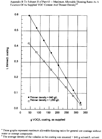
Table 1 to Subpart JJ of Part 63 - General Provisions Applicability to Subpart JJ
40:12.0.1.1.1.10.18.11.28 :
Table 1 to Subpart JJ of Part 63 - General Provisions Applicability to Subpart JJ| Reference | Applies to subpart JJ | Comment |
|---|---|---|
| 63.1(a) | Yes | |
| 63.1(b)(1) | No | Subpart JJ specifies applicability. |
| 63.1(b)(2) | Yes | |
| 63.1(b)(3) | Yes | |
| 63.1(c)(1) | No | Subpart JJ specifies applicability. |
| 63.1(c)(2) | No | Area sources are not subject to subpart JJ. |
| 63.1(c)(4) | Yes | |
| 63.1(c)(5) | Yes | |
| 63.1(c)(6) | Yes | |
| 63.1(e) | Yes | |
| 63.2 | Yes | Additional terms are defined in 63.801(a) of subpart JJ. When overlap between subparts A and JJ occurs, subpart JJ takes precedence. |
| 63.3 | Yes | Other units used in subpart JJ are defined in 63.801(b). |
| 63.4 | Yes | |
| 63.5 | Yes | |
| 63.6(a) | Yes | |
| 63.6(b)(1) | Yes | |
| 63.6(b)(2) | Yes | |
| 63.6(b)(3) | Yes | |
| 63.6(b)(4) | No | May apply when standards are proposed under Section 112(f) of the CAA. |
| 63.6(b)(5) | Yes | |
| 63.6(b)(7) | Yes | |
| 63.6(c)(1) | Yes | |
| 63.6(c)(2) | No | |
| 63.6(c)(5) | Yes | |
| 63.6(e)(1)(i) | No | See § 63.802(c) for general duty requirement. |
| 63.6(e)(1)(ii) | No. | |
| 63.6(e)(1)(iii) | Yes. | |
| 63.6(e)(2) | No | Section reserved. |
| 63.6(e)(3) | No. | |
| 63.6(f)(1) | No | Affected sources complying through the procedures specified in 63.804 (a)(1), (a)(2), (b), (c)(1), (d)(1), (d)(2), (e)(1), and (e)(2) are subject to the emission standards at all times, including periods of startup, shutdown, and malfunction. |
| 63.6(f)(2) | Yes | |
| 63.6(f)(3) | Yes | |
| 63.6(g) | Yes | |
| 63.6(h) | No | |
| 63.6 (i)(1)-(i)(3) | Yes | |
| 63.6(i)(4)(i) | Yes | |
| 63.6(i)(4)(ii) | No | |
| 63.6 (i)(5)-(i)(14) | Yes | |
| 63.6(i)(16) | Yes | |
| 63.6(j) | Yes | |
| 63.7(a)-(d) | Yes | Applies only to affected sources using a control device to comply with the rule. |
| 63.7(e)(1) | No | See § 63.805(a)(1). |
| 63.7(e)(2)-(e)(4) | Yes | Applies only to affected sources using a control device to comply with the rule. |
| 63.8(a)-(b) | Yes | Applies only to affected sources using a control device to comply with the rule. |
| 63.8(c)(1)(i) | No. | |
| 63.8(c)(1)(ii) | Yes | Applies only to affected sources using a control device to comply with the rule. |
| 63.8(c)(1)(iii) | No. | |
| 63.8(c)(2)-(d)(2) | Yes | Applies only to affected sources using a control device to comply with the rule. |
| 63.8(d)(3) | Yes, except for last sentence | Applies only to affected sources using a control device to comply with the rule. |
| 63.8(e)-(g) | Yes | Applies only to affected sources using a control device to comply with the rule. |
| 63.9(a) | Yes | |
| 63.9(b) | Yes | Existing sources are required to submit initial notification report within 270 days of the effective date or no later than 120 days after the source becomes subject to this subpart, whichever is later. |
| 63.9(c) | Yes | |
| 63.9(d) | Yes | |
| 63.9(e) | Yes | Applies only to affected sources using a control device to comply with the rule. |
| 63.9(f) | No | |
| 63.9(g) | Yes | Applies only to affected sources using a control device to comply with the rule. |
| 63.9(h) | Yes | 63.9(h)(2)(ii) applies only to affected sources using a control device to comply with the rule. |
| 63.9(i) | Yes | |
| 63.9(j) | Yes | |
| 63.9(k) | Yes | Only as specified in 63.9(j). |
| 63.10(a) | Yes | |
| 63.10(b)(1) | Yes | |
| 63.10(b)(2)(i) | No. | |
| 63.10(b)(2)(ii) | No | See § 63.806(k) for recordkeeping of occurrence and duration of malfunctions and recordkeeping of actions taken during malfunctions. |
| 63.10(b)(2)(iii) | Yes | Applies only to affected sources using a control device to comply with the rule. |
| 63.10(b)(2)(iv)-(b)(2)(v) | No. | |
| 63.10(b)(2)(vi)-(b)(2)(xiv) | Yes | Applies only to affected sources using a control device to comply with the rule. |
| 63.10(b)(3) | Yes | |
| 63.10(c)(1)-(9) | Yes. | |
| 63.10(c)(10)-(11) | No | See § 63.806(k) for recordkeeping of malfunctions. |
| 63.10(c)(12)-(14) | Yes. | |
| 63.10(c)(15) | No. | |
| 63.10(d)(1) | Yes | |
| 63.10(d)(2) | Yes | Applies only to affected sources using a control device to comply with the rule. |
| 63.10(d)(3) | No | |
| 63.10(d)(4) | Yes | |
| 63.10(d)(5) | No | See § 63.807(c)(3) for reporting of malfunctions. |
| 63.10(e) | Yes | Applies only to affected sources using a control device to comply with the rule. |
| 63.10(f) | Yes | |
| 63.11 | No | |
| 63.12-63.15 | Yes |
Table 2 to Subpart JJ of Part 63 - List of Volatile Hazardous Air Pollutants
40:12.0.1.1.1.10.18.11.29 :
Table 2 to Subpart JJ of Part 63 - List of Volatile Hazardous Air Pollutants| Chemical name | CAS No. |
|---|---|
| Acetaldehyde | 75070 |
| Acetamide | 60355 |
| Acetonitrile | 75058 |
| Acetophenone | 98862 |
| 2-Acetylaminofluorine | 53963 |
| Acrolein | 107028 |
| Acrylamide | 79061 |
| Acrylic acid | 79107 |
| Acrylonitrile | 107131 |
| Allyl chloride | 107051 |
| 4-Aminobiphenyl | 92671 |
| Aniline | 62533 |
| o-Anisidine | 90040 |
| Benzene | 71432 |
| Benzidine | 92875 |
| Benzotrichloride | 98077 |
| Benzyl chloride | 100447 |
| Biphenyl | 92524 |
| Bis (2-ethylhexyl) phthalate (DEHP) | 117817 |
| Bis (chloromethyl) ether | 542881 |
| Bromoform | 75252 |
| 1,3-Butadiene | 106990 |
| Carbon disulfide | 75150 |
| Carbon tetrachloride | 56235 |
| Carbonyl sulfide | 463581 |
| Catechol | 120809 |
| Chloroacetic acid | 79118 |
| 2-Chloroacetophenone | 532274 |
| Chlorobenzene | 108907 |
| Chloroform | 67663 |
| Chloromethyl methyl ether | 107302 |
| Chloroprene | 126998 |
| Cresols (isomers and mixture) | 1319773 |
| o-Cresol | 95487 |
| m-Cresol | 108394 |
| p-Cresol | 106445 |
| Cumene | 98828 |
| 2,4-D (2,4-Dichlorophenoxyacetic acid, including salts and esters) | 94757 |
| DDE (1,1-Dichloro-2,2-bis(p-chlorophenyl)ethylene) | 72559 |
| Diazomethane | 334883 |
| Dibenzofuran | 132649 |
| 1,2-Dibromo-3-chloropropane | 96128 |
| Dibutylphthalate | 84742 |
| 1,4-Dichlorobenzene | 106467 |
| 3,3′-Dichlorobenzidine | 91941 |
| Dichloroethyl ether (Bis(2-chloroethyl)ether) | 111444 |
| 1,3-Dichloropropene | 542756 |
| Diethanolamine | 111422 |
| N,N-Dimethylaniline | 121697 |
| Diethyl sulfate | 64675 |
| 3,3′-Dimethoxybenzidine | 119904 |
| 4-Dimethylaminoazobenzene | 60117 |
| 3,3′-Dimethylbenzidine | 119937 |
| Dimethylcarbamoyl chloride | 79447 |
| N,N-Dimethylformamide | 68122 |
| 1,1-Dimethylhydrazine | 57147 |
| Dimethyl phthalate | 131113 |
| Dimethyl sulfate | 77781 |
| 4,6-Dinitro-o-cresol, and salts | 534521 |
| 2,4-Dinitrophenol | 51285 |
| 2,4-Dinitrotoluene | 121142 |
| 1,4-Dioxane (1,4-Diethyleneoxide) | 123911 |
| 1,2-Diphenylhydrazine | 122667 |
| Epichlorohydrin (1-Chloro-2,3-epoxypropane) | 106898 |
| 1,2-Epoxybutane | 106887 |
| Ethyl acrylate | 140885 |
| Ethylbenzene | 100414 |
| Ethyl carbamate (Urethane) | 51796 |
| Ethyl chloride (Chloroethane) | 75003 |
| Ethylene dibromide (Dibromoethane) | 106934 |
| Ethylene dichloride (1,2-Dichloroethane) | 107062 |
| Ethylene glycol | 107211 |
| Ethylene oxide | 75218 |
| Ethylenethiourea | 96457 |
| Ethylidene dichloride (1,1-Dichloroethane) | 75343 |
| Formaldehyde | 50000 |
| Glycolethers a | |
| Hexachlorobenzene | 118741 |
| Hexachloro-1,3-butadiene | 87683 |
| Hexachloroethane | 67721 |
| Hexamethylene-1,6-diisocyanate | 822060 |
| Hexamethylphosphoramide | 680319 |
| Hexane | 110543 |
| Hydrazine | 302012 |
| Hydroquinone | 123319 |
| Isophorone | 78591 |
| Maleic anhydride | 108316 |
| Methanol | 67561 |
| Methyl bromide (Bromomethane) | 74839 |
| Methyl chloride (Chloromethane) | 74873 |
| Methyl chloroform (1,1,1-Trichloroethane) | 71556 |
| Methyl ethyl ketone (2-Butanone) | 78933 |
| Methylhydrazine | 60344 |
| Methyl iodide (Iodomethane) | 74884 |
| Methyl isobutyl ketone (Hexone) | 108101 |
| Methyl isocyanate | 624839 |
| Methyl methacrylate | 80626 |
| Methyl tert-butyl ether | 1634044 |
| 4,4′-Methylenebis (2-chloroaniline) | 101144 |
| Methylene chloride (Dichloromethane) | 75092 |
| 4,4′-Methylenediphenyl diisocyanate (MDI) | 101688 |
| 4,4′-Methylenedianiline | 101779 |
| Naphthalene | 91203 |
| Nitrobenzene | 98953 |
| 4-Nitrobiphenyl | 92933 |
| 4-Nitrophenol | 100027 |
| 2-Nitropropane | 79469 |
| N-Nitroso-N-methylurea | 684935 |
| N-Nitrosodimethylamine | 62759 |
| N-Nitrosomorpholine | 59892 |
| Phenol | 108952 |
| p-Phenylenediamine | 106503 |
| Phosgene | 75445 |
| Phthalic anhydride | 85449 |
| Polychlorinated biphenyls (Aroclors) | 1336363 |
| Polycyclic Organic Matter b | |
| 1,3-Propane sultone | 1120714 |
| beta-Propiolactone | 57578 |
| Propionaldehyde | 123386 |
| Propoxur (Baygon) | 114261 |
| Propylene dichloride (1,2-Dichloropropane) | 78875 |
| Propylene oxide | 75569 |
| 1,2-Propylenimine (2-Methyl aziridine) | 75558 |
| Quinone | 106514 |
| Styrene | 100425 |
| Styrene oxide | 96093 |
| 2,3,7,8-Tetrachlorodibenzo-p-dioxin | 1746016 |
| 1,1,2,2-Tetrachloroethane | 79345 |
| Tetrachloroethylene (Perchloroethylene) | 127184 |
| Toluene | 108883 |
| 2,4-Toluenediamine | 95807 |
| Toluene-2,4-diisocyanate | 584849 |
| o-Toluidine | 95534 |
| 1,2,4-Trichlorobenzene | 120821 |
| 1,1,2-Trichloroethane | 79005 |
| Trichloroethylene | 79016 |
| 2,4,5-Trichlorophenol | 95954 |
| 2,4,6-Trichlorophenol | 88062 |
| Triethylamine | 121448 |
| Trifluralin | 1582098 |
| 2,2,4-Trimethylpentane | 540841 |
| Vinyl acetate | 108054 |
| Vinyl bromide | 593602 |
| Vinyl chloride | 75014 |
| Vinylidene chloride (1,1-Dichloroethylene) | 75354 |
| Xylenes (isomers and mixture) | 1330207 |
| o-Xylene | 95476 |
| m-Xylene | 108383 |
| p-Xylene | 106423 |
a Includes mono- and di-ethers of ethylene glycol, diethylene glycols and triethylene glycol; R-(OCH2CH2) RR-OR where:
n = 1, 2, or 3,
R = alkyl or aryl groups
R′= R, H, or groups which, when removed, yield glycol ethers with the structure: R-(OCH2CH2)n - OH. Polymers are excluded from the glycol category.
b Includes organic compounds with more than one benzene ring, and which have a boiling point greater than or equal to 100°C.
Table 3 to Subpart JJ of Part 63 - Summary of Emission Limits
40:12.0.1.1.1.10.18.11.30 :
Table 3 to Subpart JJ of Part 63 - Summary of Emission Limits| Emission point | Existing source | New source |
|---|---|---|
| Finishing Operations: | ||
| (a) Achieve a weighted average VHAP content across all coatings (maximum kg VHAP/kg solids [lb VHAP/lb solids], as applied | a 1.0 | a 0.8 |
| (b) Use compliant finishing materials (maximum kg VHAP/kg solids [lb VHAP/lb solids], as applied): | ||
| - stains | a 1.0 | a 1.0 |
| - washcoats | a b 1.0 | a b 0.8 |
| - sealers | a 1.0 | a 0.8 |
| - topcoats | a 1.0 | a 0.8 |
| - basecoats | a b 1.0 | a b 0.8 |
| - enamels | a b 1.0 | a b 0.8 |
| - thinners (maximum percent VHAP allowable); or | 10.0 | 10.0 |
| (c) As an alternative, use control device; or | c 1.0 | c 0.8 |
| (d) Use any combination of (a), (b), and (c) | 1.0 | 0.8 |
| Cleaning Operations: | ||
| Strippable spray booth material (maximum VOC content, kg VOC/kg solids [lb VOC/lb solids]) | 0.8 | 0.8 |
| Contact Adhesives: | ||
| (a) Use compliant contact adhesives (maximum kg VHAP/kg solids [lb VHAP/lb solids], as applied) based on following criteria: | ||
| i. For aerosol adhesives, and for contact adhesives applied to nonporous substrates | d NA | d NA |
| ii. For foam adhesives used in products that meet flammability requirements | 1.8 | 0.2 |
| iii. For all other contact adhesives (including foam adhesives used in products that do not meet flammability requirements); or | 1.0 | 0.2 |
| (b) Use a control device | e 1.0 | e 0.2 |
| All Finishing Operations and Contact Adhesives: | ||
| (a) Achieve total free formaldehyde emissions across all finishing operations and contact adhesives, lb per rolling 12 month period, as applied | 400 | 400 |
| (b) Use coatings and contact adhesives only if they are low-formaldehyde coatings and contact adhesives | f 1.0 | f 1.0 |
a The limits refer to the VHAP content of the coating, as applied.
b Washcoats, basecoats, and enamels must comply with the limits presented in this table if they are purchased premade, that is, if they are not formulated onsite by thinning other finishing materials. If they are formulated onsite, they must be formulated using compliant finishing materials, i.e., those that meet the limits specified in this table, and thinners containing no more than 3.0 percent VHAP by weight.
c The control device must operate at an efficiency that is equivalent to no greater than 1.0 kilogram (or 0.8 kilogram) of VHAP being emitted from the affected emission source per kilogram of solids used.
d There is no limit on the VHAP content of these adhesives.
e The control device must operate at an efficiency that is equivalent to no greater than 1.0 kilogram (or 0.2 kilogram) of VHAP being emitted from the affected emission source per kilogram of solids used.
f The limits refer to the formaldehyde content by weight of the coating or contact adhesive, as specified on certified product data sheets.
Table 4 to Subpart JJ of Part 63 - Pollutants Excluded From Use in Cleaning and Washoff Solvents
40:12.0.1.1.1.10.18.11.31 :
Table 4 to Subpart JJ of Part 63 - Pollutants Excluded From Use in Cleaning and Washoff Solvents| Chemical name | CAS No. |
|---|---|
| 4-Aminobiphenyl | 92671 |
| Styrene oxide | 96093 |
| Diethyl sulfate | 64675 |
| N-Nitrosomorpholine | 59892 |
| Dimethyl formamide | 68122 |
| Hexamethylphosphoramide | 680319 |
| Acetamide | 60355 |
| 4,4′-Methylenedianiline | 101779 |
| o-Anisidine | 90040 |
| 2,3,7,8-Tetrachlorodibenzo-p-dioxin | 1746016 |
| Beryllium salts | |
| Benzidine | 92875 |
| N-Nitroso-N-methylurea | 684935 |
| Bis (chloromethyl) ether | 542881 |
| Dimethyl carbamoyl chloride | 79447 |
| Chromium compounds (hexavalent) | |
| 1,2-Propylenimine (2-Methyl aziridine) | 75558 |
| Arsenic and inorganic arsenic compounds | 99999904 |
| Hydrazine | 302012 |
| 1,1-Dimethyl hydrazine | 57147 |
| Beryllium compounds | 7440417 |
| 1,2-Dibromo-3-chloropropane | 96128 |
| N-Nitrosodimethylamine | 62759 |
| Cadmium compounds | |
| Benzo (a) pyrene | 50328 |
| Polychlorinated biphenyls (Aroclors) | 1336363 |
| Heptachlor | 76448 |
| 3,3′-Dimethyl benzidine | 119937 |
| Nickel subsulfide | 12035722 |
| Acrylamide | 79061 |
| Hexachlorobenzene | 118741 |
| Chlordane | 57749 |
| 1,3-Propane sultone | 1120714 |
| 1,3-Butadiene | 106990 |
| Nickel refinery dust | |
| 2-Acetylaminoflourine | 53963 |
| 3,3′-Dichlorobenzidine | 53963 |
| Lindane (hexachlorcyclohexane, gamma) | 58899 |
| 2,4-Toluene diamine | 95807 |
| Dichloroethyl ether (Bis(2-chloroethyl) ether) | 111444 |
| 1,2-Diphenylhydrazine | 122667 |
| Toxaphene (chlorinated camphene) | 8001352 |
| 2,4-Dinitrotoluene | 121142 |
| 3,3′-Dimethoxybenzidine | 119904 |
| Formaldehyde | 50000 |
| 4,4′-Methylene bis (2-chloroaniline) | 101144 |
| Acrylonitrile | 107131 |
| Ethylene dibromide (1,2-Dibromoethane) | 106934 |
| DDE (1,1-p-chlorophenyl 1-2 dichloroethylene) | 72559 |
| Chlorobenzilate | 510156 |
| Dichlorvos | 62737 |
| Vinyl chloride | 75014 |
| Coke Oven Emissions | |
| Ethylene oxide | 75218 |
| Ethylene thiourea | 96457 |
| Vinyl bromide (bromoethene) | 593602 |
| Selenium sulfide (mono and di) | 7488564 |
| Chloroform | 67663 |
| Pentachlorophenol | 87865 |
| Ethyl carbamate (Urethane) | 51796 |
| Ethylene dichloride (1,2-Dichloroethane) | 107062 |
| Propylene dichloride (1,2-Dichloropropane) | 78875 |
| Carbon tetrachloride | 56235 |
| Benzene | 71432 |
| Methyl hydrazine | 60344 |
| Ethyl acrylate | 140885 |
| Propylene oxide | 75569 |
| Aniline | 62533 |
| 1,4-Dichlorobenzene(p) | 106467 |
| 2,4,6-Trichlorophenol | 88062 |
| Bis (2-ethylhexyl) phthalate (DEHP) | 117817 |
| o-Toluidine | 95534 |
| Propoxur | 114261 |
| 1,4-Dioxane (1,4-Diethyleneoxide) | 123911 |
| Acetaldehyde | 75070 |
| Bromoform | 75252 |
| Captan | 133062 |
| Epichlorohydrin | 106898 |
| Methylene chloride (Dichloromethane) | 75092 |
| Dibenz (ah) anthracene | 53703 |
| Chrysene | 218019 |
| Dimethyl aminoazobenzene | 60117 |
| Benzo (a) anthracene | 56553 |
| Benzo (b) fluoranthene | 205992 |
| Antimony trioxide | 1309644 |
| 2-Nitropropane | 79469 |
| 1,3-Dichloropropene | 542756 |
| 7, 12-Dimethylbenz(a) anthracene | 57976 |
| Benz(c) acridine | 225514 |
| Indeno(1,2,3-cd)pyrene | 193395 |
| 1,2:7,8-Dibenzopyrene | 189559 |
Table 5 to Subpart JJ of Part 63 - List of VHAP of Potential Concern Identified by Industry
40:12.0.1.1.1.10.18.11.32 :
Table 5 to Subpart JJ of Part 63 - List of VHAP of Potential Concern Identified by Industry| CAS No. | Chemical name | EPA de minimis, tons/yr |
|---|---|---|
| 68122 | Dimethyl formamide | 1.0 |
| 50000 | Formaldehyde | 0.2 |
| 75092 | Methylene chloride | 4.0 |
| 79469 | 2-Nitropropane | 1.0 |
| 78591 | Isophorone | 0.7 |
| 1000425 | Styrene monomer | 1.0 |
| 108952 | Phenol | 0.1 |
| 111422 | Dimethanolamine | 5.0 |
| 109864 | 2-Methoxyethanol | 10.0 |
| 111159 | 2-Ethoxyethyl acetate | 10.0 |
Table 6 to Subpart JJ of Part 63 - VHAP of Potential Concern
40:12.0.1.1.1.10.18.11.33 :
Table 6 to Subpart JJ of Part 63 - VHAP of Potential Concern| CAS No. | Chemical name | EPA de minimis, tons/yr* |
|---|---|---|
| 92671 | 4-Aminobiphenyl | 1.0 |
| 96093 | Styrene oxide | 1.0 |
| 64675 | Diethyl sulfate | 1.0 |
| 59892 | N-Nitrosomorpholine | 1.0 |
| 68122 | Dimethyl formamide | 1.0 |
| 680319 | Hexamethylphosphoramide | 0.01 |
| 60355 | Acetamide | 1.0 |
| 101779 | 4,4′-Methylenedianiline | 1.0 |
| 90040 | o-Anisidine | 1.0 |
| 1746016 | 2,3,7,8-Tetrachlorodibenzo-p-dioxin | 0.00000006 |
| 92875 | Benzidine | 0.00003 |
| 684935 | N-Nitroso-N-methylurea | 0.00002 |
| 542881 | Bis(chloromethyl) ether | 0.00003 |
| 79447 | Dimethyl carbamoyl chloride | 0.002 |
| 75558 | 1,2-Propylenimine (2-Methyl aziridine) | 0.0003 |
| 57147 | 1,1-Dimethyl hydrazine | 0.0008 |
| 96128 | 1,2-Dibromo-3-chloropropane | 0.001 |
| 62759 | N-Nitrosodimethylamine | 0.0001 |
| 50328 | Benzo (a) pyrene | 0.001 |
| 1336363 | Polychlorinated biphenyls (Aroclors) | 0.0009 |
| 76448 | Heptachlor | 0.002 |
| 119937 | 3,3′-Dimethyl benzidine | 0.001 |
| 79061 | Acrylamide | 0.002 |
| 118741 | Hexachlorobenzene | 0.004 |
| 57749 | Chlordane | 0.005 |
| 1120714 | 1,3-Propane sultone | 0.003 |
| 106990 | 1,3-Butadiene | 0.007 |
| 53963 | 2-Acetylaminoflourine | 0.0005 |
| 91941 | 3,3′-Dichlorobenzidine | 0.02 |
| 58899 | Lindane (hexachlorocyclohexane, gamma) | 0.005 |
| 95807 | 2,4-Toluene diamine | 0.002 |
| 111444 | Dichloroethyl ether (Bis(2-chloroethyl)ether) | 0.006 |
| 122667 | 1,2 - Diphenylhydrazine | 0.009 |
| 8001352 | Toxaphene (chlorinated camphene) | 0.006 |
| 121142 | 2,4-Dinitrotoluene | 0.002 |
| 119904 | 3,3′-Dimethoxybenzidine | 0.01 |
| 50000 | Formaldehyde | 0.2 |
| 101144 | 4,4′-Methylene bis(2-chloroaniline) | 0.02 |
| 107131 | Acrylonitrile | 0.03 |
| 106934 | Ethylene dibromide(1,2-Dibromoethane) | 0.01 |
| 72559 | DDE (1,1-p-chlorophenyl 1-2 dichloroethylene) | 0.01 |
| 510156 | Chlorobenzilate | 0.04 |
| 62737 | Dichlorvos | 0.02 |
| 75014 | Vinyl chloride | 0.02 |
| 75218 | Ethylene oxide | 0.09 |
| 96457 | Ethylene thiourea | 0.06 |
| 593602 | Vinyl bromide (bromoethene) | 0.06 |
| 67663 | Chloroform | 0.09 |
| 87865 | Pentachlorophenol | 0.07 |
| 51796 | Ethyl carbamate (Urethane) | 0.08 |
| 107062 | Ethylene dichloride (1,2-Dichloroethane) | 0.08 |
| 78875 | Propylene dichloride (1,2-Dichloropropane) | 0.1 |
| 56235 | Carbon tetrachloride | 0.1 |
| 71432 | Benzene | 0.2 |
| 140885 | Ethyl acrylate | 0.1 |
| 75569 | Propylene oxide | 0.5 |
| 62533 | Aniline | 0.1 |
| 106467 | 1,4-Dichlorobenzene(p) | 0.3 |
| 88062 | 2,4,6-Trichlorophenol | 0.6 |
| 117817 | Bis (2-ethylhexyl) phthalate (DEHP) | 0.5 |
| 95534 | o-Toluidine | 0.4 |
| 114261 | Propoxur | 2.0 |
| 79016 | Trichloroethylene | 1.0 |
| 123911 | 1,4-Dioxane (1,4-Diethyleneoxide) | 0.6 |
| 75070 | Acetaldehyde | 0.9 |
| 75252 | Bromoform | 2.0 |
| 133062 | Captan | 2.0 |
| 106898 | Epichlorohydrin | 2.0 |
| 75092 | Methylene chloride (Dichloromethane) | 4.0 |
| 127184 | Tetrachloroethylene (Perchloroethylene) | 4.0 |
| 53703 | Dibenz (ah) anthracene | 0.01 |
| 218019 | Chrysene | 0.01 |
| 60117 | Dimethyl aminoazobenzene | 1.0 |
| 56553 | Benzo (a) anthracene | 0.01 |
| 205992 | Benzo (b) fluoranthene | 0.01 |
| 79469 | 2-Nitropropane | 1.0 |
| 542756 | 1,3-Dichloropropene | 1.0 |
| 57976 | 7,12-Dimethylbenz (a) anthracene | 0.01 |
| 225514 | Benz(c)acridine | 0.01 |
| 193395 | Indeno(1,2,3-cd)pyrene | 0.01 |
| 189559 | 1,2:7,8-Dibenzopyrene | 0.01 |
| 79345 | 1,1,2,2-Tetrachloroethane | 0.03 |
| 91225 | Quinoline | 0.0006 |
| 75354 | Vinylidene chloride (1,1-Dichloroethylene) | 0.04 |
| 87683 | Hexachlorobutadiene | 0.09 |
| 82688 | Pentachloronitrobenzene (Quintobenzene) | 0.03 |
| 78591 | Isophorone | 0.7 |
| 79005 | 1,1,2-Trichloroethane | 0.1 |
| 74873 | Methyl chloride (Chloromethane) | 1.0 |
| 67721 | Hexachloroethane | 0.5 |
| 1582098 | Trifluralin | 0.9 |
| 1319773 | Cresols/Cresylic acid (isomers and mixture) | 1.0 |
| 108394 | m-Cresol | 1.0 |
| 75343 | Ethylidene dichloride (1,1-Dichloroethane) | 1.0 |
| 95487 | o-Cresol | 1.0 |
| 106445 | p-Cresol | 1.0 |
| 74884 | Methyl iodide (Iodomethane) | 1.0 |
| 100425 | Styrene | 1.0 |
| 107051 | Allyl chloride | 1.0 |
| 334883 | Diazomethane | 1.0 |
| 95954 | 2,4,5 - Trichlorophenol | 1.0 |
| 133904 | Chloramben | 1.0 |
| 106887 | 1,2 - Epoxybutane | 1.0 |
| 108054 | Vinyl acetate | 1.0 |
| 126998 | Chloroprene | 1.0 |
| 123319 | Hydroquinone | 1.0 |
| 92933 | 4-Nitrobiphenyl | 1.0 |
| 56382 | Parathion | 0.1 |
| 13463393 | Nickel Carbonyl | 0.1 |
| 60344 | Methyl hydrazine | 0.006 |
| 151564 | Ethylene imine | 0.0003 |
| 77781 | Dimethyl sulfate | 0.1 |
| 107302 | Chloromethyl methyl ether | 0.1 |
| 57578 | beta-Propiolactone | 0.1 |
| 100447 | Benzyl chloride | 0.04 |
| 98077 | Benzotrichloride | 0.0006 |
| 107028 | Acrolein | 0.04 |
| 584849 | 2,4 - Toluene diisocyanate | 0.1 |
| 75741 | Tetramethyl lead | 0.01 |
| 78002 | Tetraethyl lead | 0.01 |
| 12108133 | Methylcyclopentadienyl manganese | 0.1 |
| 624839 | Methyl isocyanate | 0.1 |
| 77474 | Hexachlorocyclopentadiene | 0.1 |
| 62207765 | Fluomine | 0.1 |
| 10210681 | Cobalt carbonyl | 0.1 |
| 79118 | Chloroacetic acid | 0.1 |
| 534521 | 4,6-Dinitro-o-cresol, and salts | 0.1 |
| 101688 | Methylene diphenyl diisocyanate | 0.1 |
| 108952 | Phenol | 0.1 |
| 62384 | Mercury, (acetato-o) phenyl | 0.01 |
| 98862 | Acetophenone | 1.0 |
| 108316 | Maleic anhydride | 1.0 |
| 532274 | 2-Chloroacetophenone | 0.06 |
| 51285 | 2,4-Dinitrophenol | 1.0 |
| 109864 | 2-Methyoxy ethanol | 10.0 |
| 98953 | Nitrobenzene | 1.0 |
| 74839 | Methyl bromide (Bromomethane) | 10.0 |
| 75150 | Carbon disulfide | 1.0 |
| 121697 | N,N-Dimethylaniline | 1.0 |
| 106514 | Quinone | 5.0 |
| 123386 | Propionaldehyde | 5.0 |
| 120809 | Catechol | 5.0 |
| 85449 | Phthalic anhydride | 5.0 |
| 463581 | Carbonyl sulfide | 5.0 |
| 132649 | Dibenzofurans | 5.0 |
| 100027 | 4-Nitrophenol | 5.0 |
| 540841 | 2,2,4-Trimethylpentane | 5.0 |
| 111422 | Diethanolamine | 5.0 |
| 822060 | Hexamethylene-1,6-diisocyanate | 5.0 |
| Glycol ethers a | 5.0 | |
| Polycyclic organic matter b | 0.01 |
* These values are based on the de minimis levels provided in the proposed rulemaking pursuant to section 112(g) of the Act using a 70-year lifetime exposure duration for all VHAP. Default assumptions and the de minimis values based on inhalation reference doses (RfC) are not changed by this adjustment.
a Except for ethylene glycol butyl ether, ethylene glycol ethyl ether (2-ethoxy ethanol), ethylene glycol hexyl ether, ethylene glycol methyl ether (2-methoxyethanol), ethylene glycol phenyl ether, ethylene glycol propyl ether, ethylene glycol mono-2-ethylhexyl ether, diethylene glycol butyl ether, diethylene glycol ethyl ether, diethylene glycol methyl ether, diethylene glycol hexyl ether, diethylene glycol phenyl ether, diethylene glycol propyl ether, triethylene glycol butyl ether, triethylene glycol ethyl ether, triethylene glycol methyl ether, triethylene glycol propyl ether, ethylene glycol butyl ether acetate, ethylene glycol ethyl ether acetate, and diethylene glycol ethyl ether acetate.
b Except for benzo(b)fluoranthene, benzo(a)anthracene, benzo(a)pyrene, 7,12-dimethylbenz(a)anthracene, benz(c)acridine, chrysene, dibenz(ah) anthracene, 1,2:7,8-dibenzopyrene, indeno(1,2,3-cd)pyrene, but including dioxins and furans.
Table 1 to Subpart KK of Part 63 - Applicability of General Provisions to Subpart KK
40:12.0.1.1.1.11.18.14.34 :
Table 1 to Subpart KK of Part 63 - Applicability of General Provisions to Subpart KK| General provisions reference | Applicable to subpart KK | Comment |
|---|---|---|
| § 63.1(a)(1)-(a)(4) | Yes. | |
| § 63.1(a)(5) | No | Section reserved. |
| § 63.1(a)(6)-(a)(8) | No. | |
| § 63.1(a)(9) | No | Section reserved. |
| § 63.1(a)(10)-(a)(14) | Yes. | |
| § 63.1(b)(1) | No | Subpart KK specifies applicability. |
| § 63.1(b)(2)-(b)(3) | Yes. | |
| § 63.1(c)(1) | Yes. | |
| § 63.1(c)(2) | No | Area sources are not subject to subpart KK. |
| § 63.1(c)(3) | No | Section reserved. |
| § 63.1(c)(4) | Yes. | |
| § 63.1(c)(5) | No. | |
| § 63.1(c)(6) | Yes | |
| § 63.1(d) | No | Section reserved. |
| § 63.1(e) | Yes. | |
| § 63.2 | Yes | Additional definitions in subpart KK. |
| § 63.3(a)-(c) | Yes. | |
| § 63.4(a)(1)-(a)(3) | Yes. | |
| § 63.4(a)(4) | No | Section reserved. |
| § 63.4(a)(5) | Yes. | |
| § 63.4(b)-(c) | Yes. | |
| § 63.5(a)(1)-(a)(2) | Yes. | |
| § 63.5(b)(1) | Yes. | |
| § 63.5(b)(2) | No | Section reserved. |
| § 63.5(b)(3)-(b)(6) | Yes. | |
| § 63.5(c) | No | Section reserved. |
| § 63.5(d) | Yes. | |
| § 63.5(e) | Yes. | |
| § 63.5(f) | Yes. | |
| § 63.6(a) | Yes. | |
| § 63.6(b)(1)-(b)(5) | Yes. | |
| § 63.6(b)(6) | No | Section reserved. |
| § 63.6(b)(7) | Yes. | |
| § 63.6(c)(1)-(c)(2) | Yes. | |
| § 63.6(c)(3)-(c)(4) | No | Sections reserved. |
| § 63.6(c)(5) | Yes. | |
| § 63.6(d) | No | Section reserved. |
| § 63.6(e)(1)(i) | No | See 63.823(b) for general duty requirement. Any cross-reference to 63.6(e)(1)(i) in any other general provision incorporated by reference shall be treated as a cross-reference to 63.823(b). |
| § 63.6(e)(1)(ii) | No | |
| § 63.6(e)(1)(iii) | Yes. | |
| § 63.6(e)(2) | No | Section reserved. |
| § 63.6(e)(3) | No | |
| § 63.6(f)(1) | No | |
| § 63.6(f)(2)-(f)(3) | Yes. | |
| § 63.6(g) | Yes. | |
| § 63.6(h) | No | Subpart KK does not require COMS. |
| § 63.6(i)(1)-(i)(14) | Yes. | |
| § 63.6(i)(15) | No | Section reserved. |
| § 63.6(i)(16) | Yes. | |
| § 63.6(j) | Yes. | |
| § 63.7(a)-(d) | Yes. | |
| § 63.7(e)(1) | No | See 63.827 introductory text. Any cross-reference to 63.7(e)(1) in any other general provision incorporated by reference shall be treated as a cross-reference to 63.827 introductory text. |
| § 63.7(e)(2)-(e)(4) | Yes. | |
| § 63.8(a)(1)-(a)(2) | Yes. | |
| § 63.8(a)(3) | No | Section reserved. |
| § 63.8(a)(4) | No | Subpart KK specifies the use of solvent recovery devices or oxidizers. |
| § 63.8(b) | Yes. | |
| § 63.8(c)(1)-(3) | Yes. | |
| § 63.8(c)(4) | No | Subpart KK specifies CMS sampling requirements. |
| § 63.8(c)(5) | No | Subpart KK does not require COMS. |
| § 63.8(c)(6)-(c)(8) | Yes | Provisions for COMS are not applicable. |
| § 63.8(d)(1)-(2) | Yes. | |
| § 63.8(d)(3) | Yes, except for last sentence. | |
| § 63.8(e)-(f) | Yes. | |
| § 63.8(g) | No | Subpart KK specifies CMS data reduction requirements. |
| § 63.9(a) | Yes. | |
| § 63.9(b)(1) | Yes. | |
| § 63.9(b)(2) | Yes | Initial notification submission date extended. |
| § 63.9(b)(3)-(b)(5) | Yes. | |
| § 63.9(c)-(e) | Yes. | |
| § 63.9(f) | No | Subpart KK does not require opacity and visible emissions observations. |
| § 63.9(g) | Yes | Provisions for COMS are not applicable. |
| § 63.9(h)(1)-(h)(3) | Yes. | |
| § 63.9(h)(4) | No | Section reserved. |
| § 63.9(h)(5)-(h)(6) | Yes. | |
| § 63.9(i) | Yes. | |
| § 63.9(j) | Yes. | |
| § 63.9(k) | Yes | Only as specified in 63.9(j). |
| § 63.10(a) | Yes. | |
| § 63.10(b)(1) | Yes. | |
| § 63.10(b)(2)(i) | No. | |
| § 63.10(b)(2)(ii) | No | See 63.829(g) for recordkeeping of occurrence and duration of malfunctions. See 63.829(h) for recordkeeping of actions taken during malfunction. Any cross-reference to 63.10(b)(2)(ii) in any other general provision incorporated by reference shall be treated as a cross-reference to 63.829(g). |
| § 63.10(b)(2)(iii) | Yes. | |
| § 63.10(b)(2)(iv)-(b)(2)(v) | No. | |
| § 63.10(b)(2)(vi)-(b)(2)(xiv) | Yes. | |
| § 63.10(b)(3) | Yes. | |
| § 63.10(c)(1) | Yes. | |
| § 63.10(c)(2)-(c)(4) | No | Sections reserved. |
| § 63.10(c)(5)-(c)(8) | Yes. | |
| § 63.10(c)(9) | No | Section reserved. |
| § 63.10(c)(10) | No | See 63.830(b)(6)(v) for reporting malfunctions. Any cross-reference to 63.10(c)(10) in any other general provision incorporated by reference shall be treated as a cross-reference to 63.830(b)(6)(v). |
| § 63.10(c)(11) | No | See 63.830(b)(6)(v) for reporting malfunctions. Any cross-reference to 63.10(c)(11) in any other general provision incorporated by reference shall be treated as a cross-reference to 63.830(b)(6)(v). |
| § 63.10(c)(12)-(c)(14) | Yes. | |
| § 63.10(c)(15) | No. | |
| § 63.10(d)(1)-(d)(2) | Yes. | |
| § 63.10(d)(3) | No | Subpart KK does not require opacity and visible emissions observations. |
| § 63.10(d)(4) | Yes. | |
| § 63.10(d)(5) | No. | |
| § 63.10(e) | Yes | Provisions for COMS are not applicable. |
| § 63.10(f) | Yes. | |
| § 63.11 | No | Subpart KK specifies the use of solvent recovery devices or oxidizers. |
| § 63.12 | Yes. | |
| § 63.13 | Yes. | |
| § 63.14 | Yes. | |
| § 63.15 | Yes. |
Appendix A to Subpart KK of Part 63 - Data Quality Objective and Lower Confidence Limit Approaches for Alternative Capture Efficiency Protocols and Test Methods
40:12.0.1.1.1.11.18.14.35 : Appendix A
Appendix A to Subpart KK of Part 63 - Data Quality Objective and Lower Confidence Limit Approaches for Alternative Capture Efficiency Protocols and Test Methods 1. Introduction1.1 Alternative capture efficiency (CE) protocols and test methods that satisfy the criteria of either the data quality objective (DQO) approach or the lower confidence limit (LCL) approach are acceptable under § 63.827(f). The general criteria for alternative CE protocols and test methods to qualify under either the DQO or LCL approach are described in section 2. The DQO approach and criteria specific to the DQO approach are described in section 3. The LCL approach and criteria specific to the LCL approach are described in section 4. The recommended reporting for alternative CE protocols and test methods are presented in section 5. The recommended recordkeeping for alternative CE protocols and test methods are presented in section 6.
1.2 Although the Procedures L, G.1, G.2, F.1, and F.2 in § 52.741 of part 52 were developed for TTE and BE testing, the same procedures can also be used in an alternative CE protocol. For example, a traditional liquid/gas mass balance CE protocol could employ Procedure L to measure liquid VOC input and Procedure G.1 to measure captured VOC.
2. General Criteria for DQO and LCL Approaches2.1 The following general criteria must be met for an alternative capture efficiency protocol and test methods to qualify under the DQO or LCL approach.
2.2 An alternative CE protocol must consist of at least three valid test runs. Each test run must be at least 20 minutes long. No test run can be longer than 24 hours.
2.3 All test runs must be separate and independent. For example, liquid VOC input and output must be determined independently for each run. The final liquid VOC sample from one run cannot be the initial sample for another run. In addition, liquid input for an entire day cannot be apportioned among test runs based on production.
2.4 Composite liquid samples cannot be used to obtain an “average composition” for a test run. For example, separate initial and final coating samples must be taken and analyzed for each run; initial and final samples cannot be combined prior to analysis to derive an “average composition” for the test run.
2.5 All individual test runs that result in a CE of greater than 105 percent are invalid and must be discarded.
2.6 If the source can demonstrate to the regulatory agency that a test run should not be considered due to an identified testing or analysis error such as spillage of part of the sample during shipping or an upset or improper operating conditions that is not considered part of normal operation then the test result for that individual test run may be discarded. This limited exception allows sources to discard as “outliers” certain individual test runs without replacing them with a valid test run as long as the facility has at least three valid test runs to use when calculating its DQO or LCL. This exception is limited solely to test runs involving the types of errors identified above.
2.7 All valid test runs that are conducted must be included in the average CE determination. The individual test run CE results and average CE results cannot be truncated (i.e., 105 percent cannot be reported as 100 + percent) for purposes of meeting general or specific criteria for either the DQO or the LCL. If the DQO is satisfied and the average CE is greater than 100, then 100 percent CE must be considered the result of the test.
2.8 Alternative test methods for measuring VOC concentration must include a three-point calibration of the gas analysis instrument in the expected concentration range.
3. Data Quality Objective Approach3.1 The purpose of the DQO is to allow sources to use alternative CE protocols and test methods while ensuring reasonable precision consistent with pertinent requirements of the Clean Air Act. In addition to the general criteria described in section 2, the specific DQO criterion is that the width of the two-sided 95 percent confidence interval of the mean measured value must be less than or equal to 10 percent of the mean measured value (see Figure 1). This ensures that 95 percent of the time, when the DQO is met, the actual CE value will be ±5 percent of the mean measured value (assuming that the test protocol is unbiased).
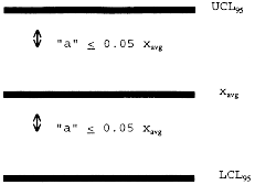
3.2 The DQO calculation is made as follows using Equations 1 and 2:
Where: a = Distance from the average measured CE value to the endpoints of the 95-percent (two-sided) confidence interval for the measured value. n = Number of valid test runs. P = DQO indicator statistic, distance from the average measured CE value to the endpoints of the 95-percent (two-sided) confidence interval, expressed as a percent of the average measured CE value. s = Sample standard deviation. t0.975 = t-value at the 95-percent (two-sided) confidence level (see Table A-1). xavg = Average measured CE value (calculated from all valid test runs). xi = The CE value calculated from the ith test run.Table A-1 - t-Values
| Number of valid test runs, n | t0.975 | t0.90 |
|---|---|---|
| 1 or 2 | N/A | N/A |
| 3 | 4.303 | 1.886 |
| 4 | 3.182 | 1.638 |
| 5 | 2.776 | 1.533 |
| 6 | 2.571 | 1.476 |
| 7 | 2.447 | 1.440 |
| 8 | 2.365 | 1.415 |
| 9 | 2.306 | 1.397 |
| 10 | 2.262 | 1.383 |
| 11 | 2.228 | 1.372 |
| 12 | 2.201 | 1.363 |
| 13 | 2.179 | 1.356 |
| 14 | 2.160 | 1.350 |
| 15 | 2.145 | 1.345 |
| 16 | 2.131 | 1.341 |
| 17 | 2.120 | 1.337 |
| 18 | 2.110 | 1.333 |
| 19 | 2.101 | 1.330 |
| 20 | 2.093 | 1.328 |
| 21 | 2.086 | 1.325 |
3.3 The sample standard deviation and average CE value are calculated using Equations 3 and 4 as follows:
3.4 The DQO criteria are achieved when all of the general criteria in section 2 are achieved and P ≤5 percent (i.e., the specific DQO criterion is achieved). In order to meet this objective, facilities may have to conduct more than three test runs. Examples of calculating P, given a finite number of test runs, are shown below. (For purposes of this example it is assumed that all of the general criteria are met.)
3.5 Facility A conducted a CE test using a traditional liquid/gas mass balance and submitted the following results and the calculations shown in Equations 5 and 6:
| Run | CE |
|---|---|
| 1 | 96.1 |
| 2 | 105.0 |
| 3 | 101.2 |
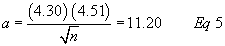
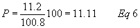
3.6 Since the facility did not meet the specific DQO criterion, they ran three more test runs.
| Run | CE |
|---|---|
| 4 | 93.2 |
| 5 | 96.2 |
| 6 | 87.6 |
3.7 The calculations for Runs 1-6 are made as follows using Equations 7 and 8:
n = 6 t0.975 = 2.57 xavg = 96.6 s = 6.11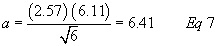
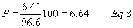
3.8 The facility still did not meet the specific DQO criterion. They ran three more test runs with the following results:
| Run | CE |
|---|---|
| 7 | 92.9 |
| 8 | 98.3 |
| 9 | 91.0 |
3.9 The calculations for Runs 1-9 are made as follows using Equations 9 and 10:
n = 9 t0.975 = 2.31 xavg = 95.7 s = 5.33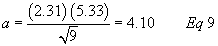
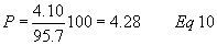
3.10 Based on these results, the specific DQO criterion is satisfied. Since all of the general criteria were also satisfied, the average CE from the nine test runs can be used to determine compliance.
4. Lower Confidence Limit Approach4.1 The purpose of the LCL approach is to provide sources, that may be performing much better than their applicable regulatory requirement, a screening option by which they can demonstrate compliance. The approach uses less precise methods and avoids additional test runs which might otherwise be needed to meet the specific DQO criterion while still being assured of correctly demonstrating compliance. It is designed to reduce “false positive” or so called “Type II errors” which may erroneously indicate compliance where more variable test methods are employed. Because it encourages CE performance greater than that required in exchange for reduced compliance demonstration burden, the sources that successfully use the LCL approach could produce emission reductions beyond allowable emissions. Thus, it could provide additional benefits to the environment as well.
4.2 The LCL approach compares the 80 percent (two-sided) LCL for the mean measured CE value to the applicable CE regulatory requirement. In addition to the general criteria described in section 2, the specific LCL criteria are that either the LCL be greater than or equal to the applicable CE regulatory requirement or that the specific DQO criterion is met. A more detailed description of the LCL approach follows:
4.3 A source conducts an initial series of at least three runs. The owner or operator may choose to conduct additional test runs during the initial test if desired.
4.4 If all of the general criteria are met and the specific DQO criterion is met, then the average CE value is used to determine compliance.
4.5 If the data meet all of the general criteria, but do not meet the specific DQO criterion; and the average CE, using all valid test runs, is above 100 percent then the test sequence cannot be used to calculate the LCL. At this point the facility has the option of (a) conducting more test runs in hopes of meeting the DQO or of bringing the average CE for all test runs below 100 percent so the LCL can be used or (b) discarding all previous test data and retesting.
4.6 The purpose of the requirement in Section 4.5 is to protect against protocols and test methods which may be inherently biased high. This is important because it is impossible to have an actual CE greater than 100 percent and the LCL approach only looks at the lower end variability of the test results. This is different from the DQO which allows average CE values up to 105 percent because the DQO sets both upper and lower limits on test variability.
4.7 If at any point during testing the results meet the DQO, the average CE can be used for demonstrating compliance with the applicable regulatory requirement. Similarly, if the average CE is below 100 percent then the LCL can be used for demonstrating compliance with the applicable regulatory requirement without regard to the DQO.
4.8 The LCL is calculated at an 80 percent (two-sided) confidence level as follows using Equation 11:
Where: LC1 = LCL at an 80-percent (two-sided) confidence level. n = Number of valid test runs. s = Sample standard deviation. t0.90 = t-value at the 80-percent (two-sided) confidence level (see Table A-1). xavg = Average measured CE value (calculated from all valid test runs).4.9 The resulting LC1 is compared to the applicable CE regulatory requirement. If LC1 exceeds (i.e., is higher than) the applicable regulatory requirement, then a facility is in initial compliance. However, if the LC1 is below the CE requirement, then the facility must conduct additional test runs. After this point the test results will be evaluated not only looking at the LCL, but also the DQO of ±5 percent of the mean at a 95 percent confidence level. If the test results with the additional test runs meet the DQO before the LCL exceeds the applicable CE regulatory requirement, then the average CE value will be compared to the applicable CE regulatory requirement for determination of compliance.
4.10 If there is no specific CE requirement in the applicable regulation, then the applicable CE regulatory requirement is determined based on the applicable regulation and an acceptable destruction efficiency test. If the applicable regulation requires daily compliance and the latest CE compliance demonstration was made using the LCL approach, then the calculated LC1 will be the highest CE value which a facility is allowed to claim until another CE demonstration test is conducted. This last requirement is necessary to assure both sufficiently reliable test results in all circumstances and the potential environmental benefits referenced above.
4.11 An example of calculating the LCL is shown below. Facility B's applicable regulatory requirement is 85 percent CE. Facility B conducted a CE test using a traditional liquid/gas mass balance and submitted the following results and the calculation shown in Equation 12:
| Run | CE |
|---|---|
| 1 | 94.2 |
| 2 | 97.6 |
| 3 | 90.5 |
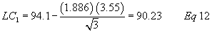
4.12 Since the LC1 of 90.23 percent is above the applicable regulatory requirement of 85 percent then the facility is in compliance. The facility must continue to accept the LC1 of 90.23 percent as its CE value until a new series of valid tests is conducted. (The data generated by Facility B do not meet the specific DQO criterion.)
5. Recommended Reporting for Alternative CE Protocols5.1 If a facility chooses to use alternative CE protocols and test methods that satisfy either the DQO or LCL and the additional criteria in section 4., the following information should be submitted with each test report to the appropriate regulatory agency:
1. A copy of all alternative test methods, including any changes to the EPA reference methods, QA/QC procedures and calibration procedures.
2. A table with information on each liquid sample, including the sample identification, where and when the sample was taken, and the VOC content of the sample;
3. The coating usage for each test run (for protocols in which the liquid VOC input is to be determined);
4. The quantity of captured VOC measured for each test run;
5. The CE calculations and results for each test run;
6. The DQO or LCL calculations and results; and
7. The QA/QC results, including information on calibrations (e.g., how often the instruments were calibrated, the calibration results, and information on calibration gases, if applicable).
6. Recommended Recordkeeping for Alternative CE Protocols.6.1 A record should be kept at the facility of all raw data recorded during the test in a suitable form for submittal to the appropriate regulatory authority upon request.
[61 FR 27140, May 30, 1996, as amended at 71 FR 29804, May 24, 2006]Table 1 to Subpart LL of Part 63 - Potline TF Limits for Emission Averaging
40:12.0.1.1.1.12.18.18.36 :
Table 1 to Subpart LL of Part 63 - Potline TF Limits for Emission Averaging| Type | Semiannual TF limit (lb/ton) [for given number of potlines] | ||||||
|---|---|---|---|---|---|---|---|
| 2 lines | 3 lines | 4 lines | 5 lines | 6 lines | 7 lines | 8 lines | |
| CWPB1 | 1.7 | 1.6 | 1.5 | 1.5 | 1.4 | 1.4 | 1.4 |
| CWPB2 | 2.9 | 2.8 | 2.7 | 2.7 | 2.6 | 2.6 | 2.6 |
| CWPB3 | 2.3 | 2.2 | 2.2 | 2.1 | 2.1 | 2.1 | 2.1 |
| SWPB | 1.4 | 1.3 | 1.3 | 1.2 | 1.2 | 1.2 | 1.2 |
| VSS2 | 2.6 | 2.5 | 2.5 | 2.4 | 2.4 | 2.4 | 2.4 |
Table 2 to Subpart LL of Part 63 - Potline POM Limits for Emission Averaging
40:12.0.1.1.1.12.18.18.37 :
Table 2 to Subpart LL of Part 63 - Potline POM Limits for Emission Averaging| Type | Semiannual POM limit (lb/ton) [for given number of potlines] | ||||||
|---|---|---|---|---|---|---|---|
| 2 lines | 3 lines | 4 lines | 5 lines | 6 lines | 7 lines | 8 lines | |
| CWPB1 | 1 | 0.9 | 0.9 | 0.9 | 0.8 | 0.8 | 0.8 |
| CWPB2 | 11.6 | 11.2 | 10.8 | 10.8 | 10.4 | 10.4 | 10.4 |
| CWPB3 | 2.5 | 2.4 | 2.4 | 2.3 | 2.3 | 2.3 | 2.3 |
| SWPB | 14.8 | 13.8 | 13.8 | 13.8 | 13.8 | 13.8 | 13.8 |
| VSS2 | 1.7 | 1.6 | 1.5 | 1.5 | 1.4 | 1.4 | 1.4 |
Table 3 to Subpart LL of Part 63 - Potline PM Limits for Emission Averaging
40:12.0.1.1.1.12.18.18.38 :
Table 3 to Subpart LL of Part 63 - Potline PM Limits for Emission Averaging| Type | Semiannual PM limit (lb/ton) [for given number of potlines] | ||||||
|---|---|---|---|---|---|---|---|
| 2 lines | 3 lines | 4 lines | 5 lines | 6 lines | 7 lines | 8 lines | |
| CWPB1 | 6.1 | 6.1 | 5.3 | 5.3 | 5.0 | 5.0 | 5.0 |
| CWPB2 | 10.6 | 10.3 | 9.9 | 9.9 | 9.5 | 9.5 | 9.5 |
| CWPB3 | 18.4 | 17.6 | 17.6 | 16.8 | 16.8 | 16.8 | 16.8 |
| SWPB | 4.3 | 3.9 | 3.9 | 3.7 | 3.7 | 3.7 | 3.7 |
| VSS2 | 25 | 24.1 | 24.1 | 23.1 | 23.1 | 23.1 | 23.1 |
Table 4 to Subpart LL of Part 63 - Anode Bake Furnace Limits for Emission Averaging
40:12.0.1.1.1.12.18.18.39 :
Table 4 to Subpart LL of Part 63 - Anode Bake Furnace Limits for Emission Averaging| Number of furnaces | Emission limit (lb/ton of anode) | ||
|---|---|---|---|
| TF | POM | PM | |
| 2 | 0.11 | 0.17 | 0.11 |
| 3 | 0.09 | 0.17 | 0.091 |
| 4 | 0.077 | 0.17 | 0.076 |
| 5 | 0.07 | 0.17 | 0.071 |
Appendix A to Subpart LL of Part 63 - Applicability of General Provisions
40:12.0.1.1.1.12.18.18.40 : Appendix A
Appendix A to Subpart LL of Part 63 - Applicability of General Provisions| Reference section(s) | Requirement | Applies to subpart LL | Comment |
|---|---|---|---|
| 63.1(a)(1) through (4) | General Applicability | Yes | |
| 63.1(a)(5) | No | [Reserved]. | |
| 63.1(a)(6) | Yes | ||
| 63.1(a)(7) through (9) | No | [Reserved]. | |
| 63.1(a)(10) through (12) | Yes | ||
| 63.1(b)(1) through (3) | Initial Applicability Determination | Yes | (b)(2) Reserved. |
| 63.1(c)(1) | Applicability after standard Established | Yes | |
| 63.1(c)(2) | Yes | Area sources are not subject to this subpart. | |
| 63.1(c)(3) and (4) | No | [Reserved]. | |
| 63.1(c)(5) | Yes | ||
| 63.1(c)(6) | Reclassification | Yes | |
| 63.1(d) | No | [Reserved]. | |
| 63.1(e) | Applicability of Permit Program | Yes | |
| 63.2 | Definitions | Yes | Reconstruction defined in § 63.842. |
| 63.3 | Units and Abbreviations | Yes | |
| 63.4(a)(1) and (2) | Prohibited activities | Yes | |
| 63.4(a)(3) through (5) | No | [Reserved]. | |
| 63.4(b) and (c) | Circumvention/Severability | Yes | |
| 63.5(a) | Construction/Reconstruction Applicability | Yes | |
| 63.5(b)(1) | Existing, New, Reconstructed Sources Requirements | Yes | |
| 63.5(b)(2) | No | [Reserved]. | |
| 63.5(b)(3) and (4) | Yes | ||
| 63.5(b)(5) | No | [Reserved]. | |
| 63.5(b)(6) | Yes | ||
| 63.5(c) | No | [Reserved]. | |
| 63.5(d) | Application for Approval of Construction/Reconstruction | Yes | |
| 63.5(e) | Approval of Construction/Reconstruction | Yes | |
| 63.5(f) | Approval of Construction/Reconstruction Based on State Review | Yes | |
| 63.6(a) | Compliance with Standards and Maintenance Applicability | Yes | |
| 63.6(b)(1) through (5) | New and Reconstructed Source Dates | Yes | See § 847(a)(6) and (7). |
| 63.6(b)(6) | No | [Reserved]. | |
| 63.6(b)(7) | Yes | ||
| 63.6(c)(1) | Existing Source Dates | No | See § 847(a). |
| 63.6(c)(2) | Yes | ||
| 63.6(c)(3) and (4) | No | [Reserved]. | |
| 63.6(c)(5) | Yes | ||
| 63.6(d) | No | [Reserved]. | |
| 63.6(e)(1)(i) | No | See §§ 63.843(f) and 63.844(f) for general duty requirement. | |
| 63.6(e)(1)(ii) | No | ||
| 63.6(e)(1)(iii) | Yes | ||
| 63.6(e)(2) | No | [Reserved]. | |
| 63.6(e)(3) | Startup, Shutdown and Malfunction Plan | No | |
| 63.6(f)(1) | Compliance with Emissions Standards | No | |
| 63.6(f)(2) | Methods/Finding of Compliance | Yes | |
| 63.6(g) | Alternative Standard | Yes | |
| 63.6(h) | Compliance with Opacity/VE Standards | Only in § 63.845 | Opacity standards applicable only when incorporating the NSPS requirements under § 63.845. |
| 63.6(i)(1) through (14) | Extension of Compliance | Yes | |
| 63.6(i)(15) | No | [Reserved]. | |
| 63.6(i)(16) | Yes | ||
| 63.6(j) | Exemption from Compliance | Yes | |
| 63.7(a) | Performance Test Requirements Applicability | Yes | |
| 63.7(b) | Notification | Yes | |
| 63.7(c) | Quality Assurance/Test Plan | Yes | |
| 63.7(d) | Testing facilities | Yes | |
| 63.7(e)(1) | Conduct of Tests | No | See § 63.847(d). |
| 63.7(e)(2) through (4) | Yes | ||
| 63.7(f), (g), (h) | Alternative Test Method | Yes | |
| 63.8(a)(1) and (2) | Monitoring Requirements Applicability | Yes | |
| 63.8(a)(3) | No | [Reserved]. | |
| 63.8(b) | Conduct of Monitoring | Yes | |
| 63.8(c)(1)(i) | No | See §§ 63.843(f) and 63.844(f) for general duty requirement. | |
| 63.8(c)(1)(ii) | Yes | ||
| 63.8(c)(1)(iii) | No | ||
| 63.8(c)(2) through (d)(2) | Yes | ||
| 63.8(d)(3) | Yes, except for last sentence | ||
| 63.8(e) through (g) | Yes | ||
| 63.9(a) | Notification Requirements Applicability | Yes | |
| 63.9(b) | Initial Notifications | Yes | Notification of re-start specified in § 63.850(a)(9). |
| 63.9(c) | Request for Compliance Extension | Yes | |
| 63.9(d) | New Source Notification for Special Compliance Requirements | Yes | |
| 63.9(e) | Notification of Performance Test | No | |
| 63.9(f) | Notification of VE/Opacity Test | No | |
| 63.9(g) | Additional CMS Notifications | No | |
| 63.9(h)(1) through (3) | Notification of Compliance Status | Yes | |
| 63.9(h)(4) | No | [Reserved]. | |
| 63.9(h)(5) and (6) | Yes | ||
| 63.9(i) | Adjustment of Deadlines | Yes | |
| 63.9(j) | Change in Previous Information | Yes | |
| 63.9(k) | Electronic reporting procedures | Yes | Only as specified in § 63.9(j). |
| 63.10(a) | Recordkeeping/Reporting Applicability | Yes | |
| 63.10(b)(1) | General Recordkeeping Requirements | Yes | |
| 63.10(b)(2)(i) | No | ||
| 63.10(b)(2)(ii) | No | See §§ 63.850(e)(4)(xvi) and (xvii) for recordkeeping of occurrence and duration of malfunctions and recordkeeping of actions taken during malfunction. | |
| 63.10(b)(2)(iii) | Yes | ||
| 63.10(b)(2)(iv) and (v) | No | ||
| 63.10(b)(2)(vi) through (xiv) | Yes | ||
| 63.(10)(b)(3) | Yes | ||
| 63.10(c)(1) through (9) | Yes | ||
| 63.10(c)(10) and (11) | No | See §§ 63.850(e)(4)(xvi) and (xvii) for recordkeeping of malfunctions. | |
| 63.10(c)(12) through (14) | Yes | ||
| 63.10(c)(15) | No | ||
| 63.10(d)(1) | General Reporting Requirements | Yes | |
| 63.10(d)(2) | No | See § 63.850(b). | |
| 63.10(d)(3) and (4) | Yes | ||
| 63.10(d)(5) | Startup-Shutdown and Malfunction Reports | No | See § 63.850(d)(2) for reporting of malfunctions. |
| 63.10(e) and (f) | Additional CMS Reports and Recordkeeping/Reporting Waiver | Yes | |
| 63.11 | Control Device/work practices requirements Applicability | No | |
| 63.12 | State Authority and Delegations | Yes | |
| 63.13 | Addresses | Yes | |
| 63.14 | Incorporation by Reference | Yes | |
| 63.15 | Information Availability/Confidentiality | Yes | |
| 63.16 | Performance Track Provisions | No |
Table 1 to Subpart MM of Part 63 - General Provisions Applicability to Subpart MM
40:12.0.1.1.1.13.18.10.41 :
Table 1 to Subpart MM of Part 63 - General Provisions Applicability to Subpart MM| General provisions reference |
Summary of requirements | Applies to subpart MM |
Explanation |
|---|---|---|---|
| 63.1(a)(1) | General applicability of the General Provisions | Yes | Additional terms defined in § 63.861; when overlap between subparts A and MM of this part, subpart MM takes precedence. |
| 63.1(a)(2)-(14) | General applicability of the General Provisions | Yes | |
| 63.1(b)(1) | Initial applicability determination | No | Subpart MM specifies the applicability in § 63.860. |
| 63.1(b)(2) | Title V operating permit - see 40 CFR part 70 | Yes | All major affected sources are required to obtain a title V permit. |
| 63.1(b)(3) | Record of the applicability determination | No | All affected sources are subject to subpart MM according to the applicability definition of subpart MM. |
| 63.1(c)(1) | Applicability of subpart A of this part after a relevant standard has been set | Yes | Subpart MM clarifies the applicability of each paragraph of subpart A of this part to sources subject to subpart MM. |
| 63.1(c)(2) | Title V permit requirement | Yes | All major affected sources are required to obtain a title V permit. There are no area sources in the pulp and paper mill source category. |
| 63.1(c)(3) | [Reserved] | No | |
| 63.1(c)(4) | Requirements for existing source that obtains an extension of compliance | Yes | |
| 63.1(c)(5) | Notification requirements for an area source that increases HAP emissions to major source levels | Yes | |
| 63.1(c)(6) | Reclassification | Yes | |
| 63.1(d) | [Reserved] | No | |
| 63.1(e) | Applicability of permit program before a relevant standard has been set | Yes | |
| 63.2 | Definitions | Yes | Additional terms defined in § 63.861; when overlap between subparts A and MM of this part occurs, subpart MM takes precedence. |
| 63.3 | Units and abbreviations | Yes | |
| 63.4 | Prohibited activities and circumvention | Yes | |
| 63.5(a) | Construction and reconstruction - applicability | Yes | |
| 63.5(b)(1) | Upon construction, relevant standards for new sources | Yes | |
| 63.5(b)(2) | [Reserved] | No | |
| 63.5(b)(3) | New construction/reconstruction | Yes | |
| 63.5(b)(4) | Construction/reconstruction notification | Yes | |
| 63.5(b)(5) | Construction/reconstruction compliance | Yes | |
| 63.5(b)(6) | Equipment addition or process change | Yes | |
| 63.5(c) | [Reserved] | No | |
| 63.5(d) | Application for approval of construction/reconstruction | Yes | |
| 63.5(e) | Construction/reconstruction approval | Yes | |
| 63.5(f) | Construction/reconstruction approval based on prior State preconstruction review | Yes | |
| 63.6(a)(1) | Compliance with standards and maintenance requirements - applicability | Yes | |
| 63.6(a)(2) | Requirements for area source that increases emissions to become major | Yes | |
| 63.6(b) | Compliance dates for new and reconstructed sources | Yes | |
| 63.6(c) | Compliance dates for existing sources | Yes, except for sources granted extensions under 63.863(c) | Subpart MM specifically stipulates the compliance schedule for existing sources. |
| 63.6(d) | [Reserved] | No | |
| 63.6(e)(1)(i) | General duty to minimize emissions | No | See § 63.860(d) for general duty requirement. |
| 63.6(e)(1)(ii) | Requirement to correct malfunctions ASAP | No | |
| 63.6(e)(1)(iii) | Operation and maintenance requirements enforceable independent of emissions limitations | Yes | |
| 63.6(e)(2) | [Reserved] | No | |
| 63.6(e)(3) | Startup, shutdown, and malfunction plan (SSMP) | No | |
| 63.6(f)(1) | Compliance with nonopacity emissions standards except during SSM | No | |
| 63.6(f)(2)-(3) | Methods for determining compliance with nonopacity emissions standards | Yes | |
| 63.6(g) | Compliance with alternative nonopacity emissions standards | Yes | |
| 63.6(h)(1) | Compliance with opacity and visible emissions (VE) standards except during SSM | No | |
| 63.6(h)(2)-(9) | Compliance with opacity and VE standards | Yes | Subpart MM does not contain any opacity or VE standards; however, § 63.864 specifies opacity monitoring requirements. |
| 63.6(i) | Extension of compliance with emissions standards | Yes | |
| 63.6(j) | Exemption from compliance with emissions standards | Yes | |
| 63.7(a)(1) | Performance testing requirements - applicability | Yes | |
| 63.7(a)(2) | Performance test dates | Yes | |
| 63.7(a)(3) | Performance test requests by Administrator under CAA section 114 | Yes | |
| 63.7(a)(4) | Notification of delay in performance testing due to force majeure | Yes | |
| 63.7(b)(1) | Notification of performance test | Yes | |
| 63.7(b)(2) | Notification of delay in conducting a scheduled performance test | Yes | |
| 63.7(c) | Quality assurance program | Yes | |
| 63.7(d) | Performance testing facilities | Yes | |
| 63.7(e)(1) | Conduct of performance tests | No | See § 63.865. |
| 63.7(e)(2)-(3) | Conduct of performance tests | Yes | |
| 63.7(e)(4) | Testing under section 114 | Yes | |
| 63.7(f) | Use of an alternative test method | Yes | |
| 63.7(g) | Data analysis, recordkeeping, and reporting | Yes | |
| 63.7(h) | Waiver of performance tests | Yes | § 63.865(c)(1) specifies the only exemption from performance testing allowed under subpart MM. |
| 63.8(a)(1) | Monitoring requirements - applicability | Yes | See § 63.864. |
| 63.8(a)(2) | Performance Specifications | Yes | |
| 63.8(a)(3) | [Reserved] | No | |
| 63.8(a)(4) | Monitoring with flares | No | The use of flares to meet the standards in subpart MM is not anticipated. |
| 63.8(b)(1) | Conduct of monitoring | Yes | See § 63.864. |
| 63.8(b)(2)-(3) | Specific requirements for installing and reporting on monitoring systems | Yes | |
| 63.8(c)(1) | Operation and maintenance of CMS | Yes | See § 63.864. |
| 63.8(c)(1)(i) | General duty to minimize emissions and CMS operation | No | |
| 63.8(c)(1)(ii) | Reporting requirements for SSM when action not described in SSMP | Yes | |
| 63.8(c)(1)(iii) | Requirement to develop SSM plan for CMS | No | |
| 63.8(c)(2)-(3) | Monitoring system installation | Yes | |
| 63.8(c)(4) | CMS requirements | Yes | |
| 63.8(c)(5) | Continuous opacity monitoring system (COMS) minimum procedures | Yes | |
| 63.8(c)(6) | Zero and high level calibration check requirements | Yes | |
| 63.8(c)(7)-(8) | Out-of-control periods | Yes | |
| 63.8(d)(1)-(2) | CMS quality control program | Yes | See § 63.864. |
| 63.8(d)(3) | Written procedures for CMS | No | See § 63.864(f). |
| 63.8(e)(1) | Performance evaluation of CMS | Yes | |
| 63.8(e)(2) | Notification of performance evaluation | Yes | |
| 63.8(e)(3) | Submission of site-specific performance evaluation test plan | Yes | |
| 63.8(e)(4) | Conduct of performance evaluation and performance evaluation dates | Yes | |
| 63.8(e)(5) | Reporting performance evaluation results | Yes | |
| 63.8(f) | Use of an alternative monitoring method | Yes | |
| 63.8(g) | Reduction of monitoring data | Yes | |
| 63.9(a) | Notification requirements - applicability and general information | Yes | |
| 63.9(b) | Initial notifications | Yes | |
| 63.9(c) | Request for extension of compliance | Yes | |
| 63.9(d) | Notification that source subject to special compliance requirements | Yes | |
| 63.9(e) | Notification of performance test | Yes | |
| 63.9(f) | Notification of opacity and VE observations | Yes | Subpart MM does not contain any opacity or VE standards; however, § 63.864 specifies opacity monitoring requirements. |
| 63.9(g)(1) | Additional notification requirements for sources with CMS | Yes | |
| 63.9(g)(2) | Notification of compliance with opacity emissions standard | Yes | Subpart MM does not contain any opacity or VE emissions standards; however, § 63.864 specifies opacity monitoring requirements. |
| 63.9(g)(3) | Notification that criterion to continue use of alternative to relative accuracy testing has been exceeded | Yes | |
| 63.9(h) | Notification of compliance status | Yes | |
| 63.9(i) | Adjustment to time periods or postmark deadlines for submittal and review of required communications | Yes | |
| 63.9(j) | Change in information already provided | Yes | |
| 63.9(k) | Electronic reporting procedures | Yes | Only as specified in § 63.9(j). |
| 63.10(a) | Recordkeeping requirements - applicability and general information | Yes | See § 63.866. |
| 63.10(b)(1) | Records retention | Yes | |
| 63.10(b)(2)(i) | Recordkeeping of occurrence and duration of startups and shutdowns | No | |
| 63.10(b)(2)(ii) | Recordkeeping of failures to meet a standard | No | See § 63.866(d) for recordkeeping of (1) date, time and duration; (2) listing of affected source or equipment, and an estimate of the quantity of each regulated pollutant emitted over the standard; and (3) actions to minimize emissions and correct the failure. |
| 63.10(b)(2)(iii) | Maintenance records | Yes | |
| 63.10(b)(2)(iv)-(v) | Actions taken to minimize emissions during SSM | No | |
| 63.10(b)(2)(vi) | Recordkeeping for CMS malfunctions | Yes | |
| 63.10(b)(2)(vii)-(xiv) | Other CMS requirements | Yes | |
| 63.10(b)(3) | Records retention for sources not subject to relevant standard | Yes | Applicability requirements are given in § 63.860. |
| 63.10(c)(1)-(14) | Additional recordkeeping requirements for sources with CMS | Yes | |
| 63.10(c)(15) | Use of SSM plan | No | |
| 63.10(d)(1) | General reporting requirements | Yes | |
| 63.10(d)(2) | Reporting results of performance tests | Yes | |
| 63.10(d)(3) | Reporting results of opacity or VE observations | Yes | Subpart MM does not include any opacity or VE standards; however, § 63.864 specifies opacity monitoring requirements. |
| 63.10(d)(4) | Progress reports | Yes | |
| 63.10(d)(5)(i) | Periodic startup, shutdown, and malfunction reports | No | See § 63.867(c)(3) for malfunction reporting requirements. |
| 63.10(d)(5)(ii) | Immediate startup, shutdown, and malfunction reports | No | See § 63.867(c)(3) for malfunction reporting requirements. |
| 63.10(e)(1) | Additional reporting requirements for sources with CMS - General | Yes | |
| 63.10(e)(2) | Reporting results of CMS performance evaluations | Yes | |
| 63.10(e)(3)(i)-(iv) | Requirement to submit excess emissions and CMS performance report and/or summary report and frequency of reporting | No | § 63.867(c)(1) and (3) require submittal of the excess emissions and CMS performance report and/or summary report on a semiannual basis. |
| 63.10(e)(3)(v) | General content and submittal dates for excess emissions and monitoring system performance reports | Yes | |
| 63.10(e)(3)(vi) | Specific summary report content | No | § 63.867(c)(1) specifies the summary report content. |
| 63.10(e)(3)(vii)-(viii) | Conditions for submitting summary report versus detailed excess emission report | No | § 63.867(c)(1) and (3) specify the conditions for submitting the summary report or detailed excess emissions and CMS performance report. |
| 63.10(e)(4) | Reporting continuous opacity monitoring system data produced during a performance test | Yes | |
| 63.10(f) | Waiver of recordkeeping and reporting requirements | Yes | |
| 63.11 | Control device requirements for flares | No | The use of flares to meet the standards in subpart MM is not anticipated. |
| 63.12 | State authority and delegations | Yes | |
| 63.13 | Addresses of State air pollution control agencies and EPA Regional Offices | Yes | |
| 63.14 | Incorporations by reference | Yes | |
| 63.15 | Availability of information and confidentiality | Yes | |
| 63.16 | Requirements for Performance Track member facilities | Yes |
Table 1 to Subpart NN of Part 63 - Applicability of General Provisions (40 CFR Part 63, Subpart A) to Subpart NN
40:12.0.1.1.1.14.18.11.42 :
Table 1 to Subpart NN of Part 63 - Applicability of General Provisions (40 CFR Part 63, Subpart A) to Subpart NN| General provisions citation |
Requirement | Applies to subpart NN | Explanation |
|---|---|---|---|
| § 63.1(a)(1)-(5) | Applicability | Yes | |
| § 63.1(a)(6) | Yes | ||
| § 63.1(a)(7)-(9) | No | [Reserved]. | |
| § 63.1(a)(10)-(12) | Yes | ||
| § 63.1(b)(1) | Initial Applicability Determination | Yes | |
| § 63.1(b)(2) | No | [Reserved]. | |
| § 63.1(b)(3) | Yes | ||
| § 63.1(c)(1)-(2) | Yes | ||
| § 63.1(c)(3)-(4) | No | [Reserved]. | |
| § 63.1(c)(5)-(e) | Yes | ||
| § 63.2 | Definitions | Yes | Additional definitions in § 63.881. |
| § 63.3 | Units and Abbreviations | Yes | |
| § 63.4(a)(1)-(2) | Prohibited Activities | Yes | |
| § 63.4(a)(3)-(5) | No | [Reserved]. | |
| § 63.4(b)-(c) | Yes | ||
| § 63.5(a)-(b)(2) | Construction/Reconstruction Applicability | Yes | |
| § 63.5(b)(3)-(4) | Yes | ||
| § 63.5(b)(5) | No | [Reserved]. | |
| § 63.5(b)(6) | Yes | ||
| § 63.5(c) | No | [Reserved]. | |
| § 63.5(d) | Application for Approval of Construction/Reconstruction | Yes | |
| § 63.5(e) | Approval of Construction/Reconstruction | Yes | |
| § 63.5(f) | Approval of Construction/Reconstruction Based on State Review | Yes | |
| § 63.6(a)-(d) | Compliance with Standards and Maintenance Requirements | Yes | |
| § 63.6(e)(1)(i) | General Duty to Minimize Emissions | No | See § 63.882 for general duty requirements. |
| § 63.6(e)(1)(ii) | Requirement to Correct Malfunctions As Soon As Possible | No | |
| § 63.6(e)(1)(iii) | Yes | ||
| § 63.6(e)(2) | No | [Reserved]. | |
| § 63.6(e)(3) | Startup, Shutdown, and Malfunction (SSM) Plan | No | Startups and shutdowns addressed in § 63.888. |
| § 63.6(f)(1) | SSM Exemption | No | |
| § 63.6(f)(2)-(3) | Methods for Determining Compliance | Yes | |
| § 63.6(g) | Use of an Alternative Nonopacity Emission | Yes | |
| § 63.6(h)(1) | SSM Exemption | No | |
| § 63.6(h)(2)-(j) | Yes | ||
| § 63.7(a)-(d) | Yes | § 63.884 has specific requirements. | |
| § 63.7(e)(1) | Performance Testing | No | See § 63.882. |
| § 63.7(e)(2)-(4) | Yes | ||
| § 63.7(f) | Alternative Test Method | Yes | |
| § 63.7(g)(1) | Data Analysis | Yes | |
| § 63.7(g)(2) | No | [Reserved]. | |
| § 63.7(g)(3) | Yes | ||
| § 63.7(h) | Waiver of Performance Test | Yes | |
| § 63.8(a)-(b) | Monitoring Requirements | Yes | |
| § 63.8(c)(1)(i) | General Duty to Minimize Emissions and CMS Operation | No | See § 63.882(b) for general duty requirement. |
| § 63.8(c)(1)(ii) | Yes | ||
| § 63.8(c)(1)(iii) | Requirement to Develop SSM Plan for CMS | No | |
| § 63.8(c)(2)-(d)(2) | Yes | ||
| § 63.8(d)(3) | Written Procedures for CMS | Yes, except for last sentence, which refers to SSM plan. SSM plans are not required | |
| § 63.8(e)-(g) | Yes | ||
| § 63.9(a) | Notification Requirements | Yes | |
| § 63.9(b)(1)-(2) | Initial Notifications | Yes | |
| § 63.9(b)(3) | No | [Reserved]. | |
| § 63.9(b)(4)-(5) | Yes | ||
| § 63.9(c)-(j) | Yes | ||
| § 63.10(a) | Recordkeeping and Reporting-Requirements | Yes | |
| § 63.10(b)(1) | General Recordkeeping Requirements | Yes | |
| § 63.10(b)(2)(i) | Recordkeeping of Occurrence and Duration of Startups and Shutdowns | No | |
| § 63.10(b)(2)(ii) | Recordkeeping of Malfunctions | No | See § 63.886 for recordkeeping of occurrence and duration of malfunctions and recordkeeping of actions taken during malfunction. |
| § 63.10(b)(2)(iii) | Maintenance Records | Yes | |
| § 63.10(b)(2)(iv)-(v) | Actions Taken to Minimize Emissions During SSM | No | |
| § 63.10(b)(2)(vi) | Recordkeeping for CMS Malfunctions | Yes | |
| § 63.10(b)(2)(vii)-(xiv) | Other CMS Requirements | Yes | |
| § 63.10(b)(3) | Recordkeeping Requirement for Applicability Determinations | Yes | |
| § 63.10(c)(1)-(6) | Additional Recordkeeping Requirements for Sources with CMS | Yes | |
| § 63.10(c)(7)-(8) | Additional Recordkeeping Requirements for CMS - Identifying Exceedances and Excess Emissions | Yes | |
| § 63.10(c)(9) | No | [Reserved]. | |
| § 63.10(c)(10)-(11) | No | See § 63.886 for recordkeeping of malfunctions. | |
| § 63.10(c)(12)-(14) | Yes | ||
| § 63.10(c)(15) | Use of SSM Plan | No | |
| § 63.10(d)(1)-(4) | General Reporting Requirements | Yes | |
| § 63.10(d)(5) | SSM Reports | No | See § 63.886(c)(2) for reporting of malfunctions. |
| § 63.10(e)-(f) | Additional CMS Reports Excess Emission/CMS Performance Reports COMS Data Reports Recordkeeping/Reporting Waiver | Yes | |
| § 63.11(a)-(b) | Control Device Requirements Applicability Flares | No | Flares will not be used to comply with the emissions limits. |
| § 63.11(c) | Alternative Work Practice for Monitoring Equipment for Leaks | Yes | |
| § 63.11(d) | Alternative Work Practice Standard | Yes | |
| § 63.11(e) | Alternative Work Practice Requirements | Yes | |
| § 63.12 | State Authority and Delegations | Yes | |
| § 63.13 | Addresses | Yes | |
| § 63.14 | Incorporation by Reference | Yes | |
| § 63.15 | Information Availability/Confidentiality | Yes | |
| § 63.16 | Performance Track Provisions | Yes |
Table 1 to Subpart UU of Part 63 - Batch Processes Monitoring Frequency For Equipment Other Than Connectors
40:12.0.1.1.1.21.18.22.43 :
Table 1 to Subpart UU of Part 63 - Batch Processes Monitoring Frequency For Equipment Other Than Connectors| Operating
time (% of year) |
Equivalent continuous process monitoring frequency time in use | ||
|---|---|---|---|
| Monthly | Quarterly | Semiannually | |
| 0 to <25% | Quarterly | Annually | Annually. |
| 25 to <50% | Quarterly | Semiannually | Annually. |
| 50 to <75% | Bimonthly | Three times | Semiannually. |
| 75 to 100% | Monthly | Quarterly | Semiannually. |
Table 1 to Subpart XX of Part 63 - Hazardous Air Pollutants
40:12.0.1.1.1.24.29.19.44 :
Table 1 to Subpart XX of Part 63 - Hazardous Air Pollutants| Hazardous air pollutant | CAS No. |
|---|---|
| Benzene | 71432 |
| 1,3-Butadiene | 106990 |
| Cumene | 98828 |
| Ethyl benzene | 100414 |
| Hexane | 110543 |
| Naphthalene | 91203 |
| Styrene | 100425 |
| Toluene | 108883 |
| o-Xylene | 95476 |
| m-Xylene | 108383 |
| p-Xylene | 106423 |
Table 2 to Subpart XX of Part 63 - Requirements of 40 CFR Part 61, Subpart FF, Not Included in the Requirements for This Subpart and Alternate Requirements
40:12.0.1.1.1.24.29.19.45 :
Table 2 to Subpart XX of Part 63 - Requirements of 40 CFR Part 61, Subpart FF, Not Included in the Requirements for This Subpart and Alternate Requirements| If the total annual benzene quantity for waste from your facility is * * * | Do not comply with: | Instead, comply with: |
|---|---|---|
| 1. Less than 10 Mg/yr | 40 CFR 61.340 | § 63.1093. |
| 40 CFR 61.342(c)(3)(ii), (d), and (e) | There is no equivalent requirement. | |
| 40 CFR 61.342(f) | § 63.1096. | |
| 40 CFR 61.355(j) and (k) | There is no equivalent requirement. | |
| 40 CFR 61.356(b)(2)(ii), (b)(3) through (b)(5) | There is no equivalent requirement. | |
| The requirement to submit the information required in 40 CFR 61.357(a) to the Administrator within 90 days after January 7, 1993 | The requirement to submit the information required in 40 CFR 61.357(a) as part of the Initial Notification required in 40 CFR 63.1110(c). | |
| The requirement in 40 CFR 61.357(d) to submit the information in 40 CFR 61.357(d)(1) and (d)(2) if the TAB quantity from your facility is equal to or greater than 10 Mg/yr | The requirement to submit the information in 40 CFR 61.357(d)(1) and (d)(2) for spent caustic, dilution steam blowdown, and continuous butadiene waste streams. | |
| The requirement in 40 CFR 61.357(d)(1) to submit the information required in 40 CFR 63.357(d)(1) to the Administrator within 90 days after January 7, 1993 | The requirement to submit the information required in 40 CFR 61.357(d)(1) as part of the Notification of Compliance Status required in 40 CFR 63.1110(d). | |
| 40 CFR 61.357(d)(3) through (d)(5) | There is no equivalent requirement. | |
| 2. Greater than or equal to 10 Mg/yr | 40 CFR 61.340 | § 63.1093. |
| 40 CFR 61.342(f) | § 63.1096. | |
| The requirement to submit the information required in 40 CFR 61.357(a) to the Administrator within 90 days after January 7, 1993 | The requirement to submit the information required in 40 CFR 61.357(a) as part of the Initial Notification required in 40 CFR 63.1110(c). | |
| The requirement in 40 CFR 61.357(d) to submit the information in 40 CFR 61.357(d)(1) and (d)(2) if the TAB quantity from your facility is equal to or greater than 10 Mg/yr | The requirement to submit the information in 40 CFR 61.357(d)(1) and (d)(2) as part of the Notification of Compliance Status required in 40 CFR 63.1110(d). |
Table 1 to Subpart CCC of Part 63 - Applicability of General Provisions (40 CFR Part 63, Subpart A) to Subpart CCC
40:12.0.1.1.1.27.29.14.46 :
Table 1 to Subpart CCC of Part 63 - Applicability of General Provisions (40 CFR Part 63, Subpart A) to Subpart CCC| Reference | Applies to Subpart CCC | Explanation |
|---|---|---|
| 63.1-63.5 | Yes. | |
| 63.6 (a)-(d) | Yes | |
| 63.6(e)(1)(i) | No | See § 63.1259(c) for general duty requirement. Any cross-reference to § 63.6(e)(1)(i) in any other general provision incorporated by reference shall be treated as a cross-reference to § 63.1259(c). |
| 63.6(e)(1)(ii) | No | |
| 63.6(e)(1)(iii) | Yes | |
| 63.6(e)(2) | No | Section reserved. |
| 63.6(e)(3) | No | |
| 63.6(f)(1) | No | |
| 63.6(f)(2)-(3) | Yes | |
| 63.6(g) | Yes | |
| 63.6(h) | No | Subpart CCC does not contain an opacity or visible emission standard. |
| 63.6 (i)-(j) | Yes. | |
| 63.7 | Yes | |
| 63.8(a)-(c) | Yes | |
| 63.8(d)(1)-(2) | Yes | |
| 63.8(d)(3) | Yes, except for last sentence | |
| 63.8(e)-(f) | Yes | |
| 63.9(j) | Yes | |
| 63.9(k) | Yes | Only as specified in § 63.9(j). |
| 63.10(a) | Yes | |
| 63.10(b)(1) | Yes | |
| 63.10(b)(2)(i) | No | |
| 63.10(b)(2)(ii) | No | See § 63.1265(a)(1) for recordkeeping of occurrence and duration of malfunctions. See § 63.1265(a)(4) for recordkeeping of actions taken during malfunction. Any cross-reference to § 63.10(b)(2)(ii) in any other general provision incorporated by reference shall be treated as a cross-reference to § 63.1265(a)(1). |
| 63.10(b)(2)(iii) | Yes | |
| 63.10(b)(2)(iv)-(b)(2)(v) | No | |
| 63.10(b)(2)(vi)-(b)(2)(xiv) | Yes | |
| 63.10(b)(3) | Yes | |
| 63.10(c)(1)-(9) | Yes | |
| 63.10(c)(10) | No | See § 63.1164(c) for reporting malfunctions. Any cross-reference to § 63.10(c)(10) in any other general provision incorporated by reference shall be treated as a cross-reference to § 63.1164(c). |
| 63.10(c)(11) | No | See § 63.1164(c) for reporting malfunctions. Any cross-reference to § 63.10(c)(11) in any other general provision incorporated by reference shall be treated as a cross-reference to § 63.1164(c). |
| 63.10(c)(12)-(c)(14) | Yes | |
| 63.10(c)(15) | No | |
| 63.10(d)(1)-(2) | Yes. | |
| 63.10(d)(3) | No | Subpart CCC does not contain an opacity or visible emission standard. |
| 63.10(d)(4) | Yes | |
| 63.10(d)(5) | No | |
| 63.10(e)-(f) | Yes. | |
| 63.11 | No | Subpart CCC does not require the use of flares. |
| 63.12-63.15 | Yes |
Table 1 to Subpart DDD of Part 63 - Applicability of General Provisions (40 CFR Part 63, Subpart A) to Subpart DDD of Part 63
40:12.0.1.1.1.28.35.25.47 :
Table 1 to Subpart DDD of Part 63 - Applicability of General Provisions (40 CFR Part 63, Subpart A) to Subpart DDD of Part 63| General provisions citation |
Requirement | Applies to subpart DDD? | Explanation |
|---|---|---|---|
| § 63.1(a)(1)-(6) | General Applicability | Yes | |
| § 63.1(a)(7)-(9) | No | [Reserved]. | |
| § 63.1(a)(10)-(12) | Yes | ||
| § 63.1(b)(1) | Initial Applicability Determination | Yes | |
| § 63.1(b)(2) | No | [Reserved]. | |
| § 63.1(b)(3) | Yes | ||
| § 63.1(c)(1)-(2) | Applicability After Standard Established | Yes | |
| § 63.1(c)(3)-(4) | No | [Reserved]. | |
| § 63.1(c)(5)-(e) | Yes | ||
| § 63.2 | Definitions | Yes | |
| § 63.3 | Units and Abbreviations | Yes | |
| § 63.4(a)(1)-(2) | Prohibited Activities | Yes | |
| § 63.4(a)(3)-(5) | No | [Reserved]. | |
| § 63.4(b)-(c) | Yes | ||
| § 63.5(a)(1)-(b)(2) | Construction/Reconstruction Applicability | Yes | |
| § 63.5(b)(3)-(4) | Yes | ||
| § 63.5(b)(5) | No | [Reserved]. | |
| § 63.5(b)(6) | Yes | ||
| § 63.5(c) | No | [Reserved]. | |
| § 63.5(d)-(f) | Yes | ||
| § 63.6(a)-(d) | Yes | ||
| § 63.6(e)(1)(i) | General Duty to Minimize Emissions | No | See § 63.1180(d) for general duty requirement. |
| § 63.6(e)(1)(ii) | Requirement to Correct Malfunctions As Soon As Possible | No | § 63.1187(b) specifies additional requirements. |
| § 63.6(e)(1)(iii) | Yes | ||
| § 63.6(e)(2) | No | [Reserved]. | |
| § 63.6(e)(3) | Startup, Shutdown, Malfunction (SSM) Plan | No | Startups and shutdowns addressed in § 63.1197. |
| § 63.6(f)(1) | SSM Exemption | No | |
| § 63.6(f)(2)-(g) | Yes | ||
| § 63.6(h)(1) | SSM Exemption | No | |
| § 63.6(h)(2)-(j) | Yes | ||
| § 63.7(a)-(d) | Performance Testing Requirements | Yes | |
| § 63.7(e)(1) | Conduct of Performance Tests | No | See § 63.1180. |
| § 63.7(e)(2)-(f) | Yes | ||
| § 63.7(g)(1) | Data Analysis, Recordkeeping, and Reporting | Yes | |
| § 63.7(g)(2) | No | [Reserved]. | |
| § 63.7(g)(3)-(h) | Yes | ||
| § 63.8(a)-(b) | Monitoring Requirements | Yes | |
| § 63.8(c)(1)(i) | General Duty to Minimize Emissions and CMS Operation | No | See § 63.1180(e) for general duty requirement. |
| § 63.8(c)(1)(ii) | Yes | ||
| § 63.8(c)(1)(iii) | Requirement to Develop SSM Plan for CMS | No | |
| § 63.8(c)(2)-(d)(2) | Yes | ||
| § 63.8(d)(3) | Written Procedures for CMS | Yes, except for last sentence, which refers to SSM plan. SSM plans are not required. | |
| § 63.8(e)-(g) | Yes | ||
| § 63.9(a) | Applicability and General Information | Yes | |
| § 63.9(b)(1)-(2) | Initial Notifications | Yes | |
| § 63.9(b)(3) | No | [Reserved]. | |
| § 63.9(b)(4)-(b)(5) | Yes | ||
| § 63.9(c)-(j) | Yes | ||
| § 63.9(k) | Yes | Only as specified in § 63.9(j). | |
| § 63.10(a) | Recordkeeping and Reporting Requirements | Yes | |
| § 63.10(b)(1) | General Recordkeeping Requirements | Yes | |
| § 63.10(b)(2)(i) | Recordkeeping of Occurrence and Duration of Startups and Shutdowns | No | |
| § 63.10(b)(2)(ii) | Recordkeeping of Malfunctions | No | See § 63.1193(c) for recordkeeping of (ii) occurrence and duration and (iii) actions taken during malfunction. |
| § 63.10(b)(2)(iii) | Maintenance Records | Yes | |
| § 63.10(b)(2)(iv)-(v) | Actions Taken to Minimize Emissions During SSM | No | |
| § 63.10(b)(2)(vi) | Recordkeeping for CMS Malfunctions | Yes | |
| § 63.10(b)(2)(vii)-(xiv) | Other CMS Requirements | Yes | |
| § 63.10(b)(3) | Recordkeeping Requirement for Applicability Determinations | Yes | |
| § 63.10(c)(1)-(6) | Additional Recordkeeping Requirements for Sources with CMS | Yes | |
| § 63.10(c)(7)-(8) | Additional Recordkeeping Requirements for CMS - Identifying Exceedances and Excess Emissions | Yes | |
| § 63.10(c)(9) | No | [Reserved]. | |
| § 63.10(c)(10)-(11) | No | See § 63.1192 for recordkeeping of malfunctions. | |
| § 63.10(c)(12)-(14) | Yes | ||
| § 63.10(c)(15) | Use of SSM Plan | No | |
| § 63.10(d)(1)-(4) | General Reporting Requirements | Yes | |
| § 63.10(d)(5) | SSM Reports | No | See § 63.1193(f) for reporting of malfunctions. |
| § 63.10(e)-(f) | Additional CMS Reports Excess Emission/CMS Performance Reports COMS Data Reports Recordkeeping/Reporting Waiver | Yes | |
| § 63.11(a)-(b) | Control Device Requirements Applicability Flares | No | Flares will not be used to comply with the emissions limits. |
| § 63.11(c) | Alternative Work Practice for Monitoring Equipment for Leaks | Yes | |
| § 63.11(d) | Alternative Work Practice Standard | Yes | |
| § 63.11(e) | Yes | ||
| § 63.12 | State Authority and Delegations | Yes | |
| § 63.13 | Addresses | Yes | |
| § 63.14 | Incorporation by Reference | Yes | |
| § 63.15 | Information Availability/Confidentiality | Yes | |
| § 63.16 | Performance Track Provisions | Yes |
Table 2 to Subpart DDD of Part 63 - Emissions Limits and Compliance Dates
40:12.0.1.1.1.28.35.25.48 :
Table 2 to Subpart DDD of Part 63 - Emissions Limits and Compliance Dates| If your source is a: | And you commenced construction: | Your emission limits are: 1 | And you must comply by: 2 |
|---|---|---|---|
| 1. Cupola | On or before May 8, 1997 | 0.10 lb PM per ton of melt | June 2, 2002. |
| 2. Cupola | After May 8, 1997 | 0.10 lb PM per ton of melt | June 1, 1999. |
| 3. Cupola | On or before May 8, 1997 | a. 0.10 lb carbon monoxide
(CO) per ton of melt, 3 or b. Reduction of uncontrolled CO by at least 99 percent 3 |
June 2, 2002. |
| 4. Cupola | After May 8, 1997 but on or before November 25, 2011 | a. 0.10 lb CO per ton of melt,
3 or b. Reduction of uncontrolled CO by at least 99 percent. 3 |
June 1, 1999. |
| 5. Closed-top cupola | On or before November 25, 2011 | 3.4 lb of carbonyl sulfide (COS) per ton melt | July 30, 2018. |
| 6. Closed-top cupola | After November 25, 2011 | 0.062 lb of COS per ton melt | July 29, 2015. 4 |
| 7. Open-top cupola | On or before November 25, 2011 | 6.8 lb of COS per ton melt | July 30, 2018. |
| 8. Open-top cupola | After November 25, 2011 | 3.2 lb of COS per ton melt | July 29, 2015. 4 |
| 9. Cupola using slag as a raw material | On or before November 25, 2011 | 0.16 lb of hydrogen fluoride
(HF) per ton melt 0.44 lb of hydrogen chloride (HCl) per ton melt. |
July 30, 2018. |
| 10. Cupola using slag as a raw material | After November 25, 2011 | 0.015 lb of HF per ton
melt 0.012 lb of HCl per ton melt. |
July 29, 2015. 4 |
| 11. Cupola not using slag as a raw material | On or before November 25, 2011 | 0.13 lb of HF per ton melt 0.43 lb of HCl per ton melt. |
July 30, 2018. |
| 12. Cupola not using slag as a raw material | After November 25, 2011 | 0.018 lb of HF per ton
melt 0.015 lb of HCl per ton melt. |
July 29, 2015. 4 |
| 17. Curing oven | On or before May 8, 1997 | a. 0.06 lb of formaldehyde per
ton of melt, 3 or b. Reduction of uncontrolled formaldehyde by at least 80 percent. 3 |
June 2, 2002. |
| 18. Curing oven | After May 8, 1997 but before November 25, 2011 | a. 0.06 lb of formaldehyde per
ton of melt, 3 or b. Reduction of uncontrolled formaldehyde by at least 80 percent. 3 |
June 1, 1999. |
| 19. Combined drum collection/curing operation | On or before November 25, 2011 | 0.17 lb of formaldehyde per
ton of melt 0.28 lb of methanol per ton melt. 0.85 lb of phenol per ton melt. |
July 30, 2018. |
| 20. Combined drum collection/curing operation | After November 25, 2011 | 0.17 lb of formaldehyde per
ton of melt 0.28 lb of methanol per ton melt. 0.85 lb of phenol per ton melt. |
July 29, 2015. 4 |
| 21. Combined horizontal collection/curing operation | On or before November 25, 2011 | 0.63 lb of formaldehyde per
ton of melt 0.049 lb of methanol per ton melt. 0.12 lb of phenol per ton melt. |
July 30, 2018. |
| 22. Combined horizontal collection/curing operation | After November 25, 2011 | 0.63 lb of formaldehyde per
ton of melt 0.049 lb of methanol per ton melt. 0.12 lb of phenol per ton melt. |
July 29, 2015. 4 |
| 23. Combined vertical collection/curing operation | On or before November 25, 2011 | 2.4 lb of formaldehyde per ton
melt 0.92 lb of methanol per ton melt. 0.71 lb of phenol per ton melt. |
July 30, 2018. |
| 24. Combined vertical collection/curing operation | After November 25, 2011 | 2.4 lb of formaldehyde per ton
melt 0.92 lb of methanol per ton melt. 0.71 lb of phenol per ton melt. |
July 29, 2015. 4 |
1 The numeric emissions limits do not apply during startup and shutdown.
2 Existing sources must demonstrate compliance by the compliance dates specified in this table. New sources have 180 days after the applicable compliance date to demonstrate compliance.
3 This emissions limit does not apply after July 30, 2018.
4 Or upon initial startup, whichever is later.
Appendix A to Subpart DDD of Part 63 - Free Formaldehyde Analysis of Insulation Resins by the Hydroxylamine Hydrochloride Method
40:12.0.1.1.1.28.35.25.49 : Appendix A
Appendix A to Subpart DDD of Part 63 - Free Formaldehyde Analysis of Insulation Resins by the Hydroxylamine Hydrochloride Method 1. ScopeThe method in this appendix was specifically developed for water-soluble phenolic resins that have a relatively high free-formaldehyde (FF) content such as insulation resins. It may also be suitable for other phenolic resins, especially those with a high FF content.
2. Principle2.1 a. The basis for this method is the titration of the hydrochloric acid that is liberated when hydroxylamine hydrochloride reacts with formaldehyde to form formaldoxine:
HCHO + NH2OH:HCl → CH2:NOH + H2O + HClb. Free formaldehyde in phenolic resins is present as monomeric formaldehyde, hemiformals, polyoxymethylene hemiformals, and polyoxymethylene glycols. Monomeric formaldehyde and hemiformals react rapidly with hydroxylamine hydrochloride, but the polymeric forms of formaldehyde must hydrolyze to the monomeric state before they can react. The greater the concentration of free formaldehyde in a resin, the more of that formaldehyde will be in the polymeric form. The hydrolysis of these polymers is catalyzed by hydrogen ions.
2.2 The resin sample being analyzed must contain enough free formaldehyde so that the initial reaction with hydroxylamine hydrochloride will produce sufficient hydrogen ions to catalyze the depolymerization of the polymeric formaldehyde within the time limits of the test method. The sample should contain approximately 0.3 grams (g) free formaldehyde to ensure complete reaction within 5 minutes.
3. Apparatus3.1 Balance, readable to 0.01 g or better.
3.2 pH meter, standardized to pH 4.0 with pH 4.0 buffer and pH 7 with pH 7.0 buffer.
3.3 50-mL burette for 1.0 N sodium hydroxide.
3.4 Magnetic stirrer and stir bars.
3.5 250-mL beaker.
3.6 50-mL graduated cylinder.
3.7 100-mL graduated cylinder.
3.8 Timer.
4. Reagents4.1 Standardized 1.0 N sodium hydroxide solution.
4.2 Hydroxylamine hydrochloride solution, 100 grams per liter, pH adjusted to 4.00.
4.3 Hydrochloric acid solution, 1.0 N and 0.1 N.
4.4 Sodium hydroxide solution, 0.1 N.
4.5 50/50 v/v mixture of distilled water and methyl alcohol.
5. Procedure5.1 Determine the sample size as follows:
a. If the expected FF is greater than 2 percent, go to Part A in 5.1.c to determine sample size.
b. If the expected FF is less than 2 percent, go to Part B in 5.1.d to determine sample size.
c. Part A: Expected FF ≥2 percent.
Grams resin = 60/expected percent FFI. The following table shows example levels:
| Expected percent free formaldehyde | Sample size, grams |
|---|---|
| 2 | 30.0 |
| 5 | 12.0 |
| 8 | 7.5 |
| 10 | 6.0 |
| 12 | 5.0 |
| 15 | 4.0 |
ii. It is very important to the accuracy of the results that the sample size be chosen correctly. If the milliliters of titrant are less than 15 mL or greater than 30 mL, reestimate the needed sample size and repeat the tests.
d. Part B: Expected FF <2 percent
Grams resin = 30/expected percent FFI. The following table shows example levels:
| Expected percent free formaldehyde | Sample size, grams |
|---|---|
| 2 | 15 |
| 1 | 30 |
| 0.5 | 60 |
ii. If the milliliters of titrant are less than 5 mL or greater than 30 mL, reestimate the needed sample size and repeat the tests.
5.2 Weigh the resin sample to the nearest 0.01 grams into a 250-mL beaker. Record sample weight.
5.3 Add 100 mL of the methanol/water mixture and stir on a magnetic stirrer. Confirm that the resin has dissolved.
5.4 Adjust the resin/solvent solution to pH 4.0, using the prestandardized pH meter, 1.0 N hydrochloric acid, 0.1 N hydrochloric acid, and 0.1 N sodium hydroxide.
5.5 Add 50 mL of the hydroxylamine hydrochloride solution, measured with a graduated cylinder. Start the timer.
5.6 Stir for 5 minutes. Titrate to pH 4.0 with standardized 1.0 N sodium hydroxide. Record the milliliters of titrant and the normality.
6. Calculations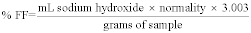 7. Method
Precision and Accuracy
7. Method
Precision and Accuracy
Test values should conform to the following statistical precision:
Variance = 0.005 Standard deviation = 0.07 95% Confidence Interval, for a single determination = 0.2 8. AuthorThis method was prepared by K.K. Tutin and M.L. Foster, Tacoma R&D Laboratory, Georgia-Pacific Resins, Inc. (Principle written by R. R. Conner.)
9. References9.1 GPAM 2221.2.
9.2 PR&C TM 2.035.
9.3 Project Report, Comparison of Free Formaldehyde Procedures, January 1990, K. Tutin.
Table 1 to Subpart EEE of Part 63 - General Provisions Applicable to Subpart EEE
40:13.0.1.1.1.1.20.23.1 :
Table 1 to Subpart EEE of Part 63 - General Provisions Applicable to Subpart EEE| Reference | Applies to subpart EEE | Explanation |
|---|---|---|
| 63.1 | Yes. | |
| 63.2 | Yes. | |
| 63.3 | Yes. | |
| 63.4 | Yes. | |
| 63.5 | Yes. | |
| 63.6(a), (b), (c), (d), and (e) | Yes. | |
| 63.6(f) | Yes | Except that the performance test requirements of Sec. 63.1207 apply instead of § 63.6(f)(2)(iii)(B). |
| 63.6(g) and (h) | Yes. | |
| 63.6(i) | Yes | Section 63.1213 specifies that the compliance date may also be extended for inability to install necessary emission control equipment by the compliance date because of implementation of pollution prevention or waste minimization controls. |
| 63.6(j) | Yes. | |
| 63.7(a) | Yes | Except § 63.1207(e)(3) allows you to petition the Administrator under § 63.7(h) to provide an extension of time to conduct a performance test. |
| 63.7(b) | Yes | Except § 63.1207(e) requires you to submit the site-specific test plan for approval at least one year before the comprehensive performance test is scheduled to begin. |
| 63.7(c) | Yes | Except § 63.1207(e) requires you to submit the site-specific test plan (including the quality assurance provisions under § 63.7(c)) for approval at least one year before the comprehensive performance test is scheduled to begin. |
| 63.7(d) | Yes. | |
| 63.7(e) | Yes | Except § 63.1207 prescribes operations during performance testing and § 63.1209 specifies operating limits that will be established during performance testing (such that testing is likely to be representative of the extreme range of normal performance). |
| 63.7(f) | Yes. | |
| 63.7(g) | Yes | Except § 63.1207(j) requiring that you submit the results of the performance test (and the notification of compliance) within 90 days of completing the test, unless the Administrator grants a time extension, applies instead of § 63.7(g)(1). |
| 63.7(h) | Yes | Except § 63.1207(c)(2) allows data in lieu of the initial comprehensive performance test, and § 63.1207(m) provides a waiver of certain performance tests. You must submit requests for these waivers with the site-specific test plan. |
| 63.8(a) and (b) | Yes. | |
| 63.8(c) | Yes | Except: (1) § 63.1211(c) that requires you to install, calibrate, and operate CMS by the compliance date applies instead of § 63.8(c)(3); and (2) the performance specifications for CO, HC, and O2 CEMS in subpart B, of this chapter requiring that the detectors measure the sample concentration at least once every 15 seconds for calculating an average emission level once every 60 seconds apply instead of § 63.8(c)(4)(ii). |
| 63.8(d) | Yes. | |
| 63.8(e) | Yes | Except § 63.1207(e) requiring you to submit the site-specific comprehensive performance test plan and the CMS performance evaluation test plan for approval at least one year prior to the planned test date applies instead of §§ 63.8(e)(2) and (3)(iii). |
| 63.8(f) and (g) | Yes. | |
| 63.9(a) | Yes. | |
| 63.9(b) | Yes | Note: Section 63.9(b)(1)(ii) pertains to notification requirements for area sources that become a major source, and § 63.9(b)(2)(v) requires a major source determination. Although area sources are subject to all provisions of this subpart (Subpart EEE), these sections nonetheless apply because the major source determination may affect the applicability of part 63 standards or title V permit requirements to other sources (i.e., other than a hazardous waste combustor) of hazardous air pollutants at the facility. |
| 63.9(c) and (d) | Yes. | |
| 63.9(e) | Yes | Except § 63.1207(e) which requires you to submit the comprehensive performance test plan for approval one year prior to the planned performance test date applies instead of § 63.9(e). |
| 63.9(f) | Yes | Section 63.9(f) applies if you are allowed under § 63.1209(a)(1)(v) to use visible determination of opacity for compliance in lieu of a COMS. |
| 63.9(g) | Yes | Except § 63.9(g)(2) pertaining to COMS does not apply. |
| 63.9(h) | Yes | Except § 63.1207(j) requiring you to submit the notification of compliance within 90 days of completing a performance test unless the Administrator grants a time extension applies instead of § 63.9(h)(2)(iii). Note: Even though area sources are subject to this subpart, the major source determination required by § 63.9(h)(2)(i)(E) is applicable to hazardous waste combustors for the reasons discussed above. |
| 63.9(i) and (j) | Yes. | |
| 63.9(k) | Yes | Only as specified in § 63.9(j). |
| 63.10 | Yes | Except reports of performance test results required under § 63.10(d)(2) may be submitted up to 90 days after completion of the test. |
| 63.11 | No. | |
| 63.12-63.15 | Yes. |
Appendix to Subpart EEE of Part 63 - Quality Assurance Procedures for Continuous Emissions Monitors Used for Hazardous Waste Combustors
40:13.0.1.1.1.1.20.23.2 :
Appendix to Subpart EEE of Part 63 - Quality Assurance Procedures for Continuous Emissions Monitors Used for Hazardous Waste Combustors 1. Applicability and Principle1.1 Applicability. These quality assurance requirements are used to evaluate the effectiveness of quality control (QC) and quality assurance (QA) procedures and the quality of data produced by continuous emission monitoring systems (CEMS) that are used for determining compliance with the emission standards on a continuous basis as specified in the applicable regulation. The QA procedures specified by these requirements represent the minimum requirements necessary for the control and assessment of the quality of CEMS data used to demonstrate compliance with the emission standards provided under this subpart EEE of part 63. Owners and operators must meet these minimum requirements and are encouraged to develop and implement a more extensive QA program. These requirements supersede those found in part 60, Appendix F, of this chapter. Appendix F does not apply to hazardous waste-burning devices.
1.2 Principle. The QA procedures consist of two distinct and equally important functions. One function is the assessment of the quality of the CEMS data by estimating accuracy. The other function is the control and improvement of the quality of the CEMS data by implementing QC policies and corrective actions. These two functions form a control loop. When the assessment function indicates that the data quality is inadequate, the source must immediately stop burning hazardous waste. The CEM data control effort must be increased until the data quality is acceptable before hazardous waste burning can resume.
a. In order to provide uniformity in the assessment and reporting of data quality, this procedure explicitly specifies the assessment methods for response drift and accuracy. The methods are based on procedures included in the applicable performance specifications provided in appendix B to part 60 of this chapter. These procedures also require the analysis of the EPA audit samples concurrent with certain reference method (RM) analyses as specified in the applicable RM's.
b. Because the control and corrective action function encompasses a variety of policies, specifications, standards, and corrective measures, this procedure treats QC requirements in general terms to allow each source owner or operator to develop a QC system that is most effective and efficient for the circumstances.
2. Definitions2.1 Continuous Emission Monitoring System (CEMS). The total equipment required for the determination of a pollutant concentration. The system consists of the following major subsystems:
2.1.1 Sample Interface. That portion of the CEMS used for one or more of the following: sample acquisition, sample transport, and sample conditioning, or protection of the monitor from the effects of the stack effluent.
2.1.2 Pollutant Analyzer. That portion of the CEMS that senses the pollutant concentration and generates a proportional output.
2.1.3 Diluent Analyzer. That portion of the CEMS that senses the diluent gas (O2) and generates an output proportional to the gas concentration.
2.1.4 Data Recorder. That portion of the CEMS that provides a permanent record of the analyzer output. The data recorder may provide automatic data reduction and CEMS control capabilities.
2.2 Relative Accuracy (RA). The absolute mean difference between the pollutant concentration determined by the CEMS and the value determined by the reference method (RM) plus the 2.5 percent error confidence coefficient of a series of test divided by the mean of the RM tests or the applicable emission limit.
2.3 Calibration Drift (CD). The difference in the CEMS output readings from the established reference value after a stated period of operation during which no unscheduled maintenance, repair, or adjustment took place.
2.4 Zero Drift (ZD). The difference in CEMS output readings at the zero pollutant level after a stated period of operation during which no unscheduled maintenance, repair, or adjustment took place.
2.5 Calibration Standard. Calibration standards produce a known and unchanging response when presented to the pollutant analyzer portion of the CEMS, and are used to calibrate the drift or response of the analyzer.
2.6 Relative Accuracy Test Audit (RATA). Comparison of CEMS measurements to reference method measurements in order to evaluate relative accuracy following procedures and specification given in the appropriate performance specification.
2.7 Absolute Calibration Audit (ACA). Equivalent to calibration error (CE) test defined in the appropriate performance specification using NIST traceable calibration standards to challenge the CEMS and assess accuracy.
2.8 Rolling Average. The average emissions, based on some (specified) time period, calculated every minute from a one-minute average of four measurements taken at 15-second intervals.
3. QA/QC Requirements3.1 QC Requirements. a. Each owner or operator must develop and implement a QC program. At a minimum, each QC program must include written procedures describing in detail complete, step-by-step procedures and operations for the following activities.
1. Checks for component failures, leaks, and other abnormal conditions.
2. Calibration of CEMS.
3. CD determination and adjustment of CEMS.
4. Integration of CEMS with the automatic waste feed cutoff (AWFCO) system.
5. Preventive Maintenance of CEMS (including spare parts inventory).
6. Data recording, calculations, and reporting.
7. Checks of record keeping.
8. Accuracy audit procedures, including sampling and analysis methods.
9. Program of corrective action for malfunctioning CEMS.
10. Operator training and certification.
11. Maintaining and ensuring current certification or naming of cylinder gasses, metal solutions, and particulate samples used for audit and accuracy tests, daily checks, and calibrations.
b. Whenever excessive inaccuracies occur for two consecutive quarters, the current written procedures must be revised or the CEMS modified or replaced to correct the deficiency causing the excessive inaccuracies. These written procedures must be kept on record and available for inspection by the enforcement agency.
3.2 QA Requirements. Each source owner or operator must develop and implement a QA plan that includes, at a minimum, the following.
1. QA responsibilities (including maintaining records, preparing reports, reviewing reports).
2. Schedules for the daily checks, periodic audits, and preventive maintenance.
3. Check lists and data sheets.
4. Preventive maintenance procedures.
5. Description of the media, format, and location of all records and reports.
6. Provisions for a review of the CEMS data at least once a year. Based on the results of the review, the owner or operator must revise or update the QA plan, if necessary.
4. CD and ZD Assessment and Daily System Audit4.1 CD and ZD Requirement. Owners and operators must check, record, and quantify the ZD and the CD at least once daily (approximately 24 hours) in accordance with the method prescribed by the manufacturer. The CEMS calibration must, at a minimum, be adjusted whenever the daily ZD or CD exceeds the limits in the Performance Specifications. If, on any given ZD and/or CD check the ZD and/or CD exceed(s) two times the limits in the Performance Specifications, or if the cumulative adjustment to the ZD and/or CD (see Section 4.2) exceed(s) three times the limits in the Performance Specifications, hazardous waste burning must immediately cease and the CEMS must be serviced and recalibrated. Hazardous waste burning cannot resume until the owner or operator documents that the CEMS is in compliance with the Performance Specifications by carrying out an ACA.
4.2 Recording Requirements for Automatic ZD and CD Adjusting Monitors. Monitors that automatically adjust the data to the corrected calibration values must record the unadjusted concentration measurement prior to resetting the calibration, if performed, or record the amount of the adjustment.
4.3 Daily System Audit. The audit must include a review of the calibration check data, an inspection of the recording system, an inspection of the control panel warning lights, and an inspection of the sample transport and interface system (e.g., flowmeters, filters, etc.) as appropriate.
4.4 Data Recording and Reporting. All measurements from the CEMS must be retained in the operating record for at least 5 years.
5. Performance Evaluation for CO, O2, and HC CEMSCarbon Monoxide (CO), Oxygen (O2), and Hydrocarbon (HC) CEMS. An Absolute Calibration Audit (ACA) must be conducted quarterly, and a Relative Accuracy Test Audit (RATA) (if applicable, see sections 5.1 and 5.2) must be conducted yearly. An Interference Response Tests must be performed whenever an ACA or a RATA is conducted. When a performance test is also required under § 63.1207 to document compliance with emission standards, the RATA must coincide with the performance test. The audits must be conducted as follows.
5.1 Relative Accuracy Test Audit (RATA). This requirement applies to O2 and CO CEMS. The RATA must be conducted at least yearly. Conduct the RATA as described in the RA test procedure (or alternate procedures section) described in the applicable Performance Specifications. In addition, analyze the appropriate performance audit samples received from the EPA as described in the applicable sampling methods.
5.2 Absolute Calibration Audit (ACA). The ACA must be conducted at least quarterly except in a quarter when a RATA (if applicable, see section 5.1) is conducted instead. Conduct an ACA as described in the calibration error (CE) test procedure described in the applicable Performance Specifications.
5.3 Interference Response Test. The interference response test must be conducted whenever an ACA or RATA is conducted. Conduct an interference response test as described in the applicable Performance Specifications.
5.4 Excessive Audit Inaccuracy. If the RA from the RATA or the CE from the ACA exceeds the criteria in the applicable Performance Specifications, hazardous waste burning must cease immediately. Hazardous waste burning cannot resume until the owner or operator takes corrective measures and audit the CEMS with a RATA to document that the CEMS is operating within the specifications.
6. Other Requirements6.1 Performance Specifications. CEMS used by owners and operators of HWCs must comply with the following performance specifications in appendix B to part 60 of this chapter:
Table I: Performance Specifications for CEMS
| CEMS | Performance specification |
|---|---|
| Carbon monoxide | 4B |
| Oxygen | 4B |
| Total hydrocarbons | 8A |
6.2 Downtime due to Calibration. Facilities may continue to burn hazardous waste for a maximum of 20 minutes while calibrating the CEMS. If all CEMS are calibrated at once, the facility must have twenty minutes to calibrate all the CEMS. If CEMS are calibrated individually, the facility must have twenty minutes to calibrate each CEMS. If the CEMS are calibrated individually, other CEMS must be operational while the individual CEMS is being calibrated.
6.3 Span of the CEMS.
6.3.1 CO CEMS. The CO CEM must have two ranges, a low range with a span of 200 ppmv and a high range with a span of 3000 ppmv at an oxygen correction factor of 1. A one-range CEM may be used, but it must meet the performance specifications for the low range in the specified span of the low range.
6.3.2 O2 CEMS. The O2 CEM must have a span of 25 percent. The span may be higher than 25 percent if the O2 concentration at the sampling point is greater than 25 percent.
6.3.3 HC CEMS. The HC CEM must have a span of 100 ppmv, expressed as propane, at an oxygen correction factor of 1.
6.3.4 CEMS Span Values. When the Oxygen Correction Factor is Greater than 2. When an owner or operator installs a CEMS at a location of high ambient air dilution, i.e., where the maximum oxygen correction factor as determined by the permitting agency is greater than 2, the owner or operator must install a CEM with a lower span(s), proportionate to the larger oxygen correction factor, than those specified above.
6.3.5 Use of Alternative Spans. Owner or operators may request approval to use alternative spans and ranges to those specified. Alternate spans must be approved in writing in advance by the Administrator. In considering approval of alternative spans and ranges, the Administrator will consider that measurements beyond the span will be recorded as values at the maximum span for purposes of calculating rolling averages.
6.3.6 Documentation of Span Values. The span value must be documented by the CEMS manufacturer with laboratory data.
6.4.1 Moisture Correction. Method 4 of appendix A, part 60 of this chapter, must be used to determine moisture content of the stack gasses.
6.4.2 Oxygen Correction Factor. Measured pollutant levels must be corrected for the amount of oxygen in the stack according to the following formula:
 Where: Pc
= concentration of the pollutant or standard corrected to 7 percent
oxygen, dry basis; Pm = measured concentration of the pollutant,
dry basis; E = volume fraction of oxygen in the combustion air fed
into the device, on a dry basis (normally 21 percent or 0.21 if
only air is fed); Y = measured fraction of oxygen on a dry basis at
the sampling point.
Where: Pc
= concentration of the pollutant or standard corrected to 7 percent
oxygen, dry basis; Pm = measured concentration of the pollutant,
dry basis; E = volume fraction of oxygen in the combustion air fed
into the device, on a dry basis (normally 21 percent or 0.21 if
only air is fed); Y = measured fraction of oxygen on a dry basis at
the sampling point.
The oxygen correction factor is:

6.4.3 Temperature Correction. Correction values for temperature are obtainable from standard reference materials.
6.5 Rolling Average. A rolling average is the arithmetic average of all one-minute averages over the averaging period.
6.5.1 One-Minute Average for CO and HHC CEMS. One-minute averages are the arithmetic average of the four most recent 15-second observations and must be calculated using the following equation:
Where: c = the one minute average ci = a fifteen-second observation from the CEMFifteen second observations must not be rounded or smoothed. Fifteen-second observations may be disregarded only as a result of a failure in the CEMS and allowed in the source's quality assurance plan at the time of the CEMS failure. One-minute averages must not be rounded, smoothed, or disregarded.
6.5.2 Ten Minute Rolling Average Equation. The ten minute rolling average must be calculated using the following equation:
 Where:
CRA = The concentration of the standard, expressed as a
rolling average c i = a one minute average
Where:
CRA = The concentration of the standard, expressed as a
rolling average c i = a one minute average
6.5.3 Hourly Rolling Average Equation for CO and THC CEMS and Operating Parameter Limits. The rolling average, based on a specific number integer of hours, must be calculated using the following equation:
 Where:
cRA = The concentration of the standard, expressed as a
rolling average c i = a one minute average
Where:
cRA = The concentration of the standard, expressed as a
rolling average c i = a one minute average
6.5.4 Averaging Periods for CEMS other than CO and THC. The averaging period for CEMS other than CO and THC CEMS must be calculated as a rolling average of all one-hour values over the averaging period. An hourly average is comprised of 4 measurements taken at equally spaced time intervals, or at most every 15 minutes. Fewer than 4 measurements might be available within an hour for reasons such as facility downtime or CEMS calibration. If at least two measurements (30 minutes of data) are available, an hourly average must be calculated. The n-hour rolling average is calculated by averaging the n most recent hourly averages.
6.6 Units of the Standards for the Purposes of Recording and Reporting Emissions. Emissions must be recorded and reported expressed after correcting for oxygen, temperature, and moisture. Emissions must be reported in metric, but may also be reported in the English system of units, at 7 percent oxygen, 20 °C, and on a dry basis.
6.7 Rounding and Significant Figures. Emissions must be rounded to two significant figures using ASTM procedure E-29-90 or its successor. Rounding must be avoided prior to rounding for the reported value.
7. Bibliography1. 40 CFR part 60, appendix F, “Quality Assurance Procedures: Procedure 1. Quality Assurance Requirements for Gas continuous Emission Monitoring Systems Used For Compliance Determination”.
[64 FR 53038, Sept. 30, 1999, as amended at 65 FR 42301, July 10, 2000]Table 1 to Subpart GGG of Part 63 - General Provisions Applicability to Subpart GGG
40:13.0.1.1.1.3.20.13.3 :
Table 1 to Subpart GGG of Part 63 - General Provisions Applicability to Subpart GGG| General provisions reference | Summary of requirements | Applies to subpart GGG | Comments |
|---|---|---|---|
| 63.1(a)(1) | General applicability of the General Provisions | Yes | Additional terms defined in § 63.1251; when overlap between subparts A and GGG of this part, subpart GGG takes precedence. |
| 63.1(a)(2-7) | Yes | ||
| 63.1(a)(8) | No | Discusses state programs. | |
| 63.1(a)(9-14) | Yes | ||
| 63.1(b)(1) | Initial applicability determination | Yes | Subpart GGG clarifies the applicability in § 63.1250. |
| 63.1(b)(2) | Title V operating permit - see part 70 | Yes | All major affected sources are required to obtain a title V permit. |
| 63.1(b)(3) | Record of the applicability determination | Yes | All affected sources are subject to subpart GGG according to the applicability definition of subpart GGG. |
| 63.1(c)(1) | Applicability after standards are set | Yes | Subpart GGG clarifies the applicability of each paragraph of subpart A to sources subject to subpart GGG. |
| 63.1(c)(2) | Title V permit requirement | No | All major affected sources are required to obtain a title V permit. Area sources are not subject to subpart GGG. |
| 63.1(c)(3) | Reserved | ||
| 63.1(c)(4) | Requirements for existing source that obtains an extension of compliance | Yes | |
| § 63.1(c)(5) | Notification requirements for an area source that increases HAP emissions to major source levels | Yes | |
| 63.1(c)(6) | Reclassification | Yes | |
| 63.1(d) | [Reserved] | NA | |
| 63.1(e) | Applicability of permit program before a relevant standard has been set | Yes | |
| 63.2 | Definitions. | Yes | Additional terms defined in § 63.1251; when overlap between subparts A and GGG of this part occurs, subpart GGG takes precedence. |
| 63.3 | Units and abbreviations. | Yes | Other units used in subpart GGG are defined in that subpart. |
| 63.4 | Prohibited activities. | Yes | |
| 63.5(a) | Construction and reconstruction - applicability | Yes | Except replace the terms “source” and “stationary source” with “affected source”. |
| 63.5(b)(1) | Upon construction, relevant standards for new sources | Yes | |
| 63.5(b)(2) | [Reserved] | NA | |
| 63.5(b)(3) | New construction/reconstruction | Yes | Except for changes and additions authorized under § 52.2454 of this title. However, the requirement to submit the Precompliance report at least 90 days before the compliance date still applies. |
| 63.5(b)(4) | Construction/reconstruction notification | Yes | |
| 63.5(b)(5) | Construction/reconstruction compliance | Yes | |
| 63.5(b)(6) | Equipment addition or process change | Yes | |
| 63.5(c) | [Reserved] | NA | |
| 63.5(d) | Application for approval of construction/reconstruction | Yes | Except for certain provisions identified in 63.1259(a)(5) |
| § 63.5(e) | Construction/reconstruction approval | Yes | |
| 63.5(f) | Construction/reconstruction approval based on prior State review. | Yes | Except replace “source” with “affected source”. |
| 63.6(a)(1) | Compliance with standards and maintenance requirements | Yes | |
| 63.6(a)(2) | Requirements for area source that increases emissions to become major | Yes | |
| 63.6(b)(1-2) | Compliance dates for new and reconstructed sources | No | Subpart GGG specifies compliance dates. |
| 63.6(b)(3-6) | Compliance dates for area sources that become major sources | Yes | |
| 63.6 (b)(7) | Compliance dates for new sources resulting from new unaffected area sources becoming subject to standards | No | Subpart GGG specifies NS applicability and compliance dates |
| 63.6(c) | Compliance dates for existing sources | Yes | Except replace “source” with “affected source”. Subpart GGG specifies compliance dates. |
| § 63.6(e)(1)(i) | Requirements during periods of startup, shutdown, and malfunction | No | See 63.1250(g)(3) for general duty requirement. Any cross-reference to 63.6(e)(1)(i) in any other general provision incorporated by reference shall be treated as a cross-reference to 63.1250(g)(3). |
| § 63.6(e)(1)(ii) | Malfunction correction requirements | No. | |
| § 63.6(e)(1)(iii) | Enforceability of operation and maintenance requirements | Yes. | |
| § 63.6(e)(2) | Reserved | No | Section reserved. |
| § 63.6(e)(3) | Startup, shutdown, and malfunction plan requirements | No. | |
| 63.6(f)(1) | Applicability of nonopacity emission standards | No. | |
| 63.6(f)(2)-(3) | Methods of determining compliance and findings compliance | Yes. | |
| 63.6(g) | Use of an alternative nonopacity emission standard | Yes. | |
| 63.6(h) | Opacity and visible emission standards | No | Subpart GGG does not contain any opacity or visible emission standards. |
| § 63.6(i)(1) through (7) | Requests for compliance extensions | No | § 63.1250(f)(6) specifies provisions for compliance extensions. |
| § 63.6(i)(8) through (14) | Approval of compliance extensions | Yes | Except references to § 63.6(i)(4) through (6) mean § 63.1250(f)(6). |
| 63.6(j) | Exemption from compliance with emission standards | Yes | |
| 63.7(a)(1) | Performance testing requirements | Yes | Subpart GGG also specifies required testing and compliance procedures. |
| 63.7(a)(2)(i)-(ix) | Yes | Except substitute “150 days” instead of “180 days.” | |
| 63.7(a)(3) | Yes | ||
| 63.7(b)(1) | Notification of performance test | Yes | |
| 63.7(b)(2) | Notification of delay in conducting a scheduled performance test | Yes | |
| 63.7(c) | Quality assurance program | Yes | Except that the test plan must be submitted with the notification of the performance test. |
| 63.7(d) | Performance testing facilities. | Yes | Except replace “source” with “affected source”. |
| 63.7(e)(1) | Conduct of performance tests | No | See 63.1257(a) text. Any cross-reference to 63.7(e)(1) in any other general provision incorporated by reference shall be treated as a cross-reference to 63.1257(a). |
| 63.7(e)(2)-(4) | Performance tests requirements | Yes. | |
| 63.7(f) | Use of alternative test method | Yes | |
| 63.7(g) | Data analysis, recordkeeping, and reporting | Yes | |
| 63.7(h) | Waiver of performance tests | Yes | |
| 63.8(a) | Monitoring requirements | Yes | See § 63.1258. |
| 63.8(b)(1) | Conduct of monitoring | Yes | |
| 63.8(b)(2) | CMS and combined effluents | No | § 63.1258 of subpart GGG provides specific CMS requirements. |
| 63.8(b)(3)-(c)(4) | CMS requirements | Yes | § 63.1259 also specifies recordkeeping for CMS. |
| 63.8(c)(5) | COMS operation requirements | No | |
| 63.8(c)(6)-(8) | CMS calibration and malfunction provisions | No | Calibration procedures are provided in § 63.1258. |
| 63.8(d)(1)-(2) | CMS quality control program requirements | Yes. | |
| 63.8(d)(3) | CMS quality control program recordkeeping requirements | Yes, except for last sentence | |
| 63.8(e)(1) | Performance evaluations of CMS | Yes | |
| 63.8(e)(2) | Notification of performance evaluation | Yes | |
| 63.8(e)(3-4) | CMS requirements/alternatives | Yes | |
| § 63.8(e)(5)(i) | Reporting performance evaluation results | Yes | See § 63.1260(a). |
| 63.1260 (a). | |||
| 63.8(e)(5)(ii) | Results of COMS performance evaluation | No | Subpart GGG does not contain any opacity or visible emission standards. |
| 63.8(f)-(g) | Alternative monitoring method/reduction of monitoring data | Yes | |
| 63.9(a)-(d) | Notification requirements - Applicability and general information | Yes | § 63.1260 (b) also specifies initial notification requirement. |
| 63.9(e) | Notification of performance test | Yes | § 63.1260 (l) also specifies notification requirement for performance test. |
| 63.9(f) | Notification of opacity and visible emissions observations | No | Subpart GGG does not contain any opacity or visible emission standards. |
| 63.9(g)(1) | Additional notification requirements for sources with CMS | Yes | § 63.1260 (d) also specifies notification requirement for performance evaluation. |
| 63.9(g)(2) | Notification of compliance with opacity emission standard | No | Subpart GGG does not contain any opacity or visible emission standards. |
| 63.9(g)(3) | Notification that criterion to continue use of alternative to relative accuracy testing has been exceeded | Yes | § 63.1260 (d) also specifies notification requirement for performance evaluation. |
| 63.9(h) | Notification of compliance status | Yes | Specified in § 63.1260(f). Due 150 days after compliance date. |
| 63.9(i) | Adjustment to time periods or postmark deadlines for submittal and review of required communications | Yes | |
| 63.9(j) | Change in information provided | Yes | For change in major source status only. |
| 63.9(k) | Electronic reporting procedures | Yes | Only as specified in § 63.9(j). |
| 63.10(a) | Recordkeeping requirements | Yes | |
| 63.1259. | |||
| 63.10(b)(1) | Records retention | Yes | Also stated in § 63.1259. |
| 63.10(b)(2) | Information and documentation to support notifications | No | Subpart GGG specifies recordkeeping requirements. |
| 63.10(b)(3) | Records retention for sources not subject to relevant standard | Yes | Also stated in § 63.1259 (a)(2). |
| 63.10(c)(1)-(9) | Additional recordkeeping requirements for sources with continuous monitoring systems | Yes. | |
| 63.10(c)(10) | Malfunction recordkeeping requirement | No | Subpart GGG specifies recordkeeping requirements. |
| 63.10(c)(11) | Malfunction corrective action recordkeeping requirement | No | Subpart GGG specifies recordkeeping requirements. |
| 63.10(c)(12)-(14) | Additional recordkeeping requirements for sources with continuous monitoring systems | Yes. | |
| 63.10(c)(15) | Additional SSM recordkeeping requirements | No. | |
| 63.10(d)(1)-(2) | General reporting requirements | Yes. | |
| 63.10(d)(3) | Reporting results of opacity or visible emissions observations | No | Subpart GGG does not include any opacity or visible emission standards. |
| 63.10(d)(4) | Progress report requirements | Yes. | |
| 63.10(d)(5) | Startup, shutdown, and malfunction report requirements | No | Subpart GGG specifies reporting requirements. |
| 63.10(e) | Additional CMS reporting requirements | Yes | |
| 63.10(f) | Waiver of recordkeeping or reporting requirements. | Yes | |
| 63.11 | Control device and equipment leak work practice requirements | Yes | |
| 63.13 | Addresses of State air pollution control agencies | Yes | |
| 63.14 | Incorporations by reference | Yes | |
| 63.15 | Availability of information and confidentiality | Yes |
Table 2 to Subpart GGG of Part 63 - Partially Soluble HAP
40:13.0.1.1.1.3.20.13.4 :
Table 2 to Subpart GGG of Part 63 - Partially Soluble HAP| 1,1,1-Trichloroethane (methyl chloroform) | Chloroform |
| 1,1,2,2-Tetrachloroethane | Chloromethane |
| 1,1,2-Trichloroethane | Chloroprene |
| 1,1-Dichloroethylene (vinylidene chloride) | Cumene |
| 1,2-Dibromoethane | Dichloroethyl ether |
| 1,2-Dichloroethane (ethylene dichloride) | Dinitrophenol |
| 1,2-Dichloropropane | Epichlorohydrin |
| 1,3-Dichloropropene | Ethyl acrylate |
| 2,4,5-Trichlorophenol | Ethylbenzene |
| 2-Butanone (mek) | Ethylene oxide |
| 1,4-Dichlorobenzene | Hexachlorobenzene |
| 2-Nitropropane | Hexachlorobutadiene |
| 4-Methyl-2-pentanone (MIBK) | Hexachloroethane |
| Acetaldehyde | Methyl methacrylate |
| Acrolein | Methyl-t-butyl ether |
| Acrylonitrile | Methylene chloride |
| Allyl chloride | N,N-dimethylaniline |
| Benzene | Propionaldehyde |
| Benzyl chloride | Propylene oxide |
| Biphenyl | Styrene |
| Bromoform (tribromomethane) | Tetrachloroethene (perchloroethylene) |
| Bromomethane | Tetrachloromethane (carbon tetrachloride |
| Butadiene | Toluene |
| Carbon disulfide | Trichlorobenzene (1,2,4-) |
| Chlorobenzene | Trichloroethylene |
| Chloroethane (ethyl chloride) | Trimethylpentane |
| Vinyl acetate | Xylene (p) |
| Vinyl chloride | N-hexane |
| Xylene (m) | |
| Xylene (o) |
Table 3 to Subpart GGG of Part 63 - Soluble HAP
40:13.0.1.1.1.3.20.13.5 :
Table 3 to Subpart GGG of Part 63 - Soluble HAP| Compound |
|---|
| 1,1-Dimethylhydrazine. |
| 1,4-Dioxane. |
| Acetonitrile. |
| Acetophenone. |
| Diethyl sulfate. |
| Dimethyl sulfate. |
| Dinitrotoluene. |
| Ethylene glycol dimethyl ether. |
| Ethylene glycol monobutyl ether acetate. |
| Ethylene glycol monomethyl ether acetate. |
| Isophorone. |
| Methanol (methyl alcohol). |
| Nitrobenzene. |
| Toluidene. |
| Triethylamine. |
Table 4 to Subpart GGG of Part 63 - Monitoring Requirements for Control Devices a
40:13.0.1.1.1.3.20.13.6 :
Table 4 to Subpart GGG of Part 63 - Monitoring Requirements for Control Devices a| Control device | Monitoring equipment required | Parameters to be monitored | Frequency |
|---|---|---|---|
| All control devices | 1. Flow indicator installed at all bypass lines to the atmosphere and equipped with continuous recorder or | 1. Presence of flow diverted from the control device to the atmosphere or | Hourly records of whether the flow indicator was operating and whether a diversion was detected at any time during each hour. |
| 2. Valves sealed closed with car-seal or lock-and-key configuration | 2. Monthly inspections of sealed valves | Monthly. | |
| Scrubber | Liquid flow rate or pressure drop mounting device. Also a pH monitor if the scrubber is used to control acid emissions | 1. Liquid flow rate into or out of the scrubber or the pressure drop across the scrubber | 1. Every 15 minutes. |
| 2. pH of effluent scrubber liquid | 2. Once a day. | ||
| Thermal incinerator | Temperature monitoring device installed in firebox or in ductwork immediately downstream of firebox b | Firebox temperature | Every 15 minutes. |
| Catalytic incinerator | Temperature monitoring device installed in gas stream immediately before and after catalyst bed | Temperature difference across catalyst bed | Every 15 minutes. |
| Flare | Heat sensing device installed at the pilot light | Presence of a flame at the pilot light | Every 15 minutes. |
| Boiler or process heater <44 mega watts and vent stream is not mixed with the primary fuel | Temperature monitoring device installed in firebox b | Combustion temperature | Every 15 minutes. |
| Condenser | Temperature monitoring device installed at condenser exit | Condenser exit (product side) temperature | Every 15 minutes. |
| Carbon adsorber (nonregenerative) | None | Operating time since last replacement | N/A. |
| Carbon adsorber (regenerative) | Stream flow monitoring device, and | 1. Total regeneration stream mass or volumetric flow during carbon bed regeneration cycle(s) | 1. For each regeneration cycle, record the total regeneration stream mass or volumetric flow. |
| Carbon bed temperature monitoring device | 2. Temperature of carbon bed after regeneration | 2. For each regeneration cycle, record the maximum carbon bed-temperature. | |
| 3. Temperature of carbon bed within 15 minutes of completing any cooling cycle(s) | 3. Within 15 minutes of completing any cooling cycle, record the carbon bed temperature. | ||
| 4. Operating time since end of last regeneration | 4. Operating time to be based on worst-case conditions. | ||
| 5. Check for bed poisoning | 5. Yearly. |
a As an alternative to the monitoring requirements specified in this table, the owner or operator may use a CEM meeting the requirements of Performance Specifications 8 or 9 of appendix B of part 60 to monitor TOC every 15 minutes.
b Monitor may be installed in the firebox or in the ductwork immediately downstream of the firebox before any substantial heat exchange is encountered.
Table 5 to Subpart GGG of Part 63 - Control Requirements for Items of Equipment That Meet the Criteria of § 63.1252(f)
40:13.0.1.1.1.3.20.13.7 :
Table 5 to Subpart GGG of Part 63 - Control Requirements for Items of Equipment That Meet the Criteria of § 63.1252(f)| Item of equipment | Control requirement a |
|---|---|
| Drain or drain hub | (a) Tightly fitting solid cover (TFSC); or |
| (b) TFSC with a vent to either a process or to a control device meeting the requirements of § 63.1256(h)(2); or | |
| (c) Water seal with submerged discharge or barrier to protect discharge from wind. | |
| Manhole b | (a) TFSC; or |
| (b) TSFC with a vent to either a process or to a control device meeting the requirements of § 63.1256(h)(2); or | |
| (c) If the item is vented to the atmosphere, use a TFSC with a properly operating water seal at the entrance or exit to the item to restrict ventilation in the collection system. The vent pipe shall be at least 90 cm in length and not exceeding 10.2 cm in nominal inside diameter. | |
| Lift station | (a) TFSC; or |
| (b) TFSC with a vent to either a process or to a control device meeting the requirements of § 63.1256(h)(2); or | |
| (c) If the lift station is vented to the atmosphere, use a TFSC with a properly operating water seal at the entrance or exit to the item to restrict ventilation in the collection system. The vent pipe shall be at least 90 cm in length and not exceeding 10.2 cm in nominal inside diameter. The lift station shall be level controlled to minimize changes in the liquid level. | |
| Trench | (a) TFSC; or |
| (b) TFSC with a vent to either a process or to a control device meeting the requirements of § 63.1256(h)(2); or | |
| (c) If the item is vented to the atmosphere, use a TFSC with a properly operating water seal at the entrance or exit to the item to restrict ventilation in the collection system. The vent pipe shall be at least 90 cm in length and not exceeding 10.2 cm in nominal inside diameter. | |
| Pipe | Each pipe shall have no visible gaps in joints, seals, or other emission interfaces. |
| Oil/Water separator | (a) Equip with a fixed roof and route vapors to a process or equip with a closed-vent system that routes vapors to a control device meeting the requirements of § 63.1256(h)(2); or |
| (b) Equip with a floating roof that meets the equipment specifications of § 60.693(a)(1)(i), (a)(1)(ii), (a)(2), (a)(3), and (a)(4). | |
| Tank | Maintain a fixed roof and consider vents as process vents. c |
a Where a tightly fitting solid cover is required, it shall be maintained with no visible gaps or openings, except during periods of sampling, inspection, or maintenance.
b Manhole includes sumps and other points of access to a conveyance system.
c A fixed roof may have openings necessary for proper venting of the tank, such as pressure/vacuum vent, j-pipe vent.
Table 6 to Subpart GGG of Part 63 - Wastewater - Compliance Options for Wastewater Tanks
40:13.0.1.1.1.3.20.13.8 :
Table 6 to Subpart GGG of Part 63 - Wastewater - Compliance Options for Wastewater Tanks| Capacity, m 3 | Maximum true vapor pressure, kPa | Control requirements |
|---|---|---|
| <75 | § 63.1256(b)(1). | |
| >75 and <151 | <13.1 | § 63.1256(b)(1). |
| >13.1 | § 63.1256(b)(2). | |
| >151 | <5.2 | § 63.1256(b)(1). |
| >5.2 | § 63.1256(b)(2). |
Table 7 to Subpart GGG of Part 63 - Wastewater - Inspection and Monitoring Requirements for Waste Management Units
40:13.0.1.1.1.3.20.13.9 :
Table 7 to Subpart GGG of Part 63 - Wastewater - Inspection and Monitoring Requirements for Waste Management Units| To comply with | Inspection or monitoring requirement | Frequency of inspection or monitoring | Method |
|---|---|---|---|
| TANKS: | |||
| 63.1256(b)(3)(i) | Inspect fixed roof and all openings for leaks | Initially Semiannually | Visual. |
| 63.1256(b)(4) | Inspect floating roof in accordance with §§ 63.120(a)(2) and (a)(3) | See §§ 63.120(a)(2) and (a)(3) | Visual. |
| 63.1256(b)(5) | Measure floating roof seal gaps in accordance with §§ 63.120(b)(2)(i) through (b)(4) | See § 63.120(b)(2)(i) through (b)(4). | |
| - Primary seal gaps | Initially Once every 5 years (annually if no secondary seal). | ||
| - Secondary seal gaps | Initially Semiannually | ||
| 63.1256(b)(7) 63.1256(b)(8) |
Inspect wastewater tank for control equipment failures and improper work practices | Initially Semiannually | Visual. |
| SURFACE IMPOUNDMENTS: | |||
| 63.1256(c)(1)(i) | Inspect cover and all openings for leaks | Initially Semiannually | Visual. |
| 63.1256(c)(2) | Inspect surface impoundment for control equipment failures and improper work practices | Initially Semiannually | Visual. |
| CONTAINERS: | |||
|
63.1256(d)(1)(i) 63.1256(d)(1)(ii) |
Inspect cover and all openings for leaks | Initially Semiannually | Visual. |
| 63.1256(d)(3)(i) | Inspect enclosure and all openings for leaks | Initially Semiannually | Visual. |
| 63.1256(d)(4) | Inspect container for control equipment failures and improper work practices | Initially Semiannually | Visual. |
| INDIVIDUAL DRAIN SYSTEMS a: | |||
| 63.1256(e)(1)(i) | Inspect cover and all openings to ensure there are no gaps, cracks, or holes | Initially Semiannually | Visual. |
| 63.1256(e)(2) | Inspect individual drain system for control equipment failures and improper work practices | Initially Semiannually | Visual. |
| 63.1256(e)(4)(i) | Verify that sufficient water is present to properly maintain integrity of water seals | Initially Semiannually | Visual. |
|
63.1256(e)(4)(ii) 63.1256(e)(5)(i) |
Inspect all drains using tightly-fitted caps or plugs to ensure caps and plugs are in place and properly installed | Initially Semiannually | Visual. |
| 63.1256(e)(5)(ii) | Inspect all junction boxes to ensure covers are in place and have no visible gaps, cracks, or holes | Initially Semiannually | Visual or smoke test or other means as specified. |
| 63.1256(e)(5)(iii) | Inspect unburied portion of all sewer lines for cracks and gaps | Initially Semiannually | Visual. |
| OIL-WATER SEPARATORS: | |||
| 63.1256(f)(2)(i) | Inspect fixed roof and all openings for leaks | Initially Semiannually | Visual. |
| 63.1256(f)(3) | Measure floating roof seal gaps in accordance with 40 CFR 60.696(d)(1) | Initially b | See 40 CFR 60.696(d)(1). |
| - Primary seal gaps | Once every 5 years. | ||
| 63.1256(f)(3) | - Secondary seal gaps | Initially b Annually. | |
| 63.1256(f)(4) | Inspect oil-water separator for control equipment failures and improper work practices | Initially Semiannually | Visual. |
a As specified in § 63.1256(e), the owner or operator shall comply with either the requirements of § 63.1256(e)(1) and (2) or § 63.1256(e)(4) and (5).
b Within 60 days of installation as specified in § 63.1256(f)(3).
Table 8 to Subpart GGG of Part 63 - Fraction Measured (Fm) for HAP Compounds in Wastewater Streams
40:13.0.1.1.1.3.20.13.10 :
Table 8 to Subpart GGG of Part 63 - Fraction Measured (Fm) for HAP Compounds in Wastewater Streams| Chemical name | CAS No. a | Fm |
|---|---|---|
| Acetaldehyde | 75070 | 1.00 |
| Acetonitrile | 75058 | 0.99 |
| Acetophenone | 98862 | 0.31 |
| Acrolein | 107028 | 1.00 |
| Acrylonitrile | 107131 | 1.00 |
| Allyl chloride | 107051 | 1.00 |
| Benzene | 71432 | 1.00 |
| Benzyl chloride | 100447 | 1.00 |
| Biphenyl | 92524 | 0.86 |
| Bromoform | 75252 | 1.00 |
| Butadiene (1,3-) | 106990 | 1.00 |
| Carbon disulfide | 75150 | 1.00 |
| Carbon tetrachloride | 56235 | 1.00 |
| Chlorobenzene | 108907 | 0.96 |
| Chloroform | 67663 | 1.00 |
| Chloroprene (2-Chloro-1,3-butadiene) | 126998 | 1.00 |
| Cumene | 98828 | 1.00 |
| Dichlorobenzene (p-1,4-) | 106467 | 1.00 |
| Dichloroethane (1,2-) (Ethylene dichloride) | 107062 | 1.00 |
| Dichloroethylether (Bis(2-Chloroethyl ether)) | 111444 | 0.76 |
| Dichloropropene (1,3-) | 542756 | 1.00 |
| Diethyl sulfate | 64675 | 0.0025 |
| Dimethyl sulfate | 77781 | 0.086 |
| Dimethylaniline (N,N-) | 121697 | 0.00080 |
| Dimethylhydrazine (1,1-) | 57147 | 0.38 |
| Dinitrophenol (2,4-) | 51285 | 0.0077 |
| Dinitrotoluene (2,4-) | 121142 | 0.085 |
| Dioxane (1,4-) (1,4-Diethyleneoxide) | 123911 | 0.87 |
| Epichlorohydrin(1-Chloro-2,3-epoxypropane) | 106898 | 0.94 |
| Ethyl acrylate | 140885 | 1.00 |
| Ethylbenzene | 100414 | 1.00 |
| Ethyl chloride (Chloroethane) | 75003 | 1.00 |
| Ethylene dibromide (Dibromomethane) | 106934 | 1.00 |
| Ethylene glycol dimethyl ether | 110714 | 0.86 |
| Ethylene glycol monobutyl ether acetate | 112072 | 0.043 |
| Ethylene glycol monomethyl ether acetate | 110496 | 0.093 |
| Ethylene oxide | 75218 | 1.00 |
| Ethylidene dichloride (1,1-Dichloroethane) | 75343 | 1.00 |
| Hexachlorobenzene | 118741 | 0.97 |
| Hexachlorobutadiene | 87683 | 0.88 |
| Hexachloroethane | 67721 | 0.50 |
| Hexane | 110543 | 1.00 |
| Isophorone | 78591 | 0.47 |
| Methanol | 67561 | 0.85 |
| Methyl bromide (Bromomethane) | 74839 | 1.00 |
| Methyl chloride (Chloromethane) | 74873 | 1.00 |
| Methyl ethyl ketone (2-Butanone) | 78933 | 0.99 |
| Methyl isobutyl ketone (Hexone) | 108101 | 0.98 |
| Methyl methacrylate | 80626 | 1.00 |
| Methyl tert-butyl ether | 1634044 | 1.00 |
| Methylene chloride (Dichloromethane) | 75092 | 1.00 |
| Naphthalene | 91203 | 0.99 |
| Nitrobenzene | 98953 | 0.39 |
| Nitropropane (2-) | 79469 | 0.99 |
| Phosgene | 75445 | 1.00 |
| Propionaldehyde | 123386 | 1.00 |
| Propylene dichloride (1,2-Dichloropropane) | 78875 | 1.00 |
| Propylene oxide | 75569 | 1.00 |
| Styrene | 100425 | 1.00 |
| Tetrachloroethane (1,1,2,2-) | 79345 | 1.00 |
| Tetrachloroethylene (Perchloroethylene) | 127184 | 1.00 |
| Toluene | 108883 | 1.00 |
| Toluidine (o-) | 95534 | 0.15 |
| Trichlorobenzene (1,2,4-) | 120821 | 1.00 |
| Trichloroethane (1,1,1-) (Methyl chloroform) | 71556 | 1.00 |
| Trichloroethane (1,1,2-) (Vinyl Trichloride) | 79005 | 0.98 |
| Trichloroethylene | 79016 | 1.00 |
| Trichlorophenol (2,4,5-) | 95954 | 1.00 |
| Triethylamine | 121448 | 1.00 |
| Trimethylpentane (2,2,4-) | 540841 | 1.00 |
| Vinyl acetate | 108054 | 1.00 |
| Vinyl chloride (Chloroethylene) | 75014 | 1.00 |
| Vinylidene chloride (1,1-Dichloroethylene) | 75354 | 1.00 |
| Xylene (m-) | 108383 | 1.00 |
| Xylene (o-) | 95476 | 1.00 |
| Xylene (p-) | 106423 | 1.00 |
a CAS numbers refer to the Chemical Abstracts Service registry number assigned to specific compounds, isomers, or mixtures of compounds.
Table 9 to Subpart GGG of Part 63 - Default Biorates for Soluble HAP
40:13.0.1.1.1.3.20.13.11 :
Table 9 to Subpart GGG of Part 63 - Default Biorates for Soluble HAP| Compound name | Biorate (K1), L/g MLVSS-hr |
|---|---|
| Acetonitrile | 0.100 |
| Acetophenone | 0.538 |
| Diethyl sulfate | 0.105 |
| Dimethyl hydrazine(1,1) | 0.227 |
| Dimethyl sulfate | 0.178 |
| Dinitrotoluene(2,4) | 0.784 |
| Dioxane(1,4) | 0.393 |
| Ethylene glycol dimethyl ether | 0.364 |
| Ethylene glycol monobutyl ether acetate | 0.496 |
| Ethylene glycol monomethyl ether acetate | 0.159 |
| Isophorone | 0.598 |
| Methanol | a |
| Nitrobenzene | 2.300 |
| Toluidine (-0) | 0.859 |
| Triethylamine | 1.064 |
a For direct dischargers, the default biorate for methanol is 3.5 L/g MLVSS-hr; for indirect dischargers, the default biorate for methanol is 0.2 L/g MLVSS-hr.
Appendix: Table 1 to Subpart HHH of Part 63 - List of Hazardous Air Pollutants (HAP) for Subpart HHH
40:13.0.1.1.1.4.20.16.12 :
Appendix: Table 1 to Subpart HHH of Part 63 - List of Hazardous Air Pollutants (HAP) for Subpart HHH| CAS Number a | Chemical name |
|---|---|
| 75070 | Acetaldehyde |
| 71432 | Benzene (includes benzene in gasoline) |
| 75150 | Carbon disulfide |
| 463581 | Carbonyl sulfide |
| 100414 | Ethyl benzene |
| 107211 | Ethylene glycol |
| 75050 | Acetaldehyde |
| 50000 | Formaldehyde |
| 110543 | n-Hexane |
| 91203 | Naphthalene |
| 108883 | Toluene |
| 540841 | 2,2,4-Trimethylpentane |
| 1330207 | Xylenes (isomers and mixture) |
| 95476 | o-Xylene |
| 108383 | m-Xylene |
| 106423 | p-Xylene |
a CAS numbers refer to the Chemical Abstracts Services registry number assigned to specific compounds, isomers, or mixtures of compounds.
Appendix: Table 2 to Subpart HHH of Part 63 - Applicability of 40 CFR Part 63 General Provisions to Subpart HHH
40:13.0.1.1.1.4.20.16.13 :
Appendix: Table 2 to Subpart HHH of Part 63 - Applicability of 40 CFR Part 63 General Provisions to Subpart HHH| General provisions reference |
Applicable to subpart HHH | Explanation |
|---|---|---|
| § 63.1(a)(1) | Yes. | |
| § 63.1(a)(2) | Yes. | |
| § 63.1(a)(3) | Yes. | |
| § 63.1(a)(4) | Yes. | |
| § 63.1(a)(5) | No | Section reserved. |
| § 63.1(a)(6) through (a)(8) | Yes. | |
| § 63.1(a)(9) | No | Section reserved. |
| § 63.1(a)(10) | Yes. | |
| § 63.1(a)(11) | Yes. | |
| § 63.1(a)(12) | Yes. | |
| § 63.1(b)(1) | No | Subpart HHH specifies applicability. |
| § 63.1(b)(2) | Yes. | |
| § 63.1(b)(3) | No. | |
| § 63.1(c)(1) | No | Subpart HHH specifies applicability. |
| § 63.1(c)(2) | No. | |
| § 63.1(c)(3) | No | Section reserved. |
| § 63.1(c)(4) | Yes. | |
| § 63.1(c)(5) | Yes. | |
| § 63.1(c)(6) | Yes | |
| § 63.1(d) | No | Section reserved. |
| § 63.1(e) | Yes. | |
| § 63.2 | Yes | Except definition of major source is unique for this source category and there are additional definitions in subpart HHH. |
| § 63.3(a) through (c) | Yes. | |
| § 63.4(a)(1) | Yes | |
| § 63.4(a)(2) | Yes | |
| § 63.4(a)(3) | No | Section reserved. |
| § 63.4(a)(4) | No | Section reserved. |
| § 63.4(a)(5) | No | Section reserved. |
| § 63.4(b) | Yes. | |
| § 63.4(c) | Yes. | |
| § 63.5(a)(1) | Yes. | |
| § 63.5(a)(2) | No | Preconstruction review required only for major sources that commence construction after promulgation of the standard. |
| § 63.5(b)(1) | Yes. | |
| § 63.5(b)(2) | No | Section reserved. |
| § 63.5(b)(3) | Yes. | |
| § 63.5(b)(4) | Yes. | |
| § 63.5(b)(5) | No | Section reserved. |
| § 63.5(b)(6) | Yes. | |
| § 63.5(c) | No | Section reserved. |
| § 63.5(d)(1) | Yes. | |
| § 63.5(d)(2) | Yes. | |
| § 63.5(d)(3) | Yes. | |
| § 63.5(d)(4) | Yes. | |
| § 63.5(e) | Yes. | |
| § 63.5(f)(1) | Yes. | |
| § 63.5(f)(2) | Yes. | |
| § 63.6(a) | Yes. | |
| § 63.6(b)(1) | Yes. | |
| § 63.6(b)(2) | Yes. | |
| § 63.6(b)(3) | Yes. | |
| § 63.6(b)(4) | Yes. | |
| § 63.6(b)(5) | Yes. | |
| § 63.6(b)(6) | No | Section reserved. |
| § 63.6(b)(7) | Yes. | |
| § 63.6(c)(1) | Yes. | |
| § 63.6(c)(2) | Yes. | |
| § 63.6(c)(3) and (c)(4) | No | Section reserved. |
| § 63.6(c)(5) | Yes. | |
| § 63.6(d) | No | Section reserved. |
| § 63.6(e) | Yes. | |
| § 63.6(e) | Yes | Except as otherwise specified. |
| § 63.6(e)(1)(i) | No | See § 63.1274(h) for general duty requirement. |
| § 63.6(e)(1)(ii) | No. | |
| § 63.6(e)(1)(iii) | Yes. | |
| § 63.6(e)(2) | No | Section reserved. |
| § 63.6(e)(3) | No. | |
| § 63.6(f)(1) | No. | |
| § 63.6(f)(2) | Yes. | |
| § 63.6(f)(3) | Yes. | |
| § 63.6(g) | Yes. | |
| § 63.6(h)(1) | No. | |
| § 63.6(h)(2) | Yes. | |
| § 63.6(h)(3) | No | Section reserved. |
| § 63.6(h)(4) through (h)(9) | Yes. | |
| § 63.6(i)(1) through (i)(14) | Yes. | |
| § 63.6(i)(15) | No | Section reserved. |
| § 63.6(i)(16) | Yes. | |
| § 63.6(j) | Yes. | |
| § 63.7(a)(1) | Yes. | |
| § 63.7(a)(2) | Yes | But the performance test results must be submitted within 180 days after the compliance date. |
| § 63.7(a)(3) | Yes. | |
| § 63.7(a)(4) | Yes. | |
| § 63.7(b) | Yes. | |
| § 63.7(c) | Yes. | |
| § 63.7(d) | Yes. | |
| § 63.7(e)(1) | No. | |
| § 63.7(e)(2) | Yes. | |
| § 63.7(e)(3) | Yes. | |
| § 63.7(e)(4) | Yes. | |
| § 63.7(f) | Yes. | |
| § 63.7(g) | Yes. | |
| § 63.7(h) | Yes. | |
| § 63.8(a)(1) | Yes. | |
| § 63.8(a)(2) | Yes. | |
| § 63.8(a)(3) | No | Section reserved. |
| § 63.8(a)(4) | Yes. | |
| § 63.8(b)(1) | Yes. | |
| § 63.8(b)(2) | Yes. | |
| § 63.8(b)(3) | Yes. | |
| § 63.8(c)(1) | Yes. | |
| § 63.8(c)(1)(i) | No. | |
| § 63.8(c)(1)(ii) | Yes. | |
| § 63.8(c)(1)(iii) | No. | |
| § 63.8(c)(2) | Yes. | |
| § 63.8(c)(3) | Yes. | |
| § 63.8(c)(4) | No. | |
| § 63.8(c)(5) through (c)(8) | Yes. | |
| § 63.8(d)(1) | Yes. | |
| § 63.8(d)(2) | Yes. | |
| § 63.8(d)(3) | Yes | Except for last sentence, which refers to an SSM plan. SSM plans are not required. |
| § 63.8(e) | Yes | Subpart HHH does not specifically require continuous emissions monitor performance evaluations, however, the Administrator can request that one be conducted. |
| § 63.8(f)(1) through (f)(5) | Yes. | |
| § 63.8(f)(6) | No | Subpart HHH does not require continuous emissions monitoring. |
| § 63.8(g) | No | Subpart HHH specifies continuous monitoring system data reduction requirements. |
| § 63.9(a) | Yes. | |
| § 63.9(b)(1) | Yes. | |
| § 63.9(b)(2) | Yes | Existing sources are given 1 year (rather than 120 days) to submit this notification. |
| § 63.9(b)(3) | No | Section reserved. |
| § 63.9(b)(4) | Yes. | |
| § 63.9(b)(5) | Yes. | |
| § 63.9(c) | Yes. | |
| § 63.9(d) | Yes. | |
| § 63.9(e) | Yes. | |
| § 63.9(f) | Yes. | |
| § 63.9(g) | Yes. | |
| § 63.9(h)(1) through (h)(3) | Yes. | |
| § 63.9(h)(4) | No | Section reserved. |
| § 63.9(h)(5) and (h)(6) | Yes. | |
| § 63.9(i) | Yes. | |
| § 63.9(j) | Yes. | |
| § 63.9(k) | Yes | Only as specified in § 63.9(j). |
| § 63.10(a) | Yes. | |
| § 63.10(b)(1) | Yes | Section 63.1284(b)(1) requires sources to maintain the most recent 12 months of data on-site and allows offsite storage for the remaining 4 years of data. |
| § 63.10(b)(2) | Yes. | |
| § 63.10(b)(2)(i) | No. | |
| § 63.10(b)(2)(ii) | No | See § 63.1284(f) for recordkeeping of (1) occurrence and duration and (2) actions taken during malfunction. |
| § 63.10(b)(2)(iii) | Yes. | |
| § 63.10(b)(2)(iv) through (b)(2)(v) | No. | |
| § 63.10(b)(2)(vi) through (b)(2)(xiv) | Yes. | |
| § 63.10(b)(3) | No. | |
| § 63.10(c)(1) | Yes. | |
| § 63.10(c)(2) through (c)(4) | No | Sections reserved. |
| § 63.10(c)(5) through (c)(8) | Yes. | |
| § 63.10(c)(9) | No | Section reserved. |
| § 63.10(c)(10) through (c)(11) | No | See § 63.1284(f) for recordkeeping of malfunctions. |
| § 63.10(c)(12) through (c)(14) | Yes. | |
| § 63.10(c)(15) | No. | |
| § 63.10(d)(1) | Yes. | |
| § 63.10(d)(2) | Yes. | |
| § 63.10(d)(3) | Yes. | |
| § 63.10(d)(4) | Yes. | |
| § 63.10(d)(5) | No | See § 63.1285(b)(6) for reporting of malfunctions. |
| § 63.10(e)(1) | Yes. | |
| § 63.10(e)(2) | Yes. | |
| § 63.10(e)(3)(i) | Yes | Subpart HHH requires major sources to submit Periodic Reports semi-annually. |
| § 63.10(e)(3)(i)(A) | Yes. | |
| § 63.10(e)(3)(i)(B) | Yes. | |
| § 63.10(e)(3)(i)(C) | No | Section reserved. |
| § 63.10(e)(3)(i)(D) | Yes. | |
| § 63.10(e)(3)(ii) through (e)(3)(viii) | Yes. | |
| § 63.10(f) | Yes. | |
| § 63.11(a) through (e) | Yes. | |
| § 63.12(a) through (c) | Yes. | |
| § 63.13(a) through (c) | Yes. | |
| § 63.14(a) through (q) | Yes. | |
| § 63.15(a) and (b) | Yes. |
Appendix to Subpart III of Part 63 - Tables: Note
40:13.0.1.1.1.5.20.20.14 :
Appendix to Subpart III of Part 63 - Tables: NoteFor the convenience of the readers of subpart III, the tables below summarize the requirements in §§ 63.1290 to 63.1307. These tables are intended to assist the reader in determining the requirements applicable to affected sources and do not alter an affected source's obligation to comply with the requirements in §§ 63.1290 to 63.1307.
Table 1 to Subpart III of Part 63 - Applicability of General Provisions (40 CFR Part 63, Subpart A) to Subpart III
40:13.0.1.1.1.5.20.20.15 :
Table 1 to Subpart III of Part 63 - Applicability of General Provisions (40 CFR Part 63, Subpart A) to Subpart III| Subpart A reference | Applies to subpart III |
Comment |
|---|---|---|
| § 63.1 | YES | Except that § 63.1(c)(2) is not applicable to the extent area sources are not subject to subpart III. |
| § 63.2 | YES | Definitions are modified and supplemented by § 63.1292. |
| § 63.3 | YES | |
| § 63.4 | YES | |
| § 63.5 | YES | |
| § 63.6(a)-(d) | YES | |
| § 63.6(e)(1)(i) | NO | See § 63.1290(d)(4) for general duty requirement. |
| § 63.6(e)(1)(ii) | NO | |
| § 63.6(e)(1)(iii) | YES | |
| § 63.6(e)(2)-(3) | NO | |
| § 63.6(f)(1) | NO | |
| § 63.6(f)(2)-(3) | YES | |
| § 63.6(g) | YES | |
| § 63.6(h) | NO | Subpart III does not require opacity and visible emission standards. |
| § 63.6(i)-(j) | YES | |
| § 63.7 | NO | Performance tests not required by subpart III. |
| § 63.8 | NO | Continuous monitoring, as defined in subpart A, is not required by subpart III. |
| § 63.9(a)-(d) | YES | |
| § 63.9(e)-(g) | NO | |
| § 63.9(h) | NO | Subpart III specifies Notification of Compliance Status requirements. |
| § 63.9(i)-(j) | YES | |
| § 63.9(k) | Yes | Only as specified in § 63.9(j). |
| § 63.10(a) | YES | |
| § 63.10(b)(1) | YES | |
| § 63.10(b)(2)(i) | NO | |
| § 63.10(b)(2)(ii) | NO | See § 63.1307(h) for recordkeeping of (1) date, time and duration; (2) listing of affected source or equipment and an estimate of the volume of each regulated pollutant emitted over the standard; and (3) actions to minimize emissions and any actions taken at the discretion of the owner or operator to prevent recurrence of the failure to meet an applicable requirement. |
| § 63.10(c) | NO | |
| § 63.10(d)(1) | YES | |
| § 63.10 (d) (2)-(3) | NO | |
| § 63.10(d)(4) | YES | |
| § 63.10(d)(5) | NO | See § 63.1306(f) for malfunction reporting requirements. |
| § 63.10(e) | NO | |
| § 63.10(f) | YES | |
| § 63.11 | YES | |
| § 63.12 | YES | |
| § 63.13 | YES | |
| § 63.14 | YES | |
| § 63.15 | YES |
Table 3 to Subpart III of Part 63 - Compliance Requirements for Slabstock Foam Production Affected Sources
40:13.0.1.1.1.5.20.20.16 :
Table 3 to Subpart III of Part 63 - Compliance Requirements for Slabstock Foam Production Affected Sources| Emission point | Emission point compliance option | Emission, work practice, and equipment standards | Monitoring | Recordkeeping | Reporting |
|---|---|---|---|---|---|
| Diisocyanate storage vessels § 63.1294(a) | Vapor balance | § 63.1294(a)(1) and (1)(ii) | § 63.1294(a)(1)(i) | § 63.1307(a)(1) and (4) | § 63.1306(e)(5). |
| Carbon adsorber | § 63.1294(a)(2) | § 63.1303(a)(1), (3), and (4) | § 63.1307(a)(1), (3)(i), and (3)(iii) | § 63.1306(e)(3). | |
| Carbon adsorber - alternative monitoring | § 63.1294(a)(2) | § 63.1303(a)(2), (3) and (4) | § 63.1307(a)(1), (3)(ii), and (3)(iii) | § 63.1306(e)(3). | |
| Diisocyanate transfer pumps § 63.1294(b) | Sealless pump | § 63.1294(b)(1) | § 63.1307 (b)(1)(i) and (2) | ||
| Submerged pump | § 63.1294(b)(2)(i) and (iii) | § 63.1294 (b)(2)(ii) | § 63.1307 (b)(1)(i), (2), and (3) | § 63.1306(e)(4). | |
| Other components in diisocyanate service § 63.1294(c) | N/A | § 63.1294(c) | § 63.1294(c) | § 63.1307 (b)(1)(i) and (3) | § 63.1306(e)(4). |
| ABAs § 63.1297 | N/A | § 63.1297 | § 63.1307(e) | ||
| Equipment Cleaning § 63.1298 | N/A | § 63.1298 | § 63.1307(e) |
Table 3 to Subpart III of Part 63 - Compliance Requirements for Molded and Rebond Foam Production Affected Sources
40:13.0.1.1.1.5.20.20.17 :
Table 3 to Subpart III of Part 63 - Compliance Requirements for Molded and Rebond Foam Production Affected Sources| Emission point | Emission point compliance option | Emission, work practice, and equipment standards | Monitoring | Recordkeeping | Reporting |
|---|---|---|---|---|---|
| Molded Foam | |||||
| Equipment cleaning | N/A | § 63.1300(a) | § 63.1307(g) | ||
| Mold release agent | N/A | § 63.1300(b) | § 63.1307 (h) | ||
| Rebond Foam | |||||
| Equipment cleaning | N/A | § 63.1301(a) | § 63.1307 (g) | ||
| Mold release agent | N/A | § 63.1301(b) | § 63.1307 (h) |
Table 1 to Subpart JJJ of Part 63 - Applicability of general provisions to subpart JJJ affected sources
40:13.0.1.1.1.6.20.28.18 :
Table 1 to Subpart JJJ of Part 63 - Applicability of general provisions to subpart JJJ affected sources| Reference | Applies to Subpart JJJ |
Explanation |
|---|---|---|
| § 63.1(a)(1) | Yes | § 63.1312 specifies definitions in addition to or that supersede definitions in § 63.2. |
| § 63.1(a)(2) | Yes | |
| § 63.1(a)(3) | Yes | § 63.1311(g) through (l) and § 63.160(b) identify those standards which may apply in addition to the requirements of subparts JJJ and H of this part, and specify how compliance shall be achieved. |
| § 63.1(a)(4) | Yes | Subpart JJJ (this table) specifies the applicability of each paragraph in subpart A to subpart JJJ. |
| § 63.1(a)(5) | No | [Reserved]. |
| § 63.1(a)(6) | Yes | |
| § 63.1(a)(7)-(9) | No | [Reserved]. |
| § 63.1(a)(10) | Yes | |
| § 63.1(a)(11) | Yes | |
| § 63.1(a)(12)-(14) | Yes | |
| § 63.1(b)(1) | No | § 63.1310(a) contains specific applicability criteria. |
| § 63.1(b)(2) | Yes | |
| § 63.1(b)(3) | No | § 63.1310(b) provides documentation requirements for TPPUs not considered affected sources. |
| § 63.1(c)(1) | Yes | Subpart JJJ (this table) specifies the applicability of each paragraph in subpart A to subpart JJJ. |
| § 63.1(c)(2) | No | Area sources are not subject to subpart JJJ. |
| § 63.1(c)(3) | No | [Reserved]. |
| § 63.1(c)(4) | No | [Reserved]. |
| § 63.1(c)(5) | Yes | Except that affected sources are not required to submit notifications that are not required by subpart JJJ. |
| § 63.1(c)(6) | Yes | |
| § 63.1(d) | No | [Reserved]. |
| § 63.1(e) | Yes | |
| § 63.2 | Yes | § 63.1312 specifies those subpart A definitions that apply to subpart JJJ. |
| § 63.3 | Yes | |
| § 63.4(a)(1)-(3) | Yes | |
| § 63.4(a)(4) | No | [Reserved]. |
| § 63.4(a)(5) | Yes | |
| § 63.4(b) | Yes | |
| § 63.4(c) | Yes | |
| § 63.5(a)(1) | Yes | Except the terms “source” and “stationary source” should be interpreted as having the same meaning as “affected source.” |
| § 63.5(a)(2) | Yes | |
| § 63.5(b)(1) | Yes | Except § 63.1310(i) defines when construction or reconstruction is subject to new source standards. |
| § 63.5(b)(2) | No | [Reserved]. |
| § 63.5(b)(3) | Yes | |
| § 63.5(b)(4) | Yes | Except that the Initial Notification and § 63.9(b) requirements do not apply. |
| § 63.5(b)(5) | Yes | |
| § 63.5(b)(6) | Yes | Except that § 63.1310(i) defines when construction or reconstruction is subject to new source standards. |
| § 63.5(c) | No | [Reserved] |
| § 63.5(d)(1)(i) | Yes | Except that the references to the Initial Notification and § 63.9(b)(5) do not apply. |
| § 63.5(d)(1)(ii) | Yes | Except that § 63.5(d)(1)(ii)(H) does not apply. |
| § 63.5(d)(1)(iii) | No | §§ 63.1335(e)(5) and 63.1331(a)(4) specify Notification of Compliance Status requirements. |
| § 63.5(d)(2) | No | |
| § 63.5(d)(3) | Yes | Except § 63.5(d)(3)(ii) does not apply, and equipment leaks subject to § 63.1331 are exempt. |
| § 63.5(d)(4) | Yes | |
| § 63.5(e) | Yes | |
| § 63.5(f)(1) | Yes | |
| § 63.5(f)(2) | Yes | Except that where § 63.9(b)(2) is referred to, the owner or operator need not comply. |
| § 63.6(a) | Yes | |
| § 63.6(b)(1) | No | The dates specified in § 63.1311(b) apply, instead. |
| § 63.6(b)(2) | No | |
| § 63.6(b)(3) | No | |
| § 63.6(b)(4) | No | |
| § 63.6(b)(5) | No | |
| § 63.6(b)(6) | No | [Reserved] |
| § 63.6(b)(7) | No | |
| § 63.6(c)(1) | Yes | Except that § 63.1311 specifies the compliance date. |
| § 63.6(c)(2) | No | |
| § 63.6(c)(3) | No | [Reserved] |
| § 63.6(c)(4) | No | [Reserved] |
| § 63.6(c)(5) | Yes | |
| § 63.6(d) | No | [Reserved] |
| § 63.6(e) | Yes | Except as otherwise specified for individual paragraphs. |
| § 63.6(e)(1)(i) | No | See § 63.1310(j)(4) for general duty requirement. |
| § 63.6(e)(1)(ii) | No | |
| § 63.6(e)(1)(iii) | Yes | |
| § 63.6(e)(2) | Yes | |
| § 63.6(e)(3) | No | |
| § 63.6(f)(1) | No | |
| § 63.6(f)(2) | Yes | Except § 63.7(c), as referred to in § 63.6(f)(2)(iii)(D), does not apply, and except that § 63.6(f)(2)(ii) does not apply to equipment leaks subject to § 63.1331. |
| § 63.6(f)(3) | Yes | |
| § 63.6(g) | Yes | |
| § 63.6(h) | No | Subpart JJJ does not require opacity and visible emission standards. |
| § 63.6(i)(1) | Yes | |
| § 63.6(i)(2) | Yes | |
| § 63.6(i)(3) | Yes | |
| § 63.6(i)(4)(i)(A) | Yes | |
| § 63.6(i)(4)(i)(B) | No | Dates are specified in § 63.1311(e) and § 63.1335(e)(3)(i). |
| § 63.6(i)(4)(ii) | No | |
| § 63.6(i)(5)-(14) | Yes | |
| § 63.6(i)(15) | No | [Reserved]. |
| § 63.6(i)(16) | Yes | |
| § 63.6(j) | Yes | |
| § 63.7(a)(1) | Yes | |
| § 63.7(a)(2) | No | § 63.1335(e)(5) specifies the submittal dates of performance test results for all emission points except equipment leaks; for equipment leaks, compliance demonstration results are reported in the Periodic Reports. |
| § 63.7(a)(3) | Yes | |
| § 63.7(b) | No | § 63.1333(a)(4) specifies notification requirements. |
| § 63.7(c) | No | |
| § 63.7(d) | Yes | |
| § 63.7(e)(1) | No | See § 63.1333(a). |
| § 63.7(e)(2) | Yes | |
| § 63.7(e)(3) | No | Subpart JJJ specifies requirements. |
| § 63.7(e)(4) | Yes | |
| § 63.7(f) | Yes | Except that § 63.144(b)(5)(iii)(A) and (B) shall apply for process wastewater. Also, because a site specific test plan is not required, the notification deadline in § 63.7(f)(2)(i) shall be 60 days prior to the performance test, and in § 63.7(f)(3), approval or disapproval of the alternative test method shall not be tied to the site specific test plan. |
| § 63.7(g) | Yes | Except that the requirements in § 63.1335(e)(5) shall apply instead of references to the Notification of Compliance Status report in § 63.9(h). In addition, equipment leaks subject to § 63.1331 are not required to conduct performance tests. |
| § 63.7(h) | Yes | Except § 63.7(h)(4)(ii) is not applicable, because the site-specific test plans in § 63.7(c)(2) are not required. |
| § 63.8(a)(1) | Yes | |
| § 63.8(a)(2) | No | |
| § 63.8(a)(3) | No | [Reserved] |
| § 63.8(a)(4) | Yes | |
| § 63.8(b)(1) | Yes | |
| § 63.8(b)(2) | No | Subpart JJJ specifies locations to conduct monitoring. |
| § 63.8(b)(3) | Yes | |
| § 63.8(c)(1) | Yes | |
| § 63.8(c)(1)(i) | No | |
| § 63.8(c)(1)(ii) | No | |
| § 63.8(c)(1)(iii) | No | |
| § 63.8(c)(2) | Yes | |
| § 63.8(c)(3) | Yes | |
| § 63.8(c)(4) | No | § 63.1334 specifies monitoring frequency; not applicable to equipment leaks because § 63.1331 does not require continuous monitoring systems. |
| § 63.8(c)(5)-(8) | No. | |
| § 63.8(d) | No. | |
| § 63.8(e) | No. | |
| § 63.8(f)(1)-(3) | Yes. | |
| § 63.8(f)(4)(i) | No | Timeframe for submitting request is specified in § 63.1335(f) or (g); not applicable to equipment leaks because § 63.1331 (through reference to subpart H) specifies acceptable alternative methods. |
| § 63.8(f)(4)(ii) | No | Contents of requests are specified in § 63.1335(f) or (g). |
| § 63.8(f)(4)(iii) | No. | |
| § 63.8(f)(5)(i) | Yes. | |
| § 63.8(f)(5)(ii) | No. | |
| § 63.8(f)(5)(iii) | Yes. | |
| § 63.8(f)(6) | No | Subpart JJJ does not require continuous emission monitors. |
| § 63.8(g) | No | Data reduction procedures specified in § 63.1335(d) and (h); not applicable to equipment leaks. |
| § 63.9(a) | Yes. | |
| § 63.9(b) | No | Subpart JJJ does not require an initial notification. |
| § 63.9(c) | Yes. | |
| § 63.9(d) | Yes. | |
| § 63.9(e) | No | § 63.1333(a)(4) specifies notification deadline. |
| § 63.9(f) | No | Subpart JJJ does not require opacity and visible emission standards. |
| § 63.9(g) | No. | |
| § 63.9(h) | No | § 63.1335(e)(5) specifies Notification of Compliance Status requirements. |
| § 63.9(i) | Yes. | |
| § 63.9(j) | Yes | For change in major source status only. |
| § 63.9(k) | Yes | Only as specified in § 63.9(j). |
| § 63.10(a) | Yes. | |
| § 63.10(b)(1) | No | § 63.1335(a) specifies record retention requirements. |
| § 63.10(b)(2) | No | Subpart JJJ specifies recordkeeping requirements. |
| § 63.10(b)(3) | No | § 63.1310(b) requires documentation of sources that are not affected sources. |
| § 63.10(c) | No | § 63.1335 specifies recordkeeping requirements. |
| § 63.10(d)(1) | Yes. | |
| § 63.10(d)(2) | No | § 63.1335(e) specifies performance test reporting requirements; not applicable to equipment leaks. |
| § 63.10(d)(3) | No | Subpart JJJ does not require opacity and visible emission standards. |
| § 63.10(d)(4) | Yes. | |
| § 63.10(d)(5) | No | See § 63.1335(b)(1)(ii) for malfunction reporting requirements. |
| § 63.10(e) | No | § 63.1335 specifies reporting requirements. |
| § 63.10(f) | Yes. | |
| § 63.11 | Yes | § 63.11(b) specifies requirements for flares used to comply with provisions of this subpart. § 63.1333(e) contains the requirements to conduct compliance demonstrations for flares subject to this subpart. § 63.11(c), (d), and (e) specifies requirements for an alternative work practice for equipment leaks. |
| § 63.12 | Yes | Except that the authority of § 63.1332(i) and the authority of § 63.177 (for equipment leaks) shall not be delegated to States. |
| §§ 63.13-63.15 | Yes. |
Table 2 to Subpart JJJ of Part 63 - Group 1 Storage Vessels at Existing Affected Sources
40:13.0.1.1.1.6.20.28.19 :
Table 2 to Subpart JJJ of Part 63 - Group 1 Storage Vessels at Existing Affected Sources| Vessel capacity (cubic meters) |
Vapor pressure a (kilopascals) |
|---|---|
| 75≤capacity 151 | ≥13.1 |
| 151≤capacity | ≥5.2 |
a Maximum true vapor pressure of total organic HAP at storage temperature.
Table 3 to Subpart JJJ of Part 63 - Group 1 Storage Vessels at Existing Affected Sources Producing the Listed Thermoplastics
40:13.0.1.1.1.6.20.28.20 :
Table 3 to Subpart JJJ of Part 63 - Group 1 Storage Vessels at Existing Affected Sources Producing the Listed Thermoplastics| Thermoplastic | Chemical a | Vessel capacity (cubic meters) | Vapor pressure b (kilopascals) |
|---|---|---|---|
| ASA/AMSAN c | styrene/acrylonitrile mixture | ≥3.78 | ≥0.47 |
| acrylonitrile | ≥75.7 | ≥1.62 | |
| Polystyrene, continuous processes | all chemicals | <75.7 | ≥14.2 |
| ≥75.7 | |||
| ≥1.9 | |||
| Nitrile c | acrylonitrile | ≥13.25 | ≥1.8 |
a Vessel capacity and vapor pressure criteria are specific to the listed chemical or to “all chemicals,” as indicated.
b Maximum true vapor pressure of total organic HAP at storage temperature.
c The applicability criteria in Table 2 of this subpart shall be used for chemicals not specifically listed in this table (i.e., Table 3).
Table 4 to Subpart JJJ of Part 63 - Group 1 Storage Vessels at New Affected Sources
40:13.0.1.1.1.6.20.28.21 :
Table 4 to Subpart JJJ of Part 63 - Group 1 Storage Vessels at New Affected Sources| Vessel capacity (cubic meters) | Vapor pressure a (kilopascals) |
|---|---|
| 38 ≤capacity <151 | ≥13.1 |
| 151 ≤capacity | ≥0.7 |
a Maximum true vapor pressure of total organic HAP at storage temperature.
Table 5 to Subpart JJJ of Part 63 - Group 1 Storage Vessels at New Affected Sources Producing the Listed Thermoplastics
40:13.0.1.1.1.6.20.28.22 :
Table 5 to Subpart JJJ of Part 63 - Group 1 Storage Vessels at New Affected Sources Producing the Listed Thermoplastics| Thermoplastic | Chemical a | Vessel capacity (cubic meters) |
Vapor pressure b (kilopascals) |
|---|---|---|---|
| ASA/AMSAN c | Styrene/ acrylonitrile mixture | ≥3.78 | ≥0.47 |
| Acrylonitrile | ≥75.7 | ≥1.62 | |
| SAN, continuous d | All chemicals | ≥2,271 | ≥0.5 and <0.7 |
| <151 | ≥10 | ||
| ≥151 | ≥0.7 | ||
| Nitrile c | Acrylonitrile | ≥13.25 | ≥1.8 |
| Polystyrene, continuous processes | All chemicals | ≥19.6 and <45.4 | ≥7.48 |
| ≥45.4 and <109.8 | ≥0.61 | ||
| ≥109.8 | ≥0.53 | ||
| ABS, continuous mass | Styrene | ≥45.43 | ≥0.078 |
| All other chemicals | ≥38 and <45.43 | ≥13.1 | |
| ≥45.43 | ≥0.53 |
a Vessel capacity and vapor pressure criteria are specific to the listed chemical, to “all chemicals,” or to “all other chemicals,” as indicated.
b Maximum true vapor pressure of total organic HAP at storage temperature.
c The applicability criteria in Table 4 of this subpart shall be used for chemicals not specifically listed in this table (i.e., Table 5).
d The control level for the first two sets of applicability criteria are specified in 63.1314 as 90% and 98%, respectively. The control level for the third set of applicability criteria is the HON control level of 95%.
Table 6 to Subpart JJJ of Part 63 - Known Organic HAP Emitted From the Production of Thermoplastic Products
40:13.0.1.1.1.6.20.28.23 :
Table 6 to Subpart JJJ of Part 63 - Known Organic HAP Emitted From the Production of Thermoplastic Products| Thermoplastic product/Subcategory | Organic
HAP/chemical name (CAS No.) |
|||||||
|---|---|---|---|---|---|---|---|---|
| Acet-aldehyde (75-07-0) | Acrylo-nitrile (107-13-1) | 1,3 Buta-diene (106-99-0) | 1,4-Dioxane (123-91-1) | Ethylene Glycol (107-21-1) | Methanol (67-56-1) | Methyl metha-crylate (80-62-6) | Styrene (100-42-5) | |
| ABS latex | ✔ | ✔ | ✔ | |||||
| ABS using a batch emulsion process | ✔ | ✔ | ✔ | |||||
| ABS using a batch suspension process | ✔ | ✔ | ✔ | |||||
| ABS using a continuous emulsion process | ✔ | ✔ | ✔ | |||||
| ABS using a continuous mass process | ✔ | ✔ | ✔ | |||||
| ASA/AMSAN | ✔ | ✔ | ||||||
| EPS | ✔ | |||||||
| MABS | ✔ | ✔ | ✔ | |||||
| MBS | ✔ | ✔ | ✔ | |||||
| Nitrile resin | ✔ | |||||||
| PET using a batch dimethyl terephthalate process | ✔ | ✔ | ✔ | ✔ | ||||
| PET using a batch terephthalic acid process | ✔ | ✔ | ✔ | |||||
| PET using a continuous dimethyl terephthalate process | ✔ | ✔ | ✔ | ✔ | ||||
| PET using a continuous terephthalic acid process | ✔ | ✔ | ✔ | |||||
| PET using a continuous terephthalic acid high viscosity multiple end finisher process | ✔ | ✔ | ✔ | |||||
| Polystyrene resin using a batch process | ✔ | |||||||
| Polystyrene resin using a continuous process | ✔ | |||||||
| SAN using a batch process | ✔ | ✔ | ||||||
| SAN using a continuous process | ✔ | ✔ | ||||||
CAS No. = Chemical Abstract Service Number.
ABS = Acrylonitrile butadiene styrene resin.
ASA/AMSAN = Acrylonitrile styrene resin/alpha methyl styrene acrylonitrile resin.
EPS = expandable polystyrene resin.
MABS = methyl methacrylate acrylonitrile butadiene styrene resin.
PET = poly(ethylene terephthalate) resin.
SAN = styrene acrylonitrile resin.
MBS = methyl methacrylate butadiene styrene resin.
Table 7 to Subpart JJJ of Part 63 - Group 1 Batch Process Vents and Aggregate Batch Vent Streams - Monitoring, Recordkeeping, and Reporting Requirements
40:13.0.1.1.1.6.20.28.24 :
Table 7 to Subpart JJJ of Part 63 - Group 1 Batch Process Vents and Aggregate Batch Vent Streams - Monitoring, Recordkeeping, and Reporting Requirements| Control device | Parameters to be monitored | Recordkeeping and reporting requirements for monitored parameters |
|---|---|---|
| Thermal incinerator | Firebox temperature a | 1. Continuous records as specified in § 63.1326(e)(1). b |
| 2. Record and report the average firebox temperature measured during the performance test - NCS. c | ||
| 3. Record the batch cycle daily average firebox temperature as specified in § 63.1326(e)(2). | ||
| 4. Report all batch cycle daily average temperatures that are below the minimum operating value established in the NCS or operating permit and all instances when monitoring data are not collected - PR. d e | ||
| Catalytic incinerator | Temperature upstream and downstream of the catalyst bed | 1. Continuous records as
specified in § 63.1326(e)(1). b 2. Record and report the average upstream and bed downstream temperatures and the average temperature difference across the catalyst bed measured during the performance test - NCS. c 3. Record the batch cycle daily average upstream temperature and temperature difference across catalyst bed as specified in § 63.1326(e)(2). 4. Report all batch cycle daily average upstream temperatures that are below the minimum upstream value established in the NCS or operating permit - PR. d e 5. Report all batch cycle daily average temperature differences across the catalyst bed that are below the minimum difference established in the NCS or operating permit - PR. d e 6. Report all instances when monitoring data are not collected. e |
| Boiler or Process Heater with a design heat input capacity less than 44 megawatts and where the batch process vents or aggregate batch vent streams are not introduced with or used as the primary fuel | Firebox temperature a | 1. Continuous records as
specified in § 63.1326(e)(1). b 2. Record and report the average firebox temperature measured during the performance test - NCS. c 3. Record the batch cycle daily average firebox temperature as specified in § 63.1326(e)(2). d 4. Report all batch cycle daily average temperatures that are below the minimum operating value established in the NCS or operating permit and all instances when monitoring data are not collected - PR. d e |
| Flare | Presence of a flame at the pilot light | 1. Hourly records of whether the monitor was continuously operating during batch emission episodes, or portions thereof, selected for control and whether a flame was continuously present at the pilot light during said periods. |
| 2. Record and report the presence of a flame at the pilot light over the full period of the compliance determination - NCS. c | ||
| 3. Record the times and durations of all periods during batch emission episodes, or portions thereof, selected for control when all flames at the pilot light of a flare are absent or the monitor is not operating. | ||
| 4. Report the times and durations of all periods during batch emission episodes, or portions thereof, selected for control when all flames at the pilot light of a flare are absent - PR. d | ||
| Scrubber for halogenated batch process vents or aggregate batch vent strreams (Note: Controlled by a combustion device other than a flare) | a. pH of scrubber effluent, and | 1. Continuous records as
specified in § 63.1326(e)(1). b 2. Record and report the average pH of the scrubber effluent measured during the performance test - NCS. c 3. Record the batch cycle daily average pH of the scrubber effluent as specified in § 63.1326(e)(2). 4. Report all batch cycle daily average pH values of the scrubber effluent that are below the minimum operating value established in the NCS or operating permit and all instances when monitoring data are not collected - PR. d e |
| b. Scrubber liquid and gas flow rates | 1. Records as specified in § 63.1326(e)(1). b | |
| 2. Record and report the scrubber liquid/gas ratio averaged over the full period of the performance test - NCS. c | ||
| 3. Record the batch cycle daily average scrubber liquid/gas ratio as specified in § 63.1326(e)(2). | ||
| 4. Report all batch cycle daily average scrubber liquid/gas ratios that are below the minimum value established in the NCS or operating permit and all instances when monitoring data are not collected - PR. d e | ||
| Absorber f | a. Exit temperature of the absorbing liquid, and | 1. Continuous records as
specified in § 63.1326(e)(1). b 2. Record and report the average exit temperature of the absorbing liquid measured during the performance test - NCS. c 3. Record the batch cycle daily average exit temperature of the absorbing liquid as specified in § 63.1326(e)(2) for each batch cycle. 4. Report all the batch cycle daily average exit temperatures of the absorbing liquid that are above the maximum operating value established in the NCS or operating permit and all instances when monitoring data are not collected - PR. d e |
| b. Exit specific gravity for the absorbing liquid | 1. Continuous records as
specified in § 63.1326(e)(1). b 2. Record and report the average exit specific gravity measured during the performance test - NCS. c 3. Record the batch cycle daily average exit specific gravity as specified in § 63.1326(e)(2). 4. Report all batch cycle daily average exit specific gravity values that are above the maximum operating value established in the NCS or operating permit and all instances when monitoring data are not collected - PR. d e |
|
| Condenser f | Exit (product side) temperature | 1. Continuous records as specified in § 63.1326(e)(1). b |
| 2. Record and report the average exit temperature measured during the performance test - NCS. c | ||
| 3. Record the batch cycle daily average exit temperature as specified in § 63.1326(e)(2). | ||
| 4. Report all batch cycle daily average exit temperatures that are above the maximum operating value established in the NCS or operating permit and all instances when monitoring data are not collected - PR. d e | ||
| Carbon Adsorber f | a. Total regeneration steam flow or nitrogen flow, or pressure (gauge or absolute) during carbon bed regeneration cycle(s), and | 1. Record the total
regeneration steam flow or nitrogen flow, or pressure for each
carbon bed regeneration cycle. 2. Record and report the total regeneration steam flow or nitrogen flow, or pressure during carbon bed regeneration cycle measured during the performance test - NCS. c 3. Report all carbon bed regeneration cycles when the total regeneration steam flow or nitrogen flow, or pressure is above the maximum value established in the NCS or operating permit - PR. d e |
| b. Temperature of the carbon bed after regeneration and within 15 minutes of completing any cooling cycle(s) | 1. Record the temperature of the carbon bed after each regeneration and within 15 minutes of completing any cooling cycle(s). | |
| 2. Record and report the temperature of the carbon bed after each regeneration and within 15 minutes of completing any cooling cycle(s) measured during the performance test - NCS. c | ||
| 3. Report all carbon bed regeneration cycles when the temperature of the carbon bed after regeneration, or within 15 minutes of completing any cooling cycle(s), is above the maximum value established in the NCS or operating permit - PR. d e | ||
| All control devices | a. Diversion to the atmosphere from the control device or | 1. Hourly records of whether the flow indicator was operating during batch emission episodes, or portions thereof, selected for control and whether a diversion was detected at any time during said periods as specified in § 63.1326(e)(3). |
| 2. Record and report the times of all periods during batch emission episodes, or portions thereof, selected for control when emissions are diverted through a bypass line or the flow indicator is not operating - PR. d | ||
| b. Monthly inspection of sealed valves. | 1. Records that monthly inspections were performed as specified in § 63.1326(e)(4)(i). | |
| 2. Record and report all monthly inspections that show the valves are in the diverting position or that a seal has been broken - PR. d | ||
| Absorber, condenser, and carbon Adsorber (as an alternative to the requirements previously presented in this table) | Concentration level or reading indicated by an organic monitoring device at the outlet of the control device | 1. Continuous records as
specified in § 63.1326(e)(1). b 2. Record and report the average batch vent concentration level or reading measured during the performance test - NCS. c 3. Record the batch cycle daily average concentration level or reading as specified § 63.1326(e)(2). 4. Report all batch cycle daily average concentration levels or readings that are above the maximum value established in the NCS or operating permit and all instances when monitoring data are not collected - PR. d e |
a Monitor may be installed in the firebox or in the ductwork immediately downstream of the firebox before any substantial heat exchange is encountered.
b “Continuous records” is defined in § 63.111.
c NCS = Notification of Compliance Status described in § 63.1335(e)(5).
d PR = Periodic Reports described in § 63.1335(e)(6).
e The periodic reports shall include the duration of periods when monitoring data are not collected as specified in § 63.1335(e)(6)(iii)(C).
f Alternatively, these devices may comply with the organic monitoring device provisions listed at the end of this table.
Table 8 to Subpart JJJ of Part 63 - Operating Parameters for Which Levels Are Required To Be Established for Continuous and Batch Process Vents and Aggregate Batch Vent Streams
40:13.0.1.1.1.6.20.28.25 :
Table 8 to Subpart JJJ of Part 63 - Operating Parameters for Which Levels Are Required To Be Established for Continuous and Batch Process Vents and Aggregate Batch Vent Streams| Device | Parameters to be monitored | Established operating parameter(s) |
|---|---|---|
| Thermal incinerator | Firebox temperature | Minimum temperature. |
| Catalytic incinerator | Temperature upstream and downstream of the catalyst bed | Minimum upstream temperature; and minimum temperature difference across the catalyst bed. |
| Boiler or process heater | Firebox temperature | Minimum temperature. |
| Scrubber for halogenated vents | pH of scrubber effluent; and scrubber liquid and gas flow rates [§ 63.1324(b)(4)(ii)] | Minimum pH; and minimum liquid/gas ratio. |
| Absorber | Exit temperature of the absorbing liquid; and exit specific gravity of the absorbing liquid | Maximum temperature; and maximum specific gravity. |
| Condenser | Exit temperature | Maximum temperature. |
| Carbon adsorber | Total regeneration steam flow or nitrogen flow, or pressure (gauge or absolute) a during carbon bed regeneration cycle; and temperature of the carbon bed after regeneration (and within 15 minutes of completing any cooling cycle(s)) | Maximum flow or pressure; and maximum temperature. |
| Other devices (or as an alternate to the requirements previously presented in this table) b | HAP concentration level or reading at outlet of device | Maximum HAP concentration or reading. |
a 25 to 50 mm (absolute) is a common pressure level obtained by pressure swing absorbers.
b Concentration is measured instead of an operating parameter.
Table 9 to Subpart JJJ of Part 63 - Routine Reports Required by This Subpart
40:13.0.1.1.1.6.20.28.26 :
Table 9 to Subpart JJJ of Part 63 - Routine Reports Required by This Subpart| Reference | Description of report | Due date |
|---|---|---|
| § 63.1335(b) and subpart A | Refer to Table 1 and subpart A | Refer to subpart A. |
| § 63.1335(e)(3) | Precompliance Report a | Existing affected sources - December 19, 2000. New affected sources - with application for approval of construction or reconstruction. |
| § 63.1335(e)(4) | Emissions Averaging Plan | September 19, 2000. |
| § 63.1335(e)(4)(iv) | Updates to Emissions Averaging Plan | 120 days prior to making the change necessitating the update. |
| § 63.1335(e)(5) | Notification of Compliance Status b | Within 150 days after the compliance date. |
| § 63.1335(e)(6) | Periodic Reports | Semiannually, no later than 60 days after the end of each 6-month period. See § 63.1335(e)(6)(i) for the due date for the first report. |
| § 63.1335(e)(6)(xi) | Quarterly reports for Emissions Averaging | No later than 60 days after the end of each quarter. First report is due with the Notification of Compliance Status. |
| § 63.1335(e)(6)(xii) | Quarterly reports upon request of the Administrator | No later than 60 days after the end of each quarter. |
| § 63.1335(e)(7)(i) | Storage Vessels Notification of Inspection | At least 30 days prior to the refilling of each storage vessel or the inspection of each storage vessel. |
| § 63.1335(e)(7)(ii) | Requests for Approval of a Nominal Control Efficiency for Use in Emissions Averaging | Initial submittal is due with the Emissions Averaging Plan specified in § 63.1335(e)(4)(ii); later submittals are made at the discretion of the owner or operator as specified in § 63.1335(e)(7)(ii) (B). |
| § 63.1335(e)(7)(iii) | Notification of Change in the Primary Product | 1. For notification under § 63.1310(f)(3)(ii) - notification submittal date at the discretion of the owner or operator. c |
| 2. For notification under § 63.1310(f)(4)(ii) - within 6 months of making the determination. |
a There may be two versions of this report due at different times; one for equipment subject to § 63.1331 and one for other emission points subject to this subpart.
b There will be two versions of this report due at different times; one for equipment subject to § 63.1331 and one for other emission points subject to this subpart.
c Note that the TPPU remains subject to this subpart until the notification under § 63.1310(f)(3)(i) is made.
Table 1 to Subpart LLL of Part 63 - Applicability of General Provisions
40:13.0.1.1.1.8.25.21.27 :
Table 1 to Subpart LLL of Part 63 - Applicability of General Provisions| Citation | Requirement | Applies to subpart LLL | Explanation |
|---|---|---|---|
| 63.1(a)(1)-(4) | Applicability | Yes | |
| 63.1(a)(5) | No | [Reserved]. | |
| 63.1(a)(6)-(8) | Applicability | Yes | |
| 63.1(a)(9) | No | [Reserved]. | |
| 63.1(a)(10)-(14) | Applicability | Yes | |
| 63.1(b)(1) | Initial Applicability Determination | No | § 63.1340 specifies applicability. |
| 63.1(b)(2)-(3) | Initial Applicability Determination | Yes | |
| 63.1(c)(1) | Applicability After Standard Established | Yes | |
| 63.1(c)(2) | Permit Requirements | Yes | Area sources must obtain Title V permits. |
| 63.1(c)(3) | No | [Reserved]. | |
| 63.1(c)(4)-(5) | Extensions, Notifications | Yes | |
| 63.1(c)(6) | Reclassification | Yes | |
| 63.1(d) | No | [Reserved]. | |
| 63.1(e) | Applicability of Permit Program | Yes | |
| 63.2 | Definitions | Yes | Additional definitions in § 63.1341. |
| 63.3(a)-(c) | Units and Abbreviations | Yes | |
| 63.4(a)(1)-(3) | Prohibited Activities | Yes | |
| 63.4(a)(4) | No | [Reserved]. | |
| 63.4(a)(5) | Compliance date | Yes | |
| 63.4(b)-(c) | Circumvention, Severability | Yes | |
| 63.5(a)(1)-(2) | Construction/Reconstruction | Yes | |
| 63.5(b)(1) | Compliance Dates | Yes | |
| 63.5(b)(2) | No | [Reserved]. | |
| 63.5(b)(3)-(6) | Construction Approval, Applicability | Yes | |
| 63.5(c) | No | [Reserved]. | |
| 63.5(d)(1)-(4) | Approval of Construction/Reconstruction | Yes | |
| 63.5(e) | Approval of Construction/Reconstruction | Yes | |
| 63.5(f)(1)-(2) | Approval of Construction/Reconstruction | Yes | |
| 63.6(a) | Compliance for Standards and Maintenance | Yes | |
| 63.6(b)(1)-(5) | Compliance Dates | Yes | |
| 63.6(b)(6) | No | [Reserved]. | |
| 63.6(b)(7) | Compliance Dates | Yes | |
| 63.6(c)(1)-(2) | Compliance Dates | Yes | |
| 63.6(c)(3)-(4) | No | [Reserved]. | |
| 63.6(c)(5) | Compliance Dates | Yes | |
| 63.6(d) | No | [Reserved]. | |
| 63.6(e)(1)-(2) | Operation & Maintenance | No | See § 63.1348(d) for general duty requirement. Any reference to § 63.6(e)(1)(i) in other General Provisions or in this subpart is to be treated as a cross-reference to § 63.1348(d). |
| 63.6(e)(3) | Startup, Shutdown Malfunction Plan | No | Your operations and maintenance plan must address periods of startup and shutdown. See § 63.1347(a)(1). |
| 63.6(f)(1) | Compliance with Emission Standards | No | Compliance obligations specified in subpart LLL. |
| 63.6(f)(2)-(3) | Compliance with Emission Standards | Yes | |
| 63.6(g)(1)-(3) | Alternative Standard | Yes | |
| 63.6(h)(1) | Opacity/VE Standards | No | Compliance obligations specified in subpart LLL. |
| 63.6(h)(2) | Opacity/VE Standards | Yes | |
| 63.6(h)(3) | No | [Reserved]. | |
| 63.6(h)(4)-(h)(5)(i) | Opacity/VE Standards | Yes | |
| 63.6(h)(5)(ii)-(iv) | Opacity/VE Standards | No | Test duration specified in subpart LLL. |
| 63.6(h)(6) | Opacity/VE Standards | Yes | |
| 63.6(h)(7) | Opacity/VE Standards | Yes | |
| 63.6(i)(1)-(14) | Extension of Compliance | Yes | |
| 63.6(i)(15) | No | [Reserved]. | |
| 63.6(i)(16) | Extension of Compliance | Yes | |
| 63.6(j) | Exemption from Compliance | Yes | |
| 63.7(a)(1)-(3) | Performance Testing Requirements | Yes | § 63.1349 has specific requirements. |
| 63.7(b) | Notification period | Yes | Except for repeat performance test caused by an exceedance. See § 63.1353(b)(6). |
| 63.7(c) | Quality Assurance/Test Plan | Yes | |
| 63.7(d) | Testing Facilities | Yes | |
| 63.7(e)(1) | Conduct of Tests | No | See § 63.1349(e). Any reference to 63.7(e)(1) in other General Provisions or in this subpart is to be treated as a cross-reference to § 63.1349(e). |
| 63.7(e)(2)-(4) | Conduct of tests | Yes | |
| 63.7(f) | Alternative Test Method | Yes | |
| 63.7(g) | Data Analysis | Yes | |
| 63.7(h) | Waiver of Tests | Yes | |
| 63.8(a)(1) | Monitoring Requirements | Yes | |
| 63.8(a)(2) | Monitoring | No | § 63.1350 includes CEMS requirements. |
| 63.8(a)(3) | No | [Reserved]. | |
| 63.8(a)(4) | Monitoring | No | Flares not applicable. |
| 63.8(b)(1)-(3) | Conduct of Monitoring | Yes | |
| 63.8(c)(1)-(8) | CMS Operation/Maintenance | Yes | Temperature and activated carbon injection monitoring data reduction requirements given in subpart LLL. |
| 63.8(d) | Quality Control | Yes, except for the reference to the SSM Plan in the last sentence | |
| 63.8(e) | Performance Evaluation for CMS | Yes | |
| 63.8(f)(1)-(5) | Alternative Monitoring Method | Yes | Additional requirements in § 63.1350(l). |
| 63.8(f)(6) | Alternative to RATA Test | Yes | |
| 63.8(g) | Data Reduction | Yes | |
| 63.9(a) | Notification Requirements | Yes | |
| 63.9(b)(1)-(5) | Initial Notifications | Yes | |
| 63.9(c) | Request for Compliance Extension | Yes | |
| 63.9(d) | New Source Notification for Special Compliance Requirements | Yes | |
| 63.9(e) | Notification of performance test | Yes | Except for repeat performance test caused by an exceedance. See § 63.1353(b)(6). |
| 63.9(f) | Notification of VE/Opacity Test | Yes | Notification not required for VE/opacity test under § 63.1350(e) and (j). |
| 63.9(g) | Additional CMS Notifications | Yes | |
| 63.9(h)(1)-(3) | Notification of Compliance Status | Yes | |
| 63.9(h)(4) | No | [Reserved]. | |
| 63.9(h)(5)-(6) | Notification of Compliance Status | Yes | |
| 63.9(i) | Adjustment of Deadlines | Yes | |
| 63.9(j) | Change in Previous Information | Yes | |
| 63.9(k) | Electronic reporting procedures | Yes | Only as specified in § 63.9(j). |
| 63.10(a) | Recordkeeping/Reporting | Yes | |
| 63.10(b)(1) | General Recordkeeping Requirements | Yes | |
| 63.10(b)(2)(i)-(ii) | General Recordkeeping Requirements | No | See § 63.1355(g) and (h). |
| 63.10(b)(2)(iii) | General Recordkeeping Requirements | Yes | |
| 63.10(b)(2)(iv)-(v) | General Recordkeeping Requirements | No | |
| 63.10(b)(2)(vi)-(ix) | General Recordkeeping Requirements | Yes | |
| 63.10(c)(1) | Additional CMS Recordkeeping | Yes | PS-8A supersedes requirements for THC CEMS. |
| 63.10(c)(1) | Additional CMS Recordkeeping | Yes | PS-8A supersedes requirements for THC CEMS. |
| 63.10(c)(2)-(4) | No | [Reserved]. | |
| 63.10(c)(5)-(8) | Additional CMS Recordkeeping | Yes | PS-8A supersedes requirements for THC CEMS. |
| 63.10(c)(9) | No | [Reserved]. | |
| 63.10(c)(10)-(15) | Additional CMS Recordkeeping | Yes | PS-8A supersedes requirements for THC CEMS. |
| 63.10(d)(1) | General Reporting Requirements | Yes | |
| 63.10(d)(2) | Performance Test Results | Yes | |
| 63.10(d)(3) | Opacity or VE Observations | Yes | |
| 63.10(d)(4) | Progress Reports | Yes | |
| 63.10(d)(5) | Startup, Shutdown, Malfunction Reports | No | See § 63.1354(c) for reporting requirements. Any reference to § 63.10(d)(5) in other General Provisions or in this subpart is to be treated as a cross-reference to § 63.1354(c). |
| 63.10(e)(1)-(2) | Additional CMS Reports | Yes | |
| 63.10(e)(3) | Excess Emissions and CMS Performance Reports | Yes | Exceedances are defined in subpart LLL. |
| 63.10(e)(3)(v) | Due Dates for Excess Emissions and CMS Performance Reports | No | § 63.1354(b)(9) specifies due date. |
| 63.10(e)(3)(vii) and (viii) | Excess Emissions and CMS Performance Reports | No | Superseded by 63.1354(b)(10). |
| 63.10(f) | Waiver for Recordkeeping/Reporting | Yes | |
| 63.11(a)-(b) | Control Device Requirements | No | Flares not applicable. |
| 63.12(a)-(c) | State Authority and Delegations | Yes | |
| 63.13(a)-(c) | State/Regional Addresses | Yes | |
| 63.14(a)-(b) | Incorporation by Reference | Yes | |
| 63.15(a)-(b) | Availability of Information | Yes |
Table 2 to Subpart LLL of Part 63 - 1989 Toxic Equivalency Factors (TEFs)
40:13.0.1.1.1.8.25.21.28 :
Table 2 to Subpart LLL of Part 63 - 1989 Toxic Equivalency Factors (TEFs)| Dioxins/Furans | TEFs 1989 |
|---|---|
| 2,3,7,8-TCDD | 1 |
| 1,2,3,7,8-PeCDD | 0.5 |
| 1,2,3,4,7,8-HxCDD | 0.1 |
| 1,2,3,6,7,8-HxCDD | 0.1 |
| 1,2,3,7,8,9-HxCDD | 0.1 |
| 1,2,3,4,6,7,8-HpCDD | 0.01 |
| OCDD | 0.001 |
| 2,3,7,8-TCDF | 0.1 |
| 1,2,3,7,8-PeCDF | 0.05 |
| 2,3,4,7,8-PeCDF | 0.5 |
| 1,2,3,4,7,8-HxCDF | 0.1 |
| 1,2,3,6,7,8-HxCDF | 0.1 |
| 1,2,3,7,8,9-HxCDF | 0.1 |
| 2,3,4,6,7,8-HxCDF | 0.1 |
| 1,2,3,4,6,7,8-HpCDF | 0.01 |
| 1,2,3,4,7,8,9-HpCDF | 0.01 |
| OCDF | 0.001 |
Table 1 to Subpart MMM of Part 63 - General Provisions Applicability to Subpart MMM
40:13.0.1.1.1.9.25.11.29 :
Table 1 to Subpart MMM of Part 63 - General Provisions Applicability to Subpart MMM| Reference to subpart A | Applies to subpart MMM |
Explanation |
|---|---|---|
| § 63.1(a)(1) | Yes | Additional terms are defined in § 63.1361. |
| § 63.1(a)(2)-(3) | Yes | |
| § 63.1(a)(4) | Yes | Subpart MMM (this table) specifies applicability of each paragraph in subpart A to subpart MMM. |
| § 63.1(a)(5) | N/A | Reserved. |
| § 63.1(a)(6)-(7) | Yes | |
| § 63.1(a)(8) | No | Discusses State programs. |
| § 63.1(a)(9) | N/A | Reserved. |
| § 63.1(a)(10)-(14) | Yes | |
| § 63.1(b)(1) | No | § 63.1360 specifies applicability. |
| § 63.1(b)(2)-(3) | Yes | |
| § 63.1(c)(1) | Yes | Subpart MMM (this table) specifies the applicability of each paragraph in subpart A to sources subject to subpart MMM. |
| § 63.1(c)(2) | No | Area sources are not subject to subpart MMM. |
| § 63.1(c)(3) | N/A | Reserved. |
| § 63.1(c)(4)-(5) | Yes | |
| § 63.1(c)(6) | Yes | |
| § 63.1(d) | N/A | Reserved. |
| § 63.1(e) | Yes | |
| § 63.2 | Yes | Additional terms are defined in § 63.1361; when overlap between subparts A and MMM occurs, subpart MMM takes precedence. |
| § 63.3 | Yes | Other units used in subpart MMM are defined in that subpart. |
| § 63.4(a)(1)-(3) | Yes | |
| § 63.4(a)(4) | N/A | Reserved. |
| § 63.4(a)(5)-(c) | Yes | |
| § 63.5(a) | Yes | Except the term “affected source” shall apply instead of the terms “source” and “stationary source” in § 63.5(a)(1) of subpart A. |
| § 63.5(b)(1) | Yes | |
| § 63.5(b)(2) | N/A | Reserved. |
| § 63.5(b)(3)-(5) | Yes | |
| § 63.5(b)(6) | No | § 63.1360(g) specifies requirements for determining applicability of added PAI equipment. |
| § 63.5(c) | N/A | Reserved. |
| § 63.5(d)-(e) | Yes | |
| § 63.5(f)(1) | Yes | Except “affected source” shall apply instead of “source” in § 63.5(f)(1) of subpart A. |
| § 63.5(f)(2) | Yes | |
| § 63.6(a) | Yes | |
| § 63.6(b)(1)-(2) | No | § 63.1364 specifies compliance dates. |
| § 63.6(b)(3)-(4) | Yes | |
| § 63.6(b)(5) | Yes | |
| § 63.6(b)(6) | N/A | Reserved. |
| § 63.6(b)(7) | Yes | |
| § 63.6(c)(1)-(2) | Yes | Except “affected source” shall apply instead of “source” in § 63.6(c)(1)-(2) of subpart A. |
| § 63.6(c)(3)-(4) | N/A | Reserved. |
| § 63.6(c)(5) | Yes | |
| § 63.6(d) | N/A | Reserved. |
| § 63.6(e)(1)(i) | No | See § 63.1360(e)(4) for general duty requirement. |
| § 63.6(e)(1)(ii) | No | |
| § 63.6(e)(1)(iii) | Yes | |
| § 63.6(e)(3) | No | |
| § 63.6(f)(1) | No | |
| § 63.6(f)(2)-(3) | Yes | |
| § 63.6(g) | Yes | An alternative standard has been proposed; however, affected sources will have the opportunity to demonstrate other alternatives to the Administrator. |
| § 63.6(h) | No | Subpart MMM does not contain any opacity or visible emissions standards. |
| § 63.6(i)(1) | Yes | |
| § 63.6(i)(2) | Yes | Except “affected source” shall apply instead of “source” in § 63.6(i)(2)(i) and (ii) of subpart A. |
| § 63.6(i)(3)-(14) | Yes | |
| § 63.6(i)(15) | N/A | Reserved. |
| § 63.6(i)(16) | Yes | |
| § 63.6(j) | Yes | |
| § 63.7(a)(1) | Yes | |
| § 63.7(a)(2)(i)-(vi) | Yes | § 63.1368 specifies that test results must be submitted in the Notification of Compliance Status due 150 days after the compliance date. |
| § 63.7(a)(2)(vii)-(viii) | N/A | Reserved. |
| § 63.7(a)(2)(ix)-(c) | Yes | |
| § 63.7(d) | Yes | Except “affected source” shall apply instead of “source” in § 63.7(d) of subpart A. |
| § 63.7(e)(1) | No | See § 63.1365(b). |
| § 63.7(e)(2) | Yes | |
| § 63.7(e)(3) | Yes | Except § 63.1365 specifies less than 3 runs for certain tests. |
| § 63.7(e)(4) | Yes. | |
| § 63.7(f) | Yes | |
| § 63.7(g)(1) | Yes | Except § 63.1368(a) specifies that the results of the performance test be submitted with the Notification of Compliance Status report |
| § 63.7(g)(2) | N/A | Reserved. |
| § 63.7(g)(3) | Yes | |
| § 63.7(h) | Yes | |
| § 63.8(a)(1)-(2) | Yes | |
| § 63.8(a)(3) | N/A | Reserved. |
| § 63.8(a)(4) | Yes | |
| § 63.8(b)(1) | Yes | |
| § 63.8(b)(2) | No | § 63.1366 specifies CMS requirements. |
| § 63.8(b)(3) | Yes | |
| § 63.8(c)(1)(i) | No | |
| § 63.8(c)(1)(ii) | Yes | |
| § 63.8(c)(1)(iii) | No | |
| § 63.8(c)(2)-(3) | Yes | |
| § 63.8(c)(4) | No | § 63.1366 specifies monitoring frequencies. |
| § 63.8(c)(5)-(8) | No | |
| § 63.8(d)-(f)(3) | Yes | Except the last sentence of § 63.8(d)(3), which shall be replaced with “The program of corrective action should be included in the plan required under § 63.8(d)(2).” for the purposes of this subpart. |
| § 63.8(f)(4) | Yes | Except § 63.1368(b) specifies that requests may also be included in the Precompliance report. |
| § 63.8(f)(5) | Yes | |
| § 63.8(f)(6) | No | Subpart MMM does not require CEM's. |
| § 63.8(g) | No | § 63.1366 specifies data reduction procedures. |
| § 63.9(a)-(d) | Yes | |
| § 63.9(e) | No | |
| § 63.9(f) | No | Subpart MMM does not contain opacity and visible emission standards. |
| § 63.9(g) | No | |
| § 63.9(h)(1) | Yes | |
| § 63.9(h)(2)(i) | Yes | Except § 63.1368(a)(1) specifies additional information to include in the Notification of Compliance Status report. |
| § 63.9(h)(2)(ii) | No | § 63.1368 specifies the Notification of Compliance Status report is to be submitted within 150 days after the compliance date. |
| § 63.9(h)(3) | Yes | |
| § 63.9(h)(4) | N/A | Reserved. |
| § 63.9(h)(5)-(6) | Yes | |
| 63.9(i) | Yes. | |
| § 63.9(j) | Yes | For change in major source status only, § 63.1368(h) specifies procedures for other notification of changes. |
| § 63.9(k) | Yes | Only as specified in § 63.9(j). |
| § 63.10(a)-(b)(1) | Yes | |
| § 63.10(b)(2) | No | § 63.1367 specifies recordkeeping requirements. |
| § 63.10(b)(3) | Yes | |
| § 63.10(c)(1)-(14) | Yes | |
| § 63.10(c)(15) | No | |
| § 63.10(d)(1) | Yes | |
| § 63.10(d)(2) | Yes | |
| § 63.10(d)(3) | No | Subpart MMM does not include opacity and visible emission standards. |
| § 63.10(d)(4) | Yes | |
| § 63.10(d)(5) | No | See § 63.1368(i) for malfunction reporting requirements. |
| § 63.10(e)(1)-(2)(i) | Yes | |
| § 63.10(e)(2)(ii) | No | Subpart MMM does not include opacity monitoring requirements. |
| § 63.10(e)(3) | Yes | |
| § 63.10(e)(4) | No | Subpart MMM does not include opacity monitoring requirements. |
| § 63.10(f) | Yes | |
| § 63.11-§ 63.15 | Yes |
Table 2 to Subpart MMM of Part 63 - Standards for New and Existing PAI Sources
40:13.0.1.1.1.9.25.11.30 :
Table 2 to Subpart MMM of Part 63 - Standards for New and Existing PAI Sources| Emission source | Applicability | Requirement |
|---|---|---|
| Process vents | Existing: | |
| Processes having uncontrolled organic HAP emissions ≥0.15 Mg/yr | 90% for organic HAP per process or to outlet concentration of ≤20 ppmv TOC. | |
| Processes having uncontrolled HCl and chlorine emissions ≥6.8 Mg/yr | 94% for HCl and chlorine per process or to outlet HCl and chlorine concentration of ≤20 ppmv. | |
| Individual process vents meeting flow and mass emissions criteria that have gaseous organic HAP emissions controlled to less than 90% on or after November 10, 1997 | 98% gaseous organic HAP control per vent or ≤20 ppmv TOC outlet limit. | |
| New: | ||
| Processes having uncontrolled organic HAP emissions ≥0.15 Mg/yr | 98% for organic HAP per process or ≤20 ppmv TOC. | |
| Processes having uncontrolled HCl and chlorine emissions ≥6.8 Mg/yr and <191 Mg/yr | 94% for HCl and chlorine per process or to outlet concentration of ≤20 ppmv HCl and chlorine. | |
| Processes having uncontrolled HCl and chlorine emissions ≥191 Mg/yr | 99% for HCl and chlorine per process or to outlet concentration of ≤20 ppmv HCl and chlorine. | |
| Storage vessels | Existing: ≥75 m 3 capacity and vapor pressure ≥3.45 kPa | Install a floating roof, reduce HAP by 95% per vessel, or to outlet concentration of ≤20 ppmv TOC. |
| New: ≥38 m 3 capacity and vapor pressure ≥16.5 kPa | Same as for existing sources. | |
| ≥75 m 3 capacity and vapor pressure ≥3.45 kPa | Same as for existing sources. | |
| Wastewater a | Existing: Process wastewater with ≥10,000 ppmw Table 9 compounds at any flowrate or ≥1,000 ppmw Table 9 compounds at ≥10 L/min, and maintenance wastewater with HAP load ≥5.3 Mg per discharge event | Reduce concentration of total Table 9 compounds to <50 ppmw (or other options). |
| New: | ||
| Same criteria as for existing sources | Reduce concentration of total Table 9 compounds to <50 ppmw (or other options). | |
| Total HAP load in wastewater POD streams ≥2,100 Mg/yr. | 99% reduction of Table 9 compounds from all streams. | |
| Equipment leaks | Subpart H | Subpart H with minor changes, including monitoring frequencies consistent with the proposed CAR. |
| Product dryers and bag dumps | Dryers used to dry PAI that is also a HAP, and bag dumps used to introduce feedstock that is a solid and a HAP | Particulate matter concentration not to exceed 0.01 gr/dscf. |
| Heat exchange systems | Each heat exchange system used to cool process equipment in PAI manufacturing operations | Monitoring and leak repair program as in HON. |
a Table 9 is listed in the appendix to subpart G of 40 CFR part 63.
Table 3 to Subpart MMM of Part 63 - Monitoring Requirements for Control Devices a
40:13.0.1.1.1.9.25.11.31 :
Table 3 to Subpart MMM of Part 63 - Monitoring Requirements for Control Devices a| Control device | Monitoring equipment required | Parameters to be monitored | Frequency |
|---|---|---|---|
| All control devices | 1. Flow indicator installed at all bypass lines to the atmosphere and equipped with continuous recorder or | 1. Presence of flow diverted from the control device to the atmosphere or | Hourly records of whether the flow indicator was operating and whether a diversion was detected at any time during each hour. |
| 2. Valves sealed closed with car-seal or lock-and-key configuration | 2. Monthly inspections of sealed valves | Monthly. | |
| Scrubber | Liquid flow rate or pressure drop mounting device. Also a pH monitor if the scrubber is used to control acid emissions. | 1. Liquid flow rate into or out of the scrubber or the pressure drop across the scrubber. | 1. Every 15 minutes. |
| 2. pH of effluent scrubber liquid | 2. Once a day. | ||
| Thermal incinerator | Temperature monitoring device installed in firebox or in ductwork immediately downstream of firebox b | Firebox temperature | Every 15 minutes. |
| Catalytic incinerator | Temperature monitoring device installed in gas stream immediately before and after catalyst bed | Temperature difference across catalyst bed | Every 15 minutes. |
| Flare | Heat sensing device installed at the pilot light | Presence of a flame at the pilot light | Every 15 minutes. |
| Boiler or process heater <44 megawatts and vent stream is not mixed with the primary fuel | Temperature monitoring device installed in firebox b | Combustion temperature | Every 15 minutes. |
| Condenser | Temperature monitoring device installed at condenser exit | Condenser exit (product side) temperature | Every 15 minutes. |
| Carbon adsorber (nonregenerative) | None | Operating time since last replacement | N/A. |
| Carbon adsorber (regenerative) | Stream flow monitoring device, and | 1. Total regeneration stream mass or volumetric flow during carbon bed regeneration cycle(s) | 1. For each regeneration cycle, record the total regeneration stream mass or volumetric flow. |
| Carbon bed temperature monitoring device | 2. Temperature of carbon bed after regeneration | 2. For each regeneration cycle, record the maximum carbon bed-temperature. | |
| 3. Temperature of carbon bed within 15 minutes of completing any cooling cycle(s) | 3. Within 15 minutes of completing any cooling cycle, record the carbon bed temperature. | ||
| 4. Operating time since end of last regeneration | 4. Operating time to be based on worst-case conditions. | ||
| 5. Check for bed poisoning | 5. Yearly. |
a As an alternative to the monitoring requirements specified in this table, the owner or operator may use a CEM meeting the requirements of Performance Specifications 8 or 9 of appendix B of part 60 to monitor TOC every 15 minutes.
b Monitor may be installed in the firebox or in the ductwork immediately downstream of the firebox before any substantial heat exchange is encountered.
Table 4 to Subpart MMM of Part 63 - Control Requirements for Items of Equipment That Meet the Criteria of § 63.1362(k)
40:13.0.1.1.1.9.25.11.32 :
Table 4 to Subpart MMM of Part 63 - Control Requirements for Items of Equipment That Meet the Criteria of § 63.1362(k)| Item of equipment | Control requirement a |
|---|---|
| 1. Drain or drain hub | (a) Tightly fitting solid
cover (TFSC); or (b) TFSC with a vent to either a process, or to a control device meeting the requirements of § 63.139(c); or (c) Water seal with submerged discharge or barrier to protect discharge from wind. |
| 2. Manhole b | (a) TFSC; or (b) TFSC with a vent to either a process or to a control device meeting the requirements of § 63.139(c); or (c) If the item is vented to the atmosphere, use a TFSC with a properly operating water seal at the entrance or exit to the item to restrict ventilation in the collection system. The vent pipe shall be at least 90 cm in length and not exceeding 10.2 cm in nominal inside diameter. |
| 3. Lift station | (a) TFSC; or (b) TFSC with a vent to either a process, or to a control device meeting the requirements of § 63.139(c); or (c) If the lift station is vented to the atmosphere, use a TFSC with a properly operating water seal at the entrance or exit to the item to restrict ventilation in the collection system. The vent pipe shall be at least 90 cm in length and not exceeding 10.2 cm in nominal inside diameter. The lift station shall be level controlled to minimize changes in the liquid level. |
| 4. Trench | (a) TFSC; or (b) TFSC with a vent to either a process, or to a control device meeting the requirements of § 63.139(c); or (c) If the item is vented to the atmosphere, use a TFSC with a properly operating water seal at the entrance or exit to the item to restrict ventilation in the collection system. The vent pipe shall be at least 90 cm in length and not exceeding 10.2 cm in nominal inside diameter. |
| 5. Pipe | Each pipe shall have no visible gaps in joints, seals, or other emission interfaces. |
| 6. Oil/water separator | (a) Equip with a fixed roof
and route vapors to a process, or equip with a closed-vent system
that routes vapors to a control device meeting the requirements of
§ 63.139(c); or (b) Equip with a floating roof that meets the equipment specifications of § 60.693 (a)(1)(i), (a)(1)(ii), (a)(2), (a)(3), and (a)(4). |
| 7. Tank | Maintain a fixed roof and consider vents as process vents. c |
a Where a tightly fitting solid cover is required, it shall be maintained with no visible gaps or openings, except during periods of sampling, inspection, or maintenance.
b Manhole includes sumps and other points of access to a conveyance system.
c A fixed roof may have openings necessary for proper venting of the tank, such as pressure/vacuum vent, j-pipe vent.
Table 1 to Subpart NNN of Part 63 - Applicability of General Provisions (40 CFR Part 63, Subpart A) to Subpart NNN
40:13.0.1.1.1.10.25.12.33 :
Table 1 to Subpart NNN of Part 63 - Applicability of General Provisions (40 CFR Part 63, Subpart A) to Subpart NNN| General provisions citation |
Requirement | Applies to subpart NNN? | Explanation |
|---|---|---|---|
| § 63.1(a)(1)-(5) | Applicability | Yes | |
| § 63.1(a)(6) | Yes | ||
| § 63.1(a)(7)-(9) | No | [Reserved]. | |
| § 63.1(a)(10)-(12) | Yes | ||
| § 63.1(b)(1) | Initial Applicability Determination | Yes | |
| § 63.1(b)(2) | No | [Reserved]. | |
| § 63.1(b)(3) | Yes | ||
| § 63.1(c)(1)-(2) | Yes | ||
| § 63.1(c)(3)-(4) | No | [Reserved]. | |
| § 63.1(c)(5)-(e) | Yes | ||
| § 63.2 | Definitions | Yes | |
| § 63.3 | Units and Abbreviations | Yes | |
| § 63.4(a)(1)-(2) | Prohibited Activities | Yes | |
| § 63.4(a)(3)-(5) | No | [Reserved]. | |
| § 63.4(b)-(c) | Yes | ||
| § 63.5(a)-(b)(2) | Construction/Reconstruction Applicability | Yes | |
| § 63.5(b)(3)-(4) | Yes | ||
| § 63.5(b)(5) | No | [Reserved]. | |
| § 63.5(b)(6) | Yes | ||
| § 63.5(c) | No | [Reserved]. | |
| § 63.5(d) | Application for Approval of Construction or Reconstruction | Yes | |
| § 63.5(e) | Approval of Construction/Reconstruction | Yes | |
| § 63.5(f) | Approval of Construction/Reconstruction Based on State Review | Yes | |
| § 63.6(a)-(d) | Compliance with Standards and Maintenance Requirements | Yes | |
| § 63.6(e)(1)(i) | General Duty to Minimize Emissions | No | See § 63.1382(b) for general duty requirement. |
| § 63.6(e)(1)(ii) | Requirement to Correct Malfunctions As Soon As Possible | No | § 63.1382(b) specifies additional requirements. |
| § 63.6(e)(1)(iii) | Yes | ||
| § 63.6(e)(2) | No | [Reserved]. | |
| § 63.6(e)(3) | Startup, Shutdown, Malfunction (SSM) Plan | No | Startups and shutdowns addressed in § 63.1388. |
| § 63.6(f)(1) | SSM Exemption | No | |
| § 63.6(f)(2)-(3) | Methods for Determining Compliance | Yes | |
| § 63.6(g) | Use of an Alternative Nonopacity Emission Standard | Yes | |
| § 63.6(h)(1) | SSM Exemption | No | |
| § 63.6(h)(2)-(j) | Yes | ||
| § 63.7(a)-(d) | Yes | ||
| § 63.7(e)(1) | Performance Testing | No | See § 63.1382(b). |
| § 63.7(e)(2)-(e)(4) | Yes | ||
| § 63.7(f) | Alternative Test Method | Yes | |
| § 63.7(g)(1) | Data Analysis | Yes | |
| § 63.7(g)(2) | No | [Reserved]. | |
| § 63.7(g)(3) | Yes | ||
| § 63.7(h) | Waiver of Performance Test | Yes | |
| § 63.8(a)-(b) | Monitoring Requirements | Yes | |
| § 63.8(c)(1)(i) | General Duty to Minimize Emissions and CMS Operation | No | See § 63.1382(c) for general duty requirement. |
| § 63.8(c)(1)(ii) | Yes | ||
| § 63.8(c)(1)(iii) | Requirement to Develop SSM Plan for CMS | No | |
| § 63.8(d)(1)-(2) | Quality Control Program | Yes | |
| § 63.8(d)(3) | Written Procedures for CMS | Yes, except for last sentence, which refers to SSM plan. SSM plans are not required | |
| § 63.8(e)-(g) | Yes | ||
| § 63.9(a) | Notification Requirements | Yes | |
| § 63.9(b)(1)-(2) | Initial Notifications | Yes | |
| § 63.9(b)(3) | No | [Reserved]. | |
| § 63.9(b)(4)-(j) | Yes | ||
| § 63.9(k) | Yes | Only as specified in § 63.9(j) | |
| § 63.10(a) | Recordkeeping and Reporting Requirements | Yes | |
| § 63.10(b)(1) | General Recordkeeping Requirements | Yes | |
| § 63.10(b)(2)(i) | Recordkeeping of Occurrence and Duration of Startups and Shutdowns | No | |
| § 63.10(b)(2)(ii) | Recordkeeping of Malfunctions | No | See § 63.1386 (c)(1) through (3) for recordkeeping of occurrence and duration and actions taken during a failure to meet a standard. |
| § 63.10(b)(2)(iii) | Maintenance Records | Yes | |
| § 63.10(b)(2)(iv)-(v) | Actions Taken to Minimize Emissions During SSM | No | |
| § 63.10(b)(2)(vi) | Recordkeeping for CMS Malfunctions | Yes | |
| § 63.10(b)(2)(vii)-(xiv) | Other CMS Requirements | Yes | |
| § 63.10(b)(3) | Recordkeeping Requirements for Applicability Determinations | Yes | |
| § 63.10(c)(1)-(6) | Additional Recordkeeping Requirements for Sources with CMS | Yes | |
| § 63.10(c)(7)-(8) | Additional Recordkeeping Requirements for CMS - Identifying Exceedances and Excess Emissions | Yes | |
| § 63.10(c)(9) | No | [Reserved]. | |
| § 63.10(c)(10)-(11) | No | See § 63.1386 for recordkeeping of malfunctions. | |
| § 63.10(c)(12)-(c)(14) | Yes | ||
| § 63.10(c)(15) | Use of SSM Plan | No | |
| § 63.10(d)(1)-(4) | General Reporting Requirements | Yes | |
| § 63.10(d)(5) | SSM Reports | No | See § 63.1386(c)(iii) for reporting of malfunctions. |
| § 63.10(e)-(f) | Additional CMS Reports Excess Emission/CMS Performance Reports COMS Data Reports Recordkeeping/Reporting Waiver | Yes | |
| § 63.11(a)-(b) | Control Device Requirements Applicability Flares | No | Flares will not be used to comply with the emissions limits. |
| § 63.11(c) | Alternative Work Practice for Monitoring Equipment for Leaks | Yes | |
| § 63.11(d) | Alternative Work Practice Standard | Yes | |
| § 63.11(e) | Alternative Work Practice Requirements | Yes | |
| § 63.12 | State Authority and Delegations | Yes | |
| § 63.13 | Addresses | Yes | |
| § 63.14 | Incorporation by Reference | Yes | |
| § 63.15 | Availability of Information/Confidentiality | Yes | |
| § 63.16 | Performance Track Provisions | Yes |
Table 2 to Subpart NNN of Part 63 - Emissions Limits and Compliance Dates
40:13.0.1.1.1.10.25.12.34 :
Table 2 to Subpart NNN of Part 63 - Emissions Limits and Compliance Dates| If your source is a: | And you commenced construction: | Your emission limits are: 1 | And you must comply by: 2 |
|---|---|---|---|
| 1. Glass-melting furnace | On or before March 31, 1997 | 0.5 lb PM per ton of glass pulled 3 | June 14, 2002. |
| 2. Glass-melting furnace | After March 31, 1997 but on or before November 25, 2011 | 0.5 lb PM per ton of glass pulled 3 | June 14, 1999. |
| 3. Glass-melting furnace | On or before November 25, 2011 | 0.33 lb PM per ton of glass pulled | July 31, 2017. |
| 4. Glass-melting furnace | After November 25, 2011 | 0.33 lb PM per ton of glass pulled | July 29, 2015. 4 |
| 5. Gas-fired glass-melting furnace | On or before November 25, 2011 | 0.00025 lb chromium compounds per ton of glass pulled | July 31, 2017. |
| 6. Gas-fired glass-melting furnace | After November 25, 2011 | 0.00025 lb chromium compounds per ton of glass pulled | July 29, 2015. 4 |
| 7. Rotary spin manufacturing line | On or before March 31, 1997 | 1.2 lb formaldehyde per ton of glass pulled 5 | June 14, 2002. |
| 8. Rotary spin manufacturing line | After March 31, 1997 | 0.8 lb formaldehyde per ton of glass pulled 5 | June 14, 1999. |
| 9. Rotary spin manufacturing line | On or before November 25, 2011 | 1.2 lb formaldehyde per ton of glass pulled 1.1 lb methanol per ton of glass pulled | December 26, 2020. |
| 10. Rotary spin manufacturing line | After November 25, 2011 | 0.8 lb formaldehyde per ton of glass pulled 0.65 lb methanol per ton of glass pulled | December 26, 2017. 4 |
| 11. Flame-attenuation line manufacturing a heavy-density product | After March 31, 1997, but on or before November 25, 2011 | 7.8 lb formaldehyde per ton of glass pulled 5 | June 14, 1999. |
| 12. Flame-attenuation line manufacturing a pipe product | On or before March 31, 1997 | 6.8 lb formaldehyde per ton of glass pulled 5 | June 14, 2002. |
| 13. Flame-attenuation line manufacturing a pipe product | After March 31, 1997, but before November 25, 2011 | 6.8 lb formaldehyde per ton of glass pulled 5 | June 14, 1999. |
| 14. Flame-attenuation line manufacturing an aerospace, air filtration, or pipe product | On or before November 25, 2011 | 27 lb formaldehyde per ton of glass pulled 8.9 lb methanol per ton of glass pulled | December 26, 2020. |
| 15. Flame-attenuation line manufacturing an aerospace, air filtration, or pipe product | After November 25, 2011 | 18.0 lb formaldehyde per ton of glass pulled 4.0 lb methanol per ton of glass pulled | December 26, 2017. 4 |
| 16. Flame-attenuation line manufacturing an HVAC product | On or before November 25, 2011 | 2.8 lb formaldehyde per ton of glass pulled 7.3 lb methanol per ton of glass pulled 0.4 lb phenol per ton of glass pulled | December 26, 2020. |
| 17. Flame-attenuation line manufacturing an HVAC product | After November 25, 2011 | 2.4 lb formaldehyde per ton of glass pulled 1.5 lb methanol per ton of glass pulled 0.4 lb phenol per ton of glass pulled | December 26, 2017. 4 |
| 18. Flame-attenuation line manufacturing an OEM product | On or before November 25, 2011 | 5.0 lb formaldehyde per ton of glass pulled 5.7 lb methanol per ton of glass pulled 31 lb phenol per ton of glass pulled | December 26, 2020. |
| 19. Flame-attenuation line manufacturing an OEM product | After November 25, 2011 | 2.9 lb formaldehyde per ton of glass pulled 1.1 lb methanol per ton of glass pulled 22 lb phenol per ton of glass pulled | December 26, 2017. 4 |
1 The numeric limits do not apply during startup and shutdown.
2 Existing sources must demonstrate compliance by the compliance dates specified in this table. New sources have 180 days after the applicable compliance date to demonstrate compliance.
3 This limit does not apply after July 31, 2017.
4 Or initial startup, whichever is later.
5 This limit does not apply after December 26, 2020.
Appendix A to Subpart NNN of Part 63 - Method for the Determination of LOI
40:13.0.1.1.1.10.25.12.35 : Appendix A
Appendix A to Subpart NNN of Part 63 - Method for the Determination of LOI 1. PurposeThe purpose of this test is to determine the LOI of cured blanket insulation. The method is applicable to all cured board and blanket products.
2. Equipment2.1 Scale sensitive to 0.1 gram.
2.2 Furnace designed to heat to at least 540 °C (1,000 °F) and controllable to ±10 °C (50 °F).
2.3 Wire tray for holding specimen while in furnace.
3. Procedure3.1 Cut a strip along the entire width of the product that will weigh at least 10.0 grams. Sample should be free of dirt or foreign matter.
Note:Remove all facing from sample.
3.2 Cut the sample into pieces approximately 12 inches long, weigh to the nearest 0.1 gram and record. Place in wire tray. Sample should not be compressed or overhang on tray edges.
Note:On air duct products, remove shiplaps and overspray.
3.3 Place specimen in furnace at 540 °C (1,000 °F), ±10 °C (50 °F) for 15 to 20 minutes to insure complete oxidation. After ignition, fibers should be white and should not be fused together.
3.4 Remove specimen from the furnace and cool to room temperature.
3.5 Weigh cooled specimen and wire tray to the nearest 0.1 gram. Deduct the weight of the wire tray and then calculate the loss in weight as a percent of the original specimen weight.
Appendix B to Subpart NNN of Part 63 - Free Formaldehyde Analysis of Insulation Resins by Hydroxylamine Hydrochloride
40:13.0.1.1.1.10.25.12.36 : Appendix B
Appendix B to Subpart NNN of Part 63 - Free Formaldehyde Analysis of Insulation Resins by Hydroxylamine Hydrochloride 1. ScopeThis method was specifically developed for water-soluble phenolic resins that have a relatively high free-formaldehyde (FF) content such as insulation resins. It may also be suitable for other phenolic resins, especially those with a high FF content.
2. Principle2.1 a. The basis for this method is the titration of the hydrochloric acid that is liberated when hydroxylamine hydrochloride reacts with formaldehyde to form formaldoxine:
HCHO + NH2OH:HCl → CH2:NOH + H2O + HClb. Free formaldehyde in phenolic resins is present as monomeric formaldehyde, hemiformals, polyoxymethylene hemiformals, and polyoxymethylene glycols. Monomeric formaldehyde and hemiformals react rapidly with hydroxylamine hydrochloride, but the polymeric forms of formaldehyde must hydrolyze to the monomeric state before they can react. The greater the concentration of free formaldehyde in a resin, the more of that formaldehyde will be in the polymeric form. The hydrolysis of these polymers is catalyzed by hydrogen ions.
2.2 The resin sample being analyzed must contain enough free formaldehyde so that the initial reaction with hydroxylamine hydrochloride will produce sufficient hydrogen ions to catalyze the depolymerization of the polymeric formaldehyde within the time limits of the test method. The sample should contain approximately 0.3 grams free formaldehyde to ensure complete reaction within 5 minutes.
3. Apparatus3.1 Balance, readable to 0.01 g or better.
3.2 pH meter, standardized to pH 4.0 with pH 4.0 buffer and pH 7 with pH 7.0 buffer.
3.3 50-mL burette for 1.0 N sodium hydroxide.
3.4 Magnetic stirrer and stir bars.
3.5 250-mL beaker.
3.6 50-mL graduated cylinder.
3.7 100-mL graduated cylinder.
3.8 Timer.
4. Reagents4.1 Standardized 1.0 N sodium hydroxide solution.
4.2 Hydroxylamine hydrochloride solution, 100 grams per liter, pH adjusted to 4.00.
4.3 Hydrochloric acid solution, 1.0 N and 0.1 N.
4.4 Sodium hydroxide solution, 0.1 N.
4.5 50/50 v/v mixture of distilled water and methyl alcohol.
5. Procedure5.1 Determine the sample size as follows:
a. If the expected FF is greater than 2 percent, go to Part A to determine sample size.
b. If the expected FF is less than 2 percent, go to Part B to determine sample size.
c. Part A: Expected FF ≥2 percent.
Grams resin = 60/expected percent FFi. The following table shows example levels:
| Expected % free formaldehyde | Sample size, grams |
|---|---|
| 2 | 30.0 |
| 5 | 12.0 |
| 8 | 7.5 |
| 10 | 6.0 |
| 12 | 5.0 |
| 15 | 4.0 |
ii. It is very important to the accuracy of the results that the sample size be chosen correctly. If the milliliters of titrant are less than 15 mL or greater than 30 mL, reestimate the needed sample size and repeat the tests.
d. Part B: Expected FF <2 percent
Grams resin = 30/expected percent FFi. The following table shows example levels:
| Expected % free formaldehyde | Sample size, grams |
|---|---|
| 2 | 15 |
| 1 | 30 |
| 0.5 | 60 |
ii. If the milliliters of titrant are less than 5 mL or greater than 30 mL, reestimate the needed sample size and repeat the tests.
5.2 Weigh the resin sample to the nearest 0.01 grams into a 250-mL beaker. Record sample weight.
5.3 Add 100 mL of the methanol/water mixture and stir on a magnetic stirrer. Confirm that the resin has dissolved.
5.4 Adjust the resin/solvent solution to pH 4.0, using the prestandardized pH meter, 1.0 N hydrochloric acid, 0.1 N hydrochloric acid, and 0.1 N sodium hydroxide.
5.5 Add 50 mL of the hydroxylamine hydrochloride solution, measured with a graduated cylinder. Start the timer.
5.6 Stir for 5 minutes. Titrate to pH 4.0 with standardized 1.0 N sodium hydroxide. Record the milliliters of titrant and the normality.
6. Calculations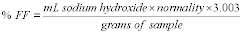 7. Method
Precision and Accuracy
7. Method
Precision and Accuracy
Test values should conform to the following statistical precision:
Variance = 0.005 Standard deviation = 0.07 95% Confidence Interval, for a single determination = 0.2 8. AuthorThis method was prepared by K. K. Tutin and M. L. Foster, Tacoma R&D Laboratory, Georgia-Pacific Resins, Inc. (Principle written by R. R. Conner.)
9. References9.1 GPAM 2221.2.
9.2 PR&C TM 2.035.
9.3 Project Report, Comparison of Free Formaldehyde Procedures, January 1990, K. K. Tutin.
Appendix C to Subpart NNN of Part 63 - Method for the Determination of Product Density
40:13.0.1.1.1.10.25.12.37 : Appendix C
Appendix C to Subpart NNN of Part 63 - Method for the Determination of Product Density 1. PurposeThe purpose of this test is to determine the product density of cured blanket insulation. The method is applicable to all cured board and blanket products.
2. EquipmentOne square foot (12 in. by 12 in.) template, or templates that are multiples of one square foot, for use in cutting insulation samples.
3. Procedure3.1 Obtain a sample at least 30 in. long across the machine width. Sample should be free of dirt or foreign matter.
3.2 Lay out the cutting pattern according to the plant's written procedure for the designated product.
3.2 Cut samples using one square foot (or multiples of one square foot) template.
3.3 Weigh product and obtain area weight (lb/ft 2).
3.4 Measure sample thickness.
3.5 Calculate the product density:
Density (lb/ft 3) = area weight (lb/ft 2)/thickness (ft)Table 1 to Subpart OOO of Part 63 - Applicability of General Provisions to Subpart OOO Affected Sources
40:13.0.1.1.1.11.25.21.38 :
Table 1 to Subpart OOO of Part 63 - Applicability of General Provisions to Subpart OOO Affected Sources| Reference | Applies to subpart OOO | Explanation |
|---|---|---|
| 63.1(a)(1) | Yes | § 63.1402 specifies definitions in addition to or that supersede definitions in § 63.2. |
| 63.1(a)(2) | Yes | |
| 63.1(a)(3) | Yes | § 63.1401(i) identifies those standards which overlap with the requirements of subpart OOO of this part and specify how compliance shall be achieved. |
| 63.1(a)(4) | Yes | Subpart OOO (this table) specifies the applicability of each paragraph in subpart A of this part. |
| 63.1(a)(5) | No | [Reserved]. |
| 63.1(a)(6) | Yes | |
| 63.1(a)(7)-63.1(a)(9) | No | [Reserved]. |
| 63.1(a)(10) | Yes | |
| 63.1(a)(11) | Yes | |
| 63.1(a)(12)-63.1(a)(14) | Yes | |
| 63.1(b)(1) | No | |
| 63.1(b)(2) | Yes | |
| 63.1(b)(3) | No | § 63.1400(e) provides documentation requirements for APPUs not considered affected sources. |
| 63.1(c)(1) | Yes | Subpart OOO (this table) specifies the applicability of each paragraph in subpart A of this part. |
| 63.1(c)(2) | No | Area sources are not subject to this subpart. |
| 63.1(c)(3) | No | [Reserved]. |
| 63.1(c)(4) | No | [Reserved]. |
| 63.1(c)(5) | Yes | Except that affected sources are not required to submit notifications overridden by this table. |
| 63.1(c)(6) | Yes | |
| 63.1(d) | No | [Reserved]. |
| 63.1(e) | Yes | |
| 63.2 | Yes | § 63.1402 specifies the definitions from subpart A of this part that apply to this subpart. |
| 63.3 | Yes | |
| 63.4(a)(1)-63.4(a)(3) | Yes | |
| 63.4(a)(4) | No | [Reserved]. |
| 63.4(a)(5) | Yes | |
| 63.4(b) | Yes | |
| 63.4(c) | Yes | |
| 63.5(a)(1) | Yes | Except the terms “source” and “stationary source” should be interpreted as having the same meaning as “affected source.” |
| 63.5(a)(2) | Yes | |
| 63.5(b)(1) | Yes | Except § 63.1400(d) specifies when construction or reconstruction is subject to new source standards. |
| 63.5(b)(2) | No | [Reserved]. |
| 63.5(b)(3) | Yes | |
| 63.5(b)(4) | Yes | Except that the Initial Notification and § 63.9(b) requirements do not apply. |
| 63.5(b)(5) | Yes | |
| 63.5(b)(6) | Yes | Except that § 63.1400(d) specifies when construction or reconstruction is subject to new source standards. |
| 63.5(c) | No | [Reserved]. |
| 63.5(d)(1)(i) | Yes | Except that the references to the Initial Notification and § 63.9(b)(5) do not apply. |
| 63.5(d)(1)(ii) | Yes | Except that § 63.5(d)(1)(ii)(H) does not apply. |
| 63.5(d)(1)(iii) | No | § 63.1417(e) specifies Notification of Compliance Status requirements. |
| 63.5(d)(2) | No | |
| 63.5(d)(3) | Yes | Except § 63.5(d)(3)(ii) does not apply, and equipment leaks subject to § 63.1410 are exempt. |
| 63.5(d)(4) | Yes | |
| 63.5(e) | Yes | |
| 63.5(f)(1) | Yes | |
| 63.5(f)(2) | Yes | Except that where § 63.9(b)(2) is referred to, the owner or operator need not comply. |
| 63.6(a) | Yes | |
| 63.6(b)(1) | Yes | |
| 63.6(b)(2) | Yes | |
| 63.6(b)(3) | Yes | |
| 63.6(b)(4) | Yes | |
| 63.6(b)(5) | Yes | |
| 63.6(b)(6) | No | [Reserved]. |
| 63.6(b)(7) | No | |
| 63.6(c)(1) | Yes | Except that § 63.1401 specifies the compliance date. |
| 63.6(c)(2) | No | |
| 63.6(c)(3) | No | [Reserved]. |
| 63.6(c)(4) | No | [Reserved]. |
| 63.6(c)(5) | Yes | |
| 63.6(d) | No | [Reserved]. |
| 63.6(e) | Yes | Except as otherwise specified in this table. |
| 63.6(e)(1)(i) | No | See § 63.1400(k)(4) for general duty requirement. |
| 63.6(e)(1)(ii) | No | |
| 63.6(e)(1)(iii) | Yes | |
| 63.6(e)(2) | Yes | |
| 63.6(e)(3) | No | |
| 63.6(f)(1) | No | |
| 63.6(f)(2) | Yes | Except § 63.7(c), as referred to in § 63.6(f)(2)(iii)(D), does not apply, and except that § 63.6(f)(2)(ii) does not apply to equipment leaks subject to § 63.1410. |
| 63.6(f)(3) | Yes | |
| 63.6(g) | Yes | |
| 63.6(h) | No | This subpart OOO does not require opacity and visible emission standards. |
| 63.6(i)(1) | Yes | |
| 63.6(i)(2) | Yes | |
| 63.6(i)(3) | Yes | |
| 63.6(i)(4)(i)(A) | Yes | |
| 63.6(i)(4)(i)(B) | No | Dates are specified in §§ 63.1401(e) and 63.1417(d)(1). |
| 63.6(i)(4)(ii) | No | |
| 63.6(i)(5)-(14) | Yes | |
| 63.6(i)(15) | No | [Reserved]. |
| 63.6(i)(16) | Yes | |
| 63.6(j) | Yes | |
| 63.7(a)(1) | Yes | |
| 63.7(a)(2) | No | § 63.1417(e) specifies the submittal dates of performance test results for all emission points except equipment leaks; for equipment leaks, compliance demonstration results are reported in the Periodic Reports. |
| 63.7(a)(3) | Yes | |
| 63.7(b) | No | § 63.1417 specifies notification requirements. |
| 63.7(c) | No | |
| 63.7(d) | Yes | |
| 63.7(e)(1) | No | See § 63.1413(a)(2). |
| 63.7(e)(2) | Yes | |
| 63.7(e)(3) | No | Subpart OOO specifies requirements. |
| 63.7(e)(4) | Yes | |
| 63.7(f) | Yes | Except that if a site specific test plan is not required, the notification deadline in § 63.7(f)(2)(i) shall be 60 days prior to the performance test, and in § 63.7(f)(3), approval or disapproval of the alternative test method shall not be tied to the site specific test plan. |
| 63.7(g) | Yes | Except that the requirements in § 63.1417(e) shall apply instead of the references to the Notification of Compliance Status report in § 63.9(h). In addition, equipment leaks subject to § 63.1410 are not required to conduct performance tests. |
| 63.7(h) | Yes | Except § 63.7(h)(4)(ii) may not be applicable, if the site-specific test plan in § 63.7(c)(2) is not required. |
| 63.8(a)(1) | Yes | |
| 63.8(a)(2) | No | |
| 63.8(a)(3) | No | [Reserved]. |
| 63.8(a)(4) | Yes | |
| 63.8(b)(1) | Yes | |
| 63.8(b)(2) | No | Subpart OOO specifies locations to conduct monitoring. |
| 63.8(b)(3) | Yes | |
| 63.8(c)(1) | Yes | |
| 63.8(c)(1)(i) | No | |
| 63.8(c)(1)(ii) | No | |
| 63.8(c)(1)(iii) | No | |
| 63.8(c)(2) | Yes | |
| 63.8(c)(3) | Yes | |
| 63.8(c)(4) | No | § 63.1415 specifies monitoring frequency; not applicable to equipment leaks because § 63.1410 does not require continuous monitoring systems. |
| 63.8(c)(5)-63.8(c)(8) | No | |
| 63.8(d) | No | |
| 63.8(e) | No | |
| 63.8(f)(1)-63.8(f)(3) | Yes | |
| 63.8(f)(4)(i) | No | Timeframe for submitting request is specified in § 63.1417 (j) or (k); not applicable to equipment leaks because § 63.1410 (through reference to 40 CFR part 63, subpart UU) specifies acceptable alternative methods. |
| 63.8(f)(4)(ii) | No | Contents of request are specified in § 63.1417(j) or (k). |
| 63.8(f)(4)(iii) | No | |
| 63.8(f)(5)(i) | Yes | |
| 63.8(f)(5)(ii) | No | |
| 63.8(f)(5)(iii) | Yes | |
| 63.8(f)(6) | No | Subpart OOO does not require continuous emission monitors. |
| 63.8(g) | No | Data reduction procedures specified in § 63.1416(a) and (h); not applicable to equipment leaks. |
| 63.9(a) | Yes | |
| 63.9(b) | No | Subpart OOO does not require an initial notification. |
| 63.9(c) | Yes | |
| 63.9(d) | Yes | |
| 63.9(e) | No | § 63.1417 specifies notification deadlines. |
| 63.9(f) | No | Subpart OOO does not require opacity and visible emission standards. |
| 63.9(g) | No | |
| 63.9(h) | No | § 63.1417(e) specifies Notification of Compliance Status requirements. |
| 63.9(i) | Yes | |
| 63.9(j) | Yes | For change in major source status only. |
| 63.9(k) | Yes | Only as specified in § 63.9(j). |
| 63.10(a) | Yes | |
| 63.10(b)(1) | No | § 63.1416(a) specifies record retention requirements. |
| 63.10(b)(2) | No | Subpart OOO specifies recordkeeping requirements. |
| 63.10(b)(3) | No | § 63.1400(e) requires documentation of sources that are not affected sources. |
| 63.10(c) | No | § 63.1416 specifies recordkeeping requirements. |
| 63.10(d)(1) | Yes | |
| 63.10(d)(2) | No | § 63.1417 specifies performance test reporting requirements; not applicable to equipment leaks. |
| 63.10(d)(3) | No | Subpart OOO does not require opacity and visible emission standards. |
| 63.10(d)(4) | Yes | |
| 63.10(d)(5) | No | See § 63.1417(g) for malfunction reporting requirements. |
| 63.10(e) | No | § 63.1417 specifies reporting requirements. |
| 63.10(f) | Yes | |
| 63.11 | Yes | Except that instead of § 63.11(b), § 63.1413(g) shall apply. |
| 63.12 | Yes | |
| 63.13-63.15 | Yes |
Table 2 to Subpart OOO of Part 63 - Known Organic Hazardous Air Pollutants (HAP) From the Manufacture of Amino/Phenolic Resins
40:13.0.1.1.1.11.25.21.39 :
Table 2 to Subpart OOO of Part 63 - Known Organic Hazardous Air Pollutants (HAP) From the Manufacture of Amino/Phenolic Resins| Organic HAP | CAS Number | Organic HAP subject to cooling tower monitoring requirements in § 63.1409 (Yes/No) | |
|---|---|---|---|
| Column A | Column B | ||
| Acrylamide | 79-06-1 | No | No |
| Aniline | 62-53-3 | Yes | No |
| Biphenyl | 92-52-4 | Yes | Yes |
| Cresol and cresylic acid (mixed) | 1319-77-3 | Yes | No |
| Cresol and cresylic acid (m-) | 108-39-4 | Yes | No |
| Cresol and cresylic acid (o-) | 95-48-7 | Yes | No |
| Cresol and cresylic acid (p-) | 106-44-5 | Yes | No |
| Diethanolamine | 111-42-2 | No | No |
| Dimethylformamide | 68-12-2 | No | No |
| Ethylbenzene | 100-41-4 | Yes | Yes |
| Ethylene glycol | 107-21-1 | No | No |
| Formaldehyde | 50-00-0 | Yes | No |
| Glycol ethers | 0 | No | No |
| Methanol | 67-56-1 | Yes | Yes |
| Methyl ethyl ketone | 78-93-3 | Yes | Yes |
| Methyl isobutyl ketone | 108-10-1 | Yes | Yes |
| Naphthalene | 91-20-3 | Yes | Yes |
| Phenol | 108-95-2 | Yes | No |
| Styrene | 100-42-5 | Yes | Yes |
| Toluene | 108-88-3 | No | Yes |
| Xylenes (NOS) | 1330-20-7 | Yes | Yes |
| Xylene (m-) | 108-38-3 | Yes | Yes |
| Xylene (o-) | 95-47-6 | Yes | Yes |
| Xylene (p-) | 106-42-3 | Yes | Yes |
CAS No. = Chemical Abstract Registry Number.
Table 3 to Subpart OOO of Part 63 - Batch Process Vent Monitoring Requirements
40:13.0.1.1.1.11.25.21.40 :
Table 3 to Subpart OOO of Part 63 - Batch Process Vent Monitoring Requirements| Control device | Parameters to be monitored | Frequency/recordkeeping requirements |
|---|---|---|
| Scrubber a | pH of scrubber effluent, and | Continuous records as specified in § 63.1416(d). b |
| Scrubber liquid and gas flow rates | Continuous records as specified in § 63.1416(d). b | |
| Absorber a | Exit temperature of the absorbing liquid, and | Continuous records as specified in § 63.1416(d). b |
| Exit specific gravity for the absorbing liquid | Continuous records as specified in § 63.1416(d). b | |
| Condenser a | Exit (product side) temperature | Continuous records as specified in § 63.1416(d). a |
| Carbon adsorber a | Total regeneration steam flow or nitrogen flow, or pressure (gauge or absolute) during carbon bed regeneration cycle(s), and | Record the total regeneration steam flow or nitrogen flow, or pressure for each carbon bed regeneration cycle. |
| Temperature of the carbon bed after regeneration and within 15 minutes of completing any cooling cycle(s) | Record the temperature of the carbon bed after each regeneration and within 15 minutes of completing any cooling cycle(s). | |
| Thermal incinerator | Firebox temperature c | Continuous records as specified in § 63.1416(d). b |
| Catalytic incinerator | Temperature upstream and downstream of the catalyst bed | Continuous records as specified in § 63.1416(d). b |
| Boiler or process heater with a design heat input capacity less than 44 megawatts and where the batch process vents or aggregate batch vent streams are not introduced with or used as the primary fuel | Firebox temperature c | Continuous records as specified in § 63.1416(d). b |
| Flare | Presence of a flame at the pilot light | Hourly records of whether the monitor was continuously operating during batch emission episodes, or portions thereof, selected for control and whether a flame was continuously present at the pilot light during said periods. |
| All control devices | Diversion to the atmosphere from the control device or | Hourly records of whether the flow indicator was operating during batch emission episodes, or portions thereof, selected for control and whether a diversion was detected at any time during said periods as specified in § 63.1416(d). |
| Monthly inspections of sealed valves | Records that monthly inspections were performed as specified in § 63.1416(d). | |
| Scrubber, absorber, condenser, and carbon adsorber (as an alternative to the requirements previously presented in this table) | Concentration level or reading indicated by an organic monitoring device at the outlet of the control device | Continuous records as specified in § 63.1416(d). b |
a Alternatively, these devices may comply with the organic monitoring device provisions listed at the end of this table.
b “Continuous records” is defined in § 63.111.
c Monitor may be installed in the firebox or in the ductwork immediately downstream of the firebox before any substantial heat exchange is encountered.
Table 4 to Subpart OOO of Part 63 - Operating Parameter Levels
40:13.0.1.1.1.11.25.21.41 :
Table 4 to Subpart OOO of Part 63 - Operating Parameter Levels| Device | Parameters to be monitored | Established operating parameter(s) |
|---|---|---|
| Scrubber | pH of scrubber effluent; and scrubber liquid and gas flow rates | Minimum pH; and minimum liquid/gas ratio |
| Absorber | Exit temperature of the absorbing liquid; and exit specific gravity of the absorbing liquid | Maximum temperature; and maximum specific gravity |
| Condenser | Exit temperature | Maximum temperature |
| Carbon absorber | Total regeneration steam or nitrogen flow, or pressure (gauge or absolute) a during carbon bed regeneration cycle; and temperature of the carbon bed after regeneration (and within 15 minutes of completing any cooling cycle(s)) | Maximum flow or pressure; and maximum temperature |
| Thermal incinerator | Firebox temperature | Minimum temperature |
| Catalytic incinerator | Temperature upstream and downstream of the catalyst bed | Minimum upstream temperature; and minimum temperature difference across the catalyst bed |
| Boiler or process heater | Firebox temperature | Minimum temperature |
| Other devices (or as an alternate to the requirements previously presented in this table) b | Organic HAP concentration level or reading at outlet of device | Maximum organic HAP concentration or reading |
a 25 to 50 mm (absolute) is a common pressure level obtained by pressure swing absorbers.
b Concentration is measured instead of an operating parameter.
Table 5 to Subpart OOO of Part 63 - Reports Required by This Subpart
40:13.0.1.1.1.11.25.21.42 :
Table 5 to Subpart OOO of Part 63 - Reports Required by This Subpart| Reference | Description of report | Due date |
|---|---|---|
| § 63.1400(j) and Subpart A of this part | Refer to Table 1 and Subpart A of this part | Refer to Subpart A of this part. |
| 63.1417(d) | Precompliance Report | Existing affected sources - 12 months prior to the compliance date. New affected sources - with application for approval of construction or reconstruction. |
| 63.1417(e) | Notification of Compliance Status | Within 150 days after the compliance date. |
| 63.1417(f) | Periodic Reports | Semiannually, no later than 60 days after the end of each 6-month period. See § 63.1417(f)(1) for the due date for the first report. |
| 63.1417(f)(12) | Quarterly reports upon request of the administrator | No later than 60 days after the end of each quarter. |
| 63.1417(g) | Start-up, shutdown, and malfunction reports | Semiannually (same schedule as Periodic reports). |
| 63.1417(h)(1) | Notification of storage vessel inspection | As specified in 40 CFR part 63, subpart WW. |
| 63.1417(h)(2) | Site-specific test plan | 90 days prior to planned date of test. |
| 63.1417(h)(3) | Notification of planned performance test | 30 days prior to planned date of test. |
| 63.1417(h)(4) | Notification of change in primary product | As specified in § 63.1400 (g)(7) or (g)(8). |
| 63.1417(h)(5) | Notification of added emission points | 180 days prior to the appropriate compliance date. |
| 63.1417(h)(6) | Notification that a small control device has been redesignated as a large control device | Within 60 days of the redesignation of control device size. |
| 63.1417(h)(7) | Notification of process change | Within 60 days after performance test or applicability assessment, whichever is sooner. |
| 63.1417(h)(8) | Electronic reporting | Within 60 days after completing performance test. |
a Note that the APPU remains subject to this subpart until the notification under § 63.1400(g)(7) is made.
Table 6 to Subpart OOO of Part 63 - Coefficients for Total Resource Effectiveness a
40:13.0.1.1.1.11.25.21.43 :
Table 6 to Subpart OOO of Part 63 - Coefficients for Total Resource Effectiveness a| Control device basis | Values of coefficients | ||
|---|---|---|---|
| A | B | C | |
| Flare | 5.276 × 10⁻¹ | 9.98 × 10⁻² | 2.096 × 10⁻³ |
| Thermal Incinerator 0 Percent Recovery | 4.068 × 10⁻¹ | 1.71 × 10⁻² | 8.664 × 10⁻³ |
| Thermal Incinerator 70 Percent Recovery | 6.868 × 10⁻¹ | 3.21 × 10⁻³ | 3.546 × 10⁻³ |
a Use according to procedures outlined in this section.
MJ/scm = MegaJoules per standard cubic meter.
scm/min = Standard cubic meters per minute.
Table 1 to Subpart PPP of Part 63 - Applicability of General Provisions to Subpart PPP Affected Sources
40:13.0.1.1.1.12.25.21.44 :
Table 1 to Subpart PPP of Part 63 - Applicability of General Provisions to Subpart PPP Affected Sources| Reference | Applies to subpart PPP |
Explanation |
|---|---|---|
| 63.1(a)(1) | Yes | § 63.1423 specifies definitions in addition to or that supersede definitions in § 63.2. |
| 63.1(a)(2) | Yes. | |
| 63.1(a)(3) | Yes | § 63.1422(f) through (k) of this subpart and § 63.160(b) identify those standards which overlap with the requirements of subparts PPP and H and specify how compliance shall be achieved. |
| 63.1(a)(4) | Yes | Subpart PPP (this table) specifies the applicability of each paragraph in subpart A to subpart PPP. |
| 63.1(a)(5) | No | Reserved. |
| 63.1(a)(6) | Yes. | |
| 63.1(a)(7)-(9) | No | Reserved. |
| 63.1(a)(10) | Yes. | |
| 63.1(a)(11) | Yes. | |
| 63.1(a)(12)-(14) | Yes. | |
| 63.1(b)(1) | No | § 63.1420(a) contains specific applicability criteria. |
| 63.1(b)(2) | Yes. | |
| 63.1(b)(3) | Yes. | |
| 63.1(c)(1) | Yes | Subpart PPP (this table) specifies the applicability of each paragraph in subpart A to subpart PPP. |
| 63.1(c)(2) | No | Area sources are not subject to subpart PPP. |
| 63.1(c)(3) | No | Reserved. |
| 63.1(c)(4) | No | Reserved. |
| 63.1(c)(5) | Yes | Except that affected sources are not required to submit notifications overridden by this table. |
| 63.1(c)(6) | Yes | |
| 63.1(d) | No | Reserved. |
| 63.1(e) | Yes. | |
| 63.2 | Yes | § 63.1423 specifies those subpart A definitions that apply to subpart PPP. |
| 63.3 | Yes. | |
| 63.4(a)(1)-(3) | Yes. | |
| 63.4(a)(4) | No | Reserved. |
| 63.4(a)(5) | Yes. | |
| 63.4(b) | Yes. | |
| 63.4(c) | Yes. | |
| 63.5(a)(1) | Yes | Except the terms “source” and “stationary source” should be interpreted as having the same meaning as “affected source.” |
| 63.5(a)(2) | Yes. | |
| 63.5(b)(1) | Yes | Except § 63.1420(g) defines when construction or reconstruction is subject to new source standards. |
| 63.5(b)(2) | No | Reserved. |
| 63.5(b)(3) | Yes. | |
| 63.5(b)(4) | Yes | Except that the initial notification requirements in § 63.1439(e)(3) shall apply instead of the requirements in § 63.9(b). |
| 63.5(b)(5) | Yes. | |
| 63.5(b)(6) | Yes | Except that § 63.1420(g) defines when construction or reconstruction is subject to the new source standards. |
| 63.5(c) | No | Reserved. |
| 63.5(d)(1)(i) | Yes. | |
| 63.5(d)(1)(ii) | Yes | Except that § 63.5(d)(1)(ii)(H) does not apply. |
| 63.5(d)(1)(iii) | No | § 63.1439(e)(5) and § 63.1434(e) specify notification of compliance status requirements. |
| 63.5(d)(2) | No. | |
| 63.5(d)(3) | Yes | Except § 63.5(d)(3)(ii) does not apply, and equipment leaks subject to § 63.1434 are exempt. |
| 63.5(d)(4) | Yes. | |
| 63.5(e) | Yes. | |
| 63.5(f)(1) | Yes. | |
| 63.5(f)(2) | Yes | Except that where § 63.9(b)(2) is referred to, the owner or operator need not comply. |
| 63.6(a) | Yes. | |
| 63.6(b)(1) | Yes. | |
| 63.6(b)(2) | Yes. | |
| 63.6(b)(3) | Yes. | |
| 63.6(b)(4) | Yes. | |
| 63.6(b)(5) | Yes. | |
| 63.6(b)(6) | No | Reserved. |
| 63.6(b)(7) | No. | |
| 63.6(c)(1) | Yes | § 63.1422 specifies the compliance date. |
| 63.6(c)(2) | No. | |
| 63.6(c)(3) | No | Reserved. |
| 63.6(c)(4) | No | Reserved. |
| 63.6(c)(5) | Yes. | |
| 63.6(d) | No | Reserved. |
| 63.6(e) | Yes | Except as otherwise specified for individual paragraphs. |
| § 63.6(e)(1)(i) | No | See § 63.1420(h)(4) for general duty requirement. |
| § 63.6(e)(1)(ii) | No. | |
| 63.6(e)(1)(iii) | Yes. | |
| 63.6(e)(2) | Yes. | |
| § 63.6(e)(3) | No. | |
| § 63.6(f)(1) | No. | |
| 63.6(f)(2) | Yes | Except 63.7(c), as referred to in § 63.6(f)(2)(iii)(D) does not apply, and except that § 63.6(f)(2)(ii) does not apply to equipment leaks subject to § 63.1434. |
| 63.6(f)(3) | Yes. | |
| 63.6(g) | Yes. | |
| 63.6(h) | No | Subpart PPP does not require opacity and visible emission standards. |
| 63.6(i)(1) | Yes. | |
| 63.6(i)(2) | Yes. | |
| 63.6(i)(3) | Yes. | |
| 63.6(i)(4)(i)(A) | Yes. | |
| 63.6(i)(4)(i)(B) | No | Dates are specified in § 63.1422(e) and § 63.1439(e)(4)(i) for all emission points except equipment leaks, which are covered under § 63.182(a)(6)(i). |
| 63.6(i)(4)(ii) | No. | |
| 63.6(i)(5)-(14) | Yes. | |
| 63.6(i)(15) | No | Reserved. |
| 63.6(i)(16) | Yes. | |
| 63.6(j) | Yes. | |
| 63.7(a)(1) | Yes. | |
| 63.7(a)(2) | No | § 63.1439(e) (5) and (6) specify the submittal dates of performance test results for all emission points except equipment leaks; for equipment leaks, compliance demonstration results are reported in the Periodic Reports. |
| 63.7(a)(3) | Yes. | |
| 63.7(b) | No | § 63.1437(a)(4) specifies notification requirements. |
| 63.7(c) | No | Except if the owner or operator chooses to submit an alternative nonopacity emission standard for approval under § 63.6(g). |
| 63.7(d) | Yes. | |
| 63.7(e)(1) | No | See § 63.1437(a). |
| 63.7(e)(2) | Yes. | |
| 63.7(e)(3) | No | Subpart PPP specifies requirements. |
| 63.7(e)(4) | Yes. | |
| 63.7(f) | Yes | Since a site-specific test plan is not required, the notification deadline in § 63.7(f)(2)(i) shall be 60 days prior to the performance test, and in § 63.7(f)(3) approval or disapproval of the alternative test method shall not be tied to the site-specific test plan. |
| 63.7(g) | Yes | Except the notification of compliance status report requirements in § 63.1439(e)(5) shall apply instead of those in § 63.9(h). In addition, equipment leaks subject to § 63.1434 are not required to conduct performance tests. |
| 63.7(h) | Yes | Except § 63.7(h)(4)(ii) is not applicable, since the site-specific test plans in § 63.7(c)(2) are not required. |
| 63.8(a)(1) | Yes. | |
| 63.8(a)(2) | No. | |
| 63.8(a)(3) | No | Reserved. |
| 63.8(a)(4) | Yes. | |
| 63.8(b)(1) | Yes. | |
| 63.8(b)(2) | No | Subpart PPP specifies locations to conduct monitoring. |
| 63.8(b)(3) | Yes. | |
| 63.8(c)(1) | Yes. | |
| 63.8(c)(1)(i) | No. | |
| 63.8(c)(1)(ii) | No. | |
| 63.8(c)(1)(iii) | No. | |
| 63.8(c)(2) | Yes. | |
| 63.8(c)(3) | Yes. | |
| 63.8(c)(4) | No | § 63.1438 specifies monitoring requirements; not applicable to equipment leaks, because § 63.1434 does not require continuous monitoring systems. |
| 63.8(c)(5)-(8) | No. | |
| 63.8(d) | No. | |
| 63.8(e) | No. | |
| 63.8(f)(1)-(3) | Yes. | |
| 63.8(f)(4)(i) | Yes | Except the timeframe for submitting request is specified in § 63.1439(f) or (g); not applicable to equipment leaks, because § 63.1434 (through subpart H of this part) specifies acceptable alternative methods. |
| 63.8(f)(4)(ii) | Yes. | |
| 63.8(f)(4)(iii) | Yes. | |
| 63.8(f)(5)(i) | Yes. | |
| 63.8(f)(5)(ii) | No. | |
| 63.8(f)(5)(iii) | Yes. | |
| 63.8(f)(6) | No | Subpart PPP does not require CEMs. |
| 63.8(g) | No | Data reduction procedures specified in § 63.1439(d) and (h); not applicable to equipment leaks. |
| 63.9(a) | Yes. | |
| 63.9(b) | No | The initial notification requirements are specified in § 63.1439(e)(3). |
| 63.9(c) | Yes. | |
| 63.9(d) | Yes. | |
| 63.9(e) | No | § 63.1437(a)(4) specifies notification deadline. |
| 63.9(f) | No | Subpart PPP does not require opacity and visible emission standards. |
| 63.9(g) | No. | |
| 63.9(h) | No | § 63.1439(e)(5) specifies notification of compliance status requirements. |
| 63.9(i) | Yes. | |
| 63.9(j) | Yes | For change in major source status only. |
| 63.9(k) | Yes | Only as specified in § 63.9(j). |
| 63.10(a) | Yes. | |
| 63.10(b)(1) | No | § 63.1439(a) specifies record retention requirements. |
| 63.10(b)(2) | No | Subpart PPP specifies recordkeeping requirements. |
| 63.10(b)(3) | Yes. | |
| 63.10(c) | No | § 63.1439 specifies recordkeeping requirements. |
| 63.10(d)(1) | Yes. | |
| 63.10(d)(2) | No | § 63.1439(e)(5) and (6) specify performance test reporting requirements; not applicable to equipment leaks. |
| 63.10(d)(3) | No | Subpart PPP does not require opacity and visible emission standards. |
| 63.10(d)(4) | Yes. | |
| 63.10(d)(5) | No | See § 63.1439(b)(1)(ii) for malfunction reporting requirements. |
| 63.10(e) | No | § 63.1439 specifies reporting requirements. |
| 63.10(f) | Yes. | |
| 63.11 | Yes. | |
| 63.12 | Yes | Except that the authority of § 63.177 (for equipment leaks) will not be delegated to States. |
| 63.13-63.15 | Yes. |
Table 2 to Subpart PPP of Part 63 - Applicability of HON Provisions to Subpart PPP Affected Sources
40:13.0.1.1.1.12.25.21.45 :
Table 2 to Subpart PPP of Part 63 - Applicability of HON Provisions to Subpart PPP Affected Sources| Reference | Applies to subpart PPP | Explanation | Applicable section of subpart PPP |
|---|---|---|---|
| Subpart F: | |||
| 63.100 | No | ||
| 63.101 | Yes | Several definitions from 63.101 are referenced at 63.1423 | 63.1423. |
| 63.102-63.103 | No | ||
| 63.104 | Yes | With the differences noted in 63.1435(b) through (d) | 63.1435. |
| 63.105 | Yes | With the differences noted in 63.1433(b) | 63.1433. |
| 63.106 | No | ||
| Subpart G: | |||
| 63.107 | No | ||
| 63.110 | No | ||
| 63.111 | Yes | Several definitions from 63.111 are incorporated by reference into 63.1423 | 63.1423. |
| 63.112 | No | ||
| 63.113-63.118 | Yes | For THF facilities, with the differences noted in 63.1425(f)(1) through (f)(10) | 63.1425. |
| No | For epoxide facilities, except that 63.115(d) is used for TRE determinations | 63.1428. | |
| 63.119-63.123 | Yes | With the differences noted in 63.1432(b) through 63.1432(p) | 63.1432. |
| 63.124-63.125 | No | Reserved | |
| 63.126-63.130 | No | ||
| 63.131 | No | Reserved | |
| 63.132-63.147 | Yes | With the differences noted in 63.1433(a)(1) through 63.1433(a)(19) | 63.1433. |
| 63.148-63.149 | Yes | With the differences noted in 63.1432(b) through 63.1432(p) and 63.1433(a)(1) through 63.1433(a)(19) | 63.1432 and 63.1433. |
| 63.150 | No | ||
| 63.151-63.152 | No | ||
| 63.153 | No | 63.1421 | |
| Subpart H: | |||
| 63.160-63.182 | Yes | Subpart PPP affected sources shall comply with all requirements of subpart H, with the differences noted in 63.1422(d), 63.1422(h), and 63.1434 | 63.1434 |
| Subpart U: | |||
| 63.480-63.487 | No | ||
| 63.488 | Yes | Portions of 63.488(b) and (e) are cross-referenced in subpart PPP. | |
| 63.489-63.506 | No |
Table 3 to Subpart PPP of Part 63 - Group 1 Storage Vessels at Existing and New Affected Sources
40:13.0.1.1.1.12.25.21.46 :
Table 3 to Subpart PPP of Part 63 - Group 1 Storage Vessels at Existing and New Affected Sources| Vessel capacity (cubic meters) |
Vapor Pressure
a (kilopascals) |
|---|---|
| 75 ≤capacity <151 | ≥13.1 |
| capacity ≥151 | ≥5.2 |
a Maximum true vapor pressure of total organic HAP at storage temperature.
Table 4 to Subpart PPP of Part 63 - Known Organic HAP From Polyether Polyol Products
40:13.0.1.1.1.12.25.21.47 :
Table 4 to Subpart PPP of Part 63 - Known Organic HAP From Polyether Polyol Products| Organic HAP/chemical name [CAS No.] |
|---|
| 1,3 Butadiene |
| (106990) |
| Epichlorohydrin |
| (106898) |
| Ethylene Oxide |
| (75218) |
| n-Hexane |
| (110543) |
| Methanol |
| (67561) |
| Propylene Oxide |
| (75569) |
| Toluene |
| (108883) |
CAS No. = Chemical Abstracts Service Registry Number.
Table 5 to Subpart PPP of Part 63 - Process Vents From Batch Unit Operations - Monitoring, Recordkeeping, and Reporting Requirements
40:13.0.1.1.1.12.25.21.48 :
Table 5 to Subpart PPP of Part 63 - Process Vents From Batch Unit Operations - Monitoring, Recordkeeping, and Reporting Requirements| Control technique | Parameter to be monitored | Recordkeeping and reporting requirements for monitored parameters |
|---|---|---|
| Thermal Incinerator | Firebox temperature a | 1. Continuous records as specified in § 63.1429. b |
| 2. Record and report the average firebox temperature measured during the performance test - NCS. c | ||
| 3. Record the daily average firebox temperature as specified in § 63.1429. | ||
| 4. Report all daily average temperatures that are below the minimum operating temperature established in the NCS or operating permit and all instances when monitoring data are not collected - PR. d e | ||
| Catalytic Incinerator | Temperature upstream and downstream of the catalyst bed | 1. Continuous records as
specified in § 63.1429. b 2. Record and report the average upstream and downstream temperatures and the average temperature difference across the catalyst bed measured during the performance test - NCS. c |
| 3. Record the daily average upstream temperature and temperature difference across catalyst bed as specified in § 63.1429. | ||
| 4. Report all daily average upstream temperatures that are below the minimum upstream temperature established in the NCS or operating permit - PR. d e | ||
| 5. Report all daily average temperature differences across the catalyst bed that are below the minimum difference established in the NCS or operating permit - PR. d e | ||
| 6. Report all instances when monitoring data are not collected. e | ||
| Boiler or Process Heater with a design heat input capacity less than 44 megawatts and where the process vents are not introduced with or used as the primary fuel | Firebox temperature a | 1. Continuous records as
specified in § 63.1429. b 2. Record and report the average firebox temperature measured during the performance test - NCS c 3. Record the daily average firebox temperature as specified in § 63.1429. d 4. Report all daily average temperatures that are below the minimum operating temperature established in the NCS or operating permit and all instances when monitoring data are not collected - PR. d e |
| Flare | Presence of a flame at the pilot light | 1. Hourly records of whether the monitor was continuously operating during batch emission episodes selected for control and whether a flame was continuously present at the pilot light during each hour. |
| 2. Record and report the presence of a flame at the pilot light over the full period of the compliance determination - NCS. c | ||
| 3. Record the times and durations of all periods during batch emission episodes when all flames at the pilot light of a flare are absent or the monitor is not operating. | ||
| 4. Report the times and durations of all periods during batch emission episodes selected for control when all flames at the pilot light of a flare are absent - Pr. d | ||
| Absorber f | Liquid flow rate into or out of the scrubber, or the pressure drop across the scrubber | 1. Records every 15 minutes,
as specified in § 63.1429. b 2. Record and report the average liquid flow rate into or out of the scrubber, or the pressure drop across the scrubber, measured during the performance test - NCS. |
| 3. Record the liquid flow rate into or out of the scrubber, or the pressure drop across the scrubber, every 15 minutes, as specified in § 63.1429. | ||
| 4. Report all scrubber flow rates or pressure drop values that are below the minimum operating value established in the NCS or operating permit and all instances when monitoring data are not collected - PR. d e | ||
| pH of the scrubber | 1. Once daily records as specified in § 63.1429. b | |
| 2. Record and report the average pH of the scrubber effluent measured during the performance test - NCS. c | ||
| 3. Record at least once daily the pH of the scrubber effluent. | ||
| 4. Report all pH scrubber effluent readings out of the range established in the NCS or operating permit and all instances when monitoring data are not collected - PR. d e If a base absorbent is used, report all pH values that are below the minimum operating values. If an acid absorbent is used, report all pH values that are above the maximum operating values. | ||
| Condenser f | Exit (product side) temperature | 1. Continuous records as specified in § 63.1429. b |
| 2. Record and report the average exit temperature measured during the performance test - NCS. | ||
| 3. Record the daily average exit temperature as specified in § 63.1429. | ||
| 4. Report all daily average exit temperatures that are above the maximum operating temperature established in the NCS or operating permit and all instances when monitoring data are not collected - PR. d e | ||
| Carbon Adsorber f | Total regeneration stream mass or volumetric flow during carbon bed regeneration cycle(s), and | 1. Record of total
regeneration stream mass or volumetric flow for each carbon bed
regeneration cycle. 2. Record and report the total regeneration stream mass or volumetric flow during each carbon bed regeneration cycle during the performance test - NCS. c |
| 3. Report all carbon bed regeneration cycles when the total regeneration stream mass or volumetric flow is above the maximum flow rate established in the NCS or operating permit - PR. d e | ||
| Temperature of the carbon bed after regeneration and within 15 minutes of completing any cooling cycle(s) | 1. Record the temperature of
the carbon bed after each regeneration and within 15 minutes of
completing any cooling cycle(s). 2. Record and report the temperature of the carbon bed after each regeneration and within 15 minutes of completing any cooling cycle(s) measured during the performance test - NCS. c |
|
| 3. Report all carbon bed regeneration cycles when the temperature of the carbon bed after regeneration, or within 15 minutes of completing any cooling cycle(s), is above the maximum temperature established in the NCS or operating permit - PR. d e | ||
| Absorber, Condenser, and Carbon Adsorber (as an alternative to the above) | Concentration level or reading indicated by an organic monitoring device at the outlet of the recovery device | 1. Continuous records as
specified in § 63.1429. b 2. Record and report the average concentration level or reading measured during the performance test - NCS. 3. Record the daily average concentration level or reading as specified in § 63.1429. |
| 4. Report all daily average concentration levels or readings that are above the maximum concentration or reading established in the NCS or operating permit and all instances when monitoring data are not collected - PR. d e | ||
| All Combustion, recovery, or recapture devices | Diversion to the atmosphere from the combustion, recovery, or recapture device or | 1. Hourly records of whether
the flow indicator was operating during batch emission episodes
selected for control and whether a diversion was detected at any
time during the hour, as specified in § 63.1429. 2. Record and report the times of all periods during batch emission episodes selected for control when emissions are diverted through a bypass line, or the flow indicator is not operating - PR. d |
| Monthly inspections of sealed valves | 1. Records that monthly
inspections were performed as specified in § 63.1429. 2. Record and report all monthly inspections that show that valves are in the diverting position or that a seal has been broken - PR. d |
|
| ECO | Time from the end of the epoxide feed, or the epoxide partial pressure in the reactor or direct measurement of epoxide concentration in the reactor liquid at the end of the ECO | 1. Records at the end of each
batch, as specified in § 63.1427(i). 2. Record and report the average parameter value of the parameters chosen, measured during the performance test. 3. Record the batch cycle ECO duration, epoxide partial pressure, or epoxide concentration in the liquid at the end of the ECO 4. Report all batch cycle parameter values outside of the ranges established in accordance with § 63.1427(i)(3) and all instances when monitoring data were not collected - PR. d e |
a Monitor may be installed in the firebox or in the ductwork immediately downstream of the firebox before any substantial heat exchange is encountered.
b “Continuous records” is defined in § 63.111.
c NCS = Notification of Compliance Status described in § 63.1429.
d PR = Periodic Reports described in § 63.1429.
e The periodic reports shall include the duration of periods when monitoring data are not collected as specified in § 63.1439.
f Alternatively, these devices may comply with the organic monitoring device provisions listed at the end of this table.
Table 6 to Subpart PPP of Part 63 - Process Vents From Continuous Unit Operations - Monitoring, Recordkeeping, and Reporting Requirements
40:13.0.1.1.1.12.25.21.49 :
Table 6 to Subpart PPP of Part 63 - Process Vents From Continuous Unit Operations - Monitoring, Recordkeeping, and Reporting Requirements| Control technique | Parameter to be monitored | Recordkeeping and reporting requirements for monitored parameters |
|---|---|---|
| Thermal Incinerator | Firebox temperature a | 1. Continuous records as
specified in § 63.1429. b 2. Record and report the average firebox temperature measured during the performance test - NCS. c |
| 3. Record the daily average firebox temperature for each operating day. | ||
| 4. Report all daily average temperatures that are below the minimum operating temperature established in the NCS or operating permit and all instances when sufficient monitoring data are not collected - PR. d e | ||
| Catalytic Incinerator | Temperature upstream and downstream of the catalyst bed | 1. Continuous records as
specified in § 63.1429. b 2. Record and report the average upstream and downstream temperatures and the average temperature difference across the catalyst bed measured during the performance test - NCS c |
| 3. Record the daily average upstream temperature and temperature difference across catalyst bed for each operating day. | ||
| 4. Report all daily average upstream temperatures that are below the minimum upstream temperature established in the NCS or operating permit - PR. d e | ||
| 5. Report all daily average temperature differences across the catalyst bed that are below the minimum difference established in the NCS or operating permit - PR. d e | ||
| 6. Report all operating days when insufficient monitoring data are collected. e | ||
| Boiler or Process Heater with a design heat input capacity less than 44 megawatts and where the process vents are not introduced with or used as the primary fuel | Firebox temperature a | 1. Continuous records as
specified in § 63.1429. b 2. Record and report the average firebox temperature measured during the performance test - NCS c 3. Record the daily average firebox temperature for each operating day. d 4. Report all daily average temperatures that are below the minimum operating temperature established in the NCS or operating permit and all instances when insufficient monitoring data are collected - PR. d e |
| Flare | Presence of a flame at the pilot light | 1. Hourly records of whether
the monitor was continuously operating and whether a flame was
continuously present at the pilot light during each hour. 2. Record and report the presence of a flame at the pilot light over the full period of the compliance determination - NCS. c |
| 3. Record the times and durations of all periods when all flames at the pilot light of a flare are absent or the monitor is not operating. | ||
| 4. Report the times and durations of all periods when all flames at the pilot light of a flare are absent - Pr. d | ||
| Absorber f | Exit temperature of the absorbing liquid, and | 1. Continuous records as
specified in § 63.1429. b 2. Record and report the exit temperature of the absorbing liquid averaged over the full period of the TRE determination - NCS. c |
| 3. Record the daily average exit temperature of the absorbing liquid for each operating day. | ||
| 4. Report all the daily average exit temperatures of the absorbing liquid that are below the minimum operating value established in the NCS or operating - PR. d e | ||
| Exit specific gravity for the absorbing liquid | 1. Continuous records as
specified in § 63.1429. b 2. Record and report the exit specific gravity averaged over the full period of the TRE determination - NCS. |
|
| 3. Record the daily average exit specific gravity for each operating day. | ||
| 4. Report all daily average exit specific gravity values that are below the minimum operating value established in the NCS or operating - PR. d e | ||
| Condenser f | Exit (product side) temperature | 1. Continuous records as
specified in § 63.1429. b 2. Record and report the exit temperature averaged over the full period of the TRE determination - NCS. |
| 3. Record the daily average exit temperature for each operating day. | ||
| 4. Report all daily average exit temperatures that are above the maximum operating temperature established in the NCS or operating - PR. d e | ||
| Carbon Adsorber f | Total regeneration stream mass or volumetric flow during carbon bed regeneration cycle(s), and | 1. Record of total
regeneration stream mass or volumetric flow for each carbon bed
regeneration cycle. 2. Record and report the total regeneration stream mass or volumetric flow during each carbon bed regeneration cycle during the period of the TRE determination - NCS. c |
| 3. Report all carbon bed regeneration cycles when the total regeneration stream mass or volumetric flow is above the maximum flow rate established in the NCS or operating permit - PR. d e | ||
| Temperature of the carbon bed after regeneration and within 15 minutes of completing any cooling cycle(s) | 1. Record the temperature of
the carbon bed after each regeneration and within 15 minutes of
completing any cooling cycle(s). 2. Record and report the temperature of the carbon bed after each regeneration during the period of the TRE determination - NCS c |
|
| 3. Report all carbon bed regeneration cycles when the temperature of the carbon bed after regeneration is above the maximum temperature established in the NCS or operating permit - PR. d e | ||
| Absorber, Condenser, and Carbon Adsorber (as an alternative to the above) | Concentration level or reading indicated by an organic monitoring device at the outlet of the recovery device | 1. Continuous records as
specified in § 63.1429. b 2. Record and report the concentration level or reading averaged over the full period of the TRE determination - NCS. 3. Record the daily average concentration level or reading for each operating day. |
| 4. Report all daily average concentration levels or readings that are above the maximum concentration or reading established in the NCS or operating - PR. d e | ||
| All Combustion, recovery, or recapture devices | Diversion to the atmosphere from the combustion, recovery, or recapture device or | 1. Hourly records of whether
the flow indicator was operating and whether a diversion was
detected at any time during each hour. 2. Record and report the times of all periods when the vent stream is diverted through a bypass line, or the flow indicator is not operating - PR. d |
| Monthly inspections of sealed valves | 1. Records that monthly
inspections were performed as specified in § 63.1429. 2. Record and report all monthly inspections that show that valves are in the diverting position or that a seal has been broken - PR. d |
a Monitor may be installed in the firebox or in the ductwork immediately downstream of the firebox before any substantial heat exchange is encountered.
b “Continuous records” is defined in § 63.111.
c NCS = Notification of Compliance Status described in § 63.1429.
d PR = Periodic Reports described in § 63.1429.
e The periodic reports shall include the duration of periods when monitoring data are not collected as specified in § 63.1439.
f Alternatively, these devices may comply with the organic monitoring device provisions listed at the end of this table.
Table 7 to Subpart PPP of Part 63 - Operating Parameters for Which Monitoring Levels Are Required To Be Established for Process Vent Streams
40:13.0.1.1.1.12.25.21.50 :
Table 7 to Subpart PPP of Part 63 - Operating Parameters for Which Monitoring Levels Are Required To Be Established for Process Vent Streams| Control technique | Parameters to be monitored | Established operating parameter(s) |
|---|---|---|
| Thermal incinerator | Firebox temperature | Minimum temperature. |
| Catalytic incinerator | Temperature upstream and downstream of the catalyst bed | Minimum upstream temperature; and minimum temperature difference across the catalyst bed. |
| Boiler or process heater | Firebox temperature | Minimum temperature. |
| Absorber | Liquid flow rate or pressure drop; and pH of scrubber effluent, if an acid or base absorbent is used | Minimum flow rate or pressure drop; and maximum pH if an acid absorbent is used, or minimum pH if a base absorbent is used. |
| Condenser | Exit temperature | Maximum temperature. |
| Carbon adsorber | Total regeneration stream mass or volumetric flow during carbon bed regeneration cycle; and temperature of the carbon bed after regeneration (and within 15 minutes of completing any cooling cycle(s)) | Maximum mass or volumetric flow; and maximum temperature. |
| Extended Cookout (ECO) | Time from the end of the epoxide feed to the end of the ECO, or the reactor epoxide partial pressure at the end of the ECO, or the epoxide concentration in the reactor liquid at the end of the ECO | Minimum duration, or maximum partial pressure at the end of ECO, or maximum epoxide concentration in the reactor liquid at the end of ECO. |
| Other devices (or as an alternate to the above). a | HAP concentration level or reading at outlet of device | Maximum HAP concentration or reading. |
a Concentration is measured instead of an operating parameter.
Table 8 to Subpart PPP of Part 63 - Routine Reports Required by This Subpart
40:13.0.1.1.1.12.25.21.51 :
Table 8 to Subpart PPP of Part 63 - Routine Reports Required by This Subpart| Reference | Description of report | Due date |
|---|---|---|
| § 63.1439(b) and subpart A of this part | Refer to § 63.1439(b), Table 1 of this subpart, and to subpart A of this part | Refer to subpart A of this part. |
| § 63.1439(e)(3) | Initial notification | New affected sources w/
initial start-up at least 90 days after June 1, 1999: submit the
application for approval of construction or reconstruction in lieu
of the initial notification report. New affected sources w/ initial start-up prior to 90 days after June 1, 1999:by 90 days after June 1, 1999. |
| § 63.1439(e)(4) | Precompliance Report a | Existing affected sources: 12
months prior to compliance date. New affected sources: with the application for approval of construction or reconstruction. |
| § 63.1439(e)(5) | Notification of Compliance Status b | Within 150 days after the compliance date. |
| § 63.1439(e)(6) | Periodic Reports | Semiannually, no later than 60 days after the end of each 6-month period. See § 63.1439(e)(6)(i) for the due date for this report. |
| § 63.1439(e)(6)(iii) | Quarterly reports for sources with excursions (upon request of the Administrator) | No later than 60 days after the end of each quarter. |
| § 63.506(e)(7)(i) | Storage Vessels Notification of Inspection | At least 30 days prior to the refilling of each storage vessel or the inspection of each storage vessel. |
a There may be two versions of this report due at different times; one for equipment subject to § 63.1434 and one for other emission points subject to this subpart.
b There will be two versions of this report due at different times; one for equipment subject to § 63.1434 and one for other emission points subject to this subpart.
Table 1 to Subpart QQQ of Part 63 - Applicability of General Provisions to Subpart QQQ
40:14.0.1.1.1.1.210.21.1 :
Table 1 to Subpart QQQ of Part 63 - Applicability of General Provisions to Subpart QQQAs required in § 63.1457, you must comply with the requirements of the NESHAP General Provisions (40 CFR part 63, subpart A) shown in the following table:
| Citation | Subject | Applies to subpart QQQ | Explanation |
|---|---|---|---|
| § 63.1 | Applicability | Yes | |
| § 63.2 | Definitions | Yes | |
| § 63.3 | Units and Abbreviations | Yes | |
| § 63.4 | Prohibited Activities | Yes | |
| § 63.5 | Construction and Reconstruction | Yes | |
| § 63.6(a)-(g) | Compliance with Standards and Maintenance requirements | Yes | |
| § 63.6(h) | Determining compliance with Opacity and VE standards | No | Subpart QQQ specifies the requirements and test protocol used to determine compliance with the opacity limits. |
| § 63.6(i)-(j) | Extension of Compliance and Presidential Compliance Exemption | Yes | |
| § 63.7(a)(1)-(2) | Applicability and Performance Test Dates | No | Subpart QQQ specifies performance test applicability and dates. |
| § 63.7(a)(3), (b)-(h) | Performance Testing Requirements | Yes | |
| § 63.8 except for (a)(4),(c)(4), and (f)(6) | Monitoring Requirements | Yes | |
| § 63.8(a)(4) | Additional Monitoring Requirements for Control devices in § 63.11 | No | Subpart QQ does not require flares. |
| § 63.8(c)(4) | Continuous Monitoring System Requirements | No | Subpart QQQ specifies requirements for operation of CMS. |
| § 63.8(f)(6) | RATA Alternative | No | Subpart QQQ does not require continuous emission monitoring systems. |
| § 63.9 | Notification Requirements | Yes | |
| § 63.9(g)(5) | DATA reduction | No | Subpart QQQ specifies data reduction requirements |
| § 63.10 except for (b)(2)(xiii) and (c)(7)-(8) | Recordkeeping and reporting Requirements | Yes | |
| § 63.10(b)(2)(xiii) | CMS Records for RATA Alternative | No | Subpart QQQ does not require continuous emission monitoring systems. |
| § 63.10(c)(7)-(8) | Records of Excess Emissions and Parameter Monitoring Accedences for CMS | No | Subpart QQQ specifies record keeping requirements |
| § 63.11 | Control Device Requirements | No | Subpart QQQ does not require flares |
| § 63.12 | State Authority and Delegations | Yes | |
| §§ 63.13-63.15 | Addresses, Incorporation by Reference, Availability of Information | Yes |
Figure 1 to Subpart QQQ of Part 63 - Data Summary Sheet for Determination of Average Opacity
40:14.0.1.1.1.1.210.21.2 :
Figure 1 to Subpart QQQ of Part 63 - Data Summary Sheet for Determination of Average Opacity| Clock time | Number of converters blowing | Converter aisle activity | Average opacity for 1-minute
interval (percent) |
Visible emissions
interference observed during 1-minute interval? (yes or no) |
Average opacity for 1-minute
interval blowing without visible emission interferences (percent) |
|---|---|---|---|---|---|
Table 1 to Subpart RRR of Part 63 - Emission Standards for New and Existing Affected Sources
40:14.0.1.1.1.2.215.20.3 :
Table 1 to Subpart RRR of Part 63 - Emission Standards for New and Existing Affected Sources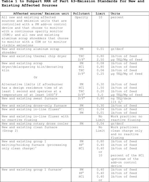
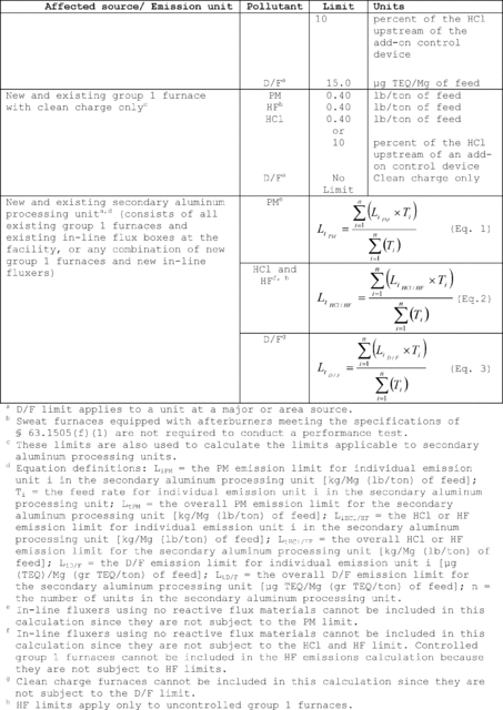 [81 FR 38089, June
13, 2016]
[81 FR 38089, June
13, 2016]Table 2 to Subpart RRR of Part 63 - Summary of Operating Requirements for New and Existing Affected Sources and Emission Units
40:14.0.1.1.1.2.215.20.4 :
Table 2 to Subpart RRR of Part 63 - Summary of Operating Requirements for New and Existing Affected Sources and Emission Units| Affected source/emission unit | Monitor type/operation/process | Operating requirements |
|---|---|---|
| All affected sources and emission units with an add-on air pollution control device | Emission capture and collection system | Design and install in accordance with ACGIH Guidelines; e operate in accordance with OM&M plan (sweat furnaces may be operated according to 63.1506(c)(4)). b |
| All affected sources and emission units subject to production-based (lb/ton of feed) emission limits a | Charge/feed weight or Production weight | Operate a device that records the weight of each charge; Operate in accordance with OM&M plan. b |
| Group 1 furnace, group 2 furnace, in-line fluxer and scrap dryer/delacquering kiln/decoating kiln | Labeling | Identification, operating parameter ranges and operating requirements posted at affected sources and emission units; control device temperature and residence time requirements posted at scrap dryer/delacquering kiln/decoating kiln. |
| Aluminum scrap shredder with fabric filter | Bag leak detector or | Initiate corrective action within 1-hr of alarm and complete in accordance with OM&M plan b; operate such that alarm does not sound more than 5% of operating time in 6-month period. |
| COM or | Initiate corrective action within 1-hr of a 6-minute average opacity reading of 5% or more and complete in accordance with OM&M plan. b | |
| VE | Initiate corrective action within 1-hr of any observed VE and complete in accordance with the OM&M plan. b | |
| Thermal chip dryer with afterburner | Afterburner operating temperature | Maintain average temperature for each 3-hr period at or above average operating temperature during the performance test. |
| Afterburner operation | Operate in accordance with OM&M plan. b | |
| Feed material | Operate using only unpainted aluminum chips. | |
| Scrap dryer/delacquering kiln/decoating kiln with afterburner and lime-injected fabric filter | Afterburner operating temperature | Maintain average temperature for each 3-hr period at or above average operating temperature during the performance test. |
| Afterburner operation | Operate in accordance with OM&M plan. b | |
| Bag leak detector or | Initiate corrective action within 1-hr of alarm and complete in accordance with the OM&M plan; b operate such that alarm does not sound more than 5% of operating time in 6-month period. | |
| COM | Initiate corrective action within 1-hr of a 6-minute average opacity reading of 5% or more and complete in accordance with the OM&M plan. b | |
| Fabric filter inlet temperature | Maintain average fabric filter inlet temperature for each 3-hr period at or below average temperature during the performance test +14 °C (+25 °F). | |
| Lime injection rate | Maintain free-flowing lime in the feed hopper or silo at all times for continuous injection systems; maintain feeder setting at or above the level established during the performance test for continuous injection systems. | |
| Sweat furnace with afterburner | Afterburner operating temperature | If a performance test was conducted, maintain average temperature for each 3-hr period at or above average operating temperature during the performance test; if a performance test was not conducted, and afterburner meets specifications of § 63.1505(f)(1), maintain average temperature for each 3-hr period at or above 1600 °F. |
| Afterburner operation | Operate in accordance with OM&M plan. b | |
| Dross-only furnace with fabric filter | Bag leak detector or | Initiate corrective action within 1-hr of alarm and complete in accordance with the OM&M plan; b operate such that alarm does not sound more than 5% of operating time in 6-month period. |
| COM | Initiate corrective action within 1-hr of a 6-minute average opacity reading of 5% or more and complete in accordance with the OM&M plan. b | |
| Feed/charge material | Operate using only dross as the feed material. | |
| Rotary dross cooler with fabric filter | Bag leak detector or | Initiate corrective action within 1-hr of alarm and complete in accordance with the OM&M plan; b operate such that alarm does not sound more than 5% of operating time in 6-month period. |
| COM | Initiate corrective action within 1-hr of a 6-minute average opacity reading of 5% or more and complete in accordance with the OM&M plan. b | |
| In-line fluxer with lime-injected fabric filter (including those that are part of a secondary aluminum processing unit) | Bag leak detector or | Initiate corrective action within 1-hr of alarm and complete in accordance with the OM&M plan; b operate such that alarm does not sound more than 5% of operating time in 6-month period. |
| COM | Initiate corrective action within 1-hr of a 6-minute average opacity reading of 5% or more and complete in accordance with the OM&M plan. b | |
| Lime injection rate | Maintain free-flowing lime in the feed hopper or silo at all times for continuous injection systems; maintain feeder setting at or above the level established during performance test for continuous injection systems. | |
| Reactive flux injection rate | Maintain reactive flux injection rate at or below rate used during the performance test for each operating cycle or time period used in the performance test. | |
| In-line fluxer (using no reactive flux material) | Flux materials | Use no reactive flux. |
| Group 1 furnace with lime-injected fabric filter (including those that are part of a secondary of aluminum processing unit) | Bag leak detector or | Initiate corrective action within 1-hr of alarm; operate such that alarm does not sound more than 5% of operating time in 6-month period; complete corrective action in accordance with the OM&M plan. b |
| COM | Initiate corrective action within 1-hr of a 6-minute average opacity reading of 5% or more; complete corrective action in accordance with the OM&M plan. b | |
| Fabric filter inlet temperature | Maintain average fabric filter inlet temperature for each 3-hour period at or below average temperature during the performance test +14 °C (+25 °F). | |
| Natural gas-fired, propane-fired or electrically heated group 1 furnaces that will be idled for at least 24 hours | Operation of associated capture/collection systems and APCD b may be temporarily stopped. Operation of these capture/collection systems and control devices must be restarted before feed/charge, flux or alloying materials are added to the furnace. | |
| Reactive flux injection rate | Maintain reactive flux injection rate (kg/Mg) (lb/ton) at or below rate used during the performance test for each furnace cycle. | |
| Lime injection rate | Maintain free-flowing lime in the feed hopper or silo at all times for continuous injection systems; maintain feeder setting at or above the level established at performance test for continuous injection systems. | |
| Maintain molten aluminum level | Operate sidewell furnaces such that the level of molten metal is above the top of the passage between sidewell and hearth during reactive flux injection, unless the hearth is also controlled. | |
| Fluxing in sidewell furnace hearth | Add reactive flux only to the sidewell of the furnace unless the hearth is also controlled. | |
| Group 1 furnace without add-on air pollution controls (including those that are part of a secondary aluminum processing unit) | Reactive flux injection rate | Maintain the total reactive chlorine flux injection rate and total reactive fluorine flux injection rate for each operating cycle or time period used in the performance test at or below the average rate established during the performance test. |
| Clean (group 2) furnace | Charge and flux materials | Use only clean charge. Use no reactive flux. |
a Thermal chip dryers, scrap dryers/delacquering kilns/decoating kilns, dross-only furnaces, in-line fluxers and group 1 furnaces including melting/holding furnaces.
b OM&M plan - Operation, maintenance, and monitoring plan.
c Site-specific monitoring plan. Owner/operators of group 1 furnaces without add-on APCD must include a section in their OM&M plan that documents work practice and pollution prevention measures, including procedures for scrap inspection, by which compliance is achieved with emission limits and process or feed parameter-based operating requirements. This plan and the testing to demonstrate adequacy of the monitoring plan must be developed in coordination with and approved by the permitting authority for major sources, or the Administrator for area sources.
d APCD - Air pollution control device.
e Incorporated by reference, see § 63.14.
Table 3 to Subpart RRR of Part 63 - Summary of Monitoring Requirements for New and Existing Affected Sources and Emission Units
40:14.0.1.1.1.2.215.20.5 :
Table 3 to Subpart RRR of Part 63 - Summary of Monitoring Requirements for New and Existing Affected Sources and Emission Units| Affected source/Emission unit | Monitor type/Operation/Process | Monitoring requirements |
|---|---|---|
| All affected sources and emission units with an add-on air pollution control device | Emission capture and collection system | Annual inspection of all emission capture, collection, and transport systems to ensure that systems continue to operate in accordance with ACGIH Guidelines. e Inspection includes volumetric flow rate measurements or verification of a permanent total enclosure using EPA Method 204. d |
| All affected sources and emission units subject to production-based (lb/ton or gr/ton of feed/charge) emission limits. a | Feed/charge weight | Record weight of each feed/charge, weight measurement device or other procedure accuracy of ±1%; b calibrate according to manufacturer's specifications, or at least once every 6 months. |
| Group 1 furnace, group 2 furnace, in-line fluxer, and scrap dryer/delacquering kiln/decoating kiln | Labeling | Check monthly to confirm that labels are intact and legible. |
| Aluminum scrap shredder with fabric filter | Bag leak detector or | Install and operate in accordance with manufacturer's operating instructions. |
| COM or | Design and install in accordance with PS-1; collect data in accordance with subpart A of 40 CFR part 63; determine and record 6-minute block averages. | |
| VE | Conduct and record results of 30-minute daily test in accordance with Method 9 or ASTM D7520-13. e | |
| Thermal chip dryer with afterburner | Afterburner operating temperature | Continuous measurement device to meet specifications in § 63.1510(g)(1); record average temperature for each 15-minute block; determine and record 3-hr block averages. |
| Afterburner operation | Annual inspection of afterburner internal parts; complete repairs in accordance with the OM&M plan. | |
| Feed/charge material | Record identity of each feed/charge; certify feed/charge materials every 6 months. | |
| Scrap dryer/delacquering kiln/decoating kiln with afterburner and lime-injected fabric filter | Afterburner operating temperature | Continuous measurement device to meet specifications in § 63.1510(g)(1); record temperature for each 15-minute block; determine and record 3-hr block averages. |
| Afterburner operation | Annual inspection of afterburner internal parts; complete repairs in accordance with the OM&M plan. | |
| Bag leak detector or | Install and operate in accordance with manufacturer's operating instructions. | |
| COM | Design and Install in accordance with PS-1; collect data in accordance with subpart A of 40 CFR part 63; determine and record 6-minute block averages. | |
| Lime injection rate | For continuous injection systems, inspect each feed hopper or silo every 8 hours to verify that lime is free flowing; record results of each inspection. If blockage occurs, inspect every 4 hours for 3 days; return to 8-hour inspections if corrective action results in no further blockage during 3-day period, record feeder setting daily. Verify monthly that lime injection rate is no less than 90 percent of the rate used during the compliance demonstration test. | |
| Fabric filter inlet temperature | Continuous measurement device to meet specifications in § 63.1510(h)(2); record temperatures in 15-minute block averages; determine and record 3-hr block averages. | |
| Sweat furnace with afterburner | Afterburner operating temperature | Continuous measurement device to meet specifications in § 63.1510(g)(1); record temperatures in 15-minute block averages; determine and record 3-hr block averages. |
| Afterburner operation | Annual inspection of afterburner internal parts; complete repairs in accordance with the OM&M plan. | |
| Dross-only furnace with fabric filter | Bag leak detector or | Install and operate in accordance with manufacturer's operating instructions. |
| COM | Design and install in accordance with PS-1; collect data in accordance with subpart A of 40 CFR part 63; determine and record 6-minute block averages. | |
| Feed/charge material | Record identity of each feed/charge; certify charge materials every 6 months. | |
| Rotary dross cooler with fabric filter | Bag leak detector or | Install and operate in accordance with manufacturer's operating instructions. |
| COM | Design and install in accordance with PS-1; collect data in accordance with subpart A of 40 CFR part 63; determine and record 6-minute block averages. | |
| In-line fluxer with lime-injected fabric filter | Bag leak detector or | Install and operate in accordance with manufacturer's operating instructions. |
| COM | Design and install in accordance with PS-1; collect data in accordance with subpart A of 40 CFR part 63; determine and record 6-minute block averages. | |
| Reactive flux injection rate | Weight measurement device accuracy of ±1%; b calibrate according to manufacturer's specifications or at least once every 6 months; record time, weight and type of reactive flux added or injected for each 15-minute block period while reactive fluxing occurs; calculate and record total reactive chlorine flux injection rate and the total reactive fluorine flux injection rate for each operating cycle or time period used in performance test; or Alternative flux injection rate determination procedure per § 63.1510(j)(5). For solid flux added intermittently, record the amount added for each operating cycle or time period used in the performance test. | |
| In-line fluxer using no reactive flux | Flux materials | Record flux materials; certify every 6 months for no reactive flux. |
| Group 1 furnace with lime-injected fabric filter | Bag leak detector or | Install and operate in accordance with manufacturer's operating instructions. |
| COM | Design and install in accordance with PS-1; collect data in accordance with subpart A of 40 part CFR 63; determine and record 6-minute block averages. | |
| Lime injection rate | For continuous injection systems, record feeder setting daily and inspect each feed hopper or silo every 8 hours to verify that lime is free-flowing; record results of each inspection. If blockage occurs, inspect every 4 hours for 3 days; return to 8-hour inspections if corrective action results in no further blockage during 3-day period. c Verify monthly that the lime injection rate is no less than 90 percent of the rate used during the compliance demonstration test. | |
| Reactive flux injection rate | Weight measurement device accuracy of ±1%; b calibrate every 3 months; record weight and type of reactive flux added or injected for each 15-minute block period while reactive fluxing occurs; calculate and record total reactive chlorine flux injection rate and the total reactive fluorine flux injection rate for each operating cycle or time period used in performance test; or Alternative flux injection rate determination procedure per § 63.1510(j)(5). For solid flux added intermittently, record the amount added for each operating cycle or time period used in the performance test. | |
| Group 1 furnace without add-on controls | Fluxing in sidewell furnace hearth | Maintain flux addition operating log; certify every 6 months. |
| Reactive flux injection rate | Weight measurement device accuracy of +1%; b calibrate according to manufacturer's specifications or at least once every six months; record weight and type of reactive flux added or injected for each 15-minute block period while reactive fluxing occurs; calculate and record total reactive flux injection rate for each operating cycle or time period used in performance test. For solid flux added intermittently, record the amount added for each operating cycle or time period used in the performance test. | |
| OM&M plan (approved by permitting agency) | Demonstration of site-specific monitoring procedures to provide data and show correlation of emissions across the range of charge and flux materials and furnace operating parameters. | |
| Feed material (melting/holding furnace) | Record type of permissible feed/charge material; certify charge materials every 6 months. | |
| Clean (group 2) furnace | Charge and flux materials | Record charge and flux materials; certify every 6 months for clean charge and no reactive flux. |
a Thermal chip dryers, scrap dryers/delacquering kilns/decoating kilns, dross-only furnaces, in-line fluxers and group 1 furnaces or melting/holding furnaces.
b Permitting agency may approve measurement devices of alternative accuracy, for example in cases where flux rates are very low and costs of meters of specified accuracy are prohibitive; or where feed/charge weighing devices of specified accuracy are not practicable due to equipment layout or charging practices.
c Permitting authority for major sources, or the Administrator for area sources may approve other alternatives including load cells for lime hopper weight, sensors for carrier gas pressure, or HCl monitoring devices at fabric filter outlet.
d The frequency of volumetric flow rate measurements may be decreased to once every 5 years if daily differential pressure measures, daily fan RPM, or daily fan motor amp measurements are made in accordance with § 63.1510(d)(2)(ii)-(iii). The frequency of annual verification of a permanent total enclosure may be decreased to once every 5 years if negative pressure measurements in the enclosure are made daily in accordance with § 63.1510(d)(2)(iv). In lieu of volumetric flow rate measurements or verification of permanent total enclosure, sweat furnaces may demonstrate annually negative air flow into the sweat furnace opening in accordance with § 63.1510(d)(3).
e Incorporated by reference, see § 63.14.
Appendix A to Subpart RRR of Part 63 - General Provisions Applicability to Subpart RRR
40:14.0.1.1.1.2.215.20.6 : Appendix A
Appendix A to Subpart RRR of Part 63 - General Provisions Applicability to Subpart RRR| Citation | Requirement | Applies to RRR | Comment |
|---|---|---|---|
| § 63.1(a)(1)-(4) | General Applicability | Yes | |
| § 63.1(a)(5) | No | [Reserved] | |
| § 63.1(a)(6) | Yes | ||
| § 63.1(a)(7)-(9) | No | [Reserved] | |
| § 63.1(a)(10)-(12) | Yes | ||
| § 63.1(b) | Initial Applicability Determination | Yes | EPA retains approval authority. |
| § 63.1(c)(1) | Applicability After Standard Established | Yes | |
| § 63.1(c)(2) | Yes | § 63.1500(e) exempts area sources subject to this subpart from the obligation to obtain Title V operating permits. | |
| § 63.1(c)(3)-(4) | No | [Reserved] | |
| § 63.1(c)(5) | Yes | ||
| § 63.1(c)(6) | Reclassification | Yes | |
| § 63.1(d) | No | [Reserved] | |
| § 63.1(e) | Applicability of Permit Program | Yes | |
| § 63.2 | Definitions | Yes | Additional definitions in § 63.1503. |
| § 63.3 | Units and Abbreviations | Yes | |
| § 63.4(a)(1)-(2) | Prohibited Activities | Yes | |
| § 63.4(a)(3)-(5) | No | [Reserved] | |
| § 63.4(b) | Circumvention | Yes | |
| § 63.4(c) | Fragmentation | Yes | |
| § 63.5(a) | Applicability of Preconstruction Review and Notification | Yes | |
| § 63.5(b)(1) | Requirements for Existing, Newly, Constructed Sources and Reconstructed Sources | Yes | |
| § 63.5(b)(2) | No | [Reserved] | |
| § 63.5(b)(3)-(4) | Yes | ||
| § 63.5(b)(5) | No | [Reserved] | |
| § 63.5(b)(6) | Yes | ||
| § 63.5(c) | No | [Reserved] | |
| § 63.5(d) | Application for Approval of Construction or Reconstruction | Yes | |
| § 63.5(e) | Approval of Construction or Reconstruction | Yes | |
| § 63.5(f) | Approval of Construction or Reconstruction Based on Prior State Preconstruction Review | Yes | |
| § 63.6(a) | Applicability for Compliance with Standards and Maintenance Requirements | Yes | |
| § 63.6(b)(1)-(5) | Compliance Dates for New and Reconstructed Sources | Yes | § 63.1501 specifies dates. |
| § 63.6(b)(6) | No | [Reserved] | |
| § 63.6(b)(7) | Yes | ||
| § 63.6(c)(1) | Compliance Dates for Existing Sources | Yes | § 63.1501 specifies dates. |
| § 63.6(c)(2) | Yes | ||
| § 63.6(c)(3)-(4) | No | [Reserved] | |
| § 63.6(c)(5) | Yes | ||
| § 63.6(d) | No | [Reserved] | |
| § 63.6(e)(1)(i) | Operation and Maintenance Requirements | No | See § 63.1506(a)(5) for general duty requirement. Any other cross reference to § 63.6(3)(1)(i) in any other general provision referenced shall be treated as a cross reference to § 63.1506(a)(5). |
| § 63.6(e)(1)(ii) | No | ||
| § 63.6(e)(2) | No | [Reserved] | |
| § 63.6(e)(3) | Startup, Shutdown, and Malfunction Plan | No | |
| § 63.6(f)(1) | Compliance with Nonopacity Emission Standards | No | |
| § 63.6(f)(2) | Yes | ||
| § 63.6(g) | Use of an Alternative Nonopacity Emission Standard | No | |
| § 63.6(h)(1) | Applicability for Compliance with Opacity and Visible Emission Standards | No | |
| § 63.6(h)(2) | Methods for Determining Compliance | Yes | |
| § 63.6(h)(3) | No | [Reserved] | |
| § 63.6(h)(4)-(9) | Yes | ||
| § 63.6(i)(1)-(14) | Extension of Compliance | Yes | |
| § 63.6(i)(15) | No | [Reserved] | |
| § 63.6(i)(16) | Yes | ||
| § 63.6(j) | Exemption from Compliance | Yes | |
| § 63.7(a) | Applicability and Performance Test Dates | Yes | Except § 63.1511 establishes dates for initial performance tests. |
| § 63.7(b) | Notification of Performance Test | Yes | |
| § 63.7(c) | Quality Assurance Program | Yes | |
| § 63.7(d) | Performance Testing Facilities | Yes | |
| § 63.7(e)(1) | Conduct of Performance Tests | No | |
| § 63.7(e)(2) | Yes | ||
| § 63.7(e)(3) | Yes | ||
| § 63.7(f) | Use of an Alternative Test Method | Yes | |
| § 63.7(g)(1)-(3) | Data Analysis, Recordkeeping, and Reporting | Yes | Except for § 63.7(g)(2), which is reserved. |
| § 63.7(h)(1)-(5) | Waiver of Performance Tests | Yes | |
| § 63.8(a)(1) | Applicability for Monitoring Requirements | Yes | |
| § 63.8(a)(2) | Yes | ||
| § 63.8(a)(3) | No | [Reserved] | |
| § 63.8(a)(4) | Yes | ||
| § 63.8(b) | Conduct of Monitoring | Yes | |
| § 63.8(c)(1)(i) | Operation and Maintenance of Continuous Monitoring Systems (CMS) | No | See § 63.1506(a)(5) for general duty requirement. |
| § 63.8(c)(1)(ii) | Yes | ||
| § 63.8(c)(1)(iii) | No | ||
| § 63.8(c)(2)-(8) | Yes | ||
| § 63.8(d)(1)-(2) | Quality Control Program | Yes | |
| § 63.8(d)(3) | Yes, except for last sentence, which refers to an SSM plan. SSM plans are not required | ||
| § 63.8(e) | Performance Evaluation of CMS | Yes | |
| § 63.8(f)(1)-(5) | Use of an Alternative Monitoring Method | No | § 63.1501(w) includes provisions for monitoring alternatives. |
| § 63.8(f)(6) | Alternative to the Relative Accuracy Test | Yes | |
| § 63.8(g)(1) | Reduction of Monitoring Data | Yes | |
| § 63.8(g)(2) | No | § 63.1512 requires five 6-minute averages for an aluminum scrap shredder. | |
| § 63.8(g)(3)-(5) | Yes | ||
| § 63.9(a) | Applicability and General Information for Notification Requirements | Yes | |
| § 63.9(b)(1)-(5) | Initial Notifications | Yes | Except § 63.9(b)(3) is reserved. |
| § 63.9(c) | Request for Compliance Extension | Yes | |
| § 63.9(d) | Notification that Source is Subject to Special Compliance Requirements | Yes | |
| § 63.9(e) | Notification of Performance Test | Yes | |
| § 63.9(f) | Notification of Opacity and Visible Emission Observations | Yes | |
| § 63.9(g) | Additional Notification Requirement for Sources with CMS | Yes | |
| § 63.9(h)(1)-(3) | Notification of Compliance Status | Yes | Except § 63.1515 establishes dates notification of compliance status reports. |
| § 63.9(h)(4) | No | [Reserved] | |
| § 63.9(h)(5)-(6) | Yes | ||
| § 63.9(i) | Adjustment of Deadlines for Required Communications | Yes | |
| § 63.9(j) | Change in Information Already Provided | Yes | |
| § 63.9(k) | Electronic reporting procedures | Yes | Only as specified in § 63.9(j). |
| § 63.10(a) | Applicability and General Information for Recordkeeping and Reporting Requirements | Yes | |
| § 63.10(b)(1) | General Recordkeeping Requirements | Yes | |
| § 63.10(b)(2)(i), (ii), (iv), (v) | No | ||
| § 63.10(b)(2)(iii), (vi)-(xiv) | Yes | § 63.1517 includes additional requirements. | |
| § 63.10(b)(3) | Recordkeeping Requirement for Applicability Determinations | Yes | |
| § 63.10(c)(1) | Additional Recordkeeping Requirements for Sources with CMS | Yes | |
| § 63.10(c)(2)-(4) | No | [Reserved] | |
| § 63.10(c)(5) | Yes | ||
| § 63.10(c)(6) | Yes | ||
| § 63.10(c)(7)-(8) | Yes | ||
| § 63.10(c)(9) | No | [Reserved] | |
| § 63.10(c)(10)-(13) | Yes | ||
| § 63.10(c)(14) | Yes | ||
| § 63.10(c)(15) | No | ||
| § 63.10(d)(1) | General Reporting Requirements | Yes | |
| § 63.10(d)(2) | Reporting Results of Performance Tests | Yes | |
| § 63.10(d)(3) | Reporting Results of Opacity or Visible Emission Observations | Yes | |
| § 63.10(d)(4) | Progress Reports | No | See § 63.1516(d). |
| § 63.10(d)(5) | Periodic Startup, Shutdown, and Malfunction Reports | No | See § 63.1516(d). |
| § 63.10(e)(1)-(2) | Additional Reporting Requirements for Sources with CMS | Yes | |
| § 63.10(e)(3) | Excess Emissions and CMS Performance Report and Summary Report | Yes | Reporting deadline given in § 63.1516. |
| § 63.10(e)(4) | Continuous Opacity Monitoring System (COMS) Data Produced During a Performance Test | Yes | |
| § 63.10(f) | Waiver of Recordkeeping or Reporting Requirements | Yes | |
| § 63.11(a)-(e) | Control Device and Work Practice Requirements | No | Flares not applicable. |
| § 63.12(a)-(c) | State Authority and Delegations | Yes | EPA retains authority for applicability determinations. |
| § 63.13 | Addresses | Yes | |
| § 63.14 | Incorporations by Reference | Yes | ACGIH Guidelines, ASTM D7520-13, and Interim Procedures for Estimating Risks Associated with Exposures to Mixtures of Chlorinated Dibenzo-p-Dioxins and -Dibenzofurans (CDDs and CDFs) and 1989 Update. |
| § 63.15 | Availability of Information and Confidentiality | Yes | |
| § 63.16 | Performance Track Provisions | No |
Table 1 to Subpart TTT of Part 63 - General Provisions Applicability to Subpart TTT
40:14.0.1.1.1.4.215.12.7 :
Table 1 to Subpart TTT of Part 63 - General Provisions Applicability to Subpart TTT| Reference | Applies to subpart TTT |
Comment |
|---|---|---|
| 63.6(a), (b), (c) | Yes. | |
| 63.6(d) | No | Section reserved. |
| 63.6(e)(1)(i) | No | See 63.1543(i) and 63.1544(d) for general duty requirement. |
| 63.6(e)(1)(ii) | No. | |
| 63.6(e)(1)(iii) | Yes. | |
| 63.6(e)(2) | No | Section reserved. |
| 63.6(e)(3) | No. | |
| 63.6(f)(1) | No. | |
| 63.6(g) | Yes. | |
| 63.6(h) | No | No opacity limits in rule. |
| 63.6(i) | Yes. | |
| 63.6(j) | Yes. | |
| § 63.7(a)-(d) | Yes. | |
| § 63.7(e)(1) | No | See 63.1546(c). |
| § 63.7(e)(2)-(e)(4) | Yes. | |
| 63.7(f), (g), (h) | Yes. | |
| 63.8(a)-(b) | Yes. | |
| 63.8(c)(1)(i) | No. | |
| 63.8(c)(1)(ii) | Yes. | |
| 63.8(c)(1)(iii) | No. | |
| 63.8(c)(2)-(d)(2) | Yes. | |
| 63.8(d)(3) | Yes, except for last sentence. | |
| 63.8(e)-(g) | Yes. | |
| 63.9(a), (b), (c), (e), (g), (h)(1) through (3), (h)(5) and (6), (i) and (j) | Yes. | |
| 63.9(f) | No. | |
| 63.9(h)(4) | No | Reserved. |
| 63.9(k) | Yes | Only as specified in 63.9(j). |
| 63.10(b)(2)(i) | No. | |
| 63.10(b)(2)(ii) | No | See 63.1549(b)(9) and (10) for recordkeeping of occurrence and duration of malfunctions and recordkeeping of actions taken during malfunction. |
| 63.10(b)(2)(iii) | Yes. | |
| 63.10(b)(2)(iv)-(b)(2)(v) | No. | |
| 63.10(b)(2)(vi)-(b)(2)(xiv) | Yes. | |
| 63.(10)(b)(3) | Yes. | |
| 63.10(c)(1)-(9) | Yes. | |
| 63.10(c)(10)-(11) | No | See 63.1549(b)(9) and (10) for recordkeeping of malfunctions. |
| 63.10(c)(12)-(c)(14) | Yes. | |
| 63.10(c)(15) | No. | |
| 63.10(d)(1)-(4) | Yes. | |
| 63.10(d)(5) | No | See 63.1549(e)(9) for reporting of malfunctions. |
| 63.10(e)-(f) | Yes. |
Table 1 to Subpart UUU of Part 63 - Metal HAP Emission Limits for Catalytic Cracking Units
40:14.0.1.1.1.5.220.21.8 :
Table 1 to Subpart UUU of Part 63 - Metal HAP Emission Limits for Catalytic Cracking UnitsAs stated in § 63.1564(a)(1), you shall meet each emission limitation in the following table that applies to you.
| For each new or existing catalytic cracking unit . . . | You shall meet the following
emission limits for each catalyst regenerator vent . . . |
|---|---|
| 1. Subject to new source performance standard (NSPS) for PM in 40 CFR 60.102 and not electing § 60.100(e) | PM emissions must not exceed 1.0 gram per kilogram (g/kg) (1.0 lb/1,000 lb) of coke burn-off, and the opacity of emissions must not exceed 30 percent, except for one 6-minute average opacity reading in any 1-hour period. Before August 1, 2017, if the discharged gases pass through an incinerator or waste heat boiler in which you burn auxiliary or in supplemental liquid or solid fossil fuel, the incremental rate of PM emissions must not exceed 43.0 grams per Gigajoule (g/GJ) or 0.10 pounds per million British thermal units (lb/million Btu) of heat input attributable to the liquid or solid fossil fuel; and the opacity of emissions must not exceed 30 percent, except for one 6-minute average opacity reading in any 1-hour period. |
| 2. Subject to NSPS for PM in 40 CFR 60.102a(b)(1)(i); or 40 CFR 60.102 and electing § 60.100(e) | PM emissions must not exceed 1.0 g/kg (1.0 lb PM/1,000 lb) of coke burn-off or, if a PM CEMS is used, 0.040 grain per dry standard cubic feet (gr/dscf) corrected to 0 percent excess air. |
| 3. Subject to NSPS for PM in 40 CFR 60.102a(b)(1)(ii) | PM emissions must not exceed 0.5 g/kg coke burn-off (0.5 lb/1000 lb coke burn-off) or, if a PM CEMS is used, 0.020 gr/dscf corrected to 0 percent excess air. |
| 4. Option 1a: Elect NSPS subpart J requirements for PM per coke burn limit and 30% opacity, not subject to the NSPS for PM in 40 CFR 60.102 or 60.102a(b)(1) | PM emissions must not exceed the limits specified in Item 1 of this table. |
| 5. Option 1b: Elect NSPS subpart Ja requirements for PM per coke burn-off limit, not subject to the NSPS for PM in 40 CFR 60.102 or 60.102a(b)(1) | PM emissions must not exceed 1.0 g/kg (1.0 lb PM/1000 lb) of coke burn-off. |
| 6. Option 1c: Elect NSPS subpart Ja requirements for PM concentration limit, not subject to the NSPS for PM in 40 CFR 60.102 or 60.102a(b)(1) | PM emissions must not exceed 0.040 gr/dscf corrected to 0 percent excess air. |
| 7. Option 2: PM per coke burn-off limit, not subject to the NSPS for PM in 40 CFR 60.102 or 60.102a(b)(1) | PM emissions must not exceed 1.0 g/kg (1.0 lb PM/1000 lb) of coke burn-off in the catalyst regenerator. |
| 8. Option 3: Ni lb/hr limit, not subject to the NSPS for PM in 40 CFR 60.102 or 60.102a(b)(1) | Nickel (Ni) emissions must not exceed 13,000 milligrams per hour (mg/hr) (0.029 lb/hr). |
| 9. Option 4: Ni per coke burn-off limit, not subject to the NSPS for PM in 40 CFR 60.102 or 60.102a(b)(1) | Ni emissions must not exceed 1.0 mg/kg (0.001 lb/1,000 lb) of coke burn-off in the catalyst regenerator. |
Table 2 to Subpart UUU of Part 63 - Operating Limits for Metal HAP Emissions From Catalytic Cracking Units
40:14.0.1.1.1.5.220.21.9 :
Table 2 to Subpart UUU of Part 63 - Operating Limits for Metal HAP Emissions From Catalytic Cracking UnitsAs stated in § 63.1564(a)(2), you shall meet each operating limit in the following table that applies to you.
| For each new or existing catalytic cracking unit . . . | For this type of
continuous monitoring system . . . |
For this type of control device . . . |
You shall meet this
operating limit . . . |
|---|---|---|---|
| 1. Subject to the NSPS for PM in 40 CFR 60.102 and not elect § 60.100(e) | Continuous opacity monitoring system | Any | On and after August 1, 2017, maintain the 3-hour rolling average opacity of emissions from your catalyst regenerator vent no higher than 20 percent. |
| 2. Subject to NSPS for PM in 40 CFR 60.102a(b)(1)(i) or electing § 60.100(e) | a. PM CEMS | Any | Not applicable. |
| b. Continuous opacity monitoring system used to comply with a site-specific opacity limit | Cyclone or electrostatic precipitator | Maintain the 3-hour rolling average opacity of emissions from your catalyst regenerator vent no higher than the site-specific opacity limit established during the performance test. | |
| c. Continuous parameter monitoring systems | Electrostatic precipitator | i. Maintain the daily average coke burn-off rate or daily average flow rate no higher than the limit established in the performance test. | |
| ii. Maintain the 3-hour rolling average total power and secondary current above the limit established in the performance test. | |||
| d. Continuous parameter monitoring systems | Wet scrubber | i. Maintain the 3-hour rolling average liquid-to-gas ratio above the limit established in the performance test. | |
| ii. Except for periods of startup, shutdown, and hot standby, maintain the 3-hour rolling average pressure drop above the limit established in the performance test. 1 | |||
| e. Bag leak detection (BLD) system | Fabric filter | Maintain particulate loading below the BLD alarm set point established in the initial adjustment of the BLD system or allowable seasonal adjustments. | |
| 3. Subject to NSPS for PM in 40 CFR 60.102a(b)(1)(ii) | Any | Any | The applicable operating limits in Item 2 of this table. |
| 4. Option 1a: Elect NSPS subpart J requirements for PM per coke burn limit, not subject to the NSPS for PM in 40 CFR 60.102 or 60.102a(b)(1) | Any | Any | See Item 1 of this table. |
| 5. Option 1b: Elect NSPS subpart Ja requirements for PM per coke burn-off limit, not subject to the NSPS for PM in 40 CFR 60.102 or 60.102a(b)(1) | Any | Any | The applicable operating limits in Item 2.b, 2.c, 2.d, and 2.e of this table. |
| 6. Option 1c: Elect NSPS subpart Ja requirements for PM concentration limit, not subject to the NSPS for PM in 40 CFR 60.102 or 60.102a(b)(1) | PM CEMS | Any | Not applicable. |
| 7. Option 2: PM per coke burn-off limit not subject to the NSPS for PM in 40 CFR 60.102 or 60.102a(b)(1) | a. Continuous opacity monitoring system used to comply with a site-specific opacity limit | Cyclone, fabric filter, or electrostatic precipitator | See Item 2.b of this table. Alternatively, before August 1, 2017, you may maintain the hourly average opacity of emissions from your catalyst generator vent no higher than the site-specific opacity limit established during the performance test. |
| b. Continuous parameter monitoring systems | i. Electrostatic precipitator | (1) See Item 2.c.i of this
table. (2) See item 2.c.ii of this table. Alternatively, before August 1, 2017, you may maintain the daily average voltage and secondary current above the limit established in the performance test. |
|
| ii. Wet scrubber | (1) See Item 2.d.i of this
table. Alternatively, before August 1, 2017, you may maintain the
daily average liquid-to-gas ratio above the limit established in
the performance test. (2) See Item 2.d.ii of the table. Alternatively, before August 1, 2017, you may maintain the daily average pressure drop above the limit established in the performance test (not applicable to a wet scrubber of the non-venturi jet-ejector design). |
||
| c. Bag leak detection (BLD) system | Fabric filter | See item 2.e of this table. | |
| 8. Option 3: Ni lb/hr limit not subject to the NSPS for PM in 40 CFR 60.102 | a. Continuous opacity monitoring system | Cyclone, fabric filter, or electrostatic precipitator | Maintain the 3-hour rolling average Ni operating value no higher than the limit established during the performance test. Alternatively, before August 1, 2017, you may maintain the daily average Ni operating value no higher than the limit established during the performance test. |
| b. Continuous parameter monitoring systems | i. Electrostatic precipitator | (1) See Item 2.c.i of this
table. (2) Maintain the monthly rolling average of the equilibrium catalyst Ni concentration no higher than the limit established during the performance test. |
|
| (3) See Item 2.c.ii of this table. Alternatively, before August 1, 2017, you may maintain the daily average voltage and secondary current (or total power input) above the established during the performance test. | |||
| ii. Wet scrubber | (1) Maintain the monthly rolling average of the equilibrium catalyst Ni concentration no higher than the limit established during the performance test. | ||
| (2) See Item 2.d.i of this table. Alternatively, before August 1, 2017, you may maintain the daily average liquid-to-gas ratio above the limit established during the performance test. | |||
| (3) See Item 2.d.ii of this table. Alternatively, before August 1, 2017, you may maintain the daily average pressure drop above the limit established during the performance test (not applicable to a non-venturi wet scrubber of the jet-ejector design). | |||
| c. Bag leak detection (BLD) system | Fabric filter | See item 2.e of this table. | |
| 9. Option 4: Ni per coke burn-off limit not subject to the NSPS for PM in 40 CFR 60.102 | a. Continuous opacity monitoring system | Cyclone, fabric filter, or electrostatic precipitator | Maintain the 3-hour rolling average Ni operating value no higher than Ni operating limit established during the performance test. Alternatively, before August 1, 2017, you may elect to maintain the daily average Ni operating value no higher than the Ni operating limit established during the performance test. |
| b. Continuous parameter monitoring systems | i. Electrostatic precipitator | (1) Maintain the monthly rolling average of the equilibrium catalyst Ni concentration no higher than the limit established during the performance test. | |
| (2) See Item 2.c.ii of this table. Alternatively, before August 1, 2017, you may maintain the daily average voltage and secondary current (or total power input) above the limit established during the performance test. | |||
| ii. Wet scrubber | (1) Maintain the monthly rolling average of the equilibrium catalyst Ni concentration no higher than the limit established during the performance test. | ||
| (2) See Item 2.d.i of this table. Alternatively, before August 1, 2017, you may maintain the daily average liquid-to-gas ratio above the limit established during the performance test. | |||
| (3) See Item 2.d.ii of this table. Alternatively, before August 1, 2017, you may maintain the daily average pressure drop above the limit established during the performance test (not applicable to a non-venturi wet scrubber of the jet-ejector design). | |||
| c. Bag leak detection (BLD) system | Fabric filter | See item 2.e of this table. | |
| 10. During periods of startup, shutdown, or hot standby | Any | Any | Meet the requirements in § 63.1564(a)(5). |
1 If you use a jet ejector type wet scrubber or other type of wet scrubber equipped with atomizing spray nozzles, you can use the alternative in § 63.1573(b), and comply with the daily inspections, recordkeeping, and repair provisions, instead of a continuous parameter monitoring system for pressure drop across the scrubber.
Table 3 to Subpart UUU of Part 63 - Continuous Monitoring Systems for Metal HAP Emissions From Catalytic Cracking Units
40:14.0.1.1.1.5.220.21.10 :
Table 3 to Subpart UUU of Part 63 - Continuous Monitoring Systems for Metal HAP Emissions From Catalytic Cracking UnitsAs stated in § 63.1564(b)(1), you shall meet each requirement in the following table that applies to you.
| For each new or existing
catalytic cracking unit . . . |
If you use this type of control device for your vent . . . | You shall install, operate, and maintain a . . . |
|---|---|---|
| 1. Subject to the NSPS for PM in 40 CFR 60.102 and not electing § 60.100(e) | Any | Continuous opacity monitoring system to measure and record the opacity of emissions from each catalyst regenerator vent. |
| 2. Subject to NSPS for PM in 40 CFR 60.102a(b)(1)(i); or in § 60.102 and electing § 60.100(e); electing to meet the PM per coke burn-off limit | a. Cyclone b. Electrostatic precipitator |
Continuous opacity monitoring
system to measure and record the opacity of emissions from each
catalyst regenerator vent. Continuous opacity monitoring system to measure and record the opacity of emissions from each catalyst regenerator vent; or continuous parameter monitoring systems to measure and record the coke burn-off rate or the gas flow rate entering or exiting the control device, 1 the voltage, current, and secondary current to the control device. |
| c. Wet scrubber | Continuous parameter monitoring system to measure and record the pressure drop across the scrubber, 2 the gas flow rate entering or exiting the control device, 1 and total liquid (or scrubbing liquor) flow rate to the control device. | |
| d. Fabric Filter | Continuous bag leak detection system to measure and record increases in relative particulate loading from each catalyst regenerator vent. | |
| 3. Subject to NSPS for PM in 40 CFR 60.102a(b)(1)(i); or in § 60.102 and electing § 60.100(e); electing to meet the PM concentration limit | Any | Continuous emission monitoring system to measure and record the concentration of PM and oxygen from each catalyst regenerator vent. |
| 4. Subject to NSPS for PM in 40 CFR 60.102a(b)(1)(ii) electing to meet the PM per coke burn-off limit | Any | The applicable continuous monitoring systems in item 2 of this table. |
| 5. Subject to NSPS for PM in 40 CFR 60.102a(b)(1)(ii) electing to meet the PM concentration limit | Any | See item 3 of this table. |
| 6. Option 1a: Elect NSPS subpart J, PM per coke burn-off limit, not subject to the NSPS for PM in 40 CFR 60.102 or 60.102a(b)(1) | Any | See item 1 of this table. |
| 7. Option 1b: Elect NSPS subpart Ja, PM per coke burn-off limit, not subject to the NSPS for PM in 40 CFR 60.102 or 60.102a(b)(1) | Any | The applicable continuous monitoring systems in item 2 of this table. |
| 8. Option 1c: Elect NSPS subpart Ja, PM concentration limit not subject to the NSPS for PM in 40 CFR 60.102 or 60.102a(b)(1) | Any | See item 3 of this table. |
| 9. Option 2: PM per coke burn-off limit, not subject to the NSPS for PM in 40 CFR 60.102 or 60.102a(b)(1) | Any | The applicable continuous monitoring systems in item 2 of this table. |
| 10. Option 3: Ni lb/hr limit not subject to the NSPS for PM in 40 CFR 60.102 or 60.102a(b)(1) | a. Cyclone | Continuous opacity monitoring system to measure and record the opacity of emissions from each catalyst regenerator vent and continuous parameter monitoring system to measure and record the gas flow rate entering or exiting the control device. 1 |
| b. Electrostatic precipitator | Continuous opacity monitoring system to measure and record the opacity of emissions from each catalyst regenerator vent and continuous parameter monitoring system to measure and record the gas flow rate entering or exiting the control device 1; or continuous parameter monitoring systems to measure and record the coke burn-off rate or the gas flow rate entering or exiting the control device 1 and the voltage and current (to measure the total power to the system) and secondary current to the control device. | |
| c. Wet scrubber | Continuous parameter monitoring system to measure and record the pressure drop across the scrubber, 2 gas flow rate entering or exiting the control device, 1 and total liquid (or scrubbing liquor) flow rate to the control device. | |
| d. Fabric Filter | Continuous bag leak detection system to measure and record increases in relative particulate loading from each catalyst regenerator vent or the monitoring systems specified in item 10.a of this table. | |
| 11. Option 4: Ni per coke burn-off limit not subject to the NSPS for PM in 40 CFR 60.102 or 60.102a(b)(1) | a. Cyclone | Continuous opacity monitoring system to measure and record the opacity of emissions from each catalyst regenerator vent and continuous parameter monitoring system to measure and record the coke burn-off rate and the gas flow rate entering or exiting the control device. 1 |
| b. Electrostatic precipitator | Continuous opacity monitoring system to measure and record the opacity of emissions from each catalyst regenerator vent and continuous parameter monitoring system to measure and record the coke burn-off rate and the gas flow rate entering or exiting the control device 1; or continuous parameter monitoring systems to measure and record the coke burn-off rate or the gas flow rate entering or exiting the control device 1 and voltage and current (to measure the total power to the system) and secondary current to the control device. | |
| c. Wet scrubber | Continuous parameter monitoring system to measure and record the pressure drop across the scrubber, 2 gas flow rate entering or exiting the control device, 1 and total liquid (or scrubbing liquor) flow rate to the control device. | |
| d. Fabric Filter | Continuous bag leak detection system to measure and record increases in relative particulate loading from each catalyst regenerator vent or the monitoring systems specified in item 11.a of this table. | |
| 12. Electing to comply with the operating limits in § 63.1564(a)(5)(ii) during periods of startup, shutdown, or hot standby | Any | Continuous parameter monitoring system to measure and record the gas flow rate exiting the catalyst regenerator. 1 |
1 If applicable, you can use the alternative in § 63.1573(a)(1) instead of a continuous parameter monitoring system for gas flow rate.
2 If you use a jet ejector type wet scrubber or other type of wet scrubber equipped with atomizing spray nozzles, you can use the alternative in § 63.1573(b) instead of a continuous parameter monitoring system for pressure drop across the scrubber.
Table 4 to Subpart UUU of Part 63 - Requirements for Performance Tests for Metal HAP Emissions From Catalytic Cracking Units
40:14.0.1.1.1.5.220.21.11 :
Table 4 to Subpart UUU of Part 63 - Requirements for Performance Tests for Metal HAP Emissions From Catalytic Cracking UnitsAs stated in §§ 63.1564(b)(2) and 63.1571(a)(5), you shall meet each requirement in the following table that applies to you.
| For each new or existing catalytic cracking unit catalyst regenerator vent . . . | You must . . . | Using . . . | According to these requirements . . . |
|---|---|---|---|
| 1. Any | a. Select sampling port's location and the number of traverse ports | Method 1 or 1A in appendix A-1 to part 60 of this chapter | Sampling sites must be located at the outlet of the control device or the outlet of the regenerator, as applicable, and prior to any releases to the atmosphere. |
| b. Determine velocity and volumetric flow rate | Method 2, 2A, 2C, 2D, or 2F in appendix A-1 to part 60 of this chapter, or Method 2G in appendix A-2 to part 60 of this chapter, as applicable | ||
| c. Conduct gas molecular weight analysis | Method 3, 3A, or 3B in appendix A-2 to part 60 of this chapter, as applicable | ||
| d. Measure moisture content of the stack gas | Method 4 in appendix A-3 to part 60 of this chapter | ||
| e. If you use an electrostatic precipitator, record the total number of fields in the control system and how many operated during the applicable performance test | |||
| f. If you use a wet scrubber, record the total amount (rate) of water (or scrubbing liquid) and the amount (rate) of make-up liquid to the scrubber during each test run | |||
| 2. Subject to the NSPS for PM in 40 CFR 60.102 and not elect § 60.100(e) | a. Measure PM emissions | Method 5, 5B, or 5F (40 CFR part 60, appendix A-3) to determine PM emissions and associated moisture content for units without wet scrubbers. Method 5 or 5B (40 CFR part 60, appendix A-3) to determine PM emissions and associated moisture content for unit with wet scrubber | You must maintain a sampling rate of at least 0.15 dry standard cubic meters per minute (dscm/min) (0.53 dry standard cubic feet per minute (dscf/min)). |
| b. Compute coke burn-off rate and PM emission rate (lb/1,000 lb of coke burn-off) | Equations 1, 2, and 3 of § 63.1564 (if applicable) | ||
| c. Measure opacity of emissions | Continuous opacity monitoring system | You must collect opacity monitoring data every 10 seconds during the entire period of the Method 5, 5B, or 5F performance test and reduce the data to 6-minute averages. | |
| 3. Subject to the NSPS for PM in 40 CFR 60.102a(b)(1) or elect § 60.100(e), electing the PM for coke burn-off limit | a. Measure PM emissions | Method 5, 5B, or 5F (40 CFR part 60, appendix A-3) to determine PM emissions and associated moisture content for units without wet scrubbers. Method 5 or 5B (40 CFR part 60, appendix A-3) to determine PM emissions and associated moisture content for unit with wet scrubber | You must maintain a sampling rate of at least 0.15 dscm/min (0.53 dscf/min). |
| b. Compute coke burn-off rate and PM emission rate (lb/1,000 lb of coke burn-off) | Equations 1, 2, and 3 of § 63.1564 (if applicable) | ||
| c. Establish site-specific limit if you use a COMS | Continuous opacity monitoring system | If you elect to comply with the site-specific opacity limit in § 63.1564(b)(4)(i), you must collect opacity monitoring data every 10 seconds during the entire period of the Method 5, 5B, or 5F performance test. For site specific opacity monitoring, reduce the data to 6-minute averages; determine and record the average opacity for each test run; and compute the site-specific opacity limit using Equation 4 of § 63.1564. | |
| 4. Subject to the NSPS for PM in 40 CFR 60.102a(b)(1) or elect § 60.100(e) | a. Measure PM emissions | Method 5, 5B, or 5F (40 CFR part 60, appendix A-3) to determine PM emissions and associated moisture content for units without wet scrubbers. Method 5 or 5B (40 CFR part 60, appendix A-3) to determine PM emissions and associated moisture content for unit with wet scrubber | You must maintain a sampling rate of at least 0.15 dscm/min (0.53 dscf/min). |
| 5. Option 1a: Elect NSPS subpart J requirements for PM per coke burn-off limit, not subject to the NSPS for PM in 40 CFR 60.102 or 60.102a(b)(1) | See item 2 of this table | ||
| 6. Option 1b: Elect NSPS subpart Ja requirements for PM per coke burn-off limit, not subject to the NSPS for PM in 40 CFR 60.102 or 60.102a(b)(1) | See item 3 of this table | ||
| 7. Option 1c: Elect NSPS requirements for PM concentration, not subject to the NSPS for PM in 40 CFR 60.102 or 60.102a(b)(1) | See item 4 of this table | ||
| 8. Option 2: PM per coke burn-off limit, not subject to the NSPS for PM in 40 CFR 60.102 or 60.102a(b)(1) | See item 3 of this table | ||
| 9. Option 3: Ni lb/hr limit, not subject to the NSPS for PM in 40 CFR 60.102 or 60.102a(b)(1) | a. Measure concentration of
Ni b. Compute Ni emission rate (lb/hr) |
Method 29 (40 CFR part 60, appendix A-8) Equation 5 of § 63.1564 | |
| c. Determine the equilibrium catalyst Ni concentration | XRF procedure in appendix A to this subpart; 1 or EPA Method 6010B or 6020 or EPA Method 7520 or 7521 in SW-8462; or an alternative to the SW-846 method satisfactory to the Administrator | You must obtain 1 sample for each of the 3 test runs; determine and record the equilibrium catalyst Ni concentration for each of the 3 samples; and you may adjust the laboratory results to the maximum value using Equation 1 of § 63.1571, if applicable. | |
| d. If you use a continuous opacity monitoring system, establish your site-specific Ni operating limit | i. Equations 6 and 7 of § 63.1564 using data from continuous opacity monitoring system, gas flow rate, results of equilibrium catalyst Ni concentration analysis, and Ni emission rate from Method 29 test | (1) You must collect opacity
monitoring data every 10 seconds during the entire period of the
initial Ni performance test; reduce the data to 6-minute averages;
and determine and record the average opacity from all the 6-minute
averages for each test run. (2) You must collect gas flow rate monitoring data every 15 minutes during the entire period of the initial Ni performance test; measure the gas flow as near as practical to the continuous opacity monitoring system; and determine and record the hourly average actual gas flow rate for each test run. |
|
| 10. Option 4: Ni per coke burn-off limit, not subject to the NSPS for PM in 40 CFR 60.102 or 60.102a(b)(1) | a. Measure concentration of
Ni b. Compute Ni emission rate (lb/1,000 lb of coke burn-off) |
Method 29 (40 CFR part 60, appendix A-8). Equations 1 and 8 of § 63.1564 | |
| c. Determine the equilibrium catalyst Ni concentration | See item 9.c. of this table | You must obtain 1 sample for each of the 3 test runs; determine and record the equilibrium catalyst Ni concentration for each of the 3 samples; and you may adjust the laboratory results to the maximum value using Equation 2 of § 63.1571, if applicable. | |
| d. If you use a continuous opacity monitoring system, establish your site-specific Ni operating limit | i. Equations 9 and 10 of § 63.1564 with data from continuous opacity monitoring system, coke burn-off rate, results of equilibrium catalyst Ni concentration analysis, and Ni emission rate from Method 29 test | (1) You must collect opacity monitoring data every 10 seconds during the entire period of the initial Ni performance test; reduce the data to 6-minute averages; and determine and record the average opacity from all the 6-minute averages for each test run. | |
| (2) You must collect gas flow rate monitoring data every 15 minutes during the entire period of the initial Ni performance test; measure the gas flow rate as near as practical to the continuous opacity monitoring system; and determine and record the hourly average actual gas flow rate for each test run. | |||
| e. Record the catalyst addition rate for each test and schedule for the 10-day period prior to the test | |||
| 11. If you elect item 5 Option 1b in Table 1, item 7 Option 2 in Table 1, item 8 Option 3 in Table 1, or item 9 Option 4 in Table 1 of this subpart and you use continuous parameter monitoring systems | a. Establish each operating limit in Table 2 of this subpart that applies to you | Data from the continuous parameter monitoring systems and applicable performance test methods | |
| b. Electrostatic precipitator or wet scrubber: Gas flow rate | i. Data from the continuous parameter monitoring systems and applicable performance test methods | (1) You must collect gas flow rate monitoring data every 15 minutes during the entire period of the initial performance test; determine and record the average gas flow rate for each test run. | |
| (2) You must determine and record the 3-hr average gas flow rate from the test runs. Alternatively, before August 1, 2017, you may determine and record the maximum hourly average gas flow rate from all the readings. | |||
| c. Electrostatic precipitator: Total power (voltage and current) and secondary current | i. Data from the continuous parameter monitoring systems and applicable performance test methods | (1) You must collect voltage, current, and secondary current monitoring data every 15 minutes during the entire period of the performance test; and determine and record the average voltage, current, and secondary current for each test run. Alternatively, before August 1, 2017, you may collect voltage and secondary current (or total power input) monitoring data every 15 minutes during the entire period of the initial performance test. | |
| (2) You must determine and record the 3-hr average total power to the system for the test runs and the 3-hr average secondary current from the test runs. Alternatively, before August 1, 2017, you may determine and record the minimum hourly average voltage and secondary current (or total power input) from all the readings. | |||
| d. Electrostatic precipitator or wet scrubber: Equilibrium catalyst Ni concentration | Results of analysis for equilibrium catalyst Ni concentration | You must determine and record the average equilibrium catalyst Ni concentration for the 3 runs based on the laboratory results. You may adjust the value using Equation 1 or 2 of § 63.1571 as applicable. | |
| e. Wet scrubber: Pressure drop (not applicable to non-venturi scrubber of jet ejector design) | i. Data from the continuous parameter monitoring systems and applicable performance test methods | (1) You must collect pressure
drop monitoring data every 15 minutes during the entire period of
the initial performance test; and determine and record the average
pressure drop for each test run. (2) You must determine and record the 3-hr average pressure drop from the test runs. Alternatively, before August 1, 2017, you may determine and record the minimum hourly average pressure drop from all the readings. |
|
| f. Wet scrubber: Liquid-to-gas ratio | i. Data from the continuous parameter monitoring systems and applicable performance test methods | (1) You must collect gas flow rate and total water (or scrubbing liquid) flow rate monitoring data every 15 minutes during the entire period of the initial performance test; determine and record the average gas flow rate for each test run; and determine the average total water (or scrubbing liquid) flow for each test run. | |
| (2) You must determine and record the hourly average liquid-to-gas ratio from the test runs. Alternatively, before August 1, 2017, you may determine and record the hourly average gas flow rate and total water (or scrubbing liquid) flow rate from all the readings. | |||
| (3) You must determine and record the 3-hr average liquid-to-gas ratio. Alternatively, before August 1, 2017, you may determine and record the minimum liquid-to-gas ratio. | |||
| g. Alternative procedure for gas flow rate | i. Data from the continuous parameter monitoring systems and applicable performance test methods | (1) You must collect air flow rate monitoring data or determine the air flow rate using control room instrumentation every 15 minutes during the entire period of the initial performance test. | |
| (2) You must determine and record the 3-hr average rate of all the readings from the test runs. Alternatively, before August 1, 2017, you may determine and record the hourly average rate of all the readings. | |||
| (3) You must determine and record the maximum gas flow rate using Equation 1 of § 63.1573. |
1 Determination of Metal Concentration on Catalyst Particles (Instrumental Analyzer Procedure).
2 EPA Method 6010B, Inductively Coupled Plasma-Atomic Emission Spectrometry, EPA Method 6020, Inductively Coupled Plasma-Mass Spectrometry, EPA Method 7520, Nickel Atomic Absorption, Direct Aspiration, and EPA Method 7521, Nickel Atomic Absorption, Direct Aspiration are included in “Test Methods for Evaluating Solid Waste, Physical/Chemical Methods,” EPA Publication SW-846, Revision 5 (April 1998). The SW-846 and Updates (document number 955-001-00000-1) are available for purchase from the Superintendent of Documents, U.S. Government Publishing Office, Washington, DC 20402, (202) 512-1800; and from the National Technical Information Services (NTIS), 5285 Port Royal Road, Springfield, VA 22161, (703) 487-4650. Copies may be inspected at the EPA Docket Center, William Jefferson Clinton (WJC) West Building (Air Docket), Room 3334, 1301 Constitution Ave. NW, Washington, DC; or at the Office of the Federal Register, 800 North Capitol Street NW, Suite 700, Washington, DC.
Table 5 to Subpart UUU of Part 63 - Initial Compliance With Metal HAP Emission Limits for Catalytic Cracking Units
40:14.0.1.1.1.5.220.21.12 :
Table 5 to Subpart UUU of Part 63 - Initial Compliance With Metal HAP Emission Limits for Catalytic Cracking UnitsAs stated in § 63.1564(b)(5), you shall meet each requirement in the following table that applies to you.
| For each new and existing catalytic cracking unit catalyst regenerator vent . . . | For the following
emission limit . . . |
You have demonstrated initial compliance if . . . |
|---|---|---|
| 1. Subject to the NSPS for PM in 40 CFR 60.102 and not electing § 60.100(e) | PM emissions must not exceed 1.0 g/kg (1.0 lb/1,000 lb) of coke burn-off, and the opacity of emissions must not exceed 30 percent, except for one 6-minute average opacity reading in any 1-hour period. Before August 1, 2017, if the discharged gases pass through an incinerator or waste heat boiler in which you burn auxiliary or supplemental liquid or solid fossil fuel, the incremental rate of PM must not exceed 43.0 g/GJ or 0.10 lb/million Btu of heat input attributable to the liquid or solid fossil fuel; and the opacity of emissions must not exceed 30 percent, except for one 6-minute average opacity reading in any 1-hour period | You have already conducted a performance test to demonstrate initial compliance with the NSPS and the measured PM emission rate is less than or equal to 1.0 g/kg (1.0 lb/1,000 lb) of coke burn-off in the catalyst regenerator. As part of the Notification of Compliance Status, you must certify that your vent meets the PM limit. You are not required to do another performance test to demonstrate initial compliance. You have already conducted a performance test to demonstrate initial compliance with the NSPS and the average hourly opacity is no more than 30 percent, except that one 6-minute average in any 1-hour period can exceed 30 percent. As part of the Notification of Compliance Status, you must certify that your vent meets the 30 percent opacity limit. As part of your Notification of Compliance Status, you certify that your continuous opacity monitoring system meets the requirements in § 63.1572. |
| 2. Subject to NSPS for PM in 40 CFR 60.102a(b)(1)(i); or in § 60.102 and electing § 60.100(e) and electing to meet the PM per coke burn-off limit | PM emissions must not exceed 1.0 g/kg (1.0 lb PM/1,000 lb) of coke burn-off | You have already conducted a performance test to demonstrate initial compliance with the NSPS and the measured PM emission rate is less than or equal to 1.0 g/kg (1.0 lb/1,000 lb) of coke burn-off in the catalyst regenerator. As part of the Notification of Compliance Status, you must certify that your vent meets the PM limit. You are not required to do another performance test to demonstrate initial compliance. As part of your Notification of Compliance Status, you certify that your BLD; CO2, O2, or CO monitor; or continuous opacity monitoring system meets the requirements in § 63.1572. |
| 3. Subject to NSPS for PM in 40 CFR 60.102a(b)(1)(ii), electing to meet the PM per coke burn-off limit | PM emissions must not exceed 0.5 g/kg (0.5 lb PM/1,000 lb) of coke burn-off) | You have already conducted a performance test to demonstrate initial compliance with the NSPS and the measured PM emission rate is less than or equal to 0.5 g/kg (0.5 lb/1,000 lb) of coke burn-off in the catalyst regenerator. As part of the Notification of Compliance Status, you must certify that your vent meets the PM limit. You are not required to do another performance test to demonstrate initial compliance. As part of your Notification of Compliance Status, you certify that your BLD; CO2, O2, or CO monitor; or continuous opacity monitoring system meets the requirements in § 63.1572. |
| 4. Subject to NSPS for PM in 40 CFR 60.102a(b)(1)(i), electing to meet the PM concentration limit | If a PM CEMS is used, 0.040 grain per dry standard cubic feet (gr/dscf) corrected to 0 percent excess air | You have already conducted a performance test to demonstrate initial compliance with the NSPS and the measured PM concentration is less than or equal to 0.040 grain per dry standard cubic feet (gr/dscf) corrected to 0 percent excess air. As part of the Notification of Compliance Status, you must certify that your vent meets the PM limit. You are not required to do another performance test to demonstrate initial compliance. As part of your Notification of Compliance Status, you certify that your PM CEMS meets the requirements in § 63.1572. |
| 5. Subject to NSPS for PM in 40 CFR 60.102a(b)(1)(ii), electing to meet the PM concentration limit | If a PM CEMS is used, 0.020 gr/dscf corrected to 0 percent excess air | You have already conducted a performance test to demonstrate initial compliance with the NSPS and the measured PM concentration is less than or equal to 0.020 gr/dscf corrected to 0 percent excess air. As part of the Notification of Compliance Status, you must certify that your vent meets the PM limit. You are not required to do another performance test to demonstrate initial compliance. As part of your Notification of Compliance Status, you certify that your PM CEMS meets the requirements in § 63.1572. |
| 6. Option 1a: Elect NSPS subpart J requirements for PM per coke burn-off limit, not subject to the NSPS for PM in 40 CFR 60.102 or 60.102a(b)(1) | PM emissions must not exceed 1.0 gram per kilogram (g/kg) (1.0 lb/1,000 lb) of coke burn-off, and the opacity of emissions must not exceed 30 percent, except for one 6-minute average opacity reading in any 1-hour period. Before August 1, 2017, PM emission must not exceed 1.0 g/kg (1.0 lb/1,000 lb) of coke burn-off in the catalyst regenerator; if the discharged gases pass through an incinerator or waste heat boiler in which you burn auxiliary or supplemental liquid or solid fossil fuel, the incremental rate of PM must not exceed 43.0 g/GJ (0.10 lb/million Btu) of heat input attributable to the liquid or solid fossil fuel; and the opacity of emissions must not exceed 30 percent, except for one 6-minute average opacity reading in any 1-hour period | The average PM emission rate, measured using EPA Method 5, 5B, or 5F (for a unit without a wet scrubber) or 5 or 5B (for a unit with a wet scrubber) (40 CFR part 60, appendix A-3), over the period of the initial performance test, is no higher than 1.0 g/kg coke burn-off (1.0 lb/1,000 lb) in the catalyst regenerator. The PM emission rate is calculated using Equations 1, 2, and 3 of § 63.1564. As part of the Notification of Compliance Status, you must certify that your vent meets the PM limit. The average hourly opacity is no more than 30 percent, except that one 6-minute average in any 1-hour period can exceed 30 percent. As part of the Notification of Compliance Status, you must certify that your vent meets the 30 percent opacity limit. If you use a continuous opacity monitoring system, your performance evaluation shows the system meets the applicable requirements in § 63.1572. |
| 7. Option 1b: Elect NSPS subpart Ja requirements for PM per coke burn-off limit, not subject to the NSPS for PM in 40 CFR 60.102 or 60.102a(b)(1) | PM emissions must not exceed 1.0 g/kg (1.0 lb/1,000 lb) of coke burn-off | The average PM emission rate, measured using EPA Method 5, 5B, or 5F (for a unit without a wet scrubber) or 5 or 5B (for a unit with a wet scrubber) (40 CFR part 60, appendix A-3), over the period of the initial performance test, is no higher than 1.0 g/kg coke burn-off (1.0 lb/1,000 lb) in the catalyst regenerator. The PM emission rate is calculated using Equations 1, 2, and 3 of § 63.1564. If you use a BLD; CO2, O2, CO monitor; or continuous opacity monitoring system, your performance evaluation shows the system meets the applicable requirements in § 63.1572. |
| 8. Option 1c: Elect NSPS subpart Ja requirements for PM concentration limit, not subject to the NSPS for PM in 40 CFR 60.102 or 60.102a(b)(1) | PM emissions must not exceed 0.040 gr/dscf corrected to 0 percent excess air | The average PM concentration, measured using EPA Method 5, 5B, or 5F (for a unit without a wet scrubber) or Method 5 or 5B (for a unit with a wet scrubber) (40 CFR part 60, appendix A-3), over the period of the initial performance test, is less than or equal to 0.040 gr/dscf corrected to 0 percent excess air. Your performance evaluation shows your PM CEMS meets the applicable requirements in § 63.1572. |
| 9. Option 2: PM per coke burn-off limit, not subject to the NSPS for PM in 40 CFR 60.102 or 60.102a(b)(1) | PM emissions must not exceed 1.0 g/kg (1.0 lb/1,000 lb) of coke burn-off | The average PM emission rate, measured using EPA Method 5, 5B, or 5F (for a unit without a wet scrubber) or 5 or 5B (for a unit with a wet scrubber) (40 CFR part 60, appendix A-3), over the period of the initial performance test, is no higher than 1.0 g/kg coke burn-off (1.0 lb/1,000 lb) in the catalyst regenerator. The PM emission rate is calculated using Equations 1, 2, and 3 of § 63.1564. If you use a BLD; CO2, O2, CO monitor; or continuous opacity monitoring system, your performance evaluation shows the system meets the applicable requirements in § 63.1572. |
| 10. Option 3: Ni lb/hr limit, not subject to the NSPS for PM in 40 CFR 60.102 or 60.102a(b)(1) | Nickel (Ni) emissions from your catalyst regenerator vent must not exceed 13,000 mg/hr (0.029 lb/hr) | The average Ni emission rate, measured using Method 29 (40 CFR part 60, appendix A-8) over the period of the initial performance test, is not more than 13,000 mg/hr (0.029 lb/hr). The Ni emission rate is calculated using Equation 5 of § 63.1564; and if you use a BLD; CO2, O2, or CO monitor; or continuous opacity monitoring system, your performance evaluation shows the system meets the applicable requirements in § 63.1572. |
| 11. Option 4: Ni per coke burn-off limit not subject to the NSPS for PM | Ni emissions from your catalyst regenerator vent must not exceed 1.0 mg/kg (0.001 lb/1,000 lb) of coke burn-off in the catalyst regenerator | The average Ni emission rate, measured using Method 29 (40 CFR part 60, appendix A-8) over the period of the initial performance test, is not more than 1.0 mg/kg (0.001 lb/1,000 lb) of coke burn-off in the catalyst regenerator. The Ni emission rate is calculated using Equation 8 of § 63.1564; and if you use a BLD; CO2, O2, or CO monitor; or continuous opacity monitoring system, your performance evaluation shows the system meets the applicable requirements in § 63.1572. |
Table 6 to Subpart UUU of Part 63 - Continuous Compliance With Metal HAP Emission Limits for Catalytic Cracking Units
40:14.0.1.1.1.5.220.21.13 :
Table 6 to Subpart UUU of Part 63 - Continuous Compliance With Metal HAP Emission Limits for Catalytic Cracking UnitsAs stated in § 63.1564(c)(1), you shall meet each requirement in the following table that applies to you.
| For each new and existing catalytic cracking unit . . . | Subject to this emission limit for your catalyst regenerator vent . . . | You shall demonstrate continuous compliance by . . . |
|---|---|---|
| 1. Subject to the NSPS for PM in 40 CFR 60.102 and not electing § 60.100(e) | a. PM emissions must not exceed 1.0 g/kg (1.0 lb/1,000 lb) of coke burn-off, and the opacity of emissions must not exceed 30 percent, except for one 6-minute average opacity reading in any 1-hour period. Before August 1, 2017, if the discharged gases pass through an incinerator or waste heat boiler in which you burn auxiliary or supplemental liquid or solid fossil fuel, the incremental rate of PM must not exceed 43.0 g/GJ (0.10 lb/million Btu) of heat input attributable to the liquid or solid fossil fuel; and the opacity of emissions must not exceed 30 percent, except for one 6-minute average opacity reading in any 1-hour period | i. Determining and recording each day the average coke burn-off rate (thousands of kilograms per hour) using Equation 1 in § 63.1564 and the hours of operation for each catalyst regenerator. |
| ii. Conducting a performance test before August 1, 2017 or within 150 days of startup of a new unit and thereafter following the testing frequency in § 63.1571(a)(5) as applicable to your unit. | ||
| iii. Collecting the continuous opacity monitoring data for each catalyst regenerator vent according to § 63.1572 and maintaining each 6-minute average at or below 30 percent, except that one 6-minute average during a 1-hour period can exceed 30 percent. | ||
| iv. Before August 1, 2017, if applicable, determining and recording each day the rate of combustion of liquid or solid fossil fuels (liters/hour or kilograms/hour) and the hours of operation during which liquid or solid fossil-fuels are combusted in the incinerator-waste heat boiler; if applicable, maintaining the incremental rate of PM at or below 43 g/GJ (0.10 lb/million Btu) of heat input attributable to the solid or liquid fossil fuel. | ||
| 2. Subject to NSPS for PM in 40 CFR 60.102a(b)(1)(i), electing to meet the PM per coke burn-off limit | PM emissions must not exceed 1.0 g/kg (1.0 lb PM/1,000 lb) of coke burn-off | Determining and recording each day the average coke burn-off rate (thousands of kilograms per hour) using Equation 1 in § 63.1564 and the hours of operation for each catalyst regenerator; maintaining PM emission rate below 1.0 g/kg (1.0 lb PM/1,000 lb) of coke burn-off; and conducting a performance test once every year. |
| 3. Subject to NSPS for PM in 40 CFR 60.102a(b)(1)(ii), electing to meet the PM per coke burn-off limit | PM emissions must not exceed 0.5 g/kg coke burn-off (0.5 lb/1000 lb coke burn-off) | Determining and recording each day the average coke burn-off rate (thousands of kilograms per hour) using Equation 1 in § 63.1564 and the hours of operation for each catalyst regenerator; maintaining PM emission rate below 0.5 g/kg (0.5 lb/1,000 lb) of coke burn-off; and conducting a performance test once every year. |
| 4. Subject to NSPS for PM in 40 CFR 60.102a(b)(1)(i), electing to meet the PM concentration limit | If a PM CEMS is used, 0.040 grain per dry standard cubic feet (gr/dscf) corrected to 0 percent excess air | Maintaining PM concentration below 0.040 gr/dscf corrected to 0 percent excess air. |
| 5. Subject to NSPS for PM in 40 CFR 60.102a(b)(1)(ii), electing to meet the PM concentration limit | If a PM CEMS is used, 0.020 gr/dscf corrected to 0 percent excess air | Maintaining PM concentration below 0.020 gr/dscf corrected to 0 percent excess air. |
| 6. Option 1a: Elect NSPS subpart J requirements for PM per coke burn-off limit, not subject to the NSPS for PM in 40 CFR 60.102 or 60.102a(b)(1) | See item 1 of this table | See item 1 of this table. |
| 7. Option 1b: Elect NSPS subpart Ja requirements for PM per coke burn-off limit, not subject to the NSPS for PM in 40 CFR 60.102 or 60.102a(b)(1) | PM emissions must not exceed 1.0 g/kg (1.0 lb PM/1,000 lb) of coke burn-off | See item 2 of this table. |
| 8. Option 1c: Elect NSPS subpart Ja requirements for PM concentration limit, not subject to the NSPS for PM in 40 CFR 60.102 or 60.102a(b)(1) | PM emissions must not exceed 0.040 gr/dscf corrected to 0 percent excess air | See item 4 of this table. |
| 9. Option 2: PM per coke burn-off limit, not subject to the NSPS for PM in 40 CFR 60.102 or 60.102a(b)(1) | PM emissions must not exceed 1.0 g/kg (1.0 lb PM/1,000 lb) of coke burn-off | Determining and recording each day the average coke burn-off rate and the hours of operation and the hours of operation for each catalyst regenerator by Equation 1 of § 63.1564 (you can use process data to determine the volumetric flow rate); maintaining PM emission rate below 1.0 g/kg (1.0 lb PM/1,000 lb) of coke burn-off; and conducting a performance test before August 1, 2017 and thereafter following the testing frequency in § 63.1571(a)(5) as applicable to your unit. |
| 10. Option 3: Ni lb/hr limit, not subject to the NSPS for PM in 40 CFR 60.102 or 60.102a(b)(1) | Ni emissions must not exceed 13,000 mg/hr (0.029 lb/hr) | Maintaining Ni emission rate below 13,000 mg/hr (0.029 lb/hr); and conducting a performance test before August 1, 2017 and thereafter following the testing frequency in § 63.1571(a)(5) as applicable to your unit. |
| 11. Option 4: Ni per coke burn-off limit, not subject to the NSPS for PM in 40 CFR 60.102 or 60.102a(b)(1) | Ni emissions must not exceed 1.0 mg/kg (0.001 lb/1,000 lb) of coke burn-off in the catalyst regenerator | Determining and recording each day the average coke burn-off rate (thousands of kilograms per hour) and the hours of operation for each catalyst regenerator by Equation 1 of § 63.1564 (you can use process data to determine the volumetric flow rate); and maintaining Ni emission rate below 1.0 mg/kg (0.001 lb/1,000 lb) of coke burn-off in the catalyst regenerator; and conducting a performance test before August 1, 2017 and thereafter following the testing frequency in § 63.1571(a)(5) as applicable to your unit. |
Table 7 to Subpart UUU of Part 63 - Continuous Compliance With Operating Limits for Metal HAP Emissions From Catalytic Cracking Units
40:14.0.1.1.1.5.220.21.14 :
Table 7 to Subpart UUU of Part 63 - Continuous Compliance With Operating Limits for Metal HAP Emissions From Catalytic Cracking UnitsAs stated in § 63.1564(c)(1), you shall meet each requirement in the following table that applies to you.
| For each new or existing catalytic cracking unit . . . | If you use . . . | For this operating limit . . . | You shall demonstrate continuous compliance by . . . |
|---|---|---|---|
| 1. Subject to NSPS for PM in 40 CFR 60.102 and not electing § 60.100(e) | Continuous opacity monitoring system | The 3-hour average opacity of emissions from your catalyst regenerator vent must not exceed 20 percent | Collecting the continuous opacity monitoring data for each regenerator vent according to § 63.1572 and maintain each 3-hour rolling average opacity of emissions no higher than 20 percent. |
| 2. Subject to NSPS for PM in 40 CFR 60.102a(b)(1); or 40 CFR 60.102 and elect § 60.100(e), electing to meet the PM per coke burn-off limit | a. Continuous opacity monitoring system, used for site-specific opacity limit - Cyclone or electrostatic precipitator | The average opacity must not exceed the opacity established during the performance test | Collecting the hourly and 3-hr rolling average opacity monitoring data according to § 63.1572; maintaining the 3-hr rolling average opacity at or above the site-specific limit established during the performance test. |
| b. Continuous parametric monitoring systems - electrostatic precipitator | i. The average gas flow rate entering or exiting the control device must not exceed the operating limit established during the performance test | Collecting the hourly and daily average coke burn-off rate or average gas flow rate monitoring data according to § 63.1572; and maintaining the daily average coke burn-off rate or average gas flow rate at or below the limit established during the performance test. | |
| ii. The average total power and secondary current to the control device must not fall below the operating limit established during the performance test | Collecting the hourly and 3-hr rolling average total power and secondary current monitoring data according to § 63.1572; and maintaining the 3-hr rolling average total power and secondary current at or above the limit established during the performance test. | ||
| c. Continuous parametric monitoring systems - wet scrubber | i. The average liquid-to-gas ratio must not fall below the operating limit established during the performance test | Collecting the hourly and 3-hr rolling average gas flow rate and scrubber liquid flow rate monitoring data according to § 63.1572; determining and recording the 3-hr liquid-to-gas ratio; and maintaining the 3-hr rolling average liquid-to-gas ratio at or above the limit established during the performance test. | |
| ii. Except for periods of startup, shutdown and hot standby, the average pressure drop across the scrubber must not fall below the operating limit established during the performance test | Collecting the hourly and 3-hr rolling average pressure drop monitoring data according to § 63.1572; and except for periods of startup, shutdown and hot standby, maintaining the 3-hr rolling average pressure drop at or above the limit established during the performance test. | ||
| d. BLD - fabric filter | Increases in relative particulate | Collecting and maintaining records of BLD system output; determining the cause of the alarm within 1 hour of the alarm; and alleviating the cause of the alarm within 3 hours by corrective action. | |
| 3. Subject to NSPS for PM in 40 CFR 60.102a(b)(1), electing to meet the PM concentration limit | PM CEMS | Not applicable | Complying with Table 6 of this subpart, item 4 or 5. |
| 4. Option 1a: Elect NSPS subpart J requirements for PM per coke burn-off limit, not subject to the NSPS for PM in 40 CFR 60.102 or 60.102a(b)(1) | Continuous opacity monitoring system | The 3-hour average opacity of emissions from your catalyst regenerator vent must not exceed 20 percent | Collecting the 3-hr rolling average continuous opacity monitoring system data according to § 63.1572; and maintaining the 3-hr rolling average opacity no higher than 20 percent. |
| 5. Option 1b: Elect NSPS subpart Ja requirements for PM per coke burn-off limit, not subject to the NSPS for PM in 40 CFR 60.102 or 60.102a(b)(1) | a. Continuous opacity monitoring system | The opacity of emissions from your catalyst regenerator vent must not exceed the site-specific opacity operating limit established during the performance test | Collecting the 3-hr rolling average continuous opacity monitoring system data according to § 63.1572; maintaining the 3-hr rolling average opacity at or below the site-specific limit. |
| b. Continuous parametric monitoring systems - electrostatic precipitator | See item 2.b of this table | See item 2.b of this table. | |
| c. Continuous parametric monitoring systems - wet scrubber | See item 2.c of this table | See item 2.c of this table. | |
| d. BLD - fabric filter | See item 2.d of this table | See item 2.d of this table. | |
| 6. Option 1c: Elect NSPS subpart Ja requirements for PM concentration limit, not subject to the NSPS for PM in 40 CFR 60.102 or 60.102a(b)(1) | PM CEMS | Not applicable | Complying with Table 6 of this subpart, item 4. |
| 7. Option 2: PM per coke burn-off limit, not subject to the NSPS for PM in 40 CFR 60.102 or 60.102a(b)(1) | a. Continuous opacity monitoring system | The opacity of emissions from your catalyst regenerator vent must not exceed the site-specific opacity operating limit established during the performance test | Collecting the hourly and 3-hr rolling average continuous opacity monitoring system data according to § 63.1572; and maintaining the 3-hr rolling average opacity at or below the site-specific limit established during the performance test. Alternatively, before August 1, 2017, collecting the hourly average continuous opacity monitoring system data according to § 63.1572; and maintaining the hourly average opacity at or below the site-specific limit. |
| b. Continuous parameter monitoring systems - electrostatic precipitator | i. The average coke burn-off rate or average gas flow rate entering or exiting the control device must not exceed the operating limit established during the performance test | Collecting the hourly and daily average coke burn-off rate or gas flow rate monitoring data according to § 63.1572; and maintaining the daily coke burn-off rate or average gas flow rate at or below the limit established during the performance test. | |
| ii. The average total power (voltage and current) and secondary current to the control device must not fall below the operating limit established during the performance test | Collecting the hourly and 3-hr rolling average total power and secondary current monitoring data according to § 63.1572; and maintaining the 3-hr rolling average total power and secondary current at or above the limit established during the performance test. Alternatively, before August 1, 2017, collecting the hourly and daily average voltage and secondary current (or total power input) monitoring data according to § 63.1572; and maintaining the daily average voltage and secondary current (or total power input) at or above the limit established during the performance test. | ||
| c. Continuous parameter monitoring systems - wet scrubber | i. The average liquid-to-gas ratio must not fall below the operating limit established during the performance test | Collecting the hourly and 3-hr rolling average gas flow rate and scrubber liquid flow rate monitoring data according to § 63.1572; determining and recording the 3-hr liquid-to-gas ratio; and maintaining the 3-hr rolling average liquid-to-gas ratio at or above the limit established during the performance test. Alternatively, before August 1, 2017, collecting the hourly average gas flow rate and water (or scrubbing liquid) flow rate monitoring data according to § 63.1572 1; determining and recording the hourly average liquid-to-gas ratio; determining and recording the daily average liquid-to-gas ratio; and maintaining the daily average liquid-to-gas ratio above the limit established during the performance test. | |
| ii. Except for periods of startup, shutdown and hot standby, the average pressure drop across the scrubber must not fall below the operating limit established during the performance test | Collecting the hourly and 3-hr rolling average pressure drop monitoring data according to § 63.1572; and except for periods of startup, shutdown and hot standby, maintaining the 3-hr rolling average pressure drop at or above the limit established during the performance test. Alternatively, before August 1, 2017, collecting the hourly and daily average pressure drop monitoring data according to § 63.1572; and maintaining the daily average pressure drop above the limit established during the performance test. | ||
| d. BLD - fabric filter | See item 2.d of this table | See item 2.d of this table. | |
| 8. Option 3: Ni lb/hr limit not subject to the NSPS for PM in 40 CFR 60.102 | a. Continuous opacity monitoring system | i. The daily average Ni operating value must not exceed the site-specific Ni operating limit established during the performance test | (1) Collecting the hourly average continuous opacity monitoring system data according to § 63.1572; determining and recording equilibrium catalyst Ni concentration at least once a week 2; collecting the hourly average gas flow rate monitoring data according to § 63.1572 1; and determining and recording the hourly average Ni operating value using Equation 11 of § 63.1564. |
| (2) Determining and recording the 3-hour rolling average Ni operating value and maintaining the 3-hour rolling average Ni operating value below the site-specific Ni operating limit established during the performance test. Alternatively, before August 1, 2017, determining and recording the daily average Ni operating value and maintaining the daily average Ni operating value below the site-specific Ni operating limit established during the performance test. | |||
| b. Continuous parameter monitoring systems - electrostatic precipitator | i. The average gas flow rate entering or exiting the control device must not exceed the operating limit established during the performance test | See item 7.b.i of this table. | |
| ii. The average total power (voltage and current) and secondary current must not fall below the level established in the performance test | See item 7.b.ii of this table. | ||
| iii. The monthly rolling average of the equilibrium catalyst Ni concentration must not exceed the level established during the performance test | Determining and recording the equilibrium catalyst Ni concentration at least once a week 2; determining and recording the monthly rolling average of the equilibrium catalyst Ni concentration once each week using the weekly or most recent value; and maintaining the monthly rolling average below the limit established in the performance test. | ||
| c. Continuous parameter monitoring systems - wet scrubber | i. The average liquid-to-gas ratio must not fall below the operating limit established during the performance test. | See item 7.c.i of this table. | |
| ii. Except for periods of startup, shutdown and hot standby, the average pressure drop must not fall below the operating limit established in the performance test | See item 7.c.ii of this table. | ||
| iii. The monthly rolling average equilibrium catalyst Ni concentration must not exceed the level established during the performance test | Determining and recording the equilibrium catalyst Ni concentration at least once a week 2; determining and recording the monthly rolling average of equilibrium catalyst Ni concentration once each week using the weekly or most recent value; and maintaining the monthly rolling average below the limit established in the performance test. | ||
| d. BLD - fabric filter | i. Increases in relative particulate | See item 7.d of this table. | |
| ii. The monthly rolling average of the equilibrium catalyst Ni concentration must not exceed the level established during the performance test | Determining and recording the equilibrium catalyst Ni concentration at least once a week 2; determining and recording the monthly rolling average of the equilibrium catalyst Ni concentration once each week using the weekly or most recent value; and maintaining the monthly rolling average below the limit established in the performance test. | ||
| 9. Option 4: Ni per coke burn-off limit not subject to the NSPS for PM in 40 CFR 60.102 | a. Continuous opacity monitoring system | i. The daily average Ni operating value must not exceed the site-specific Ni operating limit established during the performance test | (1) Collecting the hourly average continuous opacity monitoring system data according to § 63.1572; collecting the hourly average coke burn rate and hourly average gas flow rate monitoring data according to § 63.15721; determining and recording equilibrium catalyst Ni concentration at least once a week 2; and determining and recording the hourly average Ni operating value using Equation 12 of § 63.1564. |
| (2) Determining and recording the 3-hour rolling average Ni operating value and maintaining the 3-hour rolling average Ni operating value below the site-specific Ni operating limit established during the performance test Alternatively, before August 1, 2017, determining and recording the daily average Ni operating value and maintaining the daily average Ni operating value below the site-specific Ni operating limit established during the performance test. | |||
| b. Continuous parameter monitoring systems - electrostatic precipitator | i. The average gas flow rate to the control device must not exceed the level established in the performance test | See item 7.b.i of this table. | |
| ii. The average voltage and secondary current (or total power input) must not fall below the level established in the performance test | See item 7.b.ii of this table. | ||
| iii. The monthly rolling average equilibrium catalyst Ni concentration must not exceed the level established during the performance test | See item 8.b.iii of this table. | ||
| c. Continuous parameter monitoring systems - wet scrubber | i. The average liquid-to-gas ratio must not fall below the operating limit established during the performance test | See item 7.c.i of this table. | |
| ii. Except for periods of startup, shutdown and hot standby, the daily average pressure drop must not fall below the operating limit established in the performance test | See item 7.c.ii of this table. | ||
| iii. The monthly rolling average equilibrium catalyst Ni concentration must not exceed the level established during the performance test | See item 8.c.iii of this table. | ||
| d. BLD - fabric filter | i. See item 2.d of this table | See item 2.d of this table. | |
| ii. The monthly rolling average of the equilibrium catalyst Ni concentration must not exceed the level established during the performance test | Determining and recording the equilibrium catalyst Ni concentration at least once a week 2; determining and recording the monthly rolling average of the equilibrium catalyst Ni concentration once each week using the weekly or most recent value; and maintaining the monthly rolling average below the limit established in the performance test. | ||
| 10. During periods of startup, shutdown, or hot standby | Any control device, if elected | The inlet velocity limit to the primary internal cyclones of the catalytic cracking unit catalyst regenerator in § 63.1564(a)(5)(ii) | Meeting the requirements in § 63.1564(c)(5). |
1 If applicable, you can use the alternative in § 63.1573(a)(1) for gas flow rate instead of a continuous parameter monitoring system if you used the alternative method in the initial performance test.
2 The equilibrium catalyst Ni concentration must be measured by the procedure, Determination of Metal Concentration on Catalyst Particles (Instrumental Analyzer Procedure) in appendix A to this subpart; or by EPA Method 6010B, Inductively Coupled Plasma-Atomic Emission Spectrometry, EPA Method 6020, Inductively Coupled Plasma-Mass Spectrometry, EPA Method 7520, Nickel Atomic Absorption, Direct Aspiration, or EPA Method 7521, Nickel Atomic Absorption, Direct Aspiration; or by an alternative to EPA Method 6010B, 6020, 7520, or 7521 satisfactory to the Administrator. The EPA Methods 6010B, 6020, 7520, and 7521 are included in “Test Methods for Evaluating Solid Waste, Physical/Chemical Methods,” EPA Publication SW-846, Revision 5 (April 1998). The SW-846 and Updates (document number 955-001-00000-1) are available for purchase from the Superintendent of Documents, U.S. Government Publishing Office, Washington, DC 20402, (202) 512-1800; and from the National Technical Information Services (NTIS), 5285 Port Royal Road, Springfield, VA 22161, (703) 487-4650. Copies may be inspected at the EPA Docket Center, William Jefferson Clinton (WJC) West Building (Air Docket), Room 3334, 1301 Constitution Ave. NW., Washington, DC; or at the Office of the Federal Register, 800 North Capitol Street NW., Suite 700, Washington, DC. These methods are also available at http://www.epa.gov/epaoswer/hazwaste/test/main.htm.
Table 8 to Subpart UUU of Part 63 - Organic HAP Emission Limits for Catalytic Cracking Units
40:14.0.1.1.1.5.220.21.15 :
Table 8 to Subpart UUU of Part 63 - Organic HAP Emission Limits for Catalytic Cracking UnitsAs stated in § 63.1565(a)(1), you shall meet each emission limitation in the following table that applies to you.
| For each new and existing catalytic cracking unit . . . | You shall meet the following
emission limit for each catalyst regenerator vent . . . |
|---|---|
| 1. Subject to the NSPS for carbon monoxide (CO) in 40 CFR 60.103 or 60.102a(b)(4) | CO emissions from the catalyst regenerator vent or CO boiler serving the catalytic cracking unit must not exceed 500 parts per million volume (ppmv) (dry basis). |
| 2. Not subject to the NSPS for CO in 40 CFR 60.103 or 60.102a(b)(4) | a. CO emissions from the
catalyst regenerator vent or CO boiler serving the catalytic
cracking unit must not exceed 500 ppmv (dry basis). b. If you use a flare to meet the CO limit, then on and after January 30, 2019, the flare must meet the requirements of § 63.670. Prior to January 30, 2019, the flare must meet the requirements for control devices in § 63.11(b) and visible emissions must not exceed a total of 5 minutes during any 2 consecutive hours, or the flare must meet the requirements of § 63.670. |
Table 9 to Subpart UUU of Part 63 - Operating Limits for Organic HAP Emissions From Catalytic Cracking Units
40:14.0.1.1.1.5.220.21.16 :
Table 9 to Subpart UUU of Part 63 - Operating Limits for Organic HAP Emissions From Catalytic Cracking UnitsAs stated in § 63.1565(a)(2), you shall meet each operating limit in the following table that applies to you.
| For each new or existing catalytic cracking unit . . . | For this type of
continuous monitoring system . . . |
For this type of control device . . . |
You shall meet this
operating limit . . . |
|---|---|---|---|
| 1. Subject to the NSPS for carbon monoxide (CO) in 40 CFR 60.103 or 60.102a(b)(4) | Continuous emission monitoring system | Not applicable | Not applicable. |
| 2. Not subject to the NSPS for CO in 40 CFR 60.103 or 60.102a(b)(4) | a. Continuous emission monitoring system. | Not applicable | Not applicable. |
| b. Continuous parameter monitoring systems. | i. Thermal incinerator | Maintain the daily average combustion zone temperature above the limit established during the performance test; and maintain the daily average oxygen concentration in the vent stream (percent, dry basis) above the limit established during the performance test. | |
| ii. Boiler or process heater with a design heat input capacity under 44 MW or a boiler or process heater in which all vent streams are not introduced into the flame zone. | Maintain the daily average combustion zone temperature above the limit established in the performance test. | ||
| iii. Flare | On and after January 30, 2019, the flare must meet the requirements of § 63.670. Prior to January 30, 2019, the flare pilot light must be present at all times and the flare must be operating at all times that emissions may be vented to it, or the flare must meet the requirements of § 63.670. | ||
| 3. During periods of startup, shutdown or hot standby | Any | Any | Meet the requirements in § 63.1565(a)(5). |
Table 10 to Subpart UUU of Part 63 - Continuous Monitoring Systems for Organic HAP Emissions From Catalytic Cracking Units
40:14.0.1.1.1.5.220.21.17 :
Table 10 to Subpart UUU of Part 63 - Continuous Monitoring Systems for Organic HAP Emissions From Catalytic Cracking UnitsAs stated in § 63.1565(b)(1), you shall meet each requirement in the following table that applies to you.
| For each new or existing
catalytic cracking unit . . . |
And you use this type of control device for your vent . . . | You shall install, operate, and maintain this type of continuous monitoring system . . . |
|---|---|---|
| 1. Subject to the NSPS for carbon monoxide (CO) in 40 CFR 60.103 or 60.102a(b)(4) | Not applicable | Continuous emission monitoring system to measure and record the concentration by volume (dry basis) of CO emissions from each catalyst regenerator vent. |
| 2. Not subject to the NSPS for CO in 40 CFR 60.103 or 60.102a(b)(4) | a. Thermal incinerator | Continuous emission monitoring system to measure and record the concentration by volume (dry basis) of CO emissions from each catalyst regenerator vent; or continuous parameter monitoring systems to measure and record the combustion zone temperature and oxygen content (percent, dry basis) in the incinerator vent stream. |
| b. Process heater or boiler with a design heat input capacity under 44 MW or process heater or boiler in which all vent streams are not introduced into the flame zone. | Continuous emission monitoring system to measure and record the concentration by volume (dry basis) of CO emissions from each catalyst regenerator vent; or continuous parameter monitoring systems to measure and record the combustion zone temperature. | |
| c. Flare | On and after January 30, 2019, the monitoring systems required in §§ 63.670 and 63.671. Prior to January 30, 2019, monitoring device such as a thermocouple, an ultraviolet beam sensor, or infrared sensor to continuously detect the presence of a pilot flame, or the monitoring systems required in §§ 63.670 and 63.671. | |
| d. No control device | Continuous emission monitoring system to measure and record the concentration by volume (dry basis) of CO emissions from each catalyst regenerator vent. | |
| 3. During periods of startup, shutdown or hot standby electing to comply with the operating limit in § 63.1565(a)(5)(ii) | Any | Continuous parameter monitoring system to measure and record the concentration by volume (wet or dry basis) of oxygen from each catalyst regenerator vent. If measurement is made on a wet basis, you must comply with the limit as measured (no moisture correction). |
Table 11 to Subpart UUU of Part 63 - Requirements for Performance Tests for Organic HAP Emissions From Catalytic Cracking Units Not Subject to New Source Performance Standard (NSPS) for Carbon Monoxide (CO)
40:14.0.1.1.1.5.220.21.18 :
Table 11 to Subpart UUU of Part 63 - Requirements for Performance Tests for Organic HAP Emissions From Catalytic Cracking Units Not Subject to New Source Performance Standard (NSPS) for Carbon Monoxide (CO)As stated in § 63.1565(b)(2) and (3), you shall meet each requirement in the following table that applies to you.
| For . . . | You must . . . | Using . . . | According to these requirements . . . |
|---|---|---|---|
| 1. Each new or existing catalytic cracking unit catalyst regenerator vent. | a. Select sampling port's location and the number of traverse ports. | Method 1 or 1A in appendix A to part 60 of this chapter. | Sampling sites must be located at the outlet of the control device or the outlet of the regenerator, as applicable, and prior to any releases to the atmosphere. |
| b. Determine velocity and volumetric flow rate. | Method 2, 2A, 2D, 2F, or 2G in appendix A to part 60 of this chapter, as applicable. | ||
| c. Conduct gas molecular weight analysis. | Method 3, 3A, or 3B in appendix A to part 60 of this chapter, as applicable. | ||
| d. Measure moisture content of the stack gas. | Method 4 in appendix A to part 60 of this chapter. | ||
| 2. For each new or existing catalytic cracking unit catalyst regenerator vent if you use a continuous emission monitoring system. | Measure CO emissions | Data from your continuous emission monitoring system. | Collect CO monitoring data for each vent for 24 consecutive operating hours; and reduce the continuous emission monitoring data to 1-hour averages computed from four or more data points equally spaced over each 1-hour period. |
| 3. Each catalytic cracking unit catalyst regenerator vent if you use continuous parameter monitoring systems | a. Measure the CO concentration (dry basis) of emissions exiting the control device | Method 10, 10A, or 10B in appendix A-4 to part 60 of this chapter, as applicable | |
| b. Establish each operating limit in Table 9 of this subpart that applies to you | Data from the continuous parameter monitoring systems | ||
| c. Thermal incinerator combustion zone temperature | Data from the continuous parameter monitoring systems | Collect temperature monitoring data every 15 minutes during the entire period of the CO initial performance test; and determine and record the minimum hourly average combustion zone temperature from all the readings. | |
| d. Thermal incinerator: oxygen, content (percent, dry basis) in the incinerator vent stream | Data from the continuous parameter monitoring systems | Collect oxygen concentration (percent, dry basis) monitoring data every 15 minutes during the entire period of the CO initial performance test; and determine and record the minimum hourly average percent excess oxygen concentration from all the readings. | |
| e. If you use a process heater or boiler with a design heat input capacity under 44 MW or process heater or boiler in which all vent streams are not introduced into the flame zone, establish operating limit for combustion zone temperature | Data from the continuous parameter monitoring systems | Collect the temperature monitoring data every 15 minutes during the entire period of the CO initial performance test; and determine and record the minimum hourly average combustion zone temperature from all the readings. | |
| f. If you use a flare, conduct visible emission observations | Method 22 (40 CFR part 60, appendix A-7) | On and after January 30, 2019, meet the requirements of § 63.670. Prior to January 30, 2019, maintain a 2-hour observation period; and record the presence of a flame at the pilot light over the full period of the test or meet the requirements of § 63.670. | |
| g. If you use a flare, determine that the flare meets the requirements for net heating value of the gas being combusted and exit velocity | 40 CFR 63.11(b)(6) through (8) | On and after January 30, 2019, the flare must meet the requirements of § 63.670. Prior to January 30, 2019, the flare must meet the control device requirements in § 63.11(b) or the requirements of § 63.670. |
Table 12 to Subpart UUU of Part 63 - Initial Compliance With Organic HAP Emission Limits for Catalytic Cracking Units
40:14.0.1.1.1.5.220.21.19 :
Table 12 to Subpart UUU of Part 63 - Initial Compliance With Organic HAP Emission Limits for Catalytic Cracking UnitsAs stated in § 63.1565(b)(4), you shall meet each requirement in the following table that applies to you.
| For each new and existing catalytic cracking unit . . . | For the following
emission limit . . . |
You have demonstrated initial compliance if . . . |
|---|---|---|
| 1. Subject to the NSPS for carbon monoxide (CO) in 40 CFR 60.103, 60.100(e), or 60.102a(b)(4) | CO emissions from your catalyst regenerator vent or CO boiler serving the catalytic cracking unit must not exceed 500 ppmv (dry basis) | You have already conducted a performance test to demonstrate initial compliance with the NSPS and the measured CO emissions are less than or equal to 500 ppm (dry basis). As part of the Notification of Compliance Status, you must certify that your vent meets the CO limit. You are not required to conduct another performance test to demonstrate initial compliance. You have already conducted a performance evaluation to demonstrate initial compliance with the applicable performance specification. As part of your Notification of Compliance Status, you must certify that your continuous emission monitoring system meets the applicable requirements in § 63.1572. You are not required to conduct another performance evaluation to demonstrate initial compliance. |
| 2. Not subject to the NSPS for CO in 40 CFR 60.103 60.102a(b)(4) | a. CO emissions from your catalyst regenerator vent or CO boiler serving the catalytic cracking unit must not exceed 500 ppmv (dry basis) | i. If you use a continuous parameter monitoring system, the average CO emissions measured by Method 10 over the period of the initial performance test are less than or equal to 500 ppmv (dry basis). |
| ii. If you use a continuous emission monitoring system, the hourly average CO emissions over the 24-hour period for the initial performance test are not more than 500 ppmv (dry basis); and your performance evaluation shows your continuous emission monitoring system meets the applicable requirements in § 63.1572. | ||
| b. If you use a flare, visible emissions must not exceed a total of 5 minutes during any 2 operating hours | On and after January 30, 2019, the flare meets the requirements of § 63.670. Prior to January 30, 2019, visible emissions, measured by Method 22 during the 2-hour observation period during the initial performance test, are no higher than 5 minutes, or the flare meets the requirements of § 63.670. |
Table 13 to Subpart UUU of Part 63 - Continuous Compliance With Organic HAP Emission Limits for Catalytic Cracking Units
40:14.0.1.1.1.5.220.21.20 :
Table 13 to Subpart UUU of Part 63 - Continuous Compliance With Organic HAP Emission Limits for Catalytic Cracking UnitsAs stated in § 63.1565(c)(1), you shall meet each requirement in the following table that applies to you.
| For each new and existing catalytic cracking unit . . . |
Subject to this emission
limit for your catalyst regenerator vent . . . |
If you must . . . | You shall demonstrate continuous compliance by . . . |
|---|---|---|---|
| 1. Subject to the NSPS for carbon monoxide (CO) in 40 CFR 60.103, 60.100(e), or 60.102a(b)(4) | CO emissions from your catalyst regenerator vent or CO boiler serving the catalytic cracking unit must not exceed 500 ppmv (dry basis). | Continuous emission monitoring system | Collecting the hourly average CO monitoring data according to § 63.1572; and maintaining the hourly average CO concentration at or below 500 ppmv (dry basis). |
| 2. Not subject to the NSPS for CO in 40 CFR 60.103 or 60.102a(b)(4) | a. CO emissions from your catalyst regenerator vent or CO boiler serving the catalytic cracking unit must not exceed 500 ppmv (dry basis). | Continuous emission monitoring system. | Same as item 1. |
| b. CO emissions from your catalyst regenerator vent or CO boiler serving the catalytic cracking unit must not exceed 500 ppmv (dry basis). | Continuous parameter monitoring system. | Maintaining the hourly average CO concentration below 500 ppmv (dry basis). | |
| c. Visible emissions from a flare must not exceed a total of 5 minutes during any 2-hour period. | Control device-flare | On and after January 30, 2019, meeting the requirements of § 63.670. Prior to January 30, 2019, maintaining visible emissions below a total of 5 minutes during any 2-hour operating period, or meeting the requirements of § 63.670. |
Table 14 to Subpart UUU of Part 63 - Continuous Compliance With Operating Limits for Organic HAP Emissions From Catalytic Cracking Units
40:14.0.1.1.1.5.220.21.21 :
Table 14 to Subpart UUU of Part 63 - Continuous Compliance With Operating Limits for Organic HAP Emissions From Catalytic Cracking UnitsAs stated in § 63.1565(c)(1), you shall meet each requirement in the following table that applies to you.
| For each new existing catalytic cracking unit . . . | If you use . . . | For this operating limit . . . | You shall demonstrate continuous compliance by . . . |
|---|---|---|---|
| 1. Subject to NSPS for carbon monoxide (CO) in 40 CFR 60.103, 60.100(e), 60.102a(b)(4) | Continuous emission monitoring system. | Not applicable | Complying with Table 13 of this subpart, item 1. |
| 2. Not subject to the NSPS for CO in 40 CFR 60.103 or 60.102a(b)(4) | a. Continuous emission monitoring system | Not applicable | Complying with Table 13 of this subpart, item 2.a. |
| b. Continuous parameter monitoring systems - thermal incinerator. | i. The daily average combustion zone temperature must not fall below the level established during the performance test. | Collecting the hourly and daily average temperature monitoring data according to § 63.1572; and maintaining the daily average combustion zone temperature above the limit established during the performance test. | |
| ii. The daily average oxygen concentration in the vent stream (percent, dry basis) must not fall below the level established during the performance test. | Collecting the hourly and daily average oxygen concentration monitoring data according to § 63.1572; and maintaining the daily average oxygen concentration above the limit established during the performance test. | ||
| c. Continuous parameter monitoring systems - boiler or process heater with a design heat input capacity under 44 MW or boiler or process heater in which all vent streams are not introduced into the flame zone. | The daily combustion zone temperature must not fall below the level established in the performance test. | Collecting the average hourly and daily temperature monitoring data according to § 63.1572; and maintaining the daily average combustion zone temperature above the limit established during the performance test. | |
| d. Continuous parameter monitoring system - flare. | The flare pilot light must be present at all times and the flare must be operating at all times that emissions may be vented to it. | On and after January 30, 2019, meeting the requirements of § 63.670. Prior to January 30, 2019, collecting the flare monitoring data according to § 63.1572 and recording for each 1-hour period whether the monitor was continuously operating and the pilot light was continuously present during each 1-hour period, or meeting the requirements of § 63.670. | |
| 3. During periods of startup, shutdown or hot standby electing to comply with the operating limit in § 63.1565(a)(5)(ii). | Any control device | The oxygen concentration limit in § 63.1565(a)(5)(ii) | Collecting the hourly average oxygen concentration monitoring data according to § 63.1572 and maintaining the hourly average oxygen concentration at or above 1 volume percent (dry basis). |
Table 15 to Subpart UUU of Part 63 - Organic HAP Emission Limits for Catalytic Reforming Units
40:14.0.1.1.1.5.220.21.22 :
Table 15 to Subpart UUU of Part 63 - Organic HAP Emission Limits for Catalytic Reforming UnitsAs stated in § 63.1566(a)(1), you shall meet each emission limitation in the following table that applies to you.
| For each applicable process vent for a new or existing catalytic reforming unit . . . | You shall meet this emission limit during initial catalyst depressuring and catalyst purging operations . . . |
|---|---|
| 1. Option 1 | On and after January 30, 2019, vent emissions to a flare that meets the requirements of § 63.670. Prior to January 30, 2019, vent emissions to a flare that meets the requirements for control devices in § 63.11(b) and visible emissions from a flare must not exceed a total of 5 minutes during any 2-hour operating period, or vent emissions to a flare that meets the requirements of § 63.670. |
| 2. Option 2 | Reduce uncontrolled emissions of total organic compounds (TOC) or nonmethane TOC from your process vent by 98 percent by weight using a control device or to a concentration of 20 ppmv (dry basis as hexane), corrected to 3 percent oxygen, whichever is less stringent. If you vent emissions to a boiler or process heater to comply with the percent reduction or concentration emission limitation, the vent stream must be introduced into the flame zone, or any other location that will achieve the percent reduction or concentration standard. |
Table 16 to Subpart UUU of Part 63 - Operating Limits for Organic HAP Emissions From Catalytic Reforming Units
40:14.0.1.1.1.5.220.21.23 :
Table 16 to Subpart UUU of Part 63 - Operating Limits for Organic HAP Emissions From Catalytic Reforming UnitsAs stated in § 63.1566(a)(2), you shall meet each operating limit in the following table that applies to you.
| For each new or existing catalytic reforming unit . . . | For this type of control device . . . | You shall meet this operating limit during initial catalyst depressuring and purging operations. . . |
|---|---|---|
| 1. Option 1: Vent to flare | Flare | On and after January 30, 2019, the flare must meet the requirements of § 63.670. Prior to January 30, 2019, the flare pilot light must be present at all times and the flare must be operating at all times that emissions may be vented to it, or the flare must meet the requirements of § 63.670. |
| 2. Option 2: Percent reduction or concentration limit | a. Thermal incinerator, boiler or process heater with a design heat input capacity under 44 MW, or boiler or process heater in which all vent streams are not introduced into the flame zone | The daily average combustion zone temperature must not fall below the limit established during the performance test. |
| b. No control device | Operate at all times according to your operation, maintenance, and monitoring plan regarding minimum catalyst purging conditions that must be met prior to allowing uncontrolled purge releases. |
Table 17 to Subpart UUU of Part 63 - Continuous Monitoring Systems for Organic HAP Emissions From Catalytic Reforming Units
40:14.0.1.1.1.5.220.21.24 :
Table 17 to Subpart UUU of Part 63 - Continuous Monitoring Systems for Organic HAP Emissions From Catalytic Reforming UnitsAs stated in § 63.1566(b)(1), you shall meet each requirement in the following table that applies to you.
| For each applicable process vent for a new or existing catalytic reforming unit . . . | If you use this type of control device . . . | You shall install and operate this type of continuous monitoring system . . . |
|---|---|---|
| 1. Option 1: Vent to a flare | Flare | On and after January 30, 2019, the monitoring systems required in §§ 63.670 and 63.671. Prior to January 30, 2019, monitoring device such as a thermocouple, an ultraviolet beam sensor, or infrared sensor to continuously detect the presence of a pilot flame, or the monitoring systems required in §§ 63.670 and 63.671. |
| 2. Option 2: percent reduction or concentration limit. | Thermal incinerator, process heater or boiler with a design heat input capacity under 44 MW, or process heater or boiler in which all vent streams are not introduced into the flame zone | Continuous parameter monitoring systems to measure and record the combustion zone temperature. |
Table 18 to Subpart UUU of Part 63 - Requirements for Performance Tests for Organic HAP Emissions From Catalytic Reforming Units
40:14.0.1.1.1.5.220.21.25 :
Table 18 to Subpart UUU of Part 63 - Requirements for Performance Tests for Organic HAP Emissions From Catalytic Reforming UnitsAs stated in § 63.1566(b)(2) and (3), you shall meet each requirement in the following table that applies to you.
| For each new or existing catalytic reforming unit . . . | You must . . . | Using . . . | According to these requirements . . . |
|---|---|---|---|
| 1. Option 1: Vent to a flare | a. Conduct visible emission observations | Method 22 (40 CFR part 60, appendix A-7) | On and after January 30, 2019, the flare must meet the requirements of § 63.670. Prior to January 30, 2019, 2-hour observation period. Record the presence of a flame at the pilot light over the full period of the test, or the requirements of § 63.670. |
| b. Determine that the flare meets the requirements for net heating value of the gas being combusted and exit velocity | 40 CFR 63.11(b)(6) through (8) | On and after January 30, 2019, the flare must meet the requirements of § 63.670. Prior to January 30, 2019, the flare must meet the control device requirements in § 63.11(b) or the requirements of § 63.670. | |
| 2. Option 2: Percent reduction or concentration limit | a. Select sampling site | Method 1 or 1A (40 CFR part 60, appendix A). No traverse site selection method is needed for vents smaller than 0.10 meter in diameter. | Sampling sites must be located at the inlet (if you elect the emission reduction standard) and outlet of the control device and prior to any releases to the atmosphere. |
| b. Measure gas volumetric flow rate | Method 2, 2A, 2C, 2D, 2F, or 2G (40 CFR part 60, appendix A), as applicable | ||
| c. Measure TOC concentration (for percent reduction standard) | Method 25 (40 part 60, appendix A) to measure nonmethane TOC concentration (in carbon equivalents) at inlet and outlet of the control device. If the nonmethane TOC outlet concentration is expected to be less than 50 ppm (as carbon), you can use Method 25A to measure TOC concentration (as hexane) at the inlet and the outlet of the control device. If you use Method 25A, you may use Method 18 (40 CFR part 60, appendix A) to measure the methane concentration to determine the nonmethane TOC concentration | Take either an integrated sample or four grab samples during each run. If you use a grab sampling technique, take the samples at approximately equal intervals in time, such as 15-minute intervals during the run. | |
| d. Calculate TOC or nonmethane TOC emission rate and mass emission reduction | Calculate emission rate by Equation 1 of § 63.1566 (if you use Method 25) or Equation 2 of § 63.1566 (if you use Method 25A). Calculate mass emission reduction by Equation 3 of § 63.1566. | ||
| e. For concentration standard, measure TOC concentration. (Optional: Measure methane concentration.) | Method 25A (40 CFR part 60, appendix A) to measure TOC concentration (as hexane) at the outlet of the control device. You may elect to use Method 18 (40 CFR part 60, appendix A) to measure the methane concentration | ||
| f. Determine oxygen content in the gas stream at the outlet of the control device | Method 3A or 3B (40 CFR part 60, appendix A), as applicable | ||
| g. Calculate the TOC or nonmethane TOC concentration corrected for oxygen content (for concentration standard) | Equation 4 of § 63.1566 | ||
| h. Establish each operating limit in Table 16 of this subpart that applies to you for a thermal incinerator, or process heater or boiler with a design heat input capacity under 44 MW, or process heater or boiler in which all vent streams are not introduced into flame zone | Data from the continuous parameter monitoring systems | Collect the temperature monitoring data every 15 minutes during the entire period of the initial TOC performance test. Determine and record the minimum hourly average combustion zone temperature. | |
| i. If you do not use a control device, document the purging conditions used prior to testing following the minimum requirements in the operation, maintenance, and monitoring plan. | Data from monitoring systems as identified in the operation, maintenance, and monitoring plan | Procedures in the operation, maintenance, and monitoring plan. |
Table 19 to Subpart UUU of Part 63 - Initial Compliance With Organic HAP Emission Limits for Catalytic Reforming Units
40:14.0.1.1.1.5.220.21.26 :
Table 19 to Subpart UUU of Part 63 - Initial Compliance With Organic HAP Emission Limits for Catalytic Reforming UnitsAs stated in § 63.1566(b)(7), you shall meet each requirement in the following table that applies to you.
| For each applicable process vent for a new or existing catalytic reforming unit . . . | For the following emission limit . . . | You have demonstrated initial compliance if . . . |
|---|---|---|
| Option 1 | Visible emissions from a flare must not exceed a total of 5 minutes during any 2 consecutive hours | On and after January 30, 2019, the flare meets the requirements of § 63.670. Prior to January 30, 2019, visible emissions, measured using Method 22 over the 2-hour observation period of the performance test, do not exceed a total of 5 minutes, or the flare meets the requirements of § 63.670. |
| Option 2 | Reduce uncontrolled emissions of total organic compounds (TOC) or nonmethane TOC from your process vent by 98 percent by weight using a control device or to a concentration of 20 ppmv (dry basis as hexane), corrected to 3 percent oxygen, whichever is less stringent | The mass emission reduction of nonmethane TOC measured by Method 25 over the period of the performance test is at least 98 percent by weight as calculated using Equations 1 and 3 of § 63.1566; or the mass emission reduction of TOC measured by Method 25A (or nonmethane TOC measured by Methods 25A and 18) over the period of the performance test is at least 98 percent by weight as calculated using Equations 2 and 3 of § 63.1566; or the TOC concentration measured by Method 25A (or the nonmethane TOC concentration measured by Methods 25A and 18) over the period of the performance test does not exceed 20 ppmv (dry basis as hexane) corrected to 3 percent oxygen as calculated using Equation 4 of § 63.1566. |
Table 20 to Subpart UUU of Part 63 - Continuous Compliance With Organic HAP Emission Limits for Catalytic Reforming Units
40:14.0.1.1.1.5.220.21.27 :
Table 20 to Subpart UUU of Part 63 - Continuous Compliance With Organic HAP Emission Limits for Catalytic Reforming UnitsAs stated in § 63.1566(c)(1), you shall meet each requirement in the following table that applies to you.
| For each applicable process vent for a new or existing catalytic reforming unit . . . | For this emission limit . . . | You shall demonstrate continuous compliance during initial catalyst depressuring and catalyst purging operations by . . . |
|---|---|---|
| 1. Option 1 | Vent emissions from your process vent to a flare | On and after January 30, 2019, meeting the requirements of § 63.670. Prior to January 30, 2019, maintaining visible emissions from a flare below a total of 5 minutes during any 2 consecutive hours, or meeting the requirements of § 63.670. |
| 2. Option 2 | Reduce uncontrolled emissions of total organic compounds (TOC) or nonmethane TOC from your process vent by 98 percent by weight using a control device or to a concentration of 20 ppmv (dry basis as hexane), corrected to 3 percent oxygen, whichever is less stringent. | Maintaining a 98 percent by weight emission reduction of TOC or nonmethane TOC; or maintaining a TOC or nonmethane TOC concentration of not more than 20 ppmv (dry basis as hexane), corrected to 3 percent oxygen, whichever is less stringent. |
Table 21 to Subpart UUU of Part 63 - Continuous Compliance With Operating Limits for Organic HAP Emissions From Catalytic Reforming Units
40:14.0.1.1.1.5.220.21.28 :
Table 21 to Subpart UUU of Part 63 - Continuous Compliance With Operating Limits for Organic HAP Emissions From Catalytic Reforming UnitsAs stated in § 63.1566(c)(1), you shall meet each requirement in the following table that applies to you.
| For each applicable process vent for a new or existing catalytic reforming unit . . . | If you use . . . | For this operating limit . . . | You shall demonstrate continuous compliance during initial catalyst depressuring and purging operations by . . . |
|---|---|---|---|
| 1. Option 1 | Flare | The flare pilot light must be present at all times and the flare must be operating at all times that emissions may be vented to it | On and after January 30, 2019, meeting the requirements of § 63.670. Prior to January 30, 2019, collecting flare monitoring data according to § 63.1572 and recording for each 1-hour period whether the monitor was continuously operating and the pilot light was continuously present during each 1-hour period, or meeting the requirements of § 63.670. |
| 2. Option 2 | a. Thermal incinerator boiler or process heater with a design input capacity under 44 MW or boiler or process heater in which not all vent streams are not introduced into the flame zone | Maintain the daily average combustion zone temperature above the limit established during the performance test | Collecting, the hourly and daily temperature monitoring data according to § 63.1572; and maintaining the daily average combustion zone temperature above the limit established during the performance test. |
| b. No control device | Operate at all times according to your operation, maintenance, and monitoring plan regarding minimum purging conditions that must be met prior to allowing uncontrolled purge releases | Recording information to document compliance with the procedures in your operation, maintenance, and monitoring plan. |
Table 22 to Subpart UUU of Part 63 - Inorganic HAP Emission Limits for Catalytic Reforming Units
40:14.0.1.1.1.5.220.21.29 :
Table 22 to Subpart UUU of Part 63 - Inorganic HAP Emission Limits for Catalytic Reforming UnitsAs stated in § 63.1567(a)(1), you shall meet each emission limitation in the following table that applies to you.
| For . . . | You shall meet this emission limit for each applicable catalytic reforming unit process vent during coke burn-off and catalyst rejuvenation . . . |
|---|---|
| 1. Each existing semi-regenerative catalytic reforming unit | Reduce uncontrolled emissions of hydrogen chloride (HCl) by 92 percent by weight or to a concentration of 30 ppmv (dry basis), corrected to 3 percent oxygen. |
| 2. Each existing cyclic or continuous catalytic reforming unit | Reduce uncontrolled emissions of HCl by 97 percent by weight or to a concentration of 10 ppmv (dry basis), corrected to 3 percent oxygen. |
| 3. Each new semi-regenerative, cyclic, or continuous catalytic reforming unit | Reduce uncontrolled emissions of HCl by 97 percent by weight or to a concentration of 10 ppmv (dry basis), corrected to 3 percent oxygen. |
Table 23 to Subpart UUU of Part 63 - Operating Limits for Inorganic HAP Emission Limitations for Catalytic Reforming Units
40:14.0.1.1.1.5.220.21.30 :
Table 23 to Subpart UUU of Part 63 - Operating Limits for Inorganic HAP Emission Limitations for Catalytic Reforming UnitsAs stated in § 63.1567(a)(2), you shall meet each operating limit in the following table that applies to you.
| For each applicable process vent for a new or existing catalytic reforming unit with this type of control device . . . | You shall meet this operating limit during coke burn-off and catalyst rejuvenation . . . |
|---|---|
| 1. Wet scrubber | The daily average pH or alkalinity of the water (or scrubbing liquid) exiting the scrubber must not fall below the limit established during the performance test; and the daily average liquid-to-gas ratio must not fall below the limit established during the performance test. |
| 2. Internal scrubbing system or no control device (e.g., hot regen system) meeting outlet HCl concentration limit. | The daily average HCl concentration in the catalyst regenerator exhaust gas must not exceed the limit established during the performance test. |
| 3. Internal scrubbing system meeting HCl percent reduction standard. | The daily average pH or alkalinity of the water (or scrubbing liquid) exiting the internal scrubbing system must not fall below the limit established during the performance test; and the daily average liquid-to-gas ratio must not fall below the limit established during the performance test. |
| 4. Fixed-bed gas-solid adsorption system | The daily average temperature of the gas entering or exiting the adsorption system must not exceed the limit established during the performance test; and the HCl concentration in the adsorption system exhaust gas must not exceed the limit established during the performance test. |
| 5. Moving-bed gas-solid adsorption system (e.g., Chlorsorb TM System). | The daily average temperature of the gas entering or exiting the adsorption system must not exceed the limit established during the performance test; and the weekly average chloride level on the sorbent entering the adsorption system must not exceed the design or manufacturer's recommended limit (1.35 weight percent for the Chlorsorb TM System); and the weekly average chloride level on the sorbent leaving the adsorption system must not exceed the design or manufacturer's recommended limit (1.8 weight percent for the Chlorsorb TM System). |
Table 24 to Subpart UUU of Part 63 - Continuous Monitoring Systems for Inorganic HAP Emissions From Catalytic Reforming Units
40:14.0.1.1.1.5.220.21.31 :
Table 24 to Subpart UUU of Part 63 - Continuous Monitoring Systems for Inorganic HAP Emissions From Catalytic Reforming UnitsAs stated in § 63.1567(b)(1), you shall meet each requirement in the following table that applies to you.
| If you use this type of control device for your vent . . . | You shall install and operate this type of continuous monitoring system . . . |
|---|---|
| 1. Wet scrubber | Continuous parameter monitoring system to measure and record the total water (or scrubbing liquid) flow rate entering the scrubber during coke burn-off and catalyst rejuvenation; and continuous parameter monitoring system to measure and record gas flow rate entering or exiting the scrubber during coke burn-off and catalyst rejuvenation 1; and continuous parameter monitoring system to measure and record the pH or alkalinity of the water (or scrubbing liquid) exiting the scrubber during coke burn-off and catalyst rejuvenation. 2 |
| 2. Internal scrubbing system or no control device (e.g., hot regen system) to meet HCl outlet concentration limit | Colormetric tube sampling system to measure the HCl concentration in the catalyst regenerator exhaust gas during coke burn-off and catalyst rejuvenation. The colormetric tube sampling system must meet the requirements in Table 41 of this subpart. |
| 3. Internal scrubbing system to meet HCl percent reduction standard | Continuous parameter monitoring system to measure and record the gas flow rate entering or exiting the internal scrubbing system during coke burn-off and catalyst rejuvenation; and continuous parameter monitoring system to measure and record the total water (or scrubbing liquid) flow rate entering the internal scrubbing system during coke burn-off and catalyst rejuvenation; and continuous parameter monitoring system to measure and record the pH or alkalinity of the water (or scrubbing liquid) exiting the internal scrubbing system during coke burn-off and catalyst rejuvenation. 2 |
| 4. Fixed-bed gas-solid adsorption system | Continuous parameter monitoring system to measure and record the temperature of the gas entering or exiting the adsorption system during coke burn-off and catalyst rejuvenation; and colormetric tube sampling system to measure the gaseous HCl concentration in the adsorption system exhaust and at a point within the absorbent bed not to exceed 90 percent of the total length of the absorbent bed during coke burn-off and catalyst rejuvenation. The colormetric tube sampling system must meet the requirements in Table 41 of this subpart. |
| 5. Moving-bed gas-solid adsorption system (e.g., Chlorsorb TM System). | Continuous parameter monitoring system to measure and record the temperature of the gas entering or exiting the adsorption system during coke burn-off and catalyst rejuvenation. |
1 If applicable, you can use the alternative in § 63.1573 (a)(1) instead of a continuous parameter monitoring system for gas flow rate or instead of a continuous parameter monitoring system for the cumulative volume of gas.
2 If applicable, you can use the alternative in § 63.1573(c)(1) instead of a continuous parameter monitoring system for pH of the water (or scrubbing liquid) or the alternative in § 63.1573(c)(2) instead of a continuous parameter monitoring system for alkalinity of the water (or scrubbing liquid).
Table 25 to Subpart UUU of Part 63 - Requirements for Performance Tests for Inorganic HAP Emissions From Catalytic Reforming Units
40:14.0.1.1.1.5.220.21.32 :
Table 25 to Subpart UUU of Part 63 - Requirements for Performance Tests for Inorganic HAP Emissions From Catalytic Reforming UnitsAs stated in § 63.1567(b)(2) and (3), you shall meet each requirement in the following table that applies to you.
| For each new and existing catalytic reforming unit using . . . | You shall . . . | Using . . . | According to these requirements . . . |
|---|---|---|---|
| 1. Any or no control system | a. Select sampling port location(s) and the number of traverse points | Method 1 or 1A (40 CFR part 60, appendix A), as applicable. | (1) If you operate a control device and you elect to meet an applicable HCl percent reduction standard, sampling sites must be located at the inlet of the control device or internal scrubbing system and at the outlet of the control device or internal scrubber system prior to any release to the atmosphere. For a series of fixed-bed systems, the outlet sampling site should be located at the outlet of the first fixed-bed, prior to entering the second fixed-bed in the series. |
| (2) If you elect to meet an applicable HCl outlet concentration limit, locate sampling sites at the outlet of the control device or internal scrubber system prior to any release to the atmosphere. For a series of fixed-bed systems, the outlet sampling site should be located at the outlet of the first fixed-bed, prior to entering the second fixed-bed in the series. If there is no control device, locate sampling sites at the outlet of the catalyst regenerator prior to any release to the atmosphere. | |||
| b. Determine velocity and volumetric flow rate. | Method 2, 2A, 2C, 2D, 2F, or 2G (40 CFR part 60, appendix A), as applicable. | ||
| c. Conduct gas molecular weight analysis. | Method 3, 3A, or 3B (40 CFR part 60, appendix A), as applicable | ||
| d. Measure moisture content of the stack gas | Method 4 (40 CFR part 60, appendix A) | ||
| e. Measure the HCl concentration at the selected sampling locations | Method 26 or 26A (40 CFR part 60, appendix A). If your control device is a wet scrubber or internal scrubbing system, you must use Method 26A | (1) For semi-regenerative and cyclic regeneration units, conduct the test during the coke burn-off and catalyst rejuvenation cycle, but collect no samples during the first hour or the last 6 hours of the cycle (for semi- regenerative units) or during the first hour or the last 2 hours of the cycle (for cyclic regeneration units). For continuous regeneration units, the test should be conducted no sooner than 3 days after process unit or control system start up. | |
| (2) Determine and record the HCl concentration corrected to 3 percent oxygen (using Equation 1 of § 63.1567) for each sampling location for each test run. | |||
| (3) Determine and record the percent emission reduction, if applicable, using Equation 3 of § 63.1567 for each test run. | |||
| (4) Determine and record the average HCl concentration (corrected to 3 percent oxygen) and the average percent emission reduction, if applicable, for the overall source test from the recorded test run values. | |||
| 2. Wet scrubber | a. Establish operating limit for pH level or alkalinity | i. Data from continuous parameter monitoring systems | Measure and record the pH or alkalinity of the water (or scrubbing liquid) exiting scrubber every 15 minutes during the entire period of the performance test. Determine and record the minimum hourly average pH or alkalinity level from the recorded values. |
| ii. Alternative pH procedure in § 63.1573(b)(1) | Measure and record the pH of the water (or scrubbing liquid) exiting the scrubber during coke burn-off and catalyst rejuvenation using pH strips at least three times during each test run. Determine and record the average pH level for each test run. Determine and record the minimum test run average pH level. | ||
| iii. Alternative alkalinity method in § 63.1573(c)(2) | Measure and record the alkalinity of the water (or scrubbing liquid) exiting the scrubber during coke burn-off and catalyst rejuvenation using discrete titration at least three times during each test run. Determine and record the average alkalinity level for each test run. Determine and record the minimum test run average alkalinity level. | ||
| b. Establish operating limit for liquid-to-gas ratio. | i. Data from continuous parameter monitoring systems | Measure and record the gas flow rate entering or exiting the scrubber and the total water (or scrubbing liquid) flow rate entering the scrubber every 15 minutes during the entire period of the performance test. Determine and record the hourly average gas flow rate and total water (or scrubbing liquid) flow rate. Determine and record the minimum liquid-to-gas ratio from the recorded, paired values. | |
| ii. Alternative procedure for gas flow rate in § 63.1573(a)(1) | Collect air flow rate monitoring data or determine the air flow rate using control room instruments every 15 minutes during the entire period of the initial performance test. Determine and record the hourly average rate of all the readings. Determine and record the maximum gas flow rate using Equation 1 of § 63.1573. | ||
| 3. Internal scrubbing system or no control device (e.g., hot regen system) meeting HCl outlet concentration limit. | Establish operating limit for HCl concentration. | Data from continuous parameter monitoring system. | Measure and record the HCl concentration in the catalyst regenerator exhaust gas using the colormetric tube sampling system at least three times during each test run. Determine and record the average HCl concentration for each test run. Determine and record the average HCl concentration for the overall source test from the recorded test run averages. Determine and record the operating limit for HCl concentration using Equation 4 of § 63.1567. |
| 4. Internal scrubbing system meeting HCl percent reduction standard | a. Establish operating limit for pH level or alkalinity | i. Data from continuous parameter monitoring system | Measure and record the pH alkalinity of the water (or scrubbing liquid) exiting the internal scrubbing system every 15 minutes during the entire period of the performance test. Determine and record the minimum hourly average pH or alkalinity level from the recorded values. |
| ii. Alternative pH method in § 63.1573(c)(1) | Measure and in record pH of the water (or scrubbing liquid) exiting the internal scrubbing system during coke burn-off and catalyst rejuvenation using pH strips at least three times during each test run. Determine and record the average pH level for each test run. Determine and record the minimum test run average pH level. | ||
| iii. Alternative alkalinity method in § 63.1573(c)(2) | Measure and record the alkalinity water (or scrubbing liquid) exiting the internal scrubbing system during coke burn-off and catalyst rejuvenation using discrete titration at least three times during each test run. Determine and record the average alkalinity level for each test run. Determine and record the minimum test run average alkalinity level. | ||
| b. Establish operating limit for liquid-to-gas ratio | Data from continuous parameter monitoring systems | Measure and record the gas entering or exiting the internal scrubbing system and the total water (or scrubbing liquid) flow rate entering the internal scrubbing system every 15 minutes during the entire period of the performance test. Determine and record the hourly average gas flow rate and total water (or scrubbing liquid) flow rate. Determine and record the minimum liquid-to-gas ratio from the recorded, paired values. | |
| 5. Fixed-bed gas-solid adsorption system. Gas-solid | a. Establish operating limit for temperature | Data from continuous parameter monitoring system | Measure and record the temperature of gas entering or exiting the adsorption system every 15 minutes. Determine and record the maximum hourly average temperature. |
| b. Establish operating limit for HCl concentration | i. Data from continuous parameter monitoring systems | (1) Measure and record the HCl concentration in the exhaust gas from the fixed-bed adsorption system using the colormetric tube sampling system at least three times during each test run. Determine and record the average HCl concentration for each test run. Determine and record the average HCl concentration for the overall source test from the recorded test run averages. | |
| (2) If you elect to comply with the HCl outlet concentration limit (Option 2), determine and record the operating limit for HCl concentration using Equation 4 of § 63.1567. If you elect to comply with the HCl percent reduction standard (Option 1), determine and record the operating limit for HCl concentration using Equation 5 of § 63.1567. | |||
| 6. Moving-bed gas-solid adsorption system (e.g., Chlorsorb TM System) | a. Establish operating limit for temperature | Data from continuous parameter monitoring systems. | Measure and record the temperature of gas entering or exiting the adsorption system every 15 minutes. Determine and record the maximum hourly average temperature. |
| b. Measure the chloride level on the sorbent entering and exiting the adsorption system. | Determination of Metal Concentration on Catalyst Particles (Instrumental Analyzer Procedure) in appendix A to subpart UUU; or EPA Method 5050 combined either with EPA Method 9056, or with EPA Method 9253; or EPA Method 9212 with the soil extraction procedures listed within the method. 1 | Measure and record the chloride concentration of the sorbent material entering and exiting the adsorption system at least three times during each test run. Determine and record the average weight percent chloride concentration of the sorbent entering the adsorption system for each test run. Determine and record the average weight percent chloride concentration of the sorbent exiting the adsorption system for each test run. |
1 The EPA Methods 5050, 9056, 9212 and 9253 are included in “Test Methods for Evaluating Solid Waste, Physical/Chemical Methods,” EPA Publication SW-846, Revision 5 (April 1998). The SW-846 and Updates (document number 955-001-00000-1) are available for purchase from the Superintendent of Documents, U.S. Government Printing Office, Washington, DC 20402, (202) 512-1800; and from the National Technical Information Services (NTIS), 5285 Port Royal Road, Springfield, VA 22161, (703) 487-4650. Copies may be inspected at the EPA Docket Center, William Jefferson Clinton (WJC) West Building (Air Docket), Room 3334, 1301 Constitution Ave. NW., Washington, DC; or at the Office of the Federal Register, 800 North Capitol Street NW., Suite 700, Washington, DC. These methods are also available at http://www.epa.gov/epaoswer/hazwaste/test/main.htm.
Table 26 to Subpart UUU of Part 63 - Initial Compliance With Inorganic HAP Emission Limits for Catalytic Reforming Units
40:14.0.1.1.1.5.220.21.33 :
Table 26 to Subpart UUU of Part 63 - Initial Compliance With Inorganic HAP Emission Limits for Catalytic Reforming UnitsAs stated in § 63.1567(b)(4), you shall meet each requirement in the following table that applies to you.
| For . . . | For the following emission limit . . . | You have demonstrated initial compliance if . . . |
|---|---|---|
| 1. Each existing semi-regenerative catalytic reforming unit | Reduce uncontrolled emissions of HCl by 92 percent by weight or to a concentration of 30 ppmv, (dry basis), corrected to 3 percent oxygen. | Average emissions HCl measured using Method 26 or 26A, as applicable, over the period of the performance test, are reduced by 92 percent or to a concentration less than or equal to 30 ppmv (dry basis) corrected to 3 percent oxygen. |
| 2. Each existing cyclic or continuous catalytic reforming unit and each new semi-regenerative, cyclic, or continuous catalytic reforming unit. | Reduce uncontrolled emissions of HCl by 97 percent by weight or to a concentration of 10 ppmv (dry basis), corrected to 3 percent oxygen | Average emissions of HCl measured using Method 26 or 26A, as applicable, over the period of the performance test, are reduced by 97 percent or to a concentration less than or equal to 10 ppmv (dry basis) corrected to 3 percent oxygen. |
Table 27 to Subpart UUU of Part 63 - Continuous Compliance With Inorganic HAP Emission Limits for Catalytic Reforming Units
40:14.0.1.1.1.5.220.21.34 :
Table 27 to Subpart UUU of Part 63 - Continuous Compliance With Inorganic HAP Emission Limits for Catalytic Reforming UnitsAs stated in § 63.1567(c)(1), you shall meet each requirement in the following table that applies to you.
| For . . . | For this emission limit . . . | You shall demonstrate continuous compliance during coke burn-off and catalyst rejuvenation by . . . |
|---|---|---|
| 1. Each existing semi-regenerative catalytic reforming unit | Reduce uncontrolled emissions of HCl by 92 percent by weight or to a concentration of 30 ppmv (dry basis), corrected to 3 percent oxygen. | Maintaining a 92 percent HCl emission reduction or an HCl concentration no more than 30 ppmv (dry basis), corrected to 3 percent oxygen. |
| 2. Each existing cyclic or continuous catalytic reforming unit | Reduce uncontrolled emissions of HCl by 97 percent by weight or to a concentration of 10 ppmv (dry basis), corrected to 3 percent oxygen | Maintaining a 97 percent HCl control efficiency or an HCl concentration no more than 10 ppmv (dry basis), corrected to 3 percent oxygen. |
| 3. Each new semi-regenerative, cyclic, or continuous catalytic reforming unit | Reduce uncontrolled emissions of HCl by 97 percent by weight or to a concentration of 10 ppmv (dry basis), corrected to 3 percent oxygen | Maintaining a 97 percent HCl control efficiency or an HCl concentration no more than 10 ppmv (dry basis), corrected to 3 percent oxygen. |
Table 28 to Subpart UUU of Part 63 - Continuous Compliance With Operating Limits for Inorganic HAP Emissions From Catalytic Reforming Units
40:14.0.1.1.1.5.220.21.35 :
Table 28 to Subpart UUU of Part 63 - Continuous Compliance With Operating Limits for Inorganic HAP Emissions From Catalytic Reforming UnitsAs stated in § 63.1567(c)(1), you shall meet each requirement in the following table that applies to you.
| For each new and existing catalytic reforming unit using this type of control device or system . . . | For this operating limit . . . | You shall demonstrate continuous compliance during coke burn-off and catalyst rejuvenation by . . . |
|---|---|---|
| 1. Wet scrubber | a. The daily average pH or alkalinity of the water (or scrubbing liquid) exiting the scrubber must not fall below the level established during the performance test | Collecting the hourly and daily average pH or alkalinity monitoring data according to § 63.1572 1; and maintaining the daily average pH or alkalinity above the operating limit established during the performance test. |
| b. The daily average liquid-to-gas ratio must not fall below the level established during the performance test | Collecting the hourly average gas flow rate 2 and total water (or scrubbing liquid) flow rate monitoring data according to § 63.1572; and determining and recording the hourly average liquid-to-gas ratio; and determining and recording the daily average liquid-to-gas ratio; and maintaining the daily average liquid-to-gas ratio above the limit established during the performance test. | |
| 2. Internal scrubbing system or no control device (e.g., hot regen system) meeting HCl concentration limit | The daily average HCl concentration in the catalyst regenerator exhaust gas must not exceed the limit established during the performance test | Measuring and recording the HCl concentration at least 4 times during a regeneration cycle (equally spaced in time) or every 4 hours, whichever is more frequent, using a colormetric tube sampling system; calculating the daily average HCl concentration as an arithmetic average of all samples collected in each 24-hour period from the start of the coke burn-off cycle or for the entire duration of the coke burn-off cycle if the coke burn-off cycle is less than 24 hours; and maintaining the daily average HCl concentration below the applicable operating limit. |
| 3. Internal scrubbing system meeting percent HCl reduction standard | a. The daily average pH or alkalinity of the water (or scrubbing liquid) exiting the internal scrubbing system must not fall below the limit established during the performance test | Collecting the hourly and daily average pH or alkalinity monitoring data according to § 63.1572 1 and maintaining the daily average pH or alkalinity above the operating limit established during the performance test. |
| b. The daily average liquid-to-gas ratio must not fall below the level established during the performance test | Collecting the hourly average gas flow rate 2 and total water (or scrubbing liquid) flow rate monitoring data according to § 63.1572; and determining and recording the hourly average liquid-to-gas ratio; and determining and recording the daily average liquid-to-gas ratio; and maintaining the daily average liquid-to-gas ratio above the limit established during the performance test. | |
| 4. Fixed-bed gas-solid adsorption systems | a. The daily average temperature of the gas entering or exiting the adsorption system must not exceed the limit established during the performance test | Collecting the hourly and daily average temperature monitoring data according to § 63.1572; and maintaining the daily average temperature below the operating limit established during the performance test. |
| b. The HCl concentration in the exhaust gas from the fixed-bed gas-solid adsorption system must not exceed the limit established during the performance test | Measuring and recording the concentration of HCl weekly or during each regeneration cycle, whichever is less frequent, using a colormetric tube sampling system at a point within the adsorbent bed not to exceed 90 percent of the total length of the adsorption bed during coke-burn-off and catalyst rejuvenation; implementing procedures in the operating and maintenance plan if the HCl concentration at the sampling location within the adsorption bed exceeds the operating limit; and maintaining the HCl concentration in the gas from the adsorption system below the applicable operating limit. | |
| 5. Moving-bed gas-solid adsorption system (e.g., Chlorsorb TM System) | a. The daily average temperature of the gas entering or exiting the adsorption system must not exceed the limit established during the performance test | Collecting the hourly and daily average temperature monitoring data according to § 63.1572; and maintaining the daily average temperature below the operating limit established during the performance test. |
| b. The weekly average chloride level on the sorbent entering the adsorption system must not exceed the design or manufacturer's recommended limit (1.35 weight percent for the Chlorsorb TM System) | Collecting samples of the sorbent exiting the adsorption system three times per week (on non-consecutive days); and analyzing the samples for total chloride 3; and determining and recording the weekly average chloride concentration; and maintaining the chloride concentration below the design or manufacturer's recommended limit (1.35 weight percent for the Chlorsorb TM System). | |
| c. The weekly average chloride level on the sorbent exiting the adsorption system must not exceed the design or manufacturer's recommended limit (1.8 weight percent for the Chlorsorb TM System) | Collecting samples of the sorbent exiting the adsorption system three times per week (on non-consecutive days); and analyzing the samples for total chloride concentration; and determining and recording the weekly average chloride concentration; and maintaining the chloride concentration below the design or manufacturer's recommended limit (1.8 weight percent Chlorsorb TM System). |
1 If applicable, you can use either alternative in § 63.1573(c) instead of a continuous parameter monitoring system for pH or alkalinity if you used the alternative method in the initial performance test.
2 If applicable, you can use the alternative in § 63.1573(a)(1) instead of a continuous parameter monitoring system for the gas flow rate or cumulative volume of gas entering or exiting the system if you used the alternative method in the initial performance test.
3 The total chloride concentration of the sorbent material must be measured by the procedure, “Determination of Metal Concentration on Catalyst Particles (Instrumental Analyzer Procedure)” in appendix A to this subpart; or by using EPA Method 5050, Bomb Preparation Method for Solid Waste, combined either with EPA Method 9056, Determination of Inorganic Anions by Ion Chromatography, or with EPA Method 9253, Chloride (Titrimetric, Silver Nitrate); or by using EPA Method 9212, Potentiometric Determination of Chloride in Aqueous Samples with Ion-Selective Electrode, and using the soil extraction procedures listed within the method. The EPA Methods 5050, 9056, 9212 and 9253 are included in “Test Methods for Evaluating Solid Waste, Physical/Chemical Methods,” EPA Publication SW-846, Revision 5 (April 1998). The SW-846 and Updates (document number 955-001-00000-1) are available for purchase from the Superintendent of Documents, U.S. Government Printing Office, Washington, DC 20402, (202) 512-1800; and from the National Technical Information Services (NTIS), 5285 Port Royal Road, Springfield, VA 22161, (703) 487-4650. Copies may be inspected at the EPA Docket Center, William Jefferson Clinton (WJC) West Building, (Air Docket), Room 3334, 1301 Constitution Ave. NW., Washington, DC; or at the Office of the Federal Register, 800 North Capitol Street NW., Suite 700, Washington, DC. These methods are also available at http://www.epa.gov/epaoswer/hazwaste/test/main.htm.
Table 29 to Subpart UUU of Part 63 - HAP Emission Limits for Sulfur Recovery Units
40:14.0.1.1.1.5.220.21.36 :
Table 29 to Subpart UUU of Part 63 - HAP Emission Limits for Sulfur Recovery UnitsAs stated in § 63.1568(a)(1), you shall meet each emission limitation in the following table that applies to you.
| For . . . | You shall meet this emission limit for each process vent . . . |
|---|---|
| 1. Subject to NSPS. Each new or existing Claus sulfur recovery unit part of a sulfur recovery plant with design capacity greater than 20 long tons per day (LTD) and subject to the NSPS for sulfur oxides in 40 CFR 60.104(a)(2) or 60.102a(f)(1) | a. 250 ppmv (dry basis) of sulfur dioxide (SO2) at zero percent excess air, or concentration determined using Equation 1 of 40 CFR 60.102a(f)(1)(i), if you use an oxidation control system or if you use a reduction control system followed by incineration. |
| b. 300 ppmv of reduced sulfur compounds calculated as ppmv SO2 (dry basis) at zero percent excess air, or concentration determined using Equation 1 of 40 CFR 60.102a(f)(1)(i), if you use a reduction control system without incineration. | |
| 2. Option 1: Elect NSPS. Each new or existing sulfur recovery unit (Claus or other type, regardless of size) not subject to the NSPS for sulfur oxides in 40 CFR 60.104(a)(2) or 60.102a(f)(1) | a. 250 ppmv (dry basis) of SO2 at zero percent excess air, or concentration determined using Equation 1 of 40 CFR 60.102a(f)(1)(i), if you use an oxidation control system or if you use a reduction control system followed by incineration. |
| b. 300 ppmv of reduced sulfur compounds calculated as ppmv SO2 (dry basis) at zero percent excess air, or concentration determined using Equation 1 of 40 CFR 60.102a(f)(1)(i), if you use a reduction control system without incineration. | |
| 3. Option 2: TRS limit. Each new or existing sulfur recovery unit (Claus or other type, regardless of size) not subject to the NSPS for sulfur oxides in 40 CFR 60.104(a)(2) or 60.102a(f)(1) | 300 ppmv of total reduced sulfur (TRS) compounds, expressed as an equivalent SO2 concentration (dry basis) at zero percent oxygen. |
Table 30 to Subpart UUU of Part 63 - Operating Limits for HAP Emissions From Sulfur Recovery Units
40:14.0.1.1.1.5.220.21.37 :
Table 30 to Subpart UUU of Part 63 - Operating Limits for HAP Emissions From Sulfur Recovery UnitsAs stated in § 63.1568(a)(2), you shall meet each operating limit in the following table that applies to you.
| For . . . | If use this type of control device . . . | You shall meet this operating limit . . . |
|---|---|---|
| 1. Subject to NSPS. Each new or existing Claus sulfur recovery unit part of a sulfur recovery plant with design capacity greater than 20 LTD and subject to the NSPS for sulfur oxides in 40 CFR 60.104(a)(2) or 60.102a(f)(1) | Not applicable | Not applicable. |
| 2. Option 1: Elect NSPS. Each new or existing sulfur recovery unit (Claus or other type, regardless of size) not subject to the NSPS for sulfur oxides in 40 CFR 60.104(a)(2) or 60.102a(f)(1) | Not applicable | Not applicable. |
| 3. Option 2: TRS limit, if using continuous emissions monitoring systems. Each new or existing sulfur recovery unit (Claus or other type, regardless of size) not subject to the NSPS for sulfur oxides in 40 CFR 60.104(a)(2) or 60.102a(f)(1) | Not applicable | Not applicable. |
| 4. Option 2: TRS limit, if using continuous parameter monitoring systems. Each new or existing sulfur recovery unit (Claus or other type, regardless of size) not subject to the NSPS for sulfur oxides in 40 CFR 60.104(a)(2) or 60.102a(f)(1) | Thermal incinerator | Maintain the daily average combustion zone temperature above the limit established during the performance test; and maintain the daily average oxygen concentration in the vent stream (percent, dry basis) above the limit established during the performance test. |
| 5. Startup or shutdown option 1: Electing to comply with § 63.1568(a)(4)(ii). Each new or existing sulfur recovery unit (Claus or other type, regardless of size) during periods of startup or shutdown | Flare | On and after January 30, 2019, meet the applicable requirements of § 63.670. Prior to January 30, 2019, meet the applicable requirements of either § 63.11(b) or § 63.670. |
| 6. Startup or shutdown option 2: Electing to comply with § 63.1568(a)(4)(iii). Each new or existing sulfur recovery unit (Claus or other type, regardless of size) during startup or shutdown events | Thermal incinerator or thermal oxidizer | Maintain the hourly average combustion zone temperature at or above 1,200 degrees Fahrenheit and maintain the hourly average oxygen concentration in the exhaust gas stream at or above 2 volume percent (dry basis). |
Table 31 to Subpart UUU of Part 63 - Continuous Monitoring Systems for HAP Emissions From Sulfur Recovery Units
40:14.0.1.1.1.5.220.21.38 :
Table 31 to Subpart UUU of Part 63 - Continuous Monitoring Systems for HAP Emissions From Sulfur Recovery UnitsAs stated in § 63.1568(b)(1), you shall meet each requirement in the following table that applies to you.
| For . . . | For this limit . . . | You shall install and operate this continuous monitoring system . . . |
|---|---|---|
| 1. Subject to NSPS. Each new or existing Claus sulfur recovery unit part of a sulfur recovery plant with design capacity greater than 20 LTD and subject to the NSPS for sulfur oxides in 40 CFR 60.104(a)(2) or 60.102a(f)(1). | a. 250 ppmv (dry basis) of SO2 at zero percent excess air if you use an oxidation or reduction control system followed by incineration | Continuous emission monitoring system to measure and record the hourly average concentration of SO2 (dry basis) at zero percent excess air for each exhaust stack. This system must include an oxygen monitor for correcting the data for excess air. |
| b. 300 ppmv of reduced sulfur compounds calculated as ppmv SO2 (dry basis) at zero percent excess air if you use a reduction control system without incineration | Continuous emission monitoring system to measure and record the hourly average concentration of reduced sulfur and oxygen (O2) emissions. Calculate the reduced sulfur emissions as SO2 (dry basis) at zero percent excess air. Exception: You can use an instrument having an air or SO2 dilution and oxidation system to convert the reduced sulfur to SO2 for continuously monitoring and recording the concentration (dry basis) at zero percent excess air of the resultant SO2 instead of the reduced sulfur monitor. The monitor must include an oxygen monitor for correcting the data for excess oxygen. | |
| c. If you use Equation 1 of 40 CFR 60.102a(f)(1)(i) to set your emission limit | i. Complete either item 1.a or
item 1.b; and ii. Either a continuous emission monitoring system to measure and record the O2 concentration for the inlet air/oxygen supplied to the system or a continuous parameter monitoring system to measure and record the volumetric gas flow rate of ambient air and purchased oxygen-enriched gas. |
|
| 2. Option 1: Elect NSPS. Each new or existing sulfur recovery unit (Claus or other type, regardless of size) not subject to the NSPS for sulfur oxides in 40 CFR 60.104(a)(2) or 60.102a(f)(1). | a. 250 ppmv (dry basis) of SO2 at zero percent excess air if you use an oxidation or reduction control system followed by incineration | Continuous emission monitoring system to measure and record the hourly average concentration of SO2 (dry basis), at zero percent excess air for each exhaust stack. This system must include an oxygen monitor for correcting the data for excess air. |
| b. 300 ppmv of reduced sulfur compounds calculated as ppmv SO2 (dry basis) at zero percent excess air if you use a reduction control system without incineration. | Continuous emission monitoring system to measure and record the hourly average concentration of reduced sulfur and O2 emissions for each exhaust stack. Calculate the reduced sulfur emissions as SO2 (dry basis), at zero percent excess air. Exception: You can use an instrument having an air or O2 dilution and oxidation system to convert the reduced sulfur to SO2 for continuously monitoring and recording the concentration (dry basis) at zero percent excess air of the resultant SO2 instead of the reduced sulfur monitor. The monitor must include an oxygen monitor for correcting the data for excess oxygen. | |
| c. If you use Equation 1 of 40 CFR 60.102a(f)(1)(i) to set your emission limit | i. Complete either item 2.a or
item 2.b; and ii. Either a continuous emission monitoring system to measure and record the O2 concentration for the inlet air/oxygen supplied to the system, or a continuous parameter monitoring system to measure and record the volumetric gas flow rate of ambient air and purchased oxygen-enriched gas. |
|
| 3. Option 2: TRS limit. Each new or existing sulfur recovery unit (Claus or other type, regardless of size) not subject to the NSPS for sulfur oxides in 40 CFR 60.104(a)(2) or 60.102a(f)(1). | a. 300 ppmv of total reduced sulfur (TRS) compounds, expressed as an equivalent SO2 concentration (dry basis) at zero percent oxygen | i. Continuous emission monitoring system to measure and record the hourly average concentration of TRS for each exhaust stack; this monitor must include an oxygen monitor for correcting the data for excess oxygen; or |
| ii. Continuous parameter monitoring systems to measure and record the combustion zone temperature of each thermal incinerator and the oxygen content (percent, dry basis) in the vent stream of the incinerator. | ||
| 4. Startup or shutdown option 1: electing to comply with § 63.1568(a)(4)(ii). Each new or existing sulfur recovery unit (Claus or other type, regardless of size) during periods of startup or shutdown. | Any | On and after January 30, 2019, monitoring systems as specified in §§ 63.670 and 63.671. Prior to January 30, 2019, either continuous parameter monitoring systems following the requirements in § 63.11 (to detect the presence of a flame; to measure and record the net heating value of the gas being combusted; and to measure and record the volumetric flow of the gas being combusted) or monitoring systems as specified in §§ 63.670 and 63.671. |
| 5. Startup or shutdown option 2: electing to comply with § 63.1568(a)(4)(iii). Each new or existing sulfur recovery unit (Claus or other type, regardless of size) during periods of startup or shutdown. | Any | Continuous parameter monitoring systems to measure and record the firebox temperature of each thermal incinerator or oxidizer and the oxygen content (percent, dry basis) in the exhaust vent from the incinerator or oxidizer. |
Table 32 to Subpart UUU of Part 63 - Requirements for Performance Tests for HAP Emissions From Sulfur Recovery Units Not Subject to the New Source Performance Standards for Sulfur Oxides
40:14.0.1.1.1.5.220.21.39 :
Table 32 to Subpart UUU of Part 63 - Requirements for Performance Tests for HAP Emissions From Sulfur Recovery Units Not Subject to the New Source Performance Standards for Sulfur OxidesAs stated in § 63.1568(b)(2) and (3), you shall meet each requirement in the following table that applies to you.
| For . . . | You must . . . | Using . . . | According to these requirements . . . |
|---|---|---|---|
| 1. Option 1: Elect NSPS. Each new and existing sulfur recovery unit | a. Measure SO2 concentration (for an oxidation or reduction system followed by incineration) or measure the concentration of reduced sulfur (or SO2 if you use an instrument to convert the reduced sulfur to SO2) for a reduction control system without incineration | Data from continuous emission monitoring system | Collect SO2 monitoring data every 15 minutes for 24 consecutive operating hours. Reduce the data to 1-hour averages computed from four or more data points equally spaced over each 1-hour period. |
| b. Measure O2 concentration for the inlet air/oxygen supplied to the system, if using Equation 1 of 40 CFR 60.102a(f)1)(i) to set your emission limit. You may use either an O2 CEMS method in item 1.b.i of this table or the flow monitor in item 1.b.ii of this table | i. Data from continuous emission monitoring system; or | Collect O2 monitoring data every 15 minutes for 24 consecutive operating hours. Reduce the data to 1-hour averages computed from four or more data points equally spaced over each 1-hour period; and average over the 24-hour period for input to Equation 1 of 40 CFR 60.102a(f)(1)(i). | |
| ii. Data from flow monitor for ambient air and purchased oxygen-enriched gas | Collect gas flow rate monitoring data every 15 minutes for 24 consecutive operating hours. Reduce the data to 1-hour averages computed from 4 or more data points equally spaced over each 1-hour period; calculate the hourly O2 percent using Equation 10 of 40 CFR 60.106a(a)(6)(iv); and average over the 24-hour period for input to Equation 1 of 40 CFR 60.102a(f)(1)(i). | ||
| 2. Option 2: TRS limit, using CEMS. Each new and existing sulfur recovery unit | Measure the concentration of reduced sulfur (or SO2 if you use an instrument to convert the reduced sulfur to SO2) | Data from continuous emission monitoring system | Collect TRS data every 15 minutes for 24 consecutive operating hours. Reduce the data to 1-hour averages computed from four or more data points equally spaced over each 1-hour period. |
| 3. Option 2: TRS limit, if using continuous parameter monitoring systems. Each new and existing sulfur recovery unit | a. Select sampling port's location and the number of traverse ports | Method 1 or 1A in Appendix A-1 to part 60 of this chapter | Sampling sites must be located at the outlet of the control device and prior to any releases to the atmosphere. |
| b. Determine velocity and volumetric flow rate | Method 2, 2A, 2C, 2D, or 2F in appendix A-1 to part 60 of this chapter, or Method 2G in appendix A-2 to part 60 of this chapter, as applicable | ||
| c. Conduct gas molecular weight analysis; obtain the oxygen concentration needed to correct the emission rate for excess air | Method 3, 3A, or 3B in appendix A-2 to part 60 of this chapter, as applicable | Take the samples simultaneously with reduced sulfur or moisture samples. | |
| d. Measure moisture content of the stack gas | Method 4 in appendix A-3 to part 60 of this chapter | Make your sampling time for each Method 4 sample equal to that for 4 Method 15 samples. | |
| e. Measure the concentration of TRS | Method 15 or 15A in appendix A-5 to part 60 of this chapter, as applicable | If the cross-sectional area of the duct is less than 5 square meters (m 2) or 54 square feet, you must use the centroid of the cross section as the sampling point. If the cross-sectional area is 5 m 2 or more and the centroid is more than 1 meter (m) from the wall, your sampling point may be at a point no closer to the walls than 1 m or 39 inches. Your sampling rate must be at least 3 liters per minute or 0.10 cubic feet per minute to ensure minimum residence time for the sample inside the sample lines. | |
| f. Calculate the SO2 equivalent for each run after correcting for moisture and oxygen | The arithmetic average of the SO2 equivalent for each sample during the run | ||
| g. Correct the reduced sulfur samples to zero percent excess air | Equation 1 of § 63.1568 | ||
| h. Establish each operating limit in Table 30 of this subpart that applies to you | Data from the continuous parameter monitoring system | ||
| i. Measure thermal incinerator: combustion zone temperature | Data from the continuous parameter monitoring system | Collect temperature monitoring data every 15 minutes during the entire period of the performance test; and determine and record the minimum hourly average temperature from all the readings. | |
| j. Measure thermal incinerator: oxygen concentration (percent, dry basis) in the vent stream | Data from the continuous parameter monitoring system | Collect oxygen concentration (percent, dry basis) data every 15 minutes during the entire period of the performance test; and determine and record the minimum hourly average percent excess oxygen concentration. |
Table 33 to Subpart UUU of Part 63 - Initial Compliance With HAP Emission Limits for Sulfur Recovery Units
40:14.0.1.1.1.5.220.21.40 :
Table 33 to Subpart UUU of Part 63 - Initial Compliance With HAP Emission Limits for Sulfur Recovery UnitsAs stated in § 63.1568(b)(5), you shall meet each requirement in the following table that applies to you.
| For . . . | For the following emission limit . . . | You have demonstrated
initial compliance if . . . |
|---|---|---|
| 1. Subject to NSPS: Each new or existing Claus sulfur recovery unit part of a sulfur recovery plant with design capacity greater than 20 LTD and subject to the NSPS for sulfur oxides in 40 CFR 60.104(a)(2) or 60.102a(f)(1) | a. 250 ppmv (dry basis) SO2 at zero percent excess air, or concentration determined using Equation 1 of 40 CFR 60.102a(f)(1)(i), if you use an oxidation or reduction control system followed by incineration | You have already conducted a performance test to demonstrate initial compliance with the NSPS and each 12-hour rolling average concentration of SO2 emissions measured by the continuous emission monitoring system is less than or equal to 250 ppmv (dry basis) at zero percent excess air, or the concentration determined using Equation 1 of 40 CFR 60.102a(f)(1)(i). As part of the Notification of Compliance Status, you must certify that your vent meets the SO2 limit. You are not required to do another performance test to demonstrate initial compliance. |
| You have already conducted a performance evaluation to demonstrate initial compliance with the applicable performance specification. As part of your Notification of Compliance Status, you must certify that your continuous emission monitoring system meets the applicable requirements in § 63.1572. You are not required to do another performance evaluation to demonstrate initial compliance. | ||
| b. 300 ppmv of reduced sulfur compounds calculated as ppmv SO2 (dry basis) at zero percent excess air, or concentration determined using Equation 1 of 40 CFR 60.102a(f)(1)(i), if you use a reduction control system without incineration | You have already conducted a performance test to demonstrate initial compliance with the NSPS and each 12-hour rolling average concentration of reduced sulfur compounds measured by your continuous emission monitoring system is less than or equal to 300 ppmv, calculated as ppmv SO2 (dry basis) at zero percent excess air, or the concentration determined using Equation 1 of 40 CFR 60.102a(f)(1)(i). As part of the Notification of Compliance Status, you must certify that your vent meets the SO2 limit. You are not required to do another performance test to demonstrate initial compliance. | |
| You have already conducted a performance evaluation to demonstrate initial compliance with the applicable performance specification. As part of your Notification of Compliance Status, you must certify that your continuous emission monitoring system meets the applicable requirements in § 63.1572. You are not required to do another performance evaluation to demonstrate initial compliance. | ||
| 2. Option 1: Elect NSPS. Each new or existing sulfur recovery unit (Claus or other type, regardless of size) not subject to the NSPS for sulfur oxides in 40 CFR 60.104(a)(2) or 60.102a(f)(1) | a. 250 ppmv (dry basis) of SO2 at zero percent excess air, or concentration determined using Equation 1 of 40 CFR 60.102a(f)(1)(i), if you use an oxidation or reduction control system followed by incineration | Each 12-hour rolling average concentration of SO2 emissions measured by the continuous emission monitoring system during the initial performance test is less than or equal to 250 ppmv (dry basis) at zero percent excess air, or the concentration determined using Equation 1 of 40 CFR 60.102a(f)(1)(i); and your performance evaluation shows the monitoring system meets the applicable requirements in § 63.1572. |
| b. 300 ppmv of reduced sulfur compounds calculated as ppmv SO2 (dry basis) at zero percent excess air, or concentration determined using Equation 1 of 40 CFR 60.102a(f)(1)(i), if you use a reduction control system without incineration | Each 12-hour rolling average concentration of reduced sulfur compounds measured by the continuous emission monitoring system during the initial performance test is less than or equal to 300 ppmv, calculated as ppmv SO2 (dry basis) at zero percent excess air, or the concentration determined using Equation 1 of 40 CFR 60.102a(f)(1)(i); and your performance evaluation shows the continuous emission monitoring system meets the applicable requirements in § 63.1572. | |
| 3. Option 2: TRS limit. Each new or existing sulfur recovery unit (Claus or other type, regardless of size) not subject to the NSPS for sulfur oxides in 40 CFR 60.104(a)(2) or 60.102a(f)(1) | 300 ppmv of TRS compounds expressed as an equivalent SO2 concentration (dry basis) at zero percent oxygen | If you use continuous parameter monitoring systems, the average concentration of TRS emissions measured using Method 15 during the initial performance test is less than or equal to 300 ppmv expressed as equivalent SO2 concentration (dry basis) at zero percent oxygen. If you use a continuous emission monitoring system, each 12-hour rolling average concentration of TRS emissions measured by the continuous emission monitoring system during the initial performance test is less than or equal to 300 ppmv expressed as an equivalent SO2 (dry basis) at zero percent oxygen; and your performance evaluation shows the continuous emission monitoring system meets the applicable requirements in § 63.1572. |
Table 34 to Subpart UUU of Part 63 - Continuous Compliance With HAP Emission Limits for Sulfur Recovery Units
40:14.0.1.1.1.5.220.21.41 :
Table 34 to Subpart UUU of Part 63 - Continuous Compliance With HAP Emission Limits for Sulfur Recovery UnitsAs stated in § 63.1568(c)(1), you shall meet each requirement in the following table that applies to you.
| For . . . | For this emission limit . . . | You shall demonstrate continuous compliance by . . . |
|---|---|---|
| 1. Subject to NSPS. Each new or existing Claus sulfur recovery unit part of a sulfur recovery plant with design capacity greater than 20 LTD and subject to the NSPS for sulfur oxides in 40 CFR 60.104(a)(2) or 60.102a(f)(1) | a. 250 ppmv (dry basis) of SO2 at zero percent excess air, or concentration determined using Equation 1 of 40 CFR 60.102a(f)(1)(i), if you use an oxidation or reduction control system followed by incineration | Collecting the hourly average SO2 monitoring data (dry basis, percent excess air) and, if using Equation 1 of 40 CFR 60.102a(f)(1)(i), collecting the hourly O2 concentration or flow monitoring data according to § 63.1572; determining and recording each 12-hour rolling average concentration of SO2; maintaining each 12-hour rolling average concentration of SO2 at or below the applicable emission limitation; and reporting any 12-hour rolling average concentration of SO2 greater than the applicable emission limitation in the semiannual compliance report required by § 63.1575. |
| b. 300 ppmv of reduced sulfur compounds calculated as ppmv SO2 (dry basis) at zero percent excess air, or concentration determined using Equation 1 of 40 CFR 60.102a(f)(1)(i), if you use a reduction control system without incineration | Collecting the hourly average reduced sulfur (and air or O2 dilution and oxidation) monitoring data and, if using Equation 1 of 40 CFR 60.102a(f)(1)(i), collecting the hourly O2 concentration or flow monitoring data according to § 63.1572; determining and recording each 12-hour rolling average concentration of reduced sulfur; maintaining each 12-hour rolling average concentration of reduced sulfur at or below the applicable emission limitation; and reporting any 12-hour rolling average concentration of reduced sulfur greater than the applicable emission limitation in the semiannual compliance report required by § 63.1575. | |
| 2. Option 1: Elect NSPS. Each new or existing sulfur recovery unit (Claus or other type, regardless of size) not subject to the NSPS for sulfur oxides in 40 CFR 60.104(a)(2) or 60.102a(f)(1) | a. 250 ppmv (dry basis) of SO2 at zero percent excess air, or concentration determined using Equation 1 of 40 CFR 60.102a(f)(1)(i), if you use an oxidation or reduction control system followed by incineration | Collecting the hourly average SO2 data (dry basis, percent excess air) and, if using Equation 1 of 40 CFR 60.102a(f)(1)(i), collecting the hourly O2 concentration or flow monitoring data according to § 63.1572; determining and recording each 12-hour rolling average concentration of SO2; maintaining each 12-hour rolling average concentration of SO2 at or below the applicable emission limitation; and reporting any 12-hour rolling average concentration of SO2 greater than the applicable emission limitation in the semiannual compliance report required by § 63.1575. |
| b. 300 ppmv of reduced sulfur compounds calculated as ppmv SO2 (dry basis) at zero percent excess air, or concentration determined using Equation 1 of 40 CFR 60.102a(f)(1)(i), if you use a reduction control system without incineration | Collecting the hourly average reduced sulfur (and air or O2 dilution and oxidation) monitoring data and, if using Equation 1 of 40 CFR 60.102a(f)(1)(i), collecting the hourly O2 concentration or flow monitoring data according to § 63.1572; determining and recording each 12-hour rolling average concentration of reduced sulfur; maintaining each 12-hour rolling average concentration of reduced sulfur at or below the applicable emission limitation; and reporting any 12-hour rolling average concentration of reduced sulfur greater than the applicable emission limitation in the semiannual compliance report required by § 63.1575. | |
| 3. Option 2: TRS limit. Each new or existing sulfur recovery unit (Claus or other type, regardless of size) not subject to the NSPS for sulfur oxides in 40 CFR 60.104(a)(2) or 60.102a(f)(1) | 300 ppmv of TRS compounds, expressed as an SO2 concentration (dry basis) at zero percent oxygen or reduced sulfur compounds calculated as ppmv SO2 (dry basis) at zero percent excess air | i. If you use continuous parameter monitoring systems, collecting the hourly average TRS monitoring data according to § 63.1572 and maintaining each 12-hour average concentration of TRS at or below the applicable emission limitation; or |
| ii. If you use a continuous emission monitoring system, collecting the hourly average TRS monitoring data according to § 63.1572, determining and recording each 12-hour rolling average concentration of TRS; maintaining each 12-hour rolling average concentration of TRS at or below the applicable emission limitation; and reporting any 12-hour rolling average TRS concentration greater than the applicable emission limitation in the semiannual compliance report required by § 63.1575. |
Table 35 to Subpart UUU of Part 63 - Continuous Compliance With Operating Limits for HAP Emissions From Sulfur Recovery Units
40:14.0.1.1.1.5.220.21.42 :
Table 35 to Subpart UUU of Part 63 - Continuous Compliance With Operating Limits for HAP Emissions From Sulfur Recovery UnitsAs stated in § 63.1568(c)(1), you shall meet each requirement in the following table that applies to you.
| For . . . | For this operating limit . . . | You shall demonstrate continuous compliance by . . . |
|---|---|---|
| 1. Subject to NSPS. Each new or existing Claus sulfur recovery unit part of a sulfur recovery plant with design capacity greater than 20 LTD and subject to the NSPS for sulfur oxides in 40 CFR 60.104(a)(2) or 60.102a(f)(1) | Not applicable | Meeting the requirements of Table 34 of this subpart. |
| 2. Option 1: Elect NSPS. Each new or existing sulfur recovery unit (Claus or other type, regardless of size) not subject to the NSPS for sulfur oxides in 40 CFR 60.104(a)(2) or 60.102a(f)(1) | Not applicable | Meeting the requirements of Table 34 of this subpart. |
| 3. Option 2: TRS limit. Each new or existing sulfur recovery unit (Claus or other type, regardless of size) not subject to the NSPS for sulfur oxides in 40 CFR 60.104(a)(2) or 60.102a(f)(1) | a. Maintain the daily average combustion zone temperature above the level established during the performance test | Collecting the hourly and daily average temperature monitoring data according to § 63.1572; and maintaining the daily average combustion zone temperature at or above the limit established during the performance test |
| b. The daily average oxygen concentration in the vent stream (percent, dry basis) must not fall below the level established during the performance test. | Collecting the hourly and daily average O2 monitoring data according to § 63.1572; and maintaining the average O2 concentration above the level established during the performance test. | |
| 4. Startup or shutdown option 1: Electing to comply with § 63.1568(a)(4)(ii). Each new or existing sulfur recovery unit (Claus or other type, regardless of size) during periods of startup or shutdown | Using a flare meeting the requirements in § 63.11(b) or § 63.670 | On and after January 30, 2019, complying with the applicable requirements of § 63.670. Prior to January 30, 2019, complying with the applicable requirements of either § 63.11(b) or § 63.670. |
| 5. Startup or shutdown option 2: Electing to comply with § 63.1568(a)(4)(iii). Each new or existing sulfur recovery unit (Claus or other type, regardless of size) during periods of startup or shutdown | a. Minimum hourly average temperature of 1,200 degrees Fahrenheit | Collecting continuous (at least once every 15 minutes) and hourly average temperature monitoring data according to § 63.1572; and maintaining the daily average firebox temperature at or above 1,200 degrees Fahrenheit. |
| b. Minimum hourly average outlet oxygen concentration of 2 volume percent (dry basis) | Collecting continuous (at least once every 15 minutes) and hourly average O2 monitoring data according to § 63.1572; and maintaining the average O2 concentration at or above 2 volume percent (dry basis). |
Table 36 to Subpart UUU of Part 63 - Work Practice Standards for HAP Emissions From Bypass Lines
40:14.0.1.1.1.5.220.21.43 :
Table 36 to Subpart UUU of Part 63 - Work Practice Standards for HAP Emissions From Bypass LinesAs stated in § 63.1569(a)(1), you shall meet each work practice standard in the following table that applies to you.
| Option | You shall meet one of these equipment standards . . . |
|---|---|
| 1. Option 1 | Install and operate a device (including a flow indicator, level recorder, or electronic valve position monitor) to demonstrate, either continuously or at least every hour, whether flow is present in the by bypass line. Install the device at or as near as practical to the entrance to any bypass line that could divert the vent stream away from the control device to the atmosphere. |
| 2. Option 2 | Install a car-seal or lock-and-key device placed on the mechanism by which the bypass device flow position is controlled (e.g., valve handle, damper level) when the bypass device is in the closed position such that the bypass line valve cannot be opened without breaking the seal or removing the device. |
| 3. Option 3 | Seal the bypass line by installing a solid blind between piping flanges. |
| 4. Option 4 | Vent the bypass line to a control device that meets the appropriate requirements in this subpart. |
Table 37 to Subpart UUU of Part 63 - Requirements for Performance Tests for Bypass Lines
40:14.0.1.1.1.5.220.21.44 :
Table 37 to Subpart UUU of Part 63 - Requirements for Performance Tests for Bypass LinesAs stated in § 63.1569(b)(1), you shall meet each requirement in the following table that applies to you.
| For this standard . . . | You shall . . . |
|---|---|
| 1. Option 1: Install and operate a flow indicator, level recorder, or electronic valve position monitor. | Record during the performance test for each type of control device whether the flow indicator, level recorder, or electronic valve position monitor was operating and whether flow was detected at any time during each hour of level the three runs comprising the performance test. |
Table 38 to Subpart UUU of Part 63 - Initial Compliance With Work Practice Standards for HAP Emissions From Bypass Lines
40:14.0.1.1.1.5.220.21.45 :
Table 38 to Subpart UUU of Part 63 - Initial Compliance With Work Practice Standards for HAP Emissions From Bypass LinesAs stated in § 63.1569(b)(2), you shall meet each requirement in the following table that applies to you.
| Option . . . | For this work practice standard . . . | You have demonstrated initial compliance if . . . |
|---|---|---|
| 1. Each new or existing bypass line associated with a catalytic cracking unit, catalytic reforming unit, or sulfur recovery unit | a. Option 1: Install and operate a device (including a flow indicator, level recorder, or electronic valve position monitor) to demonstrate, either continuously or at least every hour, whether flow is present in bypass line. Install the device at or as near as practical to the entrance to any bypass line that could divert the vent stream away from the control device to the atmosphere | The installed equipment operates properly during each run of the performance test and no flow is present in the line during the test. |
| b. Option 2: Install a car-seal or lock-and-key device placed on the mechanism by which the bypass device flow position is controlled (e.g., valve handle, damper level) when the bypass device is in the closed position such that the bypass line valve cannot be opened without breaking the seal or removing the device | As part of the notification of compliance status, you certify that you installed the equipment, the equipment was operational by your compliance date, and you identify what equipment was installed. | |
| c. Option 3: Seal the bypass line by installing a solid blind between piping flanges | See item 1.b of this table. | |
| d. Option 4: Vent the bypass line to a control device that meets the appropriate requirements in this subpart | See item 1.b of this table. |
Table 39 to Subpart UUU of Part 63 - Continuous Compliance With Work Practice Standards for HAP Emissions From Bypass Lines
40:14.0.1.1.1.5.220.21.46 :
Table 39 to Subpart UUU of Part 63 - Continuous Compliance With Work Practice Standards for HAP Emissions From Bypass LinesAs stated in § 63.1569(c)(1), you shall meet each requirement in the following table that applies to you.
| If you elect this standard . . . | You shall demonstrate continuous compliance by . . . |
|---|---|
| 1. Option 1: Flow indicator, level recorder, or electronic valve position monitor. | Monitoring and recording on a continuous basis or at least every hour whether flow is present in the bypass line; visually inspecting the device at least once every hour if the device is not equipped with a recording system that provides a continuous record; and recording whether the device is operating properly and whether flow is present in the bypass line. |
| 2. Option 2: Car-seal or lock-and-key device | Visually inspecting the seal or closure mechanism at least once every month; and recording whether the bypass line valve is maintained in the closed position and whether flow is present in the line. |
| 3. Option 3: Solid blind flange | Visually inspecting the blind at least once a month; and recording whether the blind is maintained in the correct position such that the vent stream cannot be diverted through the bypass line. |
| 4. Option 4: Vent to control device | Monitoring the control device according to appropriate subpart requirements. |
| 5. Option 1, 2, 3, or 4 | Recording and reporting the time and duration of any bypass. |
Table 40 to Subpart UUU of Part 63 - Requirements for Installation, Operation, and Maintenance of Continuous Opacity Monitoring Systems and Continuous Emission Monitoring Systems
40:14.0.1.1.1.5.220.21.47 :
Table 40 to Subpart UUU of Part 63 - Requirements for Installation, Operation, and Maintenance of Continuous Opacity Monitoring Systems and Continuous Emission Monitoring SystemsAs stated in § 63.1572(a)(1) and (b)(1), you shall meet each requirement in the following table that applies to you.
| This type of continuous opacity or emission monitoring system . . . | Must meet these requirements . . . |
|---|---|
| 1. Continuous opacity monitoring system | Performance specification 1 (40 CFR part 60, appendix B). |
| 2. PM CEMS; this monitor must include an O2 monitor for correcting the data for excess air | The requirements in 40 CFR 60.105a(d). |
| 3. CO continuous emission monitoring system | Performance specification 4 (40 CFR part 60, appendix B); span value of 1,000 ppm; and procedure 1 (40 CFR part 60, appendix F) except relative accuracy test audits are required annually instead of quarterly. |
| 4. CO continuous emission monitoring system used to demonstrate emissions average under 50 ppm (dry basis) | Performance specification 4 (40 CFR part 60, appendix B); and span value of 100 ppm. |
| 5. SO2 continuous emission monitoring system for sulfur recovery unit with oxidation control system or reduction control system; this monitor must include an O2 monitor for correcting the data for excess air | Performance specification 2 (40 CFR part 60, appendix B); span value of 500 ppm SO2, or if using Equation 1 of 40 CFR 60.102a(f)(1)(i), span value of two times the limit at the highest O2 concentration; use Methods 6 or 6C (40 CFR part 60, appendix A-4) for certifying the SO2 monitor and Methods 3A or 3B (40 CFR part 60, appendix A-2) for certifying the O2 monitor; and procedure 1 (40 CFR part 60, appendix F) except relative accuracy test audits are required annually instead of quarterly. |
| 6. Reduced sulfur and O2 continuous emission monitoring system for sulfur recovery unit with reduction control system not followed by incineration; this monitor must include an O2 monitor for correcting the data for excess air unless exempted | Performance specification 5 (40 CFR part 60, appendix B), except calibration drift specification is 2.5 percent of the span value instead of 5 percent; span value is 450 ppm reduced sulfur, or if using Equation 1 of 40 CFR 60.102a(f)(1)(i), span value of two times the limit at the highest O2 concentration; use Methods 15 or 15A (40 CFR part 60, appendix A-5) for certifying the reduced sulfur monitor and Methods 3A or 3B (40 CFR part 60, appendix A-2) for certifying the O2 monitor; if Method 3A or 3B yields O2 concentrations below 0.25 percent during the performance evaluation, the O2 concentration can be assumed to be zero and the O2 monitor is not required; and procedure 1 (40 CFR part 60, appendix F), except relative accuracy test audits, are required annually instead of quarterly. |
| 7. Instrument with an air or O2 dilution and oxidation system to convert reduced sulfur to SO2 for continuously monitoring the concentration of SO2 instead of reduced sulfur monitor and O2 monitor | Performance specification 5 (40 CFR part 60, appendix B); span value of 375 ppm SO2 or if using Equation 1 of 40 CFR 60.102a(f)(1)(i), span value of two times the limit at the highest O2 concentration; use Methods 15 or 15A (40 CFR part 60, appendix A-5) for certifying the reduced sulfur monitor and 3A or 3B (40 CFR part 60, appendix A-2) for certifying the O2 monitor; and procedure 1 (40 CFR part 60, appendix F), except relative accuracy test audits, are required annually instead of quarterly. |
| 8. TRS continuous emission monitoring system for sulfur recovery unit; this monitor must include an O2 monitor for correcting the data for excess air | Performance specification 5 (40 CFR part 60, appendix B). |
| 9. O2 monitor for oxygen concentration | If necessary due to interferences, locate the oxygen sensor prior to the introduction of any outside gas stream; performance specification 3 (40 CFR part 60, appendix B; and procedure 1 (40 CFR part 60, appendix F), except relative accuracy test audits, are required annually instead of quarterly. |
Table 41 to Subpart UUU of Part 63 - Requirements for Installation, Operation, and Maintenance of Continuous Parameter Monitoring Systems
40:14.0.1.1.1.5.220.21.48 :
Table 41 to Subpart UUU of Part 63 - Requirements for Installation, Operation, and Maintenance of Continuous Parameter Monitoring SystemsAs stated in § 63.1572(c)(1), you shall meet each requirement in the following table that applies to you.
| If you use . . . | You shall . . . |
|---|---|
| 1. pH strips | Use pH strips with an accuracy of ±10 percent. |
| 2. pH meter | Locate the pH sensor in a position that provides a representative measurement of pH; ensure the sample is properly mixed and representative of the fluid to be measured. |
| Use a pH sensor with an accuracy of at least ±0.2 pH units. | |
| Check the pH meter's calibration on at least one point at least once daily; check the pH meter's calibration on at least two points at least once quarterly; at least monthly, inspect all components for integrity and all electrical components for continuity; record the results of each calibration check and inspection. | |
| 3. Colormetric tube sampling system | Use a colormetric tube sampling system with a printed numerical scale in ppmv, a standard measurement range of 1 to 10 ppmv (or 1 to 30 ppmv if applicable), and a standard deviation for measured values of no more than ±15 percent. System must include a gas detection pump and hot air probe if needed for the measurement range. |
| 4. CO2, O2, and CO monitors for coke burn-off rate | a. Locate the concentration sensor so that it provides a representative measurement of the content of the exit gas stream; ensure the sample is properly mixed and representative of the gas to be measured. |
| Use a sensor with an accuracy of at least ±1 percent of the range of the sensor or to a nominal gas concentration of ±0.5 percent, whichever is greater. | |
| Use a monitor that is able to measure concentration on a dry basis or is able to correct for moisture content and record on a dry basis. | |
| Conduct calibration checks at least annually; conduct calibration checks following any period of more than 24 hours throughout which the sensor reading exceeds the manufacturer's specified maximum operating range or install a new sensor; at least quarterly, inspect all components for integrity and all electrical connections for continuity; record the results of each calibration and inspection. | |
| b. As an alternative, the requirements in 40 CFR 60.105a(b)(2) may be used. | |
| 5. BLD | Follow the requirements in 40 CFR 60.105a(c). |
| 6. Voltage, secondary current, or total power input sensors | Use meters with an accuracy of at least ±5 percent over the operating range. |
| Each time that the unit is not operating, confirm that the meters read zero. Conduct a calibration check at least annually; conduct calibration checks following any period of more than 24 hours throughout which the meter reading exceeds the manufacturer's specified maximum operating range; at least monthly, inspect all components of the continuous parameter monitoring system for integrity and all electrical connections for continuity; record the results of each calibration check and inspection. | |
| 7. Pressure/Pressure drop 1 sensors | Locate the pressure sensor(s) in a position that provides a representative measurement of the pressure and minimizes or eliminates pulsating pressure, vibration, and internal and external corrosion. |
| Use a gauge with an accuracy of at least ±5 percent over the normal operating range or 0.12 kilopascals (0.5 inches of water column), whichever is greater. | |
| Review pressure sensor readings at least once a week for straightline (unchanging) pressure and perform corrective action to ensure proper pressure sensor operation if blockage is indicated; using an instrument recommended by the sensor's manufacturer, check gauge calibration and transducer calibration annually; conduct calibration checks following any period of more than 24 hours throughout which the pressure exceeded the manufacturer's specified maximum rated pressure or install a new pressure sensor; at least quarterly, inspect all components for integrity, all electrical connections for continuity, and all mechanical connections for leakage, unless the CPMS has a redundant pressure sensor; record the results of each calibration check and inspection. | |
| 8. Air flow rate, gas flow rate, or total water (or scrubbing liquid) flow rate sensors | Locate the flow sensor(s) and other necessary equipment (such as straightening vanes) in a position that provides representative flow; reduce swirling flow or abnormal velocity distributions due to upstream and downstream disturbances. If you elect to comply with Option 3 (Ni lb/hr) or Option 4 (Ni lb/1,000 lb of coke burn-off) for the HAP metal emission limitations in § 63.1564, install the continuous parameter monitoring system for gas flow rate as close as practical to the continuous opacity monitoring system; and if you don't use a continuous opacity monitoring system, install the continuous parameter monitoring system for gas flow rate as close as practical to the control device. |
| Use a flow rate sensor with an accuracy of at least ±5 percent over the normal range of flow measured, or 1.9 liter per minute (0.5 gallons per minute), whichever is greater, for liquid flow. | |
| Use a flow rate sensor with an accuracy of at least ±5 percent over the normal range of flow measured, or 280 liters per minute (10 cubic feet per minute), whichever is greater, for gas flow. | |
| Conduct a flow sensor calibration check at least biennially (every two years); conduct a calibration check following any period of more than 24 hours throughout which the flow rate exceeded the manufacturer's specified maximum rated flow rate or install a new flow sensor; at least quarterly, inspect all components for leakage, unless the CPMS has a redundant flow sensor; record the results of each calibration check and inspection. | |
| 9. Temperature sensors | Locate the temperature sensor in the combustion zone, or in the ductwork immediately downstream of the combustion zone before any substantial heat exchange occurs or in the ductwork immediately downstream of the regenerator; locate the temperature sensor in a position that provides a representative temperature; shield the temperature sensor system from electromagnetic interference and chemical contaminants. |
| Use a temperature sensor with an accuracy of at least ±1 percent over the normal range of temperature measured, expressed in degrees Celsius (C), or 2.8 degrees C, whichever is greater. | |
| Conduct calibration checks at least annually; conduct calibration checks following any period of more than 24 hours throughout which the temperature exceeded the manufacturer's specified maximum rated temperature or install a new temperature sensor; at least quarterly, inspect all components for integrity and all electrical connections for continuity, oxidation, and galvanic corrosion, unless the CPMS has a redundant temperature sensor; record the results of each calibration check and inspection. | |
| 10. Oxygen content sensors 2 | Locate the oxygen sensor so that it provides a representative measurement of the oxygen content of the exit gas stream; ensure the sample is properly mixed and representative of the gas to be measured. |
| Use an oxygen sensor with an accuracy of at least ±1 percent of the range of the sensor or to a nominal gas concentration of ±0.5 percent, whichever is greater. | |
| Conduct calibration checks at least annually; conduct calibration checks following any period of more than 24 hours throughout which the sensor reading exceeds the manufacturer's specified maximum operating range or install a new oxygen sensor; at least quarterly, inspect all components for integrity and all electrical connections for continuity; record the results of each calibration and inspection. |
1 Not applicable to non-venturi wet scrubbers of the jet-ejector design.
2 This does not replace the requirements for oxygen monitors that are required to use continuous emissions monitoring systems. The requirements in this table apply to oxygen sensors that are continuous parameter monitors, such as those that monitor combustion zone oxygen concentration and regenerator exit oxygen concentration.
Table 42 to Subpart UUU of Part 63 - Additional Information for Initial Notification of Compliance Status
40:14.0.1.1.1.5.220.21.49 :
Table 42 to Subpart UUU of Part 63 - Additional Information for Initial Notification of Compliance StatusAs stated in § 63.1574(d), you shall meet each requirement in the following table that applies to you.
| For . . . | You shall provide this additional information . . . |
|---|---|
| 1. Identification of affected sources and emission points. | Nature, size, design, method of operation, operating design capacity of each affected source; identify each emission point for each HAP; identify any affected source or vent associated with an affected source not subject to the requirements of subpart UUU. |
| 2. Initial compliance | Identification of each emission limitation you will meet for each affected source, including any option you select (i.e., NSPS, PM or Ni, flare, percent reduction, concentration, options for bypass lines); if applicable, certification that you have already conducted a performance test to demonstrate initial compliance with the NSPS for an affected source; certification that the vents meet the applicable emission limit and the continuous opacity or that the emission monitoring system meets the applicable performance specification; if applicable, certification that you have installed and verified the operational status of equipment by your compliance date for each bypass line that meets the requirements of Option 2, 3, or 4 in § 63.1569 and what equipment you installed; identification of the operating limit for each affected source, including supporting documentation; if your affected source is subject to the NSPS, certification of compliance with NSPS emission limitations and performance specifications; a brief description of performance test conditions (capacity, feed quality, catalyst, etc.); an engineering assessment (if applicable); and if applicable, the flare design (e.g., steam-assisted, air-assisted, or non-assisted), all visible emission readings, heat content determinations, flow rate measurements, and exit velocity determinations made during the Method 22 test. |
| 3. Continuous compliance | Each monitoring option you elect; and identification of any unit or vent for which monitoring is not required; and the definition of “operating day.” (This definition, subject to approval by the applicable permitting authority, must specify the times at which a 24-hr operating day begins and ends.) |
Table 43 to Subpart UUU of Part 63 - Requirements for Reports
40:14.0.1.1.1.5.220.21.50 :
Table 43 to Subpart UUU of Part 63 - Requirements for ReportsAs stated in § 63.1575(a), you shall meet each requirement in the following table that applies to you.
| You must submit . . . | The report must contain . . . | You shall submit the report . . . |
|---|---|---|
| 1. A compliance report | If there are no deviations from any emission limitation or work practice standard that applies to you, a statement that there were no deviations from the standards during the reporting period and that no continuous opacity monitoring system or continuous emission monitoring system was inoperative, inactive, out-of-control, repaired, or adjusted; if you have a deviation from any emission limitation or work practice standard during the reporting period, the report must contain the information in § 63.1575(c) through (e) | Semiannually according to the requirements in § 63.1575(b). |
| 2. Performance test and CEMS performance evaluation data | On and after February 1, 2016, the information specified in § 63.1575(k)(1) | Semiannually according to the requirements in § 63.1575(b) and (f). |
Table 44 to Subpart UUU of Part 63 - Applicability of NESHAP General Provisions to Subpart UUU
40:14.0.1.1.1.5.220.21.51 :
Table 44 to Subpart UUU of Part 63 - Applicability of NESHAP General Provisions to Subpart UUUAs stated in § 63.1577, you shall meet each requirement in the following table that applies to you.
| Citation | Subject | Applies to subpart UUU | Explanation |
|---|---|---|---|
| § 63.1(a)(1)-(4) | General Applicability | Yes | |
| § 63.1(a)(5) | [Reserved] | Not applicable | |
| § 63.1(a)(6) | Yes | Except the correct mail drop (MD) number is C404-04. | |
| § 63.1(a)(7)-(9) | [Reserved] | Not applicable | |
| § 63.1(a)(10)-(12) | Yes | Except that this subpart specifies calendar or operating day. | |
| § 63.1(b)(1) | Initial Applicability Determination for this part | Yes | |
| § 63.1(b)(2) | [Reserved] | Not applicable | |
| § 63.1(b)(3) | Yes | ||
| § 63.1(c)(1) | Applicability of this part after a Relevant Standard has been set under this part | Yes | |
| § 63.1(c)(2) | No | Area sources are not subject to this subpart. | |
| § 63.1(c)(3)-(4) | [Reserved] | Not applicable | |
| § 63.1(c)(5) | Yes | ||
| § 63.1(c)(6) | Reclassification | Yes | |
| § 63.1(d) | [Reserved] | Not applicable | |
| § 63.1(e) | Applicability of Permit Program | Yes | |
| § 63.2 | Definitions | Yes | § 63.1579 specifies that if the same term is defined in subparts A and UUU of this part, it shall have the meaning given in this subpart. |
| § 63.3 | Units and Abbreviations | Yes | |
| § 63.4(a)(1)-(2) | Prohibited Activities | Yes | |
| § 63.4(a)(3)-(5) | [Reserved] | Not applicable | |
| § 63.4(b)-(c) | Circumvention and Fragmentation | Yes | |
| § 63.5(a) | Construction and Reconstruction | Yes | |
| § 63.5(b)(1) | Yes | ||
| § 63.5(b)(2) | [Reserved] | Not applicable | |
| § 63.5(b)(3)-(4) | Yes | In § 63.5(b)(4), replace the reference to § 63.9(b) with § 63.9(b)(4) and (5). | |
| § 63.5(b)(5) | [Reserved] | Not applicable | |
| § 63.5(b)(6) | Yes | ||
| § 63.5(c) | [Reserved] | Not applicable | |
| § 63.5(d)(1)(i) | Application for Approval of Construction or Reconstruction - General Application Requirements | Yes | Except this subpart specifies the application is submitted as soon as practicable before startup but not later than 90 days after the promulgation date if construction or reconstruction had commenced and initial startup had not occurred before promulgation. |
| § 63.5(d)(1)(ii) | Yes | Except that emission estimates specified in § 63.5(d)(1)(ii)(H) are not required, and § 63.5(d)(1)(ii)(G) and (I) are Reserved and do not apply. | |
| § 63.5(d)(1)(iii) | No | This subpart specifies submission of notification of compliance status. | |
| § 63.5(d)(2) | Yes | ||
| § 63.5(d)(3) | Yes | ||
| § 63.5(d)(4) | Yes | ||
| § 63.5(e) | Approval of Construction or Reconstruction | Yes | |
| § 63.5(f)(1) | Approval of Construction or Reconstruction Based on State Review | Yes | |
| § 63.5(f)(2) | Yes | Except that the cross-reference to § 63.9(b)(2) does not apply. | |
| § 63.6(a) | Compliance with Standards and Maintenance - Applicability | Yes | |
| § 63.6(b)(1)-(4) | Compliance Dates for New and Reconstructed Sources | Yes | |
| § 63.6(b)(5) | Yes | Except that this subpart specifies different compliance dates for sources. | |
| § 63.6(b)(6) | [Reserved] | Not applicable | |
| § 63.6(b)(7) | Compliance Dates for New and Reconstructed Area Sources That Become Major | Yes | |
| § 63.6(c)(1)-(2) | Compliance Dates for Existing Sources | Yes | Except that this subpart specifies different compliance dates for sources subject to Tier II gasoline sulfur control requirements. |
| § 63.6(c)(3)-(4) | [Reserved] | Not applicable | |
| § 63.6(c)(5) | Compliance Dates for Existing Area Sources That Become Major | Yes | |
| § 63.6(d) | [Reserved] | Not applicable | |
| § 63.6(e)(1)(i) | General Duty to Minimize Emissions | No | See § 63.1570(c) for general duty requirement. |
| § 63.6(e)(1)(ii) | Requirement to Correct Malfunctions as Soon as Possible | No | |
| § 63.6(e)(1)(iii) | Compliance with Standards and Maintenance Requirements | Yes | |
| § 63.6(e)(2) | [Reserved] | Not Applicable | |
| § 63.6(e)(3)(i) | Startup, Shutdown, and Malfunction Plan Requirements | No | |
| § 63.6(e)(3)(ii) | [Reserved] | Not applicable | |
| § 63.6(e)(3)(iii)-(ix) | No | ||
| § 63.6(f)(1) | SSM Exemption | No | |
| § 63.6(f)(2)(i)-(iii)(C) | Compliance with Standards and Maintenance Requirements | Yes | |
| § 63.6(f)(2)(iii)(D) | Yes | ||
| § 63.6(f)(2)(iv)-(v) | Yes | ||
| § 63.6(f)(3) | Yes | Except the cross-references to § 63.6(f)(1) and (e)(1)(i) are changed to § 63.1570(c) and this subpart specifies how and when the performance test results are reported. | |
| § 63.6(g) | Alternative Standard | Yes | |
| § 63.6(h)(1) | SSM Exemption for Opacity/VE Standards | No | |
| § 63.6(h)(2)(i) | Determining Compliance with Opacity/VE Standards | No | This subpart specifies methods. |
| § 63.6(h)(2)(ii) | [Reserved] | Not applicable | |
| § 63.6(h)(2)(iii) | Yes | ||
| § 63.6(h)(3) | [Reserved] | Not applicable | |
| § 63.6(h)(4) | Notification of Opacity/VE Observation Date | Yes | Applies to Method 22 (40 CFR part 60, appendix A-7) tests. |
| § 63.6(h)(5) | Conducting Opacity/VE Observations | No | |
| § 63.6(h)(6) | Records of Conditions During Opacity/VE Observations | Yes | Applies to Method 22 (40 CFR part 60, appendix A-7) observations. |
| § 63.6(h)(7)(i) | Report COM Monitoring Data from Performance Test | Yes | Except this subpart specifies how and when the performance test results are reported. |
| § 63.6(h)(7)(ii) | Using COM Instead of Method 9 | No | |
| § 63.6(h)(7)(iii) | Averaging Time for COM during Performance Test | Yes | |
| § 63.6(h)(7)(iv) | COM Requirements | Yes | |
| § 63.6(h)(7)(v) | COMS Results and Visual Observations | Yes | |
| § 63.6(h)(8) | Determining Compliance with Opacity/VE Standards | Yes | Except this subpart specifies how and when the performance test results are reported. |
| § 63.6(h)(9) | Adjusted Opacity Standard | Yes | |
| § 63.6(i)(1)-(14) | Extension of Compliance | Yes | Extension of compliance under § 63.6(i)(4) not applicable to a facility that installs catalytic cracking feed hydrotreating and receives an extended compliance date under § 63.1563(c). |
| § 63.6(i)(15) | [Reserved] | Not applicable | |
| § 63.6(i)(16) | Yes | ||
| § 63.6(j) | Presidential Compliance Exemption | Yes | |
| § 63.7(a)(1) | Performance Test Requirements Applicability | Yes | Except that this subpart specifies the applicable test and demonstration procedures. |
| § 63.7(a)(2) | Performance Test Dates | Yes | Except this subpart specifies that the results of initial performance tests must be submitted within 150 days after the compliance date. |
| § 63.7(a)(3) | Section 114 Authority | Yes | |
| § 63.7(a)(4) | Force Majeure | Yes | |
| § 63.7(b) | Notifications | Yes | Except that this subpart specifies notification at least 30 days prior to the scheduled test date rather than 60 days. |
| § 63.7(c) | Quality Assurance Program/Site-Specific Test Plan | Yes | Except that when this subpart specifies to use 40 CFR part 60, appendix F, out of control periods are to be defined as specified in part 60, appendix F. |
| § 63.7(d) | Performance Test Facilities | Yes | |
| § 63.7(e)(1) | Performance Testing | No | See § 63.1571(b)(1). |
| § 63.7(e)(2)-(4) | Conduct of Tests | Yes | |
| § 63.7(f) | Alternative Test Method | Yes | |
| § 63.7(g) | Data Analysis, Recordkeeping, Reporting | Yes | Except this subpart specifies how and when the performance test or performance evaluation results are reported and § 63.7(g)(2) is reserved and does not apply. |
| § 63.7(h) | Waiver of Tests | Yes | |
| § 63.8(a)(1) | Monitoring Requirements-Applicability | Yes | |
| § 63.8(a)(2) | Performance Specifications | Yes | |
| § 63.8(a)(3) | [Reserved] | Not applicable | |
| § 63.8(a)(4) | Monitoring with Flares | Yes | Except that for a flare complying with § 63.670, the cross-reference to § 63.11 in this paragraph does not include § 63.11(b). |
| § 63.8(b)(1) | Conduct of Monitoring | Yes | |
| § 63.8(b)(2)-(3) | Multiple Effluents and Multiple Monitoring Systems | Yes | This subpart specifies the required monitoring locations. |
| § 63.8(c)(1) | Monitoring System Operation and Maintenance | Yes | |
| § 63.8(c)(1)(i) | General Duty to Minimize Emissions and CMS Operation | No | See § 63.1570(c). |
| § 63.8(c)(1)(ii) | Keep Necessary Parts for CMS | Yes | |
| § 63.8(c)(1)(iii) | Requirement to Develop SSM Plan for CMS | No | |
| § 63.8(c)(2)-(3) | Monitoring System Installation | Yes | Except that this subpart specifies that for continuous parameter monitoring systems, operational status verification includes completion of manufacturer written specifications or installation, operation, and calibration of the system or other written procedures that provide adequate assurance that the equipment will monitor accurately. |
| § 63.8(c)(4) | Continuous Monitoring System Requirements | Yes | |
| § 63.8(c)(5) | COMS Minimum Procedures | Yes | |
| § 63.8(c)(6) | CMS Requirements | Yes | |
| § 63.8(c)(7)-(8) | CMS Requirements | Yes | |
| § 63.8(d)(1)-(2) | Quality Control Program for CMS | Yes | |
| § 63.8(d)(3) | Written Procedures for CMS | No | |
| § 63.8(e) | CMS Performance Evaluation | Yes | Except this subpart specifies how and when the performance evaluation results are reported. |
| § 63.8(f)(1)-(5) | Alternative Monitoring Methods | Yes | Except that this subpart specifies procedures for requesting alternative monitoring systems and alternative parameters. |
| § 63.8(f)(6) | Alternative to Relative Accuracy Test | Yes | Applicable to continuous emission monitoring systems if performance specification requires a relative accuracy test audit. |
| § 63.8(g)(1)-(4) | Reduction of Monitoring Data | Yes | Applies to continuous opacity monitoring system or continuous emission monitoring system. |
| § 63.8(g)(5) | Data Reduction | No | This subpart specifies requirements. |
| § 63.9(a) | Notification Requirements - Applicability | Yes | Duplicate Notification of Compliance Status report to the Regional Administrator may be required. |
| § 63.9(b)(1)-(2) | Initial Notifications | Yes | Except that notification of construction or reconstruction is to be submitted as soon as practicable before startup but no later than 30 days after the effective date if construction or reconstruction had commenced but startup had not occurred before the effective date. |
| § 63.9(b)(3) | [Reserved] | Not applicable | |
| § 63.9(b)(4)-(5) | Initial Notification Information | Yes | Except § 63.9(b)(4)(ii)-(iv), which are reserved and do not apply. |
| § 63.9(c) | Request for Extension of Compliance | Yes | |
| § 63.9(d) | New Source Notification for Special Compliance Requirements | Yes | |
| § 63.9(e) | Notification of Performance Test | Yes | Except that notification is required at least 30 days before test. |
| § 63.9(f) | Notification of VE/Opacity Test | Yes | |
| § 63.9(g) | Additional Notification Requirements for Sources with Continuous Monitoring Systems | Yes | |
| § 63.9(h) | Notification of Compliance Status | Yes | Except that this subpart specifies the notification is due no later than 150 days after compliance date, and except that the reference to § 63.5(d)(1)(ii)(H) in § 63.9(h)(5) does not apply. |
| § 63.9(i) | Adjustment of Deadlines | Yes | |
| § 63.9(j) | Change in Previous Information | Yes | |
| § 63.9(k) | Electronic reporting procedures | Yes | Only as specified in § 63.9(j). |
| 63.10(a) | Recordkeeping and Reporting Applicability | Yes | |
| § 63.10(b)(1) | General Recordkeeping Requirements | Yes | |
| § 63.10(b)(2)(i) | Recordkeeping of Occurrence and Duration of Startups and Shutdowns | No | |
| § 63.10(b)(2)(ii) | Recordkeeping of Malfunctions | No | See § 63.1576(a)(2) for recordkeeping of (1) date, time and duration; (2) listing of affected source or equipment, and an estimate of the volume of each regulated pollutant emitted over the standard; and (3) actions taken to minimize emissions and correct the failure. |
| § 63.10(b)(2)(iii) | Maintenance Records | Yes | |
| § 63.10(b)(2)(iv)-(v) | Actions Taken to Minimize Emissions During SSM | No | |
| § 63.10(b)(2)(vi) | Recordkeeping for CMS Malfunctions | Yes | |
| § 63.10(b)(2)(vii)-(xiv) | Other CMS Requirements | Yes | |
| § 63.10(b)(3) | Recordkeeping for Applicability Determinations. | Yes | |
| § 63.10(c)(1)-(6) | Additional Records for Continuous Monitoring Systems | Yes | Except § 63.10(c)(2)-(4), which are Reserved and do not apply. |
| § 63.10(c)(7)-(8) | Additional Recordkeeping Requirements for CMS - Identifying Exceedances and Excess Emissions | Yes | |
| § 63.10(c)(9) | [Reserved] | Not applicable | |
| § 63.10(c)(10) | Recording Nature and Cause of Malfunctions | No | See § 63.1576(a)(2) for malfunctions recordkeeping requirements. |
| § 63.10(c)(11) | Recording Corrective Actions | No | See § 63.1576(a)(2) for malfunctions recordkeeping requirements. |
| § 63.10(c)(12)-(14) | Additional CMS Recordkeeping Requirements | Yes | |
| § 63.10(c)(15) | Use of SSM Plan | No | |
| § 63.10(d)(1) | General Reporting Requirements | Yes | |
| § 63.10(d)(2) | Performance Test Results | No | This subpart specifies how and when the performance test results are reported. |
| § 63.10(d)(3) | Opacity or VE Observations | Yes | |
| § 63.10(d)(4) | Progress Reports | Yes | |
| § 63.10(d)(5) | SSM Reports | No | See § 63.1575(d) for CPMS malfunction reporting and § 63.1575(e) for COMS and CEMS malfunction reporting. |
| § 63.10(e)(1)-(2) | Additional CMS Reports | Yes | Except this subpart specifies how and when the performance evaluation results are reported. |
| § 63.10(e)(3) | Excess Emissions/CMS Performance Reports | No | This subpart specifies the applicable requirements. |
| § 63.10(e)(4) | COMS Data Reports | Yes | Except this subpart specifies how and when the performance test results are reported. |
| § 63.10(f) | Recordkeeping/Reporting Waiver | Yes | |
| § 63.11(a) | Control Device and Work Practice Requirements Applicability | Yes | |
| § 63.11(b) | Flares | Yes | Except that flares complying with § 63.670 are not subject to the requirements of § 63.11(b). |
| § 63.11(c)-(e) | Alternative Work Practice for Monitoring Equipment for Leaks | Yes | |
| § 63.12 | State Authority and Delegations | Yes | |
| § 63.13 | Addresses | Yes | |
| § 63.14 | Incorporation by Reference | Yes | |
| § 63.15 | Availability of Information and Confidentiality | Yes | |
| § 63.16 | Performance Track Provisions | Yes |
Appendix A to Subpart UUU of Part 63 - Determination of Metal Concentration on Catalyst Particles (Instrumental Analyzer Procedure)
40:14.0.1.1.1.5.220.21.52 : Appendix A
Appendix A to Subpart UUU of Part 63 - Determination of Metal Concentration on Catalyst Particles (Instrumental Analyzer Procedure) 1.0 Scope and Application.1.1 Analytes. The analytes for which this method is applicable include any elements with an atomic number between 11 (sodium) and 92 (uranium), inclusive. Specific analytes for which this method was developed include:
| Analyte | CAS No. | Minimum detectable limit |
|---|---|---|
| Nickel compounds | 7440-02-0 | <2 % of span. |
| Total chlorides | 16887-00-6 | <2 % of span. |
1.2 Applicability. This method is applicable to the determination of analyte concentrations on catalyst particles. This method is applicable for catalyst particles obtained from the fluid catalytic cracking unit (FCCU) regenerator (i.e., equilibrium catalyst), from air pollution control systems operated for the FCCU catalyst regenerator vent (FCCU fines), from catalytic reforming units (CRU), and other processes as specified within an applicable regulation. This method is applicable only when specified within the regulation.
1.3 Data Quality Objectives. Adherence to the requirements of this method will enhance the quality of the data obtained from the analytical method.
2.0 Summary of Method.2.1 A representative sample of catalyst particles is collected, prepared, and analyzed for analyte concentration using either energy or wavelength dispersive X-ray fluorescent (XRF) spectrometry instrumental analyzers. In both types of XRF spectrometers, the instrument irradiates the sample with high energy (primary) x-rays and the elements in the sample absorb the x-rays and then re-emit secondary (fluorescent) x-rays of characteristic wavelengths for each element present. In energy dispersive XRF spectrometers, all secondary x-rays (of all wavelengths) enter the detector at once. The detector registers an electric current having a height proportional to the photon energy, and these pulses are then separated electronically, using a pulse analyzer. In wavelength dispersive XRF spectrometers, the secondary x-rays are dispersed spatially by crystal diffraction on the basis of wavelength. The crystal and detector are made to synchronously rotate and the detector then receives only one wavelength at a time. The intensity of the x-rays emitted by each element is proportional to its concentration, after correcting for matrix effects. For nickel compounds and total chlorides, the XRF instrument response is expected to be linear to analyte concentration. Performance specifications and test procedures are provided to ensure reliable data.
3.0 Definitions.3.1 Measurement System. The total equipment required for the determination of analyte concentration. The measurement system consists of the following major subsystems:
3.1.1 Sample Preparation. That portion of a system used for one or more of the following: sample acquisition, sample transport, sample conditioning, or sample preparation prior to introducing the sample into the analyzer.
3.1.2 Analyzer. That portion of the system that senses the analyte to be measured and generates an output proportional to its concentration.
3.1.3 Data Recorder. A digital recorder or personal computer used for recording measurement data from the analyzer output.
3.2 Span. The upper limit of the gas concentration measurement range displayed on the data recorder.
3.3 Calibration Standards. Prepared catalyst samples or other samples of known analyte concentrations used to calibrate the analyzer and to assess calibration drift.
3.4 Energy Calibration Standard. Calibration standard, generally provided by the XRF instrument manufacturer, used for assuring accuracy of the energy scale.
3.5 Accuracy Assessment Standard. Prepared catalyst sample or other sample of known analyte concentrations used to assess analyzer accuracy error.
3.6 Zero Drift. The difference in the measurement system output reading from the initial value for zero concentration level calibration standard after a stated period of operation during which no unscheduled maintenance, repair, or adjustment took place.
3.7 Calibration Drift. The difference in the measurement system output reading from the initial value for the mid-range calibration standard after a stated period of operation during which no unscheduled maintenance, repair, or adjustment took place.
3.8 Spectral Interferences. Analytical interferences and excessive biases caused by elemental peak overlap, escape peak, and sum peak interferences between elements in the samples.
3.9 Calibration Curve. A graph or other systematic method of establishing the relationship between the analyzer response and the actual analyte concentration introduced to the analyzer.
3.10 Analyzer Accuracy Error. The difference in the measurement system output reading and the ideal value for the accuracy assessment standard.
4.0 Interferences.4.1 Spectral interferences with analyte line intensity determination are accounted for within the method program. No action is required by the XRF operator once these interferences have been addressed within the method.
4.2 The X-ray production efficiency is affected by particle size for the very lightest elements. However, particulate matter (PM) 2.5 particle size effects are substantially <1 percent for most elements. The calibration standards should be prepared with material of similar particle size or be processed (ground) to produce material of similar particle size as the catalyst samples to be analyzed. No additional correction for particle size is performed. Alternatively, the sample can be fused in order to eliminate any potential particle size effects.
5.0 Safety.5.1 Disclaimer. This method may involve hazardous materials, operations, and equipment. This test method may not address all of the safety problems associated with its use. It is the responsibility of the user of this test method to establish appropriate safety and health practices and determine the applicability of regulatory limitations prior to performing this test method.
5.2 X-ray Exposure. The XRF uses X-rays; XRF operators should follow instrument manufacturer's guidelines to protect from accidental exposure to X-rays when the instrument is in operation.
5.3 Beryllium Window. In most XRF units, a beryllium (Be) window is present to separate the sample chamber from the X-ray tube and detector. The window is very fragile and brittle. Do not allow sample or debris to fall onto the window, and avoid using compressed air to clean the window because it will cause the window to rupture. If the window should rupture, note that Be metal is poisonous. Use extreme caution when collecting pieces of Be and consult the instrument manufacturer for advice on cleanup of the broken window and replacement.
6.0 Equipment and Supplies.6.1 Measurement System. Use any measurement system that meets the specifications of this method listed in section 13. The typical components of the measurement system are described below.
6.1.1 Sample Mixer/Mill. Stainless steel, or equivalent to grind/mix catalyst and binders, if used, to produce uniform particle samples.
6.1.2 Sample Press/Fluxer. Stainless steel, or equivalent to produce pellets of sufficient size to fill analyzer sample window, or alternatively, a fusion device capable of preparing a fused disk of sufficient size to fill analyzer sample window.
6.1.3 Analytical Balance. ±0.0001 gram accuracy for weighing prepared samples (pellets).
6.1.4 Analyzer. An XRF spectrometer to determine the analyte concentration in the prepared sample. The analyzer must meet the applicable performance specifications in section 13.
6.1.5 Data Recorder. A digital recorder or personal computer for recording measurement data. The data recorder resolution (i.e., readability) must be 0.5 percent of span. Alternatively, a digital or analog meter having a resolution of 0.5 percent of span may be used to obtain the analyzer responses and the readings may be recorded manually.
7.0 Reagents and Standards.7.1 Calibration Standards. The calibration standards for the analyzer must be prepared catalyst samples or other material of similar particle size and matrix as the catalyst samples to be tested that have known concentrations of the analytes of interest. Preparation (grinding/milling/fusion) of the calibration standards should follow the same processes used to prepare the catalyst samples to be tested. The calibration standards values must be established as the average of a minimum of three analyses using an approved EPA or ASTM method with instrument analyzer calibrations traceable to the U.S. National Institute of Standards and Technology (NIST), if available. The maximum percent deviation of the triplicate calibration standard analyses should agree within 10 percent of the average value for the triplicate analysis (see Figure 1). If the calibration analyses do not meet this criteria, the calibration standards must be re-analyzed. If unacceptable variability persists, new calibration standards must be prepared. Approved methods for the calibration standard analyses include, but are not limited to, EPA Methods 6010B, 6020, 7520, or 7521 of SW-846. 1 Use a minimum of four calibration standards as specified below (see Figure 1):
7.1.1 High-Range Calibration Standard. Concentration equivalent to 80 to 100 percent of the span. The concentration of the high-range calibration standard should exceed the maximum concentration anticipated in the catalyst samples.
7.1.2 Mid-Range Calibration Standard. Concentration equivalent to 40 to 60 percent of the span.
7.1.3 Low-Range Calibration Standard. Concentration equivalent to 1 to 20 percent of the span. The concentration of the low-range calibration standard should be selected so that it is less than either one-fourth of the applicable concentration limit or of the lowest concentration anticipated in the catalyst samples.
7.1.4 Zero Calibration Standard. Concentration of less than 0.25 percent of the span.
7.2 Accuracy Assessment Standard. Prepare an accuracy assessment standard and determine the ideal value for the accuracy assessment standard following the same procedures used to prepare and analyze the calibration standards as described in section 7.1. The maximum percent deviation of the triplicate accuracy assessment standard analyses should agree within 10 percent of the average value for the triplicate analysis (see Figure 1). The concentration equivalent of the accuracy assessment standard must be between 20 and 80 percent of the span.
7.3 Energy Calibration Standard. Generally, the energy calibration standard will be provided by the XRF instrument manufacturer for energy dispersive spectrometers. Energy calibration is performed using the manufacturer's recommended calibration standard and involves measurement of a specific energy line (based on the metal in the energy calibration standard). This is generally an automated procedure used to assure the accuracy of the energy scale. This calibration standard may not be applicable to all models of XRF spectrometers (particularly wavelength dispersive XRF spectrometers).
8.0 Sample Collection, Preservation, Transport, and Storage. [Reserved] 9.0 Quality Control.9.1 Energy Calibration. For energy dispersive spectrometers, conduct the energy calibration by analyzing the energy calibration standard provided by the manufacturer. The energy calibration involves measurement of a specific energy line (based on the metal in the energy calibration standard) and then determination of the difference between the measured peak energy value and the ideal value. This analysis, if applicable, should be performed daily prior to any sample analyses to check the instrument's energy scale. This is generally an automated procedure and assures the accuracy of the energy scale. If the energy scale calibration process is not automated, follow the manufacturer's procedures to manually adjust the instrument, as necessary.
9.2 Zero Drift Test. Conduct the zero drift test by analyzing the analyte concentration output by the measurement system with the initial calibration value for the zero calibration standard (see Figure 2). This analysis should be performed with each set of samples analyzed.
9.3 Calibration Drift Test. Conduct the calibration drift test by analyzing the analyte concentration output by the measurement system with the initial calibration value for the mid-range calibration standard (see Figure 2). This analysis should be performed with each set of samples analyzed.
9.4 Analyzer Accuracy Test. Conduct the analyzer accuracy test by analyzing the accuracy assessment standard and comparing the value output by the measurement system with the ideal value for the accuracy assessment standard (see Figure 2). This analysis should be performed with each set of samples analyzed.
10.0 Calibration and Standardization.10.1 Perform the initial calibration and set-up following the instrument manufacturer's instructions. These procedures should include, at a minimum, the major steps listed in sections 10.2 and 10.3. Subsequent calibrations are to be performed when either a quality assurance/quality control (QA/QC) limit listed in section 13 is exceeded or when there is a change in the excitation conditions, such as a change in the tube, detector, X-ray filters, or signal processor. Calibrations are typically valid for 6 months to 1 year.
10.2 Instrument Calibration. Calibration is performed initially with calibration standards of similar matrix and binders, if used, as the samples to be analyzed (see Figure 1).
10.3 Reference Peak Spectra. Acquisition of reference spectra is required only during the initial calibration. As long as no processing methods have changed, these peak shape references remain valid. This procedure consists of placing the standards in the instrument and acquiring individual elemental spectra that are stored in the method file with each of the analytical conditions. These reference spectra are used in the standard deconvolution of the unknown spectra.
11.0 Analytical Procedure.11.1 Sample Preparation. Prepare catalyst samples using the same procedure used to prepare the calibration standards. Measure and record the weight of sample used. Measure and record the amount of binder, if any, used. Pellets or films must be of sufficient size to cover the analyzer sample window.
11.2 Sample Analyses. Place the prepared catalyst samples into the analyzer. Follow the manufacturer's instructions for analyzing the samples.
11.3 Record and Store Data. Use a digital recorder or personal computer to record and store results for each sample. Record any mechanical or software problems encountered during the analysis.
12.0 Data Analysis and Calculations.Carry out the following calculations, retaining at least one extra significant figure beyond that of the acquired data. Round off figures after final calculation.
12.1 Drift. Calculate the zero and calibration drift for the tests described in sections 9.2 and 9.3 (see also Figure 2) as follows:
Where: CurrentAnalyzerCal.Response = Instrument response for current QC sample analyses; InitialCal.Response = Initial instrument response for calibration standard; QC Value = QC metric (zero drift or calibration drift), percent of span; Span = Span of the monitoring system.12.2 Analyzer Accuracy. Calculate the analyzer accuracy error for the tests described in section 9.4 (see also Figure 2) as follows:
Where: Accuracy Value = Percent difference of instrument response to the ideal response for the accuracy assessment standard; CurrentAnalyzerCal.Response = Instrument response for current QC sample analyses; IdealCal.Response = Ideal instrument response for the accuracy assessment standard. 13.0 Method Performance.13.1 Analytical Range. The analytical range is determined by the instrument design. For this method, a portion of the analytical range is selected by choosing the span of the monitoring system. The span of the monitoring system must be selected such that it encompasses the range of concentrations anticipated to occur in the catalyst sample. If applicable, the span must be selected such that the analyte concentration equivalent to the emission standard is not less than 30 percent of the span. If the measured analyte concentration exceeds the concentration of the high-range calibration standard, the sample analysis is considered invalid. Additionally, if the measured analyte concentration is less than the concentration of the low-range calibration standard but above the detectable limit, the sample analysis results must be flagged with a footnote stating, in effect, that the analyte was detected but that the reported concentration is below the lower quantitation limit.
13.2 Minimum Detectable Limit. The minimum detectable limit depends on the signal-to-noise ratio of the measurement system. For a well-designed system, the minimum detectable limit should be less than 2 percent of the span.
13.3 Zero Drift. Less than ±2 percent of the span.
13.4 Calibration Drift. Less than ±5 percent of the span.
13.5 Analyzer Accuracy Error. Less than ±10 percent.
14.0 Pollution Prevention. [Reserved] 15.0 Waste Management. [Reserved] 16.0 Alternative Procedures. [Reserved] 17.0 References.1. U.S. Environmental Protection Agency. 1998. Test Methods for Evaluating Solid Waste, Physical/Chemical Methods. EPA Publication No. SW-846, Revision 5 (April 1998). Office of Solid Waste, Washington, DC.
18.0 Tables, Diagrams, Flowcharts, and Validation Data.| Date: | |||||
|---|---|---|---|---|---|
| Analytic Method Used: | |||||
| Zero a | Low-Range b | Mid-Range c | High-Range d | Accuracy Std e | |
| Sample Run: | |||||
| 1 | |||||
| 2 | |||||
| 3 | |||||
| Average | |||||
| Maximum Percent Deviation | |||||
a Average must be less than 0.25 percent of span.
b Average must be 1 to 20 percent of span.
c Average must be 40 to 60 percent of span.
d Average must be 80 to 100 percent of span.
e Average must be 20 to 80 percent of span.
Source Identification:
Run Number:
Test Personnel:
Span:
Date:
| Initial calibration response | Current analyzer calibration response | Drift (percent of span) | |
|---|---|---|---|
| Zero Standard | |||
| Mid-range Standard |
| Ideal calibration response | Current analyzer calibration response | Accuracy error (percent of ideal) | |
|---|---|---|---|
| Accuracy Standard |
Table 1 to Subpart VVV of Part 63 - Applicability of 40 CFR Part 63 General Provisions to Subpart VVV
40:14.0.1.1.1.6.223.17.53 :
Table 1 to Subpart VVV of Part 63 - Applicability of 40 CFR Part 63 General Provisions to Subpart VVV| General provisions reference | Applicable to subpart VVV | Explanation |
|---|---|---|
| § 63.1 | Applicability. | |
| § 63.1(a)(1) | Yes | Terms defined in the Clean Air Act. |
| § 63.1(a)(2) | Yes | General applicability explanation. |
| § 63.1(a)(3) | Yes | Cannot diminish a stricter NESHAP. |
| § 63.1(a)(4) | Yes | Not repetitive. Doesn't apply to section 112(r). |
| § 63.1(a)(5) | Yes | Section reserved. |
| § 63.1(a)(6)-(8) | Yes | Contacts and authorities. |
| § 63.1(a)(9) | Yes | Section reserved. |
| § 63.1(a)(10) | Yes | Time period definition. |
| § 63.1(a)(11) | Yes | Postmark explanation. |
| § 63.1(a)(12)-(14) | Yes | Time period changes. Regulation conflict. Force and effect of subpart A. |
| § 63.1(b)(1) | Yes | Initial applicability determination of subpart A. |
| § 63.1(b)(2) | Yes | Section reserved. |
| § 63.1(b)(3) | No | Subpart VVV specifies recordkeeping of records of applicability determination. |
| § 63.1(c)(1) | Yes | Requires compliance with both subparts A and subpart VVV. |
| § 63.1(c)(2)(i) | No | State options regarding title V permit. Unless required by the State, area sources subject to subpart VVV are exempted from permitting requirements. |
| § 63.1(c)(2)(ii)-(iii) | No | State options regarding title V permit. |
| § 63.1(c)(3) | Yes | Section reserved. |
| § 63.1(c)(4) | Yes | Extension of compliance. |
| § 63.1(c)(5) | No | Subpart VVV addresses area sources becoming major due to increase in emissions. |
| § 63.1(c)(6) | Yes | |
| § 63.1(d) | Yes | Section reserved. |
| § 63.1(e) | Yes | Title V permit before a relevant standard is established. |
| § 63.2 | Yes | Definitions. |
| § 63.3 | Yes | Units and abbreviations. |
| § 63.4 | Prohibited activities and circumvention. | |
| § 63.4(a)(1)-(3) | Yes | Prohibits operation in violation of subpart A. |
| § 63.4(a)(4) | Yes | Section reserved. |
| § 63.4(a)(5) | Yes | Compliance dates. |
| § 63.4(b) | Yes | Circumvention. |
| § 63.4(c) | Yes | Severability. |
| § 63.5 | Preconstruction review and notification requirements. | |
| § 63.5(a)(1) | Yes | Construction and reconstruction. |
| § 63.5(a)(2) | Yes | New source - effective dates. |
| § 63.5(b)(1) | Yes | New sources subject to relevant standards. |
| § 63.5(b)(2) | Yes | Section reserved. |
| § 63.5(b)(3) | Yes | No new major sources without Administrator approval. |
| § 63.5(b)(4) | Yes | New major source notification. |
| § 63.5(b)(5) | Yes | New major sources must comply. |
| § 63.5(b)(6) | Yes | New equipment added considered part of major source. |
| § 63.5(c) | Yes | Section reserved. |
| § 63.5(d)(1) | Yes | Implementation of section 112(I)(2) - application of approval of new source construction. |
| § 63.5(d)(2) | Yes | Application for approval of construction for new sources listing and describing planned air pollution control system. |
| § 63.5(d)(3) | Yes | Application for reconstruction. |
| § 63.5(d)(4) | Yes | Administrator may request additional information. |
| § 63.5(e) | Yes | Approval of reconstruction. |
| § 63.5(f)(1) | Yes | Approval based on State review. |
| § 63.5(f)(2) | Yes | Application deadline. |
| § 63.6 | Compliance with standards and maintenance requirements. | |
| § 63.6(a) | Yes | Applicability of compliance with standards and maintenance requirements. |
| § 63.6(b) | Yes | Compliance dates for new and reconstructed sources. |
| § 63.6(c) | Yes | Compliance dates for existing sources apply to existing Group 1 POTW treatment plants. |
| § 63.6(d) | Yes | Section reserved. |
| § 63.6(e) | Yes, except as noted below | Operation and maintenance requirements apply to new sources. |
| § 63.6(e)(1)(i) | No | General duty; See § 63.1583(d) and § 63.1586(d) for general duty requirements. |
| § 63.6(e)(1)(ii) | No | Requirement to correct malfunctions. |
| § 63.6(e)(3) | No | SSM plans are not required for POTW. |
| § 63.6(f) | Yes, except as noted below | Compliance with non-opacity emission standards applies to new sources. |
| § 63.6(f)(1) | No | The POTW standards apply at all times. |
| § 63.6(g) | Yes | Use of alternative non-opacity emission standards applies to new sources. |
| § 63.6(h) | No | POTW treatment plants do not typically have visible emissions. |
| § 63.6(i) | Yes | Extension of compliance with emission standards applies to new sources. |
| § 63.6(j) | Yes | Presidential exemption from compliance with emission standards. |
| § 63.7 | Performance testing requirements. | |
| § 63.7(a) | Yes | Performance testing is required for new sources. |
| § 63.7(b) | Yes | New sources must notify the Administrator of intention to conduct performance testing. |
| § 63.7(c) | Yes | New sources must comply with quality assurance program requirements. |
| § 63.7(d) | Yes | New sources must provide performance testing facilities at the request of the Administrator. |
| § 63.7(e) | Yes, except as noted below | Requirements for conducting performance tests apply to new sources. |
| § 63.7(e)(1) | No | The performance testing provisions of § 63.694 for control devices are incorporated by reference into subpart DD of this part. |
| § 63.7(f) | Yes | New sources may use an alternative test method. |
| § 63.7(g) | Yes | Requirements for data analysis, recordkeeping, and reporting associated with performance testing apply to new sources. |
| § 63.7(h) | Yes | New sources may request a waiver of performance tests. |
| § 63.8 | Monitoring requirements. | |
| § 63.8(a) | Yes | Applicability of monitoring requirements. |
| § 63.8(b) | Yes | Monitoring shall be conducted by new sources. |
| § 63.8(c) | Yes, except as noted below | New sources shall operate and maintain continuous monitoring systems (CMS). |
| § 63.8(c)(1)(i) | No | See § 63.1583(d) for general duty requirement with respect to minimizing emissions and continuous monitoring requirements. |
| § 63.8(c)(1)(iii) | No | See the applicable CMS quality control requirements under § 63.8(c) and (d). |
| § 63.8(d) | Yes, except as noted below | New sources must develop and implement a CMS quality control program. |
| § 63.8(d)(3) | No | The owner or operator must keep these written procedures on record for the life of the affected source or until the affected source is no longer subject to the provisions of this part, and make them available for inspection, upon request, by the Administrator. If the performance evaluation plan is revised, the owner or operator must keep previous (i.e., superseded) versions of the performance evaluation plan on record to be made available for inspection, upon request, by the Administrator, for a period of 5 years after each revision of the plan. The program of corrective action should be included in the plan required under § 63.8(d)(2). |
| § 63.8(e) | Yes | New sources may be required to conduct a performance evaluation of CMS. |
| § 63.8(f) | Yes | New sources may use an alternative monitoring method. |
| § 63.8(g) | Yes | Requirements for reduction of monitoring data. |
| § 63.9 | Notification requirements. | |
| § 63.9(a) | Yes | Applicability of notification requirements. |
| § 63.9(b) | Yes, except as noted below | Initial notification due February 23, 2000 or 60 days after becoming subject to this subpart. |
| § 63.9(c) | Yes | Request for extension of compliance with subpart VVV. |
| § 63.9(d) | Yes | Notification that source is subject to special compliance requirements as specified in § 63.6(b)(3) and (4). |
| § 63.9(e) | Yes | Notification of performance test. |
| § 63.9(f) | No | POTW treatment plants do not typically have visible emissions. |
| § 63.9(g) | Yes | Additional notification requirements for sources with continuous emission monitoring systems. |
| § 63.9(h) | Yes, except as noted | Notification of compliance status when the source becomes subject to subpart VVV. See exceptions in § 63.1591(b). |
| § 63.9(i) | Yes | Adjustments to time periods or postmark deadlines or submittal and review of required communications. |
| § 63.9(j) | Yes | Change of information already provided to the Administrator. |
| § 63.9(k) | Yes | Only as specified in § 63.9(j). |
| § 63.10 | Recordkeeping and reporting requirements. | |
| § 63.10(a) | Yes | Applicability of notification and reporting requirements. |
| § 63.10(b)(1)-(2) | Yes, except as noted below | General recordkeeping requirements. |
| § 63.10(b)(2)(i) | No | Recordkeeping for occurrence and duration of startup and shutdown. |
| § 63.10(b)(2)(ii) | No | Recordkeeping for failure to meet a standard, see § 63.696. |
| § 63.10(b)(2)(iii) | Yes | Maintenance records. |
| § 63.10(b)(2)(iv) | No | Actions taken to minimize emissions during SSM. |
| § 63.10(b)(2)(v) | No | Action taken to minimize emissions during SSM. |
| § 63.10(b)(2)(vi) | Yes | Recordkeeping for CMS malfunctions. |
| § 63.10(b)(2)(vii)-(ix) | Yes | Other CMS requirements. |
| § 63.10(b)(3) | No | Recording requirement for applicability determination. |
| § 63.10(c) | Yes, except as noted below | Additional recordkeeping requirements for sources with continuous monitoring systems. |
| § 63.10(c)(7) | No | See § 63.696(h) for recordkeeping of (1) date, time, and duration; (2) listing of affected source or equipment, and an estimate of the tons per year of each regulated pollutant emitted over the standard; and (3) actions to minimize emissions and correct the failure. |
| § 63.10(c)(8) | No | See § 63.696(h) for recordkeeping of (1) date, time, and duration; (2) listing of affected source or equipment, and an estimate of the tons per year of each regulated pollutant emitted over the standard; and (3) actions to minimize emissions and correct the failure. |
| § 63.10(c)(15) | No | Use of SSM plan. |
| § 63.10(d) | Yes, except as noted below | General reporting requirements. |
| § 63.10(d)(5) | No | See § 63.697(b) for malfunction reporting requirements. |
| § 63.10(e) | Yes | Additional reporting requirements for sources with continuous monitoring systems. |
| § 63.10(f) | Yes, except as noted | Waiver of recordkeeping and reporting requirements. Electronic reporting to the EPA cannot be waived. |
| § 63.11 | Yes | Control device and equipment leak work practice requirements. |
| § 63.11(a) and (b) | Yes | If a new source uses flares to comply with the requirements of subpart VVV, the requirements of § 63.11 apply. |
| § 63.11(c), (d) and (e) | Yes | Alternative work practice for equipment leaks. |
| § 63.12 | Yes | State authority and designation. |
| § 63.13 | Yes | Addresses of State air pollution control agencies and EPA Regional Offices. |
| § 63.14 | Yes | Incorporation by reference. |
| § 63.15 | Yes | Availability of information and confidentiality. |
Table 2 to Subpart VVV of Part 63 - Compliance Dates and Requirements
40:14.0.1.1.1.6.223.17.54 :
Table 2 to Subpart VVV of Part 63 - Compliance Dates and Requirements| If the construction/reconstruction date is | Then the owner or operator must comply with | And the owner or operator must achieve compliance |
|---|---|---|
| Group 1 POTW: | ||
| (1) After December 27, 2016 | (i) New source requirements in §§ 63.1583(b); 63.1586(b) or (c); and 63.1588 through 63.1591 | Upon initial startup. |
| (2) After December 1, 1998 but on or before December 27, 2016 | (i) New source requirements in § 63.1583(b) but instead of complying with both requirements (industrial user(s) NESHAP and the POTW standards in §§ 63.1586(b) or (c)), you must comply with the most stringent requirement 1 | Upon initial startup through October 26, 2020. |
| (ii) New source requirements in §§ 63.1586(b) or (c); and 63.1588 through 63.1591 | On or before October 26, 2020. | |
| (3) On or before December 1, 1998 | (i) Existing source requirements in §§ 63.1583(a) | By the compliance date specified in the other applicable NESHAP. |
| (ii) Existing source requirements in §§ 63.1588 through 63.1591 | On or before October 26, 2018. | |
| Group 2 POTW: | ||
| (4) After December 27, 2016 | (i) New source requirements in §§ 63.1586(b) or (c); and 63.1588 through 63.1591 | Upon initial startup. |
| (5) After December 1, 1998 but on or before December 27, 2016 | (i) New source requirements in § 63.1586(b) or (c) 1 | Upon initial startup through October 26, 2020. |
| (ii) New source requirements in §§ 63.1586(b) or (c); and 63.1588 through 63.1591 | On or before October 26, 2020. | |
| (6) On or before December 1, 1998 | (i) Existing source requirements in §§ 63.1586(a); and 63.1591(a) | On or before October 26, 2018. |
1 Note: This represents the new source requirements in the original 1999 NESHAP, which are applicable until October 26, 2020. Between October 26, 2017 and October 26, 2020, you must transition to the new requirements in Table 2 (2)(ii) and (5)(ii) for Group 1 and Group 2 POTW, respectively.
Table 1 to Subpart XXX of Part 63 - General Provisions Applicability to Subpart XXX
40:14.0.1.1.1.8.223.25.55 :
Table 1 to Subpart XXX of Part 63 - General Provisions Applicability to Subpart XXX| Reference | Applies to subpart XXX | Comment |
|---|---|---|
| § 63.1 | Yes | |
| § 63.2 | Yes | |
| § 63.3 | Yes | |
| § 63.4 | Yes | |
| § 63.5 | Yes | |
| § 63.6(a), (b), (c) | Yes | |
| § 63.6(d) | No | Section reserved. |
| § 63.6(e)(1)(i) | No | See §§ 63.1623(g) and 63.1652(f) for general duty requirement. |
| § 63.6(e)(1)(ii) | No | |
| § 63.6(e)(1)(iii) | Yes | |
| § 63.6(e)(2) | No | Section reserved. |
| § 63.6(e)(3) | No | |
| § 63.6(f)(1) | No | |
| § 63.6(f)(2)-(3) | Yes | |
| § 63.6(g) | Yes | |
| § 63.6(h)(1) | No | |
| § 63.6(h)(2)-(9) | Yes | |
| § 63.6(i) | Yes | |
| § 63.6(j) | Yes | |
| § 63.7(a)-(d) | Yes | |
| § 63.7(e)(1) | No | See §§ 63.1625(a)(5) and 63.1656(a)(6). |
| § 63.7(e)(2)-(4) | Yes | |
| § 63.7(f), (g), (h) | Yes | |
| § 63.8(a)-(b) | Yes | |
| § 63.8(c)(1)(i) | No | See §§ 63.1623(g) and 63.1652(f) for general duty requirement. |
| § 63.8(c)(1)(ii) | Yes | |
| § 63.8(c)(1)(iii) | No | |
| § 63.8(c)(2)-(d)(2) | Yes | |
| § 63.8(d)(3) | Yes, except for last sentence | SSM plans are not required. |
| § 63.8(e)-(g) | Yes | |
| § 63.9(a),(b),(c),(e),(g),(h)(1) through (3), (h)(5) and (6), (i) and (j) | Yes | |
| § 63.9(f) | Yes | |
| § 63.9(h)(4) | No | Section reserved. |
| § 63.9(k) | Yes | Only as specified in § 63.9(j). |
| § 63.10(a) | Yes | |
| § 63.10(b)(1) | Yes | |
| § 63.10(b)(2)(i) | No | |
| § 63.10(b)(2)(ii) | No | See §§ 63.1628 and 63.1660 for recordkeeping of (1) occurrence and duration and (2) actions taken during malfunction. |
| § 63.10(b)(2)(iii) | Yes | |
| § 63.10(b)(2)(iv)-(v) | No | |
| § 63.10(b)(2)(vi)-(xiv) | Yes | |
| § 63.10)(b)(3) | Yes | |
| § 63.10(c)(1)-(9) | Yes | |
| § 63.10(c)(10)-(11) | No | See §§ 63.1628 and 63.1660 for malfunction recordkeeping requirements. |
| § 63.10(c)(12)-(14) | Yes | |
| § 63.10(c)(15) | No | |
| § 63.10(d)(1)-(4) | Yes | |
| § 63.10(d)(5) | No | See §§ 63.1628(d)(8) and 63.1659(a)(4) for malfunction reporting requirements. |
| § 63.10(e)-(f) | Yes | |
| § 63.11 | No | Flares will not be used to comply with the emission limits. |
| §§ 63.12-63.15 | Yes |
Table 1 to Subpart AAAA of Part 63 - Applicability of NESHAP General Provisions to Subpart AAAA
40:14.0.1.1.1.9.228.23.56 :
Table 1 to Subpart AAAA of Part 63 - Applicability of NESHAP General Provisions to Subpart AAAAAs specified in this subpart, you must meet each requirement in the following table that applies to you. The owner or operator may begin complying with the provisions that apply no later than September 27, 2021, any time before that date.
Table 1 to Subpart AAAA of Part 63 - Applicability of NESHAP General Provisions to Subpart AAAA
| Part 63 citation | Description | Applicable to subpart
AAAA before September 28, 2021 |
Applicable to subpart
AAAA no later than September 27, 2021 |
Explanation |
|---|---|---|---|---|
| § 63.1(a) | Applicability: General applicability of NESHAP in this part | Yes | Yes | |
| § 63.1(b) | Applicability determination for stationary sources | Yes | Yes | |
| § 63.1(c) | Applicability after a standard has been set | No 1 | Yes | |
| § 63.1(e) | Applicability of permit program before relevant standard is set | Yes | Yes | |
| § 63.2 | Definitions | Yes | Yes | |
| § 63.3 | Units and abbreviations | No 1 | Yes | |
| § 63.4 | Prohibited activities and circumvention | Yes | Yes | |
| § 63.5(a) | Construction/reconstruction | No 1 | Yes | |
| § 63.5(b) | Requirements for existing, newly constructed, and reconstructed sources | Yes | Yes | |
| § 63.5(d) | Application for approval of construction or reconstruction | No 1 | Yes | |
| § 63.5(e) and (f) | Approval of construction and reconstruction | No 1 | Yes | |
| § 63.6(a) | Compliance with standards and maintenance requirements - applicability | No 1 | Yes | |
| § 63.6(b) and (c) | Compliance dates for new, reconstructed, and existing sources | No 1 | Yes | |
| § 63.6(e)(1)(i)-(ii) | Operation and maintenance requirements | Yes | No | See § 63.1955(c) for general duty requirements. |
| 63.6(e)(3)(i)-(ix) | SSM plan | Yes | No | |
| 63.6(f)(1) | Exemption of nonopacity emission standards during SSM | Yes | No | |
| § 63.6(f)(2) and (3) | Compliance with nonopacity emission standards | Yes | Yes | |
| § 63.6(g) | Use of an alternative nonopacity standard | No 1 | Yes | |
| § 63.6(h) | Compliance with opacity and visible emission standards | No 1 | No | Subpart AAAA does not prescribe opacity or visible emission standards. |
| § 63.6(i) | Extension of compliance with emission standards | No 1 | Yes | |
| § 63.6(j) | Exemption from compliance with emission standards | No 1 | Yes | |
| § 63.7 | Performance testing | No 1 | Yes | |
| § 63.7(e)(1) | Conditions for performing performance tests | No 1 | No | 40 CFR 63.1959(f) specifies the conditions for performing performance tests. |
| § 63.8(a) and (b) | Monitoring requirements - Applicability and conduct of monitoring | No 1 | Yes | |
| § 63.8(c)(1) | Operation and Maintenance of continuous emissions monitoring system | No 1 | Yes | |
| § 63.8(c)(1)(i) | Operation and Maintenance Requirements | No 1 | No | Unnecessary due to the requirements of § 63.8(c)(1) and the requirements for a quality control plan for monitoring equipment in § 63.8(d)(2). |
| § 63.8(c)(1)(ii) | Operation and Maintenance Requirements | No 1 | No | |
| § 63.8(c)(1)(iii) | SSM plan for monitors | No 1 | No | |
| § 63.8(c)(2)-(8) | Monitoring requirements | No 1 | Yes | |
| § 63.8(d)(1) | Quality control for monitors | No 1 | Yes | |
| § 63.8(d)(2) | Quality control for monitors | No 1 | Yes | |
| § 63.8(d)(3) | Quality control records | No 1 | No | See § 63.1983(c)(8). |
| § 63.9(a), (c), and (d) | Notifications | No 1 | Yes | |
| § 63.9(b) | Initial notifications | No 1 | Yes 2 | |
| § 63.9(e) | Notification of performance test | No 1 | Yes 2 | |
| § 63.9(f) | Notification of visible emissions/opacity test | No 1 | No | Subpart AAAA does not prescribe opacity or visible emission standards. |
| § 63.9(g) | Notification when using CMS | No 1 | Yes 2 | |
| § 63.9(h) | Notification of compliance status | No 1 | Yes 2 | |
| § 63.9(i) | Adjustment of submittal deadlines | No 1 | Yes | |
| § 63.9(j) | Change in information already provided | No 1 | Yes | |
| § 63.10(a) | Recordkeeping and reporting - general | No 1 | Yes | |
| § 63.10(b)(1) | General recordkeeping | No 1 | Yes | |
| § 63.10(b)(2)(i) | Startup and shutdown records | Yes | No | See § 63.1983(c)(6) for recordkeeping for periods of startup and shutdown. |
| § 63.10(b)(2)(ii) | Recordkeeping of failures to meet a standard | Yes | No | See § 63.1983(c)(6)-(7) for recordkeeping for any exceedance of a standard. |
| § 63.10(b)(2)(iii) | Recordkeeping of maintenance on air pollution control equipment | Yes | Yes | |
| § 63.10(b)(2)(iv)-(v) | Actions taken to minimize emissions during SSM | Yes | No | See § 63.1983(c)(7) for recordkeeping of corrective actions to restore compliance. |
| § 63.10(b)(vi) | Recordkeeping for CMS malfunctions | No 1 | Yes | |
| § 63.10(b)(vii)-(xiv) | Other Recordkeeping of compliance measurements | No 1 | Yes | |
| § 63.10(c) | Additional recordkeeping for sources with CMS | No 1 | No | See § 63.1983 for required CMS recordkeeping. |
| § 63.10(d)(1) | General reporting | No 1 | Yes | |
| § 63.10(d)(2) | Reporting of performance test results | No 1 | Yes | |
| § 63.10(d)(3) | Reporting of visible emission observations | No 1 | Yes | |
| § 63.10(d)(4) | Progress reports for compliance date extensions | No 1 | Yes | |
| § 63.10(d)(5) | SSM reporting | Yes | No | All exceedances must be reported in the semi-annual report required by § 63.1981(h). |
| § 63.10(e) | Additional reporting for CMS systems | No 1 | Yes | |
| § 63.10(f) | Recordkeeping/reporting waiver | No 1 | Yes | |
| § 63.11 | Control device requirements/flares | No 1 | Yes | § 60.18 is required before September 27, 2021. However, § 60.18 and 63.11 are equivalent. |
| § 63.12(a) | State authority | Yes | Yes | |
| § 63.12(b)-(c) | State delegations | No 1 | Yes | |
| § 63.13 | Addresses | No 1 | Yes | |
| § 63.14 | Incorporation by reference | No 1 | Yes | |
| § 63.15 | Availability of information and confidentiality | Yes | Yes |
1 Before September 28, 2021, this subpart requires affected facilities to follow 40 CFR part 60, subpart WWW, which incorporates the General Provisions of 40 CFR part 60.
2 If an owner or operator has complied with requirements that are parallel to the requirements of the part 63 citation of this table under 40 CFR part 60, subpart WWW or subpart XXX, or a state or federal plan that implements 40 CFR part 60, subpart Cc or Cf, then additional notification for that requirement is not required.
Table 1 to Subpart CCCC of Part 63 - Emission Limitations
40:14.0.1.1.1.11.235.22.57 :
Table 1 to Subpart CCCC of Part 63 - Emission Limitations| For each fed-batch fermenter producing yeast in the following fermentation stage . . . | 98-percent option: You must not exceed the following VOC emission limitation a according to the timeline in Table 7 to this subpart . . . | Average option: You must not exceed the following VOC emission limitation a according to the timeline in Table 7 to this subpart . . . | Batch option: You must not exceed the following VOC emission limitation a according to the timeline in Table 7 to this subpart . . . |
|---|---|---|---|
| Last stage | 100 ppmv (measured as propane) for BAVOC for at least 98 percent of all batches in each 12-month calculation period described in § 63.2171(b) and (e) | 95 ppmv (measured as propane) for the average BAVOC of all batches in this stage in each 12-month calculation period described in § 63.2171(c) and (e) | 100 ppmv (measured as propane) for BAVOC for each batch. |
| Second-to-last stage | 200 ppmv (measured as propane) for BAVOC for at least 98 percent of all batches in each 12-month calculation period described in § 63.2171(b) and (e) | 190 ppmv (measured as propane) for the average BAVOC of all batches in this stage in each 12-month calculation period described in § 63.2171(c) and (e) | 200 ppmv (measured as propane) for BAVOC for each batch. |
| Third-to-last stage | 300 ppmv (measured as propane) for BAVOC for at least 98 percent of all batches in each 12-month calculation period described in § 63.2171(b) and (e) | 285 ppmv (measured as propane) for the average BAVOC of all batches in this stage in each 12-month calculation period described in § 63.2171(c) and (e) | 300 ppmv (measured as propane) for BAVOC for each batch. |
a The emission limitation does not apply during the production of specialty yeast.
Table 2 to Subpart CCCC of Part 63 - Requirements for Performance Tests If You Monitor Brew Ethanol
40:14.0.1.1.1.11.235.22.58 :
Table 2 to Subpart CCCC of Part 63 - Requirements for Performance Tests If You Monitor Brew Ethanol| For each fed-batch fermenter for which compliance is determined by monitoring brew ethanol concentration and calculating VOC concentration in the fermenter exhaust according to the procedures in § 63.2161, you must . . . | Using . . . | According to the following requirements . . . |
|---|---|---|
| Measure VOC as propane | Method 25A, a or an alternative validated by EPA Method 301 b and approved by the Administrator | You must measure the VOC concentration in the fermenter exhaust at any point prior to the dilution of the exhaust stream. |
a EPA Test Method 25A is found in appendix A-7 of 40 CFR part 60.
b EPA Test Method 301 is found in appendix A of 40 CFR part 63.
Table 3 to Subpart CCCC of Part 63 - Initial Compliance With Emission Limitations
40:14.0.1.1.1.11.235.22.59 :
Table 3 to Subpart CCCC of Part 63 - Initial Compliance With Emission Limitations| For . . . | Average option: You have demonstrated initial compliance if . . . | Batch option: You have demonstrated initial compliance if . . . |
|---|---|---|
| Each fed-batch fermenter producing yeast in a fermentation stage (last, second-to-last, or third-to-last) for which compliance is determined by monitoring VOC concentration in the fermenter exhaust | The average BAVOC of all batches in each fermentation stage during the initial compliance period described in § 63.2160(a) does not exceed the applicable concentration in Table 1 to this subpart | BAVOC for each batch of each fermentation stage during the initial compliance period described in § 63.2160(b) does not exceed the applicable concentration in Table 1 to this subpart. |
Table 4 to Subpart CCCC of Part 63 - Continuous Compliance With Emission Limitations
40:14.0.1.1.1.11.235.22.60 :
Table 4 to Subpart CCCC of Part 63 - Continuous Compliance With Emission Limitations| For . . . | 98-percent option: You must demonstrate continuous compliance by . . . | Average option: You must demonstrate continuous compliance by . . . | Batch option: You must demonstrate continuous compliance by . . . |
|---|---|---|---|
| 1. Each fed-batch
fermenter producing yeast in a fermentation stage (last,
second-to-last, or third-to-last) for which compliance is
determined by monitoring VOC concentration in the fermenter
exhaust 2. Each fed-batch fermenter producing yeast in a fermentation stage (last, second-to-last, or third-to-last) for which compliance is determined by monitoring brew ethanol concentration and calculating VOC concentration in the fermenter exhaust according to the procedures in § 63.2161 a |
Showing that BAVOC for at least 98 percent of the batches for each 12-month calculation period ending within a semiannual reporting period described in § 63.2181(b)(3) does not exceed the applicable maximum concentration in Table 1 to this subpart | Showing that the average BAVOC of all batches in each fermentation stage during each 12-month calculation period ending within a semiannual reporting period described in § 63.2181(b)(3) does not exceed the applicable concentration in Table 1 to this subpart | Showing that BAVOC for each batch within a semiannual reporting period described in § 63.2181(b)(3) does not exceed the applicable concentration in Table 1 to this subpart. |
a Monitoring brew ethanol concentration to demonstrate compliance is not allowed on and after October 16, 2020, as specified in Table 8 to this subpart.
Table 5 to Subpart CCCC of Part 63 - Requirements for Reports
40:14.0.1.1.1.11.235.22.61 :
Table 5 to Subpart CCCC of Part 63 - Requirements for Reports| You must submit a . . . | The report must contain . . . | You must submit the report . . . |
|---|---|---|
| 1. Compliance report | a. The information described in § 63.2181(c), as appropriate | Semiannually according to the requirements in § 63.2181(b). |
| b. If you fail to meet an applicable standard during the reporting period, then the compliance report must include the information in § 63.2181(c)(5) or (7) | Semiannually according to the requirements in § 63.2181(b). | |
| 2. Performance test report | The results of the performance test, including the information described in § 63.7(g) | At least once every 365 calendar days and according to the requirements in § 63.2181(a)(1)(i). |
| 3. Performance evaluation report | The results of the performance evaluation, including information from the performance evaluation plan at § 63.8(e)(3) | At least once every twelve calendar quarters and according to the requirements in §§ 63.2163(f) and 63.2181(a)(1)(ii). |
Table 6 to Subpart CCCC of Part 63 - Applicability of General Provisions to Subpart CCCC
40:14.0.1.1.1.11.235.22.62 :
Table 6 to Subpart CCCC of Part 63 - Applicability of General Provisions to Subpart CCCC| Citation | Subject | Applicable to subpart CCCC? |
|---|---|---|
| § 63.1 | Applicability | Yes. |
| § 63.2 | Definitions | Yes. |
| § 63.3 | Units and Abbreviations | Yes. |
| § 63.4 | Prohibited Activities and Circumvention | Yes. |
| § 63.5 | Construction and Reconstruction | Yes. |
| § 63.6 | Compliance With Standards and Maintenance Requirements | 1. § 63.6(e)(1)(i) does not
apply, instead specified in § 63.2150(d). 2. § 63.6(e)(1)(ii), (e)(3), (f)(1), and (h) do not apply. 3. Otherwise, all apply. |
| § 63.7 | Performance Testing Requirements | 1. § 63.7(a)(1) and (2) do not
apply, instead specified in § 63.2162. 2. § 63.7(e)(1) and (e)(3) do not apply, instead specified in § 63.2161(b). 3. Otherwise, all apply. |
| § 63.8 | Monitoring Requirements | 1. § 63.8(a)(2) is modified by
§ 63.2163. 2. § 63.8(d)(3) is modified by § 63.2182(c)(3) and § 63.2183(e). 3. § 63.8(a)(4), (c)(1)(i), (c)(1)(iii), (c)(4)(i), (c)(5), (e)(5)(ii), and (g)(5) do not apply. 4. § 63.8(c)(6), (c)(8), (e)(4), (g)(1), and (g)(3) do not apply, instead specified in §§ 63.2163(b) and (j), 63.2164(c), and 63.2182(c)(1) and (5). 5. Otherwise, all apply. |
| § 63.9 | Notification Requirements | 1. § 63.9(b)(2) does not apply
because rule omits requirements for initial notification for
affected sources that start up prior to May 21, 2001. 2. § 63.9(f) does not apply. 3. Otherwise, all apply. |
| § 63.10 | Recordkeeping and Reporting Requirements | 1. § 63.10(b)(2)(ii) does not
apply, instead specified in § 63.2182(a)(2) and (c)(5). 2. § 63.10(b)(2)(i), (b)(2)(iv), (b)(2)(v), (c)(15), (d)(3), (e)(2)(ii), and (e)(3) and (4) do not apply. 3. § 63.10(d)(5) does not apply, instead specified in § 63.2181(c)(5) and (7). 4. Otherwise, all apply. |
| § 63.11 | Flares | No. |
| § 63.12 | Delegation | Yes. |
| § 63.13 | Addresses | Yes. |
| § 63.14 | Incorporation by Reference | Yes. |
| § 63.15 | Availability of Information | Yes. |
Table 7 to Subpart CCCC of Part 63 - Emission Limitation Applicability Timeline
40:14.0.1.1.1.11.235.22.63 :
Table 7 to Subpart CCCC of Part 63 - Emission Limitation Applicability Timeline| For each . . . | During this time frame . . . | You must comply with the emission limitations in Table 1 to this subpart using the . . . |
|---|---|---|
| Existing affected source | Before 10/16/2017 Between 10/16/2017 and October 16, 2018 On and after October 16, 2018 |
98-Percent Option. 98-Percent Option, Average Option, or Batch Option. Average Option or Batch Option. |
| New or reconstructed affected source that you start up prior to 10/16/2017 | Before 10/16/2017 Between 10/16/2017 and October 16, 2018 On and after October 16, 2018 |
98-Percent Option. 98-Percent Option, Average Option, or Batch Option. Average Option or Batch Option. |
| New or reconstructed affected source that you start up after 10/16/2017 | After 10/16/2017 | Average Option or Batch Option. |
Table 8 to Subpart CCCC of Part 63 - Monitoring System Requirements Timeline
40:14.0.1.1.1.11.235.22.64 :
Table 8 to Subpart CCCC of Part 63 - Monitoring System Requirements Timeline| For each . . . | During this time frame . . . | You must monitor VOC concentration by . . . |
|---|---|---|
| Existing affected source | Before 10/16/2017 | Monitoring fermenter exhaust using a CEMS or by monitoring brew ethanol concentration using a brew ethanol monitor. |
| Between 10/16/2017 and October 16, 2020 | Monitoring fermenter exhaust using a VOC CEMS or by monitoring brew ethanol concentration using a brew ethanol monitor. | |
| On and after October 16, 2020 | Monitoring fermenter exhaust using a VOC CEMS. | |
| New or reconstructed affected source that you start up prior to 10/16/2017 | Before 10/16/2017 | Monitoring fermenter exhaust using a CEMS or by monitoring brew ethanol concentration using a brew ethanol monitor. |
| Between 10/16/2017 and October 16, 2020 | Monitoring fermenter exhaust using a VOC CEMS or by monitoring brew ethanol concentration using a brew ethanol monitor. | |
| On and after October 16, 2020 | Monitoring fermenter exhaust using a VOC CEMS. | |
| New or reconstructed affected source that you start up after 10/16/2017 | After 10/16/2017 | Monitoring fermenter exhaust using a VOC CEMS. |
Table 1A to Subpart DDDD of Part 63 - Production-Based Compliance Options
40:14.0.1.1.1.12.242.29.65 :
Table 1A to Subpart DDDD of Part 63 - Production-Based Compliance Options| For the following process units . . . | You must meet the following production-based compliance option (total HAP a basis) . . . |
|---|---|
| (1) Fiberboard mat dryer heated zones (at new affected sources only) | 0.022 lb/MSF 1/2″. |
| (2) Green rotary dryers | 0.058 lb/ODT. |
| (3) Hardboard ovens | 0.022 lb/MSF 1/8″. |
| (4) Press predryers (at new affected sources only) | 0.037 lb/MSF 1/2″. |
| (5) Pressurized refiners | 0.039 lb/ODT. |
| (6) Primary tube dryers | 0.26 lb/ODT. |
| (7) Reconstituted wood product board coolers (at new affected sources only) | 0.014 lb/MSF 3/4″. |
| (8) Reconstituted wood product presses | 0.30 lb/MSF 3/4″. |
| (9) Softwood veneer dryer heated zones | 0.022 lb/MSF 3/8″. |
| (10) Rotary strand dryers | 0.18 lb/ODT. |
| (11) Secondary tube dryers | 0.010 lb/ODT. |
a Total HAP, as defined in § 63.2292, includes acetaldehyde, acrolein, formaldehyde, methanol, phenol, and propionaldehyde. lb/ODT = pounds per oven-dried ton; lb/MSF = pounds per thousand square feet with a specified thickness basis (inches). Section 63.2262(j) shows how to convert from one thickness basis to another.
Note: There is no production-based compliance option for conveyor strand dryers.
Table 1B to Subpart DDDD of Part 63 - Add-on Control Systems Compliance Options
40:14.0.1.1.1.12.242.29.66 :
Table 1B to Subpart DDDD of Part 63 - Add-on Control Systems Compliance Options| For each of the following process units . . . | You must comply with one of the following six compliance options by using an emissions control system . . . |
|---|---|
| Fiberboard mat dryer heated zones (at new affected sources only); green rotary dryers; hardboard ovens; press predryers (at new affected sources only); pressurized refiners; primary tube dryers; secondary tube dryers; reconstituted wood product board coolers (at new affected sources only); reconstituted wood product presses; softwood veneer dryer heated zones; rotary strand dryers; conveyor strand dryer zone one (at existing affected sources); and conveyor strand dryer zones one and two (at new affected sources) | (1) Reduce emissions of total
HAP, measured as THC (as carbon) a, by 90 percent;
or (2) Limit emissions of total HAP, measured as THC (as carbon) a, to 20 ppmvd; or (3) Reduce methanol emissions by 90 percent; or (4) Limit methanol emissions to less than or equal to 1 ppmvd if uncontrolled methanol emissions entering the control device are greater than or equal to 10 ppmvd; or (5) Reduce formaldehyde emissions by 90 percent; or (6) Limit formaldehyde emissions to less than or equal to 1 ppmvd if uncontrolled formaldehyde emissions entering the control device are greater than or equal to 10 ppmvd. |
a You may choose to subtract methane from THC as carbon measurements.
Table 2 to Subpart DDDD of Part 63 - Operating Requirements
40:14.0.1.1.1.12.242.29.67 :
Table 2 to Subpart DDDD of Part 63 - Operating Requirements| If you operate a(n) . . . | You must . . . | Or you must . . . |
|---|---|---|
| (1) Thermal oxidizer | Maintain the 3-hour block average firebox temperature above the minimum temperature established during the performance test | Maintain the 3-hour block average THC concentration 1 in the thermal oxidizer exhaust below the maximum concentration established during the performance test. |
| (2) Catalytic oxidizer | Maintain the 3-hour block average catalytic oxidizer temperature above the minimum temperature established during the performance test; AND check the activity level of a representative sample of the catalyst annually except as specified in footnote “2” to this table | Maintain the 3-hour block average THC concentration 1 in the catalytic oxidizer exhaust below the maximum concentration established during the performance test. |
| (3) Biofilter | Maintain the 24-hour block biofilter bed temperature within the range established according to § 63.2262(m) | Maintain the 24-hour block average THC concentration 1 in the biofilter exhaust below the maximum concentration established during the performance test. |
| (4) Control device other than a thermal oxidizer, catalytic oxidizer, or biofilter | Petition the EPA Administrator for site-specific operating parameter(s) to be established during the performance test and maintain the average operating parameter(s) within the range(s) established during the performance test | Maintain the 3-hour block average THC concentration 1 in the control device exhaust below the maximum concentration established during the performance test. |
| (5) Process unit that meets a compliance option in Table 1A to this subpart, or a process unit that generates debits in an emissions average without the use of a control device | Maintain on a daily basis the process unit controlling operating parameter(s) within the ranges established during the performance test according to § 63.2262(n) | Maintain the 3-hour block average THC concentration 1 in the process unit exhaust below the maximum concentration established during the performance test. |
1 You may choose to subtract methane from THC measurements.
2 You may forego the annual catalyst activity check during the calendar year when a performance test is conducted according to Table 4 to this subpart.
Table 3 to Subpart DDDD of Part 63 - Work Practice Requirements
40:14.0.1.1.1.12.242.29.68 :
Table 3 to Subpart DDDD of Part 63 - Work Practice Requirements| For the following process units at existing or new affected sources . . . | You must . . . |
|---|---|
| (1) Dry rotary dryers | Process furnish with a 24-hour block average inlet moisture content of less than or equal to 30 percent (by weight, dry basis); AND operate with a 24-hour block average inlet dryer temperature of less than or equal to 600 °F. |
| (2) Hardwood veneer dryers | Process less than 30 volume percent softwood species on an annual basis. |
| (3) Softwood veneer dryers | Minimize fugitive emissions from the dryer doors through (proper maintenance procedures) and the green end of the dryers (through proper balancing of the heated zone exhausts). |
| (4) Veneer redryers | Process veneer that has been previously dried, such that the 24-hour block average inlet moisture content of the veneer is less than or equal to 25 percent (by weight, dry basis). |
| (5) Group 1 miscellaneous coating operations | Use non-HAP coatings as defined in § 63.2292. |
| (6) Process units and control systems undergoing safety-related shutdown on and after August 13, 2021 except as noted in footnote “1” to this table | Follow documented site-specific procedures such as use of automated controls or other measures that you have developed to protect workers and equipment to ensure that the flow of raw materials (such as furnish or resin) and fuel or process heat (as applicable) ceases and that material is removed from the process unit(s) as expeditiously as possible given the system design to reduce air emissions. |
| (7) Pressurized refiners undergoing startup or shutdown on and after August 13, 2021 except as noted in footnote “1” to this table | Route exhaust gases from the pressurized refiner to its dryer control system no later than 15 minutes after wood is fed to the pressurized refiner during startup. Stop wood flow into the pressurized refiner no more than 15 minutes after wood fiber and exhaust gases from the pressurized refiner stop being routed to the dryer during shutdown. |
| (8) Direct-fired softwood veneer dryers undergoing startup or shutdown of gas-fired burners on and after August 13, 2021 except as noted in footnote “1” to this table | Cease feeding green veneer into the softwood veneer dryer and minimize the amount of time direct gas-fired softwood veneer dryers are vented to the atmosphere due to the conditions described in § 63.2250(d). |
1 New or reconstructed affected sources that commenced construction or reconstruction after September 6, 2019 must comply with this requirement beginning on August 13, 2020 or upon initial startup, whichever is later.
Table 4 to Subpart DDDD of Part 63 - Requirements for Performance Tests
40:14.0.1.1.1.12.242.29.69 :
Table 4 to Subpart DDDD of Part 63 - Requirements for Performance Tests| For . . . | You must . . . | Using . . . |
|---|---|---|
| (1) each process unit subject to a compliance option in table 1A or 1B to this subpart or used in calculation of an emissions average under § 63.2240(c) | select sampling port's location and the number of traverse ports | Method 1 or 1A of 40 CFR part 60, appendix A-1 (as appropriate). |
| (2) each process unit subject to a compliance option in table 1A or 1B to this subpart or used in calculation of an emissions average under § 63.2240(c) | determine velocity and volumetric flow rate | Method 2 in addition to Method 2A, 2C, 2D, 2F, or 2G in appendices A-1 and A-2 to 40 CFR part 60 (as appropriate). |
| (3) each process unit subject to a compliance option in table 1A or 1B to this subpart or used in calculation of an emissions average under § 63.2240(c) | conduct gas molecular weight analysis | Method 3, 3A, or 3B in appendix A-2 to 40 CFR part 60 (as appropriate). |
| (4) each process unit subject to a compliance option in table 1A or 1B to this subpart or used in calculation of an emissions average under § 63.2240(c) | measure moisture content of the stack gas | Method 4 in appendix A-3 to 40 CFR part 60; OR Method 320 in appendix A to this part; OR ASTM D6348-03 (IBR, see § 63.14). |
| (5) each process unit subject to a compliance option in table 1B to this subpart for which you choose to demonstrate compliance using a total HAP as THC compliance option | measure emissions of total HAP as THC | Method 25A in appendix A-7 to 40 CFR part 60. You may measure emissions of methane using EPA Method 18 in appendix A-6 to 40 CFR part 60 and subtract the methane emissions from the emissions of total HAP as THC. |
| (6) each process unit subject to a compliance option in table 1A to this subpart; OR for each process unit used in calculation of an emissions average under § 63.2240(c) | measure emissions of total HAP (as defined in § 63.2292) | Method 320 in appendix A to this part; OR the NCASI Method IM/CAN/WP-99.02 (IBR, see § 63.14); OR the NCASI Method ISS/FP-A105.01 (IBR, see § 63.14); OR ASTM D6348-03 (IBR, see § 63.14) provided that percent R as determined in Annex A5 of ASTM D6348-03 is equal or greater than 70 percent and less than or equal to 130 percent. |
| (7) each process unit subject to a compliance option in table 1B to this subpart for which you choose to demonstrate compliance using a methanol compliance option | measure emissions of methanol | Method 308 in appendix A to this part; OR Method 320 in appendix A to this part; OR the NCASI Method CI/WP-98.01 (IBR, see § 63.14); OR the NCASI Method IM/CAN/WP-99.02 (IBR, see § 63.14); OR the NCASI Method ISS/FP-A105.01 (IBR, see § 63.14). |
| (8) each process unit subject to a compliance option in table 1B to this subpart for which you choose to demonstrate compliance using a formaldehyde compliance option | measure emissions of formaldehyde | Method 316 in appendix A to this part; OR Method 320 in appendix A to this part; OR Method 0011 in “Test Methods for Evaluating Solid Waste, Physical/Chemical Methods” (EPA Publication No. SW-846) for formaldehyde (IBR, see § 63.14); OR the NCASI Method CI/WP-98.01 (IBR, see § 63.14); OR the NCASI Method IM/CAN/WP-99.02 (IBR, see § 63.14); OR the NCASI Method ISS/FP-A105.01 (IBR, see § 63.14). |
| (9) each reconstituted wood product press at a new or existing affected source or reconstituted wood product board cooler at a new affected source subject to a compliance option in table 1B to this subpart or used in calculation of an emissions average under § 63.2240(c) | meet the design specifications included in the definition of wood products enclosure in § 63.2292; or determine the percent capture efficiency of the enclosure directing emissions to an add-on control device | Methods 204 and 204A through 204F of 40 CFR part 51, appendix M, to determine capture efficiency (except for wood products enclosures as defined in § 63.2292). Enclosures that meet the definition of wood products enclosure or that meet Method 204 requirements for a permanent total enclosure (PTE) are assumed to have a capture efficiency of 100 percent. Enclosures that do not meet either the PTE requirements or design criteria for a wood products enclosure must determine the capture efficiency by constructing a TTE according to the requirements of Method 204 and applying Methods 204A through 204F (as appropriate). As an alternative to Methods 204 and 204A through 204F, you may use the tracer gas method contained in appendix A to this subpart. |
| (10) each reconstituted wood product press at a new or existing affected source or reconstituted wood product board cooler at a new affected source subject to a compliance option in table 1A to this subpart | determine the percent capture efficiency | a TTE and Methods 204 and 204A through 204F (as appropriate) of 40 CFR part 51, appendix M. As an alternative to installing a TTE and using Methods 204 and 204A through 204F, you may use the tracer gas method contained in appendix A to this subpart. Enclosures that meet the design criteria (1) through (4) in the definition of wood products enclosure, or that meet Method 204 requirements for a PTE (except for the criteria specified in section 6.2 of Method 204) are assumed to have a capture efficiency of 100 percent. Measured emissions divided by the capture efficiency provides the emission rate. |
| (11) each process unit subject to a compliance option in tables 1A and 1B to this subpart or used in calculation of an emissions average under § 63.2240(c) | establish the site-specific operating requirements (including the parameter limits or THC concentration limits) in table 2 to this subpart | data from the parameter monitoring system or THC CEMS and the applicable performance test method(s). |
Table 5 to Subpart DDDD of Part 63 - Performance Testing and Initial Compliance Demonstrations for the Compliance Options and Operating Requirements
40:14.0.1.1.1.12.242.29.70 :
Table 5 to Subpart DDDD of Part 63 - Performance Testing and Initial Compliance Demonstrations for the Compliance Options and Operating Requirements| For each . . . | For the following compliance options and operating requirements . . . | You have demonstrated initial compliance if . . . |
|---|---|---|
| (1) Process unit listed in Table 1A to this subpart | Meet the production-based compliance options listed in Table 1A to this subpart | The average total HAP emissions measured using the methods in Table 4 to this subpart over the 3-hour performance test are no greater than the compliance option in Table 1A to this subpart; AND you have a record of the operating requirement(s) listed in Table 2 to this subpart for the process unit over the performance test during which emissions did not exceed the compliance option value. |
| (2) Process unit listed in Table 1B to this subpart | Reduce emissions of total HAP, measured as THC, by 90 percent | Total HAP emissions, measured using the methods in Table 4 to this subpart over the 3-hour performance test, are reduced by at least 90 percent, as calculated using the procedures in § 63.2262; AND you have a record of the operating requirement(s) listed in Table 2 to this subpart for the process unit over the performance test during which emissions were reduced by at least 90 percent. |
| (3) Process unit listed in Table 1B to this subpart | Limit emissions of total HAP, measured as THC, to 20 ppmvd | The average total HAP emissions, measured using the methods in Table 4 to this subpart over the 3-hour performance test, do not exceed 20 ppmvd; AND you have a record of the operating requirement(s) listed in Table 2 to this subpart for the process unit over the performance test during which emissions did not exceed 20 ppmvd. |
| (4) Process unit listed in Table 1B to this subpart | Reduce methanol or formaldehyde emissions by 90 percent | The methanol or formaldehyde emissions measured using the methods in Table 4 to this subpart over the 3-hour performance test, are reduced by at least 90 percent, as calculated using the procedures in § 63.2262; AND you have a record of the operating requirement(s) listed in Table 2 to this subpart for the process unit over the performance test during which emissions were reduced by at least 90 percent. |
| (5) Process unit listed in Table 1B to this subpart | Limit methanol or formaldehyde emissions to less than or equal to 1 ppmvd (if uncontrolled emissions are greater than or equal to 10 ppmvd) | The average methanol or formaldehyde emissions, measured using the methods in Table 4 to this subpart over the 3-hour performance test, do not exceed 1 ppmvd; AND you have a record of the operating requirement(s) listed in Table 2 to this subpart for the process unit over the performance test during which emissions did not exceed 1 ppmvd. If the process unit is a reconstituted wood product press or a reconstituted wood product board cooler, your capture device either meets the EPA Method 204 criteria for a PTE or achieves a capture efficiency of greater than or equal to 95 percent. |
| (6) Reconstituted wood product press at a new or existing affected source, or reconstituted wood product board cooler at a new affected source | Compliance options in Tables 1A and 1B to this subpart or the emissions averaging compliance option in § 63.2240(c) | You submit the results of capture efficiency verification using the methods in Table 4 to this subpart with your Notification of Compliance Status. |
| (7) Process unit listed in Table 1B to this subpart controlled by routing exhaust to a combustion unit | Compliance options in Table 1B to this subpart or the emissions averaging compliance option in § 63.2240(c) | You submit with your Notification of Compliance Status documentation showing that the process exhausts controlled enter into the flame zone of your combustion unit. |
| (8) Process unit listed in Table 1B to this subpart using a wet control device as the sole means of reducing HAP emissions | Compliance options in Table 1B to this subpart or the emissions averaging compliance option in § 63.2240(c) | You submit with your Notification of Compliance Status your plan to address how organic HAP captured in the wastewater from the wet control device is contained or destroyed to minimize re-release to the atmosphere. |
Table 6 to Subpart DDDD of Part 63 - Initial Compliance Demonstrations for Work Practice Requirements
40:14.0.1.1.1.12.242.29.71 :
Table 6 to Subpart DDDD of Part 63 - Initial Compliance Demonstrations for Work Practice Requirements| For each . . . | For the following work practice requirements . . . | You have demonstrated initial compliance if . . . |
|---|---|---|
| (1) Dry rotary dryer | Process furnish with an inlet moisture content less than or equal to 30 percent (by weight, dry basis) AND operate with an inlet dryer temperature of less than or equal to 600 °F | You meet the work practice requirement AND you submit a signed statement with the Notification of Compliance Status that the dryer meets the criteria of a “dry rotary dryer” AND you have a record of the inlet moisture content and inlet dryer temperature (as required in § 63.2263). |
| (2) Hardwood veneer dryer | Process less than 30 volume percent softwood species | You meet the work practice requirement AND you submit a signed statement with the Notification of Compliance Status that the dryer meets the criteria of a “hardwood veneer dryer” AND you have a record of the percentage of softwoods processed in the dryer (as required in § 63.2264). |
| (3) Softwood veneer dryer | Minimize fugitive emissions from the dryer doors and the green end | You meet the work practice requirement AND you submit with the Notification of Compliance Status a copy of your plan for minimizing fugitive emissions from the veneer dryer heated zones (as required in § 63.2265). |
| (4) Veneer redryers | Process veneer with an inlet moisture content of less than or equal to 25 percent (by weight, dry basis) | You meet the work practice requirement AND you submit a signed statement with the Notification of Compliance Status that the dryer operates only as a redryer AND you have a record of the veneer inlet moisture content of the veneer processed in the redryer (as required in § 63.2266). |
| (5) Group 1 miscellaneous coating operations | Use non-HAP coatings as defined in § 63.2292 | You meet the work practice requirement AND you submit a signed statement with the Notification of Compliance Status that you are using non-HAP coatings AND you have a record showing that you are using non-HAP coatings. |
| (6) Process units and control systems undergoing safety-related shutdown on and after August 13, 2021, except as noted in footnote “1” to this table | Follow documented site-specific procedures to ensure the flow of raw materials and fuel or process heat ceases and that material is removed from the process unit(s) as expeditiously as possible given the system design to reduce air emissions | You meet the work practice requirement AND you have a record of safety-related shutdown procedures available for inspection by the delegated authority upon request. |
| (7) Pressurized refiners undergoing startup or shutdown on and after August 13, 2021, except as noted in footnote “1” to this table | Route exhaust gases from the pressurized refiner to its dryer control system no later than 15 minutes after wood is fed to the pressurized refiner during startup. Stop wood flow into the pressurized refiner no more than 15 minutes after wood fiber and exhaust gases from the pressurized refiner stop being routed to the dryer during shutdown | You meet the work practice requirement AND you have a record of pressurized refiner startup and shutdown procedures available for inspection by the delegated authority upon request. |
| (8) Direct-fired softwood veneer dryers undergoing startup or shutdown of gas-fired burners on and after August 13, 2021, except as noted in footnote “1” to this table | Cease feeding green veneer into the softwood veneer dryer and minimize the amount of time direct gas-fired softwood veneer dryers are vented to the atmosphere due to the conditions described in § 63.2250(d) | You meet the work practice requirement AND you have a record of the procedures for startup and shutdown of softwood veneer dryer gas-fired burners available for inspection by the delegated authority upon request. |
1 New or reconstructed affected sources that commenced construction or reconstruction after September 6, 2019 must comply with this requirement beginning on August 13, 2020 or upon initial startup, whichever is later.
Table 7 to Subpart DDDD of Part 63 - Continuous Compliance With the Compliance Options and Operating Requirements
40:14.0.1.1.1.12.242.29.72 :
Table 7 to Subpart DDDD of Part 63 - Continuous Compliance With the Compliance Options and Operating Requirements| For . . . | For the following compliance options and operating requirements . . . | You must demonstrate
continuous compliance by . . . |
|---|---|---|
| (1) Each process unit listed in Table 1B to this subpart or used in calculation of an emissions average under § 63.2240(c) | Compliance options in Table 1B to this subpart or the emissions averaging compliance option in § 63.2240(c) and the operating requirements in Table 2 to this subpart based on monitoring of operating parameters | Collecting and recording the operating parameter monitoring system data listed in Table 2 to this subpart for the process unit according to §§ 63.2269(a) through (b) and 63.2270; AND reducing the operating parameter monitoring system data to the specified averages in units of the applicable requirement according to calculations in § 63.2270; AND maintaining the average operating parameter at or above the minimum, at or below the maximum, or within the range (whichever applies) established according to § 63.2262. |
| (2) Each process unit listed in Tables 1A and 1B to this subpart or used in calculation of an emissions average under § 63.2240(c) | Compliance options in Tables 1A and 1B to this subpart or the emissions averaging compliance option in § 63.2240(c) and the operating requirements in Table 2 to this subpart based on THC CEMS data | Collecting and recording the THC monitoring data listed in Table 2 to this subpart for the process unit according to § 63.2269(d); AND reducing the CEMS data to 3-hour block averages according to calculations in § 63.2269(d); AND maintaining the 3-hour block average THC concentration in the exhaust gases less than or equal to the THC concentration established according to § 63.2262. |
| (3) Each process unit using a biofilter | Compliance options in Tables 1B to this subpart or the emissions averaging compliance option in § 63.2240(c) | Conducting a repeat performance test using the applicable method(s) specified in Table 4 to this subpart 1 within 2 years following the previous performance test and within 180 days after each replacement of any portion of the biofilter bed media with a different type of media or each replacement of more than 50 percent (by volume) of the biofilter bed media with the same type of media. |
| (4) Each process unit using a catalytic oxidizer | Compliance options in Table 1B to this subpart or the emissions averaging compliance option in § 63.2240(c) | Checking the activity level of a representative sample of the catalyst at least annually 2 and taking any necessary corrective action to ensure that the catalyst is performing within its design range. |
| (5) Each process unit listed in Table 1A to this subpart, or each process unit without a control device used in calculation of an emissions averaging debit under § 63.2240(c) | Compliance options in Table 1A to this subpart or the emissions averaging compliance option in § 63.2240(c) and the operating requirements in Table 2 to this subpart based on monitoring of process unit controlling operating parameters | Collecting and recording on a daily basis process unit controlling operating parameter data; AND maintaining the operating parameter at or above the minimum, at or below the maximum, or within the range (whichever applies) established according to § 63.2262. |
| (6) Each Process unit listed in Table 1B to this subpart using a wet control device as the sole means of reducing HAP emissions | Compliance options in Table 1B to this subpart or the emissions averaging compliance option in § 63.2240(c) | Implementing your plan to address how organic HAP captured in the wastewater from the wet control device is contained or destroyed to minimize re-release to the atmosphere. |
| (7) Each process unit listed in Table 1B to this subpart using a control device other than a biofilter | Compliance options in Tables 1B to this subpart | Conducting a repeat performance test using the applicable method(s) specified in Table 4 to this subpart 1 by August 13, 2023 or within 60 months following the previous performance test, whichever is later, and thereafter within 60 months following the previous performance test. |
1 When conducting a repeat performance test, the capture efficiency demonstration required in Table 4 to this subpart, row 9 is not required to be repeated with the repeat emissions test if the capture device is maintained and operated consistent with its design as well as its operation during the previous capture efficiency demonstration conducted according to Table 4 to this subpart, row 9 as specified in § 63.2267.
2 You may forego the annual catalyst activity check during the calendar year when a performance test is conducted according to Table 4 to this subpart.
Table 8 to Subpart DDDD of Part 63 - Continuous Compliance With the Work Practice Requirements
40:14.0.1.1.1.12.242.29.73 :
Table 8 to Subpart DDDD of Part 63 - Continuous Compliance With the Work Practice Requirements| For . . . | For the following work practice requirements . . . | You must demonstrate
continuous compliance by . . . |
|---|---|---|
| (1) Dry rotary dryer | Process furnish with an inlet moisture content less than or equal to 30 percent (by weight, dry basis) AND operate with an inlet dryer temperature of less than or equal to 600 °F | Maintaining the 24-hour block average inlet furnish moisture content at less than or equal to 30 percent (by weight, dry basis) AND maintaining the 24-hour block average inlet dryer temperature at less than or equal to 600 °F; AND keeping records of the inlet temperature of furnish moisture content and inlet dryer temperature. |
| (2) Hardwood veneer dryer | Process less than 30 volume percent softwood species | Maintaining the volume percent softwood species processed below 30 percent AND keeping records of the volume percent softwood species processed. |
| (3) Softwood veneer dryer | Minimize fugitive emissions from the dryer doors and the green end | Following (and documenting that you are following) your plan for minimizing fugitive emissions. |
| (4) Veneer redryers | Process veneer with an inlet moisture content of less than or equal to 25 percent (by weight, dry basis) | Maintaining the 24-hour block average inlet moisture content of the veneer processed at or below of less than or 25 percent AND keeping records of the inlet moisture content of the veneer processed. |
| (5) Group 1 miscellaneous coating operations | Use non-HAP coatings as defined in § 63.2292 | Continuing to use non-HAP coatings AND keeping records showing that you are using non-HAP coatings. |
| (6) Process units and control systems undergoing safety-related shutdown on and after August 13, 2021, except as noted in footnote “1” to this table | Follow documented site-specific procedures to ensure the flow of raw materials and fuel or process heat ceases and that material is removed from the process unit(s) as expeditiously as possible given the system design to reduce air emissions | Keeping records showing that you are following the work practice requirements during safety-related shutdowns. |
| (7) Pressurized refiners undergoing startup or shutdown on and after August 13, 2021, except as noted in footnote “1” to this table | Route exhaust gases from the pressurized refiner to its dryer control system no later than 15 minutes after wood is fed to the pressurized refiner during startup. Stop wood flow into the pressurized refiner no more than 15 minutes after wood fiber and exhaust gases from the pressurized refiner stop being routed to the dryer during shutdown. | Keeping records showing that you are following the work practice requirements during pressurized refiner startup and shutdown events. |
| (8) Direct-fired softwood veneer dryers undergoing startup or shutdown of gas-fired burners on and after August 13, 2021, except as noted in footnote “1” to this table | Cease feeding green veneer into the softwood veneer dryer and minimize the amount of time direct gas-fired softwood veneer dryers are vented to the atmosphere due to the conditions described in § 63.2250(d) | Keeping records showing that you are following the work practice requirements while undergoing startup or shutdown of softwood veneer dryer direct gas-fired burners. |
1 New or reconstructed affected sources that commenced construction or reconstruction after September 6, 2019 must comply with this requirement beginning on August 13, 2020 or upon initial startup, whichever is later.
Table 9 to Subpart DDDD of Part 63 - Requirements for Reports
40:14.0.1.1.1.12.242.29.74 :
Table 9 to Subpart DDDD of Part 63 - Requirements for Reports| You must submit a(n) . . . | The report must contain . . . | You must submit the report . . . |
|---|---|---|
| (1) Compliance report | The information in § 63.2281(c) through (g) | Semiannually according to the requirements in § 63.2281(b). |
| (2) Immediate startup, shutdown, and malfunction report if you had a startup, shutdown, or malfunction during the reporting period that is not consistent with your SSMP before August 13, 2021. 1 | (i) Actions taken for the
event (ii) The information in § 63.10(d)(5)(ii) |
By fax or telephone within 2
working days after starting actions inconsistent with the plan. By letter within 7 working days after the end of the event unless you have made alternative arrangements with the permitting authority. |
| (3) Performance test report | The information required in § 63.7(g) | According to the requirements of § 63.2281(i). |
| (4) CMS performance evaluation, as required for CEMS under § 63.2269(d)(2) | The information required in § 63.7(g) | According to the requirements of § 63.2281(j). |
1 The requirement for the SSM report in row 2 of this table does not apply for new or reconstructed affected sources that commenced construction or reconstruction after September 6, 2019.
Table 10 to Subpart DDDD of Part 63 - Applicability of General Provisions to This Subpart
40:14.0.1.1.1.12.242.29.75 :
Table 10 to Subpart DDDD of Part 63 - Applicability of General Provisions to This Subpart| Citation | Subject | Brief description | Applies to this subpart before August 13, 2021, except as noted in footnote “1” to this table |
Applies to this subpart on and after August 13, 2021, except as noted in footnote “1” to this table |
|---|---|---|---|---|
| § 63.1 | Applicability | Initial applicability determination; applicability after standard established; permit requirements; extensions, notifications | Yes | Yes. |
| § 63.2 | Definitions | Definitions for standards in this part | Yes | Yes. |
| § 63.3 | Units and Abbreviations | Units and abbreviations for standards in this part | Yes | Yes. |
| § 63.4 | Prohibited Activities and Circumvention | Prohibited activities; compliance date; circumvention, fragmentation | Yes | Yes. |
| § 63.5 | Preconstruction Review and Notification Requirements | Preconstruction review requirements of section 112(i)(1) | Yes | Yes. |
| § 63.6(a) | Applicability | GP apply unless compliance extension; GP apply to area sources that become major | Yes | Yes. |
| § 63.6(b)(1)-(4) | Compliance Dates for New and Reconstructed Sources | Standards apply at effective date; 3 years after effective date; upon startup; 10 years after construction or reconstruction commences for section 112(f) | Yes | Yes. |
| § 63.6(b)(5) | Notification | Must notify if commenced construction or reconstruction after proposal | Yes | Yes. |
| § 63.6(b)(6) | [Reserved] | |||
| § 63.6(b)(7) | Compliance Dates for New and Reconstructed Area Sources that Become Major | Area sources that become major must comply with major source standards immediately upon becoming major, regardless of whether required to comply when they were an area source | Yes | Yes. |
| § 63.6(c)(1)-(2) | Compliance Dates for Existing Sources | Comply according to date in subpart, which must be no later than 3 years after effective date; for section 112(f) standards, comply within 90 days of effective date unless compliance extension | Yes | Yes. |
| § 63.6(c)(3)-(4) | [Reserved] | |||
| § 63.6(c)(5) | Compliance Dates for Existing Area Sources that Become Major | Area sources that become major must comply with major source standards by date indicated in subpart or by equivalent time period (e.g., 3 years) | Yes | Yes. |
| § 63.6(d) | [Reserved] | |||
| § 63.6(e)(1)(i) | General Duty to Minimize Emissions | You must operate and maintain affected source in a manner consistent with safety and good air pollution control practices for minimizing emissions | Yes | No, see § 63.2250 for general duty requirement. |
| § 63.6(e)(1)(ii) | Requirement to Correct Malfunctions ASAP | You must correct malfunctions as soon as practicable after their occurrence | Yes | No. |
| § 63.6(e)(1)(iii) | Operation and Maintenance Requirements | Operation and maintenance requirements are enforceable independent of emissions limitations or other requirements in relevant standards | Yes | Yes. |
| § 63.6(e)(2) | [Reserved] | |||
| § 63.6(e)(3) | Startup, Shutdown, and Malfunction Plan (SSMP) | Requirement for SSM and SSMP; content of SSMP | Yes | No. |
| § 63.6(f)(1) | SSM Exemption | You must comply with emission standards at all times except during SSM | No. See § 63.2250(a) | No. |
| § 63.6(f)(2)-(3) | Methods for Determining Compliance/Finding of Compliance | Compliance based on performance test, operation and maintenance plans, records, inspection | Yes | Yes. |
| § 63.6(g)(1)-(3) | Alternative Standard | Procedures for getting an alternative standard | Yes | Yes. |
| § 63.6(h)(1) | SSM Exemption | You must comply with opacity and visible emission standards at all times except during SSM | NA | No. |
| § 63.6(h)(2)-(9) | Opacity/Visible Emission (VE) Standards | Requirements for opacity and visible emission standards | NA | NA. |
| § 63.6(i)(1)-(14) | Compliance Extension | Procedures and criteria for Administrator to grant compliance extension | Yes | Yes. |
| § 63.6(i)(15) | [Reserved] | |||
| § 63.6(i)(16) | Compliance Extension | Compliance extension and Administrator's authority | Yes | Yes. |
| § 63.6(j) | Presidential Compliance Exemption | President may exempt source category from requirement to comply with rule | Yes | Yes. |
| § 63.7(a)(1)-(2) | Performance Test Dates | Dates for conducting initial performance testing and other compliance demonstrations; must conduct 180 days after first subject to rule | Yes | Yes. |
| § 63.7(a)(3) | Section 114 Authority | Administrator may require a performance test under CAA section 114 at any time | Yes | Yes. |
| § 63.7(b)(1) | Notification of Performance Test | Must notify Administrator 60 days before the test | Yes | Yes. |
| § 63.7(b)(2) | Notification of Rescheduling | If have to reschedule performance test, must notify Administrator as soon as practicable | Yes | Yes. |
| § 63.7(c) | Quality Assurance/Test Plan | Requirement to submit site-specific test plan 60 days before the test or on date Administrator agrees with; test plan approval procedures; performance audit requirements; internal and external QA procedures for testing | Yes | Yes. |
| § 63.7(d) | Testing Facilities | Requirements for testing facilities | Yes | Yes. |
| § 63.7(e)(1) | Performance Testing | Performance tests must be conducted under representative conditions; cannot conduct performance tests during SSM; not a violation to exceed standard during SSM | Yes | No, see § 63.2262(a)-(b). |
| § 63.7(e)(2) | Conditions for Conducting Performance Tests | Must conduct according to rule and EPA test methods unless Administrator approves alternative | Yes | Yes. |
| § 63.7(e)(3) | Test Run Duration | Must have three test runs for at least the time specified in the relevant standard; compliance is based on arithmetic mean of three runs; specifies conditions when data from an additional test run can be used | Yes | Yes. |
| § 63.7(f) | Alternative Test Method | Procedures by which Administrator can grant approval to use an alternative test method | Yes | Yes. |
| § 63.7(g) | Performance Test Data Analysis | Must include raw data in performance test report; must submit performance test data 60 days after end of test with the notification of compliance status; keep data for 5 years | Yes | Yes. |
| § 63.7(h) | Waiver of Tests | Procedures for Administrator to waive performance test | Yes | Yes. |
| § 63.8(a)(1) | Applicability of Monitoring Requirements | Subject to all monitoring requirements in standard | Yes | Yes. |
| § 63.8(a)(2) | Performance Specifications | Performance specifications in appendix B of part 60 of this chapter apply | Yes | Yes. |
| § 63.8(a)(3) | [Reserved] | |||
| § 63.8(a)(4) | Monitoring with Flares | Requirements for flares in § 63.11 apply | NA | NA. |
| § 63.8(b)(1) | Monitoring | Must conduct monitoring according to standard unless Administrator approves alternative | Yes | Yes. |
| § 63.8(b)(2)-(3) | Multiple Effluents and Multiple Monitoring Systems | Specific requirements for installing monitoring systems; must install on each effluent before it is combined and before it is released to the atmosphere unless Administrator approves otherwise; if more than one monitoring system on an emission point, must report all monitoring system results, unless one monitoring system is a backup | Yes | Yes. |
| § 63.8(c)(1) | Monitoring System Operation and Maintenance | Maintain monitoring system in a manner consistent with and good air pollution control practices | Yes | Yes. |
| § 63.8(c)(1)(i) | Operation and Maintenance of CMS | Must maintain and operate CMS in accordance with § 63.6(e)(1) | Yes | No. |
| § 63.8(c)(1)(ii) | Spare Parts for CMS | Must maintain spare parts for routine CMS repairs | Yes | Yes. |
| § 63.8(c)(1)(iii) | Requirements to Develop SSMP for CMS | Must develop and implement SSMP for CMS | Yes | No. |
| § 63.8(c)(2)-(3) | Monitoring System Installation | Must install to get representative emission of parameter measurements; must verify operational status before or at performance test | Yes | Yes. |
| § 63.8(c)(4) | CMS Requirements | CMS must be operating except during breakdown, out-of-control, repair, maintenance, and high-level calibration drifts; COMS must have a minimum of one cycle of sampling and analysis for each successive 10-second period and one cycle of data recording for each successive 6-minute period; CEMS must have a minimum of one cycle of operation for each successive 15-minute period | Yes | Yes. |
| § 63.8(c)(5) | Continuous Opacity Monitoring System (COMS) Minimum Procedures | COMS minimum procedures | NA | NA. |
| § 63.8(c)(6)-(8) | CMS Requirements | Zero and high-level calibration check requirements; out-of-control periods | Yes | Yes. |
| § 63.8(d)(1)-(2) | CMS Quality Control | Requirements for CMS quality control, including calibration, etc. | Yes. Refer to § 63.2269(a)-(c) for CPMS quality control procedures to be included in the quality control program | Yes. Refer to § 63.2269(a)-(c) for CPMS quality control procedures to be included in the quality control program. |
| § 63.8(d)(3) | Written Procedures for CMS | Must keep quality control plan on record for 5 years. Keep old versions for 5 years after revisions. May incorporate as part of SSMP to avoid duplication. | Yes | No, see § 63.2282(f). |
| § 63.8(e) | CMS Performance Evaluation | Notification, performance evaluation test plan, reports | Yes, for CEMS | Yes, for CEMS. |
| § 63.8(f)(1)-(5) | Alternative Monitoring Method | Procedures for Administrator to approve alternative monitoring | Yes | Yes. |
| § 63.8(f)(6) | Alternative to Relative Accuracy Test | Procedures for Administrator to approve alternative relative accuracy tests for CEMS | Yes, for CEMS | Yes, for CEMS. |
| § 63.8(g) | Data Reduction | COMS 6-minute averages calculated over at least 36 evenly spaced data points; CEMS 1 hour averages computed over at least 4 equally spaced data points; data that can't be used in average; rounding of data | Yes | Yes. |
| § 63.9(a) | Notification Requirements | Applicability and State delegation | Yes | Yes. |
| § 63.9(b)(1)-(2) | Initial Notifications | Submit notification 120 days after effective date; contents of notification | Yes | Yes. |
| § 63.9(b)(3) | [Reserved] | |||
| § 63.9(b)(4)-(5) | Initial Notifications | Submit notification 120 days after effective date; notification of intent to construct/reconstruct; notification of commencement of construct/reconstruct; notification of startup; contents of each | Yes | Yes. |
| § 63.9(c) | Request for Compliance Extension | Can request if cannot comply by date or if installed best available control technology/lowest achievable emission rate | Yes | Yes. |
| § 63.9(d) | Notification of Special Compliance Requirements for New Source | For sources that commence construction between proposal and promulgation and want to comply 3 years after effective date | Yes | Yes. |
| § 63.9(e) | Notification of Performance Test | Notify EPA Administrator 60 days prior | Yes | Yes. |
| § 63.9(f) | Notification of Visible Emissions/Opacity Test | Notify EPA Administrator 30 days prior | No | No. |
| § 63.9(g) | Additional Notifications When Using CMS | Notification of performance evaluation; notification using COMS data; notification that exceeded criterion for relative accuracy | Yes | Yes. |
| § 63.9(h)(1)-(6) | Notification of Compliance Status | Contents; due 60 days after end of performance test or other compliance demonstration, except for opacity/VE, which are due 30 days after; when to submit to Federal vs. State authority | Yes | Yes. |
| § 63.9(i) | Adjustment of Submittal Deadlines | Procedures for Administrator to approve change in when notifications must be submitted | Yes | Yes. |
| § 63.9(j) | Change in Previous Information | Must submit within 15 days after the change | Yes | Yes. |
| § 63.9(k) | Electronic reporting procedures | Electronic reporting procedures | Yes, only as specified in § 63.9(j) | Yes, only as specified in § 63.9(j). |
| § 63.10(a) | Recordkeeping/Reporting | Applies to all, unless compliance extension; when to submit to Federal vs. State authority; procedures for owners of more than one source | Yes | Yes. |
| § 63.10(b)(1) | Recordkeeping/Reporting | General Requirements; keep all records readily available; keep for 5 years | Yes | Yes. |
| § 63.10(b)(2)(i) | Recordkeeping of Occurrence and Duration of Startups and Shutdowns | Records of occurrence and duration of each startup or shutdown that causes source to exceed emission limitation | Yes | No, see § 63.2282(a). |
| § 63.10(b)(2)(ii) | Recordkeeping of Failures to Meet a Standard | Records of occurrence and duration of each malfunction of operation or air pollution control and monitoring equipment | Yes | No, see § 63.2282(a) for recordkeeping of (1) date, time and duration; (2) listing of affected source or equipment, and an estimate of the quantity of each regulated pollutant emitted over the standard; and (3) actions to minimize emissions and correct the failure. |
| § 63.10(b)(2)(iii) | Maintenance Records | Records of maintenance performed on air pollution control and monitoring equipment | Yes | Yes. |
| § 63.10(b)(2)(iv)-(v) | Actions Taken to Minimize Emissions During SSM | Records of actions taken during SSM to minimize emissions | Yes | No. |
| § 63.10(b)(2)(vi) and (x)-(xi) | CMS Records | Malfunctions, inoperative, out-of-control | Yes | Yes. |
| § 63.10(b)(2)(vii)-(ix) | Records | Measurements to demonstrate compliance with compliance options and operating requirements; performance test, performance evaluation, and visible emission observation results; measurements to determine conditions of performance tests and performance evaluations | Yes | Yes. |
| § 63.10(b)(2)(xii) | Records | Records when under waiver | Yes | Yes. |
| § 63.10(b)(2)(xiii) | Records | Records when using alternative to relative accuracy test | Yes | Yes. |
| § 63.10(b)(2)(xiv) | Records | All documentation supporting initial notification and notification of compliance status | Yes | Yes. |
| § 63.10(b)(3) | Records | Applicability determinations | Yes | Yes. |
| § 63.10(c)(1)-(6), (9)-(14) | Records | Additional records for CMS | Yes | Yes. |
| § 63.10(c)(7)-(8) | Records | Records of excess emissions and parameter monitoring exceedances for CMS | No | No. |
| § 63.10(c)(15) | Use of SSMP | Use SSMP to satisfy recordkeeping requirements for identification of malfunction, correction action taken, and nature of repairs to CMS | Yes | No. |
| § 63.10(d)(1) | General Reporting Requirements | Requirement to report | Yes | Yes. |
| § 63.10(d)(2) | Report of Performance Test Results | When to submit to Federal or State authority | Yes | Yes. |
| § 63.10(d)(3) | Reporting Opacity or VE Observations | What to report and when | NA | NA. |
| § 63.10(d)(4) | Progress Reports | Must submit progress reports on schedule if under compliance extension | Yes | Yes. |
| § 63.10(d)(5)(i) | Periodic SSM Reports | Contents and submission of periodic SSM reports | Yes | No, see § 63.2281(d)-(e) for malfunction reporting requirements. |
| § 63.10(d)(5)(ii) | Immediate SSM Reports | Contents and submission of immediate SSM reports | Yes | No. |
| § 63.10(e)(1)-(2) | Additional CMS Reports | Must report results for each CEM on a unit; written copy of performance evaluation; 3 copies of COMS performance evaluation | Yes | Yes. |
| § 63.10(e)(3) | Reports | Excess emission reports | No | No. |
| § 63.10(e)(4) | Reporting COMS Data | Must submit COMS data with performance test data | NA | NA. |
| § 63.10(f) | Waiver for Recordkeeping/Reporting | Procedures for EPA Administrator to waive | Yes | Yes. |
| § 63.11 | Control Device and Work Practice Requirements | Requirements for flares and alternative work practice for equipment leaks | NA | NA. |
| § 63.12 | State Authority and Delegations | State authority to enforce standards | Yes | Yes. |
| § 63.13 | Addresses | Addresses where reports, notifications, and requests are sent | Yes | Yes. |
| § 63.14 | Incorporations by Reference | Test methods incorporated by reference | Yes | Yes. |
| § 63.15 | Availability of Information and Confidentiality | Public and confidential information | Yes | Yes. |
| § 63.16 | Performance Track Provisions | Requirements for Performance Track member facilities | Yes | Yes. |
1 New or reconstructed affected sources that commenced construction or reconstruction after September 6, 2019 must comply with the requirements in column 5 of this table beginning on August 13, 2020 or upon initial startup, whichever is later.
Appendix A to Subpart DDDD of Part 63 - Alternative Procedure To Determine Capture Efficiency From Enclosures Around Hot Presses in the Plywood and Composite Wood Products Industry Using Sulfur Hexafluoride Tracer Gas
40:14.0.1.1.1.12.242.29.76 : Appendix A
Appendix A to Subpart DDDD of Part 63 - Alternative Procedure To Determine Capture Efficiency From Enclosures Around Hot Presses in the Plywood and Composite Wood Products Industry Using Sulfur Hexafluoride Tracer Gas 1.0 Scope and ApplicationThis procedure has been developed specifically for the rule for the plywood and composite wood products (PCWP) industry and is used to determine the capture efficiency of a partial hot press enclosure in that industry. This procedure is applicable for the determination of capture efficiency for enclosures around hot presses and is an alternative to the construction of temporary total enclosures (TTE). Sulfur hexafluoride (SF6) is used as a tracer gas (other tracer gases may be used if approved by the EPA Administrator). This gas is not indigenous to the ambient atmosphere and is nonreactive.
This procedure uses infrared spectrometry (IR) as the analytical technique. When the infrared spectrometer used is a Fourier-Transform Infrared spectrometer (FTIR), an alternate instrument calibration procedure may be used; the alternate calibration procedure is the calibration transfer standard (CTS) procedure of EPA Method 320 (appendix A to 40 CFR part 63). Other analytical techniques which are capable of equivalent Method Performance (Section 13.0) also may be used. Specifically, gas chromatography with electron capture detection (GC/ECD) is an applicable technique for analysis of SF6.
2.0 Summary of MethodA constant mass flow rate of SF6 tracer gas is released through manifolds at multiple locations within the enclosure to mimic the release of hazardous air pollutants during the press process. This test method requires a minimum of three SF6 injection points (two at the press unloader and one at the press) and provides details about considerations for locating the injection points. A GC/ECD is used to measure the concentration of SF6 at the inlet duct to the control device (outlet duct from enclosure). Simultaneously, EPA Method 2 (appendix A to 40 CFR part 60) is used to measure the flow rate at the inlet duct to the control device. The concentration and flow rate measurements are used to calculate the mass emission rate of SF6 at the control device inlet. Through calculation of the mass of SF6 released through the manifolds and the mass of SF6 measured at the inlet to the control device, the capture efficiency of the enclosure is calculated.
In addition, optional samples of the ambient air may be taken at locations around the perimeter of the enclosure to quantify the ambient concentration of SF6 and to identify those areas of the enclosure that may be performing less efficiently; these samples would be taken using disposable syringes and would be analyzed using a GC/ECD.
Finally, in addition to the requirements specified in this procedure, the data quality objectives (DQO) or lower confidence limit (LCL) criteria specified in appendix A to 40 CFR part 63, subpart KK, Data Quality Objective and Lower Confidence Limit Approaches for Alternative Capture Efficiency Protocols and Test Methods, must also be satisfied. A minimum of three test runs are required for this procedure; however, additional test runs may be required based on the results of the DQO or LCL analysis.
3.0 Definitions3.1 Capture efficiency (CE). The weight per unit time of SF6 entering the control device divided by the weight per unit time of SF6 released through manifolds at multiple locations within the enclosure.
3.2 Control device (CD). The equipment used to reduce, by destruction or removal, press exhaust air pollutants prior to discharge to the ambient air.
3.3 Control/destruction efficiency (DE). The volatile organic compound or HAP removal efficiency of the control device.
3.4 Data Quality Objective (DQO) Approach. A statistical procedure to determine the precision of the data from a test series and to qualify the data in the determination of capture efficiency for compliance purposes. If the results of the DQO analysis of the initial three test runs do not satisfy the DQO criterion, the LCL approach can be used or additional test runs must be conducted. If additional test runs are conducted, then the DQO or LCL analysis is conducted using the data from both the initial test runs and all additional test runs.
3.5 Lower Confidence Limit (LCL) Approach. An alternative statistical procedure that can be used to qualify data in the determination of capture efficiency for compliance purposes. If the results of the LCL approach produce a CE that is too low for demonstrating compliance, then additional test runs must be conducted until the LCL or DQO is met. As with the DQO, data from all valid test runs must be used in the calculation.
3.6 Minimum Measurement Level (MML). The minimum tracer gas concentration expected to be measured during the test series. This value is selected by the tester based on the capabilities of the IR spectrometer (or GC/ECD) and the other known or measured parameters of the hot press enclosure to be tested. The selected MML must be above the low-level calibration standard and preferably below the mid-level calibration standard.
3.7 Method 204. The U.S. EPA Method 204, “Criteria For and Verification of a Permanent or Temporary Total Enclosure” (40 CFR part 51, appendix M).
3.8 Method 205. The U.S. EPA Method 205, “Verification of Gas Dilution Systems for Field Instrument Calibrations” (40 CFR part 51, appendix M).
3.9 Method 320. The U.S. EPA Method 320, “Measurement of Vapor Phase Organic and Inorganic Emissions by Extractive Fourier Transform Infrared (FTIR) Spectroscopy” (40 CFR part 63, appendix A).
3.10 Overall capture and control efficiency (CCE). The collection and control/destruction efficiency of both the PPE and CD combined. The CCE is calculated as the product of the CE and DE.
3.11 Partial press enclosure (PPE). The physical barrier that “partially” encloses the press equipment, captures a significant amount of the associated emissions, and transports those emissions to the CD.
3.12 Test series. A minimum of three test runs or, when more than three runs are conducted, all of the test runs conducted.
4.0 InterferencesThere are no known interferences.
5.0 SafetySulfur hexafluoride is a colorless, odorless, nonflammable liquefied gas. It is stable and nonreactive and, because it is noncorrosive, most structural materials are compatible with it. The Occupational Safety and Health Administration Permissible Emission Limit-Time Weighted Average (PEL-TWA) and Threshold Limit Value-Time Weighted Average (TLV-TWA) concentrations are 1,000 parts per million. Sulfur hexafluoride is an asphyxiant. Exposure to an oxygen-deficient atmosphere (less than 19.5 percent oxygen) may cause dizziness, drowsiness, nausea, vomiting, excess salivation, diminished mental alertness, loss of consciousness, and death. Exposure to atmospheres containing less than 12 percent oxygen will bring about unconsciousness without warning and so quickly that the individuals cannot help themselves. Contact with liquid or cold vapor may cause frostbite. Avoid breathing sulfur hexafluoride gas. Self-contained breathing apparatus may be required by rescue workers. Sulfur hexafluoride is not listed as a carcinogen or a potential carcinogen.
6.0 Equipment and SuppliesThis method requires equipment and supplies for: (a) the injection of tracer gas into the enclosure, (b) the measurement of the tracer gas concentration in the exhaust gas entering the control device, and (c) the measurement of the volumetric flow rate of the exhaust gas entering the control device. In addition, the requisite equipment needed for EPA Methods 1-4 in appendix A to 40 CFR part 60 will be required. Equipment and supplies for optional ambient air sampling are discussed in Section 8.6.
6.1 Tracer Gas Injection.
6.1.1 Manifolds. This method requires the use of tracer gas supply cylinder(s) along with the appropriate flow control elements. Figure 1 shows a schematic drawing of the injection system showing potential locations for the tracer gas manifolds. Figure 2 shows a schematic drawing of the recommended configuration of the injection manifold. Three tracer gas discharge manifolds are required at a minimum.
6.1.2 Flow Control Meter. Flow control and measurement meter for measuring the quantity of tracer gas injected. A mass flow, volumetric flow, or critical orifice control meter can be used for this method. The meter must be accurate to within ±5 percent at the flow rate used. This means that the flow meter must be calibrated against a primary standard for flow measurement at the appropriate flow rate.
6.2 Measurement of Tracer Gas Concentration.
6.2.1 Sampling Probes. Use Pyrex or stainless steel sampling probes of sufficient length to reach the traverse points calculated according to EPA Method 1 (appendix A to 40 CFR part 60).
6.2.2 Sampling Line. Use a heated Teflon sampling line to transport the sample to the analytical instrument.
6.2.3 Sampling Pump. Use a sampling pump capable of extracting sufficient sample from the duct and transporting to the analytical instrument.
6.2.4 Sample Conditioning System. Use a particulate filter sufficient to protect the sampling pump and analytical instrument. At the discretion of the tester and depending on the equipment used and the moisture content of the exhaust gas, it may be necessary to further condition the sample by removing moisture using a condenser.
6.2.5 Analytical Instrument. Use one of the following analytical instruments.
6.2.5.1 Spectrometer. Use an infrared spectrometer designed to measuring SF6 tracer gas and capable of meeting or exceeding the specifications of this procedure. An FTIR meeting the specifications of Method 320 in appendix A to 40 CFR part 63 may be used.
6.2.5.2 GC/ECD. Use a GC/ECD designed to measure SF6 tracer gas and capable of meeting or exceeding the specifications of this procedure.
6.2.6 Recorder. At a minimum, use a recorder with linear strip chart. An automated data acquisition system (DAS) is recommended.
6.3 Exhaust Gas Flow Rate Measurement. Use equipment specified for EPA Methods 2, 3, and 4 in appendix A to 40 CFR part 60 for measuring flow rate of exhaust gas at the inlet to the control device.
7.0 Reagents and Standards7.1 Tracer Gas. Use SF6 as the tracer gas. The manufacturer of the SF6 tracer gas should provide a recommended shelf life for the tracer gas cylinder over which the concentration does not change more than ±2 percent from the certified value. A gas mixture of SF6 diluted with nitrogen should be used; based on experience and calculations, pure SF6 gas is not necessary to conduct tracer gas testing. Select a concentration and flow rate that is appropriate for the analytical instrument's detection limit, the MML, and the exhaust gas flow rate from the enclosure (see section 8.1.1). You may use a tracer gas other than SF6 with the prior approval of the EPA Administrator. If you use an approved tracer gas other than SF6, all references to SF6 in this protocol instead refer to the approved tracer gas.
7.2 Calibration Gases. The SF6 calibration gases required will be dependent on the selected MML and the appropriate span selected for the test. Commercial cylinder gases certified by the manufacturer to be accurate to within 1 percent of the certified label value are preferable, although cylinder gases certified by the manufacturer to 2 percent accuracy are allowed. Additionally, the manufacturer of the SF6 calibration gases should provide a recommended shelf life for each calibration gas cylinder over which the concentration does not change more than ±2 percent from the certified value. Another option allowed by this method is for the tester to obtain high concentration certified cylinder gases and then use a dilution system meeting the requirements of EPA Method 205, 40 CFR part 51, appendix M, to make multi-level calibration gas standards. Low-level, mid-level, and high-level calibration gases will be required. The MML must be above the low-level standard, the high-level standard must be no more than four times the low-level standard, and the mid-level standard must be approximately halfway between the high- and low-level standards. See section 12.1 for an example calculation of this procedure.
Note:If using an FTIR as the analytical instrument, the tester has the option of following the CTS procedures of Method 320 in appendix A to 40 CFR part 63; the calibration standards (and procedures) specified in Method 320 may be used in lieu of the calibration standards and procedures in this protocol.
7.2.1 Zero Gas. High purity nitrogen.
7.2.2 Low-Level Calibration Gas. An SF6 calibration gas in nitrogen with a concentration equivalent to 20 to 30 percent of the applicable span value.
7.2.3 Mid-Level Calibration Gas. An SF6 calibration gas in nitrogen with a concentration equivalent to 45 to 55 percent of the applicable span value.
7.2.4 High-Level Calibration Gas. An SF6 calibration gas in nitrogen with a concentration equivalent to 80 to 90 percent of the applicable span value.
8.0 Sample Collection, Preservation, Storage, and Transport8.1 Test Design.
8.1.1 Determination of Minimum Tracer Gas Flow Rate.
8.1.1.1 Determine (via design calculations or measurements) the approximate flow rate of the exhaust gas through the enclosure, actual cubic feet per minute (acfm).
8.1.1.2 Calculate the minimum tracer gas injection rate necessary to assure a detectable SF6 concentration at the exhaust gas measurement point (see section 12.1 for calculation).
8.1.1.3 Select a flow meter for the injection system with an operating range appropriate for the injection rate selected.
8.1.2 Determination of the Approximate Time to Reach Equilibrium.
8.1.2.1 Determine the volume of the enclosure.
8.1.2.2 Calculate the air changes per minute of the enclosure by dividing the approximate exhaust flow rate (8.1.1.1 above) by the enclosed volume (8.1.2.1 above).
8.1.2.3 Calculate the time at which the tracer concentration in the enclosure will achieve approximate equilibrium. Divide 3 by the air changes per minute (8.1.2.2 above) to establish this time. This is the approximate length of time for the system to come to equilibrium. Concentration equilibrium occurs when the tracer concentration in the enclosure stops changing as a function of time for a constant tracer release rate. Because the press is continuously cycling, equilibrium may be exhibited by a repeating, but stable, cyclic pattern rather than a single constant concentration value. Assure sufficient tracer gas is available to allow the system to come to equilibrium, and to sample for a minimum of 20 minutes and repeat the procedure for a minimum of three test runs. Additional test runs may be required based on the results of the DQO and LCL analyses described in 40 CFR part 63, subpart KK, appendix A.
8.1.3 Location of Injection Points. This method requires a minimum of three tracer gas injection points. The injection points should be located within leak prone, volatile organic compound/hazardous air pollutant (VOC/HAP) producing areas around the press, or horizontally within 12 inches of the defined equipment. One potential configuration of the injection points is depicted in Figure 1. The effect of wind, exfiltration through the building envelope, and air flowing through open building doors should be considered when locating tracer gas injection points within the enclosure. The injection points should also be located at a vertical elevation equal to the VOC/HAP generating zones. The injection points should not be located beneath obstructions that would prevent a natural dispersion of the gas. Document the selected injection points in a drawing(s).
8.1.4 Location of Flow Measurement and Tracer Sampling. Accurate CD inlet gas flow rate measurements are critical to the success of this procedure. Select a measurement location meeting the criteria of EPA Method 1 (40 CFR part 60, appendix A), Sampling and Velocity Traverses for Stationary Sources. Also, when selecting the measurement location, consider whether stratification of the tracer gas is likely at the location (e.g., do not select a location immediately after a point of air in-leakage to the duct).
8.2 Tracer Gas Release. Release the tracer gas at a calculated flow rate (see section 12.1 for calculation) through a minimum of three injection manifolds located as described above in 8.1.3. The tracer gas delivery lines must be routed into the enclosure and attached to the manifolds without violating the integrity of the enclosure.
8.3 Pretest Measurements.
8.3.1 Location of Sampling Point(s). If stratification is not suspected at the measurement location, select a single sample point located at the centroid of the CD inlet duct or at a point no closer to the CD inlet duct walls than 1 meter. If stratification is suspected, establish a “measurement line” that passes through the centroidal area and in the direction of any expected stratification. Locate three traverse points at 16.7, 50.0 and 83.3 percent of the measurement line and sample from each of these three points during each run, or follow the procedure in section 8.3.2 to verify whether stratification does or does not exist.
8.3.2 Stratification Verification. The presence or absence of stratification can be verified by using the following procedure. While the facility is operating normally, initiate tracer gas release into the enclosure. For rectangular ducts, locate at least nine sample points in the cross section such that the sample points are the centroids of similarly-shaped, equal area divisions of the cross section. Measure the tracer gas concentration at each point. Calculate the mean value for all sample points. For circular ducts, conduct a 12-point traverse (i.e., six points on each of the two perpendicular diameters) locating the sample points as described in 40 CFR part 60, appendix A, Method 1. Perform the measurements and calculations as described above. Determine if the mean pollutant concentration is more than 10 percent different from any single point. If so, the cross section is considered to be stratified, and the tester may not use a single sample point location, but must use the three traverse points at 16.7, 50.0, and 83.3 percent of the entire measurement line. Other traverse points may be selected, provided that they can be shown to the satisfaction of the Administrator to provide a representative sample over the stack or duct cross section.
8.4 CD Inlet Gas Flow Rate Measurements. The procedures of EPA Methods 1-4 (40 CFR part 60, appendix A) are used to determine the CD inlet gas flow rate. Molecular weight (Method 3) and moisture (Method 4) determinations are only required once for each test series. However, if the test series is not completed within 24 hours, then the molecular weight and moisture measurements should be repeated daily. As a minimum, velocity measurements are conducted according to the procedures of Methods 1 and 2 before and after each test run, as close to the start and end of the run as practicable. A velocity measurement between two runs satisfies both the criterion of “after” the run just completed and “before” the run to be initiated. Accurate exhaust gas flow rate measurements are critical to the success of this procedure. If significant temporal variations of flow rate are anticipated during the test run under normal process operating conditions, take appropriate steps to accurately measure the flow rate during the test. Examples of steps that might be taken include: (1) conducting additional velocity traverses during the test run; or (2) continuously monitoring a single point of average velocity during the run and using these data, in conjunction with the pre- and post-test traverses, to calculate an average velocity for the test run.
8.5 Tracer Gas Measurement Procedure.
8.5.1 Calibration Error Test. Immediately prior to the emission test (within 2 hours of the start of the test), introduce zero gas and high-level calibration gas at the calibration valve assembly. Zero and calibrate the analyzer according to the manufacturer's procedures using, respectively, nitrogen and the calibration gases. Calculate the predicted response for the low-level and mid-level gases based on a linear response line between the zero and high-level response. Then introduce the low-level and mid-level calibration gases successively to the measurement system. Record the analyzer responses for the low-level and mid-level calibration gases and determine the differences between the measurement system responses and the predicted responses using the equation in section 12.3. These differences must be less than 5 percent of the respective calibration gas value. If not, the measurement system must be replaced or repaired prior to testing. No adjustments to the measurement system shall be conducted after the calibration and before the drift determination (section 8.5.4). If adjustments are necessary before the completion of the test series, perform the drift checks prior to the required adjustments and repeat the calibration following the adjustments. If multiple electronic ranges are to be used, each additional range must be checked with a mid-level calibration gas to verify the multiplication factor.
Note:If using an FTIR for the analytical instrument, you may choose to follow the pretest preparation, evaluation, and calibration procedures of Method 320 (section 8.0) (40 CFR part 63, appendix A) in lieu of the above procedure.
8.5.2 Response Time Test. Conduct this test once prior to each test series. Introduce zero gas into the measurement system at the calibration valve assembly. When the system output has stabilized, switch quickly to the high-level calibration gas. Record the time from the concentration change to the measurement system response equivalent to 95 percent of the step change. Repeat the test three times and average the results.
8.5.3 SF6 Measurement. Sampling of the enclosure exhaust gas at the inlet to the CD should begin at the onset of tracer gas release. If necessary, adjust the tracer gas injection rate such that the measured tracer gas concentration at the CD inlet is within the spectrometer's calibration range (i.e., between the MML and the span value). Once the tracer gas concentration reaches equilibrium, the SF6 concentration should be measured using the infrared spectrometer continuously for at least 20 minutes per run. Continuously record (i.e., record at least once per minute) the concentration. Conduct at least three test runs. On the recording chart, in the data acquisition system, or in a log book, make a note of periods of process interruption or cyclic operation such as the cycles of the hot press operation. Table 1 to this appendix summarizes the physical measurements required for the enclosure testing.
Note:If a GC/ECD is used as the analytical instrument, a continuous record (at least once per minute) likely will not be possible; make a minimum of five injections during each test run. Also, the minimum test run duration criterion of 20 minutes applies.
8.5.4 Drift Determination. Immediately following the completion of the test run, reintroduce the zero and mid-level calibration gases, one at a time, to the measurement system at the calibration valve assembly. (Make no adjustments to the measurement system until both the zero and calibration drift checks are made.) Record the analyzer responses for the zero and mid-level calibration gases and determine the difference between the instrument responses for each gas prior to and after the emission test run using the equation in section 12.4. If the drift values exceed the specified limits (section 13), invalidate the test results preceding the check and repeat the test following corrections to the measurement system. Alternatively, recalibrate the test measurement system as in section 8.5.1 and report the results using both sets of calibration data (i.e., data determined prior to the test period and data determined following the test period). Note: If using an FTIR for the analytical instrument, you may choose to follow the post-test calibration procedures of Method 320 in appendix A to 40 CFR part 63 (section 8.11.2) in lieu of the above procedures.
8.6 Ambient Air Sampling (Optional). Sampling the ambient air surrounding the enclosure is optional. However, taking these samples during the capture efficiency testing will identify those areas of the enclosure that may be performing less efficiently.
8.6.1 Location of Ambient Samples Outside the Enclosure (Optional). In selecting the sampling locations for collecting samples of the ambient air surrounding the enclosure, consider potential leak points, the direction of the release, and laminar flow characteristics in the area surrounding the enclosure. Samples should be collected from all sides of the enclosure, downstream in the prevailing room air flow, and in the operating personnel occupancy areas.
8.6.2 Collection of Ambient Samples (Optional). During the tracer gas release, collect ambient samples from the area surrounding the enclosure perimeter at predetermined location using disposable syringes or some other type of containers that are non-absorbent, inert, and that have low permeability (i.e., polyvinyl fluoride film or polyester film sample bags or polyethylene, polypropylene, nylon or glass bottles). The use of disposable syringes allows samples to be injected directly into a gas chromatograph. Concentration measurements taken around the perimeter of the enclosure provide evidence of capture performance and will assist in the identification of those areas of the enclosure that are performing less efficiently.
8.6.3 Analysis and Storage of Ambient Samples (Optional). Analyze the ambient samples using an analytical instrument calibrated and operated according to the procedures in this appendix or ASTM E 260 and ASTM E 697. Samples may be analyzed immediately after a sample is taken, or they may be stored for future analysis. Experience has shown no degradation of concentration in polypropylene syringes when stored for several months as long as the needle or syringe is plugged. Polypropylene syringes should be discarded after one use to eliminate the possibility of cross contamination of samples.
9.0 Quality Control9.1 Sampling, System Leak Check. A sampling system leak check should be conducted prior to and after each test run to ensure the integrity of the sampling system.
9.2 Zero and Calibration Drift Tests.
| Section | Quality control measure | Effect |
|---|---|---|
| 8.5.4 | Zero and calibration drift tests | Ensures that bias introduced by drift in the measurement system output during the run is no greater than 3 percent of span. |
10.1 Control Device Inlet Air Flow Rate Measurement Equipment. Follow the equipment calibration requirements specified in Methods 2, 3, and 4 (appendix A to 40 CFR part 60) for measuring the velocity, molecular weight, and moisture of the control device inlet air.
10.2 Tracer Gas Injection Rate. A dry gas volume flow meter, mass flow meter, or orifice can be used to measure the tracer gas injection flow rate. The selected flow measurement device must have an accuracy of greater than ±5 percent at the field operating range. Prior to the test, verify the calibration of the selected flow measurement device using either a wet test meter, spirometer, or liquid displacement meter as the calibration device. Select a minimum of two flow rates to bracket the expected field operating range of the flow meter. Conduct three calibration runs at each of the two selected flow rates. For each run, note the exact quantity of gas as determined by the calibration standard and the gas volume indicated by the flow meter. For each flow rate, calculate the average percent difference of the indicated flow compared to the calibration standard.
10.3 Spectrometer. Follow the calibration requirements specified by the equipment manufacturer for infrared spectrometer measurements and conduct the pretest calibration error test specified in section 8.5.1. Note: if using an FTIR analytical instrument see Method 320, section 10 (appendix A to 40 CFR part 63).
10.4 Gas Chromatograph. Follow the pre-test calibration requirements specified in section 8.5.1.
10.5 Gas Chromatograph for Ambient Sampling (Optional). For the optional ambient sampling, follow the calibration requirements specified in section 8.5.1 or ASTM E 260 and E 697 and by the equipment manufacturer for gas chromatograph measurements.
11.0 Analytical ProceduresThe sample collection and analysis are concurrent for this method (see section 8.0).
12.0 Calculations and Data Analysis12.1 Estimate MML and Span. The MML is the minimum measurement level. The selection of this level is at the discretion of the tester. However, the MML must be higher than the low-level calibration standard, and the tester must be able to measure at this level with a precision of ≤10 percent. As an example, select the MML as 10 times the instrument's published detection limit. The detection limit of one instrument is 0.01 parts per million by volume (ppmv). Therefore, the MML would be 0.10 ppmv. Select the low-level calibration standard as 0.08 ppmv. The high-level standard would be four times the low-level standard or 0.32 ppmv. A reasonable mid-level standard would then be 0.20 ppmv (halfway between the low-level standard and the high-level standard). Finally, the span value would be approximately 0.40 ppmv (the high-level value is 80 percent of the span). In this example, the following MML, calibration standards, and span values would apply:
MML = 0.10 ppmv Low-level standard = 0.08 ppmv Mid-level standard = 0.20 ppmv High-level standard = 0.32 ppmv Span value = 0.40 ppmv12.2 Estimate Tracer Gas Injection Rate for the Given Span. To estimate the minimum and maximum tracer gas injection rate, assume a worst case capture efficiency of 80 percent, and calculate the tracer gas flow rate based on known or measured parameters. To estimate the minimum tracer gas injection rate, assume that the MML concentration (10 times the IR detection limit in this example) is desired at the measurement location. The following equation can be used to estimate the minimum tracer gas injection rate:
((QT-MIN × 0.8)/QE) × (CT ÷ 100) × 10 6 = MML QT-MIN = 1.25 × MML × (QE/CT) × 10−4 Where: QT-MIN = minimum volumetric flow rate of tracer gas injected, standard cubic feet per minute (scfm); QE = volumetric flow rate of exhaust gas, scfm; CT = Tracer gas (SF6) concentration in gas blend, percent by volume; MML = minimum measured level, ppmv = 10 × IRDL (for this example); IRDL = IR detection limit, ppmv.Standard conditions: 20 °C, 760 millimeters of mercury (mm Hg).
To estimate the maximum tracer gas injection rate, assume that the span value is desired at the measurement location. The following equation can be used to estimate the maximum tracer gas injection rate:
((QT-MAX × 0.8)/QE) × (CT ÷ 100) × 10 6 = span value QT-MAX = 1.25 × span value × (QE/CT) × 10−4 Where: QT-MAX = maximum volumetric flow rate of tracer gas injected, scfm; Span value = instrument span value, ppmv.The following example illustrates this calculation procedure:
Find the range of volumetric flow rate of tracer gas to be injected when the following parameters are known:
QE = 60,000 scfm (typical exhaust gas flow rate from an enclosure); CT = 2 percent SF6 in nitrogen; IRDL = 0.01 ppmv (per manufacturer's specifications); MML = 10 × IRDL = 0.10 ppmv; Span value = 0.40 ppmv; QT = ? Minimum tracer gas volumetric flow rate: QT-MIN = 1.25 × MML × (QE/CT) × 10−4 QT-MIN = 1.25 × 0.10 × (60,000/2) × 10−4 = 0.375 scfm Maximum tracer gas volumetric flow rate: QT-MAX = 1.25 × span value × (QE/CT) × 10−4QT-MAX = 1.25 × 0.40 × (60,000/2) × 10−4 = 1.5 scfm
In this example, the estimated total volumetric flow rate of the two percent SF6 tracer gas injected through the manifolds in the enclosure lies between 0.375 and 1.5 scfm.
12.3 Calibration Error. Calculate the calibration error for the low-level and mid-level calibration gases using the following equation:
Err = |Cstd−Cmeas| ÷ Cstd × 100
Where: Err = calibration error, percent; Cstd = low-level or mid-level calibration gas value, ppmv; Cmeas = measured response to low-level or mid-level concentration gas, ppmv.12.4 Calibration Drift. Calculate the calibration drift for the zero and low-level calibration gases using the following equation:
D = ||Cinitial − Cfinal || ÷ Cspan × 100 Where: D = calibration drift, percent; Cinitial = low-level or mid-level calibration gas value measured before test run, ppmv; Cfinal = low-level or mid-level calibration gas value measured after test run, ppmv; Cspan = span value, ppmv.12.5 Calculate Capture Efficiency. The equation to calculate enclosure capture efficiency is provided below:
CE = (SF6-CD ÷ SF6-INJ) × 100 Where: CE = capture efficiency; SF6-CD = mass of SF6 measured at the inlet to the CD; SF6-INJ = mass of SF6 injected from the tracer source into the enclosure. Calculate the CE for each of the initial three test runs. Then follow the procedures outlined in section 12.6 to calculate the overall capture efficiency.12.6 Calculate Overall Capture Efficiency. After calculating the capture efficiency for each of the initial three test runs, follow the procedures in 40 CFR part 63, subpart KK, appendix A, to determine if the results of the testing can be used in determining compliance with the requirements of the rule. There are two methods that can be used: the DQO and LCL methods. The DQO method is described in section 3 of 40 CFR part 63, subpart KK, appendix A, and provides a measure of the precision of the capture efficiency testing conducted. Section 3 of 40 CFR part 63, subpart KK, appendix A, provides an example calculation using results from a facility. If the DQO criteria are met using the first set of three test runs, then the facility can use the average capture efficiency of these test results to determine the capture efficiency of the enclosure. If the DQO criteria are not met, then the facility can conduct another set of three runs and run the DQO analysis again using the results from the six runs OR the facility can elect to use the LCL approach.
The LCL method is described in section 4 of 40 CFR part 63, subpart KK, appendix A, and provides sources that may be performing much better than their regulatory requirement, a screening option by which they can demonstrate compliance. The LCL approach compares the 80 percent lower confidence limit for the mean measured CE value to the applicable regulatory requirement. If the LCL capture efficiency is higher than the applicable limit, then the facility is in initial compliance and would use the LCL capture efficiency as the capture efficiency to determine compliance. If the LCL capture efficiency is lower than the applicable limit, then the facility must perform additional test runs and re-run the DQO or LCL analysis.
13.0 Method Performance13.1 Measurement System Performance Specifications.
13.1.1 Zero Drift. Less than ±3 percent of the span value.
13.1.2 Calibration Drift. Less than ±3 percent of the span value.
13.1.3 Calibration Error. Less than ±5 percent of the calibration gas value.
13.2 Flow Measurement Specifications. The mass flow, volumetric flow, or critical orifice control meter used should have an accuracy of greater than ±5 percent at the flow rate used.
13.3 Calibration and Tracer Gas Specifications. The manufacturer of the calibration and tracer gases should provide a recommended shelf life for each calibration gas cylinder over which the concentration does not change more than ±2 percent from the certified value.
14.0 Pollution Prevention [Reserved] 15.0 Waste Management [Reserved] 16.0 References1. 40 CFR part 60, appendix A, EPA Method 1 - Sample and velocity traverses for stationary sources.
2. 40 CFR part 60, appendix A, EPA Method 2 - Determination of stack gas velocity and volumetric flow rate.
3. 40 CFR part 60, appendix A, EPA Method 3 - Gas analysis for the determination of dry molecular weight.
4. 40 CFR part 60, appendix A, EPA Method 4 - Determination of moisture content in stack gases.
5. SEMI F15-93 Test Method for Enclosures Using Sulfur Hexafluoride Tracer Gas and Gas Chromotography.
6. Memorandum from John S. Seitz, Director, Office of Air Quality Planning and Standards, to EPA Regional Directors, Revised Capture Efficiency Guidance for Control of Volatile Organic Compound Emissions, February 7, 1995. (That memorandum contains an attached technical document from Candace Sorrell, Emission Monitoring and Analysis Division, “Guidelines for Determining Capture Efficiency,” January 9, 1994).
7. Technical Systems Audit of Testing at Plant “C,” EPA-454/R-00-26, May 2000.
8. Material Safety Data Sheet for SF6 Air Products and Chemicals, Inc. Website: www3.airproducts.com. October 2001.
17.0 Tables, Diagrams, Flowcharts, and Validation DataTable 1 to Appendix A - Summary of Critical Physical Measurements for Enclosure Testing
| Measurement | Measurement instrumentation | Measurement frequency | Measurement site |
|---|---|---|---|
| Tracer gas injection rate | Mass flow meter, volumetric flow meter or critical orifice | Continuous | Injection manifolds (cylinder gas). |
| Tracer gas concentration at control device inlet | Infrared Spectrometer or GC/ECD | Continuous (at least one reading per minute) for a minimum of 20 minutes | Inlet duct to the control device (outlet duct of enclosure). |
| Volumetric air flow rate | EPA Methods 1, 2, 3, 4 (40 CFR
part 60, appendix A) • Velocity sensor (Manometer/Pitot tube) • Thermocouple |
Each test run for velocity (minimum); Daily for moisture and molecular weight | Inlet duct to the control device (outlet duct of enclosure). |
| • Midget Impinger sampler | |||
| • Orsat or Fyrite |
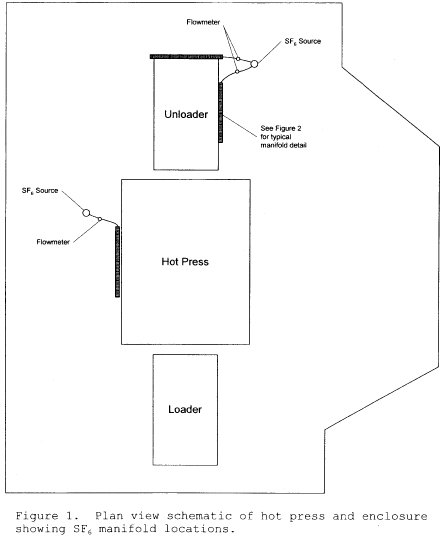
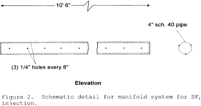 [69 FR 46011, July
30, 2004, as amended at 71 FR 8375, Feb. 16, 2006]
[69 FR 46011, July
30, 2004, as amended at 71 FR 8375, Feb. 16, 2006]Table 1 to Subpart EEEE of Part 63 - Organic Hazardous Air Pollutants
40:14.0.1.1.1.13.249.24.77 :
Table 1 to Subpart EEEE of Part 63 - Organic Hazardous Air PollutantsYou must use the organic HAP information listed in the following table to determine which of the liquids handled at your facility meet the HAP content criteria in the definition of Organic Liquid in § 63.2406.
| Compound name | CAS No. 1 |
|---|---|
| 2,4-D salts and esters | 94-75-7 |
| Acetaldehyde | 75-07-0 |
| Acetonitrile | 75-05-8 |
| Acetophenone | 98-86-2 |
| Acrolein | 107-02-8 |
| Acrylamide | 79-06-1 |
| Acrylic acid | 79-10-7 |
| Acrylonitrile | 107-13-1 |
| Allyl chloride | 107-05-1 |
| Aniline | 62-53-3 |
| Benzene | 71-43-2 |
| Biphenyl | 92-52-4 |
| Butadiene (1,3-) | 106-99-0 |
| Carbon tetrachloride | 56-23-5 |
| Chloroacetic acid | 79-11-8 |
| Chlorobenzene | 108-90-7 |
| 2-Chloro-1,3-butadiene (Chloroprene) | 126-99-8 |
| Chloroform | 67-66-3 |
| m-Cresol | 108-39-4 |
| o-Cresol | 95-48-7 |
| p-Cresol | 106-44-5 |
| Cresols/cresylic acid | 1319-77-3 |
| Cumene | 98-82-8 |
| Dibenzofurans | 132-64-9 |
| Dibutylphthalate | 84-74-2 |
| Dichloroethane (1,2-) (Ethylene dichloride) (EDC) | 107-06-2 |
| Dichloropropene (1,3-) | 542-75-6 |
| Diethanolamine | 111-42-2 |
| Diethyl aniline (N,N-) | 121-69-7 |
| Diethylene glycol monobutyl ether | 112-34-5 |
| Diethylene glycol monomethyl ether | 111-77-3 |
| Diethyl sulfate | 64-67-5 |
| Dimethyl formamide | 68-12-2 |
| Dimethylhydrazine (1,1-) | 57-14-7 |
| Dioxane (1,4-) (1,4-Diethyleneoxide) | 123-91-1 |
| Epichlorohydrin (1-Chloro-2,3-epoxypropane) | 106-89-8 |
| Epoxybutane (1,2-) | 106-88-7 |
| Ethyl acrylate | 140-88-5 |
| Ethylbenzene | 100-41-4 |
| Ethyl chloride (Chloroethane) | 75-00-3 |
| Ethylene dibromide (Dibromomethane) | 106-93-4 |
| Ethylene glycol | 107-21-1 |
| Ethylene glycol dimethyl ether | 110-71-4 |
| Ethylene glycol monomethyl ether | 109-86-4 |
| Ethylene glycol monomethyl ether acetate | 110-49-6 |
| Ethylene glycol monophenyl ether | 122-99-6 |
| Ethylene oxide | 75-21-8 |
| Ethylidene dichloride (1,1-Dichloroethane) | 75-34-3 |
| Formaldehyde | 50-00-0 |
| Hexachloroethane | 67-72-1 |
| Hexane | 110-54-3 |
| Hydroquinone | 123-31-9 |
| Isophorone | 78-59-1 |
| Maleic anhydride | 108-31-6 |
| Methanol | 67-56-1 |
| Methyl chloride (Chloromethane) | 74-87-3 |
| Methylene chloride (Dichloromethane) | 75-09-2 |
| Methylenedianiline (4,4′-) | 101-77-9 |
| Methylene diphenyl diisocyanate | 101-68-8 |
| Methyl hydrazine | 60-34-4 |
| Methyl isobutyl ketone (Hexone) (MIBK) | 108-10-1 |
| Methyl methacrylate | 80-62-6 |
| Methyl tert-butyl ether (MTBE) | 1634-04-4 |
| Naphthalene | 91-20-3 |
| Nitrobenzene | 98-95-3 |
| Phenol | 108-9-52 |
| Phthalic anhydride | 85-44-9 |
| Polycyclic organic matter | 50-32-8 |
| Propionaldehyde | 123-38-6 |
| Propylene dichloride (1,2-Dichloropropane) | 78-87-5 |
| Propylene oxide | 75-56-9 |
| Quinoline | 91-22-5 |
| Styrene | 100-42-5 |
| Styrene oxide | 96-09-3 |
| Tetrachloroethane (1,1,2,2-) | 79-34-5 |
| Tetrachloroethylene (Perchloroethylene) | 127-18-4 |
| Toluene | 108-88-3 |
| Toluene diisocyanate (2,4-) | 584-84-9 |
| o-Toluidine | 95-53-4 |
| Trichlorobenzene (1,2,4-) | 120-82-1 |
| Trichloroethane (1,1,1-) (Methyl chloroform) | 71-55-6 |
| Trichloroethane (1,1,2-) (Vinyl trichloride) | 79-00-5 |
| Trichloroethylene | 79-01-6 |
| Triethylamine | 121-44-8 |
| Trimethylpentane (2,2,4-) | 540-84-1 |
| Vinyl acetate | 108-05-4 |
| Vinyl chloride (Chloroethylene) | 75-01-4 |
| Vinylidene chloride (1,1-Dichloroethylene) | 75-35-4 |
| Xylene (m-) | 108-38-3 |
| Xylene (o-) | 95-47-6 |
| Xylene (p-) | 106-42-3 |
| Xylenes (isomers and mixtures) | 1330-20-7 |
1 CAS numbers refer to the Chemical Abstracts Services registry number assigned to specific compounds, isomers, or mixtures of compounds.
Table 2 to Subpart EEEE of Part 63 - Emission Limits
40:14.0.1.1.1.13.249.24.78 :
Table 2 to Subpart EEEE of Part 63 - Emission Limits| If you own or operate . . . | And if . . . | Then you must . . . 1 |
|---|---|---|
| 1. A storage tank at an existing affected source with a capacity ≥18.9 cubic meters (5,000 gallons) and <189.3 cubic meters (50,000 gallons) 2 | a. The stored organic liquid is not crude oil or condensate and if the annual average true vapor pressure of the total Table 1 organic HAP in the stored organic liquid is ≥27.6 kilopascals (4.0 psia) and <76.6 kilopascals (11.1 psia) | i. Reduce emissions of total organic HAP (or, upon approval, TOC) by at least 95 weight-percent or, as an option, to an exhaust concentration less than or equal to 20 ppmv, on a dry basis corrected to 3-percent oxygen for combustion devices using supplemental combustion air, by venting emissions through a closed vent system to any combination of control devices meeting the applicable requirements of subpart SS of this part and § 63.2346(l); OR |
| ii. Comply with the work practice standards specified in Table 4 to this subpart, items 1.a, 1.b, or 1.c for tanks storing liquids described in that table. | ||
| b. The stored organic liquid is crude oil or condensate | i. See the requirement in item 1.a.i or 1.a.ii of this table. | |
| 2. A storage tank at an existing affected source with a capacity ≥189.3 cubic meters (50,000 gallons) | a. The stored organic liquid is not crude oil or condensate and if the annual average true vapor pressure of the total Table 1 organic HAP in the stored organic liquid is <76.6 kilopascals (11.1 psia) | i. See the requirement in item 1.a.i or 1.a.ii of this table. |
| b. The stored organic liquid is crude oil or condensate | i. See the requirement in item 1.a.i or 1.a.ii of this table. | |
| 3. A storage tank at a reconstructed or new affected source with a capacity ≥18.9 cubic meters (5,000 gallons) and <37.9 cubic meters (10,000 gallons) | a. The stored organic liquid is not crude oil or condensate and if the annual average true vapor pressure of the total Table 1 organic HAP in the stored organic liquid is ≥27.6 kilopascals (4.0 psia) and <76.6 kilopascals (11.1 psia) | i. See the requirement in item 1.a.i or 1.a.ii of this table. |
| b. The stored organic liquid is crude oil or condensate | i. See the requirement in item 1.a.i or 1.a.ii of this table. | |
| 4. A storage tank at a reconstructed or new affected source with a capacity ≥37.9 cubic meters (10,000 gallons) and <189.3 cubic meters (50,000 gallons) | a. The stored organic liquid is not crude oil or condensate and if the annual average true vapor pressure of the total Table 1 organic HAP in the stored organic liquid is ≥0.7 kilopascals (0.1 psia) and <76.6 kilopascals (11.1 psia) | i. See the requirement in item 1.a.i or 1.a.ii of this table. |
| b. The stored organic liquid is crude oil or condensate | i. See the requirement in item 1.a.i or 1.a.ii of this table. | |
| 5. A storage tank at a reconstructed or new affected source with a capacity ≥189.3 cubic meters (50,000 gallons) | a. The stored organic liquid is not crude oil or condensate and if the annual average true vapor pressure of the total Table 1 organic HAP in the stored organic liquid is <76.6 kilopascals (11.1 psia) | i. See the requirement in item 1.a.i or 1.a.ii of this table. |
| b. The stored organic liquid is crude oil or condensate | i. See the requirement in item 1.a.i or 1.a.ii of this table. | |
| 6. A storage tank at an existing, reconstructed, or new affected source meeting the capacity criteria specified in Table 2 to this subpart, items 1 through 5 | a. The stored organic liquid is not crude oil or condensate and if the annual average true vapor pressure of the total Table 1 organic HAP in the stored organic liquid is ≥76.6 kilopascals (11.1 psia) | i. Reduce emissions of total organic HAP (or, upon approval, TOC) by at least 95 weight-percent or, as an option, to an exhaust concentration less than or equal to 20 ppmv, on a dry basis corrected to 3-percent oxygen for combustion devices using supplemental combustion air, by venting emissions through a closed vent system to any combination of control devices meeting the applicable requirements of subpart SS of this part and § 63.2346(l); OR |
| ii. Comply with the work practice standards specified in Table 4 to this subpart, item 2.a or 2.b, for tanks storing the liquids described in that table. | ||
| 7. A transfer rack at an existing facility where the total actual annual facility-level organic liquid loading volume through transfer racks is equal to or greater than 800,000 gallons and less than 10 million gallons | a. The total Table 1 organic HAP content of the organic liquid being loaded through one or more of the transfer rack's arms is at least 98 percent by weight and is being loaded into a transport vehicle | i. For all such loading arms at the rack, reduce emissions of total organic HAP (or, upon approval, TOC) from the loading of organic liquids either by venting the emissions that occur during loading through a closed vent system to any combination of control devices meeting the applicable requirements of subpart SS of this part and § 63.2346(l), achieving at least 98 weight-percent HAP reduction, OR, as an option, to an exhaust concentration less than or equal to 20 ppmv, on a dry basis corrected to 3-percent oxygen for combustion devices using supplemental combustion air; OR |
| ii. During the loading of organic liquids, comply with the work practice standards specified in item 3 of Table 4 to this subpart. | ||
| 8. A transfer rack at an existing facility where the total actual annual facility-level organic liquid loading volume through transfer racks is ≥10 million gallons | a. One or more of the transfer rack's arms is loading an organic liquid into a transport vehicle | i. See the requirements in items 7.a.i and 7.a.ii of this table. |
| 9. A transfer rack at a new facility where the total actual annual facility-level organic liquid loading volume through transfer racks is less than 800,000 gallons | a. The total Table 1 organic HAP content of the organic liquid being loaded through one or more of the transfer rack's arms is at least 25 percent by weight and is being loaded into a transport vehicle | i. See the requirements in items 7.a.i and 7.a.ii of this table. |
| b. One or more of the transfer rack's arms is filling a container with a capacity equal to or greater than 55 gallons | i. For all such loading arms
at the rack during the loading of organic liquids, comply with the
provisions of §§ 63.924 through 63.927; OR ii. During the loading of organic liquids, comply with the work practice standards specified in item 3.a of Table 4 to this subpart. |
|
| 10. A transfer rack at a new facility where the total actual annual facility-level organic liquid loading volume through transfer racks is equal to or greater than 800,000 gallons | a. One or more of the transfer rack's arms is loading an organic liquid into a transport vehicle | i. See the requirements in items 7.a.i and 7.a.ii of this table. |
| b. One or more of the transfer rack's arms is filling a container with a capacity equal to or greater than 55 gallons | i. For all such loading arms at the rack during the loading of organic liquids, comply with the provisions of §§ 63.924 through 63.927; OR | |
| ii. During the loading of organic liquids, comply with the work practice standards specified in item 3.a of Table 4 to this subpart. |
1 Beginning no later than the compliance dates specified in § 63.2342(e), for each storage tank and low throughput transfer rack, if you vent emissions through a closed vent system to a flare then you must comply with the requirements specified in § 63.2346(k).
2 Beginning no later than the compliance dates specified in § 63.2342(e), the tank capacity criteria, liquid vapor pressure criteria, and emission limits specified for storage tanks at an existing affected source in Table 2 to this subpart, item 1 no longer apply. Instead, you must comply with the requirements as specified in § 63.2346(a)(5) and Table 2b to this subpart.
Table 2b to Subpart EEEE of Part 63 - Emission Limits For Storage Tanks At Certain Existing Affected Sources
40:14.0.1.1.1.13.249.24.79 :
Table 2b to Subpart EEEE of Part 63 - Emission Limits For Storage Tanks At Certain Existing Affected SourcesAs stated in § 63.2346(a)(5), beginning no later than the compliance dates specified in § 63.2342(e), the requirements in this Table 2b to this subpart apply to storage tanks at an existing affected source in lieu of the requirements in Table 2 to this subpart, item 1 for storage tanks at an existing affected source.
| If you own or operate . . . | And if . . . | Then you must . . . |
|---|---|---|
| 1. A storage tank at an existing affected source with a capacity ≥18.9 cubic meters (5,000 gallons) and <75.7 cubic meters (20,000 gallons) | a. The stored organic liquid is not crude oil or condensate and if the annual average true vapor pressure of the total Table 1 organic HAP in the stored organic liquid is ≥27.6 kilopascals (4.0 psia) | i. Reduce emissions of total organic HAP (or, upon approval, TOC) by at least 95 weight-percent or, as an option, to an exhaust concentration less than or equal to 20 ppmv, on a dry basis corrected to 3- percent oxygen for combustion devices using supplemental combustion air, by venting emissions through a closed vent system to a flare meeting the requirements of §§ 63.983 and 63.2380, or by venting emissions through a closed vent system to any combination of nonflare control devices meeting the applicable requirements of subpart SS of this part and § 63.2346(l); OR. |
| ii. Comply with the work practice standards specified in Table 4 to this subpart, items 1.a, 1.b, or 1.c for tanks storing liquids described in that table. | ||
| b. The stored organic liquid is crude oil or condensate | i. See the requirement in item 1.a.i or ii of this table. | |
| 2. A storage tank at an existing affected source with a capacity ≥75.7 cubic meters (20,000 gallons) and <151.4 cubic meters (40,000 gallons) | a. The stored organic liquid is not crude oil or condensate and if the annual average true vapor pressure of the total Table 1 organic HAP in the stored organic liquid is ≥13.1 kilopascals (1.9 psia) | i. See the requirement in item 1.a.i or ii of this table. |
| b. The stored organic liquid is crude oil or condensate | i. See the requirement in item 1.a.i or ii of this table. | |
| 3. A storage tank at an existing affected source with a capacity ≥151.4 cubic meters (40,000 gallons) and <189.3 cubic meters (50,000 gallons) | a. The stored organic liquid is not crude oil or condensate and if the annual average true vapor pressure of the total Table 1 organic HAP in the stored organic liquid is ≥5.2 kilopascals (0.75 psia) | i. See the requirement in item 1.a.i or ii of this table. |
| b. The stored organic liquid is crude oil or condensate | i. See the requirement in item 1.a.i or ii of this table. |
Table 3 to Subpart EEEE of Part 63 - Operating Limits - High Throughput Transfer Racks
40:14.0.1.1.1.13.249.24.80 :
Table 3 to Subpart EEEE of Part 63 - Operating Limits - High Throughput Transfer RacksAs stated in § 63.2346(e), you must comply with the operating limits for existing, reconstructed, or new affected sources as follows:
| For each existing, each reconstructed, and each new affected source using . . . | You must . . . |
|---|---|
| 1. A thermal oxidizer to comply with an emission limit in Table 2 to this subpart | Maintain the daily average fire box or combustion zone temperature greater than or equal to the reference temperature established during the design evaluation or performance test that demonstrated compliance with the emission limit. |
| 2. A catalytic oxidizer to comply with an emission limit in Table 2 to this subpart | a. Replace the existing catalyst bed before the age of the bed exceeds the maximum allowable age established during the design evaluation or performance test that demonstrated compliance with the emission limit; AND |
| b. Maintain the daily average temperature at the inlet of the catalyst bed greater than or equal to the reference temperature established during the design evaluation or performance test that demonstrated compliance with the emission limit; AND | |
| c. Maintain the daily average temperature difference across the catalyst bed greater than or equal to the minimum temperature difference established during the design evaluation or performance test that demonstrated compliance with the emission limit. | |
| 3. An absorber to comply with an emission limit in Table 2 to this subpart | a. Maintain the daily average concentration level of organic compounds in the absorber exhaust less than or equal to the reference concentration established during the design evaluation or performance test that demonstrated compliance with the emission limit; OR |
| b. Maintain the daily average scrubbing liquid temperature less than or equal to the reference temperature established during the design evaluation or performance test that demonstrated compliance with the emission limit; AND | |
| Maintain the difference between the specific gravities of the saturated and fresh scrubbing fluids greater than or equal to the difference established during the design evaluation or performance test that demonstrated compliance with the emission limit. | |
| 4. A condenser to comply with an emission limit in Table 2 to this subpart | a. Maintain the daily average concentration level of organic compounds at the condenser exit less than or equal to the reference concentration established during the design evaluation or performance test that demonstrated compliance with the emission limit; OR |
| b. Maintain the daily average condenser exit temperature less than or equal to the reference temperature established during the design evaluation or performance test that demonstrated compliance with the emission limit. | |
| 5. An adsorption system with adsorbent regeneration to comply with an emission limit in Table 2 to this subpart | a. Maintain the daily average concentration level of organic compounds in the adsorber exhaust less than or equal to the reference concentration established during the design evaluation or performance test that demonstrated compliance with the emission limit; OR |
| b. Maintain the total regeneration stream mass flow during the adsorption bed regeneration cycle greater than or equal to the reference stream mass flow established during the design evaluation or performance test that demonstrated compliance with the emission limit; AND | |
| Before the adsorption cycle commences, achieve and maintain the temperature of the adsorption bed after regeneration less than or equal to the reference temperature established during the design evaluation or performance test that demonstrated compliance with the emission limit; AND | |
| Achieve a pressure reduction during each adsorption bed regeneration cycle greater than or equal to the pressure reduction established during the design evaluation or performance test that demonstrated compliance with the emission limit. | |
| 6. An adsorption system without adsorbent regeneration to comply with an emission limit in Table 2 to this subpart | a. Maintain the daily average concentration level of organic compounds in the adsorber exhaust less than or equal to the reference concentration established during the design evaluation or performance test that demonstrated compliance with the emission limit; OR |
| b. Replace the existing adsorbent in each segment of the bed with an adsorbent that meets the replacement specifications established during the design evaluation or performance test before the age of the adsorbent exceeds the maximum allowable age established during the design evaluation or performance test that demonstrated compliance with the emission limit; AND | |
| Maintain the temperature of the adsorption bed less than or equal to the reference temperature established during the design evaluation or performance test that demonstrated compliance with the emission limit. | |
| 7. A flare to comply with an emission limit in Table 2 to this subpart | a. Except as specified in item
7.d of this table, comply with the equipment and operating
requirements in § 63.987(a); AND b. Except as specified in item 7.d of this table, conduct an initial flare compliance assessment in accordance with § 63.987(b); AND |
| c. Except as specified in item 7.d of this table, install and operate monitoring equipment as specified in § 63.987(c). | |
| d. Beginning no later than the compliance dates specified in § 63.2342(e), comply with the requirements in § 63.2380 instead of the requirements in § 63.987 and the provisions regarding flare compliance assessments at § 63.997(a), (b), and (c). | |
| 8. Another type of control device to comply with an emission limit in Table 2 to this subpart | Submit a monitoring plan as specified in §§ 63.995(c) and 63.2366(b), and monitor the control device in accordance with that plan. |
Table 4 to Subpart EEEE of Part 63 - Work Practice Standards
40:14.0.1.1.1.13.249.24.81 :
Table 4 to Subpart EEEE of Part 63 - Work Practice StandardsAs stated in § 63.2346, you may elect to comply with one of the work practice standards for existing, reconstructed, or new affected sources in the following table. If you elect to do so, . . .
| For each . . . | You must . . . |
|---|---|
| 1. Storage tank at an existing, reconstructed, or new affected source meeting any set of tank capacity and organic HAP vapor pressure criteria specified in Table 2 to this subpart, items 1 through 5 or Table 2b to this subpart, items 1 through 3 | a. Comply with the requirements of 40 CFR part 63, subpart WW (control level 2), if you elect to meet 40 CFR part 63, subpart WW (control level 2) requirements as an alternative to the emission limit in Table 2 to this subpart, items 1 through 5 or the emission limit in Table 2b to this subpart, items 1 through 3; OR. |
| b. Comply with the requirements in §§ 63.2346(l) and 63.984 for routing emissions to a fuel gas system or back to a process; OR. | |
| c. Comply with the requirements of § 63.2346(a)(4) for vapor balancing emissions to the transport vehicle from which the storage tank is filled. | |
| 2. Storage tank at an existing, reconstructed, or new affected source meeting any set of tank capacity and organic HAP vapor pressure criteria specified in Table 2 to this subpart, item 6 | a. Comply with the
requirements in §§ 63.2346(l) and 63.984 for routing emissions to a
fuel gas system or back to a process; OR b. Comply with the requirements of § 63.2346(a)(4) for vapor balancing emissions to the transport vehicle from which the storage tank is filled. |
| 3. Transfer rack subject to control based on the criteria specified in Table 2 to this subpart, items 7 through 10, at an existing, reconstructed, or new affected source | a. If the option of a vapor balancing system is selected, install and, during the loading of organic liquids, operate a system that meets the requirements in Table 7 to this subpart, item 3.b.i and item 3.b.ii, as applicable; OR |
| b. Comply with the requirements in §§ 63.2346(l) and 63.984 during the loading of organic liquids, for routing emissions to a fuel gas system or back to a process. | |
| 4. Pump, valve, and sampling connection that operates in organic liquids service at least 300 hours per year at an existing, reconstructed, or new affected source | Comply with § 63.2346(l) and the requirements for pumps, valves, and sampling connections in 40 CFR part 63, subpart TT (control level 1), subpart UU (control level 2), or subpart H. |
| 5. Transport vehicles equipped with vapor collection equipment that are loaded at transfer racks that are subject to control based on the criteria specified in Table 2 to this subpart, items 7 through 10 | Follow the steps in 40 CFR 60.502(e) to ensure that organic liquids are loaded only into vapor-tight transport vehicles, and comply with the provisions in 40 CFR 60.502(f), (g), (h), and (i), except substitute the term transport vehicle at each occurrence of tank truck or gasoline tank truck in those paragraphs. |
| 6. Transport vehicles equipped without vapor collection equipment that are loaded at transfer racks that are subject to control based on the criteria specified in Table 2 to this subpart, items 7 through 10 | Ensure that organic liquids are loaded only into transport vehicles that have a current certification in accordance with the U.S. DOT qualification and maintenance requirements in 49 CFR part 180, subpart E for cargo tanks and subpart F for tank cars. |
Table 5 to Subpart EEEE of Part 63 - Requirements for Performance Tests and Design Evaluations
40:14.0.1.1.1.13.249.24.82 :
Table 5 to Subpart EEEE of Part 63 - Requirements for Performance Tests and Design EvaluationsAs stated in §§ 63.2354(a) and 63.2362, you must comply with the requirements for performance tests and design evaluations for existing, reconstructed, or new affected sources as follows:
| For . . . | You must conduct . . . | According to . . . | Using . . . | To determine . . . | According to the following requirements . . . |
|---|---|---|---|---|---|
| 1. Each existing, each reconstructed, and each new affected source using a nonflare control device to comply with an emission limit in Table 2 to this subpart, items 1 through 10, and each existing affected source using a nonflare control device to comply with an emission limit in Table 2b to this subpart, items 1 through 3 | a. A performance test to determine the organic HAP (or, upon a pproval, TOC) control efficiency of each nonflare control device, OR the exhaust concentration of each combustion device; OR | i. § 63.985(b)(1)(ii), § 63.988(b), § 63.990(b), or § 63.995(b) | (1) Method 1 or 1A in appendix A-1 of 40 CFR part 60, as appropriate | (A) Sampling port locations and the required number of traverse points | (i) Sampling sites must be
located at the inlet and outlet of each control device if complying
with the control efficiency requirement or at the outlet of the
control device if complying with the exhaust concentration
requirement; AND (ii) the outlet sampling site must be located at each control device prior to any releases to the atmosphere. |
| (2) Method 2, 2A, 2C, 2D, or 2F in appendix A-1 of 40 CFR part 60, or Method 2G in appendix A-2 of 40 CFR part 60, as appropriate | (A) Stack gas velocity and volumetric flow rate | See the requirements in items 1.a.i.(1)(A)(i) and (ii) of this table. | |||
| (3) Method 3A or 3B in appendix A-2 of 40 CFR part 60, as appropriate 1 | (A) Concentration of CO2 and O2 and dry molecular weight of the stack gas | See the requirements in items 1.a.i.(1)(A)(i) and (ii) of this table. | |||
| (4) Method 4 in appendix A-3 of 40 CFR part 60 | (A) Moisture content of the stack gas | See the requirements in items 1.a.i.(1)(A)(i) and (ii) of this table. | |||
| (5) Method 25 or 25A in appendix A-7 of 40 CFR part 60, as appropriate. Method 316, Method 320 4, or Method 323 in appendix A of this part if you must measure formaldehyde. You may not use Methods 320 2 4 or 323 for formaldehyde if the gas stream contains entrained water droplets | (A) TOC and formaldehyde emissions, from any control device | (i) The organic HAP used for
the calibration gas for Method 25A in appendix A-7 of 40 CFR part
60 must be the single organic HAP representing the largest percent
by volume of emissions; AND (ii) During the performance test, you must establish the operating parameter limits within which TOC emissions are reduced by the required weight-percent or, as an option for nonflare combustion devices, to 20-ppmv exhaust concentration. |
|||
| (6) Method 18 3 in appendix A-6 of 40 CFR part 60 or Method 320 2 4 of appendix A to this part, as appropriate. Method 316, Method 320 2 4, or Method 323 in appendix A of this part for measuring formaldehyde. You may not use Methods 320 or 323 if the gas stream contains entrained water droplets | (A) Total organic HAP and formaldehyde emissions, from non-combustion control devices | (i) During the performance test, you must establish the operating parameter limits within which total organic HAP emissions are reduced by the required weight-percent. | |||
| b. A design evaluation (for nonflare control devices) to determine the organic HAP (or, upon approval, TOC) control efficiency of each nonflare control device, or the exhaust concentration of each combustion control device | § 63.985(b)(1)(i) | During a design evaluation, you must establish the operating parameter limits within which total organic HAP, (or, upon approval, TOC) emissions are reduced by at least 95 weight-percent for storage tanks or 98 weight-percent for transfer racks, or, as an option for nonflare combustion devices, to 20-ppmv exhaust concentration. | |||
| 2. Each transport vehicle that you own that is equipped with vapor collection equipment and is loaded with organic liquids at a transfer rack that is subject to control based on the criteria specified in Table 2 to this subpart, items 7 through 10, at an existing, reconstructed, or new affected source | A performance test to determine the vapor tightness of the tank and then repair as needed until it passes the test | Method 27 of appendix A of 40 CFR part 60 | Vapor tightness | The pressure change in the tank must be no more than 250 pascals (1 inch of water) in 5 minutes after it is pressurized to 4,500 pascals (18 inches of water). |
1 The manual method in American Society of Mechanical Engineers (ASME) PTC 19.10-1981-Part 10 (2010) (incorporated by reference, see § 63.14) may be used instead of Method 3B in appendix A-2 of 40 CFR part 60 to determine oxygen concentration.
2 All compounds quantified by Method 320 of appendix A to this part must be validated according to Section 13.0 of Method 320.
3 ASTM D6420-18 (incorporated by reference, see § 63.14) may be used instead of Method 18 of 40 CFR part 60, appendix A-6 to determine total HAP emissions, but if you use ASTM D6420-18, you must use it under the conditions specified in § 63.2354(b)(3)(ii).
4 ASTM D6348-12e1 (incorporated by reference, see § 63.14) may be used instead of Method 320 of appendix A to this part under the following conditions: the test plan preparation and implementation in the Annexes to ASTM D6348-12e1, Sections A1 through A8 are mandatory; the percent (%) R must be determined for each target analyte (Equation A5.5); %R must be 70% ≥ R ≤ 130%; if the %R value does not meet this criterion for a target compound, then the test data is not acceptable for that compound and the test must be repeated for that analyte (i.e., the sampling and/or analytical procedure should be adjusted before a retest); and the %R value for each compound must be reported in the test report and all field measurements must be corrected with the calculated %R value for that compound by using the following equation: Reported Results = ((Measured Concentration in Stack))/(%R) × 100.
Table 6 to Subpart EEEE of Part 63 - Initial Compliance with Emission Limits
40:14.0.1.1.1.13.249.24.83 :
Table 6 to Subpart EEEE of Part 63 - Initial Compliance with Emission LimitsAs stated in §§ 63.2370(a) and 63.2382(b), you must show initial compliance with the emission limits for existing, reconstructed, or new affected sources as follows:
| For each . . . | For the following emission limit . . . | You have demonstrated initial
compliance if . . . |
|---|---|---|
| 1. Storage tank at an existing, reconstructed, or new affected source meeting any set of tank capacity and liquid organic HAP vapor pressure criteria specified in Table 2 to this subpart, items 1 through 6, or Table 2b to this subpart, items 1 through 3 | Reduce total organic HAP (or, upon approval, TOC) emissions by at least 95 weight-percent, or as an option for nonflare combustion devices to an exhaust concentration of ≤20 ppmv | Total organic HAP (or, upon approval, TOC) emissions, based on the results of the performance testing or design evaluation specified in Table 5 to this subpart, item 1.a or 1.b, respectively, are reduced by at least 95 weight-percent or as an option for nonflare combustion devices to an exhaust concentration ≤20 ppmv. |
| 2. Transfer rack that is subject to control based on the criteria specified in Table 2 to this subpart, items 7 through 10, at an existing, reconstructed, or new affected source | Reduce total organic HAP (or, upon approval, TOC) emissions from the loading of organic liquids by at least 98 weight-percent, or as an option for nonflare combustion devices to an exhaust concentration of ≤20 ppmv | Total organic HAP (or, upon approval, TOC) emissions from the loading of organic liquids, based on the results of the performance testing or design evaluation specified in Table 5 to this subpart, item 1.a or 1.b, respectively, are reduced by at least 98 weight-percent or as an option for nonflare combustion devices to an exhaust concentration of ≤20 ppmv. |
Table 7 to Subpart EEEE of Part 63 - Initial Compliance with Work Practice Standards
40:14.0.1.1.1.13.249.24.84 :
Table 7 to Subpart EEEE of Part 63 - Initial Compliance with Work Practice Standards| For each . . . | If you . . . | You have demonstrated initial
compliance if . . . |
|---|---|---|
| 1. Storage tank at an existing affected source meeting either set of tank capacity and liquid organic HAP vapor pressure criteria specified in Table 2 to this subpart, items 1 or 2, or Table 2b to this subpart, items 1 through 3 | a. Install a floating roof or equivalent control that meets the requirements in Table 4 to this subpart, item 1.a | i. After emptying and degassing, you visually inspect each internal floating roof before the refilling of the storage tank and perform seal gap inspections of the primary and secondary rim seals of each external floating roof within 90 days after the refilling of the storage tank. |
| b. Route emissions to a fuel gas system or back to a process | i. You meet the requirements in § 63.984(b) and submit the statement of connection required by § 63.984(c). | |
| c. Install and, during the filling of the storage tank with organic liquids, operate a vapor balancing system | i. You meet the requirements in § 63.2346(a)(4). | |
| 2. Storage tank at a reconstructed or new affected source meeting any set of tank capacity and liquid organic HAP vapor pressure criteria specified in Table 2 to this subpart, items 3 through 5 | a. Install a floating roof or equivalent control that meets the requirements in Table 4 to this subpart, item 1.a | i. You visually inspect each internal floating roof before the initial filling of the storage tank and perform seal gap inspections of the primary and secondary rim seals of each external floating roof within 90 days after the initial filling of the storage tank. |
| b. Route emissions to a fuel gas system or back to a process | i. See item 1.b.i of this table. | |
| c. Install and, during the filling of the storage tank with organic liquids, operate a vapor balancing system | i. See item 1.c.i of this table. | |
| 3. Transfer rack that is subject to control based on the criteria specified in Table 2 to this subpart, items 7 through 10, at an existing, reconstructed, or new affected source | a. Load organic liquids only into transport vehicles having current vapor tightness certification as described in Table 4 to this subpart, item 5 and item 6 | i. You comply with the provisions specified in Table 4 to this subpart, item 5 or item 6, as applicable. |
| b. Install and, during the loading of organic liquids, operate a vapor balancing system | i. You design and operate the
vapor balancing system to route organic HAP vapors displaced from
loading of organic liquids into transport vehicles to the storage
tank from which the liquid being loaded originated or to another
storage tank connected to a common header. ii. You design and operate the vapor balancing system to route organic HAP vapors displaced from loading of organic liquids into containers directly (e.g., no intervening tank or containment area such as a room) to the storage tank from which the liquid being loaded originated or to another storage tank connected to a common header. |
|
| c. Route emissions to a fuel gas system or back to a process | i. See item 1.b.i of this table. | |
| 4. Equipment leak component, as defined in § 63.2406, that operates in organic liquids service ≥300 hours per year at an existing, reconstructed, or new affected source | a. Carry out a leak detection and repair program or equivalent control according to one of the subparts listed in Table 4 to this subpart, item 4 | i. You specify which one of
the control programs listed in Table 4 to this subpart you have
selected, OR ii. Provide written specifications for your equivalent control approach. |
Table 8 to Subpart EEEE of Part 63 - Continuous Compliance with Emission Limits
40:14.0.1.1.1.13.249.24.85 :
Table 8 to Subpart EEEE of Part 63 - Continuous Compliance with Emission LimitsAs stated in §§ 63.2378(a) and (b) and 63.2390(b), you must show continuous compliance with the emission limits for existing, reconstructed, or new affected sources according to the following table:
| For each . . . | For the following emission limit . . . | You must demonstrate continuous compliance by . . . |
|---|---|---|
| 1. Storage tank at an existing, reconstructed, or new affected source meeting any set of tank capacity and liquid organic HAP vapor pressure criteria specified in Table 2 to this subpart, items 1 through 6 or Table 2b to this subpart, items 1 through 3 | a. Reduce total organic HAP (or, upon approval, TOC) emissions from the closed vent system and control device by 95 weight-percent or greater, or as an option to 20 ppmv or less of total organic HAP (or, upon approval, TOC) in the exhaust of combustion devices | i. Performing CMS monitoring
and collecting data according to §§ 63.2366, 63.2374, and 63.2378,
except as specified in item 1.a.iii of this table; AND ii. Maintaining the operating limits established during the design evaluation or performance test that demonstrated compliance with the emission limit. iii. Beginning no later than the compliance dates specified in § 63.2342(e), if you use a flare, you must demonstrate continuous compliance by performing CMS monitoring and collecting data according to requirements in § 63.2380. |
| 2. Transfer rack that is subject to control based on the criteria specified in Table 2 to this subpart, items 7 through 10, at an existing, reconstructed, or new affected source | a. Reduce total organic HAP (or, upon approval, TOC) emissions during the loading of organic liquids from the closed vent system and control device by 98 weight-percent or greater, or as an option to 20 ppmv or less of total organic HAP (or, upon approval, TOC) in the exhaust of combustion devices | i. Performing CMS monitoring
and collecting data according to §§ 63.2366, 63.2374, and 63.2378
during the loading of organic liquids, except as specified in item
2.a.iii of this table; AND ii. Maintaining the operating limits established during the design evaluation or performance test that demonstrated compliance with the emission limit during the loading of organic liquids. iii. Beginning no later than the compliance dates specified in § 63.2342(e), if you use a flare, you must demonstrate continuous compliance by performing CMS monitoring and collecting data according to requirements in § 63.2380. |
Table 9 to Subpart EEEE of Part 63 - Continuous Compliance with Operating Limits - High Throughput Transfer Racks
40:14.0.1.1.1.13.249.24.86 :
Table 9 to Subpart EEEE of Part 63 - Continuous Compliance with Operating Limits - High Throughput Transfer RacksAs stated in §§ 63.2378(a) and (b) and 63.2390(b), you must show continuous compliance with the operating limits for existing, reconstructed, or new affected sources according to the following table:
| For each existing, reconstructed, and each new affected source using . . . | For the following operating limit . . . | You must demonstrate continuous compliance by . . . |
|---|---|---|
| 1. A thermal oxidizer to comply with an emission limit in Table 2 to this subpart | a. Maintain the daily average fire box or combustion zone, as applicable, temperature greater than or equal to the reference temperature established during the design evaluation or performance test that demonstrated compliance with the emission limit | i. Continuously monitoring and
recording fire box or combustion zone, as applicable, temperature
every 15 minutes and maintaining the daily average fire box
temperature greater than or equal to the reference temperature
established during the design evaluation or performance test that
demonstrated compliance with the emission limit; AND ii. Keeping the applicable records required in § 63.998. 1 |
| 2. A catalytic oxidizer to comply with an emission limit in Table 2 to this subpart | a. Replace the existing catalyst bed before the age of the bed exceeds the maximum allowable age established during the design evaluation or performance test that demonstrated compliance with the emission limit; AND | i. Replacing the existing
catalyst bed before the age of the bed exceeds the maximum
allowable age established during the design evaluation or
performance test that demonstrated compliance with the emission
limit; AND ii. Keeping the applicable records required in § 63.998. 1 |
| b. Maintain the daily average temperature at the inlet of the catalyst bed greater than or equal to the reference temperature established during the design evaluation or performance test that demonstrated compliance with the emission limit; AND | i. Continuously monitoring and
recording the temperature at the inlet of the catalyst bed at least
every 15 minutes and maintaining the daily average temperature at
the inlet of the catalyst bed greater than or equal to the
reference temperature established during the design evaluation or
performance test that demonstrated compliance with the emission
limit; AND ii. Keeping the applicable records required in § 63.998. 1 |
|
| c. Maintain the daily average temperature difference across the catalyst bed greater than or equal to the minimum temperature difference established during the design evaluation or performance test that demonstrated compliance with the emission limit | i. Continuously monitoring and
recording the temperature at the outlet of the catalyst bed every
15 minutes and maintaining the daily average temperature difference
across the catalyst bed greater than or equal to the minimum
temperature difference established during the design evaluation or
performance test that demonstrated compliance with the emission
limit; AND ii. Keeping the applicable records required in § 63.998. 1 |
|
| 3. An absorber to comply with an emission limit in Table 2 to this subpart | a. Maintain the daily average concentration level of organic compounds in the absorber exhaust less than or equal to the reference concentration established during the design evaluation or performance test that demonstrated compliance with the emission limit; OR | i. Continuously monitoring the
organic concentration in the absorber exhaust and maintaining the
daily average concentration less than or equal to the reference
concentration established during the design evaluation or
performance test that demonstrated compliance with the emission
limit; AND ii. Keeping the applicable records required in § 63.998. 1 |
| b. Maintain the daily average
scrubbing liquid temperature less than or equal to the reference
temperature established during the design evaluation or performance
test that demonstrated compliance with the emission limit; AND Maintain the difference between the specific gravities of the saturated and fresh scrubbing fluids greater than or equal to the difference established during the design evaluation or performance test that demonstrated compliance with the emission limit |
i. Continuously monitoring the
scrubbing liquid temperature and maintaining the daily average
temperature less than or equal to the reference temperature
established during the design evaluation or performance test that
demonstrated compliance with the emission limit; AND ii. Maintaining the difference between the specific gravities greater than or equal to the difference established during the design evaluation or performance test that demonstrated compliance with the emission limit; AND iii. Keeping the applicable records required in § 63.998. 1 |
|
| 4. A condenser to comply with an emission limit in Table 2 to this subpart | a. Maintain the daily average concentration level of organic compounds at the exit of the condenser less than or equal to the reference concentration established during the design evaluation or performance test that demonstrated compliance with the emission limit; OR | i. Continuously monitoring the
organic concentration at the condenser exit and maintaining the
daily average concentration less than or equal to the reference
concentration established during the design evaluation or
performance test that demonstrated compliance with the emission
limit; AND ii. Keeping the applicable records required in § 63.998. 1 |
| b. Maintain the daily average condenser exit temperature less than or equal to the reference temperature established during the design evaluation or performance test that demonstrated compliance with the emission limit | i. Continuously monitoring and
recording the temperature at the exit of the condenser at least
every 15 minutes and maintaining the daily average temperature less
than or equal to the reference temperature established during the
design evaluation or performance test that demonstrated compliance
with the emission limit; AND ii. Keeping the applicable records required in § 63.998. 1 |
|
| 5. An adsorption system with adsorbent regeneration to comply with an emission limit in Table 2 to this subpart | a. Maintain the daily average concentration level of organic compounds in the adsorber exhaust less than or equal to the reference concentration established during the design evaluation or performance test that demonstrated compliance with the emission limit; OR | i. Continuously monitoring the
daily average organic concentration in the adsorber exhaust and
maintaining the concentration less than or equal to the reference
concentration established during the design evaluation or
performance test that demonstrated compliance with the emission
limit; AND ii. Keeping the applicable records required in § 63.998. 1 |
| b. Maintain the total
regeneration stream mass flow during the adsorption bed
regeneration cycle greater than or equal to the reference stream
mass flow established during the design evaluation or performance
test that demonstrated compliance with the emission limit; AND Before the adsorption cycle commences, achieve and maintain the temperature of the adsorption bed after regeneration less than or equal to the reference temperature established during the design evaluation or performance test; AND Achieve greater than or equal to the pressure reduction during the adsorption bed regeneration cycle established during the design evaluation or performance test that demonstrated compliance with the emission limit |
i. Maintaining the total
regeneration stream mass flow during the adsorption bed
regeneration cycle greater than or equal to the reference stream
mass flow established during the design evaluation or performance
test that demonstrated compliance with the emission limit; AND ii. Maintaining the temperature of the adsorption bed after regeneration less than or equal to the reference temperature established during the design evaluation or performance test that demonstrated compliance with the emission limit; AND iii. Achieving greater than or equal to the pressure reduction during the regeneration cycle established during the design evaluation or performance test that demonstrated compliance with the emission limit; AND iv. Keeping the applicable records required in § 63.998. 1 |
|
| 6. An adsorption system without adsorbent regeneration to comply with an emission limit in Table 2 to this subpart | a. Maintain the daily average concentration level of organic compounds in the adsorber exhaust less than or equal to the reference concentration established during the design evaluation or performance test that demonstrated compliance with the emission limit; OR | i. Continuously monitoring the
organic concentration in the adsorber exhaust and maintaining the
concentration less than or equal to the reference concentration
established during the design evaluation or performance test that
demonstrated compliance with the emission limit; AND ii. Keeping the applicable records required in § 63.998. 1 |
| b. Replace the existing
adsorbent in each segment of the bed before the age of the
adsorbent exceeds the maximum allowable age established during the
design evaluation or performance test that demonstrated compliance
with the emission limit; AND Maintain the temperature of the adsorption bed less than or equal to the reference temperature established during the design evaluation or performance test that demonstrated compliance with the emission limit |
i. Replacing the existing
adsorbent in each segment of the bed with an adsorbent that meets
the replacement specifications established during the design
evaluation or performance test before the age of the adsorbent
exceeds the maximum allowable age established during the design
evaluation or performance test that demonstrated compliance with
the emission limit; AND ii. Maintaining the temperature of the adsorption bed less than or equal to the reference temperature established during the design evaluation or performance test that demonstrated compliance with the emission limit; AND iii. Keeping the applicable records required in § 63.998. 1 |
|
| 7. A flare to comply with an emission limit in Table 2 to this subpart | a. Except as specified in item 7.e of this table, maintain a pilot flame or flare flame in the flare at all times that vapors may be vented to the flare (§ 63.11(b)(5)); AND | i. Continuously operating a
device that detects the presence of the pilot flame or flare flame;
AND ii. Keeping the applicable records required in § 63.998. 1 |
| b. Except as specified in item 7.e of this table, maintain a flare flame at all times that vapors are being vented to the flare (§ 63.11(b)(5)); AND | i. Maintaining a flare flame
at all times that vapors are being vented to the flare; AND ii. Keeping the applicable records required in § 63.998. 1 |
|
| c. Except as specified in item 7.e of this table, operate the flare with no visible emissions, except for up to 5 minutes in any 2 consecutive hours (§ 63.11(b)(4)); AND EITHER | i. Operating the flare with no
visible emissions exceeding the amount allowed; AND ii. Keeping the applicable records required in § 63.998. 1 |
|
| d.1. Except as specified in item 7.e of this table, operate the flare with an exit velocity that is within the applicable limits in § 63.11(b)(7) and (8) and with a net heating value of the gas being combusted greater than the applicable minimum value in § 63.11(b)(6)(ii); OR | i. Operating the flare within
the applicable exit velocity limits; AND ii. Operating the flare with the gas heating value greater than the applicable minimum value; AND iii. Keeping the applicable records required in § 63.998. 1 |
|
| d.2. Except as specified in item 7.e of this table, adhere to the requirements in § 63.11(b)(6)(i) | i. Operating the flare within
the applicable limits in 63.11(b)(6)(i); AND ii. Keeping the applicable records required in § 63.998. 1 |
|
| e. Beginning no later than the compliance dates specified in § 63.2342(e), comply with the requirements in § 63.2380 instead of the requirements in § 63.11(b) | i. Operating the flare with
the applicable limits in § 63.2380; AND ii. Keeping the applicable records required in § 63.2390(h). |
|
| 8. Another type of control device to comply with an emission limit in Table 2 to this subpart | Submit a monitoring plan as specified in §§ 63.995(c) and 63.2366(b) and monitor the control device in accordance with that plan | Submitting a monitoring plan and monitoring the control device according to that plan. |
1 Beginning no later than the compliance dates specified in § 63.2342(e), the referenced provisions specified in § 63.2346(l) do not apply.
Table 10 to Subpart EEEE of Part 63 - Continuous Compliance with Work Practice Standards
40:14.0.1.1.1.13.249.24.87 :
Table 10 to Subpart EEEE of Part 63 - Continuous Compliance with Work Practice StandardsAs stated in §§ 63.2378(a) and (b) and 63.2386(c)(6), you must show continuous compliance with the work practice standards for existing, reconstructed, or new affected sources according to the following table:
| For each . . . | For the following standard . . . | You must demonstrate continuous compliance by . . . |
|---|---|---|
| 1. Internal floating roof (IFR) storage tank at an existing, reconstructed, or new affected source meeting any set of tank capacity, and vapor pressure criteria specified in Table 2 to this subpart, items 1 through 5, or Table 2b to this subpart, items 1 through 3 | a. Install a floating roof designed and operated according to the applicable specifications in § 63.1063(a) and (b) | i. Visually inspecting the
floating roof deck, deck fittings, and rim seals of each IFR once
per year (§ 63.1063(d)(2)); AND ii. Visually inspecting the floating roof deck, deck fittings, and rim seals of each IFR either each time the storage tank is completely emptied and degassed or every 10 years, whichever occurs first (§ 63.1063(c)(1), (d)(1), and (e)); AND iii. Keeping the tank records required in § 63.1065. |
| 2. External floating roof (EFR) storage tank at an existing, reconstructed, or new affected source meeting any set of tank capacity and vapor pressure criteria specified in Table 2 to this subpart, items 1 through 5, or Table 2b to this subpart, items 1 through 3 | a. Install a floating roof designed and operated according to the applicable specifications in § 63.1063(a) and (b) | i. Visually inspecting the
floating roof deck, deck fittings, and rim seals of each EFR either
each time the storage tank is completely emptied and degassed or
every 10 years, whichever occurs first (§ 63.1063(c)(2), (d), and
(e)); AND ii. Performing seal gap measurements on the secondary seal of each EFR at least once every year, and on the primary seal of each EFR at least every 5 years (§ 63.1063(c)(2), (d), and (e)); AND iii. Keeping the tank records required in § 63.1065. |
| 3. IFR or EFR tank at an existing, reconstructed, or new affected source meeting any set of tank capacity and vapor pressure criteria specified in Table 2 to this subpart, items 1 through 5, or Table 2b to this subpart, items 1 through 3 | a. Repair the conditions causing storage tank inspection failures (§ 63.1063(e)) | i. Repairing conditions
causing inspection failures: Before refilling the storage tank with
organic liquid, or within 45 days (or up to 105 days with
extensions) for a tank containing organic liquid; AND ii. Keeping the tank records required in § 63.1065(b). |
| 4. Transfer rack that is subject to control based on the criteria specified in Table 2 to this subpart, items 7 through 10, at an existing, reconstructed, or new affected source | a. Ensure that organic liquids are loaded into transport vehicles in accordance with the requirements in Table 4 to this subpart, items 5 or 6, as applicable | i. Ensuring that organic liquids are loaded into transport vehicles in accordance with the requirements in Table 4 to this subpart, items 5 or 6, as applicable. |
| b. Install and, during the loading of organic liquids, operate a vapor balancing system | i. Monitoring each potential source of vapor leakage in the system quarterly during the loading of a transport vehicle or the filling of a container using the methods and procedures described in the rule requirements selected for the work practice standard for equipment leak components as specified in Table 4 to this subpart, item 4. An instrument reading of 500 ppmv defines a leak. Repair of leaks is performed according to the repair requirements specified in your selected equipment leak standards | |
| c. Route emissions to a fuel gas system or back to a process | i. Continuing to meet the requirements specified in § 63.984(b) | |
| 5. Equipment leak component, as defined in § 63.2406, that operates in organic liquids service at least 300 hours per year | a. Comply with § 63.2346(l) and the requirements of 40 CFR part 63, subpart TT, UU, or H | i. Carrying out a leak detection and repair program in accordance with the subpart selected from the list in item 5.a of this table |
| 6. Storage tank at an existing, reconstructed, or new affected source meeting any of the tank capacity and vapor pressure criteria specified in Table 2 to this subpart, items 1 through 6, or Table 2b to this subpart, items 1 through 3 | a. Route emissions to a fuel gas system or back to the process | i. Continuing to meet the requirements specified in § 63.984(b) |
| b. Install and, during the filling of the storage tank with organic liquids, operate a vapor balancing system | i. Except for pressure relief devices, monitoring each potential source of vapor leakage in the system, including, but not limited to pumps, valves, and sampling connections, quarterly during the loading of a storage tank using the methods and procedures described in the rule requirements selected for the work practice standard for equipment leak components as specified in Table 4 to this subpart, item 4. An instrument reading of 500 ppmv defines a leak. Repair of leaks is performed according to the repair requirements specified in your selected equipment leak standards. For pressure relief devices, comply with § 63.2346(a)(4)(v). If no loading of a storage tank occurs during a quarter, then monitoring of the vapor balancing system is not required |
Table 11 to Subpart EEEE of Part 63 - Requirements for Reports
40:14.0.1.1.1.13.249.24.88 :
Table 11 to Subpart EEEE of Part 63 - Requirements for ReportsAs stated in § 63.2386(a), (b), and (f), you must submit compliance reports and startup, shutdown, and malfunction reports according to the following table:
| You must submit a(n) . . . | The report must contain . . . | You must submit the report . . . |
|---|---|---|
| 1. Compliance report or Periodic Report | a. The information specified in § 63.2386(c), (d), (e). If you had a SSM during the reporting period and you took actions consistent with your SSM plan, the report must also include the information in § 63.10(d)(5)(i) except as specified in item 1.e of this table; AND | Semiannually, and it must be postmarked or electronically submitted by January 31 or July 31, in accordance with § 63.2386(b). |
| b. The information required by 40 CFR part 63, subpart TT, UU, or H, as applicable, for pumps, valves, and sampling connections; AND | See the submission requirement in item 1.a of this table. | |
| c. The information required by § 63.999(c); AND | See the submission requirement in item 1.a of this table. | |
| d. The information specified in § 63.1066(b) including: Notification of inspection, inspection results, requests for alternate devices, and requests for extensions, as applicable | See the submission requirement in item 1.a of this table. | |
| e. Beginning no later than the compliance dates specified in § 63.2342(e), the requirement to include the information in § 63.10(d)(5)(i) no longer applies. | ||
| 2. Immediate SSM report if you had a SSM that resulted in an applicable emission standard in the relevant standard being exceeded, and you took an action that was not consistent with your SSM plan | a. The information required in § 63.10(d)(5)(ii) | i. Except as specified in item
2.a.ii of this table, by letter within 7 working days after the end
of the event unless you have made alternative arrangements with the
permitting authority (§ 63.10(d)(5)(ii)). ii. Beginning no later than the compliance dates specified in § 63.2342(e), item 2.a.i of this table no longer applies. |
Table 12 to Subpart EEEE of Part 63 - Applicability of General Provisions to Subpart EEEE
40:14.0.1.1.1.13.249.24.89 :
Table 12 to Subpart EEEE of Part 63 - Applicability of General Provisions to Subpart EEEEAs stated in §§ 63.2382 and 63.2398, you must comply with the applicable General Provisions requirements as follows:
| Citation | Subject | Brief description | Applies to subpart EEEE |
|---|---|---|---|
| § 63.1 | Applicability | Initial applicability determination; Applicability after standard established; Permit requirements; Extensions, Notifications | Yes. |
| § 63.2 | Definitions | Definitions for part 63 standards | Yes. |
| § 63.3 | Units and Abbreviations | Units and abbreviations for part 63 standards | Yes. |
| § 63.4 | Prohibited Activities and Circumvention | Prohibited activities; Circumvention, Severability | Yes. |
| § 63.5 | Construction/Reconstruction | Applicability; Applications; Approvals | Yes. |
| § 63.6(a) | Compliance with Standards/O&M Applicability | GP apply unless compliance extension; GP apply to area sources that become major | Yes. |
| § 63.6(b)(1)-(4) | Compliance Dates for New and Reconstructed Sources | Standards apply at effective date; 3 years after effective date; upon startup; 10 years after construction or reconstruction commences for CAA section 112(f) | Yes. |
| § 63.6(b)(5) | Notification | Must notify if commenced construction or reconstruction after proposal | Yes. |
| § 63.6(b)(6) | [Reserved] | ||
| § 63.6(b)(7) | Compliance Dates for New and Reconstructed Area Sources That Become Major | Area sources that become major must comply with major source standards immediately upon becoming major, regardless of whether required to comply when they were an area source | Yes. |
| § 63.6(c)(1)-(2) | Compliance Dates for Existing Sources | Comply according to date in this subpart, which must be no later than 3 years after effective date; for section 112(f) standards, comply within 90 days of effective date unless compliance extension | Yes. |
| § 63.6(c)(3)-(4) | [Reserved] | ||
| § 63.6(c)(5) | Compliance Dates for Existing Area Sources That Become Major | Area sources that become major must comply with major source standards by date indicated in this subpart or by equivalent time period (e.g., 3 years) | Yes. |
| § 63.6(d) | [Reserved] | ||
| § 63.6(e)(1)(i) | Operation and Maintenance | Operate to minimize emissions at all times | Yes, before July 7, 2023. No, beginning on and after July 7, 2023. See § 63.2350(d) for general duty requirement. |
| § 63.6(e)(1)(ii) | Operation and Maintenance | Correct malfunctions as soon as practicable | Yes, before July 7, 2023. No, beginning on and after July 7, 2023. |
| § 63.6(e)(1)(iii) | Operation and Maintenance | Operation and maintenance requirements independently enforceable; information Administrator will use to determine if operation and maintenance requirements were met | Yes. |
| § 63.6(e)(2) | [Reserved] | ||
| § 63.6(e)(3) | SSM Plan | Requirement for SSM plan; content of SSM plan; actions during SSM | Yes, before July 7, 2023;
however, (1) the 2-day reporting requirement in paragraph §
63.6(e)(3)(iv) does not apply and (2) § 63.6(e)(3) does not apply
to emissions sources not requiring control. No, beginning on and after July 7, 2023. |
| § 63.6(f)(1) | Compliance Except During SSM | You must comply with emission standards at all times except during SSM | Yes, before July 7, 2023. No, beginning on and after July 7, 2023. |
| § 63.6(f)(2)-(3) | Methods for Determining Compliance | Compliance based on performance test, operation and maintenance plans, records, inspection | Yes. |
| § 63.6(g)(1)-(3) | Alternative Standard | Procedures for getting an alternative standard | Yes. |
| § 63.6(h)(1) | Opacity/Visible Emission Standards | You must comply with opacity and visible emission standards at all times except during SSM | Yes, before July 7, 2023. No, beginning on and after July 7, 2023. |
| § 63.6(h)(2)-(9) | Opacity/Visible Emission Standards | Requirements for compliance with opacity and visible emission standards | No; except as it applies to flares for which Method 22 observations are required as part of a flare compliance assessment. |
| § 63.6(i)(1)-(14) | Compliance Extension | Procedures and criteria for Administrator to grant compliance extension | Yes. |
| § 63.6(j) | Presidential Compliance Exemption | President may exempt any source from requirement to comply with this subpart | Yes. |
| § 63.7(a)(2) | Performance Test Dates | Dates for conducting initial performance testing; must conduct 180 days after compliance date | Yes. |
| § 63.7(a)(3) | Section 114 Authority | Administrator may require a performance test under CAA section 114 at any time | Yes. |
| § 63.7(b)(1) | Notification of Performance Test | Must notify Administrator 60 days before the test | Yes. |
| § 63.7(b)(2) | Notification of Rescheduling | If you have to reschedule performance test, must notify Administrator of rescheduled date as soon as practicable and without delay | Yes. |
| § 63.7(c) | Quality Assurance (QA)/Test Plan | Requirement to submit site-specific test plan 60 days before the test or on date Administrator agrees with; test plan approval procedures; performance audit requirements; internal and external QA procedures for testing | Yes. |
| § 63.7(d) | Testing Facilities | Requirements for testing facilities | Yes. |
| § 63.7(e)(1) | Conditions for Conducting Performance Tests | Performance tests must be conducted under representative conditions; cannot conduct performance tests during SSM | Yes, before July 7, 2023. No, beginning on and after July 7, 2023. See § 63.2354(b)(6). |
| § 63.7(e)(2) | Conditions for Conducting Performance Tests | Must conduct according to this subpart and EPA test methods unless Administrator approves alternative | Yes. |
| § 63.7(e)(3) | Test Run Duration | Must have three test runs of at least 1 hour each; compliance is based on arithmetic mean of three runs; conditions when data from an additional test run can be used | Yes; however, for transfer racks per §§ 63.987(b)(3)(i)(A)-(B) and 63.997(e)(1)(v)(A)-(B) provide exceptions to the requirement for test runs to be at least 1 hour each. |
| § 63.7(e)(4) | Authority to Require Testing | Administrator has authority to require testing under CAA section 114 regardless of § 63.7 (e)(1)-(3) | Yes. |
| § 63.7(f) | Alternative Test Method | Procedures by which Administrator can grant approval to use an intermediate or major change, or alternative to a test method | Yes. |
| § 63.7(g) | Performance Test Data Analysis | Must include raw data in performance test report; must submit performance test data 60 days after end of test with the Notification of Compliance Status; keep data for 5 years | Yes, except this subpart specifies how and when the performance test and performance evaluation results are reported. |
| § 63.7(h) | Waiver of Tests | Procedures for Administrator to waive performance test | Yes. |
| § 63.8(a)(1) | Applicability of Monitoring Requirements | Subject to all monitoring requirements in standard | Yes. |
| § 63.8(a)(2) | Performance Specifications | Performance Specifications in appendix B of 40 CFR part 60 apply | Yes. |
| § 63.8(a)(3) | [Reserved] | ||
| § 63.8(a)(4) | Monitoring of Flares | Monitoring requirements for flares in § 63.11 | Yes, before July 7, 2023;
however, flare monitoring requirements in § 63.987(c) also apply
before July 7, 2023. No, beginning on and after July 7, 2023. See § 63.2380. |
| § 63.8(b)(1) | Monitoring | Must conduct monitoring according to standard unless Administrator approves alternative | Yes. |
| § 63.8(b)(2)-(3) | Multiple Effluents and Multiple Monitoring Systems | Specific requirements for installing monitoring systems; must install on each affected source or after combined with another affected source before it is released to the atmosphere provided the monitoring is sufficient to demonstrate compliance with the standard; if more than one monitoring system on an emission point, must report all monitoring system results, unless one monitoring system is a backup | Yes. |
| § 63.8(c)(1) | Monitoring System Operation and Maintenance | Maintain monitoring system in a manner consistent with good air pollution control practices | Yes. |
| § 63.8(c)(1)(i) | Routine and Predictable SSM | Keep parts for routine repairs readily available; reporting requirements for SSM when action is described in SSM plan | Yes, before July 7, 2023. No, beginning on and after July 7, 2023. |
| § 63.8(c)(1)(ii) | CMS malfunction not in SSM plan | Keep the necessary parts for routine repairs if CMS malfunctions | Yes. |
| § 63.8(c)(1)(iii) | Compliance with Operation and Maintenance Requirements | Develop a written SSM plan for CMS | Yes, before July 7, 2023. No, beginning on and after July 7, 2023. |
| § 63.8(c)(2)-(3) | Monitoring System Installation | Must install to get representative emission or parameter measurements; must verify operational status before or at performance test | Yes. |
| § 63.8(c)(4) | CMS Requirements | CMS must be operating except during breakdown, out-of-control, repair, maintenance, and high-level calibration drifts; COMS must have a minimum of one cycle of sampling and analysis for each successive 10-second period and one cycle of data recording for each successive 6-minute period; CEMS must have a minimum of one cycle of operation for each successive 15-minute period | Yes; however, COMS are not applicable. |
| § 63.8(c)(5) | COMS Minimum Procedures | COMS minimum procedures | No. |
| § 63.8(c)(6)-(8) | CMS Requirements | Zero and high level calibration check requirements. Out-of-control periods | Yes, but only applies for CEMS. Subpart SS of this part provides requirements for CPMS. |
| § 63.8(d)(1)-(2) | CMS Quality Control | Requirements for CMS quality control | Yes, but only applies for CEMS. Subpart SS of this part provides requirements for CPMS. |
| § 63.8(d)(3) | CMS Quality Control | Must keep quality control plan on record for 5 years; keep old versions | Yes, before July 7, 2023, but
only applies for CEMS. Subpart SS of this part provides
requirements for CPMS. No, beginning on and after July 7, 2023. See § 63.2366(c). |
| § 63.8(e) | CMS Performance Evaluation | Notification, performance evaluation test plan, reports | Yes, but only applies for CEMS, except this subpart specifies how and when the performance evaluation results are reported. |
| § 63.8(f)(1)-(5) | Alternative Monitoring Method | Procedures for Administrator to approve alternative monitoring | Yes, but subpart SS of this part also provides procedures for approval of CPMS. |
| § 63.8(f)(6) | Alternative to Relative Accuracy Test | Procedures for Administrator to approve alternative relative accuracy tests for CEMS | Yes. |
| § 63.8(g) | Data Reduction | COMS 6-minute averages calculated over at least 36 evenly spaced data points; CEMS 1 hour averages computed over at least four equally spaced data points; data that cannot be used in average | Yes; however, COMS are not applicable. |
| § 63.9(a) | Notification Requirements | Applicability and State delegation | Yes. |
| § 63.9(b)(1)-(2), (4)-(5) | Initial Notifications | Submit notification within 120 days after effective date; notification of intent to construct/reconstruct, notification of commencement of construction/reconstruction, notification of startup; contents of each | Yes. |
| § 63.9(c) | Request for Compliance Extension | Can request if cannot comply by date or if installed best available control technology or lowest achievable emission rate (BACT/LAER) | Yes. |
| § 63.9(d) | Notification of Special Compliance Requirements for New Sources | For sources that commence construction between proposal and promulgation and want to comply 3 years after effective date | Yes. |
| § 63.9(e) | Notification of Performance Test | Notify Administrator 60 days prior | Yes. |
| § 63.9(f) | Notification of VE/Opacity Test | Notify Administrator 30 days prior | No. |
| § 63.9(g) | Additional Notifications When Using CMS | Notification of performance evaluation; notification about use of COMS data; notification that exceeded criterion for relative accuracy alternative | Yes; however, there are no opacity standards. |
| § 63.9(h)(1)-(6) | Notification of Compliance Status | Contents due 60 days after end of performance test or other compliance demonstration, except for opacity/visible emissions, which are due 30 days after; when to submit to federal vs. state authority | Yes; however, (1) there are no opacity standards and (2) all initial Notification of Compliance Status, including all performance test data, are to be submitted at the same time, either within 240 days after the compliance date or within 60 days after the last performance test demonstrating compliance has been completed, whichever occurs first. |
| § 63.9(i) | Adjustment of Submittal Deadlines | Procedures for Administrator to approve change in when notifications must be submitted | Yes. |
| § 63.9(j) | Change in Previous Information | Must submit within 15 days after the change | Yes for change to major source status, other changes are reported in the first and subsequent compliance reports. |
| § 63.9(k) | Electronic reporting procedures | Procedure to report electronically for notification in § 63.9(j) | Yes, only as specified in § 63.9(j). |
| § 63.10(a) | Recordkeeping/Reporting | Applies to all, unless compliance extension; when to submit to federal vs. state authority; procedures for owners of more than one source | Yes. |
| § 63.10(b)(1) | Recordkeeping/Reporting | General requirements; keep all records readily available; keep for 5 years | Yes. |
| § 63.10(b)(2)(i) | Records Related to Startup and Shutdown | Occurrence of each for operations (process equipment) | Yes, July 7, 2023. No, beginning on and after July 7, 2023. |
| § 63.10(b)(2)(ii) | Recordkeeping Relevant to Malfunction Periods and CMS | Occurrence of each malfunction of air pollution equipment | Yes, before July 7, 2023. No, beginning on and after July 7, 2023. See § 63.2390(f). |
| § 63.10(b)(2)(iii) | Recordkeeping Relevant to Maintenance of Air Pollution Control and Monitoring Equipment | Maintenance on air pollution control equipment | Yes. |
| § 63.10(b)(2)(iv) | Recordkeeping Relevant to SSM Periods and CMS | Actions during SSM | Yes, before July 7, 2023. No, beginning on and after July 7, 2023. |
| § 63.10(b)(2)(v) | Recordkeeping Relevant to SSM Periods and CMS | Actions during SSM | No. |
| § 63.10(b)(2)(vi)-(xi) | CMS Records | Malfunctions, inoperative, out-of-control periods | Yes. |
| § 63.10(b)(2)(xii) | Records | Records when under waiver | Yes. |
| § 63.10(b)(2)(xiii) | Records | Records when using alternative to relative accuracy test | Yes. |
| § 63.10(b)(2)(xiv) | Records | All documentation supporting initial notification and notification of compliance status | Yes. |
| § 63.10(b)(3) | Records | Applicability determinations | Yes. |
| § 63.10(c)(1)-(14) | Records | Additional records for CMS | Yes. |
| § 63.10(c)(15) | Records | Additional records for CMS | Yes, before July 7, 2023. No, beginning on and after July 7, 2023. |
| § 63.10(d)(1) | General Reporting Requirements | Requirement to report | Yes. |
| § 63.10(d)(2) | Report of Performance Test Results | When to submit to federal or state authority | No. This subpart specifies how and when the performance test results are reported. |
| § 63.10(d)(3) | Reporting Opacity or Visible Emissions Observations | What to report and when | Yes. |
| § 63.10(d)(4) | Progress Reports | Must submit progress reports on schedule if under compliance extension | Yes. |
| § 63.10(d)(5) | SSM Reports | Contents and submission | Yes, before July 7, 2023. No, beginning on and after July 7, 2023. See § 63.2386(d)(1)(xiii). |
| § 63.10(e)(1)-(2) | Additional CMS Reports | Must report results for each CEMS on a unit; written copy of CMS performance evaluation; two-three copies of COMS performance evaluation | Yes, except this subpart specifies how and when the performance evaluation results are reported; however, COMS are not applicable. |
| § 63.10(e)(3)(i)-(iii) | Reports | Schedule for reporting excess emissions and parameter monitor exceedance (now defined as deviations) | Yes; however, note that the title of the report is the compliance report; deviations include excess emissions and parameter exceedances. |
| § 63.10(e)(3)(iv)-(v) | Excess Emissions Reports | Requirement to revert to quarterly submission if there is an excess emissions or parameter monitoring exceedance (now defined as deviations); provision to request semiannual reporting after compliance for 1 year; submit report by 30th day following end of quarter or calendar half; if there has not been an exceedance or excess emissions (now defined as deviations), report contents in a statement that there have been no deviations; must submit report containing all of the information in §§ 63.8(c)(7)-(8) and 63.10(c)(5)-(13) | Yes. |
| § 63.10(e)(3)(vi)-(viii) | Excess Emissions Report and Summary Report | Requirements for reporting excess emissions for CMS (now called deviations); requires all of the information in §§ 63.10(c)(5)-(13) and 63.8(c)(7)-(8) | No. This subpart specifies the reported information for deviations within the compliance reports. |
| § 63.10(e)(4) | Reporting COMS Data | Must submit COMS data with performance test data | No. |
| § 63.10(f) | Waiver for Recordkeeping/Reporting | Procedures for Administrator to waive | Yes. |
| § 63.11(b) | Flares | Requirements for flares | Yes, before July 7, 2023; §
63.987 requirements apply, and the section references §
63.11(b). No, beginning on and after July 7, 2023. See § 63.2380. |
| § 63.11(c), (d), and (e) | Control and work practice requirements | Alternative work practice for equipment leaks | Yes. |
| § 63.12 | Delegation | State authority to enforce standards | Yes. |
| § 63.13 | Addresses | Addresses where reports, notifications, and requests are sent | Yes. |
| § 63.14 | Incorporation by Reference | Test methods incorporated by reference | Yes. |
| § 63.15 | Availability of Information | Public and confidential information | Yes. |
Table 1 to Subpart FFFF of Part 63 - Emission Limits and Work Practice Standards for Continuous Process Vents
40:14.0.1.1.1.14.255.26.90 :
Table 1 to Subpart FFFF of Part 63 - Emission Limits and Work Practice Standards for Continuous Process VentsAs required in § 63.2455, you must meet each emission limit and work practice standard in the following table that applies to your continuous process vents:
| For each . . . | For which . . . | Then you must . . . |
|---|---|---|
| 1. Group 1 continuous process vent | a. Not applicable | i. Reduce emissions of total organic HAP by ≥98 percent by weight or to an outlet process concentration ≤20 ppmv as organic HAP or TOC by venting emissions through a closed-vent system to any combination of control devices (except a flare); or |
| ii. Reduce emissions of total organic HAP by venting emissions through a closed vent system to a flare; or | ||
| iii. Use a recovery device to maintain the TRE above 1.9 for an existing source or above 5.0 for a new source. | ||
| 2. Halogenated Group 1 continuous process vent stream | a. You use a combustion control device to control organic HAP emissions | i. Use a halogen reduction device after the combustion device to reduce emissions of hydrogen halide and halogen HAP by ≥99 percent by weight, or to ≤0.45 kg/hr, or to ≤20 ppmv; or |
| ii. Use a halogen reduction device before the combustion device to reduce the halogen atom mass emission rate to ≤0.45 kg/hr or to a concentration ≤20 ppmv. | ||
| 3. Group 2 continuous process vent at an existing source | You use a recovery device to maintain the TRE level >1.9 but ≤5.0 | Comply with the requirements in § 63.2450(e)(4) and the requirements in § 63.993 and the requirements referenced therein. |
| 4. Group 2 continuous process vent at a new source | You use a recovery device to maintain the TRE level >5.0 but ≤8.0 | Comply with the requirements in § 63.2450(e)(4) and the requirements in § 63.993 and the requirements referenced therein. |
| 5. Continuous process vent | Beginning no later than the compliance dates specified in § 63.2445(i), the continuous process vent contains ethylene oxide such that it is considered to be in ethylene oxide service as defined in § 63.2550 | Comply with the applicable
emission limits specified in items 1 through 4 of this Table, and
also: i. Reduce emissions of ethylene oxide by venting emissions through a closed-vent system to a flare; or ii. Reduce emissions of ethylene oxide by venting emissions through a closed-vent system to a control device that reduces ethylene oxide by ≥99.9 percent by weight, or to a concentration <1 ppmv for each process vent or to <5 pounds per year for all combined process vents. |
Table 2 to Subpart FFFF of Part 63 - Emission Limits and Work Practice Standards for Batch Process Vents
40:14.0.1.1.1.14.255.26.91 :
Table 2 to Subpart FFFF of Part 63 - Emission Limits and Work Practice Standards for Batch Process VentsAs required in § 63.2460, you must meet each emission limit and work practice standard in the following table that applies to your batch process vents:
| For each . . . | Then you must . . . | And you must . . . |
|---|---|---|
| 1. Process with Group 1 batch process vents | a. Reduce collective uncontrolled organic HAP emissions from the sum of all batch process vents within the process by ≥98 percent by weight by venting emissions from a sufficient number of the vents through one or more closed-vent systems to any combination of control devices (except a flare); or | Not applicable. |
| b. Reduce collective uncontrolled organic HAP emissions from the sum of all batch process vents within the process by ≥95 percent by weight by venting emissions from a sufficient number of the vents through one or more closed-vent systems to any combination of recovery devices or a biofilter, except you may elect to comply with the requirements of subpart WW of this part for any process tank; or | Not applicable. | |
| c. Reduce uncontrolled organic HAP emissions from one or more batch process vents within the process by venting through a closed-vent system to a flare or by venting through one or more closed-vent systems to any combination of control devices (excluding a flare) that reduce organic HAP to an outlet concentration ≤20 ppmv as TOC or total organic HAP | For all other batch process vents within the process, reduce collective organic HAP emissions as specified in item 1.a and/or item 1.b of this Table. | |
| 2. Halogenated Group 1 batch process vent for which you use a combustion device to control organic HAP emissions | a. Use a halogen reduction device after the combustion control device; or | i. Reduce overall emissions of
hydrogen halide and halogen HAP by ≥99 percent; or ii. Reduce overall emissions of hydrogen halide and halogen HAP to ≤0.45 kg/hr; or iii. Reduce overall emissions of hydrogen halide and halogen HAP to a concentration ≤20 ppmv. |
| b. Use a halogen reduction device before the combustion control device | Reduce the halogen atom mass emission rate to ≤0.45 kg/hr or to a concentration ≤20 ppmv. | |
| 3. Batch process vent that contains ethylene oxide such that it is considered to be in ethylene oxide service as defined in § 63.2550 | Beginning no later than the
compliance dates specified in § 63.2445(i), comply with the
applicable emission limits specified in items 1 and 2 of this
Table, and also: i. Reduce emissions of ethylene oxide by venting emissions through a closed-vent system to a flare; or ii. Reduce emissions of ethylene oxide by venting emissions through a closed-vent system to a control device that reduces ethylene oxide by ≥99.9 percent by weight, or to a concentration <1 ppmv for each process vent or to <5 pounds per year for all combined process vents. |
Not applicable. |
Table 3 to Subpart FFFF of Part 63 - Emission Limits for Hydrogen Halide and Halogen HAP Emissions or HAP Metals Emissions From Process Vents
40:14.0.1.1.1.14.255.26.92 :
Table 3 to Subpart FFFF of Part 63 - Emission Limits for Hydrogen Halide and Halogen HAP Emissions or HAP Metals Emissions From Process VentsAs required in § 63.2465, you must meet each emission limit in the following table that applies to your process vents that contain hydrogen halide and halogen HAP emissions or PM HAP emissions:
| For each . . . | You must . . . |
|---|---|
| 1. Process with uncontrolled hydrogen halide and halogen HAP emissions from process vents ≥1,000 lb/yr | a. Reduce collective hydrogen halide and halogen HAP emissions by ≥99 percent by weight or to an outlet concentration ≤20 ppmv by venting through one or more closed-vent systems to any combination of control devices, or |
| b. Reduce the halogen atom mass emission rate from the sum of all batch process vents and each individual continuous process vent to ≤0.45 kg/hr by venting through one or more closed-vent systems to a halogen reduction device. | |
| 2. Process at a new source with uncontrolled emissions from process vents ≥150 lb/yr of HAP metals | Reduce overall emissions of HAP metals by ≥97 percent by weight. |
Table 4 to Subpart FFFF of Part 63 - Emission Limits for Storage Tanks
40:14.0.1.1.1.14.255.26.93 :
Table 4 to Subpart FFFF of Part 63 - Emission Limits for Storage TanksAs required in § 63.2470, you must meet each emission limit in the following table that applies to your storage tanks:
| For each . . . | For which . . . | Then you must . . . |
|---|---|---|
| 1. Group 1 storage tank | a. The maximum true vapor pressure of total HAP at the storage temperature is ≥76.6 kilopascals | i. Reduce total HAP emissions by ≥95 percent by weight or to ≤20 ppmv of TOC or organic HAP and ≤20 ppmv of hydrogen halide and halogen HAP by venting emissions through a closed vent system to any combination of control devices (excluding a flare); or |
| ii. Reduce total organic HAP emissions by venting emissions through a closed vent system to a flare; or | ||
| iii. Comply with the requirements in § 63.2450(e)(4), as applicable; and reduce total HAP emissions by venting emissions to a fuel gas system or process in accordance with § 63.982(d) and the requirements referenced therein. 1 | ||
| b. The maximum true vapor pressure of total HAP at the storage temperature is <76.6 kilopascals | i. Comply with the requirements of subpart WW of this part, except as specified in § 63.2470; or | |
| ii. Reduce total HAP emissions by ≥95 percent by weight or to ≤20 ppmv of TOC or organic HAP and ≤20 ppmv of hydrogen halide and halogen HAP by venting emissions through a closed vent system to any combination of control devices (excluding a flare); or | ||
| iii. Reduce total organic HAP emissions by venting emissions through a closed vent system to a flare; or | ||
| iv. Comply with the requirements in § 63.2450(e)(4), as applicable; and reduce total HAP emissions by venting emissions to a fuel gas system or process in accordance with § 63.982(d) and the requirements referenced therein. 1 | ||
| 2. Halogenated vent stream from a Group 1 storage tank | You use a combustion control device to control organic HAP emissions | Meet one of the emission limit options specified in Item 2.a.i or ii. in Table 1 to this subpart. |
| 3. Storage tank of any capacity and vapor pressure | Beginning no later than the compliance dates specified in § 63.2445(i), the stored liquid contains ethylene oxide such that the storage tank is considered to be in ethylene oxide service as defined in § 63.2550 | Comply with the applicable
emission limits specified in items 1 and 2 of this Table, and
also: i. Reduce emissions of ethylene oxide by venting emissions through a closed-vent system to a flare; or ii. Reduce emissions of ethylene oxide by venting emissions through a closed-vent system to a control device that reduces ethylene oxide by ≥99.9 percent by weight, or to a concentration <1 ppmv for each storage tank vent. |
1 Beginning no later than the compliance dates specified in § 63.2445(g), any flare using fuel gas from a fuel gas system, of which 50 percent or more of the fuel gas is derived from an MCPU that has processes and/or equipment in ethylene oxide service or that produces olefins or polyolefins, as determined on an annual average basis, must be in compliance with § 63.2450(e)(5). For purposes of compliance, an MCPU that “produces olefins or polyolefins” includes only those MCPUs that manufacture ethylene, propylene, polyethylene, and/or polypropylene as a product. By-products and impurities as defined in § 63.101, as well as wastes and trace contaminants, are not considered products.
Table 5 to Subpart FFFF of Part 63 - Emission Limits and Work Practice Standards for Transfer Racks
40:14.0.1.1.1.14.255.26.94 :
Table 5 to Subpart FFFF of Part 63 - Emission Limits and Work Practice Standards for Transfer RacksAs required in § 63.2475, you must meet each emission limit and work practice standard in the following table that applies to your transfer racks:
| For each . . . | You must . . . |
|---|---|
| 1. Group 1 transfer rack | a. Reduce emissions of total organic HAP by ≥98 percent by weight or to an outlet concentration ≤20 ppmv as organic HAP or TOC by venting emissions through a closed-vent system to any combination of control devices (except a flare); or |
| b. Reduce emissions of total organic HAP by venting emissions through a closed-vent system to a flare; or | |
| c. Comply with the requirements in § 63.2450(e)(4), as applicable; and reduce emissions of total organic HAP by venting emissions to a fuel gas system or process in accordance with § 63.982(d) and the requirements referenced therein; 1 or | |
| d. Use a vapor balancing system designed and operated to collect organic HAP vapors displaced from tank trucks and railcars during loading and route the collected HAP vapors to the storage tank from which the liquid being loaded originated or to another storage tank connected by a common header. | |
| 2. Halogenated Group 1 transfer rack vent stream for which you use a combustion device to control organic HAP emissions | a. Use a halogen reduction
device after the combustion device to reduce emissions of hydrogen
halide and halogen HAP by ≥99 percent by weight, to ≤0.45 kg/hr, or
to ≤20 ppmv; or b. Use a halogen reduction device before the combustion device to reduce the halogen atom mass emission rate to ≤0.45 kg/hr or to a concentration ≤20 ppmv. |
1 Beginning no later than the compliance dates specified in § 63.2445(g), any flare using fuel gas from a fuel gas system, of which 50 percent or more of the fuel gas is derived from an MCPU that has processes and/or equipment in ethylene oxide service or that produces olefins or polyolefins, as determined on an annual average basis, must be in compliance with § 63.2450(e)(5). For purposes of compliance, an MCPU that “produces olefins or polyolefins” includes only those MCPUs that manufacture ethylene, propylene, polyethylene, and/or polypropylene as a product. By-products and impurities as defined in § 63.101, as well as wastes and trace contaminants, are not considered products.
Table 6 to Subpart FFFF of Part 63 - Requirements for Equipment Leaks
40:14.0.1.1.1.14.255.26.95 :
Table 6 to Subpart FFFF of Part 63 - Requirements for Equipment LeaksAs required in § 63.2480, you must meet each requirement in the following table that applies to your equipment leaks:
| For all . . . | And that is part of . . . | You must . . . |
|---|---|---|
| 1. Equipment that is in organic HAP service | a. Any MCPU | i. Comply with the requirements of subpart UU of this part and the requirements referenced therein, except as specified in § 63.2480(b) and (d) through (f); or |
| ii. Comply with the requirements of subpart H of this part and the requirements referenced therein, except as specified in § 63.2480(b) and (d) through (f); or | ||
| iii. Comply with the requirements of 40 CFR part 65, subpart F, and the requirements referenced therein, except as specified in § 63.2480(c), and (d) through (f). | ||
| 2. Equipment that is in organic HAP service at a new source | a. Any MCPU | i. Comply with the requirements of subpart UU of this part and the requirements referenced therein, except as specified in § 63.2480(b)(6) and (7), (e), and (f); or |
| ii. Comply with the requirements of 40 CFR part 65, subpart F, except as specified in § 63.2480(c)(10) and (11), (e), and (f). | ||
| 3. Equipment that is in ethylene oxide service as defined in § 63.2550 | a. Any MCPU | i. Beginning no later than the compliance dates specified in § 63.2445(i), comply with the requirements of subpart UU of this part and the requirements referenced therein, except as specified in § 63.2493(d) and (e); or |
| ii. Beginning no later than the compliance dates specified in § 63.2445(i), comply with the requirements of subpart H of this part and the requirements referenced therein, except as specified in § 63.2493(d) and (e); | ||
| iii. Beginning no later than the compliance dates specified in § 63.2445(i), comply with the requirements of 40 CFR part 65, subpart F, and the requirements referenced therein, except as specified in § 63.2493(d) and (e). |
Table 7 to Subpart FFFF of Part 63 - Requirements for Wastewater Streams and Liquid Streams in Open Systems Within an MCPU
40:14.0.1.1.1.14.255.26.96 :
Table 7 to Subpart FFFF of Part 63 - Requirements for Wastewater Streams and Liquid Streams in Open Systems Within an MCPUAs required in § 63.2485, you must meet each requirement in the following table that applies to your wastewater streams and liquid streams in open systems within an MCPU:
| For each . . . | You must . . . |
|---|---|
| 1. Process wastewater stream | Comply with the requirements in §§ 63.132 through 63.148 and the requirements referenced therein, except as specified in § 63.2485. |
| 2. Maintenance wastewater stream | Comply with the requirements in § 63.105 and the requirements referenced therein, except as specified in § 63.2485. |
| 3. Liquid streams in an open system within an MCPU | Comply with the requirements in § 63.149 and the requirements referenced therein, except as specified in § 63.2485. |
Table 8 to Subpart FFFF of Part 63 - Partially Soluble Hazardous Air Pollutants
40:14.0.1.1.1.14.255.26.97 :
Table 8 to Subpart FFFF of Part 63 - Partially Soluble Hazardous Air PollutantsAs specified in § 63.2485, the partially soluble HAP in wastewater that are subject to management and treatment requirements in this subpart FFFF are listed in the following table:
| Chemical name . . . | CAS No. |
|---|---|
| 1. 1,1,1-Trichloroethane (methyl chloroform) | 71556 |
| 2. 1,1,2,2-Tetrachloroethane | 79345 |
| 3. 1,1,2-Trichloroethane | 79005 |
| 4. 1,1-Dichloroethylene (vinylidene chloride) | 75354 |
| 5. 1,2-Dibromoethane | 106934 |
| 6. 1,2-Dichloroethane (ethylene dichloride) | 107062 |
| 7. 1,2-Dichloropropane | 78875 |
| 8. 1,3-Dichloropropene | 542756 |
| 9. 2,4,5-Trichlorophenol | 95954 |
| 10. 1,4-Dichlorobenzene | 106467 |
| 11. 2-Nitropropane | 79469 |
| 12. 4-Methyl-2-pentanone (MIBK) | 108101 |
| 13. Acetaldehyde | 75070 |
| 14. Acrolein | 107028 |
| 15. Acrylonitrile | 107131 |
| 16. Allyl chloride | 107051 |
| 17. Benzene | 71432 |
| 18. Benzyl chloride | 100447 |
| 19. Biphenyl | 92524 |
| 20. Bromoform (tribromomethane) | 75252 |
| 21. Bromomethane | 74839 |
| 22. Butadiene | 106990 |
| 23. Carbon disulfide | 75150 |
| 24. Chlorobenzene | 108907 |
| 25. Chloroethane (ethyl chloride) | 75003 |
| 26. Chloroform | 67663 |
| 27. Chloromethane | 74873 |
| 28. Chloroprene | 126998 |
| 29. Cumene | 98828 |
| 30. Dichloroethyl ether | 111444 |
| 31. Dinitrophenol | 51285 |
| 32. Epichlorohydrin | 106898 |
| 33. Ethyl acrylate | 140885 |
| 34. Ethylbenzene | 100414 |
| 35. Ethylene oxide | 75218 |
| 36. Ethylidene dichloride | 75343 |
| 37. Hexachlorobenzene | 118741 |
| 38. Hexachlorobutadiene | 87683 |
| 39. Hexachloroethane | 67721 |
| 40. Methyl methacrylate | 80626 |
| 41. Methyl-t-butyl ether | 1634044 |
| 42. Methylene chloride | 75092 |
| 43. N-hexane | 110543 |
| 44. N,N-dimethylaniline | 121697 |
| 45. Naphthalene | 91203 |
| 46. Phosgene | 75445 |
| 47. Propionaldehyde | 123386 |
| 48. Propylene oxide | 75569 |
| 49. Styrene | 100425 |
| 50. Tetrachloroethylene (perchloroethylene) | 127184 |
| 51. Tetrachloromethane (carbon tetrachloride) | 56235 |
| 52. Toluene | 108883 |
| 53. Trichlorobenzene (1,2,4-) | 120821 |
| 54. Trichloroethylene | 79016 |
| 55. Trimethylpentane | 540841 |
| 56. Vinyl acetate | 108054 |
| 57. Vinyl chloride | 75014 |
| 58. Xylene (m) | 108383 |
| 59. Xylene (o) | 95476 |
| 60. Xylene (p) | 106423 |
Table 9 to Subpart FFFF of Part 63 - Soluble Hazardous Air Pollutants
40:14.0.1.1.1.14.255.26.98 :
Table 9 to Subpart FFFF of Part 63 - Soluble Hazardous Air PollutantsAs specified in § 63.2485, the soluble HAP in wastewater that are subject to management and treatment requirements of this subpart FFFF are listed in the following table:
| Chemical name . . . | CAS No. |
|---|---|
| 1. Acetonitrile | 75058 |
| 2. Acetophenone | 98862 |
| 3. Diethyl sulfate | 64675 |
| 4. Dimethyl hydrazine (1,1) | 57147 |
| 5. Dimethyl sulfate | 77781 |
| 6. Dinitrotoluene (2,4) | 121142 |
| 7. Dioxane (1,4) | 123911 |
| 8. Ethylene glycol dimethyl ether | 110714 |
| 9. Ethylene glycol monobutyl ether acetate | 112072 |
| 10. Ethylene glycol monomethyl ether acetate | 110496 |
| 11. Isophorone | 78591 |
| 12. Methanol | 67561 |
| 13. Nitrobenzene | 98953 |
| 14. Toluidine (o-) | 95534 |
| 15. Triethylamine | 121448 |
Table 10 to Subpart FFFF of Part 63 - Work Practice Standards for Heat Exchange Systems
40:14.0.1.1.1.14.255.26.99 :
Table 10 to Subpart FFFF of Part 63 - Work Practice Standards for Heat Exchange SystemsAs required in § 63.2490, you must meet each requirement in the following table that applies to your heat exchange systems:
| For each . . . | You must . . . |
|---|---|
| Heat exchange system, as defined in § 63.101 | a. Comply with the requirements of § 63.104 and the requirements referenced therein, except as specified in § 63.2490(b) and (c); or |
| b. Comply with the requirements in § 63.2490(d). |
Table 11 to Subpart FFFF of Part 63 - Requirements for Reports
40:14.0.1.1.1.14.255.26.100 :
Table 11 to Subpart FFFF of Part 63 - Requirements for ReportsAs required in § 63.2520(a) and (b), you must submit each report that applies to you on the schedule shown in the following table:
| You must submit a(n) | The report must contain . . . | You must submit the report . . . |
|---|---|---|
| 1. Precompliance report | The information specified in § 63.2520(c) | At least 6 months prior to the compliance date; or for new sources, with the application for approval of construction or reconstruction. |
| 2. Notification of compliance status report | The information specified in § 63.2520(d) | No later than 150 days after the compliance date specified in § 63.2445. |
| 3. Compliance report | The information specified in § 63.2520(e) | Semiannually according to the requirements in § 63.2520(b). |
Table 12 to Subpart FFFF of Part 63 - Applicability of General Provisions to Subpart FFFF
40:14.0.1.1.1.14.255.26.101 :
Table 12 to Subpart FFFF of Part 63 - Applicability of General Provisions to Subpart FFFFAs specified in § 63.2540, the parts of the General Provisions that apply to you are shown in the following table:
| Citation | Subject | Explanation |
|---|---|---|
| § 63.1 | Applicability | Yes. |
| § 63.2 | Definitions | Yes. |
| § 63.3 | Units and Abbreviations | Yes. |
| § 63.4 | Prohibited Activities | Yes. |
| § 63.5 | Construction/Reconstruction | Yes. |
| § 63.6(a) | Applicability | Yes. |
| § 63.6(b)(1)-(4) | Compliance Dates for New and Reconstructed sources | Yes. |
| § 63.6(b)(5) | Notification | Yes. |
| § 63.6(b)(6) | [Reserved] | |
| § 63.6(b)(7) | Compliance Dates for New and Reconstructed Area Sources That Become Major | Yes. |
| § 63.6(c)(1)-(2) | Compliance Dates for Existing Sources | Yes. |
| § 63.6(c)(3)-(4) | [Reserved] | |
| § 63.6(c)(5) | Compliance Dates for Existing Area Sources That Become Major | Yes. |
| § 63.6(d) | [Reserved] | |
| § 63.6(e)(1)(i) | Operation & Maintenance | Yes, before August 12,
2023. No, beginning on and after August 12, 2023. See § 63.2450(u) for general duty requirement. |
| § 63.6(e)(1)(ii) | Operation & Maintenance | Yes, before August 12,
2023. No, beginning on and after August 12, 2023. |
| § 63.6(e)(1)(iii) | Operation & Maintenance | Yes. |
| § 63.6(e)(2) | [Reserved] | |
| § 63.6(e)(3)(i), (iii), and (v) through (viii) | Startup, Shutdown, Malfunction Plan (SSMP) | Yes, before August 12, 2023, except information regarding Group 2 emission points and equipment leaks is not required in the SSMP, as specified in § 63.2525(j). No, beginning on and after August 12, 2023. |
| § 63.6(e)(3)(iii) and (iv) | Recordkeeping and Reporting During SSM | No, see § 63.2525 for recordkeeping requirements and § 63.2520(e)(4) for reporting requirements. |
| § 63.6(e)(3)(ix) | SSMP incorporation into title V permit | Yes, before August 12, 2023. No beginning on and after August 12, 2023. |
| § 63.6(f)(1) | Compliance With Non-Opacity Standards Except During SSM | No. See § 63.2445(g) through (i). |
| § 63.6(f)(2)-(3) | Methods for Determining Compliance | Yes. |
| § 63.6(g)(1)-(3) | Alternative Standard | Yes. |
| § 63.6(h)(1) | Compliance with Opacity Standards Except During SSM | No. See § 63.2445(g) through (i). |
| § 63.6(h)(2)-(9) | Opacity/Visible Emission (VE) Standards | Only for flares for which Method 22 of 40 CFR part 60, appendix A-7, observations are required as part of a flare compliance assessment. |
| § 63.6(i)(1)-(14), and (16) | Compliance Extension | Yes. |
| § 63.6(j) | Presidential Compliance Exemption | Yes. |
| § 63.7(a)(1)-(2) | Performance Test Dates | Yes, except substitute 150 days for 180 days. |
| § 63.7(a)(3) | Section 114 Authority | Yes, and this paragraph also applies to flare compliance assessments as specified under § 63.997(b)(2). |
| § 63.7(a)(4) | Force Majeure | Yes. |
| § 63.7(b)(1) | Notification of Performance Test | Yes. |
| § 63.7(b)(2) | Notification of Rescheduling | Yes. |
| § 63.7(c) | Quality Assurance/Test Plan | Yes, except the test plan must be submitted with the notification of the performance test if the control device controls batch process vents. |
| § 63.7(d) | Testing Facilities | Yes. |
| § 63.7(e)(1) | Conditions for Conducting Performance Tests | Yes, before August 12, 2023 except that performance tests for batch process vents must be conducted under worst-case conditions as specified in § 63.2460. No, beginning on and after August 12, 2023. See § 63.2450(g)(6). |
| § 63.7(e)(2) | Conditions for Conducting Performance Tests | Yes. |
| § 63.7(e)(3) | Test Run Duration | Yes. |
| § 63.7(e)(4) | Administrator's Authority to Require Testing | Yes. |
| § 63.7(f) | Alternative Test Method | Yes. |
| § 63.7(g) | Performance Test Data Analysis | Yes, except this subpart specifies how and when the performance test and performance evaluation results are reported. |
| § 63.7(h) | Waiver of Tests | Yes. |
| § 63.8(a)(1) | Applicability of Monitoring Requirements | Yes. |
| § 63.8(a)(2) | Performance Specifications | Yes. |
| § 63.8(a)(3) | [Reserved] | |
| § 63.8(a)(4) | Monitoring with Flares | Yes, except for flares subject to § 63.2450(e)(5). |
| § 63.8(b)(1) | Monitoring | Yes. |
| § 63.8(b)(2)-(3) | Multiple Effluents and Multiple Monitoring Systems | Yes. |
| § 63.8(c)(1) | Monitoring System Operation and Maintenance | Yes. |
| § 63.8(c)(1)(i) | Routine and Predictable SSM | Yes, before August 12, 2023. No, beginning on and after August 12, 2023. |
| § 63.8(c)(1)(ii) | CMS malfunction not in SSM plan | Yes. |
| § 63.8(c)(1)(iii) | Compliance with Operation and Maintenance Requirements | Yes, before August 12, 2023. No, beginning on and after August 12, 2023. |
| § 63.8(c)(2)-(3) | Monitoring System Installation | Yes. |
| § 63.8(c)(4) | CMS Requirements | Only for CEMS. Requirements for CPMS are specified in referenced subparts G and SS of this part. Requirements for COMS do not apply because this subpart does not require continuous opacity monitoring systems (COMS). |
| § 63.8(c)(4)(i) | COMS Measurement and Recording Frequency | No; this subpart does not require COMS. |
| § 63.8(c)(4)(ii) | CEMS Measurement and Recording Frequency | Yes. |
| § 63.8(c)(5) | COMS Minimum Procedures | No. This subpart does not contain opacity or VE limits. |
| § 63.8(c)(6) | CMS Requirements | Only for CEMS; requirements for CPMS are specified in referenced subparts G and SS of this part. Requirements for COMS do not apply because this subpart does not require COMS. |
| § 63.8(c)(7)-(8) | CMS Requirements | Only for CEMS. Requirements for CPMS are specified in referenced subparts G and SS of this part. Requirements for COMS do not apply because this subpart does not require COMS. |
| § 63.8(d)(1) | CMS Quality Control | Only for CEMS. |
| § 63.8(d)(2) | CMS Quality Control | Only for CEMS. |
| § 63.8(d)(3) | CMS Quality Control | Yes, only for CEMS before August 12, 2023. No, beginning on and after August 12, 2023. See § 63.2450(j)(6). |
| § 63.8(e) | CMS Performance Evaluation | Only for CEMS, except this subpart specifies how and when the performance evaluation results are reported. Section 63.8(e)(5)(ii) does not apply because this subpart does not require COMS. |
| § 63.8(f)(1)-(5) | Alternative Monitoring Method | Yes, except you may also request approval using the precompliance report. |
| § 63.8(f)(6) | Alternative to Relative Accuracy Test | Only applicable when using CEMS to demonstrate compliance, including the alternative standard in § 63.2505. |
| § 63.8(g)(1)-(4) | Data Reduction | Only when using CEMS, including for the alternative standard in § 63.2505, except that the requirements for COMS do not apply because this subpart has no opacity or VE limits, and § 63.8(g)(2) does not apply because data reduction requirements for CEMS are specified in § 63.2450(j). |
| § 63.8(g)(5) | Data Reduction | No. Requirements for CEMS are specified in § 63.2450(j). Requirements for CPMS are specified in referenced subparts G and SS of this part. |
| § 63.9(a) | Notification Requirements | Yes. |
| § 63.9(b)(1)-(5) | Initial Notifications | Yes. |
| § 63.9(c) | Request for Compliance Extension | Yes. |
| § 63.9(d) | Notification of Special Compliance Requirements for New Source | Yes. |
| § 63.9(e) | Notification of Performance Test | Yes. |
| § 63.9(f) | Notification of VE/Opacity Test | No. |
| § 63.9(g) | Additional Notifications When Using CMS | Only for CEMS. Section 63.9(g)(2) does not apply because this subpart does not require COMS. |
| 63.9(h)(1)-(6) | Notification of Compliance Status | Yes, except § 63.9(h)(2)(i)(A) through (G) and (h)(2)(ii) do not apply because § 63.2520(d) specifies the required contents and due date of the notification of compliance status report. |
| § 63.9(i) | Adjustment of Submittal Deadlines | Yes. |
| § 63.9(j) | Change in previous information | Yes, for change in major source status, otherwise § 63.2520(e) specifies reporting requirements for process changes. |
| § 63.9(k) | Electronic reporting procedures | Yes, as specified in § 63.9(j). |
| § 63.10(a) | Recordkeeping/Reporting | Yes. |
| § 63.10(b)(1) | Recordkeeping/Reporting | Yes. |
| § 63.10(b)(2)(i) | Records related to startup and shutdown | No, see §§ 63.2450(e) and 63.2525 for recordkeeping requirements. |
| § 63.10(b)(2)(ii) | Recordkeeping relevant to SSM periods and CMS | Yes, before August 12, 2023. No, beginning on and after August 12, 2023. See § 63.2525(h) and (l). |
| § 63.10(b)(2)(iii) | Records related to maintenance of air pollution control equipment | Yes. |
| § 63.10(b)(2)(iv) and (v) | Recordkeeping relevant to SSM period | Yes, before August 12, 2023. No, beginning on and after August 12, 2023. |
| § 63.10(b)(2)(vi) | CMS Records | Before August 12, 2023, yes but only for CEMS; requirements for CPMS are specified in referenced subparts G and SS of this part. Beginning on and after August 12, 2023, yes for CEMS and CPMS for flares subject to § 63.2450(e)(5). |
| § 63.10(b)(2)(x) and (xi) | CMS Records | Only for CEMS; requirements for CPMS are specified in referenced subparts G and SS of this part. |
| § 63.10(b)(2)(vii)-(ix) | Records | Yes. |
| § 63.10(b)(2)(xii) | Records | Yes. |
| § 63.10(b)(2)(xiii) | Records | Only for CEMS. |
| § 63.10(b)(2)(xiv) | Records | Yes. |
| § 63.10(b)(3) | Records | Yes. |
| § 63.10(c)(1)-(6),(9)-(14) | Records | Only for CEMS. Recordkeeping requirements for CPMS are specified in referenced subparts G and SS of this part. |
| § 63.10(c)(7)-(8) | Records | No. Recordkeeping requirements are specified in § 63.2525. |
| § 63.10(c)(15) | Records | Yes, before August 12, 2023, but only for CEMS. No, beginning on and after August 12, 2023. |
| § 63.10(d)(1) | General Reporting Requirements | Yes. |
| § 63.10(d)(2) | Report of Performance Test Results | Yes, before October 13, 2020. No, beginning on and after October 13, 2020. |
| § 63.10(d)(3) | Reporting Opacity or VE Observations | No. |
| § 63.10(d)(4) | Progress Reports | Yes. |
| § 63.10(d)(5)(i) | Periodic Startup, Shutdown, and Malfunction Reports | No, § 63.2520(e)(4) and (5) specify the SSM reporting requirements. |
| § 63.10(d)(5)(ii) | Immediate SSM Reports | No. |
| § 63.10(e)(1) | Additional CEMS Reports | Yes. |
| § 63.10(e)(2)(i) | Additional CMS Reports | Only for CEMS, except this subpart specifies how and when the performance evaluation results are reported. |
| § 63.10(e)(2)(ii) | Additional COMS Reports | No. This subpart does not require COMS. |
| § 63.10(e)(3) | Reports | No. Reporting requirements are specified in § 63.2520. |
| § 63.10(e)(3)(i)-(iii) | Reports | No. Reporting requirements are specified in § 63.2520. |
| § 63.10(e)(3)(iv)-(v) | Excess Emissions Reports | No. Reporting requirements are specified in § 63.2520. |
| § 63.10(e)(3)(iv)-(v) | Excess Emissions Reports | No. Reporting requirements are specified in § 63.2520. |
| § 63.10(e)(3)(vi)-(viii) | Excess Emissions Report and Summary Report | No. Reporting requirements are specified in § 63.2520. |
| § 63.10(e)(4) | Reporting COMS data | No. |
| § 63.10(f) | Waiver for Recordkeeping/Reporting | Yes. |
| § 63.11 | Control device requirements for flares and work practice requirements for equipment leaks | Yes, except for flares subject to § 63.2450(e)(5). |
| § 63.12 | Delegation | Yes. |
| § 63.13 | Addresses | Yes. |
| § 63.14 | Incorporation by Reference | Yes. |
| § 63.15 | Availability of Information | Yes. |
Table 1 to Subpart HHHH of Part 63 - Minimum Requirements for Monitoring and Recordkeeping
40:14.0.1.1.1.16.267.27.102 :
Table 1 to Subpart HHHH of Part 63 - Minimum Requirements for Monitoring and RecordkeepingAs stated in § 63.2998(c), you must comply with the minimum requirements for monitoring and recordkeeping in the following table:
| You must monitor these parameters: | At this frequency: | And record for the monitored parameter: |
|---|---|---|
| 1. Thermal oxidizer temperature 1 4 | Continuously | 15-minute and 3-hour block averages. |
| 2. Other process or control device parameters specified in your OMM plan 2 4 | As specified in your OMM plan | As specified in your OMM plan. |
| 3. Urea-formaldehyde resin solids application rate 4 | On each operating day, calculate the average lb/h application rate for each product manufactured during that day | The average lb/h value for each product manufactured during the day. |
| 4. Resin free-formaldehyde content 4 | For each lot of resin purchased | The value for each lot used during the operating day. |
| 5. Loss-on-ignition 3 4 | Measured at least once per day, for each product manufactured during that day | The value for each product manufactured during the operating day. |
| 6. UF-to-latex ratio in the binder 3 4 | For each batch of binder prepared the operating day | The value for each batch of binder prepared during the operating day. |
| 7. Weight of the final mat product per square (lb/roofing square) 3 4 | Each product manufactured during the operating day | The value for each product manufactured during the operating day. |
| 8. Average nonwoven wet-formed fiberglass mat production rate (roofing square/h) 3 4 | For each product manufactured during the operating day | The average value for each product manufactured during operating day. |
1 Required if a thermal oxidizer is used to control formaldehyde emissions.
2 Required if process modifications or a control device other than a thermal oxidizer is used to control formaldehyde emissions.
3 These parameters must be monitored and values recorded, but no operating limits apply.
4 You are not required to monitor or record these parameters during periods when using a non-HAP binder. If you do not monitor these parameters during periods when using a non-HAP binder, you must record the dates and times that production of mat using the non-HAP binder began and ended.
Table 2 to Subpart HHHH of Part 63 - Applicability of General Provisions (40 CFR Part 63, Subpart A) to Subpart HHHH
40:14.0.1.1.1.16.267.27.103 :
Table 2 to Subpart HHHH of Part 63 - Applicability of General Provisions (40 CFR Part 63, Subpart A) to Subpart HHHHAs stated in § 63.3001, you must comply with the applicable General Provisions requirements according to the following table:
| Citation | Requirement | Applies to subpart HHHH | Explanation |
|---|---|---|---|
| § 63.1(a)(1)-(4) | General Applicability | Yes. | |
| § 63.1(a)(5) | No | [Reserved]. | |
| § 63.1(a)(6)-(8) | Yes. | ||
| § 63.1(a)(9) | No | [Reserved]. | |
| § 63.1(a)(10)-(14) | Yes. | ||
| § 63.1(b) | Initial Applicability Determination | Yes. | |
| § 63.1(c)(1) | Applicability After Standard Established | Yes. | |
| § 63.1(c)(2) | Yes | Some plants may be area sources. | |
| § 63.1(c)(3) | No | [Reserved]. | |
| § 63.1(c)(4)-(5) | Yes. | ||
| § 63.1(c)(6) | Reclassification | Yes. | |
| § 63.1(d) | No | [Reserved]. | |
| § 63.1(e) | Applicability of Permit Program | Yes. | |
| § 63.2 | Definitions | Yes | Additional definitions in § 63.3004. |
| § 63.3 | Units and Abbreviations | Yes. | |
| § 63.4(a)(1)-(3) | Prohibited Activities | Yes. | |
| § 63.4(a)(4) | No | [Reserved]. | |
| § 63.4(a)(5) | Yes. | ||
| § 63.4(b)-(c) | Circumvention/Severability | Yes. | |
| § 63.5(a) | Construction/Reconstruction | Yes. | |
| § 63.5(b)(1) | Existing/Constructed/Reconstruction | Yes. | |
| § 63.5(b)(2) | No | [Reserved]. | |
| § 63.5(b)(3)-(6) | Yes. | ||
| § 63.5(c) | No | [Reserved]. | |
| § 63.5(d) | Application for Approval of Construction/Reconstruction | Yes. | |
| § 63.5(e) | Approval of Construction/Reconstruction | Yes. | |
| § 63.5(f) | Approval of Construction/Reconstruction Based on State Review | Yes. | |
| § 63.6(a) | Compliance with Standards and Maintenance - Applicability | Yes. | |
| § 63.6(b)(1)-(5) | New and Reconstructed Sources-Dates | Yes. | |
| § 63.6(b)(6) | No | [Reserved]. | |
| § 63.6(b)(7) | Yes. | ||
| § 63.6(c)(1)-(2) | Existing Sources Dates | Yes | § 63.2985 specifies dates. |
| § 63.6(c)(3)-(4) | No | [Reserved]. | |
| § 63.6(c)(5) | Yes. | ||
| § 63.6(d) | No | [Reserved]. | |
| § 63.6(e)(1)(i) | General Duty to Minimize Emissions | No, for new or reconstructed sources which commenced construction or reconstruction after April 6, 2018. Yes, for all other affected sources before August 28, 2019, and No thereafter | See § 63.2986(g) for general duty requirement. |
| § 63.6(e)(1)(ii) | Requirement to Correct Malfunctions As Soon As Possible | No, for new or reconstructed sources which commenced construction or reconstruction after April 6, 2018. Yes, for all other affected sources before August 28, 2019, and No thereafter | |
| § 63.6(e)(1)(iii) | Operation and Maintenance Requirements | Yes | §§ 63.2984 and 63.2987 specify additional requirements. |
| § 63.6(e)(2) | No | [Reserved]. | |
| § 63.6(e)(3) | SSM Plan Requirements | No, for new or reconstructed sources which commenced construction or reconstruction after April 6, 2018. Yes, for all other affected sources before August 28, 2019, and No thereafter | |
| § 63.6(f)(1) | SSM Exemption | No, for new or reconstructed sources which commenced construction or reconstruction after April 6, 2018. Yes, for all other affected sources before August 28, 2019, and No thereafter | |
| § 63.6(f)(2) and (3) | Compliance with Non-Opacity Emission Standards | Yes. | |
| § 63.6(g) | Alternative Non-Opacity Emission Standard | Yes | EPA retains approval authority. |
| § 63.6(h) | Compliance with Opacity/Visible Emissions Standards | No | Subpart HHHH does not specify opacity or visible emission standards. |
| § 63.6(i)(1)-(14) | Extension of Compliance | Yes. | |
| § 63.6(i)(15) | No | [Reserved]. | |
| § 63.6(i)(16) | Yes. | ||
| § 63.6(j) | Exemption from Compliance | Yes. | |
| § 63.7(a) | Performance Test Requirements - Applicability and Dates | Yes. | |
| § 63.7(b) | Notification of Performance Test | Yes. | |
| § 63.7(c) | Quality Assurance Program/Test Plan | Yes. | |
| § 63.7(d) | Testing Facilities | Yes. | |
| § 63.7(e)(1) | Performance Testing | No, for new or reconstructed sources which commenced construction or reconstruction after April 6, 2018. Yes, for all other affected sources before August 28, 2019, and No thereafter | See § 63.2992(c). |
| § 63.7(e)(2)-(4) | Conduct of Tests | Yes | §§ 63.2991-63.2994 specify additional requirements. |
| § 63.7(f) | Alternative Test Method | Yes | EPA retains approval authority |
| § 63.7(g) | Data Analysis | Yes. | |
| § 63.7(h) | Waiver of Tests | Yes. | |
| § 63.8(a)(1)-(2) | Monitoring Requirements - Applicability | Yes. | |
| § 63.8(a)(3) | No | [Reserved]. | |
| § 63.8(a)(4) | Yes. | ||
| § 63.8(b) | Conduct of Monitoring | Yes. | |
| § 63.8(c)(1)(i) | General Duty to Minimize Emissions and CMS Operation | No, for new or reconstructed sources which commenced construction or reconstruction after April 6, 2018. Yes, for all other affected sources before August 28, 2019, and No thereafter | |
| § 63.8(c)(1)(ii) | Continuous Monitoring System (CMS) Operation and Maintenance | Yes. | |
| § 63.8(c)(1)(iii) | Requirement to Develop SSM Plan for CMS | No, for new or reconstructed sources which commenced construction or reconstruction after April 6, 2018. Yes, for all other affected sources before August 28, 2019, and No thereafter | |
| § 63.8(c)(2)-(4) | Yes. | ||
| § 63.8(c)(5) | Continuous Opacity Monitoring System (COMS) Procedures | No | Subpart HHHH does not specify opacity or visible emission standards. |
| § 63.8(c)(6)-(8) | Yes. | ||
| § 63.8(d)(1) and (2) | Quality Control | Yes. | |
| § 63.8(d)(3) | Written Procedures for CMS | No, for new or reconstructed sources which commenced construction or reconstruction after April 6, 2018. Yes, for all other affected sources before August 28, 2019, and No thereafter | See § 63.2994(a). |
| § 63.8(e) | CMS Performance Evaluation | Yes. | |
| § 63.8(f)(1)-(5) | Alternative Monitoring Method | Yes | EPA retains approval authority. |
| § 63.8(f)(6) | Alternative to Relative Accuracy Test | No | Subpart HHHH does not require the use of continuous emissions monitoring systems (CEMS). |
| § 63.8(g)(1) | Data Reduction | Yes. | |
| § 63.8(g)(2) | Data Reduction | No | Subpart HHHH does not require the use of CEMS or COMS. |
| § 63.8(g)(3)-(5) | Data Reduction | Yes. | |
| § 63.9(a) | Notification Requirements - Applicability | Yes. | |
| § 63.9(b) | Initial Notifications | Yes. | |
| § 63.9(c) | Request for Compliance Extension | Yes. | |
| § 63.9(d) | New Source Notification for Special Compliance Requirements | Yes. | |
| § 63.9(e) | Notification of Performance Test | Yes. | |
| § 63.9(f) | Notification of Visible Emissions/Opacity Test | No | Subpart HHHH does not specify opacity or visible emission standards. |
| § 63.9(g)(1) | Additional CMS Notifications | Yes. | |
| § 63.9(g)(2)-(3) | No | Subpart HHHH does not require the use of COMS or CEMS. | |
| § 63.9(h)(1)-(3) | Notification of Compliance Status | Yes | § 63.3000(b) specifies additional requirements. |
| § 63.9(h)(4) | No | [Reserved]. | |
| § 63.9(h)(5)-(6) | Yes. | ||
| § 63.9(i) | Adjustment of Deadlines | Yes. | |
| § 63.9(j) | Change in Previous Information | Yes. | |
| § 63.9(k) | Electronic reporting procedures | Yes | Only as specified in § 63.9(j). |
| § 63.10(a) | Recordkeeping/Reporting - Applicability | Yes. | |
| § 63.10(b)(1) | General Recordkeeping Requirements | Yes | § 63.2998 includes additional requirements. |
| § 63.10(b)(2)(i) | Recordkeeping of Occurrence and Duration of Startups and Shutdowns | No, for new or reconstructed sources which commenced construction or reconstruction after April 6, 2018. Yes, for all other affected sources before August 28, 2019, and No thereafter | |
| § 63.10(b)(2)(ii) | Recordkeeping of Failures to Meet a Standard | No, for new or reconstructed sources which commenced construction or reconstruction after April 6, 2018. Yes, for all other affected sources before August 28, 2019, and No thereafter | See § 63.2998(g) for recordkeeping requirements for an affected source that fails to meet an applicable standard. |
| § 63.10(b)(2)(iii) | Maintenance Records | Yes. | |
| § 63.10(b)(2)(iv) and (v) | Actions Taken to Minimize Emissions During SSM | No, for new or reconstructed sources which commenced construction or reconstruction after April 6, 2018. Yes, for all other affected sources before August 28, 2019, and No thereafter | |
| § 63.10(b)(2)(vi) | Recordkeeping for CMS Malfunctions | Yes. | |
| § 63.10(b)(2)(vii)-(xiv) | Other CMS Requirements | Yes. | |
| § 63.10(b)(3) | Recordkeeping requirement for applicability determinations | Yes. | |
| § 63.10(c)(1) | Additional CMS Recordkeeping | Yes. | |
| § 63.10(c)(2)-(4) | No | [Reserved]. | |
| § 63.10(c)(5)-(8) | Yes. | ||
| § 63.10(c)(9) | No | [Reserved]. | |
| § 63.10(c)(10)-(14) | Yes. | ||
| § 63.10(c)(15) | Use of SSM Plan | No, for new or reconstructed sources which commenced construction or reconstruction after April 6, 2018. Yes, for all other affected sources before August 28, 2019, and No thereafter | |
| § 63.10(d)(1) | General Reporting Requirements | Yes | § 63.3000 includes additional requirements. |
| § 63.10(d)(2) | Performance Test Results | Yes | § 63.3000 includes additional requirements. |
| § 63.10(d)(3) | Opacity or Visible Emissions Observations | No | Subpart HHHH does not specify opacity or visible emission standards. |
| § 63.10(d)(4) | Progress Reports Under Extension of Compliance | Yes. | |
| § 63.10(d)(5) | SSM Reports | No, for new or reconstructed sources which commenced construction or reconstruction after April 6, 2018. Yes, for all other affected sources before August 28, 2019, and No thereafter | See § 63.3000(c) for malfunction reporting requirements. |
| § 63.10(e)(1) | Additional CMS Reports - General | No | Subpart HHHH does not require CEMS. |
| § 63.10(e)(2) | Reporting results of CMS performance evaluations. | Yes. | |
| § 63.10(e)(3) | Excess Emission/CMS Performance Reports. | Yes. | |
| § 63.10(e)(4) | COMS Data Reports | No | Subpart HHHH does not specify opacity or visible emission standards. |
| § 63.10(f) | Recordkeeping/Reporting Waiver | Yes | EPA retains approval authority. |
| § 63.11 | Control Device Requirements - Applicability. | No | Facilities subject to subpart HHHH do not use flares as control devices. |
| § 63.12 | State Authority and Delegations | Yes. | |
| § 63.13 | Addresses | Yes. | |
| § 63.14 | Incorporation by Reference | Yes | See § 63.14(b)(2) and (3) for applicability requirements. |
| § 63.15 | Availability of Information/Confidentiality | Yes. |
Appendix A to Subpart HHHH of Part 63 - Method for Determining Free-Formaldehyde in Urea-Formaldehyde Resins by Sodium Sulfite (Iced & Cooled)
40:14.0.1.1.1.16.267.27.104 : Appendix A
Appendix A to Subpart HHHH of Part 63 - Method for Determining Free-Formaldehyde in Urea-Formaldehyde Resins by Sodium Sulfite (Iced & Cooled) 1.0 ScopeThis procedure corresponds to the Housing and Urban Development method of determining free-formaldehyde in urea-formaldehyde resins. This method applies to samples that decompose to yield formaldehyde under the conditions of other free-formaldehyde methods. The primary use is for urea-formaldehyde resins.
2.0 Part A - Testing ResinsFormaldehyde will react with sodium sulfite to form the sulfite addition products and liberate sodium hydroxide (NaOH); however, at room temperature, the methanol groups present will also react to liberate NaOH. Titrate at 0 degrees Celsius (°C) to minimize the reaction of the methanol groups.
2.1 Apparatus Required.
2.1.1 Ice crusher.
2.1.2 One 100-milliliter (mL) graduated cylinder.
2.1.3 Three 400-mL beakers.
2.1.4 One 50-mL burette.
2.1.5 Analytical balance accurate to 0.1 milligrams (mg).
2.1.6 Magnetic stirrer.
2.1.7 Magnetic stirring bars.
2.1.8 Disposable pipettes.
2.1.9 Several 5-ounce (oz.) plastic cups.
2.1.10 Ice cube trays (small cubes).
2.2 Materials Required.
2.2.1 Ice cubes (made with distilled water).
2.2.2 A solution of 1 molar (M) sodium sulfite (Na2SO3) (63 grams (g) Na2SO3/500 mL water (H2O) neutralized to thymolphthalein endpoint).
2.2.3 Standardized 0.1 normal (N) hydrochloric acid (HCl).
2.2.4 Thymolphthalein indicator (1.0 g thymolphthalein/199 g methanol).
2.2.5 Sodium chloride (NaCl) (reagent grade).
2.2.6 Sodium hydroxide (NaOH).
2.3 Procedure.
2.3.1 Prepare sufficient quantity of crushed ice for three determinations (two trays of cubes).
2.3.2 Put 70 cubic centimeters (cc) of 1 M Na2SO3 solution into a 400-mL beaker. Begin stirring and add approximately 100 g of crushed ice and 2 g of NaCl. Maintain 0 °C during test, adding ice as necessary.
2.3.3 Add 10-15 drops of thymolphthalein indicator to the chilled solution. If the solution remains clear, add 0.1 N NaOH until the solution turns blue; then add 0.1 N HCl back to the colorless endpoint. If the solution turns blue upon adding the indicator, add 0.1 N HCl to the colorless endpoint.
2.3.4 On the analytical balance, accurately weigh the amount of resin indicated under the “Resin Sample Size” chart (see below) as follows.
Resin Sample Size
| Approximate free HCHO (percent) |
Sample weight (gram(s)) |
|---|---|
| <0.5 | 10 |
| 0.5-1.0 | 5 |
| 1.0-3.0 | 2 |
| 3.0 | 1 |
2.3.4.1 Pour about 1 inch of resin into a 5 oz. plastic cup.
2.3.4.2 Determine the gross weight of the cup, resin, and disposable pipette (with the narrow tip broken off) fitted with a small rubber bulb.
2.3.4.3 Pipette out the desired amount of resin into the stirring, chilled solution (approximately 1.5 to 2 g per pipette-full).
2.3.4.4 Quickly reweigh the cup, resin, and pipette with the bulb.
2.3.4.5 The resultant weight loss equals the grams of resin being tested.
2.3.5 Rapidly titrate the solution with 0.1 N HCl to the colorless endpoint described in Step 3 (2.3.3).
2.3.6 Repeat the test in triplicate.
2.4 Calculation.
2.4.1 The percent free-formaldehyde (%HCHO) is calculated as follows:
2.4.2 Compute the average percent free-formaldehyde of the three tests.
(Note: If the results of the three tests are not within a range of ±0.5 percent or if the average of the three tests does not meet expected limits, carry out Part B and then repeat Part A.)
3.0 Part B - Standard CheckPart B ensures that test reagents used in determining percent free-formaldehyde in urea-formaldehyde resins are of proper concentration and that operator technique is correct. Should any doubts arise in either of these areas, the formaldehyde standard solution test should be carried out.
3.1 Preparation and Standardization of a 1 Percent Formalin Solution.
Prepare a solution containing approximately 1 percent formaldehyde from a stock 37 percent formalin solution. Standardize the prepared solution by titrating the hydroxyl ions resulting from the formation of the formaldehyde bisulfite complex.
3.2 Apparatus Required.
Note:All reagents must be American Chemical Society analytical reagent grade or better.
3.2.1 One 1-liter (L) volumetric flask (class A).
3.2.2 One 250-mL volumetric flask (class A).
3.2.3 One 250-mL beaker.
3.2.4 One 100-mL pipette (class A).
3.2.5 One 10-mL pipette (class A).
3.2.6 One 50-mL graduated cylinder (class A).
3.2.7 A pH meter, standardized using pH 7 and pH 10 buffers.
3.2.8 Magnetic stirrer.
3.2.9 Magnetic stirring bars.
3.2.10 Several 5-oz. plastic cups.
3.2.11 Disposal pipettes.
3.2.12 Ice cube trays (small cubes).
3.3 Materials Required.
3.3.1 A solution of 37 percent formalin.
3.3.2 Anhydrous Na2SO3.
3.3.3 Distilled water.
3.3.4 Standardized 0.100 N HCl.
3.3.5 Thymolphthalein indicator (1.0 g thymolphthalein/199 g methanol).
3.4 Preparation of Solutions and Reagents.
3.4.1 Formaldehyde Standard Solution (approximately 1 percent). Measure, using a graduated cylinder, 27.0 mL of analytical reagent 37 percent formalin solution into a 1-L volumetric flask. Fill the flask to volume with distilled water.
(Note: You must standardize this solution as described in section 3.5. This solution is stable for 3 months.)
3.4.2 Sodium Sulfite Solution 1.0 M (used for standardization of Formaldehyde Standard Solution). Quantitatively transfer, using distilled water as the transfer solvent, 31.50 g of anhydrous Na2SO3 into a 250-mL volumetric flask. Dissolve in approximately 100 mL of distilled water and fill to volume.
(Note: You must prepare this solution daily, but the calibration of the Formaldehyde Standard Solution needs to be done only once.)
3.4.3 Hydrochloric Acid Standard Solution 0.100 M. This reagent should be readily available as a primary standard that only needs to be diluted.
3.5 Standardization.
3.5.1 Standardization of Formaldehyde Standard Solution.
3.5.1.1 Pipette 100.0 mL of 1 M sodium sulfite into a stirred 250-mL beaker.
3.5.1.2 Using a standardized pH meter, measure and record the pH. The pH should be around 10. It is not essential the pH be 10; however, it is essential that the value be accurately recorded.
3.5.1.3 To the stirring Na2SO3 solution, pipette in 10.0 mL of Formaldehyde Standard Solution. The pH should rise sharply to about 12.
3.5.1.4 Using the pH meter as a continuous monitor, titrate the solution back to the original exact pH using 0.100 N HCl. Record the milliliters of HCl used as titrant. (Note: Approximately 30 to 35 mL of HCl will be required.)
3.5.1.5 Calculate the concentration of the Formaldehyde Standard Solution using the equation as follows:
3.6 Procedure.
3.6.1 Prepare a sufficient quantity of crushed ice for three determinations (two trays of cubes).
3.6.2 Put 70 cc of 1 M Na2SO3 solution into a 400-mL beaker. Begin stirring and add approximately 100 g of crushed ice and 2 g NaCl. Maintain 0 °C during the test, adding ice as necessary.
3.6.3 Add 10-15 drops of thymolphthalein indicator to the chilled solution. If the solution remains clear, add 0.1 N NaOH until the solution turns blue; then add 0.1 N HCl back to the colorless endpoint. If the solution turns blue upon adding the indicator, add 0.1 N HCl to the colorless endpoint.
3.6.4 On the analytical balance, accurately weigh a sample of Formaldehyde Standard Solution as follows.
3.6.4.1 Pour about 0.5 inches of Formaldehyde Standard Solution into a 5-oz. plastic cup.
3.6.4.2 Determine the gross weight of the cup, Formaldehyde Standard Solution, and a disposable pipette fitted with a small rubber bulb.
3.6.4.3 Pipette approximately 5 g of the Formaldehyde Standard Solution into the stirring, chilled Na2SO3 solution.
3.6.4.4 Quickly reweigh the cup, Formaldehyde Standard Solution, and pipette with the bulb.
3.6.4.5 The resultant weight loss equals the grams of Formaldehyde Standard Solution being tested.
3.6.5 Rapidly titrate the solution with 0.1 N HCl to the colorless endpoint in Step 3 (3.6.3).
3.6.6 Repeat the test in triplicate.
3.7 Calculation for Formaldehyde Standard Solution.
3.7.1 The percent free-formaldehyde (% HCHO) is calculated as follows:
3.7.2 The range of the results of three tests should be no more than ±5 percent of the actual Formaldehyde Standard Solution concentration. Report results to two decimal places.
3.8 Reference.
West Coast Adhesive Manufacturers Trade Association Test 10.1.
Appendix B to Subpart HHHH of Part 63 - Method for the Determination of Loss-on-Ignition
40:14.0.1.1.1.16.267.27.105 : Appendix B
Appendix B to Subpart HHHH of Part 63 - Method for the Determination of Loss-on-Ignition 1.0 PurposeThe purpose of this test is to determine the loss-on-ignition (LOI) of wet-formed fiberglass mat.
2.0 Equipment2.1 Scale sensitive to 0.001 gram (g).
2.2 Drying oven equipped with a means of constant temperature regulation and mechanical air convection.
2.3 Furnace designed to heat to at least 625 °C (1,157 °F) and controllable to ±25 °C (±45 °F).
2.4 Crucible, high form, 250 milliliter (mL).
2.5 Desiccator.
2.6 Pan balance (see Note 2 in 4.9)
3.0 Sample Collection Procedure3.1 Obtain a sample of mat in accordance with Technical Association of the Pulp and Paper Industry (TAPPI) method 1007 “Sample Location.”
3.2 Use a 5- to 10-g sample cut into pieces small enough to fit into the crucible.
3.3 Place the sample in the crucible. (Note 1: To test without the use of a crucible, see Note 2 after Section 4.8.)
3.4 Condition the sample in the furnace set at 105 ±3 °C (221 ±9 °F) for 5 minutes ±30 seconds.
4.0 Procedure4.1 Condition each sample by drying for 5 minutes ±30 seconds at 105 ±3 °C (22 ±5 °F).
4.2 Remove the test sample from the furnace and cool in the desiccator for 30 minutes in the standard atmosphere for testing glass textiles.
4.3 Place the empty crucible in the furnace at 625 ±25 °C (1,157 ±45 °F). After 30 minutes, remove and cool the crucible in the standard atmosphere (TAPPI method 1008) for 30 minutes.
4.4 Identify each crucible with respect to each test sample of mat.
4.5 Weigh the empty crucible to the nearest 0.001 g. Record this weight as the tare mass, T.
4.6 Place the test sample in the crucible and weigh to the nearest 0.001 g. Record this weight as the initial mass, A.
4.7 Place the test sample and crucible in the furnace and ignite at 625 ±25 °C (1,157 ±45 °F).
4.8 After ignition for at least 30 minutes, remove the test sample and crucible from the furnace and cool in the desiccator for 30 minutes in the standard atmosphere (TAPPI method 1008).
4.9 Remove each crucible, and test each sample separately from the desiccator, and immediately weigh each sample to the nearest 0.001 g. Record this weight as the ignited mass, B. (Note 2: When it is known that no ash residue separates from the test sample during the weighing and igniting processes, you may weigh the sample separately without the crucible. When this occurs, the tare mass (T) equals zero. With appropriate care, you can dry and weigh a single piece of mat and place with tongs into the ignition oven on appropriate refractory supports. When the ignition time is over, remove the sample as an intact fragile web and weigh it directly on a pan balance.)
5.0 Calculation5.1 Calculate the LOI for each sample as follows:
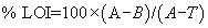 Where: A
= initial mass of crucible and sample before ignition (g); B = mass
of crucible and glass residue after ignition (g); and T = tare mass
of crucible, (g) (see Note 2).
Where: A
= initial mass of crucible and sample before ignition (g); B = mass
of crucible and glass residue after ignition (g); and T = tare mass
of crucible, (g) (see Note 2).
5.2 Report the percent LOI of the glass mat to the nearest 0.1 percent.
6.0 PrecisionThe repeatability of this test method for measurements on adjacent specimens from the same sample of mat is better than 1 percent.
Table 1 to Subpart IIII of Part 63 - Operating Limits for Capture Systems and Add-On Control Devices
40:14.0.1.1.1.17.275.36.106 :
Table 1 to Subpart IIII of Part 63 - Operating Limits for Capture Systems and Add-On Control DevicesIf you are required to comply with operating limits by § 63.3093, you must comply with the applicable operating limits in the following table
| For the following device ... | You must meet the following operating limit ... | And you must demonstrate continuous compliance with the operating limit by |
|---|---|---|
| 1. Thermal oxidizer | a. The average combustion temperature in any 3-hour period must not fall below the combustion temperature limit established according to § 63.3167(a) | i. Collecting the combustion
temperature data according to § 63.3168(c); ii. Reducing the data to 3-hour block averages; and iii. Maintaining the 3-hour average combustion temperature at or above temperature limit. |
| 2. Catalytic oxidizer | a. The average temperature measured just before the catalyst bed in any 3-hour period must not fall below the limit established according to § 63.3167(b); and either | i. Collecting the temperature
data temperature according to § 63.3168(c); ii. Reducing the data to 3-hour block averages; and iii. Maintaining the 3-hour average temperature before the catalyst bed at or above the temperature limit. |
| b. Ensure that the average temperature difference across the catalyst bed in any 3-hour period does not fall below the temperature difference limit established according to § 63.3167(b)(2); or | i. Collecting the temperature
data according to § 63.3168(c); ii. Reducing the data to 3-hour block averages; and iii. Maintaining the 3-hour average temperature difference at or above the temperature difference limit; or |
|
| c. Develop and implement an inspection and maintenance plan according to § 63.3167(b)(4) | i. Maintaining an up-to-date inspection maintenance plan, records of annual catalyst activity checks, records of monthly inspections of the oxidizer system, and records of the annual internal inspections of the catalyst bed. If a problem is discovered during a monthly or annual inspection required by § 63.3167(b)(4), you must take corrective action as soon as practicable consistent with the manufacturer's recommendations. | |
| 3. Regenerative carbon adsorber | a. The total regeneration desorbing gas (e.g., steam or nitrogen) mass flow for each carbon bed regeneration cycle must not fall below the total regeneration desorbing gas mass flow limit established according to § 63.3167(c) | i. Measuring the total
regeneration desorbing gas (e.g., steam or nitrogen) mass flow for
each regeneration cycle according to § 63.3168(d); and ii. Maintaining the total regeneration desorbing gas mass flow at or above the mass flow limit. |
| b. The temperature of the carbon bed after completing each regeneration and any cooling cycle must not exceed the carbon bed temperature limit established according to § 63.3167(c) | i. Measuring the temperature
of the carbon bed after completing each regeneration and any
cooling cycle according to § 63.3168(d); and ii. Operating the carbon beds such that each carbon bed is not returned to service until completing each regeneration and any cooling cycle until the recorded temperature of the carbon bed is at or below the temperature limit. |
|
| 4. Condenser | a. The average condenser outlet (product side) gas temperature in any 3-hour period must not exceed the temperature limit established according to § 63.3167(d) | i. Collecting the condenser
outlet (product side) gas temperature according to §
63.3168(e); ii. Reducing the data to 3-hour block averages; and iii. Maintaining the 3-hour average gas temperature at the outlet at or below the temperature limit. |
| 5. Concentrators, including zeolite wheels and rotary carbon adsorbers | a. The average desorption gas inlet temperature in any 3-hour period must not fall below the limit established according to § 63.3167(e) | i. Collecting the temperature
data according to § 63.3168(f); ii. Reducing the data to 3-hour block averages; and iii. maintaining the 3-hour average temperature at or above the temperature limit. |
| 6. Emission capture system that is a PTE | a. The direction of the air
flow at all times must be into the enclosure; and either b. The average facial velocity of air through all natural draft openings in the enclosure must be at least 200 feet per minute; or c. The pressure drop across the enclosure must be at least 0.007 inch water, as established in Method 204 of appendix M to 40 CFR part 51 |
i. Collecting the direction of
air flow, and either the facial velocity of air through all natural
draft openings according to § 63.3168(g)(1) or the pressure drop
across the enclosure according to § 63.3168(g)(2); and ii. Maintaining the facial velocity of air flow through all natural draft openings or the pressure drop at or above the facial velocity limit or pressure drop limit, and maintaining the direction of air flow into the enclosure at all times. |
| 7. Emission capture system that is not a PTE | a. The average gas volumetric flow rate or duct static pressure in each duct between a capture device and add-on control device inlet in any 3-hour period must not fall below the average volumetric flow rate or duct static pressure limit established for that capture device according to § 63.3167(f). This applies only to capture devices that are not part of a PTE that meets the criteria of § 63.3165(a) and that are not capturing emissions from a downdraft spray booth or from a flashoff area or bake oven associated with a downdraft spray booth | i. Collecting the gas
volumetric flow rate or duct static pressure for each capture
device according to § 63.3168(g); ii. Reducing the data to 3-hour block averages; and iii. Maintaining the 3-hour average gas volumetric flow rate or duct static pressure for each capture device at or above the gas volumetric flow rate or duct static pressure limit. |
Table 2 to Subpart IIII of Part 63 - Applicability of General Provisions to Subpart IIII of Part 63
40:14.0.1.1.1.17.275.36.107 :
Table 2 to Subpart IIII of Part 63 - Applicability of General Provisions to Subpart IIII of Part 63You must comply with the applicable General Provisions requirements according to the following table:
| Citation | Subject | Applicable to subpart IIII | Explanation |
|---|---|---|---|
| § 63.1(a)(1)-(12) | General Applicability | Yes | |
| § 63.1(b)(1)-(3) | Initial Applicability Determination | Yes | Applicability to subpart IIII is also specified in § 63.3081. |
| § 63.1(c)(1) | Applicability After Standard Established | Yes | |
| § 63.1(c)(2) | Applicability of Permit Program for Area Sources | No | Area sources are not subject to subpart IIII. |
| § 63.1(c)(5) | Extensions and Notifications | Yes | |
| § 63.1(c)(6) | Reclassification | Yes | |
| § 63.1(e) | Applicability of Permit Program Before Relevant Standard is Set | Yes | |
| § 63.2 | Definitions | Yes | Additional definitions are specified in § 63.3176. |
| § 63.3 | Units and Abbreviations | Yes | |
| § 63.4(a)(1)-(2) | Prohibited Activities | Yes | |
| § 63.4(b)-(c) | Circumvention/Fragmentation | Yes | |
| § 63.5(a) | Preconstruction Review Applicability | Yes | |
| § 63.5(b)(1), (3), (4), (6) | Requirements for Existing, Newly Constructed, and Reconstructed Sources | Yes | |
| § 63.5(d)(1)(i)-(ii)(F), (d)(1)(ii)(H), (d)(1)(ii)(J), (d)(1)(iii), (d)(2)-(4) | Application for Approval of Construction/Reconstruction | Yes | |
| § 63.5(e) | Approval of Construction/Reconstruction | Yes | |
| § 63.5(f) | Approval of Construction/Reconstruction Based on Prior State Review | Yes | |
| § 63.6(a) | Compliance With Standards and Maintenance Requirements - Applicability | Yes | |
| § 63.6(b)(1)-(5), (b)(7) | Compliance Dates for New and Reconstructed Sources | Yes | Section 63.3083 specifies the compliance dates. |
| § 63.6(c)(1), (2), (5) | Compliance Dates for Existing Sources | Yes | Section 63.3083 specifies the compliance dates. |
| § 63.6(e)(1)(i)-(ii) | Operation and Maintenance | Yes before January 5, 2021. No on and after January 5, 2021 | See § 63.3100(d) for general duty requirement. |
| § 63.6(e)(1)(iii) | Operation and Maintenance | Yes | |
| § 63.6(e)(3)(i), (e)(3)(iii)-(ix) | SSMP | Yes before January 5, 2021. No on and after January 5, 2021 | |
| § 63.6(f)(1) | Compliance Except During SSM | Yes before January 5, 2021. No on and after January 5, 2021 | |
| § 63.6(f)(2)-(3) | Methods for Determining Compliance | Yes | |
| § 63.6(g) | Use of an Alternative Standard | Yes | |
| § 63.6(h) | Compliance With Opacity/Visible Emission Standards | No | Subpart IIII does not establish opacity standards and does not require continuous opacity monitoring systems (COMS). |
| § 63.6(i)(1)-(14), (16) | Extension of Compliance | Yes | |
| 63.6(j) | Presidential Compliance Exemption | Yes | |
| § 63.7(a)(1) | Performance Test Requirements - Applicability | Yes | Applies to all affected sources. Additional requirements for performance testing are specified in §§ 63.3164 and 63.3166. |
| § 63.7(a)(2) except (a)(2)(i)-(viii) | Performance Test Requirements - Dates | Yes | Applies only to performance tests for capture system and control device efficiency at sources using these to comply with the standards. Section 63.3160 specifies the schedule for performance test requirements that are earlier than those specified in § 63.7(a)(2). |
| § 63.7(a)(3)-(4) | Performance Tests Required By the Administrator, Force Majeure | Yes | |
| § 63.7(b)-(d) | Performance Test Requirements - Notification, Quality Assurance, Facilities Necessary for Safe Testing Conditions During Test | Yes | Applies only to performance tests for capture system and add-on control device efficiency at sources using these to comply with the standards. |
| § 63.7(e)(1) | Conduct of performance tests | Yes before January 5, 2021. No on and after January 5, 2021 | See § 63.3164. |
| § 63.7(e)(2)-(4) | Conduct of performance tests | Yes | |
| § 63.7(f) | Performance Test Requirements - Use of Alternative Test Method | Yes | Applies to all test methods except those used to determine capture system efficiency. |
| § 63.7(g)-(h) | Performance Test Requirements - Data Analysis, Recordkeeping, Reporting, Waiver of Test | Yes | Applies only to performance tests for capture system and add-on control device efficiency at sources using these to comply with the standards. |
| § 63.8(a)(1)-(2) | Monitoring Requirements - Applicability | Yes | Applies only to monitoring of capture system and add-on control device efficiency at sources using these to comply with the standards. Additional requirements for monitoring are specified in § 63.3168. |
| § 63.8(a)(4) | Additional Monitoring Requirements | No | Subpart IIII does not have monitoring requirements for flares. |
| § 63.8(b) | Conduct of Monitoring | Yes | |
| § 63.8(c)(1) | Continuous Monitoring Systems (CMS) Operation and Maintenance | Yes before January 5, 2021. No on and after January 5, 2021 | Section 63.3168 specifies the requirements for the operation of CMS for capture systems and add-on control devices at sources using these to comply. |
| 63.8(c)(2)-(3) | CMS Operation and Maintenance | Yes | Applies only to monitoring of capture system and add-on control device efficiency at sources using these to comply with the standards. Additional requirements for CMS operations and maintenance are specified in § 63.3168. |
| § 63.8(c)(4) | CMS | No | Section 63.3168 specifies the requirements for the operation of CMS for capture systems and add-on control devices at sources using these to comply with the standards. |
| § 63.8(c)(5) | COMS | No | Subpart IIII does not have opacity or visible emission standards. |
| § 63.8(c)(6) | CMS Requirements | No | Section 63.3168 specifies the requirements for monitoring systems for capture systems and add-on control devices at sources using these to comply with the standards. |
| § 63.8(c)(7) | CMS Out-of-Control Periods | Yes | |
| § 63.8(c)(8) | CMS Out-of-Control Periods Reporting | No | Section 63.3120 requires reporting of CMS out-of-control periods. |
| § 63.8(d)-(e) | Quality Control Program and CMS Performance Evaluation | No | Subpart IIII does not require the use of continuous emissions monitoring systems. |
| § 63.8(f)(1)-(5) | Use of an Alternative Monitoring Method | Yes | |
| § 63.8(f)(6) | Alternative to Relative Accuracy Test | No | Subpart IIII does not require the use of CEMS. |
| § 63.8(g) | Data Reduction | No | Sections 63.3167 and 63.3168 specify monitoring data reduction. |
| § 63.9(a) | Notification Requirements | Yes | |
| § 63.9(b)(1)-(2) | Initial Notifications | Yes | |
| § 63.9(b)(4)(i), (b)(4)(v), (b)(5) | Application for Approval of Construction or Reconstruction | Yes | |
| § 63.9(c) | Request for Extension of Compliance | Yes | |
| § 63.9(d) | Special Compliance Requirement Notification | Yes | |
| § 63.9(e) | Notification of Performance Test | Yes | Applies only to capture system and add-on control device performance tests at sources using these to comply with the standards. |
| § 63.9(f) | Notification of Visible Emissions/Opacity Test | No | Subpart IIII does not have opacity or visible emission standards. |
| § 63.9(g) | Additional Notifications When Using CMS | No | Subpart IIII does not require the use of CEMS. |
| § 63.9(h)(1)-(3), (5)-(6) | Notification of Compliance Status | Yes | Section 63.3110 specifies the dates for submitting the notification of compliance status. |
| § 63.9(i) | Adjustment of Submittal Deadlines | Yes | |
| § 63.9(j) | Change in Previous Information | Yes | |
| § 63.9(k) | Electronic reporting procedures | Yes | Only as specified in § 63.9(j). |
| § 63.10(a) | Recordkeeping/Reporting - Applicability and General Information | Yes | |
| § 63.10(b)(1) | General Recordkeeping Requirements | Yes | Additional requirements are specified in §§ 63.3130 and 63.3131. |
| § 63.10(b)(2)(i)-(ii) | Recordkeeping of Occurrence and Duration of Startups and Shutdowns and of Failures to Meet Standards | Yes before January 5, 2021. No on and after January 5, 2021 | See 63.3130(g). |
| § 63.10(b)(2)(iii) | Recordkeeping Relevant to Maintenance of Air Pollution Control and Monitoring Equipment | Yes | |
| § 63.10(b)(2)(iv)-(v) | Actions Taken to Minimize Emissions During SSM | Yes before January 5, 2021. No on and after January 5, 2021 | See § 63.3130(g)(4) for a record of actions taken to minimize emissions during a deviation from the standard. |
| § 63.10(b)(2)(vi) | Recordkeeping for CMS Malfunctions | Yes before January 5, 2021. No on and after January 5, 2021 | See § 63.3130(g) for records of periods of deviation from the standard, including instances where a CMS is inoperative or out-of-control. |
| § 63.10(b)(2)(vii)-(xi) | Records | Yes | |
| § 63.10(b)(2)(xii) | Records | Yes | |
| § 63.10(b)(2)(xiii) | No | Subpart IIII does not require the use of CEMS. | |
| § 63.10(b)(2)(xiv) | Yes | ||
| § 63.10(b)(3) | Recordkeeping Requirements for Applicability Determinations | Yes | |
| § 63.10(c)(1)-(6) | Additional Recordkeeping Requirements for Sources with CMS | Yes | |
| § 63.10(c)(7)-(8) | Additional Recordkeeping Requirements for Sources with CMS | No | See § 63.3130(g) for records of periods of deviation from the standard, including instances where a CMS is inoperative or out-of-control. |
| § 63.10(c)(10)-(14) | Yes | ||
| § 63.10(c)(15) | Records Regarding the SSM Plan | Yes before January 5, 2021. No on and after January 5, 2021 | |
| § 63.10(d)(1) | General Reporting Requirements | Yes | Additional requirements are specified in § 63.3120. |
| § 63.10(d)(2) | Report of Performance Test Results | Yes | Additional requirements are specified in § 63.3120(b). |
| § 63.10(d)(3) | Reporting Opacity or Visible Emissions Observations | No | Subpart IIII does not require opacity or visible emissions observations. |
| § 63.10(d)(4) | Progress Reports for Sources With Compliance Extensions | Yes | |
| § 63.10(d)(5) | SSM Reports | Yes before January 5, 2021. No on and after January 5, 2021 | See 63.3120(a)(6). |
| § 63.10(e)(1)-(2) | Additional CMS Reports | No | Subpart IIII does not require the use of CEMS. |
| § 63.10(e)(3) | Excess Emissions/CMS Performance Reports | No | Section 63.3120(b) specifies the contents of periodic compliance reports. |
| § 63.10(e)(4) | COMS Data Reports | No | Subpart IIII does not specify requirements for opacity or COMS. |
| § 63.10(f) | Recordkeeping/Reporting Waiver | Yes | |
| § 63.11 | Control Device Requirements/Flares | No | Subpart IIII does not specify use of flares for compliance. |
| § 63.12 | State Authority and Delegations | Yes | |
| § 63.13 | Addresses | Yes | |
| § 63.14 | IBR | Yes | |
| § 63.15 | Availability of Information/Confidentiality | Yes |
Table 3 to Subpart IIII of Part 63 - Default Organic HAP Mass Fraction for Solvents and Solvent Blends
40:14.0.1.1.1.17.275.36.108 :
Table 3 to Subpart IIII of Part 63 - Default Organic HAP Mass Fraction for Solvents and Solvent BlendsYou may use the mass fraction values in the following table for solvent blends for which you do not have test data or manufacturer's formulation data
| Solvent/solvent blend | CAS. No. | Average organic HAP mass fraction |
Typical organic HAP, percent by mass |
|---|---|---|---|
| 1. Toluene | 108-88-3 | 1.0 | Toluene. |
| 2. Xylene(s) | 1330-20-7 | 1.0 | Xylenes, ethylbenzene. |
| 3. Hexane | 110-54-3 | 0.5 | n-hexane. |
| 4. n-Hexane | 110-54-3 | 1.0 | n-hexane. |
| 5. Ethylbenzene | 100-41-4 | 1.0 | Ethylbenzene. |
| 6. Aliphatic 140 | 0 | None. | |
| 7. Aromatic 100 | 0.02 | 1% xylene, 1% cumene. | |
| 8. Aromatic 150 | 0.09 | Naphthalene. | |
| 9. Aromatic naphtha | 64742-95-6 | 0.02 | 1% xylene, 1% cumene. |
| 10. Aromatic solvent | 64742-94-5 | 0.1 | Naphthalene. |
| 11. Exempt mineral spirits | 8032-32-4 | 0 | None. |
| 12. Ligroines (VM & P) | 8032-32-4 | 0 | None. |
| 13. Lactol spirits | 64742-89-6 | 0.15 | Toluene. |
| 14. Low aromatic white spirit | 64742-82-1 | 0 | None. |
| 15. Mineral spirits | 64742-88-7 | 0.01 | Xylenes. |
| 16. Hydrotreated naphtha | 64742-48-9 | 0 | None. |
| 17. Hydrotreated light distillate | 64742-47-8 | 0.001 | Toluene. |
| 18. Stoddard solvent | 8052-41-3 | 0.01 | Xylenes. |
| 19. Super high-flash naphtha | 64742-95-6 | 0.05 | Xylenes. |
| 20. Varsol ® solvent | 8052-49-3 | 0.01 | 0.5% xylenes, 0.5% ethylbenzene. |
| 21. VM & P naphtha | 64742-89-8 | 0.06 | 3% toluene, 3% xylene. |
| 22. Petroleum distillate mixture | 68477-31-6 | 0.08 | 4% naphthalene, 4% biphenyl. |
Table 4 to Subpart IIII of Part 63 - Default Organic HAP Mass Fraction for Petroleum Solvent Groups a
40:14.0.1.1.1.17.275.36.109 :
Table 4 to Subpart IIII of Part 63 - Default Organic HAP Mass Fraction for Petroleum Solvent Groups aYou may use the mass fraction values in the following table for solvent blends for which you do not have test data or manufacturer's formulation data
| Solvent type | Average organic HAP mass fraction |
Typical organic HAP, percent by mass |
|---|---|---|
| Aliphatic b | 0.03 | 1% Xylene, 1% Toluene, and 1% Ethylbenzene. |
| Aromatic c | 0.06 | 4% Xylene, 1% Toluene, and 1% Ethylbenzene. |
a Use this table only if the solvent blend does not match any of the solvent blends in Table 3 to this subpart, and you only know whether the blend is aliphatic or aromatic.
b E.g., Mineral Spirits 135, Mineral Spirits 150 EC, Naphtha, Mixed Hydrocarbon, Aliphatic Hydrocarbon, Aliphatic Naphtha, Naphthol Spirits, Petroleum Spirits, Petroleum Oil, Petroleum Naphtha, Solvent Naphtha, Solvent Blend.
c E.g., Medium-flash Naphtha, High-flash Naphtha, Aromatic Naphtha, Light Aromatic Naphtha, Light Aromatic Hydrocarbons, Aromatic Hydrocarbons, Light Aromatic Solvent.
Table 5 to Subpart IIII of Part 63 - List of HAP That Must Be Counted Toward Total Organic HAP Content if Present at 0.1 Percent or More by Mass
40:14.0.1.1.1.17.275.36.110 :
Table 5 to Subpart IIII of Part 63 - List of HAP That Must Be Counted Toward Total Organic HAP Content if Present at 0.1 Percent or More by Mass| Chemical name | CAS No. |
|---|---|
| 1,1,2,2-Tetrachloroethane | 79-34-5 |
| 1,1,2-Trichloroethane | 79-00-5 |
| 1,1-Dimethylhydrazine | 57-14-7 |
| 1,2-Dibromo-3-chloropropane | 96-12-8 |
| 1,2-Diphenylhydrazine | 122-66-7 |
| 1,3-Butadiene | 106-99-0 |
| 1,3-Dichloropropene | 542-75-6 |
| 1,4-Dioxane | 123-91-1 |
| 2,4,6-Trichlorophenol | 88-06-2 |
| 2,4/2,6-Dinitrotoluene (mixture) | 25321-14-6 |
| 2,4-Dinitrotoluene | 121-14-2 |
| 2,4-Toluene diamine | 95-80-7 |
| 2-Nitropropane | 79-46-9 |
| 3,3′-Dichlorobenzidine | 91-94-1 |
| 3,3′-Dimethoxybenzidine | 119-90-4 |
| 3,3′-Dimethylbenzidine | 119-93-7 |
| 4,4′-Methylene bis(2-chloroaniline) | 101-14-4 |
| Acetaldehyde | 75-07-0 |
| Acrylamide | 79-06-1 |
| Acrylonitrile | 107-13-1 |
| Allyl chloride | 107-05-1 |
| alpha-Hexachlorocyclohexane (a-HCH) | 319-84-6 |
| Aniline | 62-53-3 |
| Benzene | 71-43-2 |
| Benzidine | 92-87-5 |
| Benzotrichloride | 98-07-7 |
| Benzyl chloride | 100-44-7 |
| beta-Hexachlorocyclohexane (b-HCH) | 319-85-7 |
| Bis(2-ethylhexyl)phthalate | 117-81-7 |
| Bis(chloromethyl)ether | 542-88-1 |
| Bromoform | 75-25-2 |
| Captan | 133-06-2 |
| Carbon tetrachloride | 56-23-5 |
| Chlordane | 57-74-9 |
| Chlorobenzilate | 510-15-6 |
| Chloroform | 67-66-3 |
| Chloroprene | 126-99-8 |
| Cresols (mixed) | 1319-77-3 |
| DDE | 3547-04-4 |
| Dichloroethyl ether | 111-44-4 |
| Dichlorvos | 62-73-7 |
| Epichlorohydrin | 106-89-8 |
| Ethyl acrylate | 140-88-5 |
| Ethylene dibromide | 106-93-4 |
| Ethylene dichloride | 107-06-2 |
| Ethylene oxide | 75-21-8 |
| Ethylene thiourea | 96-45-7 |
| Ethylidene dichloride (1,1-Dichloroethane) | 75-34-3 |
| Formaldehyde | 50-00-0 |
| Heptachlor | 76-44-8 |
| Hexachlorobenzene | 118-74-1 |
| Hexachlorobutadiene | 87-68-3 |
| Hexachloroethane | 67-72-1 |
| Hydrazine | 302-01-2 |
| Isophorone | 78-59-1 |
| Lindane (hexachlorocyclohexane, all isomers) | 58-89-9 |
| m-Cresol | 108-39-4 |
| Methylene chloride | 75-09-2 |
| Naphthalene | 91-20-3 |
| Nitrobenzene | 98-95-3 |
| Nitrosodimethylamine | 62-75-9 |
| o-Cresol | 95-48-7 |
| o-Toluidine | 95-53-4 |
| Parathion | 56-38-2 |
| p-Cresol | 106-44-5 |
| p-Dichlorobenzene | 106-46-7 |
| Pentachloronitrobenzene | 82-68-8 |
| Pentachlorophenol | 87-86-5 |
| Propoxur | 114-26-1 |
| Propylene dichloride | 78-87-5 |
| Propylene oxide | 75-56-9 |
| Quinoline | 91-22-5 |
| Tetrachloroethene | 127-18-4 |
| Toxaphene | 8001-35-2 |
| Trichloroethylene | 79-01-6 |
| Trifluralin | 1582-09-8 |
| Vinyl bromide | 593-60-2 |
| Vinyl chloride | 75-01-4 |
| Vinylidene chloride | 75-35-4 |
Appendix A to Subpart IIII of Part 63 - Determination of Capture Efficiency of Automobile and Light-Duty Truck Spray Booth Emissions From Solvent-borne Coatings Using Panel Testing
40:14.0.1.1.1.17.275.36.111 : Appendix A
Appendix A to Subpart IIII of Part 63 - Determination of Capture Efficiency of Automobile and Light-Duty Truck Spray Booth Emissions From Solvent-borne Coatings Using Panel Testing1.0 Applicability, Principle, and Summary of Procedure.
1.1 Applicability.
This procedure applies to the determination of capture efficiency of automobile and light-duty truck spray booth emissions from solvent-borne coatings using panel testing. This procedure can be used to determine capture efficiency for partially controlled spray booths (e.g., automated spray zones controlled and manual spray zones not controlled) and for fully controlled spray booths.
1.2 Principle.
1.2.1 The volatile organic compounds (VOC) associated with the coating solids deposited on a part (or panel) in a controlled spray booth zone (or group of contiguous controlled spray booth zones) partition themselves between the VOC that volatilize in the controlled spray booth zone (principally between the spray gun and the part) and the VOC that remain on the part (or panel) when the part (or panel) leaves the controlled spray booth zone. For solvent-borne coatings essentially all of the VOC associated with the coating solids deposited on a part (or panel) in a controlled spray booth zone that volatilize in the controlled spray booth zone pass through the waterwash and are exhausted from the controlled spray booth zone to the control device.
1.2.2 The VOC associated with the overspray coating solids in a controlled spray booth zone partition themselves between the VOC that volatilize in the controlled spray booth zone and the VOC that are still tied to the overspray coating solids when the overspray coating solids hit the waterwash. For solvent-borne coatings almost all of the VOC associated with the overspray coating solids that volatilize in the controlled spray booth zone pass through the waterwash and are exhausted from the controlled spray booth zone to the control device. The exact fate of the VOC still tied to the overspray coating solids when the overspray coating solids hit the waterwash is unknown. This procedure assumes that none of the VOC still tied to the overspray coating solids when the overspray coating solids hit the waterwash are captured and delivered to the control device. Much of this VOC may become entrained in the water along with the overspray coating solids. Most of the VOC that become entrained in the water along with the overspray coating solids leave the water, but the point at which this VOC leave the water is unknown. Some of the VOC still tied to the overspray coating solids when the overspray coating solids hit the waterwash may pass through the waterwash and be exhausted from the controlled spray booth zone to the control device.
1.2.3 This procedure assumes that the portion of the VOC associated with the overspray coating solids in a controlled spray booth zone that volatilizes in the controlled spray booth zone, passes through the waterwash and is exhausted from the controlled spray booth zone to the control device is equal to the portion of the VOC associated with the coating solids deposited on a part (or panel) in that controlled spray booth zone that volatilizes in the controlled spray booth zone, passes through the waterwash, and is exhausted from the controlled spray booth zone to the control device. This assumption is equivalent to treating all of the coating solids sprayed in the controlled spray booth zone as if they are deposited coating solids (i.e., assuming 100 percent transfer efficiency) for purposes of using a panel test to determine spray booth capture efficiency.
1.2.4 This is a conservative (low) assumption for the portion of the VOC associated with the overspray coating solids in a controlled spray booth zone that volatilizes in the controlled spray booth zone. Thus, this assumption results in an underestimate of conservative capture efficiency. The overspray coating solids have more travel time and distance from the spray gun to the waterwash than the deposited coating solids have between the spray gun and the part (or panel). Therefore, the portion of the VOC associated with the overspray coating solids in a controlled spray booth zone that volatilizes in the controlled spray booth zone should be greater than the portion of the VOC associated with the coating solids deposited on a part (or panel) in that controlled spray booth zone that volatilizes in that controlled spray booth zone.
1.3 Summary of Procedure.
1.3.1 A panel test is performed to determine the mass of VOC that remains on the panel when the panel leaves a controlled spray booth zone. The total mass of VOC associated with the coating solids deposited on the panel is calculated.
1.3.2 The percent of the total VOC associated with the coating solids deposited on the panel in the controlled spray booth zone that remains on the panel when the panel leaves the controlled section of the spray booth is then calculated from the ratio of the two previously determined masses. The percent of the total VOC associated with the coating solids deposited on the panel in the controlled spray booth zone that is captured and delivered to the control device equals 100 minus this percentage. (The mass of VOC associated with the coating solids deposited on the panel which is volatilized and captured in the controlled spray booth zone equals the difference between the total mass of VOC associated with the coating solids deposited on the panel and the mass of VOC remaining with the coating solids deposited on the panel when the panel leaves the controlled spray booth zone.)
1.3.3 The percent of the total VOC associated with the coating sprayed in the controlled spray booth zone that is captured and delivered to the control device is assumed to be equal to the percent of the total VOC associated with the coating solids deposited on the panel in the controlled spray booth zone that is captured and delivered to the control device. The percent of the total VOC associated with the coating sprayed in the entire spray booth that is captured and delivered to the control device can be calculated by multiplying the percent of the total VOC associated with the coating sprayed in the controlled spray booth zone that is captured and delivered to the control device by the fraction of coating sprayed in the spray booth that is sprayed in the controlled spray booth zone.
2.0 Procedure.
2.1 You may conduct panel testing to determine the capture efficiency of spray booth emissions. You must follow the instructions and calculations in this appendix A, and use the panel testing procedures in ASTM Method D5087-02 (incorporated by reference, see § 63.14), or the guidelines presented in “Protocol for Determining the Daily Volatile Organic Compound Emission Rate of Automobile and Light-Duty Truck Topcoat Operations,” EPA-450/3-88-018 (incorporated by reference, see § 63.14). You must weigh panels at the points described in section 2.5 of this appendix A and perform calculations as described in sections 3 and 4 of this appendix A. You may conduct panel tests on the production paint line in your facility or in a laboratory simulation of the production paint line in your facility.
2.2 You may conduct panel testing on representative coatings as described in “Protocol for Determining the Daily Volatile Organic Compound Emission Rate of Automobile and Light-Duty Truck Topcoat Operations,” EPA-450/3-88-018 (incorporated by reference, see § 63.14). If you panel test representative coatings, then you may calculate either a unique percent capture efficiency value for each coating grouped with that representative coating, or a composite percent capture efficiency value for the group of coatings. If you panel test each coating, then you must convert the panel test result for each coating to a unique percent capture efficiency value for that coating.
2.3 Identification of Controlled Spray Booth Zones.
You must identify each controlled spray booth zone or each group of contiguous controlled spray booth zones to be tested. (For example, a controlled bell zone immediately followed by a controlled robotic zone.) Separate panel tests are required for non-contiguous controlled spray booth zones. The flash zone between the last basecoat zone and the first clearcoat zone makes these zones non-contiguous.
2.4 Where to Apply Coating to the Panel.
If you are conducting a panel test for a single controlled spray booth zone, then you must apply coating to the panel only in that controlled spray booth zone. If you are conducting a panel test for a group of contiguous controlled spray booth zones, then you must apply coating to the panel only in that group of contiguous controlled spray booth zones.
2.5 How to Process and When to Weigh the Panel.
The instructions in this section pertain to panel testing of coating, i, or of the coating representing the group of coatings that includes coating, i.
2.5.1 You must weigh the blank panel. (Same as in bake oven panel test.) The mass of the blank panel is represented by Wblank,i (grams).
2.5.2 Apply coating, i, or the coating representing coating, i, to the panel in the controlled spray booth zone or group of contiguous controlled spray booth zones being tested (in plant test), or in a simulation of the controlled spray booth zone or group of contiguous controlled spray booth zones being tested (laboratory test).
2.5.3 Remove and weigh the wet panel as soon as the wet panel leaves the controlled spray booth zone or group of contiguous controlled spray booth zones being tested. (Different than bake oven panel test.) This weighing must be conducted quickly to avoid further evaporation of VOC. The mass of the wet panel is represented by Wwet,i (grams).
2.5.4 Return the wet panel to the point in the coating process or simulation of the coating process where it was removed for weighing.
2.5.5 Allow the panel to travel through the rest of the coating process in the plant or laboratory simulation of the coating process. You must not apply any more coating to the panel after it leaves the controlled spray booth zone (or group of contiguous controlled spray booth zones) being tested. The rest of the coating process or simulation of the coating process consists of:
2.5.5.1 All of the spray booth zone(s) or simulation of all of the spray booth zone(s) located after the controlled spray booth zone or group of contiguous controlled spray booth zones being tested and before the bake oven where the coating applied to the panel is cured,
2.5.5.2 All of the flash-off area(s) or simulation of all of the flash-off area(s) located after the controlled spray booth zone or group of contiguous controlled spray booth zones being tested and before the bake oven where the coating applied to the panel is cured, and
2.5.5.3 The bake oven or simulation of the bake oven where the coating applied to the panel is cured.
2.5.6 After the panel exits the bake oven, you must cool and weigh the baked panel. (Same as in bake oven panel test.) The mass of the baked panel is represented by Wbaked,i (grams).
3.0 Panel Calculations.
The instructions in this section pertain to panel testing of coating, i, or of the coating representing the group of coatings that includes coating, i.
3.1 The mass of coating solids (from coating, i, or from the coating representing coating, i, in the panel test) deposited on the panel equals the mass of the baked panel minus the mass of the blank panel as shown in Equation A-1.
Where: Wsdep, i = Mass of coating solids (from coating, i, or from the coating representing coating, i, in the panel test) deposited on the panel, grams.3.2 The mass of VOC (from coating, i, or from the coating representing coating, i, in the panel test) remaining on the wet panel when the wet panel leaves the controlled spray booth zone or group of contiguous controlled spray booth zones being tested equals the mass of the wet panel when the wet panel leaves the controlled spray booth zone or group of contiguous controlled spray booth zones being tested minus the mass of the baked panel as shown in Equation A-2.
Where: Wrem, i = Mass of VOC (from coating, i, or from the coating representing coating, i, in the panel test) remaining on the wet panel when the wet panel leaves the controlled spray booth zone or group of contiguous controlled spray booth zones being tested, grams.3.3 Calculate the mass of VOC (from coating, i, or from the coating representing coating, i, in the panel test) remaining on the wet panel when the wet panel leaves the controlled spray booth zone or group of contiguous controlled spray booth zones being tested per mass of coating solids deposited on the panel as shown in Equation A-3.
Where: Pm, i = Mass of VOC (from coating, i, or from the coating representing coating, i, in the panel test) remaining on the wet panel when the wet panel leaves the controlled spray booth zone or group of contiguous controlled spray booth zones being tested per mass of coating solids deposited on the panel, grams of VOC remaining per gram of coating solids deposited. Wrem, i = Mass of VOC (from coating, i, or from the coating representing coating, i, in the panel test) remaining on the wet panel when the wet panel leaves the controlled spray booth zone or group of contiguous controlled spray booth zones being tested, grams. Wsdep, i = Mass of coating solids (from coating, i, or from the coating representing coating, i, in the panel test) deposited on the panel, grams.4.0 Converting Panel Result to Percent Capture.
The instructions in this section pertain to panel testing of for coating, i, or of the coating representing the group of coatings that includes coating, i.
4.1 If you panel test representative coatings, then you may convert the panel test result for each representative coating from section 3.3 of this appendix A either to a unique percent capture efficiency value for each coating grouped with that representative coating by using coating specific values for the mass fraction coating solids and mass fraction VOC in section 4.2 of this appendix A, or to a composite percent capture efficiency value for the group of coatings by using the average values for the group of coatings for mass fraction coating solids and mass fraction VOC in section 4.2 of this appendix A. If you panel test each coating, then you must convert the panel test result for each coating to a unique percent capture efficiency value by using coating specific values for the mass fraction coating solids and mass fraction VOC in section 4.2 of this appendix A. The mass fraction of VOC in the coating and the mass fraction of solids in the coating must be determined by EPA Method 24 (appendix A-7 to 40 CFR part 60) or by following the guidelines for combining analytical VOC content and formulation solvent content presented in “Protocol for Determining the Daily Volatile Organic Compound Emission Rate of Automobile and Light-Duty Truck Topcoat Operations,” EPA-450/3-88-018 (incorporated by reference, see § 63.14).
4.2 The percent of VOC for coating, i, or composite percent of VOC for the group of coatings including coating, i, associated with the coating solids deposited on the panel that remains on the wet panel when the wet panel leaves the controlled spray booth zone or group of contiguous controlled spray booth zones being tested is calculated using Equation A-4.
Where: Pvocpan, i = Percent of VOC for coating, i, or composite percent of VOC for the group of coatings including coating, i, associated with the coating solids deposited on the panel that remains on the wet panel when the wet panel leaves the controlled spray booth zone (or group of contiguous controlled spray booth zones) being tested, percent. Pm, i = Mass of VOC (from coating, i, or from the coating representing coating, i, in the panel test) remaining on the wet panel when the wet panel leaves the controlled spray booth zone or group of contiguous controlled spray booth zones being tested per mass of coating solids deposited on the panel, grams of VOC remaining per gram of coating solids deposited. Ws, i = Mass fraction of coating solids for coating, i, or average mass fraction of coating solids for the group of coatings including coating, i, grams coating solids per gram coating, determined by EPA Method 24 (appendix A-7 to 40 CFR part 60) or by following the guidelines for combining analytical VOC content and formulation solvent content presented in “Protocol for Determining the Daily Volatile Organic Compound Emission Rate of Automobile and Light-Duty Truck Topcoat Operations,” EPA-450/3-88-018 (incorporated by reference, see § 63.14). Wvocc, i = Mass fraction of VOC in coating, i, or average mass fraction of VOC for the group of coatings including coating, i, grams VOC per grams coating, determined by EPA Method 24 (appendix A-7 to 40 CFR part 60) or the guidelines for combining analytical VOC content and formulation solvent content presented in “Protocol for Determining the Daily Volatile Organic Compound Emission Rate of Automobile and Light-Duty Truck Topcoat Operations,” EPA-450/3-88-018 (incorporated by reference, see § 63.14).4.3 The percent of VOC for coating, i, or composite percent of VOC for the group of coatings including coating, i, associated with the coating sprayed in the controlled spray booth zone (or group of contiguous controlled spray booth zones) being tested that is captured in the controlled spray booth zone or group of contiguous controlled spray booth zones being tested, CEzone,i (percent), is calculated using Equation A-5.
Where: CEzone, i = Capture efficiency for coating, i, or for the group of coatings including coating, i, in the controlled spray booth zone or group of contiguous controlled spray booth zones being tested as a percentage of the VOC in the coating, i, or of the group of coatings including coating, i, sprayed in the controlled spray booth zone or group of contiguous controlled spray booth zones being tested, percent.4.4 Calculate the percent of VOC for coating, i, or composite percent of VOC for the group of coatings including coating, i, associated with the entire volume of coating, i, or with the total volume of all of the coatings grouped with coating, i, sprayed in the entire spray booth that is captured in the controlled spray booth zone or group of contiguous controlled spray booth zones being tested, using Equation A-6. The volume of coating, i, or of the group of coatings including coating, i, sprayed in the controlled spray booth zone or group of contiguous controlled spray booth zones being tested, and the volume of coating, i, or of the group of coatings including coating, i, sprayed in the entire spray booth may be determined from gun on times and fluid flow rates or from direct measurements of coating usage.
Where: CEi = Capture efficiency for coating, i, or for the group of coatings including coating, i, in the controlled spray booth zone (or group of contiguous controlled spray booth zones) being tested as a percentage of the VOC in the coating, i, or of the group of coatings including coating, i, sprayed in the entire spray booth in which the controlled spray booth zone (or group of contiguous controlled spray booth zones) being tested, percent. Vzone, i = Volume of coating, i, or of the group of coatings including coating, i, sprayed in the controlled spray booth zone or group of contiguous controlled spray booth zones being tested, liters. Vbooth, i = Volume of coating, i, or of the group of coatings including coating, i, sprayed in the entire spray booth containing the controlled spray booth zone (or group of contiguous controlled spray booth zones) being tested, liters.4.5 If you conduct multiple panel tests for the same coating or same group of coatings in the same spray booth (either because the coating or group of coatings is controlled in non-contiguous zones of the spray booth, or because you choose to conduct separate panel tests for contiguous controlled spray booth zones), then you may add the result from section 4.4 for each such panel test to get the total capture efficiency for the coating or group of coatings over all of the controlled zones in the spray booth for the coating or group of coatings.
[69 FR 22623, Apr. 26, 2004, as amended at 85 FR 41137, July 8, 2020]Table 1 to Subpart JJJJ of Part 63 - Operating Limits if Using Add-On Control Devices and Capture System
40:14.0.1.1.1.18.281.15.112 :
Table 1 to Subpart JJJJ of Part 63 - Operating Limits if Using Add-On Control Devices and Capture SystemIf you are required to comply with operating limits by § 63.3321, you must comply with the applicable operating limits in the following table:
| For the following device: | You must meet the following operating limit: | And you must demonstrate continuous compliance with operating limits by: |
|---|---|---|
| 1. Thermal oxidizer | a. The average combustion temperature in any 3-hour period must not fall more than 50 °F below the combustion temperature limit established according to § 63.3360(e)(3)(i) | i. Collecting the combustion
temperature data according to § 63.3350(e)(10); ii. Reducing the data to 3-hour block averages; and |
| iii. Maintain the 3-hour average combustion temperature at or above the temperature limit. | ||
| 2. Catalytic oxidizer | a. The average temperature at the inlet to the catalyst bed in any 3-hour period must not fall more than 50 degrees Fahrenheit below the combustion temperature limit established according to § 63.3360(e)(3)(ii) | i. Collecting the catalyst bed
inlet temperature data according to § 63.3350(e)(10); ii. Reducing the data to 3-hour block averages; and iii. Maintain the 3-hour average catalyst bed inlet temperature at or above the temperature limit. |
| b. The temperature rise across the catalyst bed must not fall below 80 percent of the limit established according to § 63.3360(e)(3)(ii), provided that the minimum temperature is always 50 degrees Fahrenheit above the catalyst's ignition temperature | i. Collecting the catalyst bed
inlet and outlet temperature data according to §
63.3350(e)(10); ii. Reducing the data to 3-hour block averages; and iii. Maintain the 3-hour average temperature rise across the catalyst bed at or above the limit, and maintain the minimum temperature at least 50 degrees Fahrenheit above the catalyst's ignition temperature |
|
| 3. Emission capture system | Submit monitoring plan to the Administrator that identifies operating parameters to be monitored according to § 63.3350(f) | Conduct monitoring according to the plan (§ 63.3350(f)(3)). |
Table 2 to Subpart JJJJ of Part 63 - Applicability of 40 CFR Part 63 General Provisions to Subpart JJJJ
40:14.0.1.1.1.18.281.15.113 :
Table 2 to Subpart JJJJ of Part 63 - Applicability of 40 CFR Part 63 General Provisions to Subpart JJJJYou must comply with the applicable General Provisions requirements according to the following table:
| General provisions reference | Applicable to subpart JJJJ | Explanation |
|---|---|---|
| § 63.1(a)(1)-(4) | Yes | |
| § 63.1(a)(5) | No | Reserved. |
| § 63.1(a)(6)-(8) | Yes | |
| § 63.1(a)(9) | No | Reserved. |
| § 63.1(a)(10)-(14) | Yes | |
| § 63.1(b)(1) | No | Subpart JJJJ specifies applicability. |
| § 63.1(b)(2)-(3) | Yes | |
| § 63.1(c)(1) | Yes | |
| § 63.1(c)(2) | No | Area sources are not subject to emission standards of subpart JJJJ. |
| § 63.1(c)(3) | No | Reserved. |
| § 63.1(c)(4) | Yes | |
| § 63.1(c)(5) | Yes | |
| § 63.1(c)(6) | Yes | |
| § 63.1(d) | No | Reserved. |
| § 63.1(e) | Yes | |
| § 63.2 | Yes | Additional definitions in subpart JJJJ. |
| § 63.3(a)-(c) | Yes | |
| § 63.4(a)(1)-(3) | Yes | |
| § 63.4(a)(4) | No | Reserved. |
| § 63.4(a)(5) | Yes | |
| § 63.4(b)-(c) | Yes | |
| § 63.5(a)(1)-(2) | Yes | |
| § 63.5(b)(1) | Yes | |
| § 63.5(b)(2) | No | Reserved. |
| § 63.5(b)(3)-(6) | Yes | |
| § 63.5(c) | No | Reserved. |
| § 63.5(d) | Yes | |
| § 63.5(e) | Yes | |
| § 63.5(f) | Yes | |
| § 63.6(a) | Yes | Applies only when capture and control system is used to comply with the standard. |
| § 63.6(b)(1)-(5) | No | § 63.3330 specifies compliance dates. |
| § 63.6(b)(6) | No | Reserved. |
| § 63.6(b)(7) | Yes | |
| § 63.6(c)(1)-(2) | Yes | |
| § 63.6(c)(3)-(4) | No | Reserved. |
| § 63.6(c)(5) | Yes | |
| § 63.6(d) | No | Reserved. |
| § 63.6(e)(1)(i) | Depends, see explanation | No, for new or reconstructed sources which commenced construction or reconstruction after September 19, 2019, see § 63.3340(a) for general duty requirement. Yes, for all other affected sources before July 9, 2021, and No thereafter, see § 63.3340(a) for general duty requirement. |
| § 63.6(e)(1)(ii) | Depends, see explanation | No, for new or reconstructed sources which commenced construction or reconstruction after September 19, 2019. Yes, for all other affected sources before July 9, 2021, and No thereafter. |
| § 63.6(e)(1)(iii) | Yes | |
| § 63.6(e)(2) | No | Reserved. |
| § 63.6(e)(3) | Depends, see explanation | No, for new or reconstructed sources which commenced construction or reconstruction after September 19, 2019. Yes, for all other affected sources before July 9, 2021, and No thereafter. |
| § 63.6(f)(1) | Depends, see explanation | No, for new or reconstructed sources which commenced construction or reconstruction after September 19, 2019. Yes, for all other affected sources before July 9, 2021, and No thereafter. |
| § 63.6(f)(2)-(3) | Yes | |
| § 63.6(g) | Yes | |
| § 63.6(h) | No | Subpart JJJJ does not require continuous opacity monitoring systems (COMS). |
| § 63.6(i)(1)-(14) | Yes | |
| § 63.6(i)(15) | No | Reserved. |
| § 63.6(i)(16) | Yes | |
| § 63.6(j) | Yes | |
| § 63.7(a)-(d) | Yes | |
| § 63.7(e)(1) | No | See § 63.3360(e)(2). |
| § 63.7(e)(2)-(3) | Yes | |
| § 63.7(f)-(h) | Yes | |
| § 63.8(a)(1)-(2) | Yes | |
| § 63.8(a)(3) | No | Reserved. |
| § 63.8(a)(4) | No | Subpart JJJJ does not have monitoring requirements for flares. |
| § 63.8(b) | Yes | |
| § 63.8(c)(1) and § 63.8(c)(1)(i) | Depends, see explanation | No, for new or reconstructed sources which commenced construction or reconstruction after September 19, 2019, see § 63.3340(a) for general duty requirement. Yes, for all other affected sources before July 9, 2021, and No thereafter, see § 63.3340(a) for general duty requirement. |
| § 63.8(c)(1)(ii) | Yes | § 63.8(c)(1)(ii) only applies if you use capture and control systems. |
| § 63.8(c)(1)(iii) | Depends, see explanation | No, for new or reconstructed sources which commenced construction or reconstruction after September 19, 2019. Yes, for all other affected sources before July 9, 2021, and No thereafter. |
| § 63.8(c)(2)-(3) | Yes | See § 63.3350(e)(10)(iv) for temperature sensor validation procedures |
| § 63.8(c)(4) | No | § 63.3350 specifies the requirements for the operation of CMS for capture systems and add-on control devices at sources using these to comply. |
| § 63.8(c)(5) | No | Subpart JJJJ does not require COMS. |
| § 63.8(c)(6)-(8) | Yes | Provisions for COMS are not applicable. |
| § 63.8(d)(1)-(2) | Yes | Refer to § 63.3350(e)(5) for CPMS quality control procedures to be included in the quality control program. |
| § 63.8(d)(3) | No | § 63.3350(e)(5) specifies the program of corrective action. |
| § 63.8(e)-(f) | Yes | § 63.8(e)(2) does not apply to CPMS. § 63.8(f)(6) only applies if you use CEMS. |
| § 63.8(g) | Yes | Only applies if you use CEMS. |
| § 63.9(a) | Yes | |
| § 63.9(b)(1) | Yes | |
| § 63.9(b)(2) | Yes | Except § 63.3400(b)(1) requires submittal of initial notification for existing affected sources no later than 1 year before compliance date. |
| § 63.9(b)(3)-(5) | Yes | |
| § 63.9(c)-(e) | Yes | |
| § 63.9(f) | No | Subpart JJJJ does not require opacity and visible emissions observations. |
| § 63.9(g) | Yes | Provisions for COMS are not applicable. |
| § 63.9(h)(1)-(3) | Yes | |
| § 63.9(h)(4) | No | Reserved. |
| § 63.9(h)(5)-(6) | Yes | |
| § 63.9(i) | Yes | |
| § 63.9(j) | Yes | |
| § 63.9(k) | Yes | Only as specified in § 63.9(j). |
| § 63.10(a) | Yes | |
| § 63.10(b)(1) | Yes | |
| § 63.10(b)(2)(i) | Depends, see explanation | No, for new or reconstructed sources which commenced construction or reconstruction after September 19, 2019. Yes, for all other affected sources before July 9, 2021, and No thereafter. |
| § 63.10(b)(2)(ii) | No | See § 63.3410 for recordkeeping of relevant information. |
| § 63.10(b)(2)(iii) | Yes | § 63.10(b)(2)(iii) only applies if you use a capture and control system. |
| § 63.10(b)(2)(iv)-(v) | Depends, see explanation | No, for new or reconstructed sources which commenced construction or reconstruction after September 19, 2019. Yes, for all other affected sources before July 9, 2021, and No thereafter. |
| § 63.10(b)(2)(vi)-(xiv) | Yes | |
| § 63.10(b)(3) | Yes | |
| § 63.10(c)(1) | Yes | |
| § 63.10(c)(2)-(4) | No | Reserved. |
| § 63.10(c)(5)-(8) | Yes | |
| § 63.10(c)(9) | No | Reserved. |
| § 63.10(c)(10)-(14) | Yes | |
| § 63.10(c)(15) | Depends, see explanation | No, for new or reconstructed sources which commenced construction or reconstruction after September 19, 2019. Yes, for all other affected sources before July 9, 2021, and No thereafter. |
| § 63.10(d)(1)-(2) | Yes | |
| § 63.10(d)(3) | No | Subpart JJJJ does not require opacity and visible emissions observations. |
| § 63.10(d)(4) | Yes | |
| § 63.10(d)(5)(i) | Depends, see explanation | No, for new or reconstructed sources which commenced construction or reconstruction after September 19, 2019. Yes, for all other affected sources before July 9, 2021, and No thereafter. See § 63.3400(c) for malfunction reporting requirements. |
| § 63.10(d)(5)(ii) | Depends, see explanation | No, for new or reconstructed sources which commenced construction or reconstruction after September 19, 2019. Yes, for all other affected sources before July 9, 2021, and No thereafter. See § 63.3400(c) for malfunction reporting requirements. |
| § 63.10(e)(1)-(2) | Yes | Provisions for COMS are not applicable. |
| § 63.10(e)(3)-(4) | No | Subpart JJJJ does not require opacity and visible emissions observations. |
| § 63.10(f) | Yes | |
| § 63.11 | No | Subpart JJJJ does not specify use of flares for compliance. |
| § 63.12 | Yes | |
| § 63.13 | Yes | |
| § 63.14 | Yes | Subpart JJJJ includes provisions for alternative ASME and ASTM test methods that are incorporated by reference. |
| § 63.15 | Yes | |
| § 63.16 | Yes |
Table 1 to Subpart KKKK of Part 63 - Emission Limits for New or Reconstructed Affected Sources
40:14.0.1.1.1.19.290.39.114 :
Table 1 to Subpart KKKK of Part 63 - Emission Limits for New or Reconstructed Affected SourcesYou must comply with the emission limits that apply to your affected source in the following table as required by § 63.3490(a) through (c).
| If you apply surface coatings to metal cans or metal can parts in this subcategory ... | Then for all coatings of this type ... | You must meet the following organic HAP emission limit in kg HAP/liter solids (lbs HAP/gal solids): a b |
|---|---|---|
| 1. One and two-piece draw and iron can body coating | a. Two-piece beverage cans -
all coatings b. Two-piece food cans - all coatings c. One-piece aerosol cans - all coatings |
0.04 (0.31). 0.06 (0.50). 0.08 (0.65). |
| 2. Sheetcoating | Sheetcoating | 0.02 (0.17). |
| 3. Three-piece can assembly | a. Inside spray | 0.12 (1.03). |
| b. Aseptic side seam stripes on food cans | 1.48 (12.37). | |
| c. Nonaseptic side seam stripes on food cans | 0.72 (5.96). | |
| d. Side seam stripes on general line nonfood cans | 1.18 (9.84). | |
| e. Side seam stripes on aerosol cans | 1.46 (12.14). | |
| 4. End coating | a. Aseptic end seal compounds | 0.06 (0.54). |
| b. Nonaseptic end seal compounds | 0.00 (0.00). | |
| c. Repair spray coatings | 0.64 (5.34). |
a If you apply surface coatings of more than one type within any one subcategory you may calculate an OSEL according to § 63.3531(i).
b Rounding differences in specific emission limits are attributable to unit conversions.
Table 2 to Subpart KKKK of Part 63 - Emission Limits for Existing Affected Sources
40:14.0.1.1.1.19.290.39.115 :
Table 2 to Subpart KKKK of Part 63 - Emission Limits for Existing Affected SourcesYou must comply with the emission limits that apply to your affected source in the following table as required by § 63.3490(a) through (c).
| If you apply surface coatings to metal cans or metal can parts in this subcategory ... | Then for all coatings of this type ... | You must meet the following organic HAP emission limit in kg HAP/liter solids (lbs HAP/gal solids): a b |
|---|---|---|
| 1. One and two-piece draw and iron can body coating | a. Two-piece beverage cans -
all coatings b. Two-piece food cans - all coatings c. One-piece aerosol cans - all coatings |
0.07 (0.59). 0.06 (0.51). 0.12 (0.99). |
| 2. Sheetcoating | Sheetcoating | 0.03 (0.26). |
| 3. Three-piece can assembly | a. Inside spray | 0.29 (2.43). |
| b. Aseptic side seam stripes on food cans | 1.94 (16.16). | |
| c. Nonaseptic side seam stripes on food cans | 0.79 (6.57). | |
| d. Side seam stripes on general line nonfood cans | 1.18 (9.84). | |
| e. Side seam stripes on aerosol cans | 1.46 (12.14). | |
| 4. End coating | a. Aseptic end seal compounds | 0.06 (0.54). |
| b. Nonaseptic end seal compounds | 0.00 (0.00). | |
| c. Repair spray coatings | 2.06 (17.17). |
a If you apply surface coatings of more than one type within any one subcategory you may calculate an OSEL according to § 63.3531(i).
b Rounding differences in specific emission limits are attributable to unit conversions.
Table 3 to Subpart KKKK of Part 63 - Emission Limits for Affected Sources Using the Control Efficiency/Outlet Concentration Compliance Option
40:14.0.1.1.1.19.290.39.116 :
Table 3 to Subpart KKKK of Part 63 - Emission Limits for Affected Sources Using the Control Efficiency/Outlet Concentration Compliance OptionYou must comply with the emission limits that apply to your affected source in the following table as required by § 63.3490(d).
| If you use the control efficiency/outlet concentration option to comply with the emission limitations for any coating operation(s) . . . | Then you must comply with one of the following by using an emissions control system to . . . |
|---|---|
| 1. in a new or reconstructed affected source | a. reduce emissions of total
HAP, measured as THC (as carbon), a by 97 percent;
or b. limit emissions of total HAP, measured as THC (as carbon), a to 20 ppmvd at the control device outlet and use a PTE. |
| 2. in an existing affected source | a. reduce emissions of total
HAP, measured as THC (as carbon), a by 95 percent;
or b. limit emissions of total HAP, measured as THC (as carbon), a to 20 ppmvd at the control device outlet and use a PTE. |
a You may choose to subtract methane from THC as carbon measurements.
Table 4 to Subpart KKKK of Part 63 - Operating Limits If Using the Emission Rate With Add-on Controls Option or the Control Efficiency/Outlet Concentration Compliance Option
40:14.0.1.1.1.19.290.39.117 :
Table 4 to Subpart KKKK of Part 63 - Operating Limits If Using the Emission Rate With Add-on Controls Option or the Control Efficiency/Outlet Concentration Compliance OptionIf you are required to comply with operating limits by § 63.3492, you must comply with the applicable operating limits in the following table:
| For the following device . . . | You must meet the following operating limit . . . | And you must demonstrate continuous compliance with the operating limit by . . . |
|---|---|---|
| 1. Thermal oxidizer | a. The average combustion temperature in each 3-hour block period must not fall below the combustion temperature limit established according to § 63.3546(a) or § 63.3556(a). | i. Collecting the combustion
temperature data according to § 63.3547(c) or § 63.3557(c); ii. Reducing the data to 3-hour block averages; and iii. Maintaining the 3-hour block average combustion temperature at or above the temperature limit established according to § 63.3546(a) or § 63.3556(a). |
| 2. Catalytic oxidizer | a. The average temperature difference across the catalyst bed in each 3-hour period does not fall below the temperature difference limit established according to § 63.3546(b)(2) or § 63.3556(b)(2); or | i. Collecting the temperature
data according to § 63.3547(c) or § 63.3578(c); ii. Reducing the data to 3-hour block averages; and iii. Maintaining the 3-hour block average temperature difference at or above the temperature difference limit established according to § 63.3546(b)(2) or § 63.3556(b)(2). |
| b. The average temperature measured at the inlet to the catalyst bed in each 3-hour block period must not fall below the limit established according to § 63.3546(b) or § 63.3556(b); and | i. Collecting the temperature
data according to § 63.3547(c) or § 63.3557(c); and ii. Reducing the data to 3-hour block averages, and iii. Maintaining the 3-hour block average temperature at the inlet to the catalyst bed at or above the temperature limit established according to § 63.3546(b) or § 63.3556(b). |
|
| c. Develop and implement an inspection and maintenance plan according to § 63.3546(b)(4) or § 63.3556(b)(4). | Maintaining an up-to-date inspection plan, records of annual catalyst activity checks, records of monthly inspections of the oxidizer system, and records of the annual internal inspections of the catalyst bed. If a problem is discovered during a monthly or annual inspection required by § 63.3546(b)(4) or § 63.3556(b)(4), you must take corrective action as soon as practicable consistent with the manufacturer's recommendations. | |
| 3. Regenerative oxidizers | a. Develop and implement a valve inspection plan according to § 63.3546(c) or § 63.3546(c); and either | Maintaining an up-to-date valve inspection plan. If a problem is discovered during an inspection required by § 63.3556(c), or § 63.3556(c), you must take corrective action as soon as soon as practicable. |
| b. If you are using a regenerative thermal oxidizer, follow the operating limits according to 1.a of this table; or | See all applicable items in 1.a of this table. | |
| c. If you are using a regenerative catalytic oxidizer, follow the operating limits according to item 2.a of this table. | See all applicable items in 2.a, 2.b, and 2.c of this table. | |
| 4. Carbon adsorber | a. The total regeneration desorbing gas (e.g., steam or nitrogen) mass flow for each carbon bed regeneration cycle must not fall below the total regeneration desorbing gas mass flow limit established according to § 63.3546(d) or § 63.3556(d). | i. Measuring the total
regeneration desorbing gas (e.g., steam or nitrogen) mass flow for
each regeneration cycle according to § 63.3547(d) or § 63.3557(d);
and ii. Maintaining the total regeneration desorbing gas mass flow at or above the mass flow limit. |
| b. The temperature of the carbon bed, after completing each regeneration and any cooling cycle, must not exceed the carbon bed temperature limit established according to § 63.3546(d) or § 63.3556(d). | i. Measuring the temperature
of the carbon bed, after completing each regeneration and any
cooling cycle, according to § 63.3547(d) or § 63.3557(d); and ii. Operating the carbon beds such that each carbon bed is not returned to service until completing each regeneration and any cooling cycle until the recorded temperature of the carbon bed is at or below the temperature limit. |
|
| 5. Condenser | a. The average condenser outlet (product side) gas temperature in each 3-hour period must not exceed the temperature limit established according to § 63,3546(e) or § 63.3556(e). | i. Collecting the condenser
outlet (product side) gas temperature according to § 63.3547(e) or
§ 63.3557(e); ii. Reducing the data to 3-hour block averages; and iii. Maintaining the 3-hour block average gas temperature at the outlet at or below the temperature limit. |
| 6. Concentrators, including zeolite wheels and rotary carbon absorbers | a. The average inlet temperature measured from the desorption reactivation zone in each 3-hour block period must not fall below the limit established according to § 63.3546(f) or § 63.3556(f). | i. Collecting the temperature
data including zeolite inlet temperature according to §
63.3547(f) ii. Reducing the data to 3-hour block averages; and iii. Maintaining the 3-hour block average temperature at or above the temperature limit. |
| b. The indicator of performance for the desorption reactivation fan operation in each 3-hour block period must not fall outside of the range established according to § 63.3547(f) or § 63.3556(f). | i. Collecting the indicator
data according to § 63.3547(f) or § 63.3557(f); and ii. Maintaining the indicator data within the range established. |
|
| c. The nominal rotational speed of the concentrator in each 3-hour block period must not fall below the speed established according to § 63.3546(f) or § 63.3556(f). | i. Collecting the rotational
speed according to § 63.3547(f) or § 63.3557(f); ii. Reducing the speed data to 3-hour block averages; and iii. Maintaining the 3-hour block average speed at or above the rotational speed limit. |
|
| d. Develop and implement an inspection and maintenance plan according to § 63.3546(f)(3) or § 63.3556(f)(3). | Maintaining an up-to-date inspection plan, and records of annual adsorbent activity checks. The results shall be compared to historical results and/or results for new adsorbents. If a problem is discovered during the annual inspection required by § 63.3546(f)(3) or § 63.3556(f)(3), you must take corrective action as soon as practicable consistent with the manufacturer's recommendations. | |
| 7. Emission capture system that is a PTE according to § 63.3544(a) or § 63.3554(a) | a. The direction of the air flow at all times must be into the enclosure; and either | i. Collecting the direction of
air of air flow, and either the facial velocity of air through all
natural draft openings or the pressure drop across the enclosure;
and ii. Reducing the data collected each successive 15-minute period to 3-hour block averages according to § 63.3547(a)(1) and (2) or § 63.3557(a)(1) and (2), as applicable; and iii. Maintaining the 3-hour block average facial velocity of air flow through all natural draft openings or the pressure drop at or above the facial velocity limit or pressure drop limit, and maintaining the direction of air flow into the enclosure at all times. |
| b. The average facial velocity of air through all natural draft openings in the enclosure must be at least 200 feet per minute; or | See items 7.a.i and ii of this table. | |
| c. The pressure drop across the enclosure must be at least 0.007 inch H20, as established in Method 204 of appendix M to 40 CFR part 51. | See items 7.a.i and ii of this table. | |
| 8. Emission capture system that is not a PTE according to § 63.3544(a) | a. The average gas volumetric flow rate at a location upstream of the control device, or duct static pressure at a location upstream (i.e., vacuum side) of the primary fan in each duct of each capture device or upstream of the fan that is common to multiple capture devices in each 3-hour period must not fall below the average volumetric flow rate or above the duct static pressure limit established for that capture device in accordance with § 63.3546 or § 63.3556, as applicable. | i. Measuring the gas
volumetric flow at a location upstream of the control device, or
duct static pressure at a location upstream (i.e., vacuum side) of
the primary fan in each duct of each capture device upstream or
upstream of the fan that is common to multiple capture devices;
and ii. Reducing the data collected each successive 15-minute period to 3-hour block averages according to § 63.3547(a)(1) and (2) or § 63.3557(a)(1) and (2), as applicable; and iii. Maintaining the 3-hour block average gas volumetric flow rate at a location upstream of the control device, or duct static pressure at a location upstream (i.e., vacuum side) of the primary fan in each duct of each capture device or upstream of the fan that is common to multiple capture devices at or above the average gas volumetric flow rate or below the duct static pressure limit established in accordance with the performance test described in § 63.3546(g). |
Table 5 to Subpart KKKK of Part 63 - Applicability of General Provisions to Subpart KKKK
40:14.0.1.1.1.19.290.39.118 :
Table 5 to Subpart KKKK of Part 63 - Applicability of General Provisions to Subpart KKKKYou must comply with the applicable General Provisions requirements according to the following table:
| Citation | Subject | Applicable to subpart KKKK | Explanation |
|---|---|---|---|
| § 63.1(a)(1)-(4) | General Applicability | Yes | |
| § 63.1(a)(6) | Source Category Listing | Yes | |
| § 63.1(a)(10)-(12) | Timing and Overlap Clarifications | Yes | |
| § 63.1(b)(1) | Initial Applicability Determination | Yes | Applicability to subpart KKKK is also specified in § 63.3481. |
| § 63.1(b)(3) | Applicability Determination Recordkeeping | Yes | |
| § 63.1(c)(1) | Applicability after Standard Established | Yes | |
| § 63.1(c)(2) | Applicability of Permit Program for Area Sources | No | Area sources are not subject to subpart KKKK. |
| § 63.1(c)(5) | Extensions and Notifications | Yes | |
| § 63.1(c)(6) | Reclassification | Yes | |
| § 63.1(e) | Applicability of Permit Program before Relevant Standard is Set | Yes | |
| § 63.2 | Definitions | Yes | Additional definitions are specified in § 63.3561. |
| § 63.3 | Units and Abbreviations | Yes | |
| § 63.4(a)(1)-(2) | Prohibited Activities | Yes | |
| § 63.4(b)-(c) | Circumvention/Fragmentation | Yes | |
| § 63.5(a) | Construction/Reconstruction | Yes | |
| § 63.5(b)(1), (3), (4), (6) | Requirements for Existing, Newly Constructed, and Reconstructed Sources | Yes | |
| § 63.5(d)(1)(i)-(ii)(F), (d)(1)(ii)(H), (d)(1)(ii)(J), (d)(1)(iii), (d)(2)-(4) | Application for Approval of Construction/Reconstruction | Yes | |
| § 63.5(e) | Approval of Construction/Reconstruction | Yes | |
| § 63.5(f) | Approval of Construction/Reconstruction Based on Prior State Review | Yes | |
| § 63.6(a) | Compliance with Standards and Maintenance Requirements - Applicability | Yes | |
| § 63.6(b)(1)-(5), (b)(7) | Compliance Dates for New and Reconstructed Sources | Yes | Section 63.3483 specifies the compliance dates. |
| § 63.6(c)(1), (2), (5) | Compliance Dates for Existing Sources | Yes | Section 63.3483 specifies the compliance dates. |
| § 63.6(e)(1)(i)-(ii) | Operation and Maintenance | Yes before August 24, 2020, No on and after August 24, 2020 | See § 63.3500(b) for general duty requirement. |
| § 63.6(e)(1)(iii) | Operation and Maintenance | Yes | |
| § 63.6(e)(3)(i), (e)(3)(iii)-(ix) | SSMP | Yes before August 24, 2020, No on and after August 24, 2020 | |
| § 63.6(f)(1) | Compliance Except during Startup, Shutdown, and Malfunction | Yes before August 24, 2020, No on and after August 24, 2020 | |
| § 63.6(f)(2)-(3) | Methods for Determining Compliance | Yes | |
| § 63.6(g) | Use of an Alternative Standard | Yes | |
| § 63.6(h) | Compliance with Opacity/Visible Emission Standards | No | Subpart KKKK does not establish opacity standards and does not require continuous opacity monitoring systems (COMS). |
| § 63.6(i)(1)-(14) | Extension of Compliance | Yes | |
| § 63.6(i)(16) | Compliance Extensions and Administrator's Authority | Yes | |
| § 63.6(j) | Presidential Compliance Exemption | Yes | |
| § 63.7(a)(1) | Performance Test Requirements - Applicability | Yes | Applies to all affected sources. Additional requirements for performance testing are specified in §§ 63.3543, 63.3544, 63.3545, 63.3554, and 63.3555. |
| § 63.7(a)(2) except (a)(2)(i)-(viii) | Performance Test Requirements - Dates | Yes | Applies only to performance tests for capture system and control device efficiency at sources using these to comply with the standards. Sections 63.3540 and 63.3550 specify the schedule for performance test requirements that are earlier than those specified in § 63.7(a)(2). |
| § 63.7(a)(3) | Performance Tests Required by the Administrator | Yes | |
| § 63.7(b)-(d) | Performance Test Requirements - Notification, Quality Assurance, Facilities Necessary for Safe Testing, Conditions During Test | Yes | Applies only to performance tests for capture system and add-on control device efficiency at sources using these to comply with the standards. |
| § 63.7(e)(1) | Conduct of Performance Tests | Yes before August 24, 2020, No on and after August 24, 2020 | See §§ 63.3543 and 63.3553. |
| § 63.7(e)(2)-(4) | Conduct of Performance Tests | Yes | |
| § 63.7(f) | Performance Test Requirements - Use of Alternative Test Method | Yes | Applies to all test methods except those used to determine capture system efficiency. |
| § 63.7(g)-(h) | Performance Test Requirements - Data Analysis, Recordkeeping, Reporting, Waiver of Test | Yes | Applies only to performance tests for capture system and add-on control device efficiency at sources using these to comply with the standards. |
| § 63.8(a)(1)-(2) | Monitoring Requirements - Applicability | Yes | Applies only to monitoring of capture system and add-on control device efficiency at sources using these to comply with the standards. Additional requirements for monitoring are specified in §§ 63.3547 and 63.3557. |
| § 63.8(a)(4) | Additional Monitoring Requirements | No | Subpart KKKK does not have monitoring requirements for flares. |
| § 63.8(b) | Conduct of Monitoring | Yes | |
| § 63.8(c)(1) | Continuous Monitoring System (CMS) Operation and Maintenance | Yes before August 24, 2020, No on and after August 24, 2020 | Sections 63.3547 and 63.3557 specify the requirements for the operation of CMS for capture systems and add-on control devices at sources using these to comply. |
| § 63.8(c)(2)-(3) | CMS Operation and Maintenance | Yes | Applies only to monitoring of capture system and add-on control device efficiency at sources using these to comply with the standards. Additional requirements for CMS operations and maintenance are specified in §§ 63.3547 and 63.3557. |
| § 63.8(c)(4) | CMS | No | Sections 63.3547 and 63.3557 specify the requirements for the operation of CMS for capture systems and add-on control devices at sources using these to comply. |
| § 63.8(c)(5) | COMS | No | Subpart KKKK does not have opacity or visible emission standards. |
| § 63.8(c)(6) | CMS Requirements | No | Sections 63.3547 and 63.3557 specify the requirements for monitoring systems for capture systems and add-on control devices at sources using these to comply. |
| § 63.8(c)(7) | CMS Out-of-Control Periods | Yes | |
| § 63.8(c)(8) | CMS Out-of-Control Periods Reporting | No | Section 63.3511 requires reporting of CMS out of control periods. |
| § 63.8(d)-(e) | Quality Control Program and CMS Performance Evaluation | No | |
| § 63.8(f)(1)-(5) | Use of an Alternative Monitoring Method | Yes | |
| § 63.8(f)(6) | Alternative to Relative Accuracy Test | No | Section 63.8(f)(6) provisions are not applicable because subpart KKKK does not require CEMS. |
| § 63.8(g) | Data Reduction | No | Sections 63.3542, 63.3547, 63.3552 and 63.3557 specify monitoring data reduction. |
| § 63.9(a) | Notification Applicability | Yes | |
| § 63.9(b)(1)-(2) | Initial Notifications | Yes | |
| § 63.9(b)(4)(i), (b)(4)(v), (b)(5) | Application for Approval of Construction or Reconstruction | Yes | |
| § 63.9(c) | Request for Extension of Compliance | Yes | |
| § 63.9(d) | Special Compliance Requirement Notification | Yes | |
| § 63.9(e) | Notification of Performance Test | Yes | Applies only to capture system and add-on control device performance tests at sources using these to comply with the standards. |
| § 63.9(f) | Notification of Visible Emissions/Opacity Test | No | Subpart KKKK does not have opacity or visible emission standards. |
| § 63.9(g) | Additional Notifications When Using CMS | No | |
| § 63.9(h)(1)-(3) | Notification of Compliance Status | Yes | Section 63.3510 specifies the dates for submitting the notification of compliance status. |
| § 63.9(h)(5)-(6) | Clarifications | Yes | |
| § 63.9(i) | Adjustment of Submittal Deadlines | Yes | |
| § 63.9(j) | Change in Previous Information | Yes | |
| § 63.9(k) | Electronic reporting procedures | Yes | Only as specified in § 63.9(j). |
| § 63.10(a) | Recordkeeping/Reporting - Applicability and General Information | Yes | |
| § 63.10(b)(1) | General Recordkeeping Requirements | Yes | Additional requirements are specified in §§ 63.3512 and 63.3513. |
| § 63.10(b)(2)(i)-(ii) | Recordkeeping of Occurrence and Duration of Startups and Shutdowns and of Failures to Meet Standards | Yes before August 24, 2020, No on and after August 24, 2020 | See § 63.3512(i). |
| § 63.10(b)(2)(iii) | Recordkeeping Relevant to Maintenance of Air Pollution Control and Monitoring Equipment | Yes | |
| § 63.10(b)(2)(iv)-(v) | Actions Taken to Minimize Emissions During Startup, Shutdown, and Malfunction | Yes before August 24, 2020, No on and after August 24, 2020 | See § 63.3512(i)(4) for a record of actions taken to minimize emissions duration a deviation from the standard. |
| § 63.10(b)(2)(vi) | Recordkeeping for CMS Malfunctions | Yes before August 24, 2020, No on and after August 24, 2020 | See § 63.3512(i) for records of periods of deviation from the standard, including instances where a CMS is inoperative or out-of-control. |
| § 63.10(b)(2) (vii)-(xii) | Records | Yes | |
| § 63.10(b)(2) (xiii) | No | ||
| § 63.10(b)(2) (xiv) | Yes | ||
| § 63.10(b)(3) | Recordkeeping Requirements for Applicability Determinations | Yes | |
| § 63.10(c)(1) | Additional Recordkeeping Requirements for Sources with CMS | Yes | |
| § 63.10(c)(5)-(6) | Yes | ||
| § 63.10(c)(7)-(8) | Additional Recordkeeping Requirements for Sources with CMS | No | See § 63.3512(i) for records of periods of deviation from the standard, including instances where a CMS is inoperative or out-of-control. |
| § 63.10(c)(10)-(14) | Additional Recordkeeping Requirements for Sources with CMS | Yes | |
| § 63.10(c)(15) | Records Regarding the Startup, Shutdown, and Malfunction Plan | Yes before August 24, 2020, No on and after August 24, 2020 | |
| § 63.10(d)(1) | General Reporting Requirements | Yes | Additional requirements are specified in § 63.3511. |
| § 63.10(d)(2) | Report of Performance Test Results | Yes | Additional requirements are specified in § 63.3511(b). |
| § 63.10(d)(3) | Reporting Opacity or Visible Emissions Observations | No | Subpart KKKK does not require opacity or visible emissions observations. |
| § 63.10(d)(4) | Progress Reports for Sources with Compliance Extensions | Yes | |
| § 63.10(d)(5) | Startup, Shutdown, Malfunction Reports | Yes before August 24, 2020, No on and after August 24, 2020 | See § 63.3511(a)(7) and (8). |
| § 63.10(e)(1)-(2) | Additional CMS Reports | No | |
| § 63.10(e)(3) | Excess Emissions/CMS Performance Reports | No | Section 63.3511(b) specifies the contents of periodic compliance reports. |
| § 63.10(e)(4) | COMS Data Reports | No | Subpart KKKK does not specify requirements for opacity or COMS. |
| § 63.10(f) | Recordkeeping/Reporting Waiver | Yes | |
| § 63.11 | Control Device Requirements/Flares | No | Subpart KKKK does not specify use of flares for compliance. |
| § 63.12 | State Authority and Delegations | Yes | |
| § 63.13(a) | Addresses | Yes before August 24, 2020, No on and after August 24, 2020 | |
| § 63.13(b) | Submittal to State Agencies | Yes | |
| § 63.13(c) | Submittal to State Agencies | Yes before August 24, 2020, No unless the state requires the submittal via CEDRI, on and after August 24, 2020 | |
| § 63.14 | Incorporation by Reference | Yes | |
| § 63.15 | Availability of Information/Confidentiality | Yes |
Table 6 to Subpart KKKK of Part 63 - Default Organic HAP Mass Fraction for Solvents and Solvent Blends
40:14.0.1.1.1.19.290.39.119 :
Table 6 to Subpart KKKK of Part 63 - Default Organic HAP Mass Fraction for Solvents and Solvent BlendsYou may use the mass fraction values in the following table for solvent blends for which you do not have test data or manufacturer's formulation data.
| Solvent/solvent blend | CAS. No. | Average organic HAP mass fraction |
Typical organic HAP, percent by mass |
|---|---|---|---|
| 1. Toluene | 108-88-3 | 1.0 | Toluene. |
| 2. Xylene(s) | 1330-20-7 | 1.0 | Xylenes, ethylbenzene. |
| 3. Hexane | 110-54-3 | 0.5 | n-hexane. |
| 4. n-Hexane | 110-54-3 | 1.0 | n-hexane. |
| 5. Ethylbenzene | 100-41-4 | 1.0 | Ethylbenzene. |
| 6. Aliphatic 140 | 0 | None. | |
| 7. Aromatic 100 | 0.02 | 1% Xylene, 1% cumene. | |
| 8. Aromatic 150 | 0.09 | Naphthalene. | |
| 9. Aromatic naphtha | 64742-95-6 | 0.02 | 1% Xylene, 1% cumene. |
| 10. Aromatic solvent | 64742-94-5 | 0.1 | Naphthalene. |
| 11. Exempt mineral spirits | 8032-32-4 | 0 | None. |
| 12. Ligroines (VM & P) | 8032-32-4 | 0 | None. |
| 13. Lactol spirits | 64742-89-6 | 0.15 | Toluene. |
| 14. Low aromatic white spirit | 64742-82-1 | 0 | None. |
| 15. Mineral spirits | 64742-88-7 | 0.01 | Xylenes. |
| 16. Hydrotreated naphtha | 64742-48-9 | 0 | None. |
| 17. Hydrotreated light distillate | 64742-47-8 | 0.001 | Toluene. |
| 18. Stoddard solvent | 8052-41-3 | 0.01 | Xylenes. |
| 19. Super high-flash naphtha | 64742-95-6 | 0.05 | Xylenes. |
| 20. Varsol ® solvent | 8052-49-3 | 0.01 | 0.5% Xylenes, 0.5% ethylbenzene. |
| 21. VM & P naphtha | 64742-89-8 | 0.06 | 3% Toluene, 3% xylene. |
| 22. Petroleum distillate mixture | 68477-31-6 | 0.08 | 4% Naphthalene, 4% biphenyl. |
Table 7 to Subpart KKKK of Part 63 - Default Organic HAP Mass Fraction for Petroleum Solvent Groups a
40:14.0.1.1.1.19.290.39.120 :
Table 7 to Subpart KKKK of Part 63 - Default Organic HAP Mass Fraction for Petroleum Solvent Groups aYou may use the mass fraction values in the following table for solvent blends for which you do not have test data or manufacturer's formulation data.
| Solvent type | Average organic HAP mass fraction |
Typical organic HAP, percent by mass |
|---|---|---|
| Aliphatic b | 0.03 | 1% Xylene, 1% toluene, and 1% ehylbenzene. |
| Aromatic c | 0.06 | 4% Xylene, 1% toluene, and 1% ethylbenzene. |
a Use this table only if the solvent blend does not match any of the solvent blends in Table 6 to this subpart and you only know whether the blend is aliphatic or aromatic.
b E.g., Mineral Spirits 135, Mineral Spirits 150 EC, Naphtha, Mixed Hydrocarbon, Aliphatic Hydrocarbon, Aliphatic Naphtha, Naphthol Spirits, Petroleum Spirits, Petroleum Oil, Petroleum Naphtha, Solvent Naphtha, Solvent Blend.
c E.g., Medium-flash Naphtha, High-flash Naphtha, Aromatic Naphtha, Light Aromatic Naphtha, Light Aromatic Hydrocarbons, Aromatic Hydrocarbons, Light Aromatic Solvent.
Table 8 to Subpart KKKK of Part 63 - List of Hazardous Air Pollutants That Must Be Counted Toward Total Organic HAP Content if Present at 0.1 Percent or More by Mass
40:14.0.1.1.1.19.290.39.121 :
Table 8 to Subpart KKKK of Part 63 - List of Hazardous Air Pollutants That Must Be Counted Toward Total Organic HAP Content if Present at 0.1 Percent or More by Mass| Chemical name | CAS No. |
|---|---|
| 1,1,2,2-Tetrachloroethane | 79-34-5 |
| 1,1,2-Trichloroethane | 79-00-5 |
| 1,1-Dimethylhydrazine | 57-14-7 |
| 1,2-Dibromo-3-chloropropane | 96-12-8 |
| 1,2-Diphenylhydrazine | 122-66-7 |
| 1,3-Butadiene | 106-99-0 |
| 1,3-Dichloropropene | 542-75-6 |
| 1,4-Dioxane | 123-91-1 |
| 2,4,6-Trichlorophenol | 88-06-2 |
| 2,4/2,6-Dinitrotoluene (mixture) | 25321-14-6 |
| 2,4-Dinitrotoluene | 121-14-2 |
| 2,4-Toluene diamine | 95-80-7 |
| 2-Nitropropane | 79-46-9 |
| 3,3′-Dichlorobenzidine | 91-94-1 |
| 3,3′-Dimethoxybenzidine | 119-90-4 |
| 3,3′-Dimethylbenzidine | 119-93-7 |
| 4,4′-Methylene bis(2-chloroaniline) | 101-14-4 |
| Acetaldehyde | 75-07-0 |
| Acrylamide | 79-06-1 |
| Acrylonitrile | 107-13-1 |
| Allyl chloride | 107-05-1 |
| alpha-Hexachlorocyclohexane (a-HCH) | 319-84-6 |
| Aniline | 62-53-3 |
| Benzene | 71-43-2 |
| Benzidine | 92-87-5 |
| Benzotrichloride | 98-07-7 |
| Benzyl chloride | 100-44-7 |
| beta-Hexachlorocyclohexane (b-HCH) | 319-85-7 |
| Bis(2-ethylhexyl)phthalate | 117-81-7 |
| Bis(chloromethyl)ether | 542-88-1 |
| Bromoform | 75-25-2 |
| Captan | 133-06-2 |
| Carbon tetrachloride | 56-23-5 |
| Chlordane | 57-74-9 |
| Chlorobenzilate | 510-15-6 |
| Chloroform | 67-66-3 |
| Chloroprene | 126-99-8 |
| Cresols (mixed) | 1319-77-3 |
| DDE | 3547-04-4 |
| Dichloroethyl ether | 111-44-4 |
| Dichlorvos | 62-73-7 |
| Epichlorohydrin | 106-89-8 |
| Ethyl acrylate | 140-88-5 |
| Ethylene dibromide | 106-93-4 |
| Ethylene dichloride | 107-06-2 |
| Ethylene oxide | 75-21-8 |
| Ethylene thiourea | 96-45-7 |
| Ethylidene dichloride (1,1-Dichloroethane) | 75-34-3 |
| Formaldehyde | 50-00-0 |
| Heptachlor | 76-44-8 |
| Hexachlorobenzene | 118-74-1 |
| Hexachlorobutadiene | 87-68-3 |
| Hexachloroethane | 67-72-1 |
| Hydrazine | 302-01-2 |
| Isophorone | 78-59-1 |
| Lindane (hexachlorocyclohexane, all isomers) | 58-89-9 |
| m-Cresol | 108-39-4 |
| Methylene chloride | 75-09-2 |
| Naphthalene | 91-20-3 |
| Nitrobenzene | 98-95-3 |
| Nitrosodimethylamine | 62-75-9 |
| o-Cresol | 95-48-7 |
| o-Toluidine | 95-53-4 |
| Parathion | 56-38-2 |
| p-Cresol | 106-44-5 |
| p-Dichlorobenzene | 106-46-7 |
| Pentachloronitrobenzene | 82-68-8 |
| Pentachlorophenol | 87-86-5 |
| Propoxur | 114-26-1 |
| Propylene dichloride | 78-87-5 |
| Propylene oxide | 75-56-9 |
| Quinoline | 91-22-5 |
| Tetrachloroethene | 127-18-4 |
| Toxaphene | 8001-35-2 |
| Trichloroethylene | 79-01-6 |
| Trifluralin | 1582-09-8 |
| Vinyl bromide | 593-60-2 |
| Vinyl chloride | 75-01-4 |
| Vinylidene chloride | 75-35-4 |
Table 1 to Subpart MMMM of Part 63 - Operating Limits if Using the Emission Rate With Add-On Controls Option
40:14.0.1.1.1.20.298.32.122 :
Table 1 to Subpart MMMM of Part 63 - Operating Limits if Using the Emission Rate With Add-On Controls OptionIf you are required to comply with operating limits by § 63.3892(c), you must comply with the applicable operating limits in the following table:
| For the following device . . . | You must meet the following operating limit . . . | And you must demonstrate continuous compliance with the operating limit by . . . |
|---|---|---|
| 1. Thermal oxidizer | a. The average combustion temperature in any 3-hour period must not fall below the combustion temperature limit established according to § 63.3967(a) | i. Collecting the combustion
temperature data according to § 63.3968(c); ii. Reducing the data to 3-hour block averages; and iii. Maintaining the 3-hour average combustion temperature at or above the temperature limit. |
| 2. Catalytic oxidizer | a. The average temperature measured just before the catalyst bed in any 3-hour period must not fall below the limit established according to § 63.3967(b) (for magnet wire coating machines, temperature can be monitored before or after the catalyst bed); and either | i. Collecting the temperature
data according to § 63.3968(c); ii. Reducing the data to 3-hour block averages; and iii. Maintaining the 3-hour average temperature before (or for magnet wire coating machines after) the catalyst bed at or above the temperature limit. |
| b. Ensure that the average temperature difference across the catalyst bed in any 3-hour period does not fall below the temperature difference limit established according to § 63.3967(b) (2); or | i. Collecting the temperature
data according to § 63.3968(c); ii. Reducing the data to 3-hour block averages; and iii. Maintaining the 3-hour average temperature difference at or above the temperature difference limit. |
|
| c. Develop and implement an inspection and maintenance plan according to § 63.3967(b)(4) or for magnet wire coating machines according to section 3.0 of appendix A to this subpart | i. Maintaining and up-to-date inspection and maintenance plan, records of annual catalyst activity checks, records of monthly inspections of the oxidizer system, and records of the annual internal inspections of the catalyst bed. If a problem is discovered during a monthly or annual inspection required by § 63.3967(b)(4) or for magnet wire coating machines by section 3.0 of appendix A to this subpart, you must take corrective action as soon as practicable consistent with the manufacturer's recommendations. | |
| 3. Regenerative carbon adsorber | a. The total regeneration desorbing gas (e.g., steam or nitrogen) mass flow for each carbon bed regeneration cycle must not fall below the total regeneration desorbing gas mass flow limit established according to § 63.3967(c); and | i. Measuring the total
regeneration desorbing gas (e.g., steam or nitrogen) mass flow for
each regeneration cycle according to § 63.3968(d); and ii. Maintaining the total regeneration desorbing gas mass flow at or above the mass flow limit. |
| b. The temperature of the carbon bed, after completing each regeneration and any cooling cycle, must not exceed the carbon bed temperature limit established according to § 63.3967(c) | i. Measuring the temperature
of the carbon bed after completing each regeneration and any
cooling cycle according to § 63.3968(d); and ii. Operating the carbon beds such that each carbon bed is not returned to service until completing each regeneration and any cooling cycle until the recorded temperature of the carbon bed is at or below the temperature limit. |
|
| 4. Condenser | a. The average condenser outlet (product side) gas temperature in any 3-hour period must not exceed the temperature limit established according to § 63.3967(d) | i. Collecting the condenser
outlet (product side) gas temperature according to §
63.3968(e); ii. Reducing the data to 3-hour block averages; and iii. Maintaining the 3-hour average gas temperature at the outlet at or below the temperature limit. |
| 5. Concentrators, including zeolite wheels and rotary carbon adsorbers | a. The average gas temperature of the desorption concentrate stream in any 3-hour period must not fall below the limit established according to § 63.3967(e); and | i. Collecting the temperature
data according to 63.3968(f); ii. Reducing the data to 3-hour block averages; and iii. Maintaining the 3-hour average temperature at or above the temperature limit. |
| b. The average pressure drop of the dilute stream across the concentrator in any 3-hour period must not fall below the limit established according to § 63.3967(e) | i. Collecting the pressure
drop data according to 63.3968(f); ii. Reducing the pressure drop data to 3-hour block averages; and iii. Maintaining the 3-hour average pressure drop at or above the pressure drop limit. |
|
| 6. Emission capture system that is a PTE according to § 63.3965(a) | a. The direction of the air flow at all times must be into the enclosure; and either | i. Collecting the direction of
air flow, and either the facial velocity of air through all natural
draft openings according to § 63.3968(b)(1) or the pressure drop
across the enclosure according to § 63.3968(g)(2); and ii. Maintaining the facial velocity of air flow through all natural draft openings or the pressure drop at or above the facial velocity limit or pressure drop limit, and maintaining the direction of air flow into the enclosure at all times. |
| b. The average facial velocity of air through all natural draft openings in the enclosure must be at least 200 feet per minutes; or | i. See items 6.a.i and 6.a.ii. | |
| c. The pressure drop across the enclosure must be at least 0.007 inch H2O, as established in Method 204 of appendix M to 40 CFR part 51 | i. See items 6.a.i and 6.a.ii. | |
| 7. Emission capture system that is not a PTE according to § 63.3965(a) | a. The average gas volumetric flow rate or duct static pressure in each duct between a capture device and add-on control device inlet in any 3-hour period must not fall below the average volumetric flow rate or duct static pressure limit established for that capture device according to § 63.3967(f) | i. Collecting the gas
volumetric flow rate or duct static pressure for each capture
device according to § 63.3968(g); ii. Reducing the data to 3-hour block averages; and iii. Maintaining the 3-hour average gas volumetric flow rate or duct static pressure for each capture device at or above the gas volumetric flow rate or duct static pressure limited. |
Table 2 to Subpart MMMM of Part 63 - Applicability of General Provisions to Subpart MMMM of Part 63
40:14.0.1.1.1.20.298.32.123 :
Table 2 to Subpart MMMM of Part 63 - Applicability of General Provisions to Subpart MMMM of Part 63You must comply with the applicable General Provisions requirements according to the following table:
| Citation | Subject | Applicable to subpart MMMM | Explanation |
|---|---|---|---|
| § 63.1(a)(1)-(14) | General Applicability | Yes | |
| § 63.1(b)(1)-(3) | Initial Applicability Determination | Yes | Applicability to subpart MMMM is also specified in § 63.3881. |
| § 63.1(c)(1) | Applicability After Standard Established | Yes | |
| § 63.1(c)(2)-(3) | Applicability of Permit Program for Area Sources | No | Area sources are not subject to subpart MMMM. |
| § 63.1(c)(4)-(5) | Extensions and Notifications | Yes | |
| § 63.1(c)(6) | Reclassification | Yes | |
| § 63.1(e) | Applicability of Permit Program Before Relevant Standard is Set | Yes | |
| § 63.2 | Definitions | Yes | Additional definitions are specified in § 63.3981. |
| § 63.1(a)-(c) | Units and Abbreviations | Yes | |
| § 63.4(a)(1)-(5) | Prohibited Activities | Yes | |
| § 63.4(b)-(c) | Circumvention/Severability | Yes | |
| § 63.5(a) | Construction/Reconstruction | Yes | |
| § 63.5(b)(1)-(6) | Requirements for Existing Newly Constructed, and Reconstructed Sources | Yes | |
| § 63.5(d) | Application for Approval of Construction/Reconstruction | Yes | |
| § 63.5(e) | Approval of Construction/Reconstruction | Yes | |
| § 63.5(f) | Approval of Construction/Reconstruction Based on Prior State Review | Yes | |
| § 63.6(a) | Compliance With Standards and Maintenance Requirements - Applicability | Yes | |
| § 63.6(b)(1)-(7) | Compliance Dates for New and Reconstructed Sources | Yes | Section 63.3883 specifies the compliance dates. |
| § 63.6(c)(1)-(5) | Compliance Dates for Existing Sources | Yes | Section 63.3883 specifies the compliance dates. |
| § 63.6(e)(1)-(2) | Operation and Maintenance | Yes before January 5, 2021. No on and after January 5, 2021 | See § 63.3900(b) for general duty requirement. |
| § 63.6(e)(3) | SSMP | Yes before January 5, 2021. No on and after January 5, 2021 | |
| § 63.6(f)(1) | Compliance Except During SSM | Yes before January 5, 2021. No on and after January 5, 2021 | |
| § 63.6(f)(2)-(3) | Methods for Determining Compliance. | Yes | |
| § 63.6(g)(1)-(3) | Use of an Alternative Standard | Yes | |
| § 63.6(h) | Compliance With Opacity/Visible Emission Standards | No | Subpart MMMM does not establish opacity standards and does not require continuous opacity monitoring systems (COMS). |
| § 63.6(i)(1)-(16) | Extension of Compliance | Yes | |
| § 63.6(j) | Presidential Compliance Exemption | Yes | |
| § 63.7(a)(1) | Performance Test Requirements - Applicability | Yes | Applies to all affected sources. Additional requirements for performance testing are specified in §§ 63.3964, 63.3965, and 63.3966. |
| § 63.7(a)(2) | Performance Test Requirements - Dates | Yes | Applies only to performance tests for capture system and control device efficiency at sources using these to comply with the standard. Section 63.3960 specifies the schedule for performance test requirements that are earlier than those specified in § 63.7(a)(2). |
| § 63.7(a)(3)-(4) | Performance Tests Required By the Administrator, Force Majeure | Yes | |
| § 63.7(b)-(d) | Performance Test Requirements - Notification, Quality Assurance, Facilities Necessary for Safe Testing, Conditions During Test | Yes | Applies only to performance tests for capture system and add-on control device efficiency at sources using these to comply with the standard. |
| § 63.7(e)(1) | Conduct of Performance Tests | Yes before January 5, 2021. No on and after January 5, 2021 | See §§ 63.3964. |
| § 63.7(e)(2)-(4) | Conduct of Performance Tests | Yes | |
| § 63.7(f) | Performance Test Requirements - Use of Alternative Test Method | Yes | Applies to all test methods except those used to determine capture system efficiency. |
| § 63.7(g)-(h) | Performance Test Requirements - Data Analysis, Recordkeeping, Reporting, Waiver of Test | Yes | Applies only to performance tests for capture system and add-on control device efficiency at sources using these to comply with the standard. |
| § 63.8(a)(1)-(3) | Monitoring Requirements - Applicability | Yes | Applies only to monitoring of capture system and add-on control device efficiency at sources using these to comply with the standard. Additional requirements for monitoring are specified in § 63.3968. |
| § 63.8(a)(4) | Additional Monitoring Requirements | No | Subpart MMMM does not have monitoring requirements for flares. |
| § 63.8(b) | Conduct of Monitoring | Yes | |
| § 63.8(c)(1) | Continuous Monitoring System (CMS) Operation and Maintenance | Yes before January 5, 2021. No on and after January 5, 2021 | Section 63.3968 specifies the requirements for the operation of CMS for capture systems and add-on control devices at sources using these to comply. |
| § 63.8(c)(2)-(3) | CMS Operation and Maintenance | Yes | Applies only to monitoring of capture system and add-on control device efficiency at sources using these to comply with the standard. Additional requirements for CMS operations and maintenance are specified in § 63.3968. |
| § 63.8(c)(4) | CMS | No | § 63.3968 specifies the requirements for the operation of CMS for capture systems and add-on control devices at sources using these to comply. |
| § 63.8(c)(5) | COMS | No | Subpart MMMM does not have opacity or visible emission standards. |
| § 63.8(c)(6) | CMS Requirements | No | Section 63.3968 specifies the requirements for monitoring systems for capture systems and add-on control devices at sources using these to comply. |
| § 63.8(c)(7) | CMS Out-of-Control Periods | Yes | |
| § 63.8(c)(8) | CMS Out-of-Control Periods and Reporting | No | § 63.3920 requires reporting of CMS out-of-control periods. |
| § 63.8(d)-(e) | Quality Control Program and CMS Performance Evaluation | No | Subpart MMMM does not require the use of continuous emissions monitoring systems. |
| § 63.8(f)(1)-(5) | Use of an Alternative Monitoring Method | Yes | |
| § 63.8(f)(6) | Alternative to Relative Accuracy Test | No | Subpart MMMM does not require the use of continuous emissions monitoring systems. |
| § 63.8(g)(1)-(5) | Data Reduction | No | Sections 63.3967 and 63.3968 specify monitoring data reduction. |
| § 63.9(a)-(d) | Notification Requirements | Yes | |
| § 63.9(e) | Notification of Performance Test | Yes | Applies only to capture system and add-on control device performance tests at sources using these to comply with the standard. |
| § 63.9(f) | Notification of Visible Emissions/Opacity Test | No | Subpart MMMM does not have opacity or visible emissions standards. |
| § 63.9(g)(1)-(3) | Additional Notifications When Using CMS | No | Subpart MMMM does not require the use of continuous emissions monitoring systems. |
| § 63.9(h) | Notification of Compliance Status | Yes | Section 63.3910 specifies the dates for submitting the notification of compliance status. |
| § 63.9(i) | Adjustment of Submittal Deadlines | Yes | |
| § 63.9(j) | Change in Previous Information | Yes | |
| § 63.9(k) | Electronic reporting procedures | Yes | Only as specified in § 63.9(j). |
| § 63.10(a) | Recordkeeping/Reporting - Applicability and General Information | Yes | |
| § 63.10(b)(1) | General Recordkeeping Requirements | Yes | Additional requirements are specified in §§ 63.3930 and 63.3931. |
| § 63.10(b)(2)(i)-(ii) | Recordkeeping of Occurrence and Duration of Startups and Shutdowns and of Failures to Meet Standards | Yes before January 5, 2021. No on and after January 5, 2021 | See § 63.3930(j). |
| § 63.10(b)(2)(iii) | Recordkeeping Relevant to Maintenance of Air Pollution Control and Monitoring Equipment | Yes | § 63.10(b)(2)(iii). |
| § 63.10(b)(2)(iv)-(v) | Actions Taken to Minimize Emissions During SSM | Yes before January 5, 2021. No on and after January 5, 2021 | See § 63.3930(j) for a record of actions taken to minimize emissions duration a deviation from the standard. |
| § 63.10(b)(2)(vi) | Recordkeeping for CMS Malfunctions | Yes before January 5, 2021. No on and after January 5, 2021 | See § 63.3930(j) for records of periods of deviation from the standard, including instances where a CMS is inoperative or out- of-control. |
| § 63.10(b)(2)(xii) | Records | Yes | |
| § 63.10(b)(2)(xiii) | No | Subpart MMMM does not require the use of continuous emissions monitoring systems. | |
| § 63.10(b)(2)(xiv) | Yes | ||
| § 63.10(b)(3) | Recordkeeping Requirements for Applicability Determinations | Yes | |
| § 63.10(c)(1)-(6) | Additional Recordkeeping Requirements for Sources with CMS | Yes | |
| § 63.10(c)(7)-(8) | Additional Recordkeeping Requirements for Sources with CMS | No | See § 63.3930(j) for records of periods of deviation from the standard, including instances where a CMS is inoperative or out-of-control. |
| § 63.10(c)(10)-(14) | Additional Recordkeeping Requirements for Sources with CMS | Yes | |
| § 63.10(c)(15) | Records Regarding the SSMP | Yes before January 5, 2021. No on and after January 5, 2021 | |
| § 63.10(d)(1) | General Reporting Requirements | Yes | Additional requirements are specified in § 63.3920. |
| § 63.10(d)(2) | Report of Performance Test Results | Yes | Additional requirements are specified in § 63.3920(b) and (d). |
| § 63.10(d)(3) | Reporting Opacity or Visible Emissions Observations | No | Subpart MMMM does not require opacity or visible emissions observations. |
| § 63.10(d)(4) | Progress Reports for Sources With Compliance Extensions | Yes | |
| § 63.10(d)(5) | SSM Reports | Yes before January 5, 2021. No on and after January 5, 2021 | See § 63.3920 (a)(7) and (c). |
| § 63.10(e)(1)-(2) | Additional CMS Reports | No | Subpart MMMM does not require the use of continuous emissions monitoring systems. |
| § 63.10(e)(3) | Excess Emissions/CMS Performance Reports | No | Section 63.3920(b) specifies the contents of periodic compliance reports. |
| § 63.10(e)(4) | COMS Data Reports | No | Subpart MMMMM does not specify requirements for opacity or COMS. |
| § 63.10(f) | Recordkeeping/Reporting Waiver | Yes | |
| § 63.11 | Control Device Requirements/Flares | No | Subpart MMMM does not specify use of flares for compliance. |
| § 63.12 | State Authority and Delegations | Yes | |
| § 63.13 | Addresses | Yes | |
| § 63.14 | IBR | Yes | |
| § 63.15 | Availability of Information/Confidentiality | Yes |
Table 3 to Subpart MMMM of Part 63 - Default Organic HAP Mass Fraction for Solvents and Solvent Blends
40:14.0.1.1.1.20.298.32.124 :
Table 3 to Subpart MMMM of Part 63 - Default Organic HAP Mass Fraction for Solvents and Solvent BlendsYou may use the mass fraction values in the following table for solvent blends for which you do not have test data or manufacturer's formulation data and which match either the solvent blend name or the chemical abstract series (CAS) number. If a solvent blend matches both the name and CAS number for an entry, that entry's organic HAP mass fraction must be used for that solvent blend. Otherwise, use the organic HAP mass fraction for the entry matching either the solvent blend name or CAS number, or use the organic HAP mass fraction from table 4 to this subpart if neither the name or CAS number match.
| Solvent/solvent blend | CAS. No. | Average organic HAP mass fraction | Typical organic HAP, percent by mass |
|---|---|---|---|
| 1. Toluene | 108-88-3 | 1.0 | Toluene. |
| 2. Xylene(s) | 1330-20-7 | 1.0 | Xylenes, ethylbenzene. |
| 3. Hexane | 110-54-3 | 0.5 | n-hexane. |
| 4. n-Hexane | 110-54-3 | 1.0 | n-hexane. |
| 5. Ethylbenzene | 100-41-4 | 1.0 | Ethylbenzene. |
| 6. Aliphatic 140 | 0 | None. | |
| 7. Aromatic 100 | 0.02 | 1% xylene, 1% cumene. | |
| 8. Aromatic 150 | 0.09 | Naphthalene. | |
| 9. Aromatic naphtha | 64742-95-6 | 0.02 | 1% xylene, 1% cumene. |
| 10. Aromatic solvent | 64742-94-5 | 0.1 | Naphthalene. |
| 11. Exempt mineral spirits | 8032-32-4 | 0 | None. |
| 12. Ligroines (VM & P) | 8032-32-4 | 0 | None. |
| 13. Lactol spirits | 64742-89-6 | 0.15 | Toluene. |
| 14. Low aromatic white spirit | 64742-82-1 | 0 | None. |
| 15. Mineral spirits | 64742-88-7 | 0.01 | Xylenes. |
| 16. Hydrotreated naphtha | 64742-48-9 | 0 | None. |
| 17. Hydrotreated light distillate | 64742-47-8 | 0.001 | Toluene. |
| 18. Stoddard solvent | 8052-41-3 | 0.01 | Xylenes. |
| 19. Super high-flash naphtha | 64742-95-6 | 0.05 | Xylenes. |
| 20. Varsol ® solvent | 8052-49-3 | 0.01 | 0.5% xylenes, 0.5% ethylbenzene. |
| 21. VM & P naphtha | 64742-89-8 | 0.06 | 3% toluene, 3% xylene. |
| 22. Petroleum distillate mixture | 68477-31-6 | 0.08 | 4% naphthalene, 4% biphenyl. |
Table 4 to Subpart MMMM of Part 63 - Default Organic HAP Mass Fraction for Petroleum Solvent Groups a
40:14.0.1.1.1.20.298.32.125 :
Table 4 to Subpart MMMM of Part 63 - Default Organic HAP Mass Fraction for Petroleum Solvent Groups aYou may use the mass fraction values in the following table for solvent blends for which you do not have test data or manufacturer's formulation data.
| Solvent type | Average organic HAP mass fraction | Typical organic HAP, percent by mass |
|---|---|---|
| Aliphatic b | 0.03 | 1% Xylene, 1% Toluene, and 1% Ethylbenzene. |
| Aromatic c | 0.06 | 4% Xylene, 1% Toluene, and 1% Ethylbenzene. |
a Use this table only if the solvent blend does not match any of the solvent blends in Table 3 to this subpart by either solvent blend name or CAS number and you only know whether the blend is aliphatic or aromatic.
b Mineral Spirits 135, Mineral Spirits 150 EC, Naphtha, Mixed Hydrocarbon, Aliphatic Hydrocarbon, Aliphatic Naphtha, Naphthol Spirits, Petroleum Spirits, Petroleum Oil, Petroleum Naphtha, Solvent Naphtha, Solvent Blend.
c Medium-flash Naphtha, High-flash Naphtha, Aromatic Naphtha, Light Aromatic Naphtha, Light Aromatic Hydrocarbons, Aromatic Hydrocarbons, Light Aromatic Solvent.
Table 5 to Subpart MMMM of Part 63 - List of HAP That Must Be Counted Toward Total Organic HAP Content If Present at 0.1 Percent or More by Mass
40:14.0.1.1.1.20.298.32.126 :
Table 5 to Subpart MMMM of Part 63 - List of HAP That Must Be Counted Toward Total Organic HAP Content If Present at 0.1 Percent or More by Mass| Chemical Name | CAS No. |
|---|---|
| 1,1,2,2-Tetrachloroethane | 79-34-5 |
| 1,1,2-Trichloroethane | 79-00-5 |
| 1,1-Dimethylhydrazine | 57-14-7 |
| 1,2-Dibromo-3-chloropropane | 96-12-8 |
| 1,2-Diphenylhydrazine | 122-66-7 |
| 1,3-Butadiene | 106-99-0 |
| 1,3-Dichloropropene | 542-75-6 |
| 1,4-Dioxane | 123-91-1 |
| 2,4,6-Trichlorophenol | 88-06-2 |
| 2,4/2,6-Dinitrotoluene (mixture) | 25321-14-6 |
| 2,4-Dinitrotoluene | 121-14-2 |
| 2,4-Toluene diamine | 95-80-7 |
| 2-Nitropropane | 79-46-9 |
| 3,3′-Dichlorobenzidine | 91-94-1 |
| 3,3′-Dimethoxybenzidine | 119-90-4 |
| 3,3′-Dimethylbenzidine | 119-93-7 |
| 4,4′-Methylene bis(2-chloroaniline) | 101-14-4 |
| Acetaldehyde | 75-07-0 |
| Acrylamide | 79-06-1 |
| Acrylonitrile | 107-13-1 |
| Allyl chloride | 107-05-1 |
| alpha-Hexachlorocyclohexane (a-HCH) | 319-84-6 |
| Aniline | 62-53-3 |
| Benzene | 71-43-2 |
| Benzidine | 92-87-5 |
| Benzotrichloride | 98-07-7 |
| Benzyl chloride | 100-44-7 |
| beta-Hexachlorocyclohexane (b-HCH) | 319-85-7 |
| Bis(2-ethylhexyl)phthalate | 117-81-7 |
| Bis(chloromethyl)ether | 542-88-1 |
| Bromoform | 75-25-2 |
| Captan | 133-06-2 |
| Carbon tetrachloride | 56-23-5 |
| Chlordane | 57-74-9 |
| Chlorobenzilate | 510-15-6 |
| Chloroform | 67-66-3 |
| Chloroprene | 126-99-8 |
| Cresols (mixed) | 1319-77-3 |
| DDE | 3547-04-4 |
| Dichloroethyl ether | 111-44-4 |
| Dichlorvos | 62-73-7 |
| Epichlorohydrin | 106-89-8 |
| Ethyl acrylate | 140-88-5 |
| Ethylene dibromide | 106-93-4 |
| Ethylene dichloride | 107-06-2 |
| Ethylene oxide | 75-21-8 |
| Ethylene thiourea | 96-45-7 |
| Ethylidene dichloride (1,1-Dichloroethane) | 75-34-3 |
| Formaldehyde | 50-00-0 |
| Heptachlor | 76-44-8 |
| Hexachlorobenzene | 118-74-1 |
| Hexachlorobutadiene | 87-68-3 |
| Hexachloroethane | 67-72-1 |
| Hydrazine | 302-01-2 |
| Isophorone | 78-59-1 |
| Lindane (hexachlorocyclohexane, all isomers) | 58-89-9 |
| m-Cresol | 108-39-4 |
| Methylene chloride | 75-09-2 |
| Naphthalene | 91-20-3 |
| Nitrobenzene | 98-95-3 |
| Nitrosodimethylamine | 62-75-9 |
| o-Cresol | 95-48-7 |
| o-Toluidine | 95-53-4 |
| Parathion | 56-38-2 |
| p-Cresol | 106-44-5 |
| p-Dichlorobenzene | 106-46-7 |
| Pentachloronitrobenzene | 82-68-8 |
| Pentachlorophenol | 87-86-5 |
| Propoxur | 114-26-1 |
| Propylene dichloride | 78-87-5 |
| Propylene oxide | 75-56-9 |
| Quinoline | 91-22-5 |
| Tetrachloroethene | 127-18-4 |
| Toxaphene | 8001-35-2 |
| Trichloroethylene | 79-01-6 |
| Trifluralin | 1582-09-8 |
| Vinyl bromide | 593-60-2 |
| Vinyl chloride | 75-01-4 |
| Vinylidene chloride | 75-35-4 |
Appendix A to Subpart MMMM of Part 63 - Alternative Capture Efficiency and Destruction Efficiency Measurement and Monitoring Procedures for Magnet Wire Coating Operations
40:14.0.1.1.1.20.298.32.127 : Appendix A
Appendix A to Subpart MMMM of Part 63 - Alternative Capture Efficiency and Destruction Efficiency Measurement and Monitoring Procedures for Magnet Wire Coating Operations1.0 Introduction.
1.1 These alternative procedures for capture efficiency and destruction efficiency measurement and monitoring are intended principally for newer magnet wire coating machines where the control device is internal and integral to the oven so that it is difficult or infeasible to make gas measurements at the inlet to the control device.
1.2 In newer gas fired magnet wire ovens with thermal control (no catalyst), the burner tube serves as the control device (thermal oxidizer) for the process. The combustion of solvents in the burner tube is the principal source of heat for the oven.
1.3 In newer magnet wire ovens with a catalyst there is either a burner tube (gas fired ovens) or a tube filled with electric heating elements (electric heated oven) before the catalyst. A large portion of the solvent is often oxidized before reaching the catalyst. The combustion of solvents in the tube and across the catalyst is the principal source of heat for the oven. The internal catalyst in these ovens cannot be accessed without disassembly of the oven. This disassembly includes removal of the oven insulation. Oven reassembly often requires the installation of new oven insulation.
1.4 Some older magnet wire ovens have external afterburners. A significant portion of the solvent is oxidized within these ovens as well.
1.5 The alternative procedure for destruction efficiency determines the organic carbon content of the volatiles entering the control device based on the quantity of coating used, the carbon content of the volatile portion of the coating and the efficiency of the capture system. The organic carbon content of the control device outlet (oven exhaust for ovens without an external afterburner) is determined using Method 25 or 25A.
1.6 When it is difficult or infeasible to make gas measurements at the inlet to the control device, measuring capture efficiency with a gas-to-gas protocol (see § 63.3965(d)) which relies on direct measurement of the captured gas stream will also be difficult or infeasible. In these situations, capture efficiency measurement is more appropriately done with a procedure which does not rely on direct measurement of the captured gas stream.
1.7 Magnet wire ovens are relatively small compared to many other coating ovens. The exhaust rate from an oven is low and varies as the coating use rate and solvent loading rate change from job to job. The air balance in magnet wire ovens is critical to product quality. Magnet wire ovens must be operated under negative pressure to avoid smoke and odor in the workplace, and the exhaust rate must be sufficient to prevent over heating within the oven.
1.8 The liquid and gas measurements needed to determine capture efficiency and control device efficiency using these alternative procedures may be made simultaneously.
1.9 Magnet wire facilities may have many (e.g., 20 to 70 or more) individual coating lines each with its own capture and control system. With approval, representative capture efficiency and control device efficiency testing of one magnet wire coating machine out of a group of identical or very similar magnet wire coating machines may be performed rather than testing every individual magnet wire coating machine. The operating parameters must be established for each tested magnet wire coating machine during each capture efficiency test and each control device efficiency test. The operating parameters established for each tested magnet wire coating machine also serve as the operating parameters for untested or very similar magnet wire coating machines represented by a tested magnet wire coating machine.
2.0 Capture Efficiency.
2.1 If the capture system is a permanent total enclosure as described in § 63.3965(a), then its capture efficiency may be assumed to be 100 percent.
2.2 If the capture system is not a permanent total enclosure, then capture efficiency must be determined using the liquid-to-uncaptured-gas protocol using a temporary total enclosure or building enclosure in § 63.3965(c), or an alternative capture efficiency protocol (see § 63.3965(e)) which does not rely on direct measurement of the captured gas stream.
2.3 As an alternative to establishing and monitoring the capture efficiency operating parameters in § 63.3967(f), the monitoring described in either section 2.4 or 2.5, and the monitoring described in sections 2.6 and 2.7 may be used for magnet wire coating machines.
2.4 Each magnet wire oven must be equipped with an interlock mechanism which will stop or prohibit the application of coating either when any exhaust fan for that oven is not operating or when the oven experiences an over limit temperature condition.
2.5 Each magnet wire oven must be equipped with an alarm which will be activated either when any oven exhaust fan is not operating or when the oven experiences an over limit temperature condition.
2.6 If the interlock in 2.4 or the alarm in 2.5 is monitoring for over limit temperature conditions, then the temperature(s) that will trigger the interlock or the alarm must be included in the start-up, shutdown and malfunction plan and the interlock or alarm must be set to be activated when the oven reaches that temperature.
2.7 Once every 6 months, each magnet wire oven must be checked using a smoke stick or equivalent approach to confirm that the oven is operating at negative pressure compared to the surrounding atmosphere.
3.0 Control Device Efficiency.
3.1 Determine the weight fraction carbon content of the volatile portion of each coating, thinner, additive, or cleaning material used during each test run using either the procedure in section 3.2 or 3.3.
3.2 Following the procedures in Method 204F, distill a sample of each coating, thinner, additive, or cleaning material used during each test run to separate the volatile portion. Determine the weight fraction carbon content of each distillate using ASTM Method D5291-02, “Standard Test Methods for Instrumental Determination of Carbon, Hydrogen, and Nitrogen in Petroleum Products and Lubricants” (incorporated by reference, see § 63.14).
3.3 Analyze each coating, thinner, additive or cleaning material used during each test run using Method 311. For each volatile compound detected in the gas chromatographic analysis of each coating, thinner, additive, or cleaning material calculate the weight fraction of that whole compound in the coating, thinner, additive, or cleaning material. For each volatile compound detected in the gas chromatographic analysis of each coating, thinner, additive, or cleaning material calculate the weight fraction of the carbon in that compound in the coating, thinner, additive, or cleaning material. Calculate the weight fraction carbon content of each coating, thinner, additive, or cleaning material as the ratio of the sum of the carbon weight fractions divided by the sum of the whole compound weight fractions.
3.4 Determine the mass fraction of total volatile hydrocarbon (TVHi) in each coating, thinner, additive, or cleaning material, i, used during each test run using Method 24. The mass fraction of total volatile hydrocarbon equals the weight fraction volatile matter (Wv in Method 24) minus the weight fraction water (Ww in Method 24), if any, present in the coating. The ASTM Method D6053-00, “Standard Test Method for Determination of Volatile Organic Compound (VOC) Content of Electrical Insulating Varnishes” (incorporated by reference, see § 63.14), may be used as an alternative to Method 24 for magnet wire enamels. The specimen size for testing magnet wire enamels with ASTM Method D6053-00 must be 2.0 ±0.1 grams.
3.5 Determine the volume (VOLi) or mass (MASSi) of each coating, thinner, additive, or cleaning material, i, used during each test run.
3.6 Calculate the total volatile hydrocarbon input (TVHCinlet) to the control device during each test run, as carbon, using Equation 1:
where: TVHi = Mass fraction of TVH in coating, thinner, additive, or cleaning material, i, used in the coating operation during the test run. VOLi = Volume of coating, thinner, additive, or cleaning material, i, used in the coating operation during the test run, liters. Di = Density of coating, thinner, additive, or cleaning material, i, used in the coating operation during the test run, kg per liter. CDi = Weight fraction carbon content of the distillate from coating, thinner, additive, or cleaning material, i, used in the coating operation during the test run, percent. n = Number of coating, thinner, additive, and cleaning materials used in the coating operation during the test run.3.7 If the mass, MASSi, of each coating, solvent, additive, or cleaning material, i, used during the test run is measured directly then MASSi can be substituted for VOLi × Di in Equation 1 in section 3.6.
3.8 Determine the TVHC output (TVHCoutlet) from the control device, as carbon, during each test run using the methods in § 63.3966(a) and the procedure for determining Mfo in § 63.3966(d). TVHCoutlet equals Mfo times the length of the test run in hours.
3.9 Determine the control device efficiency (DRE) for each test run using Equation 2:
3.10 The efficiency of the control device is the average of the three individual test run values determined in section 3.9.
3.11 As an alternative to establishing and monitoring the destruction efficiency operating parameters for catalytic oxidizers in § 63.3967(b), the monitoring described in sections 3.12 and 3.13 may be used for magnet wire coating machines equipped with catalytic oxidizers.
3.12 During the performance test, you must monitor and record the temperature either just before or just after the catalyst bed at least once every 15 minutes during each of the three test runs. Use the data collected during the performance test to calculate and record the average temperature either just before or just after the catalyst bed during the performance test. This is the minimum operating limit for your catalytic oxidizer and for the catalytic oxidizers in identical or very similar magnet wire coating machines represented by the tested magnet wire coating machine.
3.13 You must develop and implement an inspection and maintenance plan for your catalytic oxidizer(s). The plan must address, at a minimum, the elements specified in sections 3.14 and 3.15, and the elements specified in either (a) section 3.16 or (b) sections 3.17 and 3.18.
3.14 You must conduct a monthly external inspection of each catalytic oxidizer system, including the burner assembly and fuel supply lines for problems and, as necessary, adjust the equipment to assure proper air-to-fuel mixtures.
3.15 You must conduct an annual internal inspection of each accessible catalyst bed to check for channeling, abrasion, and settling. If problems are found, you must replace the catalyst bed or take corrective action consistent with the manufacturer's recommendations. This provision does not apply to internal catalysts which cannot be accessed without disassembling the magnet wire oven.
3.16 You must take a sample of each catalyst bed and perform an analysis of the catalyst activity (i.e., conversion efficiency) following the manufacturer's or catalyst supplier's recommended procedures. This sampling and analysis must be done within the time period shown in Table 1 below of the most recent of the last catalyst activity test or the last catalyst replacement. For example, if the warranty for the catalyst is 3 years and the catalyst was more recently replaced then the sampling and analysis must be done within the earlier of 26,280 operating hours or 5 calendar years of the last catalyst replacement. If the warranty for the catalyst is 3 years and the catalyst was more recently tested then the sampling and analysis must be done within the earlier of 13,140 operating hours or 3 calendar years of the last catalyst activity test. If problems are found during the catalyst activity test, you must replace the catalyst bed or take corrective action consistent with the manufacturer's recommendations.
Table 1 - Catalyst Monitoring Requirements
| If the catalyst was last (more recently) replaced and the warranty period is . . . | Then the time between catalyst replacement and the next catalyst activity test cannot exceed the earlier of . . . | And the catalyst was more recently tested, then the time between catalyst activity tests cannot exceed the earlier of . . . |
|---|---|---|
| 1 year | 8,760 operating hours or 5 calendar years | 8,760 operating hours or 3 calendar years. |
| 2 years | 15,520 operating hours or 5 calendar years | 8,760 operating hours or 3 calendar years. |
| 3 years | 26,280 operating hours or 5 calendar years | 13,100 operating hours or 3 calendar years. |
| 4 years | 35,040 operating hours or 5 calendar years | 17,520 operating hours or 3 calendar years. |
| 5 or more years | 43,800 operating hours or 5 calendar years | 21,900 operating hours or 3 calendar years. |
3.17 During the performance test, you must determine the average concentration of organic compounds as carbon in the magnet wire oven exhaust stack gases (Cc in Equation 1 in § 63.3966(d)) and the destruction efficiency of the catalytic oxidizer, and calculate the operating limit for oven exhaust stack gas concentration as follows. You must identify the highest organic HAP content coating used on this magnet wire coating machine or any identical or very similar magnet wire coating machines to which the same destruction efficiency test results will be applied. Calculate the percent emission reduction necessary to meet the magnet wire coating emission limit when using this coating. Calculate the average concentration of organic compounds as carbon in the magnet wire oven exhaust stack gases that would be equivalent to exactly meeting the magnet wire coating emissions limit when using the highest organic HAP content coating. The maximum operating limit for oven exhaust stack gas concentration equals 90 percent of this calculated concentration.
3.18 For each magnet wire coating machine equipped with a catalytic oxidizer you must perform an annual 10 minute test of the oven exhaust stack gases using EPA Method 25A. This test must be performed under steady state operating conditions similar to those at which the last destruction efficiency test for equipment of that type (either the specific magnet wire coating machine or an identical or very similar magnet wire coating machine) was conducted. If the average exhaust stack gas concentration during the annual test of a magnet wire coating machine equipped with a catalytic oxidizer is greater than the operating limit established in section 3.17 then that is a deviation from the operating limit for that catalytic oxidizer. If problems are found during the annual 10-minute test of the oven exhaust stack gases, you must replace the catalyst bed or take other corrective action consistent with the manufacturer's recommendations.
3.19 If a catalyst bed is replaced and the replacement catalyst is not of like or better kind and quality as the old catalyst, then you must conduct a new performance test to determine destruction efficiency according to § 63.3966 and establish new operating limits for that catalytic oxidizer unless destruction efficiency test results and operating limits for an identical or very similar unit (including consideration of the replacement catalyst) are available and approved for use for the catalytic oxidizer with the replacement catalyst.
3.20 If a catalyst bed is replaced and the replacement catalyst is of like or better kind and quality as the old catalyst, then a new performance test to determine destruction efficiency is not required and you may continue to use the previously established operating limits for that catalytic oxidizer.
Table 1 to Subpart NNNN of Part 63 - Operating Limits if Using the Emission Rate With Add-On Controls Option
40:14.0.1.1.1.21.306.33.128 :
Table 1 to Subpart NNNN of Part 63 - Operating Limits if Using the Emission Rate With Add-On Controls OptionIf you are required to comply with operating limits by § 63.4092, you must comply with the applicable operating limits in the following table:
| For following device . . . | You must meet the following operating limit . . . | And you must demonstrate continuous compliance with the operating limit by . . . |
|---|---|---|
| 1. thermal oxidizer | a. the average combustion temperature in any 3-hour period must not fall below the combustion temperature limit established according to § 63.4167(a) | i. collecting the combustion
temperature data according to § 63.4168(c); ii. reducing the data to 3-hour block averages; and iii. maintaining the 3-hour average combustion temperature at or above the combustion temperature limit. |
| 2. catalytic oxidizer | a. the average temperature measured just before the catalyst bed in any 3-hour period must not fall below the limit established according to § 63.4167(b); and either | i. collecting the temperature
data according to § 63.4168(c); ii. reducing the data to 3-hour block before the averages; and iii. maintaining the 3-hour average temperature before the catalyst bed at or above the temperature limit. |
| b. ensure that average temperature difference across the catalyst bed in any 3-hour period does not fall below the temperature difference limit established according to § 63.4167(b)(2); or | i. collecting the temperature
data according to § 63.4168(c); ii. reducing the data to 3-hour block difference across averages; and iii. maintaining the 3-hour average temperature difference at or above the temperature difference limit. |
|
| c. develop and implement an inspection and maintenance plan according to § 63.4167(b)(4) | i. maintaining an up-to-date inspection and maintenance plan, records of annual catalyst activity checks, records monthly inspections of the oxidizer system, and records of the annual internal inspections of the catalyst bed. If a problem is discovered during a monthly or annual inspection required by § 63.4167(b)(4), you must take corrective action as soon as practicable consistent with the manufacturer's recommendations. | |
| 3. carbon adsorber | a. the total regeneration desorbing gas (e.g., steam or nitrogen) mass flow for each carbon bed regeneration cycle must not fall below the total regeneration desorbing gas mass flow limit established according to § 63.4167(c) | i. measuring the total
regeneration desorbing gas (e.g., steam or nitrogen) mass flow for
each regeneration cycle according to § 63.4168(d); and ii. maintaining the total regeneration desorbing gas mass flow at or above the mass flow limit. |
| b. the temperature of the carbon bed, after completing each regeneration and any cooling cycle, must not exceed the carbon bed temperature limit established according to § 63.4167(c) | i. measuring the temperature
of the carbon bed after completing each regeneration and any
cooling cycle according to § 63.4168(d); and ii. operating the carbon beds such that each carbon bed is not returned to service until the recorded temperature of the carbon bed is at or below the temperature limit. |
|
| 4. condenser | a. the average condenser outlet (product side) gas temperature in any 3-hour period must not exceed the temperature limit established according to § 63.4167(d) | i. collecting the condenser
outlet (product side) gas temperature according to §
63.4168(e); ii. reducing the data to 3-hour block averages; and iii. maintaining the 3-hour average gas exceed the temperature at the outlet at or below the temperature limit. |
| 5. concentrators, including zeolite wheels and rotary carbon adsorbers | a. the average gas temperature of the desorption concentrate stream in any 3-hour period must not fall below the limit established according to § 63.4167(e) | i. collecting the temperature
data according to 63.4168(f); ii. reducing the data to 3-hour block averaged; and iii. maintaining the 3-hour average temperature at or above the temperature limit. |
| b. the average pressure drop of the dilute stream across the concentrator in any 3-hour period must not fall below the limit established according to § 63.4167(e) | i. collecting the pressure
drop data according to 63.4168(f); and ii. reducing the pressure drop data to across the 3-hour block averages; and iii. maintaining the 3-hour average pressure drop at or above the pressure drop limit. |
|
| 6. emission capture system that is a PTE according to § 63.4165(a) | a. the direction of the air flow at all times must be into the enclosure; and either | i. collecting the direction of
air flow, and either the facial velocity of air through all natural
draft openings according to § 63.4168(g)(1) or the pressure drop
across the enclosure according to § 63.4168(g)(2); and ii. maintaining the facial velocity of air flow through all natural draft openings or the pressure drop at or above the facial velocity limit or pressure drop limit, and maintaining the direction of air flow into the enclosure at all times. |
| b. the average facial velocity of air through all natural draft openings in the enclosure must be at least 200 feet per minute; or | See item 6.a. of this table. | |
| c. the pressure drop across the enclosure must be at least 0.007 inch H2O, as established in Method 204 of appendix M to 40 CFR part 51 | See item 6.a. of this table. | |
| 7. emission capture system that is not a PTE according to § 63.4165(a) | a. the average gas volumetric flow rate or duct static pressure in each duct between a capture device and add-on control device inlet in any 3-hour period must not fall below the average volumetric flow rate or duct static pressure limit established for that capture device according to § 63.4167(f) | i. collecting the gas
volumetric flow rate or duct static pressure for each capture
device according to § 63.4168(g); ii. reducing the data to 3-hour block averages; and iii. maintaining the 3-hour average gas volumetric flow rate or duct static pressure for each capture device at or above the gas volumetric flow rate or duct static pressure limit. |
Table 2 to Subpart NNNN of Part 63 - Applicability of General Provisions to Subpart NNNN
40:14.0.1.1.1.21.306.33.129 :
Table 2 to Subpart NNNN of Part 63 - Applicability of General Provisions to Subpart NNNN[You must comply with the applicable General Provisions requirements according to the following table:]
| Citation | Subject | Applicable to subpart NNNN | Explanation |
|---|---|---|---|
| § 63.1(a)(1)-(12) | General Applicability | Yes | |
| § 63.1(b)(1)-(3) | Initial Applicability Determination | Yes | Applicability to subpart NNNN is also specified in § 63.4081. |
| § 63.1(c)(1) | Applicability After Standard Established | Yes | |
| § 63.1(c)(2)-(3) | Applicability of Permit Program for Area Sources | No | Area sources are not subject to subpart NNNN. |
| § 63.1(c)(4)-(5) | Extensions and Notifications | Yes | |
| § 63.1(c)(6) | Reclassification | Yes | |
| § 63.1(e) | Applicability of Permit Program Before Relevant Standard is Set | Yes | |
| § 63.2 | Definitions | Yes | Additional definitions are specified in § 63.4181. |
| § 63.3(a)-(c) | Units and Abbreviations | Yes | |
| § 63.4(a)(1)-(5) | Prohibited Activities | Yes | |
| § 63.4(b)-(c) | Circumvention/Severability | Yes | |
| § 63.5(a) | Construction/Reconstruction | Yes | |
| § 63.5(b)(1)-(6) | Requirements for Existing, Newly Constructed, and Reconstructed Sources | Yes | |
| § 63.5(d) | Application for Approval of Construction/Reconstruction | Yes | |
| § 63.5(e) | Approval of Construction/Reconstruction | Yes | |
| § 63.5(f) | Approval of Construction/Reconstruction Based on Prior State Review | Yes | |
| § 63.6(a) | Compliance With Standards and Maintenance Requirements - Applicability | Yes | |
| § 63.6(b)(1)-(7) | Compliance Dates for New and Reconstructed Sources | Yes | Section 63.4083 specifies the compliance dates. |
| § 63.6(c)(1)-(5) | Compliance Dates for Existing Sources | Yes | Section 63.4083 specifies the compliance dates. |
| § 63.6(e)(1)(i) | Operation and Maintenance | Yes, before September 12, 2019. No on and after September 12, 2019 | See § 63.4100(b) for general duty requirement. |
| § 63.6(e)(1)(ii) | Operation and Maintenance | Yes, before September 12, 2019. No on and after September 12, 2019 | |
| § 63.6(e)(1)(iii) | Operation and Maintenance | Yes | |
| § 63.6(e)(3) | Startup, shutdown, malfunction plan (SSMP) | Yes, before September 12, 2019. No on and after September 12, 2019 | |
| § 63.6(f)(1) | Compliance Except During Startup, Shutdown, and Malfunction | Yes, before September 12, 2019. No on and after September 12, 2019 | |
| § 63.6(f)(2)-(3) | Methods for Determining Compliance | Yes | |
| § 63.6(g)(1)-(3) | Use of an Alternative Standard | Yes | |
| § 63.6(h) | Compliance With Opacity/Visible Emission standards | No | Subpart NNNN does not establish opacity standards and does not require continuous opacity monitoring systems (COMS). |
| § 63.6(i)(1)-(16) | Extension of Compliance | Yes | |
| § 63.6(j) | Presidential Compliance Exemption | Yes | |
| § 63.7(a)(1) | Performance Test Requirements - Applicability | Yes | Applies to all affected sources. Additional requirements for performance testing are specified in §§ 63.4164, 63.4165, and 63.4166. |
| § 63.7(a)(2) | Performance Test Requirements - Dates | Yes | Applies only to performance tests for capture system and control device efficiency at sources using these to comply with the standards. Section 63.4160 specifies the schedule for performance test requirements that are earlier than those specified in § 63.7(a)(2). |
| § 63.7(a)(3) | Performance Tests Required By the Administrator | Yes | |
| § 63.7(b)-(d) | Performance Test Requirements - Notification, Quality Assurance Facilities Necessary for Safe Testing, Conditions During Test | Yes | Applies only to performance tests for capture system and add-on control device efficiency at sources using these to comply with the standard. |
| § 63.7(e)(1) | Conduct of performance tests | Yes, before September 12, 2019. No on and after September 12, 2019 | See § 63.4164(a)(1). |
| § 63.7(e)(2)-(4) | Conduct of performance tests | Yes. | |
| § 63.7(f) | Performance Test Requirements - Use of Alternative Test Method | Yes | Applies to all test methods except those used to determine capture system efficiency. |
| § 63.7(g)-(h) | Performance Test Requirements - Data Analysis, Recordkeeping, Reporting, Waiver of Test | Yes | Applies only to performance tests for capture system and add-on control device efficiency at sources using these to comply with the standard. |
| § 63.8(a)(1)-(3) | Monitoring Requirements - Applicability | Yes | Applies only to monitoring of capture system and add-on control device efficiency at sources using these to comply with the standard. Additional requirements for monitoring are specified in § 63.4168. |
| § 63.8(a)(4) | Additional Monitoring Requirements | No | Subpart NNNN does not have monitoring requirements for flares. |
| § 63.8(b) | Conduct of Monitoring | Yes | |
| § 63.8(c)(1) | Continuous Monitoring Systems (CMS) Operation and Maintenance | Yes, before September 12, 2019. No on and after September 12, 2019 | |
| § 63.8(c)(2)-(3) | Continuous Monitoring Systems (CMS) Operation and Maintenance | Yes | Applies only to monitoring of capture system and add-on control device efficiency at sources using these to comply with the standard. Additional requirements for CMS operations and maintenance are specified in § 63.4168. |
| § 63.8(c)(4) | CMS | No | Section 63.4168 specifies the requirements for the operation of CMS for capture systems and add-on control devices at sources using these to comply. |
| § 63.8(c)(5) | COMS | No | Subpart NNNN does not have opacity or visible emission standards. |
| § 63.8(c)(6) | CMS Requirements | No | Section 63.4168 specifies the requirements for monitoring systems for capture systems and add-on control devices at sources using these to comply. |
| § 63.8(c)(7) | CMS Out-of-Control Periods | Yes | |
| § 63.8(c)(8) | CMS Out-of-Control Periods and Reporting | No | Section 63.4120 requires reporting of CMS out-of-control periods. |
| § 63.8(d)-(e) | Quality Control Program and CMS Performance Evaluation | No | Subpart NNNN does not require the use of CEMS. |
| § 63.8(f)(1)-(5) | Use of an Alternative Monitoring Method | Yes | |
| § 63.8(f)(6) | Alternative to Relative Accuracy Test | No | Subpart NNNN does not require the use of CEMS. |
| § 63.8(g)(1)-(5) | Data Reduction | No | Sections 63.4167 and 63.4168 specify monitoring data reduction. |
| § 63.9(a)-(d) | Notification Requirements | Yes | |
| § 63.9(e) | Notification of Performance Test | Yes | Applies only to capture system and add-on control device performance tests at sources using these to comply with the standard. |
| § 63.9(f) | Notification of Visible Emissions/Opacity Test | No | Subpart NNNN does not have opacity or visible emission standards. |
| § 63.9(g)(1)-(3) | Additional Notifications When Using CMS | No | Subpart NNNN does not require the use of CEMS. |
| § 63.9(h) | Notification of Compliance Status | Yes | Section 63.4110 specifies the dates for submitting the notification of compliance status. |
| § 63.9(i) | Adjustment of Submittal Deadlines | Yes | |
| § 63.9(j) | Change in Previous Information | Yes | |
| § 63.9(k) | Electronic reporting procedures | Yes | Only as specified in § 63.9(j). |
| § 63.10(a) | Recordkeeping/Reporting - Applicability and General Information | Yes | |
| § 63.10(b)(1) | General Recordkeeping Requirements | Yes | Additional requirements are specified in §§ 63.4130 and 63.4131. |
| § 63.10(b)(2)(i) | Recordkeeping of Occurrence and Duration of Startups and Shutdowns | Yes, before September 12, 2019. No on and after September 12, 2019 | See § 63.4130(j). |
| § 63.10(b)(2)(ii) | Recordkeeping of Failures to Meet Standards | Yes, before September 12, 2019. No on and after September 12, 2019 | See § 63.4130(j). |
| § 63.10(b)(2)(iii) | Recordkeeping Relevant to Maintenance of Air Pollution Control and Monitoring Equipment | Yes | |
| § 63.10(b)(2)(iv)-(v) | Actions Taken to Minimize Emissions During SSM | Yes, before September 12, 2019. No, on and after September 12, 2019 | See § 63.4130(j)(4) for a record of actions taken to minimize emissions during a deviation from the standard. |
| § 63.10(b)(2)(vi) | Records for CMS malfunctions | Yes, before September 12, 2019. No, on and after September 12, 2019 | See § 63.4130(j) for records of periods of deviation from the standard, including instances where a CMS is inoperative or out-of- control. |
| § 63.10(b)(2)(vii)-(xi) | Records | Yes | |
| § 63.10(b)(2)(xii) | Records | Yes | |
| § 63.10(b)(2)(xiii) | No | Subpart NNNN does not require the use of CEMS. | |
| § 63.10(b)(2)(xiv) | Yes | ||
| § 63.10(b)(3) | Recordkeeping Requirements for Applicability Determinations | Yes | |
| § 63.10(c)(1)-(6) | Additional Recordkeeping Requirements for Sources with CMS | Yes | |
| § 63.10(c)(7)-(8) | Additional Recordkeeping Requirements for Sources with CMS | No | See § 63.4130(j)(1) for records of periods of deviation from the standard, including instances where a CMS is inoperative or out-of-control. |
| § 63.10(c)(10)-(14) | Additional Recordkeeping Requirements for Sources with CMS | Yes | |
| § 63.10(c)(15) | Records Regarding the SSMP | Yes, before September 12, 2019. No, on and after September 12, 2019 | |
| § 63.10(d)(1) | General Reporting Requirements | Yes | Additional requirements are specified in § 63.4120. |
| § 63.10(d)(2) | Report of Performance Test Results | Yes | Additional requirements are specified in § 63.4120(h). |
| § 63.10(d)(3) | Reporting Opacity or Visible Emissions Observations | No | Subpart NNNN does not require opacity or visible emissions observations. |
| § 63.10(d)(4) | Progress Reports for Sources With Compliance Extensions | Yes | |
| § 63.10(d)(5) | Startup, Shutdown, and Malfunction Reports | Yes, before September 12, 2019. No, on and after September 12, 2019 | See § 63.4120(g). |
| § 63.10(e)(1)-(2) | Additional CMS Reports | No | Subpart NNNN does not require the use of CEMS. |
| § 63.10(e)(3) | Excess Emissions/CMS Performance Reports | No | Section 63.4120(g) specifies the contents of periodic compliance reports. |
| § 63.10(e)(4) | COMS Data Reports | No | Subpart NNNN does not specify requirements for opacity or COMS. |
| § 63.10(f) | Recordkeeping/Reporting Waiver | Yes | |
| § 63.11 | Control Device Requirements/Flares | No | Subpart NNNN does not specify use of flares for compliance. |
| § 63.12 | State Authority and Delegations | Yes | |
| § 63.13 | Addresses | Yes | |
| § 63.14 | Incorporation by Reference | Yes | |
| § 63.15 | Availability of Information/Confidentiality | Yes |
Table 3 to Subpart NNNN of Part 63 - Default Organic HAP Mass Fraction for Solvents and Solvent Blends
40:14.0.1.1.1.21.306.33.130 :
Table 3 to Subpart NNNN of Part 63 - Default Organic HAP Mass Fraction for Solvents and Solvent BlendsYou may use the mass fraction values in the following table for solvent blends for which you do not have test data or manufacturer's formulation data.
| Solvent/solvent blend | CAS. No. | Average organic HAP mass fraction | Typical organic HAP, percent by mass |
|---|---|---|---|
| 1. Toluene | 108-88-3 | 1.0 | Toluene. |
| 2. Xylene(s) | 1330-20-7 | 1.0 | Xylenes, ethylbenzene. |
| 3. Hexane | 110-54-3 | 0.5 | n-hexane. |
| 4. n-Hexane | 110-54-3 | 1.0 | n-hexane. |
| 5. Ethylbenzene | 100-41-4 | 1.0 | Ethylbenzene. |
| 6. Aliphatic 140 | 0 | None. | |
| 7. Aromatic 100 | 0.02 | 1% xylene, 1% cumene. | |
| 8. Aromatic 150 | 0.09 | Naphthalene. | |
| 9. Aromatic naphtha | 64742-95-6 | 0.02 | 1% xylene, 1% cumene. |
| 10. Aromatic solvent | 64742-94-5 | 0.1 | Naphthalene. |
| 11. Exempt mineral spirits | 8032-32-4 | 0 | None. |
| 12. Ligroines (VM & P) | 8032-32-4 | 0 | None. |
| 13. Lactol spirits | 64742-89-6 | 0.15 | Toluene. |
| 14. Low aromatic white spirit | 64742-82-1 | 0 | None. |
| 15. Mineral spirits | 64742-88-7 | 0.01 | Xylenes. |
| 16. Hydrotreated naphtha | 64742-48-9 | 0 | None. |
| 17. Hydrotreated light distillate | 64742-47-8 | 0.001 | Toluene. |
| 18. Stoddard solvent | 8052-41-3 | 0.01 | Xylenes. |
| 19. Super high-flash naphtha | 64742-95-6 | 0.05 | Xylenes. |
| 20. Varsol ® solvent | 8052-49-3 | 0.01 | 0.5% xylenes, 0.5% ethylbenzene. |
| 21. VM & P naphtha | 64742-89-8 | 0.06 | 3% toluene, 3% xylene. |
| 22. Petroleum distillate mixture | 68477-31-6 | 0.08 | 4% naphthalene, 4% biphenyl. |
Table 4 to Subpart NNNN of Part 63 - Default Organic HAP Mass Fraction for Petroleum Solvent Groups a
40:14.0.1.1.1.21.306.33.131 :
Table 4 to Subpart NNNN of Part 63 - Default Organic HAP Mass Fraction for Petroleum Solvent Groups aYou may use the mass fraction values in the following table for solvent blends for which you do not have test data or manufacturer's formulation data.
| Solvent type | Average organic HAP mass fraction | Typical organic HAP, percent by mass |
|---|---|---|
| Aliphatic b | 0.03 | 1% Xylene, 1% Toluene, and 1% Ethylbenzene. |
| Aromatic c | 0.06 | 4% Xylene, 1% Toluene, and 1% Ethylbenzene. |
a Use this table only if the solvent blend does not match any of the solvent blends in Table 3 to this subpart and you only know whether the blend is aliphatic or aromatic.
b e.g., Mineral Spirits 135, Mineral Spirits 150 EC, Naphtha, Mixed Hydrocarbon, Aliphatic Hydrocarbon, Aliphatic Naphtha, Naphthol Spirits, Petroleum Spirits, Petroleum Oil, Petroleum Naphtha, Solvent Naphtha, Solvent Blend.
c e.g., Medium-flash Naphtha, High-flash Naphtha, Aromatic Naphtha, Light Aromatic Naphtha, Light Aromatic Hydrocarbons, Aromatic Hydrocarbons, Light Aromatic Solvent.
Table 5 to Subpart NNNN of Part 63 - List of Hazardous Air Pollutants That Must Be Counted Toward Total Organic HAP Content if Present at 0.1 Percent or More by Mass
40:14.0.1.1.1.21.306.33.132 :
Table 5 to Subpart NNNN of Part 63 - List of Hazardous Air Pollutants That Must Be Counted Toward Total Organic HAP Content if Present at 0.1 Percent or More by Mass| Chemical name | CAS No. |
|---|---|
| 1,1,2,2-Tetrachloroethane | 79-34-5 |
| 1,1,2-Trichloroethane | 79-00-5 |
| 1,1-Dimethylhydrazine | 57-14-7 |
| 1,2-Dibromo-3-chloropropane | 96-12-8 |
| 1,2-Diphenylhydrazine | 122-66-7 |
| 1,3-Butadiene | 106-99-0 |
| 1,3-Dichloropropene | 542-75-6 |
| 1,4-Dioxane | 123-91-1 |
| 2,4,6-Trichlorophenol | 88-06-2 |
| 2,4/2,6-Dinitrotoluene (mixture) | 25321-14-6 |
| 2,4-Dinitrotoluene | 121-14-2 |
| 2,4-Toluene diamine | 95-80-7 |
| 2-Nitropropane | 79-46-9 |
| 3,3′-Dichlorobenzidine | 91-94-1 |
| 3,3′-Dimethoxybenzidine | 119-90-4 |
| 3,3′-Dimethylbenzidine | 119-93-7 |
| 4,4′-Methylene bis(2-chloroaniline) | 101-14-4 |
| Acetaldehyde | 75-07-0 |
| Acrylamide | 79-06-1 |
| Acrylonitrile | 107-13-1 |
| Allyl chloride | 107-05-1 |
| alpha-Hexachlorocyclohexane (a-HCH) | 319-84-6 |
| Aniline | 62-53-3 |
| Benzene | 71-43-2 |
| Benzidine | 92-87-5 |
| Benzotrichloride | 98-07-7 |
| Benzyl chloride | 100-44-7 |
| beta-Hexachlorocyclohexane (b-HCH) | 319-85-7 |
| Bis(2-ethylhexyl)phthalate | 117-81-7 |
| Bis(chloromethyl)ether | 542-88-1 |
| Bromoform | 75-25-2 |
| Captan | 133-06-2 |
| Carbon tetrachloride | 56-23-5 |
| Chlordane | 57-74-9 |
| Chlorobenzilate | 510-15-6 |
| Chloroform | 67-66-3 |
| Chloroprene | 126-99-8 |
| Cresols (mixed) | 1319-77-3 |
| DDE | 3547-04-4 |
| Dichloroethyl ether | 111-44-4 |
| Dichlorvos | 62-73-7 |
| Epichlorohydrin | 106-89-8 |
| Ethyl acrylate | 140-88-5 |
| Ethylene dibromide | 106-93-4 |
| Ethylene dichloride | 107-06-2 |
| Ethylene oxide | 75-21-8 |
| Ethylene thiourea | 96-45-7 |
| Ethylidene dichloride (1,1-Dichloroethane) | 75-34-3 |
| Formaldehyde | 50-00-0 |
| Heptachlor | 76-44-8 |
| Hexachlorobenzene | 118-74-1 |
| Hexachlorobutadiene | 87-68-3 |
| Hexachloroethane | 67-72-1 |
| Hydrazine | 302-01-2 |
| Isophorone | 78-59-1 |
| Lindane (hexachlorocyclohexane, all isomers) | 58-89-9 |
| m-Cresol | 108-39-4 |
| Methylene chloride | 75-09-2 |
| Naphthalene | 91-20-3 |
| Nitrobenzene | 98-95-3 |
| Nitrosodimethylamine | 62-75-9 |
| o-Cresol | 95-48-7 |
| o-Toluidine | 95-53-4 |
| Parathion | 56-38-2 |
| p-Cresol | 106-44-5 |
| p-Dichlorobenzene | 106-46-7 |
| Pentachloronitrobenzene | 82-68-8 |
| Pentachlorophenol | 87-86-5 |
| Propoxur | 114-26-1 |
| Propylene dichloride | 78-87-5 |
| Propylene oxide | 75-56-9 |
| Quinoline | 91-22-5 |
| Tetrachloroethene | 127-18-4 |
| Toxaphene | 8001-35-2 |
| Trichloroethylene | 79-01-6 |
| Trifluralin | 1582-09-8 |
| Vinyl bromide | 593-60-2 |
| Vinyl chloride | 75-01-4 |
| Vinylidene chloride | 75-35-4 |
Table 1 to Subpart OOOO of Part 63 - Emission Limits for New or Reconstructed and Existing Affected Sources in the Printing, Coating and Dyeing of Fabrics and Other Textiles Source Category
40:14.0.1.1.1.22.316.34.133 :
Table 1 to Subpart OOOO of Part 63 - Emission Limits for New or Reconstructed and Existing Affected Sources in the Printing, Coating and Dyeing of Fabrics and Other Textiles Source CategoryIf you are required to comply with emission limitations in accordance with §§ 63.4290 and 63.4291, you must comply with the applicable emission limits in the following table:
| If your affected source is a . . . | And it conducts . . . | Then this is the organic HAP emission limit for each compliance period . . . |
|---|---|---|
| 1. New or reconstructed coating and printing affected source | Coating operations only, or Printing operations only, or Both coating and printing operations | You may choose any one of the
following limits: Reduce organic HAP emissions to the atmosphere by achieving at least a 98 percent organic HAP overall control efficiency; Limit organic HAP emissions to the atmosphere to no more than 0.08 kg of organic HAP per kg of solids applied; or If you use an oxidizer to control organic HAP emissions, operate the oxidizer such that an outlet organic HAP concentration of no greater than 20 ppmv on a dry basis is achieved and the efficiency of the capture system is 100 percent. |
| 2. Existing coating and printing affected source | Coating operations only, or Printing operations only, or Both coating and printing operations | You may choose any one of the
following limits: Reduce organic HAP emissions to the atmosphere by achieving at least a 97 percent organic HAP overall control efficiency; Limit organic HAP emissions to the atmosphere to no more than 0.12 kg of organic HAP per kg of solids applied; or |
| If you use an oxidizer to control organic HAP emissions, operate the oxidizer such that an outlet organic HAP concentration of no greater than 20 ppmv on a dry basis is achieved and the efficiency of the capture system is 100 percent. | ||
| 3. New, reconstructed or existing dyeing finishing affected source | a. Dyeing operations only | You must limit organic HAP emissions to the atmosphere to no more than 0.016 kg of organic HAP per kg of dyeing materials applied. |
| b. Finishing operations only | You must limit organic HAP emissions to the atmosphere to no more than 0.0003 kg of organic HAP per kg of finishing materials applied. | |
| c. Both dyeing and finishing operations | You must limit organic HAP emissions to the atmosphere to no more than 0.016 kg of organic HAP per kg of dyeing and finishing materials applied. | |
| 4. New, reconstructed or existing slashing affected source | Slashing operations only | You must limit organic HAP emissions to the atmosphere to no more than zero kg organic HAP per kg of slashing materials as determined according to § 63.4321(e)(1)(iv) of this subpart. |
Table 2 to Subpart OOOO of Part 63 - Operating Limits if Using Add-On Control Devices and Capture System
40:14.0.1.1.1.22.316.34.134 :
Table 2 to Subpart OOOO of Part 63 - Operating Limits if Using Add-On Control Devices and Capture SystemIf you are required to comply with the operating limits by § 63.4292, you must comply with the applicable operating limits in the following table:
| For the following device . . . | You must meet the following
operating limit . . . |
And you must demonstrate continuous compliance with the operating limit by . . . |
|---|---|---|
| 1. Thermal oxidizer | a. The average temperature in any 3-hour block period must not fall below the temperature limit established according to § 63.4363(a) | i. Collecting the temperature
data according to § 63.4364(c); ii. Reducing the data to 3-hour block averages; and iii. Maintaining the 3-hour block average temperature at or above the temperature limit. |
| 2. Catalytic oxidizer | a. The average temperature measured at the inlet to the catalyst bed in any 3-hour block period must not fall below the limit established according to § 63.4363(b); and either | i. Collecting the temperature
data according to § 63.4364(c); ii. reducing the data to 3-hour block averages; and iii. maintaining the 3-hour block average catalyst bed inlet temparature at or above temperature limit. |
| b. Ensure that the average temperature difference across the catalyst bed in any 3-hour block period does not fall below the temperature difference limit established according to § 63.4363(b)(2); or | Collecting the temperature data according to § 63.4364(c), reducing the data to 3-hour block averages, and maintaining the 3-hour block average temperature difference at or above the temperature difference limit. | |
| c. Develop and implement an inspection and maintenance plan according to § 63.4363(b)(4) | Maintaining an up-to-date inspection and maintenance plan, records of annual catalyst activity checks, records of monthly inspections of the oxidizer system, and records of the annual internal inspections of the catalyst bed. If a problem is discovered during a monthly or annual inspection required by § 63.4363(b)(4), you must take corrective action as soon as practicable consistent with the manufacturer's recommendations. | |
| 3. Emission capture system | Submit monitoring plan to the Administrator that identifies operating parameters to be monitored according to § 63.4364(e) | Conduct monitoring according to the plan (§ 63.4364(e)(3)). |
Table 3 to Subpart OOOO of Part 63 - Applicability of General Provisions to Subpart OOOO
40:14.0.1.1.1.22.316.34.135 :
Table 3 to Subpart OOOO of Part 63 - Applicability of General Provisions to Subpart OOOO[You must comply with the applicable General Provisions requirements according to the following table:]
| Citation | Subject | Applicable to subpart OOOO | Explanation |
|---|---|---|---|
| § 63.1(a)(1)-(12) | General Applicability | Yes | |
| § 63.1(b)(1)-(3) | Initial Applicability Determination | Yes | Applicability to subpart OOOO is also specified in § 63.4281. |
| § 63.1(c)(1) | Applicability After Standard Established | Yes | |
| § 63.1(c)(2)-(3) | Applicability of Permit Program for Area Sources | No | Area sources are not subject to subpart OOOO. |
| § 63.1(c)(4)-(5) | Extensions and Notifications | Yes | |
| § 63.1(c)(6) | Reclassification | Yes | |
| § 63.1(e) | Applicability of Permit Program Before Relevant Standard is Set | Yes | |
| § 63.2 | Definitions | Yes | Additional definitions are specified in § 63.4371. |
| § 63.3(a)-(c) | Units and Abbreviations | Yes | |
| § 63.4(a)(1)-(5) | Prohibited Activities | Yes | |
| § 63.4(b)-(c) | Circumvention/Severability | Yes | |
| § 63.5(a) | Construction/Reconstruction | Yes | |
| § 63.5(b)(1)-(6) | Requirements for Existing, Newly Constructed, and Reconstructed Sources | Yes | |
| § 63.5(d) | Application for Approval of Construction/Reconstruction | Yes | |
| § 63.5(e) | Approval of Construction/Reconstruction | Yes | |
| § 63.5(f) | Approval of Construction/Reconstruction Based on Prior State Review | Yes | |
| § 63.6(a) | Compliance With Standards and Maintenance Requirements - Applicability | Yes | |
| § 63.6(b)(1)-(7) | Compliance Dates for New and Reconstructed Sources | Yes | Section 63.4283 specifies the compliance dates. |
| § 63.6(c)(1)-(5) | Compliance Dates for Existing Sources | Yes | Section 63.4283 specifies the compliance dates. |
| § 63.6(e)(1)(i) | Operation and Maintenance | Yes, before September 12,
2019. No, on and after September 12, 2019 |
See § 63.4300(b) for general duty requirement. |
| § 63.6(e)(1)(ii) | Operation and Maintenance | Yes, before September 12,
2019. No, on and after September 12, 2019 |
|
| § 63.6(e)(1)(iii) | Operation and Maintenance | Yes | |
| § 63.6(e)(3) | Startup, Shutdown, and Malfunction Plan | Yes, before September 12,
2019. No, on and after September 12, 2019 |
|
| § 63.6(f)(1) | Compliance Except During Startup, Shutdown, and Malfunction | Yes, before September 12,
2019. No, on and after September 12, 2019 |
|
| § 63.6(f)(2)-(3) | Methods for Determining Compliance | Yes | |
| § 63.6(g)(1)-(3) | Use of an Alternative Standard | Yes | |
| § 63.6(h) | Compliance With Opacity/Visible Emission Standards | No | Subpart OOOO does not establish opacity standards and does not require continuous opacity monitoring systems (COMS). |
| § 63.6(i)(1)-(16) | Extension of Compliance | Yes | |
| § 63.6(j) | Presidential Compliance Exemption | Yes | |
| § 63.7(a)(1) | Performance Test Requirements - Applicability | Yes | Applies to all affected sources. Additional requirements for performance testing are specified in §§ 63.4360, 63.4361, and 63.4362. |
| § 63.7(a)(2) | Performance Test Requirements - Dates | Yes | Applies only to performance tests for capture system and control device efficiency at sources using these to comply with the standard. |
| § 63.7(a)(3) | Performance Tests Required by the Administrator | Yes | |
| § 63.7(b)-(d) | Performance Test Requirements - Notification, Quality Assurance, Facilities Necessary for Safe Testing, Conditions During Test | Yes | Applies only to performance tests for capture system and control device efficiency at sources using these to comply with the standard. |
| § 63.7(e)(1) | Conduct of performance tests | Yes, before September 12,
2019. No, on and after September 12, 2019 |
See § 63.4360. |
| § 63.7(e)(2)-(4) | Conduct of performance tests | Yes | |
| § 63.7(f) | Performance Test Requirements - Use of Alternative Test Method | Yes | Applies to all test methods except those used to determine capture system efficiency. |
| § 63.7(g)-(h) | Performance Test Requirements - Data Analysis, Recordkeeping, Waiver of Test | Yes | Applies only to performance tests for capture system and add-on control device efficiency at sources using these to comply with the standards. |
| § 63.8(a)(1)-(3) | Monitoring Requirements - Applicability | Yes | Applies only to monitoring of capture system and add-on control device efficiency at sources using these to comply with the standards. Additional requirements for monitoring are specified in § 63.4364. |
| § 63.8(a)(4) | Additional Monitoring Requirements | No | Subpart OOOO does not have monitoring requirements for flares. |
| § 63.8(b) | Conduct of Monitoring | Yes | |
| § 63.8(c)(1) | Continuous Monitoring Systems (CMS) Operation and Maintenance | Yes, before September 12, 2019. No, on and after September 12, 2019 | Section 63.4364 specifies the requirements for the operation of CMS for capture systems and add-on control devices at sources using these to comply. |
| § 63.8(c)(2)-(3) | CMS Operation and Maintenance | Yes | Applies only to monitoring of capture system and add-on control device efficiency at sources using these to comply with the standards. Additional requirements for CMS operations and maintenance are specified in § 63.4364. |
| § 63.8(c)(4) | CMS | No | Section 63.4364 specifies the requirements for the operation of CMS for capture systems and add-on control devices at sources using these to comply. |
| § 63.8(c)(5) | COMS | No | Subpart OOOO does not have opacity or visible emission standards. |
| § 63.8(c)(6) | CMS Requirements | No | Section 63.4364 specifies the requirements for monitoring systems for capture systems and add-on control devices at sources using these to comply. |
| § 63.8(c)(7) | CMS Out of Control Periods | Yes | |
| § 63.8(c)(8) | CMS Out of Control Periods and Reporting | No | Section 63.4311 requires reporting of CMS out-of-control periods. |
| § 63.8(d)-(e) | Quality Control Program and CMS Performance Evaluation | No | Subpart OOOO does not require the use of CEMS. |
| § 63.8(f)(1)-(5) | Use of an Alternative Monitoring Method | Yes | |
| § 63.8(f)(6) | Alternative to Relative Accuracy Test | No | Subpart OOOO does not require the use of CEMS. |
| § 63.8(g)(1)-(5) | Data Reduction | No | Sections 63.4363 and 63.4364 specify monitoring data reduction. |
| § 63.9(a) | Applicability and General Information | Yes | |
| § 63.9(b) | Initial Notifications | No | Subpart OOOO provides 1 year for an existing source to submit an initial notification. |
| § 63.9(c) | Request for Extension of Compliance | Yes | |
| § 63.9(d) | Notification that Source is Subject to Special Compliance Requirements | Yes | |
| § 63.9(e) | Notification of Performance Test | Yes | Applies only to capture system and add-on control device performance tests at sources using these to comply with the standards. |
| § 63.9(f) | Notification of Visible Emissions/Opacity Test | No | Subpart OOOO does not have opacity or visible emission standards. |
| § 63.9(g)(1)-(3) | Additional Notifications When Using CMS | No | Subpart OOOO does not require the use of CEMS. |
| § 63.9(h) | Notification of Compliance Status | Yes | Section 63.4310 specifies the dates for submitting the notification of compliance status. |
| § 63.9(i) | Adjustment of Submittal Deadlines | Yes | |
| § 63.9(j) | Change in Previous Information | Yes | |
| § 63.9(k) | Electronic reporting procedures | Yes | Only as specified in § 63.9(j). |
| § 63.10(a) | Recordkeeping/Reporting - Applicability and General Information | Yes | |
| § 63.10(b)(1) | General Recordkeeping Requirements | Yes | Additional Requirements are specified in §§ 63.4312 and 63.4313. |
| § 63.10(b)(2)(i) | Recordkeeping of Occurrence and Duration of Startups and Shutdowns | Yes, before September 12, 2019. No, on and after September 12, 2019 | See § 63.4312(i) |
| § 63.10(b)(2)(ii) | Recordkeeping of Failures to Meet Standards | Yes, before September 12, 2019. No, on and after September 12, 2019 | See § 63.4312(i). |
| § 63.10(b)(2)(iii) | Recordkeeping Relevant to Maintenance of Air Pollution Control and Monitoring Equipment | Yes | |
| § 63.10(b)(2)(iv)-(v) | Actions Taken to Minimize Emissions During Startup, Shutdown, and Malfunction | Yes, before September 12, 2019. No, on and after September 12, 2019 | See § 63.4312(i)(4) for a record of actions taken to minimize emissions during a deviation from the standard. |
| § 63.10(b)(2)(vi) | Recordkeeping for CMS malfunctions | Yes, before September 12, 2019. No, on and after September 12, 2019. | See § 63.4312(i) for records of periods of deviation from the standard, including instances where a CMS is inoperative or out-of-control. |
| § 63.10(b)(2)(vii)-(xi) | Records | Yes | |
| § 63.10(b)(2)(xii) | Records | Yes | |
| § 63.10(b)(2)(xiii) | No | Subpart OOOO does not require the use of CEMS. | |
| § 63.10(b)(2)(xiv) | Yes | ||
| § 63.10(b)(3) | Recordkeeping Requirements for Applicability Determinations | Yes | |
| § 63.10(c)(1)-(6) | Additional Recordkeeping Requirements for Sources with CMS | Yes | |
| § 63.10(c)(7)-(8) | Additional Recordkeeping Requirements for Sources with CMS | No | See § 63.4312(i)(1) for records of periods of deviation from the standard, including instances where a CMS is inoperative or out-of-control. |
| § 63.10(c)(10)-(14) | Additional Recordkeeping Requirements for Sources with CMS | Yes | |
| § 63.10(c)(15) | Records Regarding the Startup, Shutdown, and Malfunction Plan | Yes, before September 12, 2019. No, on and after September 12, 2019 | |
| § 63.10(d)(1) | General Reporting Requirements | Yes | Additional requirements are specified in § 63.4311. |
| § 63.10(d)(2) | Report of Performance Test Results | Yes | Additional requirements are specified in § 63.4311(b). |
| § 63.10(d)(3) | Reporting Opacity or Visible Emissions Observations | No | Subpart OOOO does not require opacity or visible emissions observations. |
| § 63.10(d)(4) | Progress Reports for Sources With Compliance Extensions | Yes | |
| § 63.10(d)(5) | Startup, Shutdown, and Malfunction Reports | Yes, before September 12, 2019. No, on and after September 12, 2019 | See § 63.4311(a)(7). |
| § 63.10(e)(1)-(2) | Additional CMS Reports | No | Subpart OOOO does not require the use of CEMS. |
| § 63.10(e)(3) | Excess Emissions/CMS Performance Reports | No | Section 63.4311(a) specifies the contents of periodic compliance reports. |
| § 63.10(e)(4) | COMS Data Reports | No | Subpart OOOO does not specify requirements for opacity or COMS. |
| § 63.10(f) | Recordkeeping/Reporting Waiver | Yes | |
| § 63.11 | Control Device Requirements/Flares | No | Subpart OOOO does not specify use of flares for compliance. |
| § 63.12 | State Authority and Delegations | Yes | |
| § 63.13 | Addresses | Yes | |
| § 63.14 | Incorporation by Reference | Yes | ASNI/ASME PTC 19.10-1981, part 10. |
| § 63.15 | Availability of Information/Confidentiality | Yes |
Table 4 to Subpart OOOO of Part 63 - Default Organic HAP Mass Fraction for Solvents and Solvent Blends
40:14.0.1.1.1.22.316.34.136 :
Table 4 to Subpart OOOO of Part 63 - Default Organic HAP Mass Fraction for Solvents and Solvent BlendsYou may use the mass fraction values in the following table for solvent blends for which you do not have test data or manufacturer's formulation data.
| Solvent/solvent blend | CAS. No. | Average organic HAP mass fraction |
Typical organic HAP, percent by mass |
|---|---|---|---|
| 1. Toluene | 108-88-3 | 1.0 | Toluene. |
| 2. Xylene(s) | 1330-20-7 | 1.0 | Xylenes, ethylbenzene. |
| 3. Hexane | 110-54-3 | 0.5 | n-hexane. |
| 4. n-Hexane | 110-54-3 | 1.0 | n-hexane. |
| 5. Ethylbenzene | 100-41-4 | 1.0 | Ethylbenzene. |
| 6. Aliphatic 140 | 0 | None. | |
| 7. Aromatic 100 | 0.02 | 1% xylene, 1% cumene. | |
| 8. Aromatic 150 | 0.09 | Naphthalene. | |
| 9. Aromatic naphta | 64742-95-6 | 0.02 | 1% xylene, 1% cumene. |
| 10. Aromatic solvent | 64742-94-5 | 0.1 | Naphthalene. |
| 11. Exempt mineral spirits | 8032-32-4 | 0 | None. |
| 12. Ligroines (VM & P) | 8032-32-4 | 0 | None. |
| 13. Lactol spirits | 64742-89-6 | 0.15 | Toluene. |
| 14. Low aromatic white spirit | 64742-82-1 | 0 | None. |
| 15. Mineral spirits | 64742-88-7 | 0.01 | Xylenes. |
| 16. Hydrotreated naphtha | 64742-48-9 | 0 | None. |
| 17. Hydrotreated light distillate | 64742-47-8 | 0.001 | Toluene. |
| 18. Stoddard solvent | 8052-41-3 | 0.01 | Xylenes. |
| 19. Super high-flash naphtha | 64742-95-6 | 0.05 | Xylenes. |
| 20. Varsol ® solvent | 8052-49-3 | 0.01 | 0.5% xylenes, 0.5% ethylbenzene. |
| 21. VM & P naphtha | 64742-89-8 | 0.06 | 3% toluene, 3% xylene. |
| 22. Petroleum distillate mixture | 68477-31-6 | 0.08 | 4% naphthalene, 4% biphenyl. |
Table 5 to Subpart OOOO of Part 63 - Default Organic HAP Mass Fraction for Petroleum Solvent Groups a
40:14.0.1.1.1.22.316.34.137 :
Table 5 to Subpart OOOO of Part 63 - Default Organic HAP Mass Fraction for Petroleum Solvent Groups aYou may use the mass fraction values in the following table for solvent blends for which you do not have test data or manufacturer's formulation data:
| Solvent type | Average organic HAP mass fraction |
Typical organic HAP, percent by mass |
|---|---|---|
| Aliphatic b | 0.03 | 1% Xylene, 1% Toluene, and 1% Ethylbenzene. |
| Aromatic c | 0.06 | 4% Xylene, 1% Toluene, and 1% Ethylbenzene. |
a Use this table only if the solvent blend does not match any of the solvent blends in Table 4 to this subpart and you only know whether the blend is aliphatic or aromatic.
b Mineral Spirits 135, Mineral Spirits 150 EC, Naphtha, Mixed Hydrocarbon, Aliphatic Hydrocarbon, Aliphatic Naphtha, Naphthol Spirits, Petroleum Spirits, Petroleum Oil, Petroleum Naphtha, Solvent Naphtha, Solvent Blend.
c Medium-flash Naphtha, High-flash Naphtha, Aromatic Naphtha, Light Aromatic Naphtha, Light Aromatic Hydrocarbons, Aromatic Hydrocarbons, Light Aromatic Solvent.
Table 6 to Subpart OOOO of Part 63 - List of Hazardous Air Pollutants That Must Be Counted Toward Total Organic HAP Content if Present at 0.1 Percent or More by Mass
40:14.0.1.1.1.22.316.34.138 :
Table 6 to Subpart OOOO of Part 63 - List of Hazardous Air Pollutants That Must Be Counted Toward Total Organic HAP Content if Present at 0.1 Percent or More by Mass| Chemical name | CAS No. |
|---|---|
| 1,1,2,2-Tetrachloroethane | 79-34-5 |
| 1,1,2-Trichloroethane | 79-00-5 |
| 1,1-Dimethylhydrazine | 57-14-7 |
| 1,2-Dibromo-3-chloropropane | 96-12-8 |
| 1,2-Diphenylhydrazine | 122-66-7 |
| 1,3-Butadiene | 106-99-0 |
| 1,3-Dichloropropene | 542-75-6 |
| 1,4-Dioxane | 123-91-1 |
| 2,4,6-Trichlorophenol | 88-06-2 |
| 2,4/2,6-Dinitrotoluene (mixture) | 25321-14-6 |
| 2,4-Dinitrotoluene | 121-14-2 |
| 2,4-Toluene diamine | 95-80-7 |
| 2-Nitropropane | 79-46-9 |
| 3,3'-Dichlorobenzidine | 91-94-1 |
| 3,3'-Dimethoxybenzidine | 119-90-4 |
| 3,3'-Dimethylbenzidine | 119-93-7 |
| 4,4'-Methylene bis(2-chloroaniline) | 101-14-4 |
| Acetaldehyde | 75-07-0 |
| Acrylamide | 79-06-1 |
| Acrylonitrile | 107-13-1 |
| Allyl chloride | 107-05-1 |
| alpha-Hexachlorocyclohexane (a-HCH) | 319-84-6 |
| Aniline | 62-53-3 |
| Benzene | 71-43-2 |
| Benzidine | 92-87-5 |
| Benzotrichloride | 98-07-7 |
| Benzyl chloride | 100-44-7 |
| beta-Hexachlorocyclohexane (b-HCH) | 319-85-7 |
| Bis(2-ethylhexyl)phthalate | 117-81-7 |
| Bis(chloromethyl)ether | 542-88-1 |
| Bromoform | 75-25-2 |
| Captan | 133-06-2 |
| Carbon tetrachloride | 56-23-5 |
| Chlordane | 57-74-9 |
| Chlorobenzilate | 510-15-6 |
| Chloroform | 67-66-3 |
| Chloroprene | 126-99-8 |
| Cresols (mixed) | 1319-77-3 |
| DDE | 3547-04-4 |
| Dichloroethyl ether | 111-44-4 |
| Dichlorvos | 62-73-7 |
| Epichlorohydrin | 106-89-8 |
| Ethyl acrylate | 140-88-5 |
| Ethylene dibromide | 106-93-4 |
| Ethylene dichloride | 107-06-2 |
| Ethylene oxide | 75-21-8 |
| Ethylene thiourea | 96-45-7 |
| Ethylidene dichloride (1,1-Dichloroethane) | 75-34-3 |
| Formaldehyde | 50-00-0 |
| Heptachlor | 76-44-8 |
| Hexachlorobenzene | 118-74-1 |
| Hexachlorobutadiene | 87-68-3 |
| Hexachloroethane | 67-72-1 |
| Hydrazine | 302-01-2 |
| Isophorone | 78-59-1 |
| Lindane (hexachlorocyclohexane, all isomers) | 58-89-9 |
| m-Cresol | 108-39-4 |
| Methylene chloride | 75-09-2 |
| Naphthalene | 91-20-3 |
| Nitrobenzene | 98-95-3 |
| Nitrosodimethylamine | 62-75-9 |
| o-Cresol | 95-48-7 |
| o-Toluidine | 95-53-4 |
| Parathion | 56-38-2 |
| p-Cresol | 106-44-5 |
| p-Dichlorobenzene | 106-46-7 |
| Pentachloronitrobenzene | 82-68-8 |
| Pentachlorophenol | 87-86-5 |
| Propoxur | 114-26-1 |
| Propylene dichloride | 78-87-5 |
| Propylene oxide | 75-56-9 |
| Quinoline | 91-22-5 |
| Tetrachloroethene | 127-18-4 |
| Toxaphene | 8001-35-2 |
| Trichloroethylene | 79-01-6 |
| Trifluralin | 1582-09-8 |
| Vinyl bromide | 593-60-2 |
| Vinyl chloride | 75-01-4 |
| Vinylidene chloride | 75-35-4 |
Table 1 to Subpart PPPP of Part 63 - Operating Limits if Using the Emission Rate With Add-On Controls Option
40:14.0.1.1.1.23.324.32.139 :
Table 1 to Subpart PPPP of Part 63 - Operating Limits if Using the Emission Rate With Add-On Controls OptionIf you are required to comply with operating limits by § 63.4491(c), you must comply with the applicable operating limits in the following table:
| For the following device . . . | You must meet the following operating limit . . . | And you must demonstrate continuous compliance with the operating limit by . . . |
|---|---|---|
| 1. Thermal oxidizer | a. The average combustion temperature in any 3-hour period must not fall below the combustion temperature limit established according to § 63.4567(a). | i. Collecting the combustion
temperature data according to § 63.4568(c); ii. Reducing the data to 3-hour block averages; and iii. Maintaining the 3-hour average combustion temperature at or above the temperature limit. |
| 2. Catalytic oxidizer | a. The average temperature measured just before the catalyst bed in any 3-hour period must not fall below the limit established according to § 63.4567(b); and either | i. Collecting the temperature
data according to § 63.4568(c); ii. Reducing the data to 3-hour block averages; and iii. Maintaining the 3-hour average temperature before the catalyst bed at or above the temperature limit. |
| b. Ensure that the average temperature difference across the catalyst bed in any 3-hour period does not fall below the temperature difference limit established according to § 63.4567(b)(2); or | i. Collecting the temperature
data according to § 63.4568(c); ii. Reducing the data to 3-hour block averages; and iii. Maintaining the 3-hour average temperature difference at or above the temperature difference limit. |
|
| c. Develop and implement an inspection and maintenance plan according to § 63.4567(b)(4). | i. Maintaining an up-to-date inspection and maintenance plan, records of annual catalyst activity checks, records of monthly inspections of the oxidizer system, and records of the annual internal inspections of the catalyst bed. If a problem is discovered during a monthly or annual inspection required by § 63.4567(b)(4), you must take corrective action as soon as practicable consistent with the manufacturer's recommendations. | |
| 3. Regenerative carbon adsorber | a. The total regeneration desorbing gas (e.g., steam or nitrogen) mass flow for each carbon bed regeneration cycle must not fall below the total regeneration desorbing gas mass flow limit established according to § 63.4567(c); and | i. Measuring the total
regeneration desorbing gas (e.g., steam or nitrogen) mass flow for
each regeneration cycle according to § 63.4568(d); and ii. Maintaining the total regeneration desorbing gas mass flow at or above the mass flow limit. |
| b. The temperature of the carbon bed, after completing each regeneration and any cooling cycle, must not exceed the carbon bed temperature limit established according to § 63.4567(c). | i. Measuring the temperature
of the carbon bed after completing each regeneration and any
cooling cycle according to § 63.4568(d); and ii. Operating the carbon beds such that each carbon bed is not returned to service until completing each regeneration and any cooling cycle until the recorded temperature of the carbon bed is at or below the temperature limit. |
|
| 4. Condenser | a. The average condenser outlet (product side) gas temperature in any 3-hour period must not exceed the temperature limit established according to § 63.4567(d). | i. Collecting the condenser
outlet (product side) gas temperature according to §
63.4568(e); ii. Reducing the data to 3-hour block averages; and iii. Maintaining the 3-hour average gas temperature at the outlet at or below the temperature limit. |
| 5. Concentrators, including zeolite wheels and rotary carbon adsorbers | a. The average gas temperature of the desorption concentrate stream in any 3-hour period must not fall below the limit established according to § 63.4567(e); and | i. Collecting the temperature
data according to § 63.4568(f); ii. Reducing the data to 3-hour block averages; and iii. Maintaining the 3-hour average temperature at or above the temperature limit. |
| b. The average pressure drop of the dilute stream across the concentrator in any 3-hour period must not fall below the limit established according to § 63.4567(e). | i. Collecting the pressure
drop data according to § 63.4568(f); ii. Reducing the pressure drop data to 3-hour block averages; and iii. Maintaining the 3-hour average pressure drop at or above the pressure drop limit. |
|
| 6. Emission capture system that is a PTE according to § 63.4565(a) | a. The direction of the air flow at all times must be into the enclosure; and either | i. Collecting the direction of
air flow, and either the facial velocity of air through all natural
draft openings according to § 63.4568(g)(1) or the pressure drop
across the enclosure according to § 63.4568(g)(2); and ii. Maintaining the facial velocity of air flow through all natural draft openings or the pressure drop at or above the facial velocity limit or pressure drop limit, and maintaining the direction of air flow into the enclosure at all times. |
| b. The average facial velocity of air through all natural draft openings in the enclosure must be at least 200 feet per minute; or | i. See items 6.a.i and 6.a.ii. | |
| c. The pressure drop across the enclosure must be at least 0.007 inch H2O, as established in Method 204 of appendix M to 40 CFR part 51. | i. See items 6.a.i and 6.a.ii. | |
| 7. Emission capture system that is not a PTE according to § 63.4565(a) | a. The average gas volumetric flow rate or duct static pressure in each duct between a capture device and add-on control device inlet in any 3-hour period must not fall below the average volumetric flow rate or duct static pressure limit established for that capture device according to § 63.4567(f). | i. Collecting the gas
volumetric flow rate or duct static pressure for each capture
device according to § 63.4568(g); ii. Reducing the data to 3-hour block averages; and iii. Maintaining the 3-hour average gas volumetric flow rate or duct static pressure for each capture device at or above the gas volumetric flow rate or duct static pressure limit. |
Table 2 to Subpart PPPP of Part 63 - Applicability of General Provisions to Subpart PPPP of Part 63
40:14.0.1.1.1.23.324.32.140 :
Table 2 to Subpart PPPP of Part 63 - Applicability of General Provisions to Subpart PPPP of Part 63You must comply with the applicable General Provisions requirements according to the following table:
| Citation | Subject | Applicable to subpart PPPP |
Explanation |
|---|---|---|---|
| § 63.1(a)(1)-(12) | General Applicability | Yes | |
| § 63.1(b)(1)-(3) | Initial Applicability Determination | Yes | Applicability to subpart PPPP is also specified in § 63.4481. |
| § 63.1(c)(1) | Applicability After Standard Established | Yes | |
| § 63.1(c)(2) | Applicability of Permit Program for Area Sources | No | Area sources are not subject to subpart PPPP. |
| § 63.1(c)(5) | Extensions and Notifications | Yes | |
| § 63.1(c)(6) | Reclassification | Yes | |
| § 63.1(e) | Applicability of Permit Program Before Relevant Standard is Set | Yes | |
| § 63.2 | Definitions | Yes | Additional definitions are specified in § 63.4581. |
| § 63.3 | Units and Abbreviations | Yes | |
| § 63.4(a)(1)-(2) | Prohibited Activities | Yes | |
| § 63.4(b)-(c) | Circumvention/Fragmentation | Yes | |
| § 63.5(a) | Construction/Reconstruction | Yes | |
| § 63.5(b)(1), (3), (4), (6) | Requirements for Existing, Newly Constructed, and Reconstructed Sources | Yes | |
| § 63.5(d)(1)(i)-(ii)(F), (d)(1)(ii)(H), (d)(1)(ii)(J), (d)(1)(iii), (d)(2)-(4) | Application for Approval of Construction/Reconstruction | Yes | |
| § 63.5(e) | Approval of Construction/Reconstruction | Yes | |
| § 63.5(f) | Approval of Construction/Reconstruction Based on Prior State Review | Yes | |
| § 63.6(a) | Compliance With Standards and Maintenance Requirements - Applicability | Yes | |
| § 63.6(b)(1)-(5), (b)(7) | Compliance Dates for New and Reconstructed Sources | Yes | Section 63.4483 specifies the compliance dates. |
| § 63.6(c)(1), (2), (5) | Compliance Dates for Existing Sources | Yes | Section 63.4483 specifies the compliance dates. |
| § 63.6(e)(1)(i)-(ii) | Operation and Maintenance | Yes before January 5, 2021. No on and after January 5, 2021 | See § 63.4500(b) for general duty requirement. |
| § 63.6(e)(1)(iii) | Operation and Maintenance | Yes | |
| § 63.6(e)(3)(i), (e)(3)(iii)-(ix) | SSMP | Yes before January 5, 2021. No on and after January 5, 2021 | |
| § 63.6(f)(1) | Compliance Except During SSM | Yes before January 5, 2021. No on and after January 5, 2021 | |
| § 63.6(f)(2)-(3) | Methods for Determining Compliance | Yes | |
| § 63.6(g) | Use of an Alternative Standard | Yes | |
| § 63.6(h) | Compliance With Opacity/Visible Emission Standards | No | Subpart PPPP does not establish opacity standards and does not require continuous opacity monitoring systems (COMS). |
| § 63.6(i)(1)-(14), (16) | Extension of Compliance | Yes | |
| § 63.6(j) | Presidential Compliance Exemption | Yes | |
| § 63.7(a)(1) | Performance Test Requirements - Applicability | Yes | Applies to all affected sources. Additional requirements for performance testing are specified in §§ 63.4564, 63.4565, and 63.4566. |
| § 63.7(a)(2), except (a)(2)(i)-(viii) | Performance Test Requirements - Dates | Yes | Applies only to performance tests for capture system and control device efficiency at sources using these to comply with the standards. Section 63.4560 specifies the schedule for performance test requirements that are earlier than those specified in § 63.7(a)(2). |
| § 63.7(a)(3)-(4) | Performance Tests Required By the Administrator, Force Majeure | Yes | |
| § 63.7(b)-(d) | Performance Test Requirements - Notification, Quality Assurance, Facilities Necessary for Safe Testing, Conditions During Test | Yes | Applies only to performance tests for capture system and add-on control device efficiency at sources using these to comply with the standards. |
| § 63.7(e)(1) | Conduct of Performance Tests | Yes before January 5, 2021. No on and after January 5, 2021 | See § 63.4500 and § 63.4564(a). |
| § 63.7(e)(2)-(4) | Conduct of Performance Tests | Yes | |
| § 63.7(f) | Performance Test Requirements - Use Alternative Test Method | Yes | Applies to all test methods except those of used to determine capture system efficiency. |
| § 63.7(g)-(h) | Performance Test Requirements - Data Analysis, Recordkeeping, Reporting, Waiver of Test | Yes | Applies only to performance tests for capture system and add-on control device efficiency at sources using these to comply with the standards. |
| § 63.8(a)(1)-(2) | Monitoring Requirements - Applicability | Yes | Applies only to monitoring of capture system and add-on control device efficiency at sources using these to comply with the standards. Additional requirements for monitoring are specified in § 63.4568. |
| § 63.8(a)(4) | Additional Monitoring Requirements | No | Subpart PPPP does not have monitoring requirements for flares. |
| § 63.8(b) | Conduct of Monitoring | Yes | |
| § 63.8(c)(1) | Continuous Monitoring System (CMS) Operation and Maintenance | Yes before January 5, 2021. No on and after January 5, 2021 | Section 63.4568 specifies the requirements for the operation of CMS for capture systems and add-on control devices at sources using these to comply. |
| § 63.8(c)(2)-(3) | CMS Operation and Maintenance | Yes | Applies only to monitoring of capture system and add-on control device efficiency at sources using these to comply with the standard. Additional requirements for CMS operations and maintenance are specified in § 63.4568. |
| § 63.8(c)(4) | CMS | No | Section 63.4568 specifies the requirements for the operation of CMS for capture systems and add-on control devices at sources using these to comply. |
| § 63.8(c)(5) | COMS | No | Subpart PPPP does not have opacity or visible emission standards. |
| § 63.8(c)(6) | CMS Requirements | No | Section 63.4568 specifies the requirements for monitoring systems for capture systems and add-on control devices at sources using these to comply. |
| § 63.8(c)(7) | CMS Out-of-Control Periods | Yes | |
| § 63.8(c)(8) | CMS Out-of-Control Periods and Reporting | No | Section 63.4520 requires reporting of CMS out-of-control periods. |
| § 63.8(d)-(e) | Quality Control Program and CMS Performance Evaluation | No | Subpart PPPP does not require the use of continuous emissions monitoring systems. |
| § 63.8(f)(1)-(5) | Use of an Alternative Monitoring Method | Yes | |
| § 63.8(f)(6) | Alternative to Relative Accuracy Test | No | Subpart PPPP does not require the use of continuous emissions monitoring systems. |
| § 63.8(g) | Data Reduction | No | Sections 63.4567 and 63.4568 specify monitoring data reduction. |
| § 63.9(a)-(d) | Notification Requirements | Yes | |
| § 63.9(e) | Notification of Performance Test | Yes | Applies only to capture system and add-on control device performance tests at sources using these to comply with the standards. |
| § 63.9(f) | Notification of Visible Emissions/Opacity Test | No | Subpart PPPP does not have opacity or visible emission standards. |
| § 63.9(g) | Additional Notifications When Using CMS | No | Subpart PPPP does not require the use of continuous emissions monitoring systems. |
| § 63.9(h)(1)-(3), (5)-(6) | Notification of Compliance Status | Yes | Section 63.4510 specifies the dates for submitting the notification of compliance status. |
| § 63.9(i) | Adjustment of Submittal Deadlines | Yes | |
| § 63.9(j) | Change in Previous Information | Yes | |
| § 63.9(k) | Electronic reporting procedures | Yes | Only as specified in § 63.9(j). |
| § 63.10(a) | Recordkeeping/Reporting - Applicability and General Information | Yes | |
| § 63.10(b)(1) | General Recordkeeping Requirements | Yes | Additional requirements are specified in §§ 63.4530 and 63.4531. |
| § 63.10(b)(2)(i)-(ii) | Recordkeeping of Occurrence and Duration of Startups and Shutdowns and of Failures to Meet Standards | Yes before January 5, 2021. No on and after January 5, 2021 | See § 63.4530(h). |
| § 63.10(b)(2)(iii) | Recordkeeping Relevant to Maintenance of Air Pollution Control and Monitoring Equipment | Yes | |
| § 63.10(b)(2)(iv)-(v) | Actions Taken to Minimize Emissions During SSM | Yes before January 5, 2021. No on and after January 5, 2021 | See § 63.4530(h)(4) for a record of actions taken to minimize emissions during a deviation from the standard. |
| § 63.10(b)(2)(vi) | Recordkeeping for CMS Malfunctions | Yes before January 5, 2021. No on and after January 5, 2021 | See § 63.4530(h) for records of periods of deviation from the standard, including instances where a CMS is inoperative or out-of-control. |
| § 63.10(b)(2)(vii)-(xii) | Records | Yes | |
| § 63.10(b)(2)(xiii) | No | Subpart PPPP does not require the use of continuous emissions monitoring systems. | |
| § 63.10(b)(2)(xiv) | Yes | ||
| § 63.10(b)(3) | Recordkeeping Requirements for Applicability Determinations | Yes | |
| § 63.10(c)(1), (5)-(6) | Additional Recordkeeping Requirements for Sources with CMS | Yes | |
| § 63.10(c)(7)-(8) | Additional Recordkeeping Requirements for Sources with CMS | No | See § 63.4530(h) for records of periods of deviation from the standard, including instances where a CMS is inoperative or out-of-control. |
| § 63.10(c)(10)-(14) | Additional Recordkeeping Requirements for Sources with CMS | Yes | |
| § 63.10(c)(15) | Records Regarding the SSMP | Yes before January 5, 2021. No on and after January 5, 2021 | |
| § 63.10(d)(1) | General Reporting Requirements | Yes | Additional requirements are specified in § 63.4520. |
| § 63.10(d)(2) | Report of Performance Test Results | Yes | Additional requirements are specified in § 63.4520(b). |
| § 63.10(d)(3) | Reporting Opacity or Visible Emissions Observations | No | Subpart PPPP does not require opacity or visible emissions observations. |
| § 63.10(d)(4) | Progress Reports for Sources With Compliance Extensions | Yes | |
| § 63.10(d)(5) | SSM Reports | Yes before January 5, 2021. No on and after January 5, 2021 | See § 63.4520(a)(7). |
| § 63.10(e)(1)-(2) | Additional CMS Reports | No | Subpart PPPP does not require the use of continuous emissions monitoring systems. |
| § 63.10(e)(3) | Excess Emissions/CMS Performance Reports | No | Section 63.4520(b) specifies the contents of periodic compliance reports. |
| § 63.10(e)(4) | COMS Data Reports | No | Subpart PPPP does not specify requirements for opacity or COMS. |
| § 63.10(f) | Recordkeeping/Reporting Waiver | Yes | |
| § 63.11 | Control Device Requirements/Flares | No | Subpart PPPP does not specify use of flares for compliance. |
| § 63.12 | State Authority and Delegations | Yes | |
| § 63.13 | Addresses | Yes | |
| § 63.14 | IBR | Yes | |
| § 63.15 | Availability of Information/Confidentiality | Yes |
Table 3 to Subpart PPPP of Part 63 - Default Organic HAP Mass Fraction for Solvents and Solvent Blends
40:14.0.1.1.1.23.324.32.141 :
Table 3 to Subpart PPPP of Part 63 - Default Organic HAP Mass Fraction for Solvents and Solvent BlendsYou may use the mass fraction values in the following table for solvent blends for which you do not have test data or manufacturer's formulation data and which match either the solvent blend name or the chemical abstract series (CAS) number. If a solvent blend matches both the name and CAS number for an entry, that entry's organic HAP mass fraction must be used for that solvent blend. Otherwise, use the organic HAP mass fraction for the entry matching either the solvent blend name or CAS number, or use the organic HAP mass fraction from table 4 to this subpart if neither the name or CAS number match.
| Solvent/solvent blend | CAS. No. | Average organic HAP mass fraction |
Typical organic HAP, percent by mass |
|---|---|---|---|
| 1. Toluene | 108-88-3 | 1.0 | Toluene. |
| 2. Xylene(s) | 1330-20-7 | 1.0 | Xylenes, ethylbenzene. |
| 3. Hexane | 110-54-3 | 0.5 | n-hexane. |
| 4. n-Hexane | 110-54-3 | 1.0 | n-hexane. |
| 5. Ethylbenzene | 100-41-4 | 1.0 | Ethylbenzene. |
| 6. Aliphatic 140 | 0 | None. | |
| 7. Aromatic 100 | 0.02 | 1% xylene, 1% cumene. | |
| 8. Aromatic 150 | 0.09 | Naphthalene. | |
| 9. Aromatic naphtha | 64742-95-6 | 0.02 | 1% xylene, 1% cumene. |
| 10. Aromatic solvent | 64742-94-5 | 0.1 | Naphthalene. |
| 11. Exempt mineral spirits | 8032-32-4 | 0 | None. |
| 12. Ligroines (VM & P) | 8032-32-4 | 0 | None. |
| 13. Lactol spirits | 64742-89-6 | 0.15 | Toluene. |
| 14. Low aromatic white spirit | 64742-82-1 | 0 | None. |
| 15. Mineral spirits | 64742-88-7 | 0.01 | Xylenes. |
| 16. Hydrotreated naphtha | 64742-48-9 | 0 | None. |
| 17. Hydrotreated light distillate | 64742-47-8 | 0.001 | Toluene. |
| 18. Stoddard solvent | 8052-41-3 | 0.01 | Xylenes. |
| 19. Super high-flash naphtha | 64742-95-6 | 0.05 | Xylenes. |
| 20. Varsol ® solvent | 8052-49-3 | 0.01 | 0.5% xylenes, 0.5% ethylbenzene. |
| 21. VM & P naphtha | 64742-89-8 | 0.06 | 3% toluene, 3% xylene. |
| 22. Petroleum distillate mixture | 68477-31-6 | 0.08 | 4% naphthalene, 4% biphenyl. |
Table 4 to Subpart PPPP of Part 63 - Default Organic HAP Mass Fraction for Petroleum Solvent Groups a
40:14.0.1.1.1.23.324.32.142 :
Table 4 to Subpart PPPP of Part 63 - Default Organic HAP Mass Fraction for Petroleum Solvent Groups aYou may use the mass fraction values in the following table for solvent blends for which you do not have test data or manufacturer's formulation data.
| Solvent type | Average organic HAP mass fraction |
Typical organic HAP, percent by mass |
|---|---|---|
| Aliphatic b | 0.03 | 1% Xylene, 1% Toluene, and 1% Ethylbenzene. |
| Aromatic c | 0.06 | 4% Xylene, 1% Toluene, and 1% Ethylbenzene. |
a Use this table only if the solvent blend does not match any of the solvent blends in Table 3 to this subpart by either solvent blend name or CAS number and you only know whether the blend is aliphatic or aromatic.
b Mineral Spirits 135, Mineral Spirits 150 EC, Naphtha, Mixed Hydrocarbon, Aliphatic Hydrocarbon, Aliphatic Naphtha, Naphthol Spirits, Petroleum Spirits, Petroleum Oil, Petroleum Naphtha, Solvent Naphtha, Solvent Blend.
c Medium-flash Naphtha, High-flash Naphtha, Aromatic Naphtha, Light Aromatic Naphtha, Light Aromatic Hydrocarbons, Aromatic Hydrocarbons, Light Aromatic Solvent.
Table 5 to Subpart PPPP of Part 63 - List of HAP That Must Be Counted Toward Total Organic HAP Content if Present at 0.1 Percent or More by Mass
40:14.0.1.1.1.23.324.32.143 :
Table 5 to Subpart PPPP of Part 63 - List of HAP That Must Be Counted Toward Total Organic HAP Content if Present at 0.1 Percent or More by Mass| Chemical name | CAS No. |
|---|---|
| 1,1,2,2-Tetrachloroethane | 79-34-5 |
| 1,1,2-Trichloroethane | 79-00-5 |
| 1,1-Dimethylhydrazine | 57-14-7 |
| 1,2-Dibromo-3-chloropropane | 96-12-8 |
| 1,2-Diphenylhydrazine | 122-66-7 |
| 1,3-Butadiene | 106-99-0 |
| 1,3-Dichloropropene | 542-75-6 |
| 1,4-Dioxane | 123-91-1 |
| 2,4,6-Trichlorophenol | 88-06-2 |
| 2,4/2,6-Dinitrotoluene (mixture) | 25321-14-6 |
| 2,4-Dinitrotoluene | 121-14-2 |
| 2,4-Toluene diamine | 95-80-7 |
| 2-Nitropropane | 79-46-9 |
| 3,3′-Dichlorobenzidine | 91-94-1 |
| 3,3′-Dimethoxybenzidine | 119-90-4 |
| 3,3′-Dimethylbenzidine | 119-93-7 |
| 4,4′-Methylene bis(2-chloroaniline) | 101-14-4 |
| Acetaldehyde | 75-07-0 |
| Acrylamide | 79-06-1 |
| Acrylonitrile | 107-13-1 |
| Allyl chloride | 107-05-1 |
| alpha-Hexachlorocyclohexane (a-HCH) | 319-84-6 |
| Aniline | 62-53-3 |
| Benzene | 71-43-2 |
| Benzidine | 92-87-5 |
| Benzotrichloride | 98-07-7 |
| Benzyl chloride | 100-44-7 |
| beta-Hexachlorocyclohexane (b-HCH) | 319-85-7 |
| Bis(2-ethylhexyl)phthalate | 117-81-7 |
| Bis(chloromethyl)ether | 542-88-1 |
| Bromoform | 75-25-2 |
| Captan | 133-06-2 |
| Carbon tetrachloride | 56-23-5 |
| Chlordane | 57-74-9 |
| Chlorobenzilate | 510-15-6 |
| Chloroform | 67-66-3 |
| Chloroprene | 126-99-8 |
| Cresols (mixed) | 1319-77-3 |
| DDE | 3547-04-4 |
| Dichloroethyl ether | 111-44-4 |
| Dichlorvos | 62-73-7 |
| Epichlorohydrin | 106-89-8 |
| Ethyl acrylate | 140-88-5 |
| Ethylene dibromide | 106-93-4 |
| Ethylene dichloride | 107-06-2 |
| Ethylene oxide | 75-21-8 |
| Ethylene thiourea | 96-45-7 |
| Ethylidene dichloride (1,1-Dichloroethane) | 75-34-3 |
| Formaldehyde | 50-00-0 |
| Heptachlor | 76-44-8 |
| Hexachlorobenzene | 118-74-1 |
| Hexachlorobutadiene | 87-68-3 |
| Hexachloroethane | 67-72-1 |
| Hydrazine | 302-01-2 |
| Isophorone | 78-59-1 |
| Lindane (hexachlorocyclohexane, all isomers) | 58-89-9 |
| m-Cresol | 108-39-4 |
| Methylene chloride | 75-09-2 |
| Naphthalene | 91-20-3 |
| Nitrobenzene | 98-95-3 |
| Nitrosodimethylamine | 62-75-9 |
| o-Cresol | 95-48-7 |
| o-Toluidine | 95-53-4 |
| Parathion | 56-38-2 |
| p-Cresol | 106-44-5 |
| p-Dichlorobenzene | 106-46-7 |
| Pentachloronitrobenzene | 82-68-8 |
| Pentachlorophenol | 87-86-5 |
| Propoxur | 114-26-1 |
| Propylene dichloride | 78-87-5 |
| Propylene oxide | 75-56-9 |
| Quinoline | 91-22-5 |
| Tetrachloroethene | 127-18-4 |
| Toxaphene | 8001-35-2 |
| Trichloroethylene | 79-01-6 |
| Trifluralin | 1582-09-8 |
| Vinyl bromide | 593-60-2 |
| Vinyl chloride | 75-01-4 |
| Vinylidene chloride | 75-35-4 |
Appendix A to Subpart PPPP of Part 63 - Determination of Weight Volatile Matter Content and Weight Solids Content of Reactive Adhesives
40:14.0.1.1.1.23.324.32.144 : Appendix A
Appendix A to Subpart PPPP of Part 63 - Determination of Weight Volatile Matter Content and Weight Solids Content of Reactive Adhesives 1.0 Applicability and Principle1.1 Applicability: This method applies to the determination of weight volatile matter content and weight solids content for most one-part or multiple-part reactive adhesives. Reactive adhesives are composed, in large part, of monomers that react during the adhesive curing reaction, and, as a result, do not volatilize. The monomers become integral parts of the cured adhesive through chemical reaction. At least 70 weight percent of the system, excluding water and non-volatile solids such as fillers, react during the process. This method is not appropriate for cyanoacrylates. For cyanoacrylates, South Coast Air Quality Management District Test Method 316B should be used. This method is not appropriate for one-part moisture cure urethane adhesives or for silicone adhesives. For one-part moisture cure urethane adhesives and for silicone adhesives, EPA Method 24 should be used.
1.2 Principle: One-part and multiple-part reactive adhesives undergo a reactive conversion from liquid to solid during the application and assembly process. Reactive adhesives are applied to a single surface, but then are usually quickly covered with another mating surface to achieve a bonded assembly. The monomers employed in such systems typically react and are converted to non-volatile solids. If left uncovered, as in a EPA Method 24 (or ASTM D2369-10 (Reapproved 2015) e) test, the reaction is inhibited by the presence of oxygen and volatile loss of the reactive components competes more heavily with the cure reaction. If this were to happen under normal use conditions, the adhesives would not provide adequate performance. This method minimizes this undesirable deterioration of the adhesive performance.
2.0 Materials and Apparatus2.1 Aluminum foil, aluminum sheet, non-leaching plastic film or non-leaching plastic sheet, approximately 3 inches by 3 inches. Precondition the foil, film, or sheet for 30 minutes in an oven at 110 ±5 degrees Celsius and store in a desiccator prior to use. Use tongs or rubber gloves or both to handle the foil, film, or sheet.
2.2 Flat, rigid support panels slightly larger than the foil, film, or sheet. Polypropylene with a minimum thickness of 1/8 inch is recommended for the support panels. Precondition the support panels for 30 minutes in an oven at 110 ±5 degrees Celsius and store in a desiccator prior to use. Use tongs or rubber gloves or both to handle the support panels.
2.3 Aluminum spacers, 1/8 inch thick. Precondition the spacers for 30 minutes in an oven at 110 ±5 degrees Celsius and store in a desiccator prior to use. Use tongs or rubber gloves or both to handle the spacers.
2.4 Forced draft oven, type IIA or IIB as specified in ASTM E145-94 (Reapproved 2001), “Standard Specification for Gravity-Convection and Forced-Ventilation Ovens” (incorporated by reference, see § 63.14).
2.5 Electronic balance capable of weighing to ±0.0001 grams (0.1 mg).
2.6 Flat bottom weight (approximately 3 lbs) or clamps.
Material and Apparatus Notes1 - The foil, film, or sheet should be thick or rigid enough so that it can be easily handled in the test procedure.
3.0 Procedure3.1 Two procedures are provided. In Procedure A the initial specimen weight is determined by weighing the foil, film, or sheet before and after the specimen is dispensed onto the foil, film, or sheet. In Procedure B the initial specimen weight is determined by weighing the adhesive cartridge (kit) before and after the specimen is dispensed.
3.2 At least four test specimens should be run for each test material. Run the test at room temperature, 74 degrees Fahrenheit (23 degrees Celsius).
Procedure A1. Zero electronic balance.
2. Place 2 pieces of aluminum foil (or aluminum sheet, plastic film, or plastic sheet) on scale.
3. Record weight of aluminum foils. (A).
4. Tare balance.
5. Remove top piece of aluminum foil.
6. Dispense a 10 to 15 gram specimen of premixed adhesive onto bottom piece of aluminum foil. Place second piece of aluminum foil on top of the adhesive specimen to make a sandwich.
7. Record weight of sandwich (specimen and aluminum foils). (B).
8. Remove sandwich from scale, place sandwich between two support panels with aluminum spacers at the edges of the support panels to make a supported sandwich. The spacers provide a standard gap. Take care to mate the edges.
9. Place the supported sandwich on a flat surface.
10. Place the weight on top of the supported sandwich to spread the adhesive specimen to a uniform thickness within the sandwich. Check that no adhesive squeezes out from between the pieces of aluminum foil or through tears in the aluminum foil.
11. Allow to cure 24 hours.
12. Remove the sandwich from between the support panels. Record the weight of the sandwich. This is referred to as the 24 hr weight. (C).
13. Bake sandwich at 110 degrees Celsius for 1 hour.
14. Remove sandwich from the oven, place immediately in a desiccator, and cool to room temperature. Record post bake sandwich weight. (D).
Procedure B1. Zero electronic balance.
2. Place two pieces of aluminum foil (or aluminum sheet, plastic film, or plastic sheet) on scale.
3. Record weight of aluminum foils. (A).
4. Tare balance.
5. Place one support panel on flat surface. Place first piece of aluminum foil on top of this support panel.
6. Record the weight of a pre-mixed sample of adhesive in its container. If dispensing the adhesive from a cartridge (kit), record the weight of the cartridge (kit) plus any dispensing tips. (F).
7. Dispense a 10 to 15 gram specimen of mixed adhesive onto the first piece of aluminum foil. Place second piece of aluminum foil on top of the adhesive specimen to make a sandwich.
8. Record weight of the adhesive container. If dispensing the adhesive from a cartridge (kit), record the weight of the cartridge (kit) plus any dispensing tips. (G).
9. Place the aluminum spacers at the edges of the bottom support panel polypropylene sheet. The spacers provide a standard gap.
10. Place the second support panel on top of the assembly to make a supported sandwich. Take care to mate the edges.
11. Place the supported sandwich on a flat surface.
12. Place the weight on top of the supported sandwich to spread the adhesive specimen to a uniform thickness within the sandwich. Check that no adhesive squeezes out from between the pieces of aluminum foil or through tears in the aluminum foil.
13. Allow to cure 24 hours.
14. Remove the sandwich from between the support panels. Record the weight of the sandwich. This is referred to as the 24 hr weight. (C).
15. Bake sandwich at 110 degrees Celsius for 1 hour.
16. Remove sandwich from the oven, place immediately in a desiccator, and cool to room temperature.
17. Record post-bake sandwich weight. (D).
Procedural Notes1 - The support panels may be omitted if the aluminum foil (or aluminum sheet, plastic film, or plastic sheet) will not tear and the adhesive specimen will spread to a uniform thickness within the sandwich when the flat weight is placed directly on top of the sandwich.
2 - Clamps may be used instead of a flat bottom weight to spread the adhesive specimen to a uniform thickness within the sandwich.
3 - When dispensing from a static mixer, purging is necessary to ensure uniform, homogeneous specimens. The weighing in Procedure B, Step 6 must be performed after any purging.
4 - Follow the adhesive manufacturer's directions for mixing and for dispensing from a cartridge (kit).
4.0 Calculations4.1 The total weight loss from curing and baking of each specimen is used to determine the weight percent volatile matter content of that specimen
Procedure A Weight of original specimen (S) = (B)−(A) Weight of post-bake specimen (P) = (D)−(A) Total Weight Loss (L) = (S)−(P) Procedure B Weight of original specimen (S) = (F)−(G) Weight of post-bake specimen (P) = (D)−(A) Total Weight Loss (L) = (S)−(P) Procedure A and Procedure B Weight Percent Volatile Matter Content (V) = [(Total weight loss)/(Initial specimen weight)] × 100 = [(L)/(S)] × 1004.2 The weight volatile matter content of a material is the average of the weight volatile matter content of each specimen of that material. For example, if four specimens of a material were tested, then the weight percent volatile matter content for that material is:
V = [V1 + V2 + V3 + V4]/4 Where: Vi = the weight percent volatile matter content of specimen i of the material.4.3 The weight percent solids content of the material is calculated from the weight percent volatile content of the material.
Weight Percent Solids Content (N) = 100−(V) Calculation Notes1 - The weight loss during curing and the weight loss during baking may be calculated separately. These values may be useful for identifying sources of variation in the results obtained for different specimens of the same material.
2 - For both Procedure A and Procedure B, the weight loss during curing is (S)−[(C)−(A)] and the weight loss during baking is (C)−(D).
[69 FR 20990, Apr. 19, 2004, as amended at 85 FR 41161, July 8, 2020]Table 1 to Subpart QQQQ of Part 63 - Emission Limits for New or Reconstructed Affected Sources
40:14.0.1.1.1.24.330.32.145 :
Table 1 to Subpart QQQQ of Part 63 - Emission Limits for New or Reconstructed Affected SourcesYou must comply with the emission limits that apply to your affected source in the following table as required by § 63.4690.
| If the affected source applies coating to products in the following subcategory. . . | Then, the organic HAP emission limit for the affected source, in grams HAP/liter solids (lb HAP/gal solids) 1 2 is: |
|---|---|
| 1. Exterior siding and primed doorskins | 0 (0.00) |
| 2. Flooring | 0 (0.00) |
| 3. Interior wall paneling or tileboard | 5 (0.04) |
| 4. Other interior panels | 0 (0.00) |
| 5. Doors, windows, and miscellaneous | 57 (0.48) |
1 Determined as a rolling 12-month emission rate according to the requirements in § 63.4741, § 63.4751, or § 63.4761, as applicable.
2 If the affected source applies coatings to products in more than one of the subcategories listed in the table, then you must determine the applicable emission limit according to § 63.4690(c).
Table 2 to Subpart QQQQ of Part 63 - Emission Limits for Existing Affected Sources
40:14.0.1.1.1.24.330.32.146 :
Table 2 to Subpart QQQQ of Part 63 - Emission Limits for Existing Affected SourcesYou must comply with the emission limits that apply to your affected source in the following table as required by § 63.4690.
| If the affected source applies coating to products in the following subcategory. . . | Then, the organic HAP emission limit for the affected source, in grams HAP/liter solids (lb HAP/gal solids) 1 2 is: |
|---|---|
| 1. Exterior siding and primed doorskins | 7 (0.06) |
| 2. Flooring | 93 (0.78) |
| 3. Interior wall paneling or tileboard | 183 (1.53) |
| 4. Other interior panels | 20 (0.17) |
| 5. Doors, windows, and miscellaneous | 231 (1.93) |
1 Determined as a rolling 12-month emission rate according to the requirements in § 63.4741, § 63.4751, or § 63.4761, as applicable.
2 If the affected source applies coatings to products in more than one of the subcategories listed in the table, then you must determine the applicable emission limit according to § 63.4690(c).
Table 3 to Subpart QQQQ of Part 63 - Operating Limits if Using the Emission Rate With Add-On Controls Option
40:14.0.1.1.1.24.330.32.147 :
Table 3 to Subpart QQQQ of Part 63 - Operating Limits if Using the Emission Rate With Add-On Controls OptionIf you are required to comply with operating limits by § 63.4692, you must comply with the applicable operating limits in the following table:
| For the following device . . . | You must meet the following operating limit . . . | And you must demonstrate continuous compliance with the operating limit by . . . |
|---|---|---|
| 1. Thermal oxidizer | a. The average combustion temperature in any 3-hour period must not fall below the combustion temperature limit established according to § 63.4767(a) | i. Collecting the combustion
temperature data according to § 63.4768(c); ii. Reducing the data to 3-hour block averages; and iii. Maintaining the 3-hour block average combustion temperature at or above the temperature limit. |
| 2. Catalytic oxidizer | a. The average temperature difference measured across the catalyst bed in any 3-hour period must not fall below the limit established according to § 63.4767(b); or | i. Collecting the temperature
data according to § 63.4768(c); ii. Reducing the data to 3-hour block averages; and iii. Maintaining the 3-hour block temperature difference across the catalyst bed at or above the temperature limit. |
| b. Ensure that the inlet temperature of the catalyst bed in any 3-hour period does not fall below the temperature limit established according to § 63.4767(b)(2) and develop and implement an inspection and maintenance plan according to § 63.4767(b)(3) and (4) | i. Collecting the temperature
data according to § 63.4768(c), reducing the data to 3-hour block
averages, and maintaining the 3-hour average temperature at or
above the temperature limit; and ii. Complying with the inspection and maintenance plan developed according to § 63.4767(b)(3) and (4). |
|
| 3. Carbon absorber | a. The total regeneration desorbing gas (e.g., steam or nitrogen) mass flow for each carbon bed regeneration cycle must not fall below the total regeneration desorbing gas mass flow limit established according to § 63.4767(c) | i. Measuring the total
regeneration desorbing gas (e.g., steam or nitrogen) mass flow for
each regeneration cycle according to § 63.4768(d); and ii. Maintaining the total regeneration desorbing gas mass flow at or above the mass flow limit. |
| b. The temperature of the carbon bed, after completing each regeneration and any cooling cycle, must not exceed the carbon bed temperature limit established according to § 63.4767(c) | i. Measuring the temperature
of the carbon bed, after completing each regeneration and any
cooling cycle, according to § 63.4768(d); and ii. Operating and carbon beds such that each carbon bed is not returned to service until completing each regeneration and any cooling cycle until the recorded temperature of the carbon bed is at or below the temperature limit. |
|
| 4. Condenser | a. The average condenser outlet (product side) gas temperature in any 3-hour period must not exceed the temperature limit established according to § 63.4767(d) | i. Collecting the condenser
outlet (product side) gas temperature according to §
63.4768(e); ii. Reducing the data to 3-hour block averages; and iii. Maintaining the 3-hour block average gas temperature at the outlet at or below the temperature limit. |
| 5. Emission capture system that is a PTE according to § 63.4765(a) | a. The direction of the air flow at all times must be into the enclosure; and either | i. Collecting the direction of the air flow; and either the facial velocity of air through all natural draft openings according to § 63.4768(g)(1) or the pressure drop across the enclosure according to § 63.4768(g)(2); and |
| ii. Maintaining the facial velocity of air flow through all natural draft openings or the pressure drop at or above the facial velocity limit or pressure drop limit, and maintaining the direction of air flow into the enclosure at all times. | ||
| b. The average facial velocity of air through all natural draft openings in the enclosure must be at least 200 feet per minute; or | i. See items 5.a.i and 5.a.ii. | |
| c. The pressure drop across the enclosure must be at least 0.007 inch H2O, as established in Method 204 of appendix M to 40 CFR part 51 | i. See items 5.a.i and 5.a.ii. | |
| 6. Emission capture system that is not a PTE according to § 63.4765(a) | a. The average gas volumetric flow rate or duct static pressure in each duct between a capture device and add-on control device inlet in any 3-hour period must not fall below the average volumetric flow rate or duct static pressure limit established for that capture device according to § 63.4767(f) | i. Collecting the gas
volumetric flow gas or duct static pressure for each capture device
according to § 63.4768(g); ii. Reducing the data to 3-hour block averages; and iii. Maintaining the 3-hour block average gas volumetric flow rate or duct static pressure for each capture device at or above the gas volumetric flow rate or duct static pressure limit |
| 7. Concentrators, including zeolite wheels and rotary carbon absorbers | The average gas temperature of the desorption concentrate stream in any 3-hour period must not fall below the limit established according to § 63.4767(e); and | i. Collecting the temperature
data according to § 63.4768(f); ii. Reducing the data to 3-hour block averages; and iii. Maintaining the 3-hour block average temperature at or above the temperature limit. |
| b. The average pressure drop of the dilute stream across the concentrator in any 3-hour period must not exceed the limit established according to § 63.4767(e) | i. Collecting the pressure
drop data according to § 63.4768(f); and ii. Reducing the pressure drop data to 3-hour block averages; and iii. Maintaining the 3-hour block average pressure drop at or below at the pressure drop limit. |
Table 4 to Subpart QQQQ of Part 63 - Applicability of General Provisions to Subpart QQQQ of Part 63
40:14.0.1.1.1.24.330.32.148 :
Table 4 to Subpart QQQQ of Part 63 - Applicability of General Provisions to Subpart QQQQ of Part 63You must comply with the applicable General Provisions requirements according to the following table:
| Citation | Subject | Applicable to subpart QQQQ |
Explanation |
|---|---|---|---|
| § 63.1(a)(1)-(14) | General Applicability | Yes | |
| § 63.1(b)(1)-(3) | Initial Applicability Determination | Yes | Applicability to subpart QQQQ is also specified in § 63.4681. |
| § 63.1(c)(1) | Applicability After Standard Established | Yes | |
| § 63.1(c)(2) | Applicability of Permit Program for Area Sources | No | Area sources are not subject to subpart QQQQ. |
| § 63.1(c)(3) | [Reserved] | No | |
| § 63.1(c)(4)-(5) | Extensions and Notifications | Yes | |
| § 63.1(c)(6) | Reclassification | Yes | |
| § 63.1(d) | [Reserved] | No | |
| § 63.1(e) | Applicability of Permit Program Before Relevant Standard is Set | Yes | |
| § 63.2 | Definitions | Yes | Additional definitions are specified in § 63.4781. |
| § 63.3(a)-(c) | Units and Abbreviations | Yes | |
| § 63.4(a)(1)-(5) | Prohibited Activities | Yes | |
| § 63.4(b)-(c) | Circumvention/Severability | Yes | |
| § 63.5(a) | Construction/Reconstruction | Yes | |
| § 63.5(b)(1)-(6) | Requirements for Existing, Newly Constructed, and Reconstructed Sources | Yes | |
| § 63.5(c) | [Reserved] | No | |
| § 63.5(d) | Application for Approval of Construction/Reconstruction | Yes | |
| § 63.5(e) | Approval of Construction/Reconstruction | Yes | |
| § 63.5(f) | Approval of Construction/Reconstruction Based on Prior State Review | Yes | |
| § 63.6(a) | Compliance With Standards and Maintenance Requirements - Applicability | Yes | |
| § 63.6(b)(1)-(7) | Compliance Dates for New and Reconstructed Sources | Yes | § 63.4683 specifies compliance dates. |
| § 63.6(c)(1)-(5) | Compliance Dates for Existing Sources | Yes | § 63.4683 specifies compliance dates. |
| § 63.6(d) | [Reserved] | No | |
| § 63.6(e)(1)(i) | General Duty to Minimize Emissions | No | See § 63.4700(b) for general duty requirement. |
| § 63.6(e)(1)(ii) | Requirement to Correct Malfunctions ASAP | No | |
| § 63.6(e)(1)(iii) | Operation and Maintenance Requirements Enforceable Independent of Emissions Limitations | Yes | |
| § 63.6(e)(2) | [Reserved] | No | |
| § 63.6(e)(3) | SSMP | No | |
| § 63.6(f)(1) | Compliance Except During SSM | No | |
| § 63.6(f)(2)-(3) | Methods for Determining Compliance | Yes | |
| § 63.6(g)(1)-(3) | Use of an Alternative Standard | Yes | |
| § 63.6(h) | Compliance with Opacity/Visible Emissions Standards | No | Subpart QQQQ does not establish opacity standards and does not require continuous opacity monitoring systems (COMS). |
| § 63.6(i)(1)-(16) | Extension of Compliance | Yes | |
| § 63.6(j) | Presidential Compliance Exemption | Yes | |
| § 63.7(a)(1) | Performance Test Requirements - Applicability | Yes | Applies to all affected sources. Additional requirements for performance testing are specified in §§ 63.4751, 63.4752, 63.4764, 63.4765, and 63.4766. |
| § 63.7(a)(2) | Performance Test Requirements - Dates | Yes | Applies only to performance tests for capture system and control device efficiency at sources using these to comply with the standard. § 63.4760 specifies the schedule for performance test requirements that are earlier than those specified in § 63.7(a)(2). |
| § 63.7(a)(3) | Performance Tests Required By the Administrator | Yes | |
| § 63.7(a)(4) | Notification of Delay in Performance Testing Due to Force Majeure | Yes | |
| § 63.7(b)-(d) | Performance Test Requirements - Notification, Quality Assurance, Facilities Necessary for Safe Testing, Conditions During Test | Yes | Applies only to performance tests for capture system and add-on control device efficiency at sources using these to comply with the standard. |
| § 63.7(e)(1) | Performance Testing | Yes | |
| § 63.7(f) | Performance Test Requirements - Use of Alternative Test Method | Yes | Applies to all test methods except those used to determine capture system efficiency. |
| § 63.7(g)-(h) | Performance Test Requirements - Data Analysis, Recordkeeping, Reporting, Waiver of Test | Yes | Applies only to performance tests for capture system and add-on control device efficiency at sources using these to comply with the standard. |
| § 63.8(a)(1)-(2) | Monitoring Requirements - Applicability | Yes | Applies only to monitoring of capture system and add-on control device efficiency at sources using these to comply with the standard. Additional requirements for monitoring are specified in § 63.4768. |
| § 63.8(a)(3) | [Reserved] | No | |
| § 63.8(a)(4) | Additional Monitoring Requirements | No | Subpart QQQQ does not have monitoring requirements for flares. |
| § 63.8(b) | Conduct of Monitoring | Yes | |
| § 63.8(c)(1) | Continuous Monitoring System (CMS) Operation and Maintenance | Yes | Applies only to monitoring of capture system and add-on control device efficiency at sources using these to comply with the standard. Additional requirements for CMS operations and maintenance are specified in § 63.4768. |
| § 63.8(c)(1)(i) | General Duty to Minimize Emissions and CMS Operation | No | |
| § 63.8(c)(1)(ii) | Operation and Maintenance of CMS | Yes | |
| § 63.8(c)(1)(iii) | Requirement to Develop SSM Plan for CMS | No | |
| § 63.8(c)(2)-(3) | Monitoring System Installation | Yes | |
| § 63.8(c)(4) | CMSs | No | § 63.4768 specifies the requirements for the operation of CMS for capture systems and add-on control devices at sources using these to comply. |
| § 63.8(c)(5) | COMS | No | Subpart QQQQ does not have opacity for visible emission standards. |
| § 63.8(c)(6) | CMS Requirements | Yes | § 63.4768 specifies the requirements for monitoring systems for capture systems and add-on control devices at sources using these to comply. |
| § 63.8(c)(7) | CMS Out-of-Control Periods | Yes | |
| § 63.8(c)(8) | CMS Out-of-Control Periods Reporting | No | § 63.4720 requires reporting of CMS out-of-control periods. |
| § 63.8(d)-(e) | Quality Control Program and CMS Performance Evaluation | No | Subpart QQQQ does not require the use of continuous emissions monitoring systems. |
| § 63.8(f)(1)-(5) | Use of an Alternative Monitoring Method | Yes | |
| § 63.8(f)(6) | Alternative to Relative Accuracy Test | No | Subpart QQQQ does not require the use of continuous emissions monitoring systems. |
| § 63.8(g)(1)-(5) | Data Reduction | No | §§ 63.4767 and 63.4768 specify monitoring data reduction. |
| § 63.9(a)-(d) | Notification Requirements | Yes | |
| § 63.9(e) | Notification of Performance Test | Yes | Applies only to capture system and add-on control device performance tests at sources using these to comply with the standard. |
| § 63.9(f) | Notification of Visible Emissions/Opacity Test | No | Subpart QQQQ does not have opacity or visible emission standards. |
| § 63.9(g)(1)-(3) | Additional Notifications When Using CMS | No | Subpart QQQQ does not require the use of continuous emissions monitoring systems. |
| § 63.9(h) | Notification of Compliance Status | Yes | § 63.4710 specifies the dates for submitting the Notification of Compliance Status. |
| § 63.9(i) | Adjustment of Submittal Deadlines | Yes | |
| § 63.9(j) | Change in Previous Information | Yes | |
| § 63.9(k) | Electronic reporting procedures | Yes | Only as specified in § 63.9(j). |
| § 63.10(a) | Recordkeeping/Reporting - Applicability and General Information | Yes | |
| § 63.10(b)(1) | General Recordkeeping Requirements | Yes | Additional requirements are specified in §§ 63.4730 and 63.4731. |
| § 63.10(b)(2)(i)-(ii) | Recordkeeping of Occurrence and Duration of Startups and Shutdowns | No | |
| § 63.10(b)(2)(iii) | Recordkeeping Relevant to CMS | Yes | |
| § 63.10(b)(2)(iv)-(v) | Recordkeeping Relevant to SSM | No | |
| § 63.10(b)(2)(vi)-(xi) | Recordkeeping for CMS Malfunctions | Yes | |
| § 63.10(b)(2)(xii) | Records | Yes | |
| § 63.10(b)(2)(xiii) | No | Subpart QQQQ does not require the use of continuous emissions monitoring systems. | |
| § 63.10(b)(2)(xiv) | Yes | ||
| § 63.10(b)(3) | Recordkeeping Requirements for Applicability Determinations | Yes | |
| § 63.10(c)(1)-(6) | Additional Recordkeeping Requirements for Sources with CMS | Yes | |
| § 63.10(c)(7)-(8) | No | The same records are required in § 63.4720(a)(7). | |
| § 63.10(c)(9)-(14) | Yes | ||
| § 63.10(c)(15) | Use of SSM Plan | No | |
| § 63.10(d)(1) | General Reporting Requirements | Yes | Additional requirements are specified in § 63.4720. |
| § 63.10(d)(2) | Report of Performance Test Results | Yes | Additional requirements are specified in § 63.4720(b). |
| § 63.10(d)(3) | Reporting Opacity or Visible Emissions Observations | No | Subpart QQQQ does not require opacity or visible emissions observations. |
| § 63.10(d)(4) | Progress Reports for Sources With Compliance Extensions | Yes | |
| § 63.10(d)(5) | SSM Reports | No | Malfunctions shall be reported based on compliance option under § 63.4720(a)(5-7). |
| § 63.10(e)(1)-(2) | Additional CMS Reports | No | Subpart QQQQ does not require the use of continuous emissions monitoring systems. |
| § 63.10(e)(3) | Excess Emissions/CMS Performance Reports | No | § 63.4720(b) specifies the contents of periodic compliance reports. |
| § 63.10(e)(4) | COMS Data Reports | No | Subpart QQQQ does not specify requirements for opacity or COMS. |
| § 63.10(f) | Recordkeeping/Reporting Waiver | Yes | |
| § 63.11 | Control Device Requirements/Flares | No | Subpart QQQQ does not specify use of flares for compliance. |
| § 63.12 | State Authority and Delegations | Yes | |
| § 63.13 | Addresses | Yes | |
| § 63.14 | Incorporation by Reference | Yes | Test Methods ANSI A135.4-2012, ANSI/ASME PTC 19.10-1981, Part 10, ASTM D1475-13, ASTM D2111-10 (Reapproved 2015), ASTM D2369-10 (Reapproved 2015) e, ASTM D2697-03 (Reapproved 2014), ASTM D4840-99 (2018) e, ASTM D6093-97 (Reapproved 2016), ASTM D6348-03 (Reapproved 2010) and NCASI Method ISS/FP A105.01 (incorporated by reference, see § 63.14). |
| § 63.15 | Availability of Information/Confidentiality | Yes | |
| § 63.16 | Requirements for Performance Track Member Facilities | Yes |
Table 5 to Subpart QQQQ of Part 63 - Default Organic HAP Mass Fraction for Solvents and Solvent Blends
40:14.0.1.1.1.24.330.32.149 :
Table 5 to Subpart QQQQ of Part 63 - Default Organic HAP Mass Fraction for Solvents and Solvent BlendsYou may use the mass fraction values in the following table for solvent blends for which you do not have test data or manufacturer's formulation data.
| Solvent/solvent blend | CAS. No. | Average organic HAP mass fraction | Typical organic HAP, percent by mass |
|---|---|---|---|
| 1. Toluene | 108-88-3 | 1.0 | Toluene. |
| 2. Xylene(s) | 1330-20-7 | 1.0 | Xylenes, ethylbenzene. |
| 3. Hexane | 110-54-3 | 0.5 | n-hexane. |
| 4. n-Hexane | 110-54-3 | 1.0 | n-hexane. |
| 5. Ethylbenzene | 100-41-4 | 1.0 | Ethylbenzene. |
| 6. Aliphatic 140 | 0 | None. | |
| 7. Aromatic 100 | 0.02 | 1% xylene, 1% cumene. | |
| 8. Aromatic 150 | 0.09 | Naphthalene. | |
| 9. Aromatic naphtha | 64742-95-6 | 0.02 | 1% xylene, 1% cumene. |
| 10. Aromatic solvent | 64742-94-5 | 0.1 | Naphthalene. |
| 11. Exempt mineral spirits | 8032-32-4 | 0 | None. |
| 12. Ligroines (VM & P) | 8032-32-4 | 0 | None. |
| 13. Lactol spirits | 64742-89-6 | 0.15 | Toluene. |
| 14. Low aromatic white spirit | 64742-82-1 | 0 | None. |
| 15. Mineral spirits | 64742-88-7 | 0.01 | Xylenes. |
| 16. Hydrotreated naphtha | 64742-48-9 | 0 | None. |
| 17. Hydrotreated light distillate | 64742-47-8 | 0.001 | Toluene. |
| 18. Stoddard solvent | 8052-41-3 | 0.01 | Xylenes. |
| 19. Super high-flash naphtha | 64742-95-6 | 0.05 | Xylenes. |
| 20. Varsol ® solvent | 8052-49-3 | 0.01 | 0.5% xylenes, 0.5% ethylbenzene. |
| 21. VM & P naphtha | 64742-89-8 | 0.06 | 3% toluene, 3% xylene. |
| 22. Petroleum distillate mixture | 68477-31-6 | 0.08 | 4% naphthalene, 4% biphenyl. |
Table 6 to Subpart QQQQ of Part 63 - Default Organic HAP Mass Fraction for Petroleum Solvent Groups a
40:14.0.1.1.1.24.330.32.150 :
Table 6 to Subpart QQQQ of Part 63 - Default Organic HAP Mass Fraction for Petroleum Solvent Groups aYou may use the mass fraction values in the following table for solvent blends for which you do not have test data or manufacturer's formulation data.
| Solvent type | Average organic HAP mass fraction | Typical organic HAP, percent by mass |
|---|---|---|
| Aliphatic b | 0.03 | 1% xylene, 1% toluene, and 1% ethylbenzene. |
| Aromatic c | 0.06 | 4% xylene, 1% toluene, and 1% ethylbenzene. |
a Use this table only if the solvent blend does not match any of the solvent blends in Table 5 to this subpart and you only know whether the blend is aliphatic or aromatic.
b E.g., Mineral Spirits 135, Mineral Spirits 150 EC, Naphtha, Mixed Hydrocarbon, Aliphatic Hydrocarbon, Aliphatic Naphtha, Naphthol Spirits, Petroleum Spirits, Petroleum Oil, Petroleum Naphtha, Solvent Naphtha, Solvent Blend.
c E.g., Medium-flash Naphtha, High-flash Naphtha, Aromatic Naphtha, Light Aromatic Naphtha, Light Aromatic Hydrocarbons, Aromatic Hydrocarbons, Light Aromatic Solvent.
Table 1 to Subpart RRRR of Part 63 - Operating Limits if Using the Emission Rate With Add-on Controls Option
40:14.0.1.1.1.25.338.32.151 :
Table 1 to Subpart RRRR of Part 63 - Operating Limits if Using the Emission Rate With Add-on Controls OptionIf you are required to comply with operating limits by § 63.4892, you must comply with the applicable operating limits in the following table:
| For the following device . . . | you must meet the following operating limit . . . | and you must demonstrate continuous compliance with the operating limit by . . . |
|---|---|---|
| 1. thermal oxidizer | a. the average combustion temperature in any 3-hour period must not fall below the combustion temperature limit established according to § 63.4966(a) | i. collecting the combustion
temperature data according to § 63.4967(c); ii. reducing the data to 3-hour block averages; and iii. maintaining the 3-hour average combustion temperature at or above the temperature limit. |
| 2. catalytic oxidizer | a. the average temperature measured just before the catalyst bed in any 3-hour period must not fall below the limit established according to § 63.4966(b); and either | i. collecting the temperature
data according to § 63.4967(c); ii. reducing the data to 3-hour block averages; and iii. maintaining the 3-hour average temperature before the catalyst bed at or above the temperature limit. |
| b. ensure that the average temperature difference across the catalyst bed in any 3-hour period does not fall below the temperature difference limit established according to § 63.4966(b), or | i. collecting the temperature
data according to § 63.4967(c); ii. reducing the data to 3-hour block averages; and iii. maintaining the 3-hour average temperature difference at or above the temperature difference limit. |
|
| c. develop and implement an inspection and maintenance plan according to § 63.4966(b)(3) and (4). | i. maintaining an up-to-date inspection and maintenance plan, records of annual catalyst activity checks, records of monthly inspections of the oxidizer system, and records of the annual internal inspections of the catalyst bed. If a problem is discovered during a monthly or annual inspection required by § 63.4966(b)(4), you must take corrective action as soon as practicable consistent with the manufacturer's recommendations. | |
| 3. carbon adsorber | a. the total regeneration desorbing gas (e.g., steam or nitrogen) mass flow for each carbon bed regeneration cycle must not fall below the total regeneration desorbing gas mass flow limit established according to § 63.4966(c) | i. measuring the total
regeneration desorbing gas (e.g., steam or nitrogen) mass flow for
each regeneration cycle according § 63.4967(d); and ii. maintaining the total regeneration desorbing gas mass flow at or above the mass flow limit. |
| b. the temperature of the carbon bed after completing each regeneration and any cooling cycle must not exceed the carbon bed temperature limit established according to § 63.4966(c) | i. measuring the temperature
of the carbon bed after completing each regeneration and any
cooling cycle according to § 63.4967(d); and ii. operating the carbon beds such that each carbon bed is not returned to service until completing each regeneration and any cooling cycle until the recorded temperature of the carbon bed is at or below the temperature limit. |
|
| 4. condenser | a. the average condenser outlet (product side) gas temperature in any 3-hour period must not exceed the temperature limit established according to § 63.4966(d) | i. collecting the condenser
outlet (product side) gas temperature according to §
63.4967(e); ii. reducing the data to 3-hour block averages; and iii. maintaining the 3-hour average gas temperature at the outlet at or below the temperature limit. |
| 5. emission capture system that is a PTE according to § 63.4964(a) | a. the direction of the air flow at all times must be into the enclosure; and either | i. collecting the direction of
air flow, and either the facial velocity of air through all natural
draft openings according to § 63.4967(f)(1) or the pressure drop
across the enclosure according to § 63.4967(f)(2); and ii. maintaining the facial velocity of air flow through all natural draft openings or the pressure drop at or above the facial velocity limit or pressure drop limit, and maintaining the direction of air flow into the enclosure at all times. |
| b. the average facial velocity of air through all natural draft openings in the enclosure must be at least 200 feet per minute; or | i. collecting the direction of
air flow, and either the facial velocity of air through all natural
draft openings according to § 63.4967(f)(1) or the pressure drop
across the enclosure according to § 63.4967(f)(2); and ii. maintaining the facial velocity of air flow through all natural draft openings or the pressure drop at or above the facial velocity limit or pressure drop limit, and maintaining the direction of air flow into the enclosure at all times. |
|
| c. the pressure drop across the enclosure must be at least 0.007 inch H2O, as established in Method 204 of appendix M to 40 CFR part 51 | i. collecting the direction of
air flow, and either the facial velocity of air through all natural
draft openings according to § 63.4967(f)(1) or the pressure drop
across the enclosure according to § 63.4967(f)(2); and ii. maintaining the facial velocity of air flow through all natural draft openings or the pressure drop at or above the facial velocity limit or pressure drop limit, and maintaining the direction of air flow into the enclosure at all times. |
|
| 6. emission capture system that is not a PTE according to § 63.4964(a) | a. the average gas volumetric flow rate or duct static pressure in each duct between a capture device and add-on control device inlet in any 3-hour period must not fall below the average volumetric flow rate or duct static pressure limit established for that capture device according to § 63.4966(e) | i. collecting the gas
volumetric flow rate or duct static pressure for each capture
device according to § 63.4967(f); ii. reducing the data to 3-hour block averages; and iii. maintaining the 3-hour average gas volumetric flow rate or duct static pressure for each capture device at or above the gas volumetric flow rate or duct static pressure limit. |
| 7. concentrators, including zeolite wheels and rotary carbon adsorbers | a. the average gas temperature of the desorption concentrate stream in any 3-hour period must not fall below the limit established according to § 63.4966(f) | i. collecting the temperature
data according to § 63.4967(g); ii. reducing the data to 3-hour block averages; and iii. maintaining the 3-hour average temperature at or above the temperature limit. |
| b. the average pressure drop of the dilute stream across the concentrator in any 3-hour period must not fall below the limit established according to § 63.4966(f) | i. collecting the pressure
drop data according to § 63.4967(g); ii. reducing the pressure drop data to 3-hour block averages; and iii. maintaining the 3-hour average pressure drop at or above the pressure drop |
|
| 8. bioreactor systems | a. the use of an alternative monitoring method as set forth in § 63.8(f) |
Table 2 to Subpart RRRR of Part 63 - Applicability of General Provisions to Subpart RRRR
40:14.0.1.1.1.25.338.32.152 :
Table 2 to Subpart RRRR of Part 63 - Applicability of General Provisions to Subpart RRRR[You must comply with the applicable General Provisions requirements according to the following table:]
| Citation | Subject | Applicable to subpart | Explanation |
|---|---|---|---|
| § 63.1(a)(1)-(12) | General Applicability | Yes | |
| § 63.1(b)(1)-(3) | Initial Applicability Determination | Yes | Applicability to subpart RRRR is also specified in § 63.4881. |
| § 63.1(c)(1) | Applicability After Standard Established | Yes | |
| § 63.1(c)(2)-(3) | Applicability of Permit Program for Area Sources | No | Area sources are not subject to subpart RRRR. |
| § 63.1(c)(4)-(5) | Extensions and Notifications | Yes | |
| § 63.1(c)(6) | Reclassification | Yes | |
| § 63.1(e) | Applicability of Permit Program Before Relevant Standard is Set | Yes | |
| § 63.2 | Definitions | Yes | Additional definitions are specified in § 63.4981. |
| § 63.3(a)-(c) | Units and Abbreviations | Yes | |
| § 63.4(a)(1)-(5) | Prohibited Activities | Yes | |
| § 63.4(b)-(c) | Circumvention/Severability | Yes | |
| § 63.5(a) | Construction/Reconstruction | Yes | |
| § 63.5(b)(1)-(6) | Requirements for Existing, Newly Constructed, and Reconstructed Sources | Yes | |
| § 63.5(d) | Application for Approval of Construction/Reconstruction | Yes | |
| § 63.5(e) | Approval of Construction/Reconstruction | Yes | |
| § 63.5(f) | Approval of Construction/Reconstruction Based on Prior State Review | Yes | |
| § 63.6(a) | Compliance With Standards and Maintenance Requirements - Applicability | Yes | |
| § 63.6(b)(1)-(7) | Compliance Dates for New and Reconstructed Sources | Yes | Section 63.4883 specifies the compliance dates. |
| § 63.6(c)(1)-(5) | Compliance Dates for Existing Sources | Yes | Section 63.4883 specifies the compliance dates. |
| § 63.6(e)(1)(i) | Operation and Maintenance | Yes, before September 12, 2019. No, on and after September 12, 2019 | See § 63.4900(b) for general duty requirement. |
| § 63.6(e)(1)(ii) | Operation and Maintenance | Yes, before September 12, 2019. No, on and after September 12, 2019 | |
| § 63.6(e)(1)(iii) | Operation and Maintenance | Yes | |
| § 63.6(e)(3) | Startup, shutdown, and malfunction Plan (SSMP) | Yes, before September 12, 2019. No, on and after September 12, 2019 | |
| § 63.6(f)(1) | Compliance Except During Startup, Shutdown, and Malfunction | Yes, before September 12, 2019. No, on and after September 12, 2019 | |
| § 63.6(f)(2)-(3) | Methods for Determining Compliance | Yes | |
| § 63.6(g)(1)-(3) | Use of Alternative Standards | Yes | |
| § 63.6(h) | Compliance With Opacity/Visible Emission Standards | No | Subpart RRRR does not establish opacity standards and does not require continuous opacity monitoring systems (COMS). |
| § 63.6(i)(1)-(16) | Extension of Compliance | Yes | |
| § 63.6(j) | Presidential Compliance Exemption | Yes | |
| § 63.7(a)(1) | Performance Test Requirements - Applicability | Yes | Applies to all affected sources using an add-on control device to comply with the standards. Additional requirements for performance testing are specified in §§ 63.4963, 63.4964, and 63.4965. |
| § 63.7(a)(2) | Performance Test Requirements - Dates | Yes | Applies only to performance tests for capture system and control device efficiency at sources using these to comply with the standards. Section 63.4960 specifies the schedule for performance test requirements that are earlier than those specified in § 63.7(a)(2). |
| § 63.7(a)(3) | Performance Tests Required by the Administrator | Yes | |
| § 63.7(b)-(d) | Performance Test Requirements - Notification, Quality Assurance, Facilities Necessary Safe Testing, Conditions During Test | Yes | Applies only to performance tests for capture system and add-on control device efficiency at sources using these to comply with the standards. |
| § 63.7(e)(1) | Conduct of performance tests | Yes, before September 12, 2019. No, on and after September 12, 2019 | See § 63.4963(a). |
| § 63.7(e)(2)-(4) | Conduct of performance tests | Yes. | |
| § 63.7(f) | Performance Test Requirements - Use of Alternative Test Method | Yes | Applies to all test methods except those used to determine capture system efficiency. |
| § 63.7(g)-(h) | Performance Test Requirements - Data Analysis, Recordkeeping, Reporting, Waiver of Test | Yes | Applies only to performance tests for capture system and add-on control device efficiency at sources using these to comply with the standards. |
| § 63.8(a)(1)-(3) | Monitoring Requirements - Applicability | Yes | Applies only to monitoring of capture system and add-on control device efficiency at sources using these to comply with the standards. Additional requirements for monitoring are specified in § 63.4967. |
| § 63.8(a)(4) | Additional Monitoring Requirements | No | Subpart RRRR does not have monitoring requirements for flares. |
| § 63.8(b) | Conduct of Monitoring | Yes | |
| § 63.8(c)(1) | Continuous Monitoring Systems (CMS) Operation and Maintenance | Yes, before September 12, 2019. No, on and after September 12, 2019 | |
| § 63.8(c)(2)-(3) | CMS Operation and Maintenance | Yes | Applies only to monitoring of capture system and add-on control device efficiency at sources using these to comply with the standards. Additional requirements for CMS operations and maintenance are specified in § 63.4967. |
| § 63.8(c)(4) | CMS | No | Section 63.4967 specifies the requirements for the operation of CMS for capture systems and add-on control devices at sources using these to comply. |
| § 63.8(c)(5) | COMS | No | Subpart RRRR does not have opacity or visible emissions standards. |
| § 63.8(c)(6) | CMS Requirements | No | Section 63.4967 specifies the requirements for monitoring systems for capture systems and add-on control devices at sources using these to comply. |
| § 63.8(c)(7) | CMS Out-of-Control Periods | Yes | |
| § 63.8(c)(8) | CMS Out-of-Control Periods Reporting | No | Section 63.4920 requires reporting of CMS out-of-control periods. |
| § 63.8(d)-(e) | Quality Control Program and CMS Performance Evaluation | No | Subpart RRRR does not require the use of CEMS. |
| § 63.8(f)(1)-(5) | Use of an Alternative Monitoring Method | Yes. | |
| § 63.8(f)(6) | Alternative to Relative Accuracy Test | No | Subpart RRRR does not require the use of CEMS. |
| § 63.8(g)(1)-(5) | Data Reduction | No | Sections 63.4966 and 63.4967 specify monitoring data reduction. |
| § 63.9(a)-(d) | Notification Requirements | Yes | |
| § 63.9(e) | Notification of Performance Test | Yes | Applies only to capture system and add-on control device performance tests at sources using these to comply with the standards. |
| § 63.9(f) | Notification of Visible Emissions/Opacity Test | No | Subpart RRRR does not have opacity or visible emission standards. |
| § 63.9(g)(1)-(3) | Additional Notifications When Using CMS | No | Subpart RRRR does not require the use of CEMS. |
| § 63.9(h) | Notification of Compliance Status | Yes | Section 63.4910 specifies the dates for submitting the notification of compliance status. |
| § 63.9(i) | Adjustment of Submittal Deadlines | Yes | |
| § 63.9(j) | Change in Previous Information | Yes | |
| § 63.9(k) | Electronic reporting procedures | Yes | Only as specified in § 63.9(j). |
| § 63.10(a) | Recordkeeping/Reporting - Applicability and General Information | Yes | |
| § 63.10(b)(1) | General Recordkeeping Requirements | Yes | Additional requirements are specified in §§ 63.4930 and 63.4931. |
| § 63.10(b)(2)(i) | Recordkeeping of Occurrence and Duration of Startups and Shutdowns | Yes, before September 12, 2019. No, on and after September 12, 2019 | See § 63.4930(j). |
| § 63.10(b)(2)(ii) | Recordkeeping of Failures to Meet Standards | Yes, before September 12, 2019. No, on and after September 12, 2019 | See § 63.4930(j). |
| § 63.10(b)(2)(iii) | Recordkeeping Relevant to Maintenance of Air Pollution Control and Monitoring Equipment | Yes | |
| § 63.10(b)(2)(iv)- (v) | Actions Taken to Minimize Emissions During SSM | Yes, before September 12,
2019. No, on and after September 12, 2019 |
See § 63.4930(j)(4) for a record of actions taken to minimize emissions during a deviation from the standard. |
| § 63.10(b)(2)(vi) | Recordkeeping for CMS malfunctions | Yes, before September 12, 2019. No, on and after September 12, 2019 | See § 63.4930(j) for records of periods of deviation from the standard, including instances where a CMS is inoperative or out-of-control. |
| § 63.10(b)(2)(vii)-(xi) | Records | Yes | |
| § 63.10(b)(2)(xii) | Records | Yes | |
| § 63.10(b)(2)(xiii) | No | Subpart RRRR does not require the use of CEMS. | |
| § 63.10(b)(2)(xiv) | Yes | ||
| § 63.10(b)(3) | Recordkeeping Requirements for Applicability Determinations | Yes | |
| § 63.10(c)(1)-(6) | Additional Recordkeeping Requirements for Sources with CMS | Yes | |
| § 63.10(c)(7)-(8) | Additional Recordkeeping Requirements for Sources with CMS | No | See § 63.4930(j)(1) for records of periods of deviation from the standard, including instances where a CMS is inoperative or out-of-control. |
| § 63.10(c)(10)-(14) | Additional Recordkeeping Requirements for Sources with CMS | Yes | |
| § 63.10(c)(15) | Records Regarding the SSMP | Yes, before September 12, 2019. No, on and after September 12, 2019 | |
| § 63.10(d)(1) | General Reporting Requirements | Yes | Additional requirements are specified in § 63.4920. |
| § 63.10(d)(2) | Report of Performance Test Results | Yes | Additional requirements are specified in § 63.4920(b). |
| § 63.10(d)(3) | Reporting Opacity or Visible Emissions Observations | No | Subpart RRRR does not require opacity or visible emissions observations. |
| § 63.10(d)(4) | Progress Reports for Sources With Compliance Extensions | Yes | |
| § 63.10(d)(5) | Startup, Shutdown, and Malfunction Reports | Yes, before September 12, 2019. No, on and after September 12, 2019 | See § 63.4920(a)(7). |
| § 63.10(e)(1)-(2) | Additional CMS Reports | No | Subpart RRRR does not require the use of CEMS. |
| § 63.10(e)(3) | Excess Emissions/CMS Performance Reports | No | Section 63.4920(a) specifies the contents of periodic compliance reports. |
| § 63.10(e)(4) | COMS Data Reports | No | Subpart RRRR does not specify requirements for opacity or COMS. |
| § 63.10(f) | Recordkeeping/Reporting Waiver | Yes | |
| § 63.11 | Control Device Requirements/Flares | No | Subpart RRRR does not specify use of flares for compliance. |
| § 63.12 | State Authority and Delegations | Yes | |
| § 63.13 | Addresses | Yes | |
| § 63.14 | Incorporation by Reference | Yes | |
| § 63.15 | Availability of Information/Confidentiality | Yes |
Table 3 to Subpart RRRR of Part 63 - Default Organic HAP Mass Fraction for Solvents and Solvent Blends
40:14.0.1.1.1.25.338.32.153 :
Table 3 to Subpart RRRR of Part 63 - Default Organic HAP Mass Fraction for Solvents and Solvent BlendsYou may use the mass fraction values in the following table for solvent blends for which you do not have test data or manufacturer's formulation data:
| Solvent/Solvent blend | CAS. No. | Average organic HAP mass fraction | Typical organic HAP, percent by mass |
|---|---|---|---|
| 1. Toluene | 108-88-3 | 1.0 | Toluene. |
| 2. Xylene(s) | 1330-20-7 | 1.0 | Xylenes, ethylbenzene. |
| 3. Hexane | 110-54-3 | 0.5 | n-hexane. |
| 4. n-Hexane | 110-54-3 | 1.0 | n-hexane. |
| 5. Ethylbenzene | 100-41-4 | 1.0 | Ethylbenzene. |
| 6. Aliphatic 140 | 0 | None. | |
| 7. Aromatic 100 | 0.02 | 1% xylene, 1% cumene. | |
| 8. Aromatic 150 | 0.09 | Naphthalene. | |
| 9. Aromatic naphtha | 64742-95-6 | 0.02 | 1% xylene, 1% cumene. |
| 10. Aromatic solvent | 64742-94-5 | 0.1 | Naphthalene. |
| 11. Exempt mineral spirits | 8032-32-4 | 0 | None. |
| 12. Ligroines (VM & P) | 8032-32-4 | 0 | None. |
| 13. Lactol spirits | 64742-89-6 | 0.15 | Toluene. |
| 14. Low aromatic white spirit | 64742-82-1 | 0 | None. |
| 15. Mineral spirits | 64742-88-7 | 0.01 | Xylenes. |
| 16. Hydrotreated naphtha | 64742-48-9 | 0 | None. |
| 17. Hydrotreated light distillate | 64742-47-8 | 0.001 | Toluene. |
| 18. Stoddard solvent | 8052-41-3 | 0.01 | Xylenes. |
| 19. Super high-flash naphtha | 64742-95-6 | 0.05 | Xylenes. |
| 20. Varsol ® solvent | 8052-49-3 | 0.01 | 0.5% xylenes, 0.5% ethyl benzene. |
| 21. VM & P naphtha | 64742-89-8 | 0.06 | 3% toluene, 3% xylene. |
| 22. Petroleum distillate mixture | 68477-31-6 | 0.08 | 4% naphthalene, 4% biphenyl. |
Table 4 to Subpart RRRR of Part 63 - Default Organic HAP Mass Fraction for Petroleum Solvent Groups 1
40:14.0.1.1.1.25.338.32.154 :
Table 4 to Subpart RRRR of Part 63 - Default Organic HAP Mass Fraction for Petroleum Solvent Groups 1You May Use the Mass Fraction Values in the Following Fable for Solvent Blends for Which You Do Not Have Test Data or Manufacturer's Formulation Data:
| Solvent type | Average organic HAP mass fraction | Typical organic percent HAP, by mass |
|---|---|---|
| Aliphatic 2 | 0.03 | 1% Xylene, 1% Toluene, and 1% Ethylbenzene. |
| Aromatic 3 | 0.06 | 4% Xylene, 1% Toluene, and 1% Ethylbenzene. |
1 Use this table only if the solvent blend does not match any of the solvent blends in Table 3 to this subpart and you only know whether the blend is aliphatic or aromatic.
2 E.g., Mineral Spirits 135, Mineral Spirits 150 EC, Naphtha, Mixed Hydrocarbon, Aliphatic Hydrocarbon, Aliphatic Naphtha, Naphthol Spirits, Petroleum Spirits, Petroleum Oil, Petroleum Naphtha, Solvent Naphtha, Solvent Blend.
3 E.g., Medium-flash Naphtha, High-flash Naphtha, Aromatic Naphtha, Light Aromatic Naphtha, Light Aromatic Hydrocarbons, Aromatic Hydrocarbons, Light Aromatic Solvent.
Table 5 to Subpart RRRR of Part 63 - List of Hazardous Air Pollutants That Must Be Counted Toward Total Organic HAP Content if Present at 0.1 Percent or More by Mass
40:14.0.1.1.1.25.338.32.155 :
Table 5 to Subpart RRRR of Part 63 - List of Hazardous Air Pollutants That Must Be Counted Toward Total Organic HAP Content if Present at 0.1 Percent or More by Mass| Chemical name | CAS No. |
|---|---|
| 1,1,2,2-Tetrachloroethane | 79-34-5 |
| 1,1,2-Trichloroethane | 79-00-5 |
| 1,1-Dimethylhydrazine | 57-14-7 |
| 1,2-Dibromo-3-chloropropane | 96-12-8 |
| 1,2-Diphenylhydrazine | 122-66-7 |
| 1,3-Butadiene | 106-99-0 |
| 1,3-Dichloropropene | 542-75-6 |
| 1,4-Dioxane | 123-91-1 |
| 2,4,6-Trichlorophenol | 88-06-2 |
| 2,4/2,6-Dinitrotoluene (mixture) | 25321-14-6 |
| 2,4-Dinitrotoluene | 121-14-2 |
| 2,4-Toluene diamine | 95-80-7 |
| 2-Nitropropane | 79-46-9 |
| 3,3'-Dichlorobenzidine | 91-94-1 |
| 3,3'-Dimethoxybenzidine | 119-90-4 |
| 3,3'-Dimethylbenzidine | 119-93-7 |
| 4,4'-Methylene bis(2-chloroaniline) | 101-14-4 |
| Acetaldehyde | 75-07-0 |
| Acrylamide | 79-06-1 |
| Acrylonitrile | 107-13-1 |
| Allyl chloride | 107-05-1 |
| alpha-Hexachlorocyclohexane (a-HCH) | 319-84-6 |
| Aniline | 62-53-3 |
| Benzene | 71-43-2 |
| Benzidine | 92-87-5 |
| Benzotrichloride | 98-07-7 |
| Benzyl chloride | 100-44-7 |
| beta-Hexachlorocyclohexane (b-HCH) | 319-85-7 |
| Bis(2-ethylhexyl)phthalate | 117-81-7 |
| Bis(chloromethyl)ether | 542-88-1 |
| Bromoform | 75-25-2 |
| Captan | 133-06-2 |
| Carbon tetrachloride | 56-23-5 |
| Chlordane | 57-74-9 |
| Chlorobenzilate | 510-15-6 |
| Chloroform | 67-66-3 |
| Chloroprene | 126-99-8 |
| Cresols (mixed) | 1319-77-3 |
| DDE | 3547-04-4 |
| Dichloroethyl ether | 111-44-4 |
| Dichlorvos | 62-73-7 |
| Epichlorohydrin | 106-89-8 |
| Ethyl acrylate | 140-88-5 |
| Ethylene dibromide | 106-93-4 |
| Ethylene dichloride | 107-06-2 |
| Ethylene oxide | 75-21-8 |
| Ethylene thiourea | 96-45-7 |
| Ethylidene dichloride (1,1-Dichloroethane) | 75-34-3 |
| Formaldehyde | 50-00-0 |
| Heptachlor | 76-44-8 |
| Hexachlorobenzene | 118-74-1 |
| Hexachlorobutadiene | 87-68-3 |
| Hexachloroethane | 67-72-1 |
| Hydrazine | 302-01-2 |
| Isophorone | 78-59-1 |
| Lindane (hexachlorocyclohexane, all isomers) | 58-89-9 |
| m-Cresol | 108-39-4 |
| Methylene chloride | 75-09-2 |
| Naphthalene | 91-20-3 |
| Nitrobenzene | 98-95-3 |
| Nitrosodimethylamine | 62-75-9 |
| o-Cresol | 95-48-7 |
| o-Toluidine | 95-53-4 |
| Parathion | 56-38-2 |
| p-Cresol | 106-44-5 |
| p-Dichlorobenzene | 106-46-7 |
| Pentachloronitrobenzene | 82-68-8 |
| Pentachlorophenol | 87-86-5 |
| Propoxur | 114-26-1 |
| Propylene dichloride | 78-87-5 |
| Propylene oxide | 75-56-9 |
| Quinoline | 91-22-5 |
| Tetrachloroethene | 127-18-4 |
| Toxaphene | 8001-35-2 |
| Trichloroethylene | 79-01-6 |
| Trifluralin | 1582-09-8 |
| Vinyl bromide | 593-60-2 |
| Vinyl chloride | 75-01-4 |
| Vinylidene chloride | 75-35-4 |
Table 1 to Subpart SSSS of Part 63 - Operating Limits if Using Add-on Control Devices and Capture System
40:14.0.1.1.1.26.344.17.156 :
Table 1 to Subpart SSSS of Part 63 - Operating Limits if Using Add-on Control Devices and Capture SystemIf you are required to comply with operating limits by § 63.5121, you must comply with the applicable operating limits in the following table:
| For the following device . . . | You must meet the following operating limit . . . | And you must demonstrate continuous compliance with the operating limit by . . . |
|---|---|---|
| 1. thermal oxidizer | a. the average combustion temperature in any 3-hour period must not fall below the combustion temperature limit established according to § 63.5160(d)(3)(i) | i. collecting the combustion
temperature data according to § 63.5150(a)(3); ii. reducing the data to 3-hour block averages; and iii. maintaining the 3-hour average combustion temperature at or above the temperature limit. |
| 2. catalytic oxidizer | a. the average temperature measured just before the catalyst bed in any 3-hour period must not fall below the limit established according to § 63.5160(d)(3)(ii); and either | i. collecting the temperature
data according to § 63.5150(a)(3); ii. reducing the data to 3-hour block averages; and iii. maintaining the 3-hour average temperature before the catalyst bed at or above the temperature limit. |
| b. ensure that the average temperature difference across the catalyst bed in any 3-hour period does not fall below the temperature difference limit established according to § 63.5160(d)(3)(ii); or | i. collecting the temperature
data according to § 63.5150(a)(3); ii. reducing the data to 3-hour block averages; and iii. maintaining the 3-hour average temperature difference at or above the temperature difference limit. |
|
| c. develop and implement an inspection and maintenance plan according to § 63.5160(d)(3)(ii) | maintaining an up-to-date inspection and maintenance plan, records of annual catalyst activity checks, records of monthly inspections of the oxidizer system, and records of the annual internal inspections of the catalyst bed. If a problem is discovered during a monthly or annual inspection required by § 63.5160(d)(3)(ii), you must take corrective action as soon as practicable consistent with the manufacturer's recommendations. | |
| 3. emission capture system | develop a monitoring plan that identifies operating parameter to be monitored and specifies operating limits according to § 63.5150(a)(4) | conducting monitoring according to the plan § 63.5150(a)(4). |
Table 2 to Subpart SSSS of Part 63 - Applicability of General Provisions to Subpart SSSS
40:14.0.1.1.1.26.344.17.157 :
Table 2 to Subpart SSSS of Part 63 - Applicability of General Provisions to Subpart SSSSYou must comply with the applicable General Provisions requirements according to the following table:
| General provisions reference | Subject | Applicable to subpart SSSS | Explanation |
|---|---|---|---|
| § 63.1(a)(1)-(4) | General Applicability | Yes | |
| § 63.1(a)(6) | Source Category Listing | Yes | |
| § 63.1(a)(10)-(12) | Timing and Overlap Clarifications | Yes | |
| § 63.1(b)(1) | Initial Applicability Determination | Yes | Applicability to Subpart SSSS is also specified in § 63.5090. |
| § 63.1(b)(3) | Applicability Determination Recordkeeping | Yes | |
| § 63.1(c)(1) | Applicability after Standard Established | Yes | |
| § 63.1(c)(2) | Applicability of Permit Program for Area Sources | Yes | |
| § 63.1(c)(5) | Extensions and Notifications | Yes | |
| § 63.1(c)(6) | Yes | ||
| § 63.1(e) | Applicability of Permit Program Before Relevant Standard is Set | Yes | |
| § 63.2 | Definitions | Yes | Additional definitions are specified in § 63.5110. |
| § 63.3 | Units and Abbreviations | Yes | |
| § 63.4(a)(1)-(2) | Prohibited Activities | Yes | |
| § 63.4(b)-(c) | Circumvention/Fragmentation | Yes | |
| § 63.5(a) | Construction/Reconstruction | Yes | |
| § 63.5(b)(1), (3), (4), (6) | Requirements for Existing, Newly Constructed, and Reconstructed Sources | Yes | |
| § 63.5(d)(1)(i)-(ii)(F), (d)(1)(ii)(H), (d)(1)(ii)(J), (d)(1)(iii), (d)(2)-(4) | Application for Approval of Construction/Reconstruction | Yes | Only total HAP emissions in terms of tons per year are required for § 63.5(d)(1)(ii)(H). |
| § 63.5(e) | Approval of Construction/Reconstruction | Yes | |
| § 63.5(f) | Approval of Construction/Reconstruction Based on Prior State Review | Yes | |
| § 63.6(a) | Compliance with Standards and Maintenance Requirements-Applicability | Yes | |
| § 63.6(b)(1)-(5), (b)(7) | Compliance Dates for New and Reconstructed Sources | Yes | Section 63.5130 specifies the compliance dates. |
| § 63.6(c)(1), (2), (5) | Compliance Dates for Existing Sources | Yes | Section 63.5130 specifies the compliance dates. |
| § 63.6(e)(1)(i)-(ii) | General Duty to Minimize Emissions and Requirement to Correct Malfunctions As Soon As Possible | Yes before August 24, 2020, No on and after August 24, 2020 | See § 63.5140(b) for general duty requirement. |
| § 63.6(e)(1)(iii) | Operation and Maintenance Requirements | Yes | |
| § 63.6(e)(3)(i), (e)(3)(iii)-(ix) | SSMP Requirements | Yes before August 24, 2020, No on and after August 24, 2020 | |
| § 63.6(f)(1) | SSM Exemption | Yes before August 24, 2020, No on and after August 24, 2020 | See § 63.5140(b) for general duty requirement. |
| § 63.6(f)(2)-(3) | Compliance with Non-Opacity Emission Standards | Yes | |
| § 63.6(g) | Alternative Non-Opacity Emission Standard | Yes | |
| § 63.6(h) | Compliance with Opacity/Visible Emission Standards | No | Subpart SSSS does not establish opacity standards or visible emission standards. |
| § 63.6(i)(1)-(14), (i)(16) | Extension of Compliance and Administrator's Authority | Yes | |
| § 63.6(j) | Presidential Compliance Exemption | Yes | |
| § 63.7(a)-(d) except (a)(2)(i)-(viii) | Performance Test Requirements | Yes | |
| § 63.7(e)(1) | Performance Testing | Yes before August 24, 2020, No on and after August 24, 2020 | See § 63.5160(d)(2). |
| § 63.7(e)(2)-(4) | Conduct of Performance Tests | Yes | |
| § 63.7(f) | Alternative Test Method | Yes | EPA retains approval authority. |
| § 63.7(g)-(h) | Data Analysis and Waiver of Tests | Yes | |
| § 63.8(a)(1)-(2) | Monitoring Requirements - Applicability | Yes | Additional requirements for monitoring are specified in § 63.5150(a). |
| § 63.8(a)(4) | Additional Monitoring Requirements | No | Subpart SSSS does not have monitoring requirements for flares. |
| § 63.8(b) | Conduct of Monitoring | Yes | |
| § 63.8(c)(1) | Operation and Maintenance of Continuous Monitoring System (CMS) | Yes before August 24, 2020, No on and after August 24, 2020 | Section 63.5150(a) specifies the requirements for the operation of CMS for capture systems and add-on control devices at sources using these to comply. |
| § 63.8(c)(2)-(3) | CMS Operation and Maintenance | Yes | Applies only to monitoring of capture system and add-on control device efficiency at sources using these to comply with the standards. Additional requirements for CMS operations and maintenance are specified in § 63.5170. |
| § 63.8(c)(4)-(5) | CMS Continuous Operation Procedures | No | Subpart SSSS does not require COMS. |
| § 63.8(c)(6)-(8) | CMS Requirements | Yes | Provisions only apply if CEMS are used. |
| § 63.8(d)-(e) | CMS Quality Control, Written Procedures, and Performance Evaluation | Yes | Provisions only apply if CEMS are used. |
| § 63.8(f)(1)-(5) | Use of an Alternative Monitoring Method | Yes | EPA retains approval authority. |
| § 63.8(f)(6) | Alternative to Relative Accuracy Test | No | Section 63.8(f)(6) provisions are not applicable because subpart SSSS does not require CEMS. |
| § 63.8(g) | Data Reduction | No | Sections 63.5170, 63.5140, 63.5150, and 63.5150 specify monitoring data reduction. |
| § 63.9(a) | Notification of Applicability | Yes | |
| § 63.9(b)(1) | Initial Notifications | Yes | |
| § 63.9(b)(2) | Initial Notifications | Yes | With the exception that § 63.5180(b)(1) provides 2 years after the proposal date for submittal of the initial notification for existing sources. |
| § 63.9(b)(4)(i), (b)(4)(v), (b)(5) | Application for Approval of Construction or Reconstruction | Yes | |
| § 63.9(c)-(e) | Request for Extension of Compliance, New Source Notification for Special Compliance Requirements, and Notification of Performance Test | Yes | Notification of performance test requirement applies only to capture system and add-on control device performance tests at sources using these to comply with the standards. |
| § 63.9(f) | Notification of Visible Emissions/Opacity Test | No | Subpart SSSS does not require opacity and visible emissions observations. |
| § 63.9(g) | Additional Notifications When Using CMS | No | Provisions for COMS are not applicable. |
| § 63.9(h)(1)-(3) | Notification of Compliance Status | Yes | Section 63.5130 specifies the dates for submitting the notification of compliance status. |
| § 63.9(h)(5)-(6) | Clarifications | Yes | |
| § 63.9(i) | Adjustment of Submittal Deadlines | Yes | |
| § 63.9(j) | Change in Previous Information | Yes | |
| § 63.9(k) | Yes | Only as specified in § 63.9(j). | |
| § 63.10(a) | Recordkeeping/Reporting - Applicability and General Information | Yes | |
| § 63.10(b)(1) | General Recordkeeping Requirements | Yes | Additional requirements are specified in § 63.5190. |
| § 63.10(b)(2)(i)-(ii) | Recordkeeping of Occurrence and Duration of Startups and Shutdowns and Recordkeeping of Failures to Meet Standards | Yes before August 24, 2020, No on and after August 24, 2020 | See § 63.5190(a)(5). |
| § 63.10(b)(2)(iii) | Maintenance Records | Yes | |
| § 63.10(b)(2)(iv)-(v) | Actions Taken to Minimize Emissions During Startup, Shutdown, and Malfunction | Yes before August 24, 2020, No on and after August 24, 2020 | See § 63.5190(a)(5). |
| § 63.10(b)(2)(vi) | Recordkeeping for CMS Malfunctions | Yes before August 24, 2020, No on and after August 24, 2020 | See § 63.5190(a)(5). |
| § 63.10(b)(2)(vii)-(xiv) | Other CMS Requirements | Yes | |
| § 63.10(b)(3) | Recordkeeping Requirements for Applicability Determinations | Yes | |
| § 63.10(c) | Additional CMS Recordkeeping Requirements | No | See § 63.5190(a)(5). |
| § 63.10(d)(1)-(2) | General Reporting Requirements and Report of Performance Test Results | Yes | Additional requirements are specified in § 63.5180(e). |
| § 63.10(d)(3) | Reporting Opacity or Visible Emissions Observations | No | Subpart SSSS does not require opacity and visible emissions observations. |
| § 63.10(d)(4) | Progress Reports for Sources with Compliance Extensions | Yes | |
| § 63.10(d)(5) | Startup, Shutdown, Malfunction Reports | Yes before August 24, 2020, No on and after August 24, 2020 | |
| § 63.10(e) | Additional Reporting Requirements for Sources with CMS | No | |
| § 63.10(f) | Recordkeeping/Reporting Waiver | Yes | |
| § 63.11 | Control Device Requirements/Flares | No | Subpart SSSS does not specify use of flares for compliance. |
| § 63.12 | State Authority and Delegations | Yes | |
| § 63.13(a) | Addresses | Yes before August 24, 2020, No on and after August 24, 2020 | |
| § 63.13(b) | Submittal to State Agencies | Yes | |
| § 63.13(c) | Submittal to State Agencies | Yes before August 24, 2020, No unless the state requires the submittal via CEDRI, on and after August 24, 2020 | |
| § 63.14 | Incorporation by Reference | Yes | Subpart SSSS includes provisions for alternative ASTM and ASME test methods that are incorporated by reference. |
| § 63.15 | Availability of Information/Confidentiality | Yes |
Table 3 to Subpart SSSS of Part 63 - List of Hazardous Air Pollutants That Must Be Counted Toward Total Organic HAP Content if Present at 0.1 Percent or More by Mass
40:14.0.1.1.1.26.344.17.158 :
Table 3 to Subpart SSSS of Part 63 - List of Hazardous Air Pollutants That Must Be Counted Toward Total Organic HAP Content if Present at 0.1 Percent or More by Mass| Chemical name | CAS No. |
|---|---|
| 1,1,2,2-Tetrachloroethane | 79-34-5 |
| 1,1,2-Trichloroethane | 79-00-5 |
| 1,1-Dimethylhydrazine | 57-14-7 |
| 1,2-Dibromo-3-chloropropane | 96-12-8 |
| 1,2-Diphenylhydrazine | 122-66-7 |
| 1,3-Butadiene | 106-99-0 |
| 1,3-Dichloropropene | 542-75-6 |
| 1,4-Dioxane | 123-91-1 |
| 2,4,6-Trichlorophenol | 88-06-2 |
| 2,4/2,6-Dinitrotoluene (mixture) | 25321-14-6 |
| 2,4-Dinitrotoluene | 121-14-2 |
| 2,4-Toluene diamine | 95-80-7 |
| 2-Nitropropane | 79-46-9 |
| 3,3′-Dichlorobenzidine | 91-94-1 |
| 3,3′-Dimethoxybenzidine | 119-90-4 |
| 3,3′-Dimethylbenzidine | 119-93-7 |
| 4,4′-Methylene bis(2-chloroaniline) | 101-14-4 |
| Acetaldehyde | 75-07-0 |
| Acrylamide | 79-06-1 |
| Acrylonitrile | 107-13-1 |
| Allyl chloride | 107-05-1 |
| alpha-Hexachlorocyclohexane (a-HCH) | 319-84-6 |
| Aniline | 62-53-3 |
| Benzene | 71-43-2 |
| Benzidine | 92-87-5 |
| Benzotrichloride | 98-07-7 |
| Benzyl chloride | 100-44-7 |
| beta-Hexachlorocyclohexane (b-HCH) | 319-85-7 |
| Bis(2-ethylhexyl)phthalate | 117-81-7 |
| Bis(chloromethyl)ether | 542-88-1 |
| Bromoform | 75-25-2 |
| Captan | 133-06-2 |
| Carbon tetrachloride | 56-23-5 |
| Chlordane | 57-74-9 |
| Chlorobenzilate | 510-15-6 |
| Chloroform | 67-66-3 |
| Chloroprene | 126-99-8 |
| Cresols (mixed) | 1319-77-3 |
| DDE | 3547-04-4 |
| Dichloroethyl ether | 111-44-4 |
| Dichlorvos | 62-73-7 |
| Epichlorohydrin | 106-89-8 |
| Ethyl acrylate | 140-88-5 |
| Ethylene dibromide | 106-93-4 |
| Ethylene dichloride | 107-06-2 |
| Ethylene oxide | 75-21-8 |
| Ethylene thiourea | 96-45-7 |
| Ethylidene dichloride (1,1-Dichloroethane) | 75-34-3 |
| Formaldehyde | 50-00-0 |
| Heptachlor | 76-44-8 |
| Hexachlorobenzene | 118-74-1 |
| Hexachlorobutadiene | 87-68-3 |
| Hexachloroethane | 67-72-1 |
| Hydrazine | 302-01-2 |
| Isophorone | 78-59-1 |
| Lindane (hexachlorocyclohexane, all isomers) | 58-89-9 |
| m-Cresol | 108-39-4 |
| Methylene chloride | 75-09-2 |
| Naphthalene | 91-20-3 |
| Nitrobenzene | 98-95-3 |
| Nitrosodimethylamine | 62-75-9 |
| o-Cresol | 95-48-7 |
| o-Toluidine | 95-53-4 |
| Parathion | 56-38-2 |
| p-Cresol | 106-44-5 |
| p-Dichlorobenzene | 106-46-7 |
| Pentachloronitrobenzene | 82-68-8 |
| Pentachlorophenol | 87-86-5 |
| Propoxur | 114-26-1 |
| Propylene dichloride | 78-87-5 |
| Propylene oxide | 75-56-9 |
| Quinoline | 91-22-5 |
| Tetrachloroethene | 127-18-4 |
| Toxaphene | 8001-35-2 |
| Trichloroethylene | 79-01-6 |
| Trifluralin | 1582-09-8 |
| Vinyl bromide | 593-60-2 |
| Vinyl chloride | 75-01-4 |
| Vinylidene chloride | 75-35-4 |
Figure 1 to Subpart TTTT of Part 63 - Example Logs for Recording Leather Finish Use and HAP Content
40:14.0.1.1.1.27.350.29.159 :
Figure 1 to Subpart TTTT of Part 63 - Example Logs for Recording Leather Finish Use and HAP Content Month:______ Year:______Finish Inventory Log
| Finish type | Finish usage (pounds) |
HAP Content (mass fraction) |
Date and time | Operator's name | Product process operation |
|---|---|---|---|---|---|
Monthly Summary of Finish Usage
| Upholstery leather (≥4 grams) |
Upholstery leather (<4 grams) |
Water-resistant/ specialty leather |
Nonwater-resistant leather | |
|---|---|---|---|---|
| Number of Entries | ||||
| Total Finish Usage (pounds) | ||||
| Total HAP Usage (pounds) |
Table 1 to Subpart TTTT of Part 63 - Leather Finishing HAP Emission Limits for Determining the Allowable HAP Loss
40:14.0.1.1.1.27.350.29.160 :
Table 1 to Subpart TTTT of Part 63 - Leather Finishing HAP Emission Limits for Determining the Allowable HAP LossAs required in §§ 63.5305 and 63.5340(b), you must meet the appropriate emission limits in the following table:
| Type of Leather Product Process Operation | HAP Emission Limit (pounds of HAP loss per 1,000 square feet of leather processed) | |
|---|---|---|
| Existing sources |
New sources |
|
| 1. Upholstery Leather (≥4 grams add-on/square feet) | 2.6 | 0.5 |
| 2. Upholstery Leather (<4 grams add-on/square feet) | 6.8 | 2.5 |
| 3. Water-resistant (≥5,000 Maeser Flexes)/Specialty Leather | 5.6 | 4.9 |
| 4. Nonwater-resistant Leather (<5,000 Maeser Flexes) | 3.7 | 2.1 |
Table 2 to Subpart TTTT of Part 63 - Applicability of General Provisions to Subpart TTTT
40:14.0.1.1.1.27.350.29.161 :
Table 2 to Subpart TTTT of Part 63 - Applicability of General Provisions to Subpart TTTTAs required in § 63.5450, you must meet the appropriate NESHAP General Provision requirements in the following table:
| General provisions citation | Subject of citation | Brief description of requirement | Applies to subpart |
Explanation |
|---|---|---|---|---|
| § 63.1 | Applicability | Initial applicability determination; applicability after standard established; permit requirements; extensions, notifications. | Yes | |
| § 63.2 | Definitions | Definitions for Part 63 standards | Yes | Except as specifically provided in this subpart. |
| § 63.3 | Units and abbreviations | Units and abbreviations for Part 63 standards | Yes | |
| § 63.4 | Prohibited activities and circumvention | Prohibited activities; compliance date; circumvention, severability | Yes | |
| § 63.5 | Construction/reconstruction | Applicability; applications; approvals | Yes | Except for paragraphs of § 63.5 as listed below. |
| § 63.5(c) | [Reserved] | |||
| § 63.5(d)(1)(ii)(H) | Application for approval | Type and quantity of HAP, operating parameters. | No | All sources emit HAP. Subpart TTTT does not require control from specific emission points. |
| § 63.5(d)(1)(i) | [Reserved]. | |||
| § 63.5(d)(1)(iii), (d)(2), (d)(3)(ii) | Application for approval | No | The requirements of the application for approval for new and reconstructed sources are described in § 63.5320(b). General provision requirements for identification of HAP emission points or estimates of actual emissions are not required. Descriptions of control and methods, and the estimated and actual control efficiency of such do not apply. Requirements for describing control equipment and the estimated and actual control efficiency of such equipment apply only to control equipment to which the subpart TTTT requirements for quantifying solvent destroyed by an add-on control device would be applicable. | |
| § 63.6 | Applicability of general provisions | Applicability of general provisions | Yes | Except for paragraphs of § 63.6 as listed below. |
| § 63.6(b)(1)-(3) | Compliance dates, new and reconstructed sources | No | Section § 63.5283 specifies the compliance dates for new and reconstructed sources. | |
| § 63.6(b)(6) | [Reserved]. | |||
| § 63.6(c)(3)-(4) | [Reserved]. | |||
| § 63.6(d) | [Reserved]. | |||
| § 63.6(e)(1) | Operation and maintenance requirements | No | See § 63.5320(b) for general duty requirement. | |
| § 63.6(e)(2) | [Reserved] | |||
| § 63.6(e)(3) | Operation and maintenance requirements | Startup, shutdown, and malfunction plan requirements | No | Subpart TTTT does not have any startup, shutdown, and malfunction plan requirements. |
| § 63.6(f)-(g) | Compliance with nonopacity emission standards except during SSM | Comply with emission standards at all times except during SSM | No | Subpart TTTT does not have nonopacity requirements. |
| § 63.6(h) | Opacity/visible emission (VE) standards | No | Subpart TTTT has no opacity or visual emission standards. | |
| § 63.6(i) | Compliance extension | Procedures and criteria for responsible agency to grant compliance extension | Yes | |
| § 63.6(j) | Presidential compliance exemption | President may exempt source category from requirement to comply with subpart | Yes | |
| § 63.7 | Performance testing requirements | Schedule, conditions, notifications and procedures | Yes | Except for paragraphs of § 63.7 as listed below. Subpart TTTT requires performance testing only if the source applies additional control that destroys solvent. § 63.5311 requires sources to follow the performance testing guidelines of the General Provisions if a control is added. |
| § 63.7(a)(2) (i) and (iii) | Performance testing requirements | Applicability and performance dates | No | § 63.5310(a) of subpart TTTT specifies the requirements of performance testing dates for new and existing sources. |
| § 63.7(e)(1) | Conduct of performance tests | Defines representative conditions; provides an exemption from the standards for periods of startup, shutdown, and malfunction; requires that, upon request, the owner or operator shall make available to the Administrator such records as may be necessary to determine the conditions of performance tests | No | See § 63.5380. |
| § 63.8 | Monitoring requirements | Applicability, conduct of monitoring, operation and maintenance, quality control, performance evaluations, use of alternative monitoring method, reduction of monitoring data | No | See § 63.5360(a)(2) for monitoring requirements. |
| § 63.9 | Notification requirements | Applicability and State delegation | Yes | Except for paragraphs of § 63.9 as listed below. |
| § 63.9(e) | Notification of performance test | Notify responsible agency 60 days ahead | Yes | Applies only if performance testing is performed. |
| § 63.9(f) | Notification of VE/opacity observations | Notify responsible agency 30 days ahead | No | Subpart TTTT has no opacity or visual emission standards. |
| § 63.9(g) | Additional notifications when using a continuous monitoring system (CMS) | Notification of performance evaluation; notification using COMS data; notification that exceeded criterion for relative accuracy | No | See § 63.5360(a)(2) for CMS requirements. |
| § 63.9(h) | Notification of compliance status | Contents | No | § 63.5320(d) specifies requirements for the notification of compliance status. |
| § 63.9(j) | Notification requirements | Change in previous information | Yes | |
| § 63.9(k) | Notification requirements | Electronic reporting procedures | Yes | Only as specified in § 63.9(j). |
| § 63.10 | Recordkeeping/reporting | Schedule for reporting, record storage | Yes | Except for paragraphs of § 63.10 as listed below. |
| § 63.10(b)(2) | Recordkeeping | CMS recordkeeping; CMS records of startup, shutdown, and malfunction events | No | See § 63.5360 for CMS recordkeeping requirements, except see § 63.5430(h) for CMS recordkeeping requirements if there is a deviation from the standard. |
| § 63.10(c) | Recordkeeping | Additional CMS recordkeeping | No | See § 63.5360(a)(2) for CMS recordkeeping requirements. |
| § 63.10(d)(2) | Reporting | Reporting performance test results | Yes | Applies only if performance testing is performed. |
| § 63.10(d)(3) | Reporting | Reporting opacity or VE observations | No | Subpart TTTT has no opacity or visible emission standards. |
| § 63.10(d)(4) | Reporting | Progress reports | Yes | Applies if a condition of compliance extension. |
| § 63.10(d)(5) | Reporting | Startup, shutdown, and malfunction reporting | No | See § 63.5420(b) for reporting requirements if there is a deviation from the standard. |
| § 63.10(e) | Reporting | Additional CMS reports | No | See § 63.5360(a)(2) for monitoring requirements. |
| § 63.11 | Control device requirements | Requirements for flares | Yes | Applies only if your source uses a flare to control solvent emissions. Subpart TTTT does not require flares. |
| § 63.12 | State authority and delegations | State authority to enforce standards | Yes | |
| § 63.13 | State/regional addresses | Addresses where reports, notifications, and requests are sent | Yes | |
| § 63.14 | Incorporation by reference | Test methods incorporated by reference | Yes | |
| § 63.15 | Availability of information and confidentiality | Public and confidential information | Yes |
Table 1 to Subpart UUUU of Part 63 - Emission Limits and Work Practice Standards
40:14.0.1.1.1.28.357.22.162 :
Table 1 to Subpart UUUU of Part 63 - Emission Limits and Work Practice StandardsAs required in § 63.5505(a), you must meet the appropriate emission limits and work practice standards in the following table:
| For . . . | at . . . | you must . . . |
|---|---|---|
| 1. the sum of all viscose process vents | a. each existing cellulose food casing operation | i. reduce total uncontrolled
sulfide emissions (reported as carbon disulfide) by at least 25%
based on a 6-month rolling average; ii. for each vent stream that you control using a control device, route the vent stream through a closed-vent system to the control device; and iii. comply with the work practice standard for closed-vent systems. |
| b. each new cellulose food casing operation | i. reduce total uncontrolled
sulfide emissions (reported as carbon disulfide) by at least 75%
based on a 6-month rolling average; ii. for each vent stream that you control using a control device, route the vent stream through a closed-vent system to the control device; and iii. comply with the work practice standard for closed-vent systems. |
|
| c. each existing rayon operation | i. reduce total uncontrolled
sulfide emissions (reported as carbon disulfide) by at least 35%
within 3 years after the effective date based on a 6-month rolling
average; for each vent stream that you control using a control
device, route the vent stream through a closed-vent system to the
control device; and comply with the work practice standard for
closed-vent systems; and ii. reduce total uncontrolled sulfide emissions (reported as carbon disulfide) by at least 40% within 8 years after the effective date based on a 6-month rolling average; for each vent stream that you control using a control device, route the vent stream through a closed-vent system to the control device; and comply with the work practice standard for closed-vent systems. |
|
| d. each new rayon operation | i. reduce total uncontrolled
sulfide emissions (reported as carbon disulfide) by at least 75%
based on a 6-month rolling average; ii. for each vent stream that you control using a control device, route the vent stream through a closed-vent system to the control device; and iii. comply with the work practice standard for closed-vent systems. |
|
| e. each existing or new cellulosic sponge operation | i. reduce total uncontrolled
sulfide emissions (reported as carbon disulfide) by at least 75%
based on a 6-month rolling average; ii. for each vent stream that you control using a control device, route the vent stream through a closed-vent system to the control device; and iii. comply with the work practice standard for closed-vent systems. |
|
| f. each existing or new cellophane operation | i. reduce total uncontrolled
sulfide emissions (reported as carbon disulfide) by at least 75%
based on a 6-month rolling average; ii. for each vent stream that you control using a control device (except for retractable hoods over sulfuric acid baths at a cellophane operation), route the vent stream through a closed-vent system to the control device; and iii. comply with the work practice standard for closed-vent systems (except for retractable hoods over sulfuric acid baths at a cellophane operation). |
|
| 2. the sum of all solvent coating process vents | a. each existing or new cellophane operation | i. reduce uncontrolled toluene
emissions by at least 95% based on a 6-month rolling average; ii. for each vent stream that you control using a control device, route the vent stream through a closed-vent system to the control device; and iii. comply with the work practice standard for closed-vent systems. |
| 3. the sum of all cellulose ether process vents | a. each existing or new cellulose ether operation | i. reduce total uncontrolled
organic HAP emissions by at least 99%; ii. for each vent stream that you control using a control device, route the vent stream through a closed-vent system to the control device; and iii. comply with the work practice standard for closed-vent systems. |
| 4. closed-loop systems | each existing or new cellulose ether operation | comply by operating the closed-loop system. |
| 5. each carbon disulfide unloading and storage operation | a. each existing or new viscose process affected source | i. reduce uncontrolled carbon
disulfide emissions by at least 83% from unloading and storage
operations based on a 6-month rolling average if you use an
alternative control technique not listed in this table source for
carbon disulfide unloading and storage operations; if using a
control device to reduce emissions, route emissions through a
closed-vent system to the control device; and comply with the work
practice standard for closed-vent systems; ii. reduce uncontrolled carbon disulfide emissions by at least 0.14% from viscose process vents based on a 6-month rolling average; for each vent stream that you control using a control device, route the vent stream through a closed-vent system to the control device; and comply with the work practice standard for closed-vent systems; iii. install a nitrogen unloading and storage system (as defined in § 63.5610); or iv. install a nitrogen unloading system (as defined in § 63.5610); reduce uncontrolled carbon disulfide emissions by at least 0.045% from viscose process vents based on a 6-month rolling average; for each vent stream that you control, route the vent stream through a closed-vent to the control device; and comply with the work practice standard for closed-vent systems. |
| 6. each toluene storage vessel | a. each existing or new cellophane operation | i. reduce uncontrolled toluene
emissions by at least 95% based on a 6-month rolling average; ii. if using a control device to reduce emissions, route the emissions through a closed-vent system to the control device; and iii. comply with the work practice standard for closed-vent systems. |
| 7. equipment leaks | a. each existing or new cellulose ether operation | i. comply with the applicable
equipment leak standards of §§ 63.162 through 63.179, except that
references to “process unit” mean “cellulose ether process unit”
for the purposes of this subpart; or ii. comply with the applicable equipment leak standards of §§ 63.1021 through 63.1037, except that references to “process unit” mean “cellulose ether process unit” for the purposes of this subpart. |
| 8. all sources of wastewater emissions | each existing or new cellulose ether operation | comply with the applicable wastewater provisions of §§ 63.105 and 63.132 through 63.140. |
| 9. liquid streams in open systems | each existing or new cellulose ether operation | comply with the applicable provisions or § 63.149, except that references to “chemical manufacturing process unit” ether means “cellulose ether process unit” for the purposes of this subpart. |
| 10. closed-vent system used to route emissions to a control device | each existing or new affected source (except for retractable hoods over sulfuric acid baths at a cellophane operation) | conduct annual inspections, repair leaks, and maintain records as specified in § 63.148. |
| 11. closed-vent system containing a bypass line that could divert a vent stream away from a control device, except for equipment needed for safety purposes (described in § 63.148(f)(3) | a. each existing or new affected source (except for retractable hoods over sulfuric acid baths at a cellophane operation) | (i) install, calibrate,
maintain, and operate a flow indicator as specified in §
63.148(f)(1); or (ii) secure the bypass line valve in the closed position with a car-seal or lock-and-key type configuration and inspect the seal or closure mechanism at least once per month as specified in § 63.148(f)(2)). |
| 12. heat exchanger system that cools process equipment or materials in the process unit | each existing or new affected source | monitor and repair the heat exchanger system according to § 63.104(a) through (e), except that references to “chemical manufacturing process unit” mean “cellulose food casing, rayon, cellulosic sponge, cellophane, or cellulose ether process unit” for the purposes of this subpart. |
Table 2 to Subpart UUUU of Part 63 - Operating Limits
40:14.0.1.1.1.28.357.22.163 :
Table 2 to Subpart UUUU of Part 63 - Operating LimitsAs required in § 63.5505(b), you must meet the appropriate operating limits in the following table:
| For the following control technique . . . | you must . . . |
|---|---|
| 1. condenser | maintain the daily average condenser outlet gas or condensed liquid temperature no higher than the value established during the compliance demonstration. |
| 2. thermal oxidizer | a. for periods of normal operation, maintain the daily average thermal oxidizer firebox temperature no lower than the value established during the compliance demonstration; |
| b. after December 29, 2020, for existing sources (and new or reconstructed sources for which construction or reconstruction commenced on or before September 9, 2019), and on July 2, 2020, or immediately upon startup, whichever is later for new or reconstructed sources for which construction or reconstruction commenced after September 9, 2019, maintain documentation for periods of startup demonstrating that the oxidizer was properly operating (e.g., firebox temperature had reached the setpoint temperature) prior to emission unit startup. | |
| 3. water scrubber | a. for periods of normal operation, maintain the daily average scrubber pressure drop and scrubber liquid flow rate within the range of values established during the compliance demonstration; |
| b. after December 29, 2020, for existing sources (and new or reconstructed sources for which construction or, reconstruction commenced on or before September 9, 2019), and on July 2, 2020, or immediately upon startup, whichever is later for new or reconstructed sources for which construction or reconstruction commenced after September 9, 2019, maintain documentation for periods of startup and shutdown to confirm that the scrubber is operating properly prior to emission unit startup and continues to operate properly until emission unit shutdown is complete. Appropriate startup and shutdown operating parameters may be based on equipment design, manufacturer's recommendations, or other site-specific operating values established for normal operating periods. | |
| 4. caustic scrubber | a. for periods of normal operation, maintain the daily average scrubber pressure drop, scrubber liquid flow rate, and scrubber liquid pH, conductivity, or alkalinity within the range of values established during the compliance demonstration; |
| b. after December 29, 2020, for existing sources (and new or reconstructed sources for which construction or reconstruction commenced on or before September 9, 2019), and on July 2, 2020, or immediately upon startup, whichever is later for new or reconstructed sources for which construction or reconstruction commenced after September 9, 2019, maintain documentation for periods of startup and shutdown to confirm that the scrubber is operating properly prior to emission unit startup and continues to operate properly until emission unit shutdown is complete. Appropriate startup and shutdown operating parameters may be based on equipment design, manufacturer's recommendations, or other site-specific operating values established for normal operating periods. | |
| 5. flare | maintain the presence of a pilot flame. |
| 6. biofilter | maintain the daily average biofilter inlet gas temperature, biofilter effluent pH or conductivity, and pressure drop within the operating values established during the compliance demonstration. |
| 7. carbon absorber | maintain the regeneration frequency, total regeneration adsorber stream mass or volumetric flow during carbon bed regeneration, and temperature of the carbon bed after regeneration (and within 15 minutes of completing any cooling cycle(s)) for each regeneration cycle within the values established during the compliance demonstration. |
| 8. oil absorber | maintain the daily average absorption liquid flow, absorption liquid temperature, and steam flow within the values established during the compliance demonstration. |
| 9. any of the control techniques specified in this table | if using a CEMS, maintain the daily average control efficiency of each control device no lower than the value established during the compliance demonstration. |
| 10. any of the control techniques specified in this table | a. if you wish to establish alternative operating parameters, submit the application for approval of the alternative operating parameters no later than the notification of the performance test or CEMS performance evaluation or no later than 60 days prior to any other initial compliance demonstration; |
| b. the application must include: Information justifying the request for alternative operating parameters (such as the infeasibility or impracticality of using the operating parameters in this final rule); a description of the proposed alternative control device operating parameters; the monitoring approach; the frequency of measuring and recording the alternative parameters; how the operating limits are to be calculated; and information documenting that the alternative operating parameters would provide equivalent or better assurance of compliance with the standard; | |
| c. install, operate, and maintain the alternative parameter monitoring systems in accordance with the application approved by the Administrator; | |
| d. establish operating limits during the initial compliance demonstration based on the alternative operating parameters included in the approved application; and | |
| e. maintain the daily average alternative operating parameter values within the values established during the compliance demonstration. | |
| 11. alternative control technique | a. submit for approval no later than the notification of the performance test or CEMS performance evaluation or no later than 60 days prior to any other initial compliance demonstration a proposed site-specific plan that includes: A description of the alternative control device; test results verifying the performance of the control device; the appropriate operating parameters that will be monitored; and the frequency of measuring and recording to establish continuous compliance with the operating limits; |
| b. install, operate, and maintain the parameter monitoring system for the alternative control device in accordance with the plan approved by the Administrator; | |
| c. establish operating limits during the initial compliance demonstration based on the operating parameters for the alternative control device included in the approved plan; and | |
| d. maintain the daily average operating parameter values for the alternative control technique within the values established during the compliance demonstration. |
Table 3 to Subpart UUUU of Part 63 - Initial Compliance With Emission Limits and Work Practice Standards
40:14.0.1.1.1.28.357.22.164 :
Table 3 to Subpart UUUU of Part 63 - Initial Compliance With Emission Limits and Work Practice StandardsAs required in §§ 63.5530(a) and 63.5535(g) and (h), you must demonstrate initial compliance with the appropriate emission limits and work practice standards according to the requirements in the following table:
| For . . . | at . . . | for the following emission limit or work practice standard . . . | you have demonstrated initial compliance if . . . |
|---|---|---|---|
| 1. the sum of all viscose process vents | a. each existing cellulose food casing operation | i. reduce total uncontrolled
sulfide emissions (reported as carbon disulfide) by at least 25
percent based on a 6-month rolling average; ii. for each vent stream that you control using a control device, route the vent stream through a closed-vent system to the control device; and iii. comply with the work practice standard for closed-vent systems |
(1) the average uncontrolled
total sulfide emissions, determined during the month-long
compliance demonstration or using engineering assessments, are
reduced by at least 25 percent; (2) you have a record of the range of operating parameter values over the month-long compliance demonstration during which the average uncontrolled total sulfide emissions were reduced by at least 25 percent; (3) you prepare a material balance that includes the pertinent data used to determine the percent reduction of total sulfide emissions; and (4) you comply with the initial compliance requirements for closed-vent systems. |
| b. each new cellulose food casing operation | i. reduce total uncontrolled
sulfide emissions (reported as carbon disulfide) by at least 75
percent based on a 6-month rolling average; ii. for each vent stream that you control using a control device, route the vent stream through a closed-vent system to the control device; and iii. comply with the work practice standard for closed-vent systems. |
(1) the average uncontrolled
total sulfide emissions, determined during the month-long
compliance demonstration or using engineering assessments, are
reduced by at least 75 percent; (2) you have a record of the range of operating parameter values over the month-long compliance demonstration during which the average uncontrolled total sulfide emissions were reduced by at least 75 percent; (3) you prepare a material balance that includes the pertinent data used to determine the percent reduction of total sulfide emissions; and (4) you comply with the initial compliance requirements for closed-vent systems. |
|
| c. each existing rayon operation | i. reduce total uncontrolled sulfide emissions (reported as carbon disulfide) by at least 35 percent within 3 years after the effective date based on a 6-month rolling average; for each vent stream that you control using a control device, route the vent stream through a closed-vent system to the control device; and comply with the work practice standard for closed-vent systems; and | (1) the average uncontrolled
total sulfide emissions, determined during the month-long
compliance demonstration or using engineering assessments, are
reduced by at least 35 percent within 3 years after the effective
date; (2) you have a record of the average operating parameter values over the month-long compliance demonstration during which the average uncontrolled total sulfide emissions were reduced by at least 35 percent; (3) you prepare a material balance that includes the pertinent data used to determine the percent reduction of total sulfide emissions; and (4) you comply with the initial compliance requirements for closed-vent systems; and |
|
| ii. reduce total uncontrolled sulfide emissions (reported as carbon disulfide) by at least 40 percent within 8 years after the effective date based on a 6-month rolling average; for each vent stream that you control using a control device, route the vent stream through a closed-vent system to the control device; and comply with the work practice standard for closed-vent systems. | (1) the average uncontrolled
total sulfide emissions, determined during the month-long
compliance demonstration or using engineering assessments, are
reduced by at least 40 percent within 8 years after the effective
date; (2) you have a record of the average operating parameter values over the month-long compliance demonstration during which the average uncontrolled total sulfide emissions were reduced by at least 40 percent; (3) you prepare a material balance that includes the pertinent data used to determine the percent reduction of the total sulfide emissions; and (4) you comply with the initial compliance requirements for closed-vent systems. |
||
| d. each new rayon operation | i. reduce total uncontrolled
sulfide emissions (reported as carbon disulfide) by at least 75
percent; based on a 6-month rolling average; ii. for each vent stream that you control using a control device, route the vent stream through a closed-vent system to the control device; and iii. comply with the work practice standard for closed-vent systems. |
(1) the average uncontrolled
total sulfide emissions, determined during the month-long
compliance demonstration or using engineering assessments, are
reduced by at least 75 percent; (2) you have a record of the average operating parameter values over the month-long compliance demonstration during which the average uncontrolled total sulfide emissions were reduced by at least 75 percent; (3) you prepare a material balance that includes the pertinent data used to determine the percent reduction of total sulfide missions; and (4) you comply with the initial compliance requirements for closed-vent systems. |
|
| e. each existing or new cellulosic sponge operation | i. reduce total uncontrolled
sulfide emissions (reported as carbon disulfide) by at least 75
percent based on a 6-month rolling average; ii. for each vent stream that you control using a control device, route the vent stream through a closed-vent system to the control device; and iii. comply with the work practice standard for closed-vent systems. |
(1) the average uncontrolled
total sulfide emissions, determined during the month-long
compliance demonstration or using engineering assessments, are
reduced by at least 75 percent; (2) you have a record of the average operating parameter values over the month-long compliance demonstration during which the average uncontrolled total sulfide emissions were reduced by at least 75 percent; (3) you prepare a material balance that includes the pertinent data used to determine and the percent reduction of total sulfide emissions; and (4) you comply with the initial compliance requirements for closed-vent systems. |
|
| f. each existing or new cellophane operation | i. reduce total uncontrolled
sulfide emissions (reported as carbon disulfide) by at least 75
percent based on a 6-month rolling average; ii. for each vent stream that you control using a control device (except for retractable hoods over sulfuric acid baths at a cellophane operation), route the vent stream through a closed-vent system to the control device; and iii. comply with the work practice standard for closed-vent systems. |
(1) the average uncontrolled
total sulfide emissions, determined during the month-long
compliance demonstration or using engineering assessments, are
reduced by at least 75 percent; (2) you have a record of the average operating parameter values over the month-long compliance demonstration during which the average uncontrolled total sulfide emissions were reduced by at least 75 percent; (3) you prepare a material balance that includes the pertinent data used to determine the percent reduction of total sulfide emissions; and (4) you comply with the initial compliance requirements for closed-vent systems. |
|
| 2. the sum of all solvent coating process vents | a. each existing or new cellophane operation | i. reduce uncontrolled toluene
emissions by at least 95 percent based on a 6-month rolling
average; ii. for each vent stream that you control using a control device, route the vent stream through a closed-vent system to the control device; and iii. comply with the work practice standard for closed-vent systems. |
(1) the average uncontrolled
toluene emissions, determined during the month-long compliance
demonstration or using engineering assessments, are reduced by at
least 95 percent; (2) you have a record of the average operating parameter values over the month-long compliance demonstration during which the average uncontrolled toluene emissions were reduced by at least 95 percent; (3) you prepare a material balance that includes the pertinent data used to determine the percent reduction of toluene emissions; and (4) you comply with the initial compliance requirements for closed-vent systems. |
| 3. the sum of all cellulose ether process vents | a. each existing or new cellulose ether operation using a performance test to demonstrate initial compliance; or | i. reduce total uncontrolled
organic HAP emissions by at least 99 percent; ii. for each vent stream that you control using a control device, route the vent stream through a closed-vent system to the control device; and iii. comply with the work practice standard for closed-vent systems. |
(1) average uncontrolled total
organic HAP emissions, measured during the performance test or
determined using engineering estimates are reduced by at least 99
percent; (2) you have a record of the average operating parameter values over the performance test during which the average uncontrolled total organic HAP emissions were reduced by at least 99 percent; and (3) you comply with the initial compliance requirements for closed-vent systems. |
| b. each existing or new cellulose ether operation using a material balance compliance demonstration to demonstrate initial compliance | i. reduce total uncontrolled
organic HAP emissions by at least 99 percent based on a 6-month
rolling average; ii. for each vent stream that you control using a control device, route the vent stream through a closed-vent system to the control device; and iii. comply with the work practice standard for closed-vent systems. |
(1) average uncontrolled total
organic HAP emissions, determined during the month-long compliance
demonstration or using engineering estimates are reduced by at
least 99 percent; (2) you have a record of the average operation parameter values over the month-long compliance demonstration during which the average uncontrolled total organic HAP emissions were reduced by at least 99 percent; (3) you prepare a material balance that includes the pertinent data used to determine the percent reduction of total organic HAP emissions; (4) if you use extended cookout to comply, you measure the HAP charged to the reactor, record the grade of product produced, and then calculate reactor emissions prior to extended cookout by taking a percentage of the total HAP charged. |
|
| 4. closed-loop systems | each existing or new cellulose ether operation | operate and maintain the closed-loop system for cellulose ether operations. | you have a record certifying that a closed-loop system is in use for cellulose ether operations. |
| 5. each carbon disulfide unloading and storage operation | a. each existing or new viscose process affected source | i. reduce uncontrolled carbon disulfide emissions by at least 83 percent from unloading and storage operations based on a 6-month rolling average if you use an alternative control technique not listed in this table for carbon disulfide unloading and storage operations; if using a control device to reduce emissions, route emissions through a closed-vent system to the control device; and comply with the work practice standard for closed-vent systems; | (1) you have a record
documenting the 83-percent reduction in uncontrolled carbon
disulfide emissions; and (2) if venting to a control device to reduce emissions, you comply with the initial compliance requirements for closed-vent systems; |
| ii. reduce uncontrolled carbon disulfide by at least 0.14 percent from viscose process vents based on a 6-month rolling average; for each vent stream that you control using a control device, route the vent stream through a closed-vent system to the control device; and comply with the work practice standard for closed-vent systems; | (1) you comply with the
initial compliance requirements for viscose process vents at
existing or new cellulose food casing, rayon, cellulosic sponge, or
cellophane operations, as applicable; (2) the 0.14-percent reduction must be in addition to the reduction already required for viscose process vents at existing or new cellulose food casing, rayon, cellulosic sponge, or cellophane operations, as applicable; and (3) you comply with the initial compliance requirements for closed-vent systems; |
||
| iii. install a nitrogen unloading and storage system; or | you have a record certifying that a nitrogen unloading and storage system is in use; or | ||
| iv. install a nitrogen unloading system; reduce uncontrolled carbon disulfide by at least 0.045 percent from viscose process vents based on a 6-month rolling average; for each vent stream that you control using a control device, route the vent stream through a closed-vent system to the control device; and comply with the work practice standard for closed-vent systems. | (1) you have a record
certifying that a nitrogen unloading system is in use; (2) you comply with the initial compliance requirements for viscose process vents at existing or new cellulose food casing, rayon, cellulosic sponge, or cellophane operations, as applicable; (3) the 0.045-percent reduction must be in addition to the reduction already required for viscose process vents at cellulose food casing, rayon, cellulosic sponge, or cellophane operations, as applicable; and (4) you comply with the initial compliance requirements for closed-vent systems. |
||
| 6. each toluene storage vessel | a. each existing or new cellophane operation | i. reduce uncontrolled toluene
emissions by at least 95 percent based on a 6-month rolling
average; ii. if using a control device to reduce emissions, route the emissions through a closed-vent system to the control device; and iii. comply with the work practice standard for closed-vent systems. |
(1) the average uncontrolled
toluene emissions, determined during the month-long compliance
demonstration or using engineering assessments, are reduced by at
least 95 percent; (2) you have a record of the average operating parameter values over the month-long compliance demonstration during which the average uncontrolled toluene emissions were reduced by at least 95 percent; (3) you prepare a material balance that includes the pertinent data used to determine the percent reduction of toluene emissions; and (4) if venting to a control device to reduce emissions, you comply with the initial compliance requirements for closed-vent systems. |
| 7. equipment leaks | a. each existing or new cellulose ether operation | i. comply with the applicable equipment leak standards of §§ 63.162 through 63.179; or | you comply with the applicable requirements described in the Notification of Compliance Status Report provisions in § 63.182(a)(2) and (c)(1) through (3), except that references to the term “process unit” mean “cellulose ether process unit” for the purposes of this subpart; or |
| ii. comply with the applicable equipment leak standards of §§ 63.1021 through 63.1027. | you comply with the applicable requirements described in the Initial Compliance Status Report provisions of § 63.1039(a), except that references to the term “process unit” mean “cellulose ether process unit” for the purposes of this subpart. | ||
| 8. all sources of wastewater emissions | each existing or new cellulose ether operation | comply with the applicable wastewater provisions of § 63.105 and §§ 63.132 through 63.140. | you comply with the applicability and Group 1/Group 2 determination provisions of § 63.144 and the initial compliance provisions of §§ 63.105 and 63.145. |
| 9. liquid streams in open systems | each existing or new cellulose ether operation | comply with the applicable provisions of § 63.149, except that references to “chemical manufacturing process unit” mean “cellulose ether process unit” for the purposes of this subpart. | you install emission suppression equipment and conduct an initial inspection according to the provisions of §§ 63.133 through 63.137. |
| 10. closed-vent system used to route emissions to a control device | a. each existing or new affected source | i. conduct annual inspections, repair leaks, and maintain records as specified in § 63.148. | (1) you conduct an initial
inspection of the closed-vent system and maintain records according
to § 63.148; (2) you prepare a written plan for inspecting unsafe-to-inspect and difficult-to-inspect equipment according to § 63.148(g)(2) and (h)(2); and (3) you repair any leaks and maintain records according to § 63.148. |
| 11. closed-vent system containing a bypass line that could divert a vent stream away from a control device, except for equipment needed for safety purposes (described in § 63.148(f)(3)) | a. each existing or new affected source | i. install, calibrate, maintain, and operate a flow indicator as specified in § 63.148(f)(1); or | you have a record documenting that you installed a flow indicator as specified in Table 1 to this subpart; or |
| ii. secure the bypass line valve in the closed position with a car-seal or lock-and-key type configuration and inspect the seal or closure mechanism at least once per month as specified in § 63.148(f)(2) | you have record documenting that you have secured the bypass line valve as specified in Table 1 to this subpart. | ||
| 12. heat exchanger system that cools process equipment or materials in the process unit | a. each existing or new affected source | i. monitor and repair the heat exchanger system according to § 63.104(a) through (e), except that references to “chemical manufacturing process unit” mean “cellulose food casing, rayon, cellulosic sponge, cellophane, or cellulose ether process unit” for the purposes of this subpart. | (1) you determine that the
heat exchanger system is exempt from monitoring requirements
because it meets one of the conditions in § 63.104(a)(1) through
(6), and you document this finding in your Notification of
Compliance Status Report; or (2) if your heat exchanger system is not exempt, you identify in your Notification of Compliance Status Report the HAP or other representative substance that you will monitor, or you prepare and maintain a site-specific plan containing the information required by § 63.104(c)(1)(i) through (iv) that documents the procedures you will use to detect leaks by monitoring surrogate indicators of the leak. |
Table 4 to Subpart UUUU of Part 63 - Requirements for Performance Tests
40:14.0.1.1.1.28.357.22.165 :
Table 4 to Subpart UUUU of Part 63 - Requirements for Performance TestsAs required in §§ 63.5530(b) and 63.5535(a), (b), (g)(1), and (h)(1), you must conduct performance tests, other initial compliance demonstrations, and CEMS performance evaluations and establish operating limits according to the requirements in the following table:
| For . . . | at . . . | you must . . . | using . . . | according to the
following requirements . . . |
|---|---|---|---|---|
| 1. the sum of all process vents | a. each existing or new affected source | i. select sampling port's location and the number of traverse points; | EPA Method 1 or 1A in appendix A-1 to part 60 of this chapter; | sampling sites must be located at the inlet and outlet to each control device; |
| ii. determine velocity and volumetric flow rate; | EPA Method 2, 2A, 2C, 2D, 2F, or 2G in appendices A-1 and A-2 to part 60 of this chapter; | you may use EPA Method 2A, 2C, 2D, 2F, or 2G as an alternative to using EPA Method 2, as appropriate; | ||
| iii. conduct gas analysis; and, | (1) EPA Method 3, 3A, or 3B in appendix A-2 to part 60 of this chapter; or, | you may use EPA Method 3A or 3B as an alternative to using EPA Method 3; or, | ||
| (2) ASME PTC 19.10-1981 - Part 10 (incorporated by reference - see § 63.14); and, | you may use ASME PTC 19.10-1981 - Part 10 as an alternative to using the manual procedures (but not instrumental procedures) in EPA Method 3B. | |||
| iv. measure moisture content of the stack gas. | EPA Method 4 in appendix A-3 to part 60 of this chapter. | |||
| 2. the sum of all viscose process vents | a. each existing or new viscose process source | i. measure total sulfide emissions. | (1) EPA Method 15 in appendix A-5 to part 60 of this chapter; or | (a) you must conduct testing
of emissions at the inlet and outlet of each control device; (b) you must conduct testing of emissions from continuous viscose process vents and combinations of batch and continuous viscose process vents at normal operating conditions, as specified in § 63.5535; (c) you must conduct testing of emissions from batch viscose process vents as specified in § 63.490(c), except that the emission reductions required for process vents under this subpart supersede the emission reductions required for process vents under subpart U of this part; and (d) you must collect CPMS data during the period of the initial compliance demonstration and determine the CPMS operating limit during the period of the initial compliance demonstration. |
| (2) carbon disulfide and/or hydrogen sulfide CEMS, as applicable; | (a) you must measure emissions
at the inlet and outlet of each control device using CEMS; (b) you must install, operate, and maintain the CEMS according to the applicable performance specification (PS-7, PS-8, PS-9, or PS-15) of appendix B to part 60 of this chapter; and (c) you must collect CEMS emissions data at the inlet and outlet of each control device during the period of the initial compliance demonstration and determine the CEMS operating limit during the period of the initial compliance demonstration. |
|||
| 3. the sum of all solvent coating process vents | a. each existing or new cellophane operation | i. measure toluene emissions. | (1) EPA Method 18 in appendix A-6 to part 60 of this chapter, or Method 320 in appendix A to part 63; or | (a) you must conduct testing
of emissions at the inlet and outlet of each control device; (b) you may use EPA Method 18 or 320 to determine the control efficiency of any control device for organic compounds; for a combustion device, you must use only HAP that are present in the inlet to the control device to characterize the percent reduction across the combustion device; (c) you must conduct testing of emissions from continuous solvent coating process vents and combinations of batch and continuous solvent coating process vents at normal operating conditions, as specified in § 63.5535; (d) you must conduct testing of emissions from batch solvent coating process vents as specified in § 63.490(c), except that the emission reductions required for process vents under this subpart supersede the emission reductions required for process vents under subpart U of this part; and (e) you must collect CPMS data during the period of the initial compliance demonstration and determine the CPMS operating limit during the initial compliance demonstration. |
| (2) ASTM D6420-99 (Reapproved 2010) (incorporated by reference - see § 63.14); or | (a) you must conduct testing
of emissions at the inlet and outlet of each control device; (b) you may use ASTM D6420-99 (Reapproved 2010) as an alternative to EPA Method 18 only where: The target compound(s) are known and are listed in ASTM D6420 as measurable; this ASTM should not be used for methane and ethane because their atomic mass is less than 35; ASTM D6420 should never be specified as a total VOC method; (c) you must conduct testing of emissions from continuous solvent coating process vents and combinations of batch and continuous solvent coating process vents at normal operating conditions, as specified in § 63.5535; (d) you must conduct testing of emissions from batch solvent coating process vents as specified in § 63.490(c), except that the emission reductions required for process vents under this subpart supersede the emission reductions required for process vents under subpart U of this part; and (e) you must collect CPMS data during the period of the initial compliance demonstration and determine the CPMS operating limit during the period of the initial compliance demonstration. |
|||
| (3) ASTM D6348-12e1 (incorporated by reference - see § 63.14). | (a) you must conduct testing
of emissions at the inlet and outlet of each control device; (b) you may use ASTM D6348-12e1 as an alternative to EPA Method 320 only where the following conditions are met: (1) The test plan preparation and implementation in the Annexes to ASTM D 6348-03, Sections A1 through A8 are mandatory; and (2) in ASTM D6348-03 Annex A5 (Analyte Spiking Technique), the percent recovery (%R) must be determined for each target analyte (Equation A5.5). In order for the test data to be acceptable for a compound, %R must be greater than or equal to 70 percent and less than or equal to 130 percent. If the %R value does not meet this criterion for a target compound, the test data are not acceptable for that compound and the test must be repeated for that analyte (i.e., the sampling and/or analytical procedure should be adjusted before a retest). The %R value for each compound must be reported in the test report, and all field measurements must be corrected with the calculated %R value for that compound by using the following equation: Reported Results = ((Measured Concentration in the Stack)/(%R)) × 100. ASTM D6348-03 is incorporated by reference, see § 63.14. (c) you must conduct testing of emissions from continuous solvent coating process vents and combinations of batch and continuous solvent coating process vents at normal operating conditions, as specified in § 63.5535; (d) you must conduct testing of emissions from batch solvent coating process vents as specified in § 63.490(c), except that the emission reductions required for process vents under this subpart supersede the emission reductions required for process vents under subpart U of this part; and (e) you must collect CPMS data during the period of the initial compliance demonstration and determine the CPMS operating limit during the period of the initial compliance demonstration. |
|||
| 4. the sum of all cellulose ether process vents | a. each existing or new cellulose ether operation | i. measure total organic HAP emissions. | (1) EPA Method 18 in appendix A-6 to part 60 of this chapter or Method 320 in appendix A to this part, or | (a) you must conduct testing
of emissions at the inlet and outlet of each control device; (b) you may use EPA Method 18 or 320 to determine the control efficiency of any control device for organic compounds; for a combustion device, you must use only HAP that are present in the inlet to the control device to characterize the percent reduction across the combustion device; (c) you must conduct testing of emissions from continuous cellulose ether process vents and combinations of batch and continuous cellulose ether process vents at normal operating conditions, as specified in § 63.5535; (d) you must conduct testing of emissions from batch cellulose ether process vents as specified in § 63.490(c), except that the emission reductions required for process vents under this subpart supersede the emission reductions required for process vents under subpart U of this part; and (e) you must collect CPMS data during the period of the initial performance test and determine the CPMS operating limit during the period of the initial performance test. |
| (2) ASTM D6420-99 (Reapproved 2010); or | (a) you must conduct testing
of emissions at the inlet and outlet of each control device; (b) you may use ASTM D6420-99 (Reapproved 2010) as an alternative to EPA Method 18 only where: The target compound(s) are known and are listed in ASTM D6420 as measurable; this ASTM should not be used for methane and ethane because their atomic mass is less than 35; ASTM D6420 should never be specified as a total VOC method; (c) you must conduct testing of emissions from continuous cellulose ether process vents and combinations of batch and continuous cellulose ether process vents at normal operating conditions, as specified in § 63.5535; (d) you must conduct testing of emissions from batch cellulose ether process vents as specified in § 63.490(c), except that the emission reductions required for process vents under this subpart supersede the emission reductions required for process vents under subpart U of this part; and (e) you must collect CPMS data during the period of the initial performance test and determine the CPMS operating limit during the period of the initial performance test. |
|||
| (3) ASTM D6348-12e1. | (a) you must conduct testing
of emissions at the inlet and outlet of each control device; (b) you may use ASTM D6348-12e1 as an alternative to EPA Method 320 only where the following conditions are met: (1) The test plan preparation and implementation in the Annexes to ASTM D 6348-03, Sections A1 through A8 are mandatory; and (2) in ASTM D6348-03 Annex A5 (Analyte Spiking Technique), the percent recovery (%R) must be determined for each target analyte (Equation A5.5). In order for the test data to be acceptable for a compound, %R must be greater than or equal to 70 percent and less than or equal to 130 percent. If the %R value does not meet this criterion for a target compound, the test data are not acceptable for that compound and the test must be repeated for that analyte (i.e., the sampling and/or analytical procedure should be adjusted before a retest). The %R value for each compound must be reported in the test report, and all field measurements must be corrected with the calculated %R value for that compound by using the following equation: Reported Results = ((Measured Concentration in the Stack)/(%R)) × 100. (c) you must conduct testing of emissions from continuous solvent coating process vents and combinations of batch and continuous solvent coating process vents at normal operating conditions, as specified in § 63.5535; (d) you must conduct testing of emissions from batch solvent coating process vents as specified in § 63.490(c), except that the emission reductions required for process vents under this subpart supersede the emission reductions required for process vents under subpart U of this part; and (e) you must collect CPMS data during the period of the initial compliance demonstration and determine the CPMS operating limit during the period of the initial compliance demonstration. |
|||
| (4) EPA Method 25 in appendix A-7 to part 60 of this chapter; or | (a) you must conduct testing
of emissions at the inlet and outlet of each control device; (b) you may use EPA Method 25 to determine the control efficiency of combustion devices for organic compounds; you may not use EPA Method 25 to determine the control efficiency of noncombustion control devices; (c) you must conduct testing of emissions from continuous cellulose ether process vents and combinations of batch and continuous cellulose ether process vents at normal operating conditions, as specified in § 63.5535; (d) you must conduct testing of emissions from batch cellulose ether process vents as specified in § 63.490(c), except that the emission reductions required for process vents under this subpart supersede the emission reductions required for process vents under subpart U of this part; and (e) you must collect CPMS data during the period of the initial performance test and determine the CPMS operating limit during the period of the initial performance test |
|||
| (5) EPA Method 25A in appendix A-7 to part 60 of this chapter. | (a) you must conduct testing
of emissions at the inlet and outlet of each control device; (b) you may use EPA Method 25A if: An exhaust gas volatile organic matter concentration of 50 ppmv or less is required in order to comply with the emission limit; the volatile organic matter concentration at the inlet to the control device and the required level of control are such as to result in exhaust volatile organic matter concentrations of 50 ppmv or less; or because of the high control efficiency of the control device, the anticipated volatile organic matter concentration at the control device exhaust is 50 ppmv or less, regardless of the inlet concentration; (c) you must conduct testing of emissions from continuous cellulose ether process vents and combinations of batch and continuous cellulose ether process vents at normal operating conditions, as specified in § 63.5535; (d) you must conduct testing of emissions from batch cellulose ether process vents as specified in § 63.490(c), except that the emission reductions required for process vents under this subpart supersede the emission reductions required for process vents under subpart U of this part; and, (e) you must collect CPMS data during the period of the initial performance test and determine the CPMS operating limit during the period of the initial performance test. |
|||
| 5. each toluene storage vessel | a. each existing or new cellophane operation | i. measure toluene emissions. | (1) EPA Method 18 in appendix A-6 to part 60 of this chapter or Method 320 in appendix A to this part; or | (a) if venting to a control
device to reduce emissions, you must conduct testing of emissions
at the inlet and outlet of each control device; (b) you may use EPA Method 18 or 320 to determine the control efficiency of any control device for organic compounds; for a combustion device, you must use only HAP that are present in the inlet to the control device to characterize the percent reduction across the combustion device; (c) you must conduct testing of emissions from continuous storage vessel vents and combinations of batch and continuous storage vessel vents at normal operating conditions, as specified in § 63.5535 for continuous process vents; (d) you must conduct testing of emissions from batch storage vessel vents as specified in § 63.490(c) for batch process vents, except that the emission reductions required for process vents under this subpart supersede the emission reductions required for process vents under subpart U of this part; and, (e) you must collect CPMS data during the period of the initial compliance demonstration and determine the CPMS operating limit during the period of the initial compliance demonstration. |
| (2) ASTM D6420-99; or | (a) if venting to a control
device to reduce emissions, you must conduct testing of emissions
at the inlet and outlet of each control device; (b) you may use ASTM D6420-99 (Reapproved 2010) as an alternative to EPA Method 18 only where: The target compound(s) are known and are listed in ASTM D6420 as measurable; this ASTM should not be used for methane and ethane because their atomic mass is less than 35; ASTM D6420 should never be specified as a total VOC method; (c) you must conduct testing of emissions from continuous storage vessel vents and combinations of batch and continuous storage vessel vents at normal operating conditions, as specified in § 63.5535 for continuous process vents; (d) you must conduct testing of emissions from batch storage vessel vents as specified in § 63.490(c) for batch process vents, except that the emission reductions required for process vents under this subpart supersede the emission reductions required for process vents under subpart U of this part; and, (e) you must collect CPMS data during the period of the initial compliance demonstration and determine the CPMS operating limit during the period of the initial compliance demonstration. |
|||
| (3) ASTM D6348-12e1. | (a) you must conduct testing
of emissions at the inlet and outlet of each control device; (b) you may use ASTM D6348-12e1 as an alternative to EPA Method 320 only where the following conditions are met: (1) The test plan preparation and implementation in the Annexes to ASTM D 6348-03, Sections A1 through A8 are mandatory; and (2) in ASTM D6348-03 Annex A5 (Analyte Spiking Technique), the percent recovery (%R) must be determined for each target analyte (Equation A5.5). In order for the test data to be acceptable for a compound, %R must be greater than or equal to 70 percent and less than or equal to 130 percent. If the %R value does not meet this criterion for a target compound, the test data are not acceptable for that compound and the test must be repeated for that analyte (i.e., the sampling and/or analytical procedure should be adjusted before a retest). The %R value for each compound must be reported in the test report, and all field measurements must be corrected with the calculated %R value for that compound by using the following equation: Reported Results = ((Measured Concentration in the Stack)/(%R)) × 100. (c) you must conduct testing of emissions from continuous solvent coating process vents and combinations of batch and continuous solvent coating process vents at normal operating conditions, as specified in § 63.5535; (d) you must conduct testing of emissions from batch solvent coating process vents as specified in § 63.490(c), except that the emission reductions required for process vents under this subpart supersede the emission reductions required for process vents under subpart U of this part; and (e) you must collect CPMS data during the period of the initial compliance demonstration and determine the CPMS operating limit during the period of the initial compliance demonstration. |
|||
| 6. the sum of all process vents controlled using a flare | each existing or new affected source | measure visible emissions. | EPA Method 22 in appendix A-7 to part 60 of this chapter. | you must conduct the flare visible emissions test according to § 63.11(b). |
| 7. equipment leaks | a. each existing or new cellulose ether operation | i. measure leak rate. | (1) applicable equipment leak test methods in § 63.180; or | you must follow all requirements for the applicable equipment leak test methods in § 63.180; or |
| (2) applicable equipment leak test methods in § 63.1023. | you must follow all requirements for the applicable equipment leak test methods in § 63.1023. | |||
| 8. all sources of wastewater emissions | a. each existing or new cellulose ether operation | i. measure wastewater HAP emissions. | (1) applicable wastewater test methods and procedures in §§ 63.144 and 63.145; or | (a) You must follow all requirements for the applicable wastewater test methods and procedures in §§ 63.144 and 63.145; or |
| (2) applicable wastewater test methods and procedures in §§ 63.144 and 63.145, using ASTM D5790-95 (Reapproved 2012) (incorporated by reference - see § 63.14) as an alternative to EPA Method 624 in appendix A to part 163 of this chapter. | (a) you must follow all requirements for the applicable waste water test methods and procedures in §§ 63.144 and 63.145, except that you may use ASTM D5790-95 (Reapproved 2012) as an alternative to EPA Method 624, under the condition that this ASTM method be used with the sampling procedures of EPA Method 25D or an equivalent method. | |||
| 9. any emission point | a. each existing or new affected source using a CEMS to demonstrate compliance | i. conduct a CEMS performance evaluation. | (1) applicable requirements in § 63.8 and applicable performance specification (PS-7, PS-8, PS-9, or PS-15) in appendix B to part 60 of this chapter. | (a) you must conduct the CEMS
performance evaluation during the period of the initial compliance
demonstration according to the applicable requirements in § 63.8
and the applicable performance specification (PS-7, PS-8, PS-9, or
PS-15) of 40 CFR part 60, appendix B; (b) you must install, operate, and maintain the CEMS according to the applicable performance specification (PS-7, PS-8, PS-9, or PS-15) of 40 CFR part 60, appendix B; and (c) you must collect CEMS emissions data at the inlet and outlet of each control device during the period of the initial compliance demonstration and determine the CEMS operating limit during the period of the initial compliance demonstration. |
Table 5 to Subpart UUUU of Part 63 - Continuous Compliance With Emission Limits and Work Practice Standards
40:14.0.1.1.1.28.357.22.166 :
Table 5 to Subpart UUUU of Part 63 - Continuous Compliance With Emission Limits and Work Practice StandardsAs required in § 63.5555(a), you must demonstrate continuous compliance with the appropriate emission limits and work practice standards according to the requirements in the following table:
| For . . . | at . . . | for the following emission limit or work practice standard . . . | you must demonstrate continuous compliance by . . . |
|---|---|---|---|
| 1. the sum of all viscose process vents | a. each existing or new viscose process affected source | i. reduce total uncontrolled
sulfide emissions (reported as carbon disulfide) by at least the
specified percentage based on a 6-month rolling average; ii. for each vent stream that you control using a control device (except for retractable hoods over sulfuric acid baths at a cellophane operation), route the vent stream through a closed-vent system to the control device; and iii. comply with the work practice standard for closed-vent systems (except for retractable hoods over sulfuric acid baths at a cellophane operation) |
(1) maintaining a material
balance that includes the pertinent data used to determine the
percent reduction of total sulfide emissions; (2) documenting the percent reduction of total sulfide emissions using the pertinent data from the material balance; and (3) complying with the continuous compliance requirements for closed-vent systems. |
| 2. the sum of all solvent coating process vents | a. each existing or new cellophane operation | i. reduce uncontrolled toluene
emissions by at least 95 percent based on a 6-month rolling
average; ii. for each vent stream that you control using a control device, route the vent stream through a closed-vent system to the control device; and iii. comply with the work practice standard for closed-vent systems. |
(1) maintaining a material
balance that includes the pertinent data used to determine the
percent reduction of toluene emissions; (2) documenting the percent reduction of toluene emissions using the pertinent data from the material balance; and (3) complying with the continuous compliance requirements for closed-vent systems. |
| 3. the sum of all cellulose ether process vents | a. each existing or new cellulose ether operation using a performance test to demonstrate initial compliance; or | i. reduce total uncontrolled
organic HAP emissions by at least 99 percent; ii. for each vent stream that you control using a control device, route the vent stream through a closed-vent system to the control device; and, iii. comply with the work practice standard for closed-vent systems; or |
(1) complying with the
continuous compliance requirements for closed-vent systems; or (2) if using extended cookout to comply, monitoring reactor charges and keeping records to show that extended cookout was employed. |
| b. each existing or new cellulose ether operation using a material balance compliance demonstration to demonstrate initial compliance | i. reduce total uncontrolled
organic HAP emissions by at least 99 percent based on a 6-month
rolling average; ii. for each vent stream that you control using a control device, route the vent stream through a closed-vent system to control device; and iii. comply with the work practice standard for closed-vent systems. |
(1) maintaining a material
balance that includes the pertinent data used to determine the
percent reduction of total organic HAP emissions; (2) documenting the percent reduction of total organic HAP emissions using the pertinent data from the material balance; (3) if using extended cookout to comply, monitoring reactor charges and keeping records to show that extended cookout was employed; (4) complying with the continuous compliance requirements for closed-vent systems. |
|
| 4. closed-loop systems | each existing or new cellulose ether operation | operate and maintain a closed-loop system. | keeping a record certifying that a closed-loop system is in use for cellulose ether operations. |
| 5. each carbon disulfide unloading and storage operation | a. each existing or new viscose process affected source | i. reduce uncontrolled carbon disulfide emissions by at least 83 percent based on a 6-month rolling average if you use an alternative control technique not listed in this table for carbon disulfide unloading and storage operations; if using a control device to reduce emissions, route emissions through a closed-vent system to the control device; and comply with the work practice standard for closed-vent systems; | (1) keeping a record
documenting the 83 percent reduction in carbon disulfide emissions;
and (2) if venting to a control device to reduce emissions, complying with the continuous compliance requirements for closed-vent systems; |
| ii. reduce total uncontrolled sulfide emissions by at least 0.14 percent from viscose process vents based on a 6-month rolling average; for each vent stream that you control using a control device, route the vent stream through a closed-vent system to the control device; and comply with the work practice standard for closed-vent systems; | (1) maintaining a material
balance that includes the pertinent data used to determine the
percent reduction of total sulfide emissions; (2) documenting the percent reduction of total sulfide emissions using the pertinent data from the material balance; and (3) complying with the continuous compliance requirements for closed-vent systems; |
||
| iii. install a nitrogen unloading and storage system; or | Keeping a record certifying that a nitrogen unloading and storage system is in use; or | ||
| iv. install a nitrogen unloading system; reduce total uncontrolled sulfide emissions by at least 0.045 percent from viscose process vents based on a 6-month rolling average; for each vent stream that you control using a control device, route the vent stream through a closed-vent system to the control device; and comply with the work practice standard for closed-vent systems. | (1) keeping a record
certifying that a nitrogen unloading system is in use; (2) maintaining a material balance that includes the pertinent data used to determine the percent reduction of total sulfide emissions; (3) documenting the percent reduction of total sulfide emissions using the pertinent data from the material balance; and (4) complying with the continuous compliance requirements for closed-vent systems. |
||
| 6. each toluene storage vessel | a. each existing or new cellophane operation | i. reduce uncontrolled toluene
emissions by at least 95 percent based on a 6-month rolling
average; ii. if using a control device to reduce emissions, route the emissions through a closed-vent system to the control device; and iii. comply with the work practice standard for closed vent systems. |
(1) maintaining a material
balance that includes the pertinent data used to determine the
percent reduction of toluene emissions; (2) documenting the percent reduction of toluene emissions using the pertinent data from the material balance; and (3) if venting to a control device to reduce emissions, complying with the continuous compliance requirements for closed-vent systems. |
| 7. equipment leaks | a. each existing or new cellulose ether operation | i. applicable equipment leak
standards of §§ 63.162 through 63.179; or ii. applicable equipment leak standards of §§ 63.1021 through 63.1037. |
complying with the applicable equipment leak continuous compliance provisions of §§ 63.162 through 63.179; or complying with the applicable equipment leak continuous compliance provisions of §§ 63.1021 through 63.1037. |
| 8. all sources of wastewater emissions | each existing or new cellulose either operation | applicable wastewater provisions of § 63.105 and §§ 63.132 through 63.140. | complying with the applicable wastewater continuous compliance provisions of §§ 63.105, 63.143, and 63.148. |
| 9. liquid streams in open systems | each existing or new cellulose ether operation | comply with the applicable provisions of § 63.149, except that references to “chemical manufacturing process unit” mean “cellulose ether process unit” for the purposes of this subpart. | conducting inspections, repairing failures, documenting delay of repair, and maintaining records of failures and corrective actions according to §§ 63.133 through 63.137. |
| 10. closed-vent system used to route emissions to a control device | each existing or new affected source | conduct annual inspections, repair leaks, maintain records as specified in § 63.148. | conducting the inspections, repairing leaks, and maintaining records according to § 63.148. |
| 11. closed-vent system containing a bypass line that could divert a vent stream away from a control device, except for equipment needed for safety purposes (described in § 63.148(f)(3) | a. each existing or new affected source | i. install, calibrate, maintain, and operate a flow indicator as specified in § 63.148(f)(1); or | (1) taking readings from the
flow indicator at least once every 15 minutes; (2) maintaining hourly records of flow indicator operation and detection of any diversion during the hour, and (3) recording all periods when the vent stream is diverted from the control stream or the flow indicator is not operating; or |
| ii. secure the bypass line valve in the closed position with a car-seal or lock-and-key type configuration and inspect the seal or mechanism at least once per month as specified in § 63.148(f)(2). | (1) maintaining a record of
the monthly visual inspection of the seal or closure mechanism for
the bypass line; and (2) recording all periods when the seal mechanism is broken, the bypass line valve position has changed, or the key for a lock-and-key type lock has been checked out. |
||
| 12. heat exchanger system that cools process equipment or materials in the process unit | a. each existing or new affected source | i. monitor and repair the heat exchanger system according to § 63.104(a) through (e), except that references to “chemical manufacturing process unit” mean “cellulose food casing, rayon, cellulosic sponge, cellophane, or cellulose ether process unit” for the purposes of this subpart. | (1) monitoring for HAP
compounds, other substances, or surrogate indicators at the
frequency specified in § 63.104(b) or (c); (2) repairing leaks within the time period specified in § 63.104(d)(1); (3) confirming that the repair is successful as specified in § 63.104(d)(2); (4) following the procedures in § 63.104(e) if you implement delay of repair; and (5) recording the results of inspections and repair according to § 63.104(f)(1). |
Table 6 to Subpart UUUU of Part 63 - Continuous Compliance With Operating Limits
40:14.0.1.1.1.28.357.22.167 :
Table 6 to Subpart UUUU of Part 63 - Continuous Compliance With Operating LimitsAs required in § 63.5555(a), you must demonstrate continuous compliance with the appropriate operating limits according to the requirements in the following table:
| For the following control technique . . . | for the following operating limit . . . | you must demonstrate continuous compliance by . . . |
|---|---|---|
| 1. condenser | maintain the daily average condenser outlet gas or condensed liquid temperature no higher than the value established during the compliance demonstration | collecting the condenser outlet gas or condensed liquid temperature data according to § 63.5545; reducing the condenser outlet gas temperature data to daily averages; and maintaining the daily average condenser outlet gas or condensed liquid temperature no higher than the value established during the compliance demonstration. |
| 2. thermal oxidizer | a. for normal operations, maintain the daily average thermal oxidizer firebox temperature no lower than the value established during the compliance demonstration | collecting the thermal oxidizer firebox temperature data according to § 63.5545; reducing the thermal oxidizer firebox temperature data to daily averages; and maintaining the daily average thermal oxidizer firebox temperature no lower than the value established during the compliance demonstration. |
| b. for periods of startup, maintain documentation demonstrating that the oxidizer was properly operating (e.g., firebox temperature had reached the setpoint temperature) prior to emission unit startup. | collecting the appropriate, site-specific data needed to demonstrate that the oxidizer was properly operating prior to emission unit start up; and excluding firebox temperature from the daily averages during emission unit startup. | |
| 3. water scrubber | a. for periods of normal operation, maintain the daily average scrubber pressure drop and scrubber liquid flow rate within the range of values established during the compliance demonstration | collecting the scrubber pressure drop and scrubber liquid flow rate data according to § 63.5545; reducing the scrubber parameter data to daily averages; and maintaining the daily scrubber parameter values within the range of values established during the compliance demonstration. |
| b. for periods of startup and shutdown, maintain documentation to confirm that the scrubber is operating properly prior to emission unit startup and continues to operate properly until emission unit shutdown is complete. Appropriate startup and shutdown operating parameters may be based on equipment design, manufacturer's recommendations, or other site-specific operating values established for normal operating periods. | collecting the appropriate, site-specific data needed to demonstrate that the scrubber was operating properly during emission unit startup and emission unit shutdown; and excluding parameters from the daily average calculations. | |
| 4. caustic scrubber | a. for periods of normal operation, maintain the daily average scrubber pressure drop, scrubber liquid flow rate, and scrubber liquid pH, conductivity, or alkalinity within the range of values established during the compliance demonstration | collecting the scrubber pressure drop, scrubber liquid flow rate, and scrubber liquid pH, conductivity, or alkalinity data according to § 63.5545; reducing the scrubber parameter data to daily averages; and maintaining the daily scrubber parameter values within the range of values established during the compliance demonstration. |
| b. for periods of startup and shutdown, maintain documentation to confirm that the scrubber is operating properly prior to emission unit startup and continues to operate properly until emission unit shutdown is complete. Appropriate startup and shutdown operating parameters may be based on equipment design, manufacturer's recommendations, or other site-specific operating values established for normal operating periods. | collecting the appropriate, site-specific data needed to demonstrate that the scrubber was operating properly during emission unit startup and emission unit shutdown; and excluding parameters from the daily average calculations. | |
| 5. flare | maintain the presence of a pilot flame | collecting the pilot flame data according to § 63.5545; and maintaining the presence of the pilot flame. |
| 6. biofilter | maintain the daily average biofilter inlet gas temperature, biofilter effluent pH or conductivity, and pressure drop within the values established during the compliance demonstration | collecting the biofilter inlet gas temperature, biofilter effluent pH or conductivity, and biofilter pressure drop data according to § 63.5545; reducing the biofilter parameter data to daily averages; and maintaining the daily biofilter parameter values within the values established during the compliance demonstration. |
| 7. carbon absorber | maintain the regeneration frequency, total regeneration stream mass or volumetric flow during carbon bed regeneration and temperature of the carbon bed after regeneration (and within 15 minutes of completing any cooling cycle(s)) for each regeneration cycle within the values established during the compliance demonstration | collecting the data on regeneration frequency, total regeneration stream mass or volumetric flow during carbon bed regeneration and temperature of the carbon bed after regeneration (and within 15 minutes of completing any cooling cycle(s)) for each regeneration cycle according to § 63.5545; and maintaining carbon absorber parameter values for each regeneration cycle within the values established during the compliance demonstration. |
| 8. oil absorber | maintain the daily average absorption liquid flow, absorption liquid temperature, and steam flow within the values established during the compliance demonstration | collecting the absorption liquid flow, absorption liquid temperature, and steam flow data according to § 63.5545; reducing the oil absorber parameter data to daily averages; and maintaining the daily oil absorber parameter values within the values established during the compliance demonstration. |
| 9. any of the control techniques specified in this table | if using a CEMS, maintain the daily average control efficiency for each control device no lower than the value established during the compliance demonstration | collecting CEMS emissions data at the inlet and outlet of each control device according to § 63.5545; determining the control efficiency values for each control device using the inlet and outlet CEMS emissions data; reducing the control efficiency values for each control device to daily averages; and maintaining the daily average control efficiency for each control device no lower than the value established during the compliance demonstration. |
Table 7 to Subpart UUUU of Part 63 - Notifications
40:14.0.1.1.1.28.357.22.168 :
Table 7 to Subpart UUUU of Part 63 - NotificationsAs required in §§ 63.5490(c)(4), 63.5530(c), 63.5575, and 63.5595(b), you must submit the appropriate notifications specified in the following table:
| If you . . . | then you must . . . |
|---|---|
| 1. are required to conduct a performance test | submit a notification of intent to conduct a performance test at least 60 calendar days before the performance test is scheduled to begin, as specified in §§ 63.7(b)(1) and 63.9(e). |
| 2. are required to conduct a CMS performance evaluation | submit a notification of intent to conduct a CMS performance evaluation at least 60 calendar days before the CMS performance evaluation is scheduled to begin, as specified in §§ 63.8(e)(2) and 63.9(g). |
| 3. wish to use an alternative monitoring method | submit a request to use alternative monitoring method no later than the notification of the initial performance test or CMS performance evaluation or 60 days prior to any other initial compliance demonstration, as specified in § 63.8(f)(4). |
| 4. start up your affected source before June 11, 2002 | submit an initial notification no later than 120 days after June 11, 2002, or no later than 120 after the source becomes subject to this subpart, whichever is later, as specified in § 63.9(b)(2). |
| 5. start up your new or reconstructed source on or after June 11, 2002 | submit an initial notification no later than 120 days after you become subject to this subpart, as specified in § 63.9(b)(3). |
| 6. cannot comply with the relevant standard by the applicable compliance date | submit a request for extension of compliance no later than 120 days before the compliance date, as specified in §§ 63.9(c) and 63.6(i)(4). |
| 7. are subject to special requirements as specified in § 63.6(b)(3) and (4) | notify the Administrator of your compliance obligations no later than the initial notification dates established in § 63.9(b) for new sources not subject to the special provisions, as specified in § 63.9(d). |
| 8. are required to conduct visible emission observations to determine the compliance of flares as specified in § 63.11(b)(4) | notify the Administrator of the anticipated date for conducting the observations specified in § 63.6(h)(5), as specified in §§ 63.6(h)(4) and 63.9(f). |
| 9. are required to conduct a performance test or other initial compliance demonstration as specified in Table 3 to this subpart | a. submit a Notification of
Compliance Status Report, as specified in § 63.9(h); b. submit the Notification of Compliance Status Report, including the performance test, CEMS performance evaluation, and any other initial compliance demonstration results within 240 calendar days following the compliance date specified in § 63.5495; and c. for sources which construction or reconstruction commenced on or before September 9, 2019, beginning on December 29, 2020, submit all subsequent Notifications of Compliance Status following the procedure specified in § 63.5580(g), (j), and (k). For sources which construction or reconstruction commenced after September 9, 2019, on July 2, 2020, or immediately upon startup, whichever is later, submit all subsequent Notifications of Compliance Status following the procedure specified in § 63.5580(g), (j), and (k). |
| 10. comply with the equipment leak requirements of subpart H of this part for existing or new cellulose ether affected sources | comply with the notification requirements specified in § 63.182(a)(1) and (2), (b), and (c)(1) through (3) for equipment leaks, with the Notification of Compliance Status Reports required in subpart H included in the Notification of Compliance Status Report required in this subpart. |
| 11. comply with the equipment leak requirements of subpart UU of this part for existing or new cellulose ether affected sources | comply with the notification requirements specified in § 63.1039(a) for equipment leaks, with the Notification Compliance Status Reports required in subpart UU of this part included in the Notification of Compliance Status Report required in this subpart. |
| 12. comply with the wastewater requirements of subparts F and G of this part for existing or new cellulose ether affected sources | comply with the notification requirements specified in §§ 63.146(a) and (b), 63.151, and 63.152(a)(1) through (3) and (b)(1) through (5) for wastewater, with the Notification of Compliance Status Reports required in subpart G of this part included in the Notification of Compliance Status Report required in this subpart. |
Table 8 to Subpart UUUU of Part 63 - Reporting Requirements
40:14.0.1.1.1.28.357.22.169 :
Table 8 to Subpart UUUU of Part 63 - Reporting RequirementsAs required in § 63.5580, you must submit the appropriate reports specified in the following table:
| You must submit a compliance report, which must contain the following information . . . | and you must submit the report . . . |
|---|---|
| 1. if there are no deviations from any emission limit, operating limit, or work practice standard during the reporting period, then the report must contain the information specified in § 63.5580(c); | semiannually as specified in § 63.5580(b); beginning on December 29, 2020, submit all subsequent reports following the procedure specified in § 63.5580(g). |
| 2. if there were no periods during which the CMS was out-of-control, then the report must contain the information specified in § 63.5580(c)(6); | |
| 3. if there is a deviation from any emission limit, operating limit, or work practice standard during the reporting period, then the report must contain the information specified in § 63.5580(c) and (d); | |
| 4. if there were periods during which the CMS was out-of-control, then the report must contain the information specified in § 63.5580(e); | |
| 5. for sources which commenced construction or reconstruction on or before September 9, 2019, if prior to December 29, 2020, you had a startup, shutdown, or malfunction during the reporting period and you took actions consistent with your SSM plan, then the report must contain the information specified in § 63.10(d)(5)(i); | |
| 6. for sources which commenced construction or reconstruction on or before September 9, 2019, if prior to December 29, 2020, you had a startup, shutdown, or malfunction during the reporting period and you took actions that are not consistent with your SSM plan, then the report must contain the information specified in § 63.10(d)(5)(ii); | |
| 7. the report must contain any changes in information already provided, as specified in § 63.9(j), except changes in major source status must be reported per § 63.9(j); | |
| 8. for cellulose ether affected sources complying with the equipment leak requirements of subpart H of this part, the report must contain the information specified in § 63.182(a)(3) and (6) and (d)(2) through (4); | |
| 9. for cellulose ether affected sources complying with the equipment leak requirements of subpart UU of this part, the report must contain the information specified in § 63.1039(b); | |
| 10. for cellulose ether affected sources complying with the wastewater requirements of subparts F and G of this part, the report must contain the information specified in §§ 63.146(c) through (e) and 63.152(a)(4) and (5) and (c) through (e); | |
| 11. for affected sources complying with the closed-vent system provisions in § 63.148, the report must contain the information specified in § 63.148(j)(1); | |
| 12. for affected sources complying with the bypass line provisions in § 63.148(f), the report must contain the information specified in § 63.148(j)(2) and (3); | |
| 13. for affected sources invoking the delay of repair provisions in § 63.104(e) for heat exchanger systems, the next compliance report must contain the information in § 63.104(f)(2)(i) through (iv); if the leak remains unrepaired, the information must also be submitted in each subsequent compliance report until the repair of the leak is reported; and | |
| 14. for storage vessels subject to the emission limits and work practice standards in Table 1 to Subpart UUUU, the report must contain the periods of planned routine maintenance during which the control device does not comply with the emission limits or work practice standards in Table 1 to this subpart. |
Table 9 to Subpart UUUU of Part 63 - Recordkeeping Requirements
40:14.0.1.1.1.28.357.22.170 :
Table 9 to Subpart UUUU of Part 63 - Recordkeeping RequirementsAs required in § 63.5585, you must keep the appropriate records specified in the following table:
| If you operate . . . | then you must keep . . . | and the record(s) must contain . . . |
|---|---|---|
| 1. an existing or new affected source | a copy of each notification and report that you submitted to comply with this subpart | all documentation supporting any Initial Notification or Notification of Compliance Status Report that you submitted, according to the requirements in § 63.10(b)(2)(xiv), and any compliance report required under this subpart. |
| 2. an existing or new affected source that commenced construction or reconstruction on or before September 9, 2019 | a. the records in § 63.6(e)(3)(iii) through (iv) related to startup, shutdown, and malfunction prior to December 30, 2020 | i. SSM plan; ii. when actions taken during a startup, shutdown, or malfunction are consistent with the procedures specified in the SSM plan, records demonstrating that the procedures specified in the plan were followed; iii. records of the occurrence and duration of each startup, shutdown, or malfunction; and iv. when actions taken during a startup, shutdown, or malfunction are not consistent with the procedures specified in the SSM plan, records of the actions taken for that event. |
| b. records related to startup and shutdown, failures to meet the standard, and actions taken to minimize emissions after December 29, 2020 | i. record the date, time, and
duration of each startup and/or shutdown period, including the
periods when the affected source was subject to the alternative
operating parameters applicable to startup and shutdown; ii. in the event that an affected unit fails to meet an applicable standard, record the number of failures. For each failure, record the date, time and duration of each failure; iii. for each failure to meet an applicable standard, record and retain a list of the affected sources or equipment, an estimate of the quantity of each regulated pollutant emitted over any emission limit and a description of the method used to estimate the emissions; and iv. record actions taken to minimize emissions in accordance with § 63.5515(b), and any corrective actions taken to return the affected unit to its normal or usual manner of operation. |
|
| 3. a new or reconstructed affected source that commenced construction or reconstruction after September 9, 2019 | a. records related to startup and shutdown, failures to meet the standard, and actions taken to minimize emissions | i. record the date, time, and
duration of each startup and/or shutdown period, including the
periods when the affected source was subject to alternative
operating parameters applicable to startup and shutdown; ii. in the event that an affected unit fails to meet an applicable standard, record the number of failures. For each failure, record the date, time and duration of each failure; iii. for each failure to meet an applicable standard, record and retain a list of the affected sources or equipment, an estimate of the quantity of each regulated pollutant emitted over any emission limit and a description of the method used to estimate the emissions; and iv. record actions taken to minimize emissions in accordance with § 63.5515(b), and any corrective actions taken to return the affected unit to its normal or usual manner of operation. |
| 4. an existing or new affected source | a. a site-specific monitoring plan | i. information regarding the
installation of the CMS sampling source probe or other interface at
a measurement location relative to each affected process unit such
that the measurement is representative of control of the exhaust
emissions (e.g., on or downstream of the last control device); ii. performance and equipment specifications for the sample interface, the pollutant concentration or parametric signal analyzer, and the data collection and reduction system; iii. performance evaluation procedures and acceptance criteria (e.g., calibrations); iv. ongoing operation and maintenance procedures in accordance with the general requirements of §§ 63.8(c)(3) and (4)(ii), 63.5515(b), and 63.5580(c)(6); v. ongoing data quality assurance procedures in accordance with the general requirements of § 63.8(d)(2); and vi. ongoing recordkeeping and reporting procedures in accordance with the general requirements of §§ 63.10(c)(1)-(6), (c)(9)-(14), (e)(1), and (e)(2)(i) and 63.5585. |
| 5. an existing or new affected source | records of performance tests and CEMS performance evaluations, as required in § 63.10(b)(2)(viii) and any other initial compliance demonstrations | all results of performance tests, CEMS performance evaluations, and any other initial compliance demonstrations, including analysis of samples, determination of emissions, and raw data. |
| 6. an existing or new affected source | a. records for each CEMS | i. records described in §
63.10(b)(2)(vi) through (xi); ii. previous (superseded) versions of the performance evaluation plan, with the program of corrective action included in the plan required under § 63.8(d)(2); iii. request for alternatives to relative accuracy test for CEMS as required in § 63.8(f)(6)(i); iv. records of the date and time that each deviation started and stopped, and whether the deviation occurred during a period of startup, shutdown, or malfunction or during another period; and v. records required in Table 6 to Subpart UUUU to show continuous compliance with the operating limit. |
| 7. an existing or new affected source | a. records for each CPMS | i. records required in Table 6
to Subpart UUUU to show continuous compliance with each operating
limit that applies to you; and ii. results of each CPMS calibration, validation check, and inspection required by § 63.5545(b)(4). |
| 8. an existing or new cellulose ether affected ether source | records of closed-loop systems | records certifying that a closed-loop system is in use for cellulose ether operations. |
| 9. an existing or new viscose process affected source | records of nitrogen unloading and storage systems or nitrogen unloading systems | records certifying that a nitrogen unloading and storage systems or nitrogen unloading system is in use. |
| 10. an existing or new viscose process affected source | records of material balances | all pertinent data from the material balances used to estimate the 6-month rolling average percent reduction in HAP emissions. |
| 11. an existing or new viscose process affected source | records of calculations | documenting the percent reduction in HAP emissions using pertinent data from the material balances. |
| 12. an existing or new cellulose ether affected source | a. extended cookout records | i. the amount of HAP charged
to the reactor; ii. the grade of product produced; iii. the calculated amount of HAP remaining before extended cookout; and iv. information showing that extended cookout was employed. |
| 13. an existing or new cellulose ether affected source | a. equipment leak records | i. the records specified in §
63.181 for equipment leaks; or ii. the records specified in 63.1038 for equipment leaks. |
| 14. an existing or new cellulose ether affected source | wastewater records | the records specified in §§ 63.105, 63.147, and 63.152(f) and (g) for wastewater. |
| 15. an existing or new affected source | closed-vent system records | the records specified in § 63.148(i). |
| 16. an existing or new affected source | a. bypass line records | i. hourly records of flow
indicator operation and detection of any diversion during the hour
and records of all periods when the vent stream is diverted from
the control stream or the flow indicator is not operating; or ii. the records of the monthly visual inspection of the seal or closure mechanism and of all periods when the seal mechanism is broken, the bypass line valve position has changed, or the key for a lock-and-key type lock has been checked out and records of any car-seal that has broken. |
| 17. an existing or new affected source | heat exchanger system records | records of the results of inspections and repair according to source § 63.104(f)(1). |
| 18. an existing or new affected source | control device maintenance records | records of planned routine maintenance for control devices used to comply with the percent reduction emission limit for storage vessels in Table 1 to Subpart UUUU. |
| 19. an existing or new affected source | safety device records | a record of each time a safety device is opened to avoid unsafe conditions according to § 63.5505(d). |
Table 10 to Subpart UUUU of Part 63 - Applicability of General Provisions to Subpart UUUU
40:14.0.1.1.1.28.357.22.171 :
Table 10 to Subpart UUUU of Part 63 - Applicability of General Provisions to Subpart UUUUAs required in §§ 63.5515(h) and 63.5600, you must comply with the appropriate General Provisions requirements specified in the following table:
| Citation | Subject | Brief description | Applies to Subpart UUUU |
|---|---|---|---|
| § 63.1 | Applicability | Initial applicability determination; applicability after standard established; permit requirements; extensions, notifications | Yes. |
| § 63.2 | Definitions | Definitions for part 63 standards | Yes. |
| § 63.3 | Units and Abbreviations | Units and abbreviations for part 63 standards | Yes. |
| § 63.4 | Prohibited Activities and Circumvention | Prohibited activities; compliance date; circumvention, severability | Yes. |
| § 63.5 | Preconstruction Review and Notification Requirements | Preconstruction review requirements of section 112(i)(1) | Yes. |
| § 63.6(a) | Applicability | General provisions apply unless compliance extension; general provisions apply to area sources that become major | Yes. |
| § 63.6(b)(1) through (4) | Compliance Dates for New and Reconstructed sources | Standards apply at effective date; 3 years after effective date; upon startup; 10 years after construction or reconstruction commences for CAA section 112(f) | Yes. |
| § 63.6(b)(5) | Notification | Must notify if commenced construction or reconstruction after proposal | Yes. |
| § 63.6(b)(6) | [Reserved] | ||
| § 63.6(b)(7) | Compliance Dates for New and Reconstructed Area Sources That Become Major | Area sources that become major must comply with major source and standards immediately upon becoming major, regardless of whether required to comply when they were an area source | Yes. |
| § 63.6(c)(1) and (2) | Compliance Dates for Existing Sources | Comply according to date in subpart, which must be no later than 3 years after effective date; for CAA section 112(f) standards, comply within 90 days of effective date unless compliance extension | Yes. |
| § 63.6(c)(3) and (4) | [Reserved] | ||
| § 63.6(c)(5) | Compliance Dates for Existing Area Sources That Become Major | Area sources that become major must comply with major source standards by date indicated in subpart or by equivalent time period (e.g., 3 years) | Yes. |
| § 63.6(d) | [Reserved] | ||
| § 63.6(e)(1)(i) | General Duty to Minimize Emissions | You must operate and maintain affected source in a manner consistent with safety and good air pollution control practices for minimizing emissions | No, for new or reconstructed sources which commenced construction or reconstruction after September 9, 2019. For all other affected sources, Yes before December 30, 2020, and No thereafter. See 40 CFR 63.5515(b) for general duty requirement. |
| § 63.6(e)(1)(ii) | Requirement to Correct Malfunctions ASAP | You must correct malfunctions as soon as practicable after their occurrence | No, for new or reconstructed sources which commenced construction or reconstruction after September 9, 2019. For all other affected sources, Yes before December 30, 2020, and No thereafter. |
| § 63.6(e)(1)(iii) | Operation and Maintenance Requirements | Operation and maintenance requirements are enforceable independent of emissions limitations or other requirements in relevant standards | Yes. |
| § 63.6(e)(2) | [Reserved] | ||
| § 63.6(e)(3) | SSM Plan | Requirement for SSM and SSM plan; content of SSM plan | No, for new or reconstructed sources which commenced construction or reconstruction after September 9, 2019. For all other affected sources, Yes before December 30, 2020, and No thereafter. See 40 CFR 63.5515(c). |
| § 63.6(f)(1) | SSM Exemption | You must comply with emission standards at all times except during SSM | No, see 40 CFR 63.5515(a). |
| § 63.6(f)(2) and (3) | Methods for Determining Compliance/Finding of Compliance | Compliance based on performance test, operation and maintenance plans, records, inspection | Yes. |
| § 63.6(g)(1) through (3) | Alternative Standard | Procedures for getting an alternative standard | Yes. |
| § 63.6(h)(1) | SSM Exemption | You must comply with opacity and visible emission standards at all times except during SSM | No, see CFR 63.5515(a). |
| § 63.6(h)(2) through (9) | Opacity and Visible Emission (VE) Standards | Requirements for opacity and visible emission limits | Yes, but only for flares for which EPA Method 22 observations are required under § 63.11(b). |
| § 63.6(i)(1) through (16) | Compliance Extension | Procedures and criteria for Administrator to grant compliance extension | Yes. |
| § 63.6(j) | Presidential Compliance Exemption | President may exempt source category from requirement to comply with subpart | Yes. |
| § 63.7(a)(1) and (2) | Performance Test Dates | Dates for conducting initial performance test; testing and other compliance demonstrations; must conduct 180 days after first subject to subpart | Yes. |
| § 63.7(a)(3) | Section 114 Authority | Administrator may require a performance test under CAA section 114 at any time | Yes. |
| § 63.7(b)(1) | Notification of Performance Test | Must notify Administrator 60 days before the test | Yes. |
| § 63.7(b)(2) | Notification of Rescheduling | If rescheduling a performance test is necessary, must notify Administrator 5 days before scheduled date of rescheduled test | Yes. |
| § 63.7(c) | Quality Assurance and Test Plan | Requirement to submit site-specific test plan 60 days before the test or on date Administrator agrees with; test plan approval procedures; performance audit requirements; internal and external QA procedures for testing | No. |
| § 63.7(d) | Testing Facilities | Requirements for testing facilities | Yes. |
| § 63.7(e)(1) | Performance Testing | Performance tests must be conducted under representative conditions; cannot conduct performance tests during SSM; not a violation to exceed standard during SSM | No, see § 63.5535 and Table 4. |
| § 63.7(e)(2) | Conditions for Conducting Performance Tests | Must conduct according to this subpart and EPA test methods unless Administrator approves alternative | Yes. |
| § 63.7(e)(3) | Test Run Duration | Must have three test runs of at least 1 hour each; compliance is based on arithmetic mean of three runs; conditions when data from an additional test run can be used | Yes. |
| § 63.7(f) | Alternative Test Method | Procedures by which Administrator can grant approval to use an alternative test method | Yes. |
| § 63.7(g) | Performance Test Data Analysis | Must include raw data in performance test report; must submit performance test data 60 days after end of test with the Notification of Compliance Status Report; keep data for 5 years | Yes. |
| § 63.7(h) | Waiver of Tests | Procedures for Administrator to waive performance test | Yes. |
| § 63.8(a)(1) | Applicability of Monitoring Requirements | Subject to all monitoring requirements in standard | Yes. |
| § 63.8(a)(2) | Performance Specifications | Performance specifications in appendix B of 40 CFR part 60 apply | Yes. |
| § 63.8(a)(3) | [Reserved] | ||
| § 63.8(a)(4) | Monitoring with Flares | Unless your subpart says otherwise, the requirements for flares in § 63.11 apply | Yes. |
| § 63.8(b)(1) | Monitoring | Must conduct monitoring according to standard unless Administrator approves alternative | Yes. |
| § 63.8(b)(2) and (3) | Multiple Effluents and Multiple Monitoring Systems | Specific requirements for installing monitoring systems; must install on each effluent before it is combined and before it is released to the atmosphere unless Administrator approves otherwise; if more than one monitoring system on an emission point, must report all monitoring system results, unless one monitoring system is a backup | Yes. |
| § 63.8(c)(1) and (c)(1)(i) | General Duty to Minimize Emissions and CMS Operation | Maintain monitoring system in a manner consistent with good air pollution control practices | No, for new or reconstructed sources which commenced construction or reconstruction after September 9, 2019. For all other affected sources, Yes before December 30, 2020, and No thereafter. See 40 CFR 63.5515(b). |
| § 63.8(c)(1)(ii) | Parts for Routine Repairs | Keep parts for routine repairs readily available | Yes. |
| § 63.8(c)(1)(iii) | Requirements to develop SSM Plan for CMS | Develop a written SSM plan for CMS | No, for new or reconstructed sources which commenced construction or reconstruction after September 9, 2019. For all other affected sources, Yes before December 30, 2020, and No thereafter. See 40 CFR 63.5515(c). |
| § 63.8(c)(2) and (3) | Monitoring System Installation | Must install to get representative emission of parameter measurements; must verify operational status before or at performance test | Yes. |
| § 63.8(c)(4) | CMS Requirements | CMS must be operating except during breakdown, out-of control, repair, maintenance, and high-level calibration drifts | No. Replaced with language in § 63.5560. |
| § 63.8(c)(4)(i) and (ii) | CMS Requirements | Continuous opacity monitoring systems (COMS) must have a minimum of one cycle of sampling and analysis for each successive 10-second period and one cycle of data recording for each successive 6-minute period; CEMS must have a minimum of one cycle of operation for each successive 15-minute period | Yes, except that § 63.8(c)(4)(i) does not apply because subpart UUUU does not require COMS. |
| § 63.8(c)(5) | COMS Minimum Procedures | COMS minimum procedures | No. Subpart UUUU does not require COMS. |
| § 63.8(c)(6) | CMS Requirements | Zero and high level calibration check requirements; out-of-control periods | No. Replaced with language in § 63.5545. |
| § 63.8(c)(7) and (8) | CMS Requirements | Out-of-control periods, including reporting | No. Replaced with language in § 63.5580(c)(6). |
| § 63.8(d) | CMS Quality Control | Requirements for CMS quality control, including calibration, etc.; must keep quality control plan on record for 5 years; keep old versions for 5 years after revisions; program of correction action to be included in plan required under § 63.8(d)(2) | No, except for requirements in § 63.8(d)(2). |
| § 63.8(e) | CMS Performance Evaluation | Notification, performance evaluation test plan, reports | Yes, except that § 63.8(e)(5)(ii) does not apply because subpart UUUU does not require COMS. |
| § 63.8(f)(1) through (5) | Alternative Monitoring Method | Procedures for Administrator to approve alternative monitoring | Yes, except that no site-specific test plan is required. The request to use an alternative monitoring method must be submitted with the notification of performance test or CEMS performance evaluation or 60 days prior to any initial compliance demonstration. |
| § 63.8(f)(6) | Alternative to Relative Accuracy Test | Procedures for Administrator to approve alternative relative accuracy tests for CEMS | Yes. |
| § 63.8(g)(1) through (4) | Data Reduction | COMS 6-minute averages calculated over at least 36 evenly spaced data points; CEMS 1-hour averages computed over at least four equally spaced data points; data that cannot be used in average | No. Replaced with language in § 63.5545(e). |
| § 63.8(g)(5) | Data Reduction | Data that cannot be used in computing averages for CEMS and COMS | No. Replaced with language in § 63.5560(b). |
| § 63.9(a) | Notification Requirements | Applicability and State delegation | Yes. |
| § 63.9(b)(1) through (5) | Initial Notifications | Submit notification subject 120 days after effective date; notification of intent to construct or reconstruct; notification of commencement of construction or reconstruction; notification of startup; contents of each | Yes. |
| § 63.9(c) | Request for Compliance Extension | Can request if cannot comply by date or if installed BACT/LAER | Yes. |
| § 63.9(d) | Notification of Special Compliance Requirements for New Source | For sources that commence construction between proposal and promulgation and want to comply 3 years after effective date | Yes. |
| § 63.9(e) | Notification of Performance Test | Notify Administrator 60 days prior | Yes. |
| § 63.9(f) | Notification of VE or Opacity Test | Notify Administrator 30 days prior | Yes, but only for flares for which EPA Method 22 observations are required as part of a flare compliance assessment. |
| § 63.9(g) | Additional Notifications When Using CMS | Notification of performance evaluation; notification using COMS data; notification that exceeded criterion for relative accuracy | Yes, except that § 63.9(g)(2) does not apply because subpart UUUU does not require COMS. |
| § 63.9(h)(1) through (6) | Notification of Compliance Status Report | Contents; due 60 days after end of performance test or other compliance demonstration, except for opacity or VE, which are due 30 days after; when to submit to federal vs. state authority | Yes, except that Table 7 to this subpart specifies the submittal date for the notification. The contents of the notification will also include the results of EPA Method 22 observations required as part of a flare compliance assessment. |
| § 63.9(i) | Adjustment of Submittal Deadlines | Procedures for Administrator to approve change in when notifications must be submitted | Yes. |
| § 63.9(j) | Change in previous information | Must submit within 15 days of the change | Yes, except the notification for all but change in major source status must be submitted as part of the next semiannual compliance report, as specified in Table 8 to this subpart. |
| § 63.9(k) | Electronic reporting procedures | Procedure for electronically reporting the notification required by § 63.9(j) | Yes, as specified in § 63.9(j). |
| § 63.10(a) | Recordkeeping and Reporting | Applies to all, unless compliance extension; when to submit to federal vs. state authority; procedures for owners of more than one source | Yes. |
| § 63.10(b)(1) | Recordkeeping and Reporting | General requirements; keep all records readily available; keep for 5 years | Yes. |
| § 63.10(b)(2)(i) | Recordkeeping of Occurrence and Duration of Startups and Shutdowns | Records of occurrence and duration of each startup or shutdown that causes source to exceed emission limitation | No, for new or reconstructed sources which commenced construction or reconstruction after September 9, 2019.For all other affected sources, Yes before December 29, 2020, and No thereafter. |
| § 63.10(b)(2)(ii) | Recordkeeping of Failures to Meet a Standard | Records of occurrence and duration of each malfunction of operation or air pollution control and monitoring equipment | No, see Table 9 for recordkeeping of (1) date, time and duration; (2) listing of affected source or equipment, and an estimate of the quantity of each regulated pollutant emitted over the standard; and (3) actions to minimize emissions and correct the failure. |
| § 63.10(b)(2)(iii) | Maintenance Records | Records of maintenance performed on air pollution control and monitoring equipment | Yes. |
| § 63.10(b)(2)(iv) and (v) | Actions Taken to Minimize Emissions During SSM | Records of actions taken during SSM to minimize emissions | No, for new or reconstructed sources which commenced construction or reconstruction after September 9, 2019. For all other affected sources, Yes before December 30, 2020, and No thereafter. |
| § 63.10(b)(2)(vi), (x), and (xi) | CMS Records | Malfunctions, inoperative, out-of-control; calibration checks, adjustments, maintenance | Yes. |
| § 63.10(b)(2)(vii) through (ix) | Records | Measurements to demonstrate compliance with emission limits; performance test, performance evaluation, and opacity/VE observation results; measurements to determine conditions of performance tests and performance evaluations | Yes, including results of EPA Method 22 observations required as part of a flare compliance assessment. |
| § 63.10(b)(2)(xii) | Records | Records when under waiver | Yes. |
| § 63.10(b)(2)(xiii) | Records | Records when using alternative to relative accuracy test | Yes. |
| § 63.10(b)(2)(xiv) | Records | All documentation supporting Initial Notification and Notification of Compliance Status Report | Yes. |
| § 63.10(b)(3) | Records | Applicability determinations | Yes. |
| § 63.10(c)(1) through (6), (9) through (14) | Records | Additional records for CMS | Yes. |
| § 63.10(c)(7) and (8) | Records | Records of excess emissions and parameter monitoring exceedances for CMS | No. Replaced with language in Table 9 to this subpart. |
| § 63.10(c)(15) | Use of SSM Plan | Use SSM plan to satisfy recordkeeping requirements for identification of malfunction, correction action taken, and nature of repairs to CMS | No, for new or reconstructed sources which commenced construction or reconstruction after September 9, 2019. For all other affected sources, Yes before December 30, 2020, and No thereafter. See 40 CFR 63.5515(c). |
| § 63.10(d)(1) | General Reporting Requirements | Requirement to report | Yes. |
| § 63.10(d)(2) | Report of Performance Test Results | When to submit to federal or state authority | Yes, except that Table 7 to this subpart specifies the submittal date for the Notification of Compliance Status Report. |
| § 63.10(d)(3) | Reporting Opacity or VE Observations | What to report and when | Yes, but only for flares for which EPA Method 22 observations are required as part of a flare compliance assessment. |
| § 63.10(d)(4) | Progress Reports | Must submit progress reports on schedule if under compliance extension | Yes. |
| § 63.10(d)(5)(i) | Periodic SSM Reports | Contents and submission of periodic SSM reports | No, for new or reconstructed sources which commenced construction or reconstruction after September 9, 2019. For all other affected sources, Yes before December 30, 2020, and No thereafter. See § 63.5580(c)(4) and Table 8 for malfunction reporting requirements. |
| § 63.10(d)(5)(ii) | Immediate SSM Reports | Contents and submission of immediate SSM reports | No, for new or reconstructed sources which commenced construction or reconstruction after September 9, 2019. For all other affected sources, Yes before December 29, 2020, except that the immediate SSM report must be submitted as part of the next semiannual compliance report, as specified in Table 8 to this subpart, and No thereafter. |
| § 63.10(e)(1) and (2) | Additional CMS Reports | Must report results for each CEMS on a unit; written copy of performance evaluation; three copies of COMS performance evaluation | Yes, except that § 63.10(e)(2)(ii) does not apply because subpart UUUU does not require COMS. |
| § 63.10(e)(3)(i) through (iii) | Reports | Schedule for reporting excess emissions and parameter monitor exceedance (now defined as deviations) | No. Replaced with language in § 63.5580. |
| § 63.10(e)(3)(iv) | Excess Emissions Reports | Requirement to revert to quarterly submission if there is an excess emissions and parameter monitor exceedance (now defined as deviations); provision to request semiannual reporting after compliance for 1 year; submit report by 30th day following end of quarter or calendar half; if there has not been an exceedance or excess emission (now defined as deviations), report contents is a statement that there have been no deviations | No. Replaced with language in § 63.5580. |
| § 63.10(e)(3)(v) | Excess Emissions Reports | Must submit report containing all of the information in § 63.10(c)(5) through (13), § 63.8(c)(7) and (8) | No. Replaced with language in § 63.5580. |
| § 63.10(e)(3)(vi) through (viii) | Excess Emissions Report and Summary Report | Requirements for reporting excess emissions for CMS (now called deviations); requires all of the information in § 63.10(c)(5) through (13), § 63.8(c)(7) and (8) | No. Replaced with language in § 63.5580. |
| § 63.10(e)(4) | Reporting COMS Data | Must submit COMS data with performance test data | No. Subpart UUUU does not require COMS. |
| § 63.10(f) | Waiver for Recordkeeping or Reporting | Procedures for Administrator to waive | Yes. |
| § 63.11 | Control and Work Practice Requirements | Requirements for flares and alternative work practice for equipment leaks | Yes. |
| § 63.12 | State Authority and Delegations | State authority to enforce standards | Yes. |
| § 63.13 | Addresses | Addresses where reports, notifications, and requests are sent | Yes. |
| § 63.14 | Incorporations by Reference | Test methods incorporated by reference | Yes. |
| § 63.15 | Availability of Information and Confidentiality | Public and confidential information | Yes. |
| § 63.16 | Performance Track Provisions | Requirements for Performance Track member facilities | Yes. |
Table 1 to Subpart VVVV of Part 63 - Compliance Dates for New and Existing Boat Manufacturing Facilities
40:14.0.1.1.1.29.369.39.172 :
Table 1 to Subpart VVVV of Part 63 - Compliance Dates for New and Existing Boat Manufacturing FacilitiesAs specified in § 63.5695, you must comply by the dates in the following table:
| If your facility is - | And - | Then you must comply by this date - |
|---|---|---|
| 1. An existing source | Is a major source on or before August 22, 2001 1 | August 23, 2004. |
| 2. An existing or new area source | Becomes a major source after August 22, 2001 1 | 1 year after becoming a major source or August 22, 2002, whichever is later. |
| 3. A new source | Is a major source at startup 1 | Upon startup or August 22, 2001, whichever is later. |
1Your facility is a major source if it is a stationary source or group of stationary sources located within a contiguous area and under common control that emits or can potentially emit, considering controls, in the aggregate, 9.1 megagrams or more per year of a single hazardous air pollutant or 22.7 megagrams or more per year of a combination of hazardous air pollutants.
Table 2 to Subpart VVVV of Part 63 - Alternative Organic HAP Content Requirements for Open Molding Resin and Gel Coat Operations
40:14.0.1.1.1.29.369.39.173 :
Table 2 to Subpart VVVV of Part 63 - Alternative Organic HAP Content Requirements for Open Molding Resin and Gel Coat OperationsAs specified in §§ 63.5701(b), 63.5704(b)(2), and 63.5713(a), (b), and (d), you must comply with the requirements in the following table:
| For this operation - | And this application method - | You must not exceed this weighted-average organic HAP content (weight percent) requirement - |
|---|---|---|
| 1. Production resin operations | Atomized (spray) | 28 percent. |
| 2. Production resin operations | Nonatomized (nonspray) | 35 percent. |
| 3. Pigmented gel coat operations | Any method | 33 percent. |
| 4. Clear gel coat operations | Any method | 48 percent |
| 5. Tooling resin operations | Atomized (spray) | 30 percent. |
| 6. Tooling resin operations | Nonatomized (nonspray) | 39 percent. |
| 7. Tooling gel coat operations | Any method | 40 percent. |
Table 3 to Subpart VVVV of Part 63 - MACT Model Point Value Formulas for Open Molding Operations 1
40:14.0.1.1.1.29.369.39.174 :
Table 3 to Subpart VVVV of Part 63 - MACT Model Point Value Formulas for Open Molding Operations 1As specified in §§ 63.5710(d) and 63.5714(a), you must calculate point values using the formulas in the following table:
| For this operation - | And this application method - | Use this formula to calculate the MACT model plant value for each resin and gel coat - |
|---|---|---|
| 1. Production resin, tooling resin | a. Atomized | 0.014 × (Resin HAP%) 2.425 |
| b. Atomized, plus vacuum bagging with roll-out | 0.01185 × (Resin HAP%) 2.425 | |
| c. Atomized, plus vacuum bagging without roll-out | 0.00945 × (Resin HAP%) 2.425 | |
| d. Nonatomized | 0.014 × (Resin HAP%) 2.275 | |
| e. Nonatomized, plus vaccum bagging with roll-out | 0.0110 × (Resin HAP%) 2.275 | |
| f. Nonatomized, plus vacuum bagging without roll-out | 0.0076 × (Resin HAP%) 2.275 | |
| 2. Pigmented gel coat, clear gel coat, tooling gel coat | All methods | 0.445 × (Gel coat HAP%) 1.675 |
1Equations calculate MACT model point value in kilograms of organic HAP per megagrams of resin or gel coat applied. The equations for vacuum bagging with roll-out are applicable when a facility rolls out the applied resin and fabric prior to applying the vacuum bagging materials. The equations for vacuum bagging without roll-out are applicable when a facility applies the vacuum bagging materials immediately after resin application without rolling out the resin and fabric. HAP% = organic HAP content as supplied, expressed as a weight-percent value between 0 and 100 percent.
Table 4 to Subpart VVVV of Part 63 - Operating Limits if Using an Add-on Control Device for Open Molding Operations
40:14.0.1.1.1.29.369.39.175 :
Table 4 to Subpart VVVV of Part 63 - Operating Limits if Using an Add-on Control Device for Open Molding OperationsAs specified in §§ 63.5715(a) and 63.5725(f)(5), you must meet the operating limits in the following table:
| For the following device - | You must meet the following operating limit - | And you must demonstrate continuous compliance with the operating limit by - |
|---|---|---|
| 1. Thermal oxidizer | The average combustion temperature in any 3-hour period must not fall below the combustion temperature limit established according to § 63.5725(d) | a. Collecting the combustion temperature data according to § 63.5725(d); b. reducing the data to 3-hour block averages; and c. maintaining the 3-hour average combustion temperature at or above the temperature limit. |
| 2. Other control devices | An operating limit approved by the Administrator according to § 63.8(f) | a. Collecting parameter monitoring as approved by the Administrator according to § 63.8(f); and b. maintaining the parameters within the operating limits approved according to § 63.8(f). |
| 3. Emission capture system that is a PTE according to § 63.5719(b) | a. The direction of the air flow at all times must be into the enclosure; and b. in any 3-hour period, either the average facial velocity of air through all natural draft openings in the enclosure must be at least 200 feet per minute; or c. the pressure drop across the enclosure must be at least 0.007 inch H2O, as established in Method 204 of appendix M to 40 CFR part 51 | i. Collecting the direction of air flow, and either the facial velocity of air through all natural draft openings according to § 63.5725(f)(3) or the pressure drop across the enclosure according to § 63.5725(f)(4); and ii. reducing the data for facial velocity or pressure drop to 3-hour block averages; and iii. maintaining the 3-hour average facial velocity of air flow through all natural draft openings or the pressure drop at or above the facial velocity limit or pressure drop limit, and maintaining the direction of air flow into the enclosure at all times. |
| 4. Emission capture system that is not a PTE according to § 63.5719(b) | a. The average gas volumetric flow rate or duct static pressure in each duct between a capture device and add-on control device inlet in any 3-hour period must not fall below the average volumetric flow rate or duct static pressure limit established for that capture device according to § 63.5725(f)(5); and b. the average pressure drop across an opening in each enclosure in any 3-hour period must not fall below the average pressure drop limit established for that capture device according to § 63.5725(f)(5) | i. Collecting the gas volumetric flow rate or duct static pressure for each capture device according to § 63.5725(f)(1) and (3); ii. reducing the data to 3-hour block averages; iii. maintaining the 3-hour average gas volumetric flow rate or duct static pressure for each capture device at or above the gas volumetric flow rate or duct static pressure limit; iv. collecting data for the pressure drop across an opening in each enclosure according to § 63.5725(f)(2) and (4); v. reducing the data to 3-hour block averages; and vi. maintaining the 3-hour average pressure drop across the opening for each enclosure at or above the gas volumetric flow rate or duct static pressure limit. |
Table 5 to Subpart VVVV of Part 63 - Default Organic HAP Contents of Solvents and Solvent Blends
40:14.0.1.1.1.29.369.39.176 :
Table 5 to Subpart VVVV of Part 63 - Default Organic HAP Contents of Solvents and Solvent BlendsAs specified in § 63.5758(a)(6), when detailed organic HAP content data for solvent blends are not available, you may use the values in the following table:
| Solvent/solvent blend | CAS No. | Average organic HAP content, percent by mass | Typical organic HAP, percent by mass |
|---|---|---|---|
| 1. Toluene | 108-88-3 | 100 | Toluene. |
| 2. Xylene(s) | 1330-20-7 | 100 | Xylenes, ethylbenzene. |
| 3. Hexane | 110-54-3 | 50 | n-hexane. |
| 4. n-hexane | 110-54-3 | 100 | n-hexane. |
| 5. Ethylbenzene | 100-41-4 | 100 | Ethylbenzene. |
| 6. Aliphatic 140 | 0 | None. | |
| 7. Aromatic 100 | 2 | 1% xylene, 1% cumene. | |
| 8. Aromatic 150 | 9 | Naphthalene. | |
| 9. Aromatic naptha | 64742-95-6 | 2 | 1% xylene, 1% cumene. |
| 10. Aromatic solvent | 64742-94-5 | 10 | Naphthalene. |
| 11. Exempt mineral spirits | 8032-32-4 | 0 | None. |
| 12. Ligroines (VM & P) | 8032-32-4 | 0 | None. |
| 13. Lactol spirits | 64742-89-6 | 15 | Toluene. |
| 14. Low aromatic white spirit | 64742-82-1 | 0 | None. |
| 15. Mineral spirits | 64742-88-7 | 1 | Xylenes. |
| 16. Hydrotreated naphtha | 64742-48-9 | 0 | None. |
| 17. Hydrotreated light distillate | 64742-47-8 | 0.1 | Toluene. |
| 18. Stoddard solvent | 8052-41-3 | 1 | Xylenes. |
| 19. Super high-flash naphtha | 64742-95-6 | 5 | Xylenes. |
| 20. Varol ® solvent | 8052-49-3 | 1 | 0.5% xylenes, 0.5% ethyl benzene. |
| 21. VM & P naphtha | 64742-89-8 | 6 | 3% toluene, 3% xylene. |
| 22. Petroleum distillate mixture | 68477-31-6 | 8 | 4% naphthalene, 4% biphenyl. |
Table 6 to Subpart VVVV of Part 63 - Default Organic HAP Contents of Petroleum Solvent Groups
40:14.0.1.1.1.29.369.39.177 :
Table 6 to Subpart VVVV of Part 63 - Default Organic HAP Contents of Petroleum Solvent GroupsAs specified in § 63.5758(a)(6), when detailed organic HAP content data for solvent blends are not available, you may use the values in the following table:
| Solvent type | Average organic HAP content, percent by mass | Typical organic HAP, percent by mass |
|---|---|---|
| Aliphatic (Mineral Spirits 135, Mineral Spirits 150 EC, Naphtha, Mixed Hydrocarbon, Aliphatic Hydrocarbon, Aliphatic Naptha, Naphthol Spirits, Petroleum Spirits, Petroleum Oil, Petroleum Naphtha, Solvent Naphtha, Solvent Blend.) | 3 | 1% Xylene, 1% Toluene, and 1% Ethylbenzene. |
| Aromatic (Medium-flash Naphtha, High-flash Naphtha, Aromatic Naphtha, Light Aromatic Naphtha, Light Aromatic Hydrocarbons, Aromatic Hydrocarbons, Light Aromatic Solvent.) | 6 | 4% Xylene, 1% Toluene, and 1% Ethylbenzene. |
Table 7 to Subpart VVVV of Part 63 - Applicability and Timing of Notifications
40:14.0.1.1.1.29.369.39.178 :
Table 7 to Subpart VVVV of Part 63 - Applicability and Timing of NotificationsAs specified in § 63.5761(a), you must submit notifications according to the following table:
| If your facility - | You must submit - | By this date - |
|---|---|---|
| 1. Is an existing source subject to this subpart | An initial notification containing the information specified in § 63.9(b)(2) | No later than the dates specified in § 63.9(b)(2). |
| 2. Is a new source subject to this subpart | The notifications specified in § 63.9(b) (3) to (5) | No later than the dates specified § 63.9(b)(4) and (5). |
| 3. Qualifies for a compliance extension as specified in § 63.9(c) | A request for a compliance extension as specified in § 63.9(c) | No later than the dates specified in § 63.6(i). |
| 4. Is complying with organic HAP content limits, application equipment requirements; or MACT model point value averaging provisions | A notification of compliance status as specified in § 63.9(h) | No later than 30 calendar days after the end of the first 12-month averaging period after your facility's compliance date. |
| 5. Is complying by using an add-on control device | a. notification of intent to conduct a performance test as specified in § 63.9(e) | No later than the date specified in § 63.9(e). |
| b. A notification of the date for the continuous monitoring system performance evaluation as specified in § 63.9(g) | With the notification of intent to conduct a performance test. | |
| c. A notification of compliance status as specified in § 63.9(h) | No later than 60 calendar days after the completion of the add-on control device performance test and continuous monitoring system performance evaluation. |
Table 8 to Subpart VVVV of Part 63 - Applicability of General Provisions (40 CFR Part 63, Subpart A) to Subpart VVVV
40:14.0.1.1.1.29.369.39.179 :
Table 8 to Subpart VVVV of Part 63 - Applicability of General Provisions (40 CFR Part 63, Subpart A) to Subpart VVVVAs specified in § 63.5773, you must comply with the applicable requirements of the General Provisions according to the following table:
| Citation | Requirement | Applies to subpart VVVV |
Explanation |
|---|---|---|---|
| § 63.1(a) | General Applicability | Yes | |
| § 63.1(b) | Initial Applicability Determination | Yes | |
| § 63.1(c)(1) | Applicability After Standard Established | Yes | |
| § 63.1(c)(2) | Yes | Area sources are not regulated by subpart VVVV. | |
| § 63.1(c)(3) | No | [Reserved]. | |
| § 63.1(c)(4)-(5) | Yes | ||
| § 63.1(c)(6) | Reclassification | Yes | |
| § 63.1(d) | No | [Reserved]. | |
| § 63.1(e) | Applicability of Permit Program | Yes | |
| § 63.2 | Definitions | Yes | Additional definitions are found in § 63.5779. |
| § 63.3 | Units and Abbreviations | Yes | |
| § 63.4(a) | Prohibited Activities | Yes | |
| § 63.4(b)-(c) | Circumvention/Severability | Yes | |
| § 63.5(a) | Construction/Reconstruction | Yes | |
| § 63.5(b) | Requirements for Existing, Newly Constructed, and Reconstructed Sources | Yes | |
| § 63.5(c) | No | [Reserved]. | |
| § 63.5(d) | Application for Approval of Construction/Reconstruction | Yes | |
| § 63.5(e) | Approval of Construction/Reconstruction | Yes | |
| § 63.5(f) | Approval of Construction/Reconstruction Based on prior State Review | Yes | |
| § 63.6(a) | Compliance with Standards and Maintenance Requirements - Applicability | Yes | |
| § 63.6(b) | Compliance Dates for New and Reconstructed Sources | Yes | § 63.695 specifies compliance dates, including the compliance date for new area sources that become major sources after the effective date of the rule. |
| § 63.6(c) | Compliance Dates for Existing Sources | Yes | § 63.5695 specifies compliance dates, including the compliance date for existing area sources that become major sources after the effective date of the rule. |
| § 63.6(d) | No | [Reserved]. | |
| § 63.6(e)(1)-(2) | Operation and Maintenance Requirements | No | Operating requirements for open molding operations with add-on controls are specified in § 63.5725. |
| § 63.6(e)(3) | Startup, Shut Down, and Malfunction Plans | No | Only sources with add-on controls must complete startup, shutdown, and malfunction plans. |
| § 63.6(f) | Compliance with Nonopacity Emission Standards | Yes | |
| § 63.6(g) | Use of an Alternative Nonopacity Emission Standard | Yes | |
| § 63.6(h) | Compliance with Opacity/Visible Emissions Standards | No | Subpart VVVV does not specify opacity or visible emission standards. |
| § 63.6(i) | Extension of Compliance with Emission Standards | Yes | |
| § 63.6(j) | Exemption from Compliance with Emission Standards | Yes | |
| § 63.7(a)(1) | Performance Test Requirements | Yes | |
| § 63.7(a)(2) | Dates for performance tests | No | § 63.5716 specifies performance test dates. |
| § 63.7(a)(3) | Performance testing at other times | Yes | |
| § 63.7(b)-(h) | Other performance testing requirements | Yes | |
| § 63.8(a)(1)-(2) | Monitoring Requirements - Applicability | Yes | All of § 63.8 applies only to sources with add-on controls. Additional monitoring requirements for sources with add-on controls are found in § 63.5725. |
| § 63.8(a)(3) | No | [Reserved]. | |
| § 63.8(a)(4) | No | Subpart VVVV does not refer directly or indirectly to § 63.11. | |
| § 63.8(b)(1) | Conduct of Monitoring | Yes | |
| § 63.8(b)(2)-(3) | Multiple Effluents and Multiple CMS | Yes | Applies to sources that use a CMS on the control device stack. |
| § 63.8(c)(1)(i) and (iii) | CMS Operation and Maintenance | No | References to startup, shutdown, malfunction are not applicable. |
| § 63.8(c)(1)-(4) | CMS Operation and Maintenance | Yes | Except those provisions in § 63.8(c)(1)(i) and (iii) as noted above. |
| § 63.8(c)(5) | Continuous Opacity Monitoring Systems (COMS) | No | Subpart VVVV does not have opacity or visible emission standards. |
| § 63.8(c)(6)-(8) | CMS Calibration Checks and Out-of-Control Periods | Yes | |
| § 63.8(d) | Quality Control Program | Yes | Except those provisions of § 63.8(d)(3) regarding a startup, shutdown, malfunction plan as noted below |
| § 63.8(d)(3) | Quality Control Program | No | No requirement for a startup, shutdown, malfunction plan. |
| § 63.8(e) | CMS Performance Evaluation | Yes | |
| § 63.8(f)(1)-(5) | Use of an Alternative Monitoring Method | Yes | |
| § 63.8(f)(6) | Alternative to Relative Accuracy Test | Yes | Applies only to sources that use continuous emission monitoring systems (CEMS). |
| § 63.8(g) | Data Reduction | Yes | |
| § 63.9(a) | Notification Requirements - Applicability | Yes | |
| § 63.9(b) | Initial Notifications | Yes | |
| § 63.9(c) | Request for Compliance Extension | Yes | |
| § 63.9(d) | Notification That a New Source Is Subject to Special Compliance Requirements | Yes | |
| § 63.9(e) | Notification of Performance Test | Yes | Applies only to sources with add-on controls. |
| § 63.9(f) | Notification of Visible Emissions/Opacity Test | No | Subpart VVVV does not have opacity or visible emission standards. |
| § 63.9(g)(1) | Additional CMS Notifications - Date of CMS Performance Evaluation | Yes | Applies only to sources with add-on controls. |
| § 63.9(g)(2) | Use of COMS Data | No | Subpart VVVV does not require the use of COMS. |
| § 63.9(g)(3) | Alternative to Relative Accuracy Testing | Yes | Applies only to sources with CEMS. |
| § 63.9(h) | Notification of Compliance Status | Yes | |
| § 63.9(i) | Adjustment of Deadlines | Yes | |
| § 63.9(j) | Change in Previous Information | Yes | |
| § 63.9(k) | Electronic reporting procedures | Yes | Only as specified in § 63.9(j). |
| § 63.10(a) | Recordkeeping/Reporting - Applicability | Yes | |
| § 63.10(b)(1) | General Recordkeeping Requirements | Yes | §§ 63.567 and 63.5770 specify additional recordkeeping requirements. |
| § 63.10(b)(2)(i), (iii), (vi)-(xiv) | General Recordkeeping Requirements | Yes | |
| § 63.10(b)(2)(ii), (iv), (v) | Recordkeeping Relevant to Startup, Shutdown, and Malfunction Periods | No | |
| § 63.10(b)(3) | Recordkeeping Requirements for Applicability Determinations | Yes | § 63.5686 specifies applicability determinations for non-major sources. |
| § 63.10(c)(1)-(14) | Additional Recordkeeping for Sources with CMS | Yes | Applies only to sources with add-on controls. |
| § 63.10(c)(15) | Additional Recordkeeping for Sources with CMS | No | No requirement for a startup, shutdown, malfunction plan. |
| § 63.10(d)(1) | General Reporting Requirements | Yes | § 63.5764 specifies additional reporting requirements. |
| § 63.10(d)(2) | Performance Test Results | Yes | § 63.5764 specifies additional requirements for reporting performance test results. |
| § 63.10(d)(3) | Opacity or Visible Emissions Observations | No | Subpart VVVV does not specify opacity or visible emission standards. |
| § 63.10(d)(4) | Progress Reports for Sources with Compliance Extensions | Yes | |
| § 63.10(d)(5) | Startup, Shutdown, and Malfunction Reports | No | Applies only to sources with add-on controls. |
| § 63.10(e)(1) | Additional CMS Reports - General | Yes | Applies only to sources with add-on controls. |
| § 63.10(e)(2) | Reporting Results of CMS Performance Evaluations | Yes | Applies only to sources with add-on controls. |
| § 63.10(e)(3) | Excess Emissions/CMS Performance Reports | Yes | Applies only to sources with add-on controls. |
| § 63.10(e)(4) | COMS Data Reports | No | Subpart VVVV does not specify opacity or visible emission standards. |
| § 63.10(f) | Recordkeeping/Reporting Waiver | Yes | |
| § 63.11 | Control Device Requirements - Applicability | No | Facilities subject to subpart VVVV do not use flares as control devices. |
| § 63.12 | State Authority and Delegations | Yes | § 63.5776 lists those sections of subpart A that are not delegated. |
| § 63.13 | Addresses | Yes | |
| § 63.14 | Incorporation by Reference | Yes | |
| § 63.15 | Availability of Information/Confidentiality | Yes |
Table 1 to Subpart WWWW of Part 63 - Equations To Calculate Organic HAP Emissions Factors for Specific Open Molding and Centrifugal Casting Process Streams
40:14.0.1.1.1.30.378.37.180 :
Table 1 to Subpart WWWW of Part 63 - Equations To Calculate Organic HAP Emissions Factors for Specific Open Molding and Centrifugal Casting Process Streams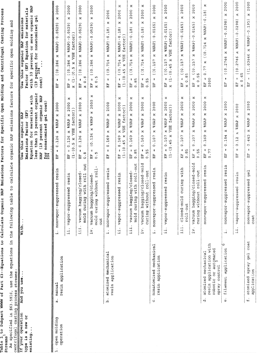
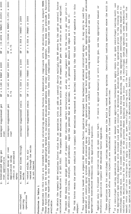 [70 FR 50129, Aug.
26, 2005]
[70 FR 50129, Aug.
26, 2005]Table 2 to Subpart WWWW of Part 63 - Compliance Dates for New and Existing Reinforced Plastic Composites Facilities
40:14.0.1.1.1.30.378.37.181 :
Table 2 to Subpart WWWW of Part 63 - Compliance Dates for New and Existing Reinforced Plastic Composites FacilitiesAs required in §§ 63.5800 and 63.5840 you must demonstrate compliance with the standards by the dates in the following table:
| If your facility is . . . | And . . . | Then you must comply by this date . . . |
|---|---|---|
| 1. An existing source | a. Is a major source on or before the publication date of this subpart | April 21, 2006. |
| 2. An existing source that is an area source | Becomes a major source after the publication date of this subpart | 3 years after becoming a major source or April 21, 2006, whichever is later. |
| 3. An existing source, and emits less than 100 tpy of organic HAP from the combination of all centrifugal casting and continuous lamination/casting operations at the time of initial compliance with this subpart | Subsequently increases its actual organic HAP emissions to 100 tpy or more from these operations, which requires that the facility must now comply with the standards in § 63.5805(b) | 3 years of the date your semi-annual compliance report indicates your facility meets or exceeds the 100 tpy threshold. |
| 4. A new source | Is a major source at startup | Upon startup or April 21, 2003, whichever is later. |
| 5. A new source | Is an area source at startup and becomes a major source | Immediately upon becoming a major source. |
| 6. A new source, and emits less than 100 tpy of organic HAP from the combination of all open molding, centrifugal casting, continuous lamination/casting, pultrusion, SMC and BMC manufacturing, and mixing operations at the time of initial compliance with this subpart | Subsequently increases its actual organic HAP emissions to 100 tpy or more from the combination of these operations, which requires that the facility must now meet the standards in § 63.5805(d) | 3 years from the date that your semi-annual compliance report indicates your facility meets or exceeds the 100 tpy threshold. |
Table 3 to Subpart WWWW of Part 63 - Organic HAP Emissions Limits for Existing Open Molding Sources, New Open Molding Sources Emitting Less Than 100 TPY of HAP, and New and Existing Centrifugal Casting and Continuous Lamination/Casting Sources that Emit Less Than 100 TPY of HAP
40:14.0.1.1.1.30.378.37.182 :
Table 3 to Subpart WWWW of Part 63 - Organic HAP Emissions Limits for Existing Open Molding Sources, New Open Molding Sources Emitting Less Than 100 TPY of HAP, and New and Existing Centrifugal Casting and Continuous Lamination/Casting Sources that Emit Less Than 100 TPY of HAPAs specified in § 63.5805, you must meet the following organic HAP emissions limits that apply to you:
| If your operation type is . . . | And you use . . . | 1 Your organic HAP emissions limit is . . . |
|---|---|---|
| 1. open molding - corrosion-resistant and/or high strength (CR/HS) | a. mechanical resin
application b. filament application c. manual resin application |
113 lb/ton. 171 lb/ton. 123 lb/ton. |
| 2. open molding - non-CR/HS | a. mechanical resin
application b. filament application c. manual resin application |
88 lb/ton. 188 lb/ton. 87 lb/ton. |
| 3. open molding - tooling | a. mechanical resin
application b. manual resin application |
254 lb/ton. 157 lb/ton. |
| 4. open molding - low-flame spread/low-smoke products | a. mechanical resin
application b. filament application c. manual resin application |
497 lb/ton. 270 lb/ton. 238 lb/ton. |
| 5. open molding - shrinkage controlled resins 2 | a. mechanical resin
application b. filament application c. manual resin application |
354 lb/ton. 215 lb/ton. 180 lb/ton. |
| 6. open molding - gel coat 3 | a. tooling gel coating b. white/off white pigmented gel coating c. all other pigmented gel coating d. CR/HS or high performance gel coat e. fire retardant gel coat f. clear production gel coat |
440 lb/ton. 267 lb/ton. 377 lb/ton. 605 lb/ton. 854 lb/ton. 522 lb/ton. |
| 7. centrifugal casting - CR/HS | a. resin application with the
mold closed, and the mold is vented during spinning and cure b. resin application with the mold closed, and the mold is not vented during spinning and cure c. resin application with the mold open, and the mold is vented during spinning and cure d. resin application with the mold open, and the mold is not vented during spinning and cure |
25 lb/ton. 4 NA - this is considered to be a closed molding operation. 25 lb/ton. 4 Use the appropriate open molding emission limit. 5 |
| 8. centrifugal casting - non-CR/HS | a. resin application with the
mold closed, and the mold is vented during spinning and cure b. resin application with the mold closed, and mold is not vented during the spinning and cure c. resin application with the mold open, and the mold is vented during spinning and cure d. resin application with the mold open, and the mold is not vented during spinning and cure |
20 lb/ton. 4 NA - this is considered to be a closed molding operation. 20 lb/ton. 4 Use the appropriate open molding emission limit. 5 |
| 9. pultrusion 6 | N/A | reduce total organic HAP emissions by at least 60 weight percent. |
| 10. continuous lamination/casting | N/A | reduce total organic HAP emissions by at least 58.5 weight percent or not exceed an organic HAP emissions limit of 15.7 lbs of organic HAP per ton of neat resin plus and neat gel coat plus. |
1 Organic HAP emissions limits for open molding and centrifugal casting are expressed as lb/ton. You must be at or below these values based on a 12-month rolling average.
2 This emission limit applies regardless of whether the shrinkage controlled resin is used as a production resin or a tooling resin.
3 If you only apply gel coat with manual application, for compliance purposes treat the gel coat as if it were applied using atomized spray guns to determine both emission limits and emission factors. If you use multiple application methods and any portion of a specific gel coat is applied using nonatomized spray, you may use the nonatomized spray gel coat equation to calculate an emission factor for the manually applied portion of that gel coat. Otherwise, use the atomized spray gel coat application equation to calculate emission factors.
4 For compliance purposes, calculate your emission factor using only the appropriate centrifugal casting equation in item 2 of Table 1 to this subpart, or a site specific emission factor for after the mold is closed as discussed in § 63.5796.
5 Calculate your emission factor using the appropriate open molding covered cure emission factor in item 1 of Table 1 to this subpart, or a site specific emission factor as discussed in § 63.5796.
6 Pultrusion machines that produce parts that meet the following criteria: 1,000 or more reinforcements or the glass equivalent of 1,000 ends of 113 yield roving or more; and have a cross sectional area of 60 square inches or more are not subject to this requirement. Their requirement is the work practice of air flow management which is described in Table 4 to this subpart.
Table 4 to Subpart WWWW of Part 63 - Work Practice Standards
40:14.0.1.1.1.30.378.37.183 :
Table 4 to Subpart WWWW of Part 63 - Work Practice StandardsAs specified in § 63.5805, you must meet the work practice standards in the following table that apply to you:
| For . . . | You must . . . |
|---|---|
| 1. A new or existing closed molding operation using compression/injection molding | Uncover, unwrap or expose only one charge per mold cycle per compression/injection molding machine. For machines with multiple molds, one charge means sufficient material to fill all molds for one cycle. For machines with robotic loaders, no more than one charge may be exposed prior to the loader. For machines fed by hoppers, sufficient material may be uncovered to fill the hopper. Hoppers must be closed when not adding materials. Materials may be uncovered to feed to slitting machines. Materials must be recovered after slitting. |
| 2. A new or existing cleaning operation | Not use cleaning solvents that contain HAP, except that styrene may be used as a cleaner in closed systems, and organic HAP containing cleaners may be used to clean cured resin from application equipment. Application equipment includes any equipment that directly contacts resin. |
| 3. A new or existing materials HAP-containing materials storage operation | Keep containers that store HAP-containing materials closed or covered except during the addition or removal of materials. Bulk HAP-containing materials storage tanks may be vented as necessary for safety. |
| 4. An existing or new SMC manufacturing operation | Close or cover the resin delivery system to the doctor box on each SMC manufacturing machine. The doctor box itself may be open. |
| 5. An existing or new SMC manufacturing operation | Use a nylon containing film to enclose SMC. |
| 6. All mixing or BMC manufacturing operations 1 | Use mixer covers with no visible gaps present in the mixer covers, except that gaps of up to 1 inch are permissible around mixer shafts and any required instrumentation. Mixers where the emissions are fully captured and routed to a 95 percent efficient control device are exempt from this requirement. |
| 7. All mixing or BMC manufacturing operations 1 | Close any mixer vents when actual mixing is occurring, except that venting is allowed during addition of materials, or as necessary prior to adding materials or opening the cover for safety. Vents routed to a 95 percent efficient control device are exempt from this requirement. |
| 8. All mixing or BMC manufacturing operations 1 | Keep the mixer covers closed while actual mixing is occurring except when adding materials or changing covers to the mixing vessels. |
| 9. A new or existing pultrusion operation manufacturing parts that meet the following criteria: 1,000 or more reinforcements or the glass equivalent of 1,000 ends of 113 yield roving or more; and have a cross sectional area of 60 square inches or more that is not subject to the 95-percent organic HAP emission reduction requirement | i. Not allow vents from the
building ventilation system, or local or portable fans to blow
directly on or across the wet-out area(s), ii. Not permit point suction of ambient air in the wet-out area(s) unless that air is directed to a control device, iii. Use devices such as deflectors, baffles, and curtains when practical to reduce air flow velocity across the wet-out area(s), iv. Direct any compressed air exhausts away from resin and wet-out area(s), v. Convey resin collected from drip-off pans or other devices to reservoirs, tanks, or sumps via covered troughs, pipes, or other covered conveyance that shields the resin from the ambient air, vi. Cover all reservoirs, tanks, sumps, or HAP-containing materials storage vessels except when they are being charged or filled, and vii. Cover or shield from ambient air resin delivery systems to the wet-out area(s) from reservoirs, tanks, or sumps where practical. |
1 Containers of 5 gallons or less may be open when active mixing is taking place, or during periods when they are in process (i.e., they are actively being used to apply resin). For polymer casting mixing operations, containers with a surface area of 500 square inches or less may be open while active mixing is taking place.
Table 5 to Subpart WWWW of Part 63 - Alternative Organic HAP Emissions Limits for Open Molding, Centrifugal Casting, and SMC Manufacturing Operations Where the Standards Are Based on a 95 Percent Reduction Requirement
40:14.0.1.1.1.30.378.37.184 :
Table 5 to Subpart WWWW of Part 63 - Alternative Organic HAP Emissions Limits for Open Molding, Centrifugal Casting, and SMC Manufacturing Operations Where the Standards Are Based on a 95 Percent Reduction RequirementAs specified in § 63.5805, as an alternative to the 95 percent organic HAP emissions reductions requirement, you may meet the appropriate organic HAP emissions limits in the following table:
| If your operation type is . . . | And you use . . . | LYour organic HAP emissions limit is a 1. . . |
|---|---|---|
| 1. Open molding - corrosion-resistant and/or high strength (CR/HS) | a. Mechanical resin application | 6 lb/ton. |
| b. Filament application | 9 lb/ton. | |
| c. Manual resin application | 7 lb/ton. | |
| 2. Open molding - non-CR/HS | a. mechanical resin application | 13 lb/ton. |
| b. Filament application | 10 lb/ton. | |
| c. Manual resin application | 5 lb/ton. | |
| 3. Open molding - tooling | a. Mechanical resin application | 13 lb/ton. |
| b. Manual resin application | 8 lb/ton. | |
| 4. Open molding - low flame spread/low smoke products | a. Mechanical resin application | 25 lb/ton. |
| b. Filament application | 14 lb/ton. | |
| c. Manual resin application | 12 lb/ton. | |
| 5. Open molding - shrinkage controlled resins | a. Mechanical resin application | 18 lb/ton. |
| b. Filament application | 11 lb/ton. | |
| c. Manual resin application | 9 lb/ton. | |
| 6. Open molding - gel coat 2 | a. Tooling gel coating | 22 lb/ton. |
| b. White/off white pigmented gel coating | 22 lb/ton. | |
| c. All other pigmented gel coating | 19 lb/ton. | |
| d. CR/HS or high performance gel coat | 31 lb/ton. | |
| e. Fire retardant gel coat | 43 lb/ton. | |
| f. Clear production gel coat | 27 lb/ton. | |
| 7. Centrifugal casting - CR/HS 3 4 | A vent system that moves heated air through the mold | 27 lb/ton. |
| 8. Centrifugal casting - non-CR/HS 3 4 | A vent system that moves heated air through the mold | 21 lb/ton. |
| 7. Centrifugal casting - CR/HS 3 4 | A vent system that moves ambient air through the mold | 2 lb/ton. |
| 8. Centrifugal casting - non-CR/HS 3 4 | A vent system that moves ambient air through the mold | 1 lb/ton. |
| 9. SMC Manufacturing | N/A | 2.4 lb/ton. |
1 Organic HAP emissions limits for open molding and centrifugal casting expressed as lb/ton are calculated using the equations shown in Table 1 to this subpart. You must be at or below these values based on a 12-month rolling average.
2 These limits are for spray application of gel coat. Manual gel coat application must be included as part of spray gel coat application for compliance purposes using the same organic HAP emissions factor equation and organic HAP emissions limit. If you only apply gel coat with manual application, treat the manually applied gel coat as if it were applied with atomized spray for compliance determinations.
3 Centrifugal casting operations where the mold is not vented during spinning and cure are considered to be closed molding and are not subject to any emissions limit. Centrifugal casting operations where the mold is not vented during spinning and cure, and the resin is applied to the open centrifugal casting mold using mechanical or manual open molding resin application techniques are considered to be open molding operations and the appropriate open molding emission limits apply.
4 Centrifugal casting operations where the mold is vented during spinning and the resin is applied to the open centrifugal casting mold using mechanical or manual open molding resin application techniques, use the appropriate centrifugal casting emission limit to determine compliance. Calculate your emission factor using the appropriate centrifugal casting emission factor in Table 1 to this subpart, or a site specific emission factor as discussed in § 63.5796.
Table 6 to Subpart WWWW of Part 63 - Basic Requirements for Performance Tests, Performance Evaluations, and Design Evaluations for New and Existing Sources Using Add-On Control Devices
40:14.0.1.1.1.30.378.37.185 :
Table 6 to Subpart WWWW of Part 63 - Basic Requirements for Performance Tests, Performance Evaluations, and Design Evaluations for New and Existing Sources Using Add-On Control DevicesAs required in § 63.5850 you must conduct performance tests, performance evaluations, and design evaluation according to the requirements in the following table:
| For . . . | You must . . . | Using . . . | According to the following requirements . . . |
|---|---|---|---|
| 1. Each enclosure used to collect and route organic HAP emissions to an add-on control device that is a PTE | Meet the requirements for a PTE | EPA method 204 of appendix M of 40 CFR part 51 | Enclosures that meet the requirements of EPA Method 204 of appendix M of 40 CFR part 51 for a PTE are assumed to have a capture efficiency of 100%. Note that the criteria that all access doors and windows that are not treated as natural draft openings shall be closed during routine operation of the process is not intended to require that these doors and windows be closed at all times. It means that doors and windows must be closed any time that you are not actually moving parts or equipment through them. Also, any styrene retained in hollow parts and liberated outside the PTE is not considered to be a violation of the EPA Method 204 criteria. |
| 2. Each enclosure used to collect and route organic HAP emissions to an add-on control device that is not a PTE | a. Determine the capture efficiency of each enclosure used to capture organic HAP emissions sent to an add-on control device | i. EPA methods 204B through E of appendix M of 40 CFR part 51, or | (1) Enclosures that do not meet the requirements for a PTE must determine the capture efficiency by constructing a temporary total enclosure according to the requirements of EPA Method 204 of appendix M of 40 CFR part 51 and measuring the mass flow rates of the organic HAP in the exhaust streams going to the atmosphere and to the control device. Test runs for EPA Methods 204B through E of appendix M of 40 CFR part 51 must be at least 3 hours. |
| ii. An alternative test method that meets the requirements in 40 CFR part 51, appendix M | (1) The alternative test method must the data quality objectives and lower confidence limit approaches for alternative capture efficiency protocols requirements contained in 40 CFR part 63 subpart KK, appendix A. | ||
| 3. Each control device used to comply with a percent reduction requirement, or an organic HAP emissions limit | Determine the control efficiency of each control device used to control organic HAP emissions | The test methods specified in § 63.5850 to this subpart | Testing and evaluation requirements are contained in 40 CFR part 63, subpart SS, and § 63.5850 to this subpart. |
| 4. Determining organic HAP emission factors for any operation | Determine the mass organic HAP emissions rate | The test methods specified in § 63.5850 to this subpart | Testing and evaluation requirements are contained in 40 CFR part 63, subpart SS, and § 63.5850 to this subpart. |
Table 7 to Subpart WWWW of Part 63 - Options Allowing Use of the Same Resin Across Different Operations That Use the Same Resin Type
40:14.0.1.1.1.30.378.37.186 :
Table 7 to Subpart WWWW of Part 63 - Options Allowing Use of the Same Resin Across Different Operations That Use the Same Resin TypeAs specified in § 63.5810(d), when electing to use the same resin(s) for multiple resin application methods, you may use any resin(s) with an organic HAP content less than or equal to the values shown in the following table, or any combination of resins whose weighted average organic HAP content based on a 12-month rolling average is less than or equal to the values shown the following table:
| If your facility has the following resin type and application method . . . | The highest resin weight is* * * percent organic HAP content, or weighted average weight percent organic HAP content, you can use for . . . | is . . . |
|---|---|---|
| 1. CR/HS resins, centrifugal casting 1 2 | a. CR/HS mechanical | 3 48.0 |
| b. CR/HS filament application | 48.0 | |
| c. CR/HS manual | 48.0 | |
| 2. CR/HS resins, nonatomized mechanical | a. CR/HS filament application | 46.4 |
| b. CR/HS manual | 46.4 | |
| 3. CR/HS resins, filament application | CR/HS manual | 42.0 |
| 4. non-CR/HS resins, filament application | a. non-CR/HS mechanical | 3 45.0 |
| b. non-CR/HS manual | 45.0 | |
| c. non-CR/HS centrifugal casting 1 2 | 45.0 | |
| 5. non-CR/HS resins, nonatomized mechanical | a. non-CR/HS manual | 38.5 |
| b. non-CR/HS centrifugal casting 1 2 | 38.5 | |
| 6. non-CR/HS resins, centrifugal casting 1 2 | non-CR/HS manual | 37.5 |
| 7. tooling resins, nonatomized mechanical | tooling manual | 91.4 |
| 8. tooling resins, manual | tooling atomized mechanical | 45.9 |
1 If the centrifugal casting operation blows heated air through the molds, then 95 percent capture and control must be used if the facility wishes to use this compliance option.
2 If the centrifugal casting molds are not vented, the facility may treat the centrifugal casting operations as if they were vented if they wish to use this compliance option.
3 Nonatomized mechanical application must be used.
Table 8 to Subpart WWWW of Part 63 - Initial Compliance With Organic HAP Emissions Limits
40:14.0.1.1.1.30.378.37.187 :
Table 8 to Subpart WWWW of Part 63 - Initial Compliance With Organic HAP Emissions LimitsAs specified in § 63.5860(a), you must demonstrate initial compliance with organic HAP emissions limits as specified in the following table:
| For . . . | That must meet the following organic HAP emissions limit . . . | You have demonstrated initial
compliance if . . . |
|---|---|---|
| 1. open molding and centrifugal casting operations | a. an organic HAP emissions limit shown in Tables 3 or 5 to this subpart, or an organic HAP content limit shown in Table 7 to this subpart | i. you have met the
appropriate organic HAP emissions limits for these operations as
calculated using the procedures in § 63.5810 on a 12-month rolling
average 1 year after the appropriate compliance date, and/or ii. you demonstrate that any individual resins or gel coats not included in (i) above, as applied, meet their applicable emission limits, or iii. you demonstrate using the appropriate values in Table 7 to this subpart that the weighted average of all resins and gel coats for each resin type and application method meet the appropriate organic HAP contents. |
| 2. open molding centrifugal casting, continuous lamination/casting, SMC and BMC manufacturing, and mixing operations | a. reduce total organic HAP emissions by at least 95 percent by weight | total organic HAP emissions, based on the results of the capture efficiency and destruction efficiency testing specified in Table 6 to this subpart, are reduced by at least 95 percent by weight. |
| 3. continuous lamination/casting operations | a. reduce total organic HAP emissions, by at least 58.5 weight percent, or | total organic HAP emissions, based on the results of the capture efficiency and destruction efficiency in Table 6 to this subpart and the calculation procedures specified in §§ 63.5865 through 63.5890, are reduced by at least 58.5 percent by weight. |
| b. not exceed an organic HAP emissions limit of 15.7 lbs of organic HAP per ton of neat resin plus and neat gel coat plus | total organic HAP emissions, based on the results of the capture efficiency and destruction efficiency testing specified in Table 6 to this subpart and the calculation procedures specified in §§ 63.5865 through 63.5890, do not exceed 15.7 lbs of organic HAP per ton of neat resin plus and neat gel coat plus. | |
| 4. continuous lamination/casting operations | a. reduce total organic HAP emissions by at least 95 weight percent or | total organic HAP emissions, based on the results of the capture efficiency and destruction efficiency testing specified in Table 6 to this subpart and the calculation procedures specified in §§ 63.5865 through 63.5890, are reduced by at least 95 percent by weight |
| b. not exceed an organic HAP emissions limit of 1.47 lbs of organic HAP per ton of neat resin plus and neat gel coat plus | total organic HAP emissions, based on the results of the capture efficiency and destruction efficiency testing specified in Table 6 and the calculation procedures specified in §§ 63.5865 through 63.5890, do not exceed 1.47 lbs of organic HAP of per ton of neat resin plus and neat gel coat plus. | |
| 5. pultrusion operations | a. reduce total organic HAP emissions by at least 60 percent by weight | i. total organic HAP
emissions, based on the results of the capture efficiency and
add-on control device destruction efficiency testing specified in
Table 6 to this subpart, are reduced by at least 60 percent by
weight, and/or ii. as part of the notification of initial compliance status, the owner/operator submits a certified statement that all pultrusion lines not controlled with an add-on control device, but for which an emission reduction is being claimed, are using direct die injection, and/or wet-area enclosures that meet the criteria of § 63.5830. |
| 6. pultrusion operations | a. reduce total organic HAP emissions by at least 95 percent by weight | i. total organic HAP emissions, based on the results of the capture efficiency and add-on control device destruction efficiency testing specified in Table 6 to this subpart, are reduced by at least 95 percent by weight. |
Table 9 to Subpart WWWW of Part 63 - Initial Compliance With Work Practice Standards
40:14.0.1.1.1.30.378.37.188 :
Table 9 to Subpart WWWW of Part 63 - Initial Compliance With Work Practice StandardsAs specified in § 63.5860(a), you must demonstrate initial compliance with work practice standards as specified in the following table:
| For . . . | That must meet the following standards . . . | You have demonstrated initial compliance if . . . |
|---|---|---|
| 1. a new or existing closed molding operation using compression/injection molding | uncover, unwrap or expose only one charge per mold cycle per compression/injection molding machine. For machines with multiple molds, one charge means sufficient material to fill all molds for one cycle. For machines with robotic loaders, no more than one charge may be exposed prior to the loader. For machines fed by hoppers, sufficient material may be uncovered to fill the hopper. Hoppers must be closed when not adding materials. Materials may be uncovered to feed to slitting machines. Materials must be recovered after slitting | the owner or operator submits a certified statement in the notice of compliance status that only one charge is uncovered, unwrapped, or exposed per mold cycle per compression/injection molding machine, or prior to the loader, hoppers are closed except when adding materials, and materials are recovered after slitting. |
| 2. a new or existing cleaning operation | not use cleaning solvents that contain HAP, except that styrene may be used in closed systems, and organic HAP containing materials may be used to clean cured resin from application equipment. Application equipment includes any equipment that directly contacts resin between storage and applying resin to the mold or reinforcement | the owner or operator submits a certified statement in the notice of compliance status that all cleaning materials, except styrene contained in closed systems, or materials used to clean cured resin from application equipment, contain no HAP. |
| 3. a new or existing materials HAP-containing materials storage operation | keep containers that store HAP-containing materials closed or covered except during the addition or removal of materials. Bulk HAP-containing materials storage tanks may be vented as necessary for safety | the owner or operator submits a certified statement in the notice of compliance status that all HAP-containing storage containers are kept closed or covered except when adding or removing materials, and that any bulk storage tanks are vented only as necessary for safety. |
| 4. an existing or new SMC manufacturing operation | close or cover the resin delivery system to the doctor box on each SMC manufacturing machine. The doctor box itself may be open | the owner or operator submits a certified statement in the notice of compliance status that the resin delivery system is closed or covered. |
| 5. an existing or new SMC manufacturing operation | use a nylon containing film to enclose SMC | the owner or operator submits a certified statement in the notice of compliance status that a nylon-containing film is used to enclose SMC. |
| 6. an existing or new mixing or BMC manufacturing operation | use mixer covers with no visible gaps present in the mixer covers, except that gaps of up to 1 inch are permissible around mixer shafts and any required instrumentation | the owner or operator submits a certified statement in the notice of compliance status that mixer covers are closed during mixing except when adding materials to the mixers, and that gaps around mixer shafts and required instrumentation are less than 1 inch. |
| 7. an existing mixing or BMC manufacturing operation | not actively vent mixers to the atmosphere while the mixing agitator is turning, except that venting is allowed during addition of materials, or as necessary prior to adding materials for safety | the owner or operator submits a certified statement in the notice of compliance status that mixers are not actively vented to the atmosphere when the agitator is turning except when adding materials or as necessary for safety. |
| 8. a new or existing mixing or BMC manufacturing operation | keep the mixer covers closed during mixing except when adding materials to the mixing vessels | the owner or operator submits a certified statement in the notice of compliance status that mixers closed except when adding materials to the mixing vessels. |
| 9. a new or existing pultrusion operation manufacturing parts that meet the following criteria: 1,000 or more reinforcements or the glass equivalent of 1,000 ends of 113 yield roving or more; and have a cross sectional area of 60 square inches or more that is not subject to the 95 percent organic HAP emission reduction requirement | i. Not allow vents from the
building ventilation system, or local or portable fans to blow
directly on or across the wet-out area(s), ii. not permit point suction of ambient air in the wet-out area(s) unless that air is directed to a control device, iii. use devices such as deflectors, baffles, and curtains when practical to reduce air flow velocity across the wet-out area(s), iv. direct any compressed air exhausts away from resin and wet-out area(s), v. convey resin collected from drip-off pans or other devices to reservoirs, tanks, or sumps via covered troughs, pipes, or other covered conveyance that shields the resin from the ambient air, vi. clover all reservoirs, tanks, sumps, or HAP-containing materials storage vessels except when they are being charged or filled, and vii. cover or shield from ambient air resin delivery systems to the wet-out area(s) from reservoirs, tanks, or sumps where practical. |
the owner or operator submits a certified statement in the notice of compliance status that they have complied with all the requirements listed in 9.i through 9.vii. |
Table 10 to Subpart WWWW of Part 63 - Data Requirements for New and Existing Continuous Lamination Lines and Continuous Casting Lines Complying With a Percent Reduction Limit on a Per Line Basis
40:14.0.1.1.1.30.378.37.189 :
Table 10 to Subpart WWWW of Part 63 - Data Requirements for New and Existing Continuous Lamination Lines and Continuous Casting Lines Complying With a Percent Reduction Limit on a Per Line BasisAs required in § 63.5865(a), in order to comply with a percent reduction limit for continuous lamination lines and continuous casting lines you must determine the data in the following table:
| For each line where the wet-out area . . . | And the oven . . . | You must determine . . . |
|---|---|---|
| 1. Has an enclosure that is not a permanent total enclosure (PTE) and the captured organic HAP emissions are controlled by an add-on control device | a. Is uncontrolled | i. Annual uncontrolled wet-out
area organic HAP emissions, ii. Annual controlled wet-out area organic HAP emissions, iii. Annual uncontrolled oven organic HAP emissions, iv. The capture efficiency of the wet-out area enclosure, |
| v. The destruction efficiency
of the add-on control device, and vi. The amount of neat resin plus and neat gel coat plus applied. |
||
| 2. Has an enclosure that is a PTE and the captured organic HAP emissions are controlled by an add-on control device | a. Is uncontrolled | i. Annual uncontrolled wet-out
area organic HAP emissions, ii. Annual controlled wet-out area organic HAP emissions, iii. Annual uncontrolled oven organic HAP emissions, iv. That the wet-out area enclosure meets the requirements of EPA Method 204 of appendix M to 40 CFR part 51 for a PTE, v. The destruction efficiency of the add-on control device, and vi. The amount of neat resin plus and neat gel coat plus applied. |
| 3. Is uncontrolled | a. Is controlled by an add-on control device | i. Annual uncontrolled wet-out
area organic HAP emissions, ii. Annual uncontrolled oven organic HAP emissions, iii. Annual controlled oven organic HAP emissions, iv. The capture efficiency of the oven, v. the destruction efficiency of the add-on control device, and vi. the amount of neat resin plus and neat gel coat plus applied. |
| 4. Has an enclosure that is not a PTE and the captured organic HAP emissions are controlled by an add-on control device | a. Is controlled by an add-on control device | i. Annual uncontrolled wet-out
area organic HAP emissions, ii. Annual controlled wet-out area organic HAP emissions, iii. Annual uncontrolled oven organic HAP emissions, iv. Annual controlled oven organic HAP emissions; v. The capture efficiency of the wet-out area enclosure, vi. Inlet organic HAP emissions to the add-on control device, vii. Outlet organic HAP emissions from the add-on control device, and viii. The amount of neat resin plus and neat gel coat plus applied. |
| 5. Has an enclosure that is a PTE and the captured organic HAP emissions are controlled by an add-on control device | a. Is controlled by an add-on control device | i. That the wet-out area
enclosure meets the requirements of EPA Method 204 of appendix M to
40 CFR part 51 for a PTE, ii. The capture efficiency of the oven, and |
| iii. The destruction efficiency of the add-on control device. |
Table 11 to Subpart WWWW of Part 63 - Data Requirements for New and Existing Continuous Lamination and Continuous Casting Lines Complying With a Percent Reduction Limit or a Lbs/Ton Limit on an Averaging Basis
40:14.0.1.1.1.30.378.37.190 :
Table 11 to Subpart WWWW of Part 63 - Data Requirements for New and Existing Continuous Lamination and Continuous Casting Lines Complying With a Percent Reduction Limit or a Lbs/Ton Limit on an Averaging BasisAs required in § 63.5865, in order to comply with a percent reduction limit or a lbs/ton limit on an averaging basis for continuous lamination lines and continuous casting lines you must determine the data in the following table:
| For each . . . | That . . . | You must determine . . . |
|---|---|---|
| 1. Wet-out area | Is uncontrolled | Annual uncontrolled wet-out area organic HAP emissions. |
| 2. Wet-out area | a. Has an enclosure that is not a PTE | i. The capture efficiency of
the enclosure, and ii. Annual organic HAP emissions that escape the enclosure. |
| 3. Wet-out area | Has an enclosure that is a PTE | That the enclosure meets the requirements of EPA Method 204 of appendix M to 40 CFR part 51 for a PTE. |
| 4. Oven | Is uncontrolled | Annual uncontrolled oven organic HAP emissions. |
| 5. Line | a. Is controlled or uncontrolled | i. The amount of neat resin
plus applied, and ii. The amount of neat gel coat plus applied. |
| 6. Add-on control device | i. Total annual inlet organic HAP emissions, and total annual outlet organic HAP emissions. |
Table 12 to Subpart WWWW of Part 63 - Data Requirements for New and Existing Continuous Lamination Lines and Continuous Casting Lines Complying With a Lbs/Ton Organic HAP Emissions Limit on a Per Line Basis
40:14.0.1.1.1.30.378.37.191 :
Table 12 to Subpart WWWW of Part 63 - Data Requirements for New and Existing Continuous Lamination Lines and Continuous Casting Lines Complying With a Lbs/Ton Organic HAP Emissions Limit on a Per Line BasisAs required in § 63.5865(b), in order to comply with a lbs/ton organic HAP emissions limit for continuous lamination lines and continuous casting lines you must determine the data in the following table:
| For each line where the wet- out area . . . | And the oven . . . | You must determine . . . |
|---|---|---|
| 1. Is uncontrolled | a. Is uncontrolled | i. Annual uncontrolled wet-out
area organic HAP emissions, ii. Annual uncontrolled oven organic HAP emissions, and iii. Annual neat resin plus and neat gel coat plus applied. |
| 2. Has an enclosure that is not a PTE and the captured organic HAP emissions are controlled by an add-on control device | a. Is uncontrolled | i. Annual uncontrolled wet-out
area organic HAP emissions, ii. Annual controlled wet-out area organic HAP emissions, iii. Annual uncontrolled oven organic HAP emissions, |
| iv. The capture efficiency of
the wet-out area enclosure, v. The destruction efficiency of the add-on control device, and vi. The amount of neat resin plus and neat gel coat plus applied. |
||
| 3. Has an enclosure that is a PTE, and the captured organic HAP emissions are controlled by an add-on control device | a. Is uncontrolled | i. Annual uncontrolled wet-out
area organic HAP emissions, ii. Annual controlled wet-out area organic HAP emissions, iii. Annual uncontrolled oven organic HAP emissions, |
| iv. That the wet-out area
enclosure meets the requirements of EPA Method 204 of appendix M to
40 CFR part 51 for a PTE, v. The destruction efficiency of the add-on control device, and vi. The amount of neat resin plus and neat gel coat plus applied. |
||
| 4. Is uncontrolled | a. Is controlled by an add-on control device | i. Annual uncontrolled wet-out
area organic HAP emissions, ii. Annual uncontrolled oven organic HAP emissions, iii. Annual controlled oven organic HAP emissions, |
| iv. The capture efficiency of
the oven, v. The destruction efficiency of the add-on control device, and vi. The amount of neat resin plus and neat gel coat plus applied. |
||
| 5. Has an enclosure that is not a PTE and the captured organic HAP emissions are controlled by an add-on control device | a. Is controlled by an add-on control device | i. Annual uncontrolled wet-out
area organic HAP emissions, ii. Annual controlled wet-out area organic HAP emissions, iii. Annual uncontrolled oven organic HAP emissions, |
| iv. Annual controlled oven
organic HAP emissions, v. The capture efficiency of the wet-out area enclosure, vi. The capture efficiency of the oven, |
||
| vii. The destruction
efficiency of the add-on control device, and viii. The amount of neat resin plus and neat gel coat plus applied. |
||
| 6. Has an enclosure that is a PTE, and the captured organic HAP emissions are controlled by add-on control device | a. Is controlled by an add-on control device | i. That the wet-out area
enclosure meets the requirements of EPA Method 204 of appendix M to
40 CFR part 51 for a PTE, ii. The capture efficiency of the oven, iii. Inlet organic HAP emissions to the an add-on control device, and |
| iv. Outlet organic HAP emissions from the add-on control device. |
Table 13 to Subpart WWWW of Part 63 - Applicability and Timing of Notifications
40:14.0.1.1.1.30.378.37.192 :
Table 13 to Subpart WWWW of Part 63 - Applicability and Timing of NotificationsAs required in § 63.5905(a), you must determine the applicable notifications and submit them by the dates shown in the following table:
| If your facility . . . | You must submit . . . | By this date . . . |
|---|---|---|
| 1. Is an existing source subject to this subpart | An Initial Notification containing the information specified in § 63.9(b)(2) | No later than the dates specified in § 63.9(b)(2). |
| 2. Is a new source subject to this subpart | The notifications specified in § 63.9(b)(4) and (5) | No later than the dates specified § 63.9(b)(4) and (5). |
| 3. Qualifies for a compliance extension as specified in § 63.9(c) | A request for a compliance extension as specified in § 63.9(c) | No later than the dates specified in § 63.6(i). |
| 4. Is complying with organic HAP emissions limit averaging provisions | A Notification of Compliance Status as specified in § 63.9(h) | No later than 1 year plus 30 days after your facility's compliance date. |
| 5. Is complying with organic HAP content limits, application equipment requirements, or organic HAP emissions limit other than organic HAP emissions limit averaging | A Notification of Compliance Status as specified in § 63.9(h) | No later than 30 calendar days after your facility's compliance date. |
| 6. Is complying by using an add-on control device | a. A notification of intent to conduct a performance test as specified in § 63.9(e) | No later than the date specified in § 63.9(e). |
| b. A notification of the date for the CMS performance evaluation as specified in § 63.9(g) | The date of submission of notification of intent to conduct a performance test. | |
| c. A Notification of Compliance Status as specified in § 63.9(h) | No later than 60 calendar days after the completion of the add-on control device performance test and CMS performance evaluation. |
Table 14 to Subpart WWWW of Part 63 - Requirements for Reports
40:14.0.1.1.1.30.378.37.193 :
Table 14 to Subpart WWWW of Part 63 - Requirements for ReportsAs required in § 63.5910(a), (b), (g), and (h), you must submit reports on the schedule shown in the following table:
| You must submit a(n) | The report must contain . . . | You must submit the report . . . |
|---|---|---|
| 1. Compliance report | a. A statement that there were no deviations during that reporting period if there were no deviations from any emission limitations (emission limit, operating limit, opacity limit, and visible emission limit) that apply to you and there were no deviations from the requirements for work practice standards in Table 4 to this subpart that apply to you. If there were no periods during which the CMS, including CEMS, and operating parameter monitoring systems, was out of control as specified in § 63.8(c)(7), the report must also contain a statement that there were no periods during which the CMS was out of control during the reporting period | Semiannually according to the requirements in § 63.5910(b). |
| b. The information in § 63.5910(d) if you have a deviation from any emission limitation (emission limit, operating limit, or work practice standard) during the reporting period. If there were periods during which the CMS, including CEMS, and operating parameter monitoring systems, was out of control, as specified in § 63.8(c)(7), the report must contain the information in § 63.5910(e) | Semiannually according to the requirements in § 63.5910(b). |
Table 15 to Subpart WWWW of Part 63 - Applicability of General Provisions (Subpart A) to Subpart WWWW of Part 63
40:14.0.1.1.1.30.378.37.194 :
Table 15 to Subpart WWWW of Part 63 - Applicability of General Provisions (Subpart A) to Subpart WWWW of Part 63As specified in § 63.5925, the parts of the General Provisions which apply to you are shown in the following table:
| The general provisions reference . . . |
That addresses . . . | And applies to subpart WWWW of part 63 . . . | Subject to the following
additional information . . . |
|---|---|---|---|
| § 63.1(a)(1) | General applicability of the general provisions | Yes | Additional terms defined in subpart WWWW of part 63, when overlap between subparts A and WWWW of this part, subpart WWWW of part 63 takes precedence. |
| § 63.1(a)(2) through (4) | General applicability of the general provisions | Yes | |
| § 63.1(a)(5) | Reserved | No | |
| § 63.1(a)(6) | General applicability of the general provisions | Yes | |
| § 63.1(a)(7) through (9) | Reserved | No | |
| § 63.1(a)(10) through (14) | General applicability of the general provisions | Yes | |
| § 63.1(b)(1) | Initial applicability determination | Yes | Subpart WWWW of part 63 clarifies the applicability in §§ 63.5780 and 63.5785. |
| § 63.1(b)(2) | Reserved | No | |
| § 63.1(b)(3) | Record of the applicability determination | Yes | |
| § 63.1(c)(1) | Applicability of this part after a relevant standard has been set under this part | Yes | Subpart WWWW of part 63 clarifies the applicability of each paragraph of subpart A to sources subject to subpart WWWW of part 63. |
| § 63.1(c)(2) | Title V operating permit requirement | Yes | All major affected sources are required to obtain a title V operating permit. Area sources are not subject to subpart WWWW of part 63. |
| § 63.1(c)(3) and (4) | Reserved | No | |
| § 63.1(c)(5) | Notification requirements for an area source that increases HAP emissions to major source levels | Yes | |
| § 63.1(c)(6) | Reclassification | Yes | |
| § 63.1(d) | Reserved | No | |
| § 63.1(e) | Applicability of permit program before a relevant standard has been set under this part | Yes | |
| § 63.2 | Definitions | Yes | Subpart WWWW of part 63 defines terms in § 63.5935. When overlap between subparts A and WWWW of part 63 occurs, you must comply with the subpart WWWW of part 63 definitions, which take precedence over the subpart A definitions. |
| § 63.3 | Units and abbreviations | Yes | Other units and abbreviations used in subpart WWWW of part 63 are defined in subpart WWWW of part 63. |
| § 63.4 | Prohibited activities and circumvention | Yes | § 63.4(a)(3) through (5) is reserved and does not apply. |
| § 63.5(a)(1) and (2) | Applicability of construction and reconstruction | Yes | Existing facilities do not become reconstructed under subpart WWWW of part 63. |
| § 63.5(b)(1) | Relevant standards for new sources upon construction | Yes | Existing facilities do not become reconstructed under subpart WWWW of part 63. |
| § 63.5(b)(2) | Reserved | No | |
| § 63.5(b)(3) | New construction/reconstruction | Yes | Existing facilities do not become reconstructed under subpart WWWW of part 63. |
| § 63.5(b)(4) | Construction/reconstruction notification | Yes | Existing facilities do not become reconstructed under subpart WWWW of part 63. |
| § 63.5(b)(5) | Reserved | No | |
| § 63.5(b)(6) | Equipment addition or process change | Yes | Existing facilities do not become reconstructed under subpart WWWW of part 63. |
| § 63.5(c) | Reserved | No | |
| § 63.5(d)(1) | General application for approval of construction or reconstruction | Yes | Existing facilities do not become reconstructed under subpart WWWW of part 63. |
| § 63.5(d)(2) | Application for approval of construction | Yes | |
| § 63.5(d)(3) | Application for approval of reconstruction | No | |
| § 63.5(d)(4) | Additional information | Yes | |
| § 63.5(e)(1) through (5) | Approval of construction or reconstruction | Yes | |
| § 63.5(f)(1) and (2) | Approval of construction or reconstruction based on prior State preconstruction review | Yes | |
| § 63.6(a)(1) | Applicability of compliance with standards and maintenance requirements | Yes | |
| § 63.6(a)(2) | Applicability of area sources that increase HAP emissions to become major sources | Yes | |
| § 63.6(b)(1) through (5) | Compliance dates for new and reconstructed sources | Yes | Subpart WWWW of part 63 clarifies compliance dates in § 63.5800. |
| § 63.6(b)(6) | Reserved | No | |
| § 63.6(b)(7) | Compliance dates for new operations or equipment that cause an area source to become a major source | Yes | New operations at an existing facility are not subject to new source standards. |
| § 63.6(c)(1) and (2) | Compliance dates for existing sources | Yes | Subpart WWWW of part 63 clarifies compliance dates in § 63.5800. |
| § 63.6(c)(3) and (4) | Reserved | No | |
| § 63.6(c)(5) | Compliance dates for existing area sources that become major | Yes | Subpart WWWW of part 63 clarifies compliance dates in § 63.5800. |
| § 63.6(d) | Reserved | No | |
| § 63.6(e)(1) | Operation and maintenance requirements | Yes | Except portions of § 63.6(e)(1)(i) and (ii) specific to conditions during startup, shutdown, or malfunction. |
| § 63.6(e)(3) | SSM plan and recordkeeping | No | |
| § 63.6(f)(1) | Compliance except during periods of startup, shutdown, and malfunction | No | Subpart WWWW of part 63 requires compliance at all times. |
| § 63.6(f)(2) and (3) | Methods for determining compliance | Yes | |
| § 63.6(g)(1) through (3) | Alternative standard | Yes | |
| § 63.6(h) | Opacity and visible emission Standards | No | Subpart WWWW of part 63 does not contain opacity or visible emission standards. |
| § 63.6(i)(1) through (14) | Compliance extensions | Yes | |
| § 63.6(i)(15) | Reserved | No | |
| § 63.6(i)(16) | Compliance extensions | Yes | |
| § 63.6(j) | Presidential compliance exemption | Yes | |
| § 63.7(a)(1) | Applicability of performance testing requirements | Yes | |
| § 63.7(a)(2) | Performance test dates | No | Subpart WWWW of part 63 initial compliance requirements are in § 63.5840. |
| § 63.7(a)(3) | CAA Section 114 authority | Yes | |
| § 63.7(b)(1) | Notification of performance test | Yes | |
| § 63.7(b)(2) | Notification rescheduled performance test | Yes | |
| § 63.7(c) | Quality assurance program, including test plan | Yes | Except that the test plan must be submitted with the notification of the performance test. |
| § 63.7(d) | Performance testing facilities | Yes | |
| § 63.7(e) | Conditions for conducting performance tests | Yes | Performance test requirements
are contained in § 63.5850. Additional requirements for conducting
performance tests for continuous lamination/casting are included in
§ 63.5870. Conditions specific to operations during periods of startup, shutdown, and malfunction in § 63.7(e)(1) do not apply. |
| § 63.7(f) | Use of alternative test method | Yes | |
| § 63.7(g) | Performance test data analysis, recordkeeping, and reporting | Yes | |
| § 63.7(h) | Waiver of performance tests | Yes | |
| § 63.8(a)(1) and (2) | Applicability of monitoring requirements | Yes | |
| § 63.8(a)(3) | Reserved | No | |
| § 63.8(a)(4) | Monitoring requirements when using flares | Yes | |
| § 63.8(b)(1) | Conduct of monitoring exceptions | Yes | |
| § 63.8(b)(2) and (3) | Multiple effluents and multiple monitoring systems | Yes | |
| § 63.8(c)(1) | Compliance with CMS operation and maintenance requirements | Yes | This section applies if you
elect to use a CMS to demonstrate continuous compliance with an
emission limit. Except references to SSM plans in § 63.8(c)(1)(i) and (iii). |
| § 63.8(c)(2) and (3) | Monitoring system installation | Yes | This section applies if you elect to use a CMS to demonstrate continuous compliance with an emission limit. |
| § 63.8(c)(4) | CMS requirements | Yes | This section applies if you elect to use a CMS to demonstrate continuous compliance with an emission limit. |
| § 63.8(c)(5) | Continuous Opacity Monitoring System (COMS) minimum procedures | No | Subpart WWWW of part 63 does not contain opacity standards. |
| § 63.8(c)(6) through (8) | CMS calibration and periods CMS is out of control | Yes | This section applies if you elect to use a CMS to demonstrate continuous compliance with an emission limit. |
| § 63.8(d)(1)-(2) | CMS quality control program, including test plan and all previous versions | Yes | This section applies if you elect to use a CMS to demonstrate continuous compliance with an emission limit. |
| § 63.8(d)(3) | CMS quality control program, including test plan and all previous versions | Yes | Except references to SSM plans in § 63.8(d)(3). |
| § 63.8(e)(1) | Performance evaluation of CMS | Yes | This section applies if you elect to use a CMS to demonstrate continuous compliance with an emission limit. |
| § 63.8(e)(2) | Notification of performance evaluation | Yes | This section applies if you elect to use a CMS to demonstrate continuous compliance with an emission limit. |
| § 63.8(e)(3) and (4) | CMS requirements/alternatives | Yes | This section applies if you elect to use a CMS to demonstrate continuous compliance with an emission limit. |
| § 63.8(e)(5)(i) | Reporting performance evaluation results | Yes | This section applies if you elect to use a CMS to demonstrate continuous compliance with an emission limit. |
| § 63.8(e)(5)(ii) | Results of COMS performance evaluation | No | Subpart WWWW of part 63 does not contain opacity standards. |
| § 63.8(f)(1) through (3) | Use of an alternative monitoring method | Yes | |
| § 63.8(f)(4) | Request to use an alternative monitoring method | Yes | |
| § 63.8(f)(5) | Approval of request to use an alternative monitoring method | Yes | |
| § 63.8(f)(6) | Request for alternative to relative accuracy test and associated records | Yes | This section applies if you elect to use a CMS to demonstrate continuous compliance with an emission limit. |
| § 63.8(g)(1) through (5) | Data reduction | Yes | |
| § 63.9(a)(1) through (4) | Notification requirements and general information | Yes | |
| § 63.9(b)(1) | Initial notification applicability | Yes | |
| § 63.9(b)(2) | Notification for affected source with initial startup before effective date of standard | Yes | |
| § 63.9(b)(3) | Reserved | No | |
| § 63.9(b)(4)(i) | Notification for a new or reconstructed major affected source with initial startup after effective date for which an application for approval of construction or reconstruction is required | Yes | |
| § 63.9(b)(4)(ii) through (iv) | Reserved | No | |
| § 63.9(b)(4)(v) | Notification for a new or reconstructed major affected source with initial startup after effective date for which an application for approval of construction or reconstruction is required | Yes | Existing facilities do not become reconstructed under subpart WWWW of part 63. |
| § 63.9(b)(5) | Notification that you are subject to this subpart for new or reconstructed affected source with initial startup after effective date and for which an application for approval of construction or reconstruction is not required | Yes | Existing facilities do not become reconstructed under subpart WWWW of part 63. |
| § 63.9(c) | Request for compliance extension | Yes | |
| § 63.9(d) | Notification of special compliance requirements for new source | Yes | |
| § 63.9(e) | Notification of performance test | Yes | |
| § 63.9(f) | Notification of opacity and visible emissions observations | No | Subpart WWWW of part 63 does not contain opacity or visible emission standards. |
| § 63.9(g)(1) | Additional notification requirements for sources using CMS | Yes | This section applies if you elect to use a CMS to demonstrate continuous compliance with an emission limit. |
| § 63.9(g)(2) | Notification of compliance with opacity emission standard | No | Subpart WWWW of part 63 does not contain opacity emission standards. |
| § 63.9(g)(3) | Notification that criterion to continue use of alternative to relative accuracy testing has been exceeded | Yes | This section applies if you elect to use a CMS to demonstrate continuous compliance with an emission limit. |
| § 63.9(h)(1) through (3) | Notification of compliance status | Yes | |
| § 63.9(h)(4) | Reserved | No | |
| § 63.9(h)(5) and (6) | Notification of compliance status | Yes | |
| § 63.9(i) | Adjustment of submittal deadlines | Yes | |
| § 63.9(j) | Change in information provided | Yes | |
| § 63.9(k) | Electronic reporting procedures | Yes | Only as specified in § 63.9(j). |
| § 63.10(a) | Applicability of recordkeeping and reporting | Yes | |
| § 63.10(b)(1) | Records retention | Yes | |
| § 63.10(b)(2)(i) through (v) | Records related to startup, shutdown, and malfunction | No | |
| § 63.10(b)(2)(vi) through (xi) | CMS records, data on performance tests, CMS performance evaluations, measurements necessary to determine conditions of performance tests, and performance evaluations | Yes | |
| § 63.10(b)(2)(xii) | Record of waiver of recordkeeping and reporting | Yes | |
| § 63.10(b)(2)(xiii) | Record for alternative to the relative accuracy test | Yes | |
| § 63.10(b)(2)(xiv) | Records supporting initial notification and notification of compliance status | Yes | |
| § 63.10(b)(3) | Records for applicability determinations | Yes | |
| § 63.10(c)(1) | CMS records | Yes | This section applies if you elect to use a CMS to demonstrate continuous compliance with an emission limit. |
| § 63.10(c)(2) through (4) | Reserved | No | |
| § 63.10(c)(5) through (8) | CMS records | Yes | This section applies if you elect to use a CMS to demonstrate continuous compliance with an emission limit. |
| § 63.10(c)(9) | Reserved | No | |
| § 63.10(c)(10) through (14) | CMS records | Yes | This section applies if you elect to use a CMS to demonstrate continuous compliance with an emission limit. |
| § 63.10(c)(15) | CMS records | No | |
| § 63.10(d)(1) | General reporting requirements | Yes | |
| § 63.10(d)(2) | Report of performance test results | Yes | |
| § 63.10(d)(3) | Reporting results of opacity or visible emission observations | No | Subpart WWWW of part 63 does not contain opacity or visible emission standards. |
| § 63.10(d)(4) | Progress reports as part of extension of compliance | Yes | |
| § 63.10(d)(5) | Startup, shutdown, and malfunction reports | No | |
| § 63.10(e)(1) through (3) | Additional reporting requirements for CMS | Yes | This section applies if you have an add-on control device and elect to use a CEM to demonstrate continuous compliance with an emission limit. |
| § 63.10(e)(4) | Reporting COMS data | No | Subpart WWWW of part 63 does not contain opacity standards. |
| § 63.10(f) | Waiver for recordkeeping or reporting | Yes | |
| § 63.11 | Control device requirements | Yes | Only applies if you elect to use a flare as a control device. |
| § 63.12 | State authority and delegations | Yes | |
| § 63.13 | Addresses of state air pollution control agencies and EPA Regional offices | Yes | |
| § 63.14 | Incorporations by reference | Yes | |
| § 63.15 | Availability of information and confidentiality | Yes |
Appendix A to Subpart WWWW of Part 63 - Test Method for Determining Vapor Suppressant Effectiveness
40:14.0.1.1.1.30.378.37.195 : Appendix A
Appendix A to Subpart WWWW of Part 63 - Test Method for Determining Vapor Suppressant Effectiveness 1. Scope and Application1.1 Applicability. If a facility is using vapor suppressants to reduce hazardous air pollutant (HAP) emissions, the organic HAP emission factor equations in Table 1 to this subpart require that the vapor suppressant effectiveness factor be determined. The vapor suppressant effectiveness factor is then used as one of the inputs into the appropriate organic HAP emission factor equation. The vapor suppressant effectiveness factor test is not intended to quantify overall volatile emissions from a resin, nor to be used as a stand-alone test for emissions determination. This test is designed to evaluate the performance of film forming vapor suppressant resin additives. The results of this test are used only in combination with the organic HAP emissions factor equations in Table 1 to this subpart to generate emission factors.
1.1.1 The open molding process consists of application of resin and reinforcements to the mold surface, followed by a manual rollout process to consolidate the laminate, and the curing stage where the laminate surface is not disturbed. Emission studies have shown that approximately 50 percent to 55 percent of the emissions occur while the resin is being applied to the mold. Vapor suppressants have little effect during this portion of the lamination process, but can have a significant effect during the curing stage. Therefore, if a suppressant is 100 percent effective, the overall emissions from the process would be reduced by 45 percent to 50 percent, representing the emissions generated during the curing stage. In actual practice, vapor suppressant effectiveness will be less than 100 percent and the test results determine the specific effectiveness in terms of the vapor suppressant effectiveness factor. This factor represents the effectiveness of a specific combination of suppressant additive and resin formulation.
1.1.2 A resin manufacturer may supply a molder with a vapor-suppressed resin, and employ this test to provide the molder with the vapor suppressant effectiveness factor for that combination of resin and vapor suppressant. The factor qualifies the effectiveness of the vapor suppressant when the resin is tested in the specific formulation supplied to the molder. The addition of fillers or other diluents by the molder may impact the effectiveness of the vapor suppressant. The formulation, including resin/glass ratio and filler content, used in the test should be similar to the formulation to be used in production. The premise of this method is to compare laminate samples made with vapor suppressant additive and made without the additive. The difference in emissions between the two yields the vapor suppressant effectiveness factor.
1.1.3 The method uses a mass balance determination to establish the relative loss of the volatile component from unsaturated polyester or vinyl ester resins, with and without vapor suppressant additives. The effectiveness of a specific vapor suppressant and resin mixture is determined by comparing the relative volatile weight losses from vapor suppressed and non-suppressed resins. The volatile species are not separately analyzed. While the species contained in the volatile component are not determined, an extended listing of potential monomer that may be contained in unsaturated polyester or vinyl ester resins is provided in Table 1.1. However, most polyester and vinyl ester resin formulations presently used by the composites industry only contain styrene monomer.
Table 1.1 - List of Monomers Potentially Present in Unsaturated Polyester/Vinyl Ester Resins
| Monomer | CAS No. |
|---|---|
| Styrene | 100-42-5. |
| Vinyl toluene | 25013-15-4. |
| Methyl methacrylate | 80-62-6. |
| Alpha methyl styrene | 98-83-9. |
| Para methyl styrene | Vinyl toluene isomer. |
| Chlorostyrene | 1331-28-8. |
| Diallyl phthalate | 131-17-9. |
| Other volatile monomers | Various. |
2.1 Differences in specific resin and suppressant additive chemistry affect the performance of a vapor suppressant. The purpose of this method is to quantify the effectiveness of a specific combination of vapor suppressant and unsaturated polyester or vinyl ester resin as they are to be used in production. This comparative test quantifies the loss of volatiles from a fiberglass reinforced laminate during the roll-out and curing emission phases, for resins formulated with and without a suppressant additive. A criterion for this method is the testing of a non-vapor suppressed resin system and testing the same resin with a vapor suppressant. The two resins are as identical as possible with the exception of the addition of the suppressant to one. The exact formulation used for the test will be determined by the in-use production requirements. Each formulation of resin, glass, fillers, and additives is developed to meet particular customer and or performance specifications.
2.2 The result of this test is used as an input factor in the organic HAP emissions factor equations in Table 1 to this subpart, which allows these equations to predict emissions from a specific combination of resin and suppressant. This test does not provide an emission rate for the entire lamination process.
3. Definitions and Acronyms3.1 Definitions
3.1.1 Vapor suppressant. An additive that inhibits the evaporation of volatile components in unsaturated polyester or vinyl ester resins.
3.1.2 Unsaturated polyester resin. A thermosetting resin commonly used in composites molding.
3.1.3 Unsaturated vinyl ester resin. A thermosetting resin used in composites molding for corrosion resistant and high performance applications.
3.1.4 Laminate. A combination of fiber reinforcement and a thermoset resin.
3.1.5 Chopped strand mat. Glass fiber reinforcement with random fiber orientation.
3.1.6 Initiator. A curing agent added to an unsaturated polyester or vinyl ester resin.
3.1.7 Resin application roller. A tool used to saturate and compact a wet laminate.
3.1.8 Gel time. The time from the addition of initiator to a resin to the state of resin gelation.
3.1.9 Filled resin system. A resin, which includes the addition of inert organic or inorganic materials to modify the resin properties, extend the volume and to lower the cost. Fillers include, but are not limited to; mineral particulates; microspheres; or organic particulates. This test is not intended to be used to determine the vapor suppressant effectiveness of a filler.
3.1.10 Material safety data sheet. Data supplied by the manufacturer of a chemical product, listing hazardous chemical components, safety precautions, and required personal protection equipment for a specific product.
3.1.11 Tare(ed). Reset a balance to zero after a container or object is placed on the balance; that is to subtract the weight of a container or object from the balance reading so as to weigh only the material placed in the container or on the object.
3.1.12 Percent glass. The specified glass fiber weight content in a laminate. It is usually determined by engineering requirements for the laminate.
3.2 Acronyms:
3.2.1 VS - vapor suppressed or vapor suppressant.
3.2.2 NVS - non-vapor suppressed.
3.2.3 VSE - vapor suppressant effectiveness.
3.2.4 VSE Factor - vapor suppressant effectiveness, factor used in the equations in Table 1 to this subpart.
3.2.5 CSM - chopped strand mat.
3.2.6 MSDS - material safety data sheet.
4. InterferencesThere are no identified interferences which affect the results of this test.
5. SafetyStandard laboratory safety procedures should be used when conducting this test. Refer to specific MSDS for handling precautions.
6. Equipment and Supplies Note:Mention of trade names or specific products or suppliers does not constitute an endorsement by the Environmental Protection Agency.
6.1 Required Equipment.
6.1.1 Balance enclosure. 1
6.1.2 Two (2) laboratory balances - accurate to ±0.01g. 2
6.1.3 Stop watch or balance data recording output to data logger with accuracy ±1 second. 3
6.1.4 Thermometer - accurate to ±2.0 °F(±1.0 °C). 4
6.1.5 A lipped pan large enough to hold the cut glass without coming into contact with the vertical sides, e.g. a pizza pan. 5
6.1.6 Mylar film sufficient to cover the bottom of the pan. 6
6.1.7 Tape to keep the Mylar from shifting in the bottom of the pan. 7
6.1.8 Plastic tri-corner beakers of equivalent - 250 ml to 400 ml capacity. 8
6.1.9 Eye dropper or pipette. 9
6.1.10 Disposable resin application roller, 3/16″- 3/4″ diameter × 3″-6″ roller length. 10
6.1.11 Hygrometer or psychrometer 11 accurate to ±5 percent
6.1.12 Insulating board, (Teflon, cardboard, foam board etc.) to prevent the balance from becoming a heat sink. 12
6.2 Optional Equipment.
6.2.1 Laboratory balance - accurate to ±.01g with digital output, such as an RS-232 bi-directional interface 13 for use with automatic data recording devices.
6.2.2 Computer with recording software configured to link to balance digital output. Must be programmed to record data at the minimum intervals required for manual data acquisition.
6.3 Supplies.
6.3.1 Chopped strand mat - 1.5 oz/ft. 2 14
7. Reagents and Standards7.1 Initiator. The initiator type, brand, and concentration will be specified by resin manufacturer, or as required by production operation.
7.2 Polyester or vinyl ester resin.
7.3 Vapor suppressant additive.
8. Sample Collection, Preservation, and StorageThis test method involves the immediate recording of data during the roll out and curing phases of the lamination process during each test run. Samples are neither collected, preserved, nor stored.
9. Quality ControlCareful attention to the prescribed test procedure, routing equipment calibration, and replicate testing are the quality control activities for this test method. Refer to the procedures in section 11. A minimum of six test runs of a resin system without a suppressant and six test runs of the same resin with a suppressant shall be performed for each resin and suppressant test combination.
10. Calibration and Standardization10.1 The laboratory balances, stopwatch, hygrometer and thermometer shall be maintained in a state of calibration prior to testing and thereafter on a scheduled basis as determined by the testing laboratory. This shall be accomplished by using certified calibration standards.
10.2 Calibration records shall be maintained for a period of 3 years.
11. Test Procedure11.1 Test Set-up.
11.1.1 The laboratory balance is located in an enclosure to prevent fluctuations in balance readings due to localized air movement. The front of enclosure is open to permit work activity, but positioned so that local airflow will not effect balance readings. The ambient temperature is determined by suspending the thermometer at a point inside the enclosure.
11.1.2 The bottom of the aluminum pan is covered with the Mylar film. The film is held in position with tape or by friction between the pan and the film.
11.1.3 The resin and pan are brought to room temperature. This test temperature must be between 70 °F and 80 °F. The testing temperature cannot vary more than ±2 °F during the measurement of test runs. Temperature shall be recorded at the same time weight is recorded on suppressed and non-suppressed test data sheets, shown in Table 17.1.
11.1.4 The relative humidity may not change more than ±15 percent during the test runs. This is determined by recording the relative humidity in the vicinity of the test chamber at the beginning and end of an individual test run. This data is recorded on the test data sheets shown in Table 17.1.
11.1.5 Two plies of nominal 1.5 oz/ft 2 chopped strand mat (CSM) are cut into a square or rectangle with the minimum surface area of 60 square inches (i.e. a square with a side dimension of 7.75 inches).
11.1.6 The appropriate resin application roller is readily available.
11.2 Resin Gel Time/Initiator Percentage
11.2.1 Previous testing has indicated that resin gel time influences the emissions from composite production. The testing indicated that longer the gel times led to higher emissions. There are a number of factors that influence gel time including initiator type, initiator brand, initiator level, temperature and resin additives. Under actual usage conditions a molder will adjust the initiator to meet a gel time requirement. In this test procedure, the vapor suppressed and non-vapor suppressed resin systems will be adjusted to the same gel time by selecting the appropriate initiator level for each.
11.2.2 All test runs within a test will be processed in a manner that produces the same resin gel time ±2 minutes. To facilitate the resin mixing procedure, master batches of resin and resin plus vapor suppressant of resin are prepared. These resin master batches will have all of the required ingredients except initiator; this includes filler for filled systems. The gel times for the tests are conducted using the master batch and adjustments to meet gel time requirements shall be made to the master batch before emission testing is conducted. Test temperatures must be maintained within the required range, during gel time testing. Further gel time testing is not required after the non-vapor suppressed and vapor suppressed master batches are established with gel times within ±2 minutes. A sufficient quantity of each resin should be prepared to allow for additional test specimens in the event one or more test fails to meet the data acceptance criteria discussed in Section 11.5 and shown in Table 17.2.
11.2.3 The specific brand of initiator and the nominal percentage level recommended by the resin manufacturer will be indicated on the resin certificate of analysis 15; or, if a unique gel time is required in a production laminate, initiator brand and percentage will be determined by that specific requirement.
11.2.4 Examples:
11.2.4.1 The resin for a test run is specified as having a 15-minute cup gel time at 77 °F using Brand X initiator at 1.5 percent by weight. The non-suppressed control resin has a 15-minute gel time. The suppressed resin has a gel time of 17-minutes. An initiator level of 1.5 percent would be selected for the both the non-suppressed and the suppressed test samples.
11.2.4.2 Based on a specific production requirement, a resin is processed in production using 2.25 percent of Brand Y initiator, which produces a 20-minute gel time. This initiator at level of 2.25 percent produces a 20 minute gel time for the non-suppressed control resin, but yields a 25-minute gel time for the suppressed resin sample. The suppressed resin is retested at 2.50 percent initiator and produces a 21-minute gel time. The initiator levels of 2.25 percent and 2.50 percent respectively would yield gel times within ±2 minutes.
11.3 Test Run Procedure for Unfilled Resin (see the data sheet shown in Table 17.1).
11.3.1 The insulating board is placed on the balance.
11.3.2 The aluminum pan with attached Mylar film is placed on the balance, and the balance is tared (weight reading set to zero with the plate on the balance.)
11.3.3 Place two plies of 1.5 oz. CSM on the balance and record the weight (glass weight).
11.3.4 The resin beaker and stirring rod are put on the second balance and tared.
11.3.5 The required resin weight and initiator weight are calculated (refer to calculation formulas in 12.2).
11.3.6 The disposable resin application roller is placed on the edge of the plate.
11.3.7 The balance is tared, with the aluminum pan, Mylar film, glass mat, and resin application roller on the balance pan.
11.3.8 Resin is weighed into a beaker, as calculated, using the second balance. The mixing stick should be tared with the beaker weight.
11.3.9 Initiator is weighed into the resin, as calculated, using an eyedropper or a pipette, and the combination is mixed.
11.3.10 Initiated resin is poured on chopped strand mat in a pe-determined pattern (see Figure 11.6).
11.3.11 A stopwatch is started from zero.
11.3.12 The initial laminate weight is recorded.
11.3.13 The plate is removed from balance to enable roll-out of the laminate.
11.3.14 The wet laminate is rolled with the resin application roller to completely distribute the resin, saturate the chopped strand mat, and eliminate air voids. Roll-out time should be in the range of 2 to 3 16 minutes and vary less than ±10 percent of the average time required for the complete set of six suppressed and six non-suppressed runs.
11.3.15 Record the rollout end time (time from start to completion of rollout).
11.3.16 Place the resin application roller on the edge of the plate when rollout is completed.
11.3.17 Place the plate back on the balance pan. Immediately record the weight.
11.3.18 For the first test in a series of six tests, weight is recorded every 5-minute interval (suppressed and non-suppressed). The end of the test occurs when three consecutive equal weights are recorded or a weight gain is observed (the last weight before the increased weight is the end of test weight). For the remaining five tests in the series, after the initial weights are taken, the next weight is recorded 30 minutes before the end of the test, as suggested by the results from the first test. It is likely that the time to reach the end point of a suppressed resin test will be shorter than the time required to complete a non-suppressed test. Therefore, the time to start taking data manually may be different for suppressed and non-suppressed resins.
11.4 Test Run Procedures for Filled Resin Systems 17 Note that the procedure for filled systems differs from the procedure for unfilled systems. With filled systems, resin is applied to one ply of the CSM and the second ply is placed on top of the resin.
11.4.1 The insulating board is placed on the balance.
11.4.2 The aluminum pan with attached Mylar film is placed on the balance, and the balance is tared (weight reading set to zero with the plate on the balance.)
11.4.3 Place two plies of 1.5 oz. CSM on the balance and record the weight (glass weight).
11.4.4 Remove the top ply of fiberglass and record its weight (weight of 1st layer of glass).
11.4.5 The required resin weight and initiator weight are calculated (refer to calculation formulas in 12.2). Calculate the weight of filled resin and initiator based on the 2 layers of fiberglass.
11.4.6 The resin beaker and stirring rod are put on the second balance and tared.
11.4.7 A disposable resin application roller is placed on the edge of the plate.
11.4.8 The balance is tared, with the aluminum pan, Mylar film, glass mat, and resin application roller on the balance pan.
11.4.9 Resin is weighed into the beaker, as calculated, using the second balance. The mixing stick should be tared with the beaker weight.
11.4.10 Initiator is weighed into the resin, as calculated, using an eyedropper or a pipette, and the combination is mixed.
11.4.11 Initiated resin is poured on the single ply of CSM in a pre-determined pattern. Refer to Figure 11.6.
11.4.12 A stopwatch is started from zero.
11.4.13 Record the weight of the resin ans single ply of CSM (L1). The initial laminate weight equals L1 plus the weight of second glass layer.
11.4.14 Replace the second layer of fiberglass.
11.4.15 Remove the plate from the balance to allow roll-out of the laminate.
11.4.16 Roll the wet laminate with the resin application roller to completely distribute the resin, saturate the chopped strand mat, and eliminate air voids. Roll-out time should be in the range of 2 to 3 16 minutes and vary less than ±10 percent of the average time required for the complete set of six suppressed and six non-suppressed runs.
11.4.17 Record the roll-out end time (time from start to completion of rollout).
11.4.18 Place the resin application roller on the edge of the plate when rollout is completed.
11.4.19 Place the plate back on the balance pan. The initial weight is recorded immediately.
11.4.20 For the first test run in a series of six, weight is recorded at every 5-minute interval (suppressed and non-suppressed). The end of the test occurs when three consecutive equal weights are recorded or a weight gain is observed (the last weight before the increased weight is the end of test weight). For the remaining five tests in the series, after the initial weights are taken, the next weight is recorded 30 minutes before the end of the test, as suggested by the results from the first test. It is likely that the time to reach the end point of a suppressed resin test will be shorter than the time required to complete a non-suppressed test. Therefore, the time to start taking data manually may be different for suppressed and non-suppressed resins.
11.5 Data Acceptance Criteria:
11.5.1 A test set is designed as twelve individual test runs using the same resin, initiator, and gel time, six of the test runs use the resin non-vapor suppressed and the other six use it vapor suppressed.
11.5.2 If a test run falls outside any of the time, temperature, weight or humidity variation requirements, it must be discarded and run again.
11.5.3 The laminate roll out time for each individual test run must vary less than ±10 percent of the average time required for the complete set of six suppressed and six non-suppressed runs.
11.5.4 Test temperature for each test run must be maintained within ±2 °F and the average must be between 70° and 80 °F. Refer to 11.1.3.
11.5.5 The difference in the amount of resin for each run must be within ±10 percent of the average weight for the complete set of six suppressed and six non-suppressed runs.
11.5.6 The relative humidity from each test run must be within ±15 percent of the average humidity for the complete set of six suppressed and six non-suppressed tests. Refer to 11.1.4
11.5.7 The glass content for each test set must be within ±10 percent of the average resin-to-/glass ratio for the complete set of six suppressed and six non-suppressed runs. Refer to 12.2).
11.5.8 The filler content for each test of a test set must be within ±5 percent of the average filler content for the complete set of six suppressed and six non-suppressed runs. Refer to 12.2.
11.6 Resin Application Pour Pattern:
11.6.1 To facilitate the distribution of resin across the chopped strand mat, and to provide consistency from test to test, a uniform pour pattern should be used. A typical pour pattern is shown below:
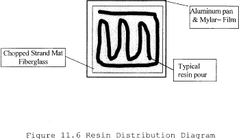
11.6.2 The resin is to be evenly distributed across the entire surface of the chopped strand mat using the resin application roller to achieve a wet look across the surface of the laminate. Pushing excess resin off the reinforcement and onto the Mylar sheet should be avoided. No resin is to be pushed more than 1/2 inch beyond the edge of the glass mat. If excess resin is pushed further from the glass mat, it will void the test run. As part of this process, typical visible air voids are to be eliminated by the rollout process. If the pour pattern is different from the above, it must be recorded and attached to test data sheet 17.1.
12. Data Analysis and Calculations12.1 Data Analysis:
This test method requires a simple mass balance calculation, no special data analysis is necessary.
12.2 Calculations:
12.2.1 The target glass content (percent) for unfilled resin systems is determined from the specific production parameters being evaluated. In absence of any specific production requirements the target may be set at the tester's discretion.
12.2.2 Glass content determination (expressed as a per cent):
% Glass = Glass wt(g)/(Glass wt(g) + Resin weight (g))12.2.3 Weight of resin required:
Resin weight required = (Glass wt (g)/% glass) - Glass wt (g)
12.2.4 Filled resin formulation determination for filled resin systems (e.g. >30 percent filler by weight for a particulate filler, or >1 percent by weight for a lightweight filler, such as hollow microspheres):
% Resin content = resin weight(g)/(resin weight(g) + glass weight(g) + filler weight(g)) % Glass content = glass weight(g)/(resin weight(g) + glass weight(g) + filler weight(g)) Filler content = filler weight(g)/(resin weight(g) + glass weight(g) + filler weight(g))12.2.5 Initiator weight determination:
Initiator weight (g) = Resin weight(g) × Initiator %12.2.6 Emission weight loss determination:
Emissions weight loss (g) = Initial resin weight (g)−Final resin weight (g)
12.2.7 % Emission weight loss:
% Emission Weight Loss = (Emission weight loss (g) Initial resin weight (g) × 10012.2.8 Average % Emission Weight Loss (assuming six test runs):
12.2.9 VSE Factor calculation:
VSE Factor = 1 −(Average % VS Emission Weight Loss/Average NVS Emission Weight Loss)Table 12.1 - Example Calculation
| Test # | % VS weight loss |
% NVS weight loss |
|---|---|---|
| 1 | 6.87 | 10.86 |
| 2 | 6.76 | 11.23 |
| 3 | 5.80 | 12.02 |
| 4 | 5.34 | 11.70 |
| 5 | 6.11 | 11.91 |
| 6 | 6.61 | 10.63 |
| Average Weight Loss | 6.25 | 11.39 |
| VSE Factor | 0.4 |
VSE Factor = 0.45
VSE Factor is used as input into the appropriate equation in Table 1 to this subpart.
Example from Table 1 to this subpart:
Manual Resin Application, 35 percent HAP resin, VSE Factor of 0.45 HAP Emissions with vapor suppresants = ((0.286 × %HAP)−0.0529) × 2000 × (1-(0.5 × VSE factor)) HAP Emissions with vapor suppresants = ((0.286 × .35)−0.0529) × 2000 × (1−(0.5 × .45)) HAP Emissions with vapor suppresants = 73 pounds of HAP emissions per ton of resin. 13. Method Performance13.1 Bias:
The bias of this test method has not been determined.
13.2 Precision Testing
13.2.1 Subsequent to the initial development of this test protocol by the Composites Fabricators Association, a series of tests were conducted in three different laboratory facilities. The purpose of this round robin testing was to verify the precision of the test method in various laboratories. Each laboratory received a sample of an orthophthalic polyester resin from the same production batch, containing 48 per cent styrene by weight. Each testing site was also provided with the same vapor suppressant additive. The suppressant manufacturer specified the percentage level of suppressant additive. The resin manufacturer specified the type and level of initiator required to produce a 20 minute gel time. The target glass content was 30 percent by weight.
13.2.2 Each laboratory independently conducted the VSE test according to this method. A summary of the results is included in Table 13.1.
Table 13.1 - Round Robin Testing Results
| Test Lab 1 | Test Lab 2 | Test Lab 3 | ||||
|---|---|---|---|---|---|---|
| NVS | VS | NVS | S | NVS | VS | |
| Average percent WT Loss | 4.24 | 1.15 | 4.69 | 1.84 | 5.73 | 1.61 |
| Standard Deviation | 0.095 | 0.060 | 0.002 | 0.002 | 0.020 | 0.003 |
| VSE Factor | 0.730 | 0.607 | 0.720 | |||
13.3 Comparison to EPA Reference Methods This test has no corresponding EPA reference method.
14. Pollution PreventionThe sample size used in this method produces a negligible emission of HAP, and has an insignificant impact upon the atmosphere.
15. Waste ManagementThe spent and waste materials generated during this test are disposed according to required facility procedures, and waste management recommendations on the corresponding material safety data sheets.
16. References and footnotes16.1 Footnotes:
1 Balance Enclosure - The purpose of the balance enclosure is to prevent localized airflow from adversely affecting the laboratory balance. The enclosure may be a simple three-sided box with a top and an open face. The configuration of the enclosure is secondary to the purpose of providing a stable and steady balance reading, free from the effects of airflow, for accurate measurements. The enclosure can be fabricated locally. A typical enclosure is shown in Figure 17.1.
2 Laboratory Balance - Ohaus Precision Standard Series P/N TS400D or equivalent - Paul N. Gardner Co. 316 NE 1st St. Pompano Beach, FL 33060 or other suppliers.
3 Stop Watch - Local supply.
4 Thermometer - Mercury thermometer - ASTM No. 21C or equivalent; Digital thermometer - P/N TH-33033 or equivalent - Paul N. Gardner Co. 316 NE 1st St. Pompano Beach, FL 33060 or other suppliers.
5 Aluminum Pan - Local supply.
6 Mylar - Local supply.
7 Double Sided Tape - 3M Double Stick Tape or equivalent, local supply.
8 Laboratory Beakers - 250 to 400ml capacity - Local laboratory supply.
9 Eye Dropper or Pipette - Local laboratory supply.
10 Disposable Resin Application Roller Source - Wire Handle Roller P/N 205-050-300 or Plastic Handle Roller P/N 215-050-300 or equivalent; ES Manufacturing Inc., 2500 26st Ave. North, St. Petersburg, FL 33713, www.esmfg.com, or other source. Refer to Figure 17.3.
11 Hygrometer or Psychrometer - Model# THWD-1, or equivalent - Part # 975765 by Amprobe Instrument, 630 Merrick Road, P.O. Box 329, Lynbrook, NY 11563, 516-593-5600
12 Insulating Board (Teflon, cardboard, foam board etc.) - Local supply.
13 Laboratory Balance With Digital Output - Ohaus Precision Standard Series P/N TS120S or equivalent - Paul N. Gardner Co. 316 NE 1st St. Pompano Beach, FL 33060 or other suppliers.
14 Chopped Strand Mat - 1.5 oz/ft 2 Sources: Owens Corning Fiberglas - Fiberglas M-723; PPG Industries - ABM HTX; Vetrotex America - M-127 or equivalent.
15 Certificate of Analysis: Resin gel time, as recorded on the resin certificate of analysis, is measured using a laboratory standard gel time procedure. This procedure typically uses a 100 gram cup sample at 77 °F (25 °C), a specific type of initiator and a specified percentage.
16 Roll-out times may vary with resin viscosity or resin additive. The important aspect of this step is to produce the same roll-out time for both the suppressed and non-suppressed samples.
17 While this test can be used with filled resin systems, the test is not designed to determine the effect of the filler on emissions, but rather to measure the effect of the suppressant additive in the resin system. When evaluating a filled system both the non-vapor suppressed and vapor suppressed samples should be formulated with the same type and level of filler.
16.2 References
1. Phase 1 - Baseline Study Hand Lay-up, CFA, 1996
2. CFA Vapor Suppressant Effectiveness Test Development, 4/3/98, correspondence with Dr. Madeleine Strum, EPA, OAQPS
3. CFA Vapor Suppressant Effectiveness Screening Tests, 4/4/98
4. Styrene Suppressant Systems Study, Reichhold Chemical, 11/30/98
5. Evaluation of the CFA's New Proposed Vapor Suppressant Effectiveness Test, Technical Service Request #: ED-01-98, BYK Chemie, 6/3/98
6. Second Evaluation of the CFA's New Proposed Vapor Suppressant Effectiveness Test, Technical Service Request #: ED-02-98, BYK Chemie, 1/26/99
17. Data Sheets and Figures17.1 This data sheet, or a similar data sheet, is used to record the test data for filled, unfilled, suppressed and non-suppressed tests. If additional time is required, the data sheet may be extended.
17.2 Data Acceptance Criteria Worksheet:
The following worksheet is used to determine the quality of collected data (i.e. insure the data collected all meets acceptance criteria)
Table 17.2 - Data Acceptance Criteria Worksheet
| Test No. | Temperature | Laminate roll out time, min | Relative humidity, % | Resin weight, (g) | Glass content, % | Resin distribution | Meets criteria Y/N | |||
|---|---|---|---|---|---|---|---|---|---|---|
| Min | Max | Delta | Initial | Final | ||||||
| 1 | ||||||||||
| 2 | ||||||||||
| 3 | ||||||||||
| 4 | ||||||||||
| 5 | ||||||||||
| 6 | ||||||||||
| 7 | ||||||||||
| 8 | ||||||||||
| 9 | ||||||||||
| 10 | ||||||||||
| 11 | ||||||||||
| 12 | ||||||||||
| Average | ||||||||||
| Criteria | ±2 °F | ±10% of Average | ±15 of Average | ±15 of Average | ±10% of Avg. | ±10% of Avg. | < 1/2 inch off mat | All Y | ||
17.3 VSE Factor Calculation
Table 17.3 - Calculations Worksheet
| Vapor suppressed | Non-vapor suppressed | ||
|---|---|---|---|
| Test # | % Weight loss | Test # | % Weight loss |
| Average Weight Loss | |||
| VSE Factor | |||
VSE Factor = 1 - (% Average Weight Loss VS/ % Average Weight LossNVS)
17.4 Figures
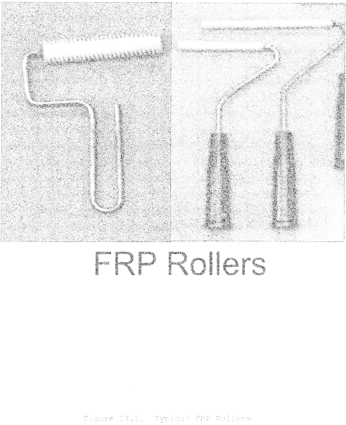
Table 1 to Subpart XXXX of Part 63 - Emission Limits for Tire Production Affected Sources
40:14.0.1.1.1.31.392.37.196 :
Table 1 to Subpart XXXX of Part 63 - Emission Limits for Tire Production Affected SourcesAs stated in § 63.5984, you must comply with the emission limits for each new, reconstructed, or existing tire production affected source in the following table:
| For each . . . | You must meet the following emission limits. |
|---|---|
| 1. Option 1 - HAP constituent option | a. Emissions of each HAP in Table 16 to this subpart must not exceed 1,000 grams HAP per megagram (2 pounds per ton) of total cements and solvents used at the tire production affected source, and b. Emissions of each HAP not in Table 16 to this subpart must not exceed 10,000 grams HAP per megagram (20 pounds per ton) of total cements and solvents used at the tire production affected source. |
| 2. Option 2 - production-based option | Emissions of HAP must not exceed 0.024 grams per megagram (0.00005 pounds per ton) of rubber used at the tire production affected source. |
Table 2 to Subpart XXXX of Part 63 - Emission Limits for Tire Cord Production Affected Sources
40:14.0.1.1.1.31.392.37.197 :
Table 2 to Subpart XXXX of Part 63 - Emission Limits for Tire Cord Production Affected SourcesAs stated in § 63.5986, you must comply with the emission limits for tire cord production affected sources in the following table:
| For each . . . | You must meet the following emission limits. |
|---|---|
| 1. Option 1.a (production-based option) - Existing tire cord production affected source | Emissions must not exceed 280 grams HAP per megagram (0.56 pounds per ton) of fabric processed at the tire cord production affected source. |
| 2. Option 1.b (production-based option) - New or reconstructed tire cord production affected source | Emissions must not exceed 220 grams HAP per megagram (0.43 pounds per ton) of fabric processed at the tire cord production affected source. |
| 3. Option 2 (HAP constituent option) - Existing, new or reconstructed tire cord production affected source | a. Emissions of each HAP in
Table 16 to this subpart must not exceed 1,000 grams HAP per
megagram (2 pounds per ton) of total coatings used at the tire cord
production affected source, and b. Emissions of each HAP not in Table 16 to this subpart must not exceed 10,000 grams HAP per megagram (20 pounds per ton) of total coatings used at the tire cord production affected source. |
Table 3 to Subpart XXXX of Part 63 - Emission Limits for Puncture Sealant Application Affected Sources
40:14.0.1.1.1.31.392.37.198 :
Table 3 to Subpart XXXX of Part 63 - Emission Limits for Puncture Sealant Application Affected SourcesAs stated in § 63.5988(a), you must comply with the emission limits for puncture sealant application affected sources in the following table:
| For each . . . | You must meet the following emission limit. |
|---|---|
| 1. Option 1.a (percent reduction option) - Existing puncture sealant application spray booth | Reduce spray booth HAP (measured as volatile organic compounds (VOC)) emissions by at least 86 percent by weight. |
| 2. Option 1.b (percent reduction option) - New or reconstructed puncture sealant application spray booth | Reduce spray booth HAP (measured as VOC) emissions by at least 95 percent by weight. |
| 3. Option 2 (HAP constituent option) Existing, new or reconstructed puncture sealant application spray booth | a. Emissions of each HAP in
Table 16 to this subpart must not exceed 1,000 grams HAP per
megagram (2 pounds per ton) of total puncture sealants used at the
puncture sealant affected source, and b. Emissions of each HAP not in Table 16 to this subpart must not exceed 10,000 grams HAP per megagram (20 pounds per ton) of total puncture sealants used at the puncture sealant affected source. |
Table 4 to Subpart XXXX of Part 63 - Operating Limits for Puncture Sealant Application Control Devices
40:14.0.1.1.1.31.392.37.199 :
Table 4 to Subpart XXXX of Part 63 - Operating Limits for Puncture Sealant Application Control DevicesAs stated in § 63.5988(b), you must comply with the operating limits for puncture sealant application affected sources in the following table unless you are meeting Option 2 (HAP constituent option) limits in Table 3 to this subpart:
| For each . . . | You must . . . |
|---|---|
| 1. Thermal oxidizer to which puncture sealant application spray booth emissions are ducted | Maintain the daily average firebox secondary chamber temperature within the operating range established during the performance test. |
| 2. Carbon adsorber (regenerative) to which puncture sealant application spray booth emissions are ducted | a. Maintain the total
regeneration mass, volumetric flow, and carbon bed temperature at
the operating range established during the performance test. b. Reestablish the carbon bed temperature to the levels established during the performance test within 15 minutes of each cooling cycle. |
| 3. Other type of control device to which puncture sealant application spray booth emissions are ducted | Maintain your operating parameter(s) within the range(s) established during the performance test and according to your monitoring plan. |
| 4. Permanent total enclosure capture system | a. Maintain the face velocity
across any NDO at least at the levels established during the
performance test. b. Maintain the size of NDO, the number of NDO, and their proximity to HAP emission sources consistent with the parameters established during the performance test. |
| 5. Other capture system | Maintain the operating parameters within the range(s) established during the performance test and according to your monitoring plan. |
Table 5 to Subpart XXXX of Part 63 - Requirements for Performance Tests
40:14.0.1.1.1.31.392.37.200 :
Table 5 to Subpart XXXX of Part 63 - Requirements for Performance TestsAs stated in § 63.5993, you must comply with the requirements for performance tests in the following table:
| If you are using . . . | You must . . . | Using . . . | According to the following requirements . . . |
|---|---|---|---|
| 1. A thermal oxidizer | a. Measure total HAP emissions, determine destruction efficiency of the control device, and establish a site-specific firebox secondary chamber temperature limit at which the emission limit that applies to the affected source is achieved | i. Method 25 or 25A performance test and data from the temperature monitoring system | (1). Measure total HAP
emissions and determine the destruction efficiency of the control
device using Method 25 (40 CFR part 60, appendix A). You may use
Method 25A (40 CFR part 60, appendix A) if: an exhaust gas volatile
organic matter concentration of 50 parts per million (ppmv) or less
is required to comply with the standard; the volatile organic
matter concentration at the inlet to the control system and the
required level of control are such that exhaust volatile organic
matter concentrations are 50 ppmv or less; or because of the high
efficiency of the control device exhaust, is 50 ppmv or less,
regardless of the inlet concentration. (2). Collect firebox secondary chamber temperature data every 15 minutes during the entire period of the initial 3-hour performance test, and determine the average firebox temperature over the 3-hour performance test by computing the average of all of the 15-minute reading. |
| 2. A carbon adsorber (regenerative) | a. Measure total organic HAP emissions, establish the total regeneration mass or volumetric flow, and establish the temperature of the carbon bed within 15 minutes of completing any cooling cycles. The total regeneration mass, volumetric flow, and carbon bed temperature must be those at which the emission limit that applies to the affected source is achieved | i. Method 25 or Method 25A performance test and data from the carbon bed temperature monitoring device | (1). Measure total HAP
emissions using Method 25. You may use Method 25A, if an exhaust
gas volatile organic matter concentration of 50 ppmv or less; or
because of the high efficiency of the control device, exhaust is 50
ppmv or less is required to comply with the standard; the volatile
organic matter concentration (VOMC) at the inlet to the control
system and the required level of control are such that exhaust
VOMCs are 50 ppmv or less; or because of the high efficiency of the
control device, exhaust is 50 ppmv or less, regardless of the inlet
concentration. (2). Collect carbon bed total regeneration mass or volumetric flow for each carbon bed regeneration cycle during the performance test. (3). Record the maximum carbon bed temperature data for each carbon bed regeneration cycle during the performance test. (4). Record the carbon bed temperature within 15 minutes of each cooling cycle during the performance test. (5). Determine the average total regeneration mass or the volumetric flow over the 3-hour performance test by computing the average of all of the readings. (6). Determine the average maximum carbon bed temperature over the 3-hour performance test by computing the average of all of the readings. (7). Determine the average carbon bed temperature within 15 minutes of the cooling cycle over the 3-hour performance test. |
| 3. Any control device other than a thermal oxidizer or carbon adsorber | Determine control device efficiency and establish operating parameter limits with which you will demonstrate continuous compliance with the emission limit that applies to the affected source | EPA-approved methods and data from the continuous parameter monitoring system | Conduct the performance test according to the site-specific plan submitted according to § 63.7(c)(2)(i). |
| 4. All control devices | a. Select sampling ports' location and the number of traverse ports | Method 1 or 1A of 40 CFR part 60, appendix A | Locate sampling sites at the inlet and outlet of the control device and prior to any releases to the atmosphere. |
| b. Determine velocity and volumetric flow rate | Method 2, 2A, 2C, 2D, 2F, or 2G of 40 CFR part 60, appendix A | ||
| c. Conduct gas analysis | Method 3, 3A, or 3B of 40 CFR part 60 appendix A | ||
| d. Measure moisture content of the stack gas | Method 4 of 40 CFR part 60, appendix A | ||
| 5. A permenent total enclosure (PTE) | Measure the face velocity across natural draft openings and document the design features of the enclosure | Method 204 of CFR part 51, appendix M | Capture efficiency is assumed to be 100 percent if the criteria are met |
| 6. Temporary total enclosure (TTE) | Construct a temporarily installed enclosure that allows you to determine the efficiency of your capture system and establish operating parameter limits | Method 204 and the appropriate combination of Methods 204A-204F of 40 CFR part 51, appendix M |
Table 6 to Subpart XXXX of Part 63 - Initial Compliance With the Emission Limits for Tire Production Affected Sources
40:14.0.1.1.1.31.392.37.201 :
Table 6 to Subpart XXXX of Part 63 - Initial Compliance With the Emission Limits for Tire Production Affected SourcesAs stated in § 63.5996, you must show initial compliance with the emission limits for tire production affected sources according to the following table:
| For . . . | For the following emission limit . . . | You have demonstrated initial compliance if . . . |
|---|---|---|
| 1. Sources complying with the purchase compliance alternative in § 63.5985(a) | The HAP constituent option in Table 1 to this subpart, option 1 | You demonstrate for each monthly period that no cements and solvents were purchased and used at the affected source containing HAP in amounts above the composition limits in Table 1 to this subpart, option 1, determined according to the procedures in § 63.5994(a) and (b)(1). |
| 2. Sources complying with the monthly average compliance alternative without using a control device in § 63.5985(b) | The HAP constituent option in Table 1 to this subpart, option 1 | You demonstrate that the monthly average HAP emissions for each monthly operating period do not exceed the emission limits in Table 1 to this subpart, option 1, determined according to the applicable procedures in § 63.5994(a) and (b)(2). |
| 3. Sources complying with the monthly average compliance alternative using a control device in § 63.5985(c) | The HAP constituent option in Table 1 to this subpart, option 1 | You demonstrate that the monthly average HAP emissions for each monthly operating period do not exceed the emission limits in Table 1 to this subpart, option 1, determined according to the applicable procedures in § 63.5994(a), (b)(3) and (4), and (d) through (f). |
| 4. Sources complying with the monthly average compliance alternative without use of a control device in § 63.5985(b) | The production-based option in Table 1 to this subpart, option 2 | You demonstrate that the monthly average HAP emissions for each monthly operating period do not exceed the emission limits in Table 1 to this subpart, option 2, determined according to the applicable procedures in § 63.5994(c)(1) through (3). |
| 5. Sources complying with the monthly average compliance alternative using a control device in § 63.5985(c) | The production-based option in Table 1 to this subpart, option 2 | You demonstrate that the monthly average HAP emissions for each monthly operating period do not exceed the emission limits in Table 1 to this subpart, option 2, determined according to the applicable procedures in § 63.5994(c)(1) and (2), (4) and (5), and (d) through (f). |
Table 7 to Subpart XXXX of Part 63 - Initial Compliance With the Emission Limits for Tire Cord Production Affected Sources
40:14.0.1.1.1.31.392.37.202 :
Table 7 to Subpart XXXX of Part 63 - Initial Compliance With the Emission Limits for Tire Cord Production Affected SourcesAs stated in § 63.5999, you must show initial compliance with the emission limits for tire cord production affected sources according to the following table:
| For . . . | For the following emission limit . . . | You have demonstrated initial compliance if . . . |
|---|---|---|
| 1. Sources complying with the monthly average alternative without using an add-on control device according to § 63.5987(a) | The production-based option in Table 2 to this subpart, option 1 | You demonstrate that the monthly average HAP emissions for each monthly operating period do not exceed the emission limits in Table 2 to this subpart, option 1, determined according to the procedures in § 63.5997(a), (b)(1) and (2). |
| 2. Sources complying with the monthly average alternative using an add-on control device according to § 63.5987(b) | The production-based option in Table 2 to this subpart, option 1 | You demonstrate that the monthly average HAP emissions for each monthly operating period do not exceed the emission limits in Table 2 to this subpart, option 1, determined according to the procedures in § 63.5997(a), (b)(1) and (3) through (4), and (d) through (f). |
| 3. Sources complying with the monthly average alternative without using an add-on control device according to § 63.5987(a) | The HAP constituent option in Table 2 to this subpart, option 2 | You demonstrate that the monthly average HAP emissions for each monthly operating period do not exceed the HAP constituent emission limits in Table 2 to this subpart, option 2, determined according to the applicable procedures in § 63.5997(a) and (c)(1) and (2). |
| 4. Sources complying with the monthly average alternative using an add-on control device according to § 63.5987(b) | The HAP constituent option in Table 2 to this subpart, option 2 | You demonstrate that the monthly average HAP emissions for each monthly operating period do not exceed the HAP constituent emission limits in Table 2 to this subpart, option 2, determined according to the applicable procedures in § 63.5997(c)(1) and (3) through (4), and (d) through (f). |
Table 8 to Subpart XXXX of Part 63 - Initial Compliance With the Emission
40:14.0.1.1.1.31.392.37.203 :
Table 8 to Subpart XXXX of Part 63 - Initial Compliance With the EmissionAs stated in § 63.6002, you must show initial compliance with the emission limits for puncture sealant application affected sources according to the following table:
| For . . . | For the following emission limit . . . | You have demonstrated initial compliance if . . . |
|---|---|---|
| 1. Sources complying with the overall control efficiency alternative in § 63.5989(a) | The percent reduction option in Table 3 to this subpart, option 1 | You demonstrate that you conducted the performance tests, determined the overall efficiency of your control system, demonstrated that the applicable limits in Table 3 to this subpart, option 1, have been achieved, and established the operating limits in Table 4 of this subpart for your equipment according to the applicable procedures in § 63.6000(b). |
| 2. Sources complying with the permanent total enclosure and control device efficiency alternative in § 63.5989(b) | The percent reduction option in Table 3 to this subpart, option 1 | You demonstrate that you conducted the performance tests, determined the individual efficiencies of your capture and control systems, demonstrated that the applicable limits in Table 3 to this subpart, option 1, have been achieved, and established the operating limits in Table 4 of this subpart for your equipment according to the applicable procedures in § 63.6000(b). |
| 3. Sources complying with the monthly average alternative in § 63.5989(c) without using an add-on control device | The HAP constituent option in Table 3 to this subpart, option 2 | You demonstrate that the monthly average HAP emissions for each monthly operating period do not exceed the HAP constituent emission limits in Table 3 to this subpart, option 2, determined according to the applicable procedures in § 63.6000(c) and (d)(1). |
| 4. Sources complying with the HAP constituent alternative in § 63.5989(d) by using an add-on control device | The HAP constituent option in Table 3 to this subpart, option 2 | You demonstrate that the monthly average HAP emissions for each monthly operating period do not exceed the HAP constituent emission limits in Table 3 to this subpart, option 2, determined according to the applicable procedures in § 63.6000(c), (d)(2) and (3), and (e) through (f). |
Table 9 to Subpart XXXX of Part 63 - Minimum Data for Continuous Compliance With the Emission Limits for Tire Production Affected Sources
40:14.0.1.1.1.31.392.37.204 :
Table 9 to Subpart XXXX of Part 63 - Minimum Data for Continuous Compliance With the Emission Limits for Tire Production Affected SourcesAs stated in § 63.6003, you must maintain minimum data to show continuous compliance with the emission limits for tire production affected sources according to the following table:
| For . . . | You must maintain . . . |
|---|---|
| 1. Sources complying with purchase compliance alternative in § 63.5985(a) that are meeting the HAP constituent emission limit (option 1) in Table 1 to this subpart | a. A list of each cement and
solvent as purchased and the manufacturer or supplier of each. b. A record of Method 311 (40 CFR part 60, appendix A), or approved alternative method, test results indicating the mass percent of each HAP for each cement and solvent as purchased. |
| 2. Sources complying with the monthly average compliance alternative without using a control device according to § 63.5985(b) that are meeting emission limits in Table 1 to this subpart | a. A record of Method 311, or
approved alternative method, test results, indicating the mass
percent of each HAP for each cement and solvent, as purchased. b. The mass of each cement and solvent used each monthly operating period. c. The total mass of rubber used each monthly operating period (if complying with the production-based emission limit, option 2, in Table 1 to this subpart). d. All data and calculations used to determine the monthly average mass percent for each HAP for each monthly operating period. e. Monthly averages of emissions in the appropriate emission limit format. |
| 3. Sources complying with the monthly average compliance alternative using a control device according to § 63.5985(c) that are meeting emission limits in Table 1 to this subpart | a. The same information as
sources complying with the monthly average alternative without
using a control device. b. Records of operating parameter values for each operating parameter that applies to you. |
Table 10 to Subpart XXXX of Part 63 - Continuous Compliance With the Emission Limits for Tire Production Affected Sources
40:14.0.1.1.1.31.392.37.205 :
Table 10 to Subpart XXXX of Part 63 - Continuous Compliance With the Emission Limits for Tire Production Affected SourcesAs stated in § 63.6004, you must show continuous compliance with the emission limits for tire production affected sources according to the following table:
| For . . . | For the following emission limit . . . | You must demonstrate continuous compliance by . . . |
|---|---|---|
| 1. Sources complying with purchase compliance alternative in § 63.5985(a) | The HAP constituent option in Table 1 to this subpart, option 1 | Demonstrating for each monthly period that no cements and solvents were purchased and used at the affected source containing HAP in amounts above the composition limits in Table 1 to this subpart, option 1, determined according to the procedures in § 63.5994(a) and (b)(1). |
| 2. Sources complying with the monthly average compliance alternative without using a control device according to § 63.5985(b) | The HAP constituent option in Table 1 to this subpart, option 1 | Demonstrating that the monthly average HAP emissions for each monthly operating period do not exceed the emission limits in Table 1 to this subpart, option 1, determined according to the applicable procedures in § 63.5994(a) and (b)(2). |
| 3. Sources complying with the monthly average compliance alternative using a control device according to § 63.5985(c) | The HAP constituent option in Table 1 to this subpart, option 1 | Demonstrating that the monthly average HAP emissions for each monthly operating period do not exceed the emission limits in Table 1 to this subpart, option 1, determined according to the applicable procedures in § 63.5994(a), (b)(3) and (4), and (d) through (f). |
| 4. Sources complying with the monthly average compliance alternative without using a control device according to § 63.5985(b) | The production-based option in Table 1 to this subpart, option 2 | Demonstrating that the monthly average HAP emissions for each monthly operating period do not exceed the emission limits in Table 1 to this subpart, option 2, determined according to the applicable procedures in § 63.5994(c)(1) through (3). |
| 5. Sources complying with the monthly average compliance alternative using a control device according to § 63.5985(c) | The production-based option in Table 1 to this subpart, option 2 | Demonstrating that the monthly average HAP emissions for each monthly operating period do not exceed the emission limits in Table 1 to this subpart, option 2, determined according to the applicable procedures in § 63.5994(c)(1) and (2), (4) and (5), and (d) through (f). |
Table 11 to Subpart XXXX of Part 63 - Minimum Data for Continuous Compliance With the Emission Limits for Tire Cord Production Affected Sources
40:14.0.1.1.1.31.392.37.206 :
Table 11 to Subpart XXXX of Part 63 - Minimum Data for Continuous Compliance With the Emission Limits for Tire Cord Production Affected SourcesAs stated in § 63.6005, you must maintain minimum data to show continuous compliance with the emission limits for tire cord production affected sources according to the following table:
| For . . . | You must maintain . . . |
|---|---|
| 1. Sources complying with the monthly average alternative without using an add-on control device according to § 63.5987(a) that are meeting emission limits in Table 2 to this subpart | a. A record of Method 311 (40
CFR part 63, appendix A), or approved alternative method, test
results, indicating the mass percent of each HAP for coating
used. b. The mass of each coating used each monthly operating period. c. The total mass of fabric processed each monthly operating period (if complying with the production-based option in Table 2 to this subpart, option 1). d. All data and calculations used to determine the monthly average mass percent for each HAP for each monthly operating period. e. Monthly averages of emissions in the appropriate emission emission limit format. |
| 2. Sources complying with the monthly average alternative using an add-on control device according to § 63.5987(b) that are meeting emission limits in Table 2 to this subpart | a. The same information as
sources complying with the monthly average alternative without
using a control device. b. Records of operating parameter values for each operating parameter that applies to you. |
Table 12 to Subpart XXXX of Part 63 - Continuous Compliance With the Emission Limits for Tire Cord Production Affected Sources
40:14.0.1.1.1.31.392.37.207 :
Table 12 to Subpart XXXX of Part 63 - Continuous Compliance With the Emission Limits for Tire Cord Production Affected SourcesAs stated in § 63.6006, you must show continuous compliance with the emission limits for tire cord production affected sources according to the following table:
| For . . . | For the following emission limit . . . | You must demonstrate continuous compliance by . . . |
|---|---|---|
| 1. Sources complying with the monthly average compliance alternative without using an add-on control device according to § 63.5987(a) | In Table 2 to this subpart | a. Demonstrating that the
monthly average HAP emissions for each monthly operating period do
not exceed the emission limits in Table 2 to this subpart, option
1, determined according to the applicable procedures in §
63.5997(a) and (b)(1) and (2). b. Demonstrating that the monthly average HAP emissions for each monthly operating period do not exceed the HAP constituent emission limits in Table 2 to this subpart, option 2, determined according to the applicable procedures in § 63.5997(a) and (c)(1) and (2). |
| 2. Sources complying with the monthly average compliance alternative using an add-on control device according to § 63.5987(b) | In Table 2 to this subpart | a. Demonstrating that the
monthly average HAP emissions for each monthly operating period do
not exceed the emission limits in Table 2 to this subpart, option
1, determined according to the applicable procedures in §
63.5997(a), (b)(1) and (3) through (4), and (d) through (f). b. Demonstrating that the monthly HAP emissions for each monthly operating period do not exceed the HAP constituent emission limits in Table 2 to this subpart, option 2, determined according to the applicable procedures in § 63.5997(c)(1) and (3) through (4), and (d) through (f). |
Table 13 to Subpart XXXX of Part 63 - Minimum Data for Continuous Compliance With the Emission Limitations for Puncture Sealant Application Affected Sources
40:14.0.1.1.1.31.392.37.208 :
Table 13 to Subpart XXXX of Part 63 - Minimum Data for Continuous Compliance With the Emission Limitations for Puncture Sealant Application Affected SourcesAs stated in § 63.6007, you must maintain minimum data to show continuous compliance with the emission limitations for puncture sealant application affected sources according to the following table:
| For . . . | You must maintain . . . |
|---|---|
| 1. Sources complying with the control efficiency alternatives in § 63.5989(a) or (b) that are meeting the percent reduction emission limits in Table 3 to this subpart, option 1, using a thermal oxidizer to reduce HAP emissions so that they do not exceed the operating limits in Table 4 to this subpart | Records of the secondary chamber firebox temperature for 100 percent of the hours during which the process was operated. |
| 2. Sources complying with the control efficiency alternatives in § 63.5989(a) or (b) that are meeting the percent reduction emission limits in Table 3 to this subpart, option 1, using a carbon adsorber to reduce HAP emissions so that they do not exceed the operating limits in Table 4 to this subpart | Records of the total regeneration stream mass or volumetric flow for each regeneration cycle for 100 percent of the hours during which the process was operated, and a record of the carbon bed temperature after each regeneration, and within 15 minutes of completing any cooling cycle for 100 percent of the hours during which the process was operated. |
| 3. Sources complying with the control efficiency alternatives in § 63.5989(a) or (b) that are meeting the percent reduction emission limits in Table 3 to this subpart, option 1, using any other type of control device to which puncture sealant application spray booth HAP emissions are ducted so that they do not exceed the operating limits in Table 4 to this subpart | Records of operating parameter values for each operating parameter that applies to you. |
| 4. Sources complying with the permanent total enclosure compliance alternative in § 63.5989(b) that are meeting the percent reduction emission limits in Table 3 to this subpart, option 1, using a permanent total enclosure capture system to capture HAP emissions so that they do not exceed the operating limits in Table 4 to this subpart | Records of the face velocity across any NDO, the size of NDO, the number of NDO, and their proximity to HAP emission sources. |
| 5. Sources complying with the overall control efficiency alternative in § 63.5989(a) that are meeting the percent reduction emission limits in Table 3 to this subpart, option 1, using any other capture system to capture HAP emissions so that they do not exceed the operating limits in Table 4 to this subpart | Records of operating parameter values for each operating parameter that applies to you. |
| 6. Sources complying with the monthly average alternative without using an add-on control device according to § 63.5988(a) that are meeting the HAP constituent emission limits in Table 3 to this subpart, option 2 | a. A record of Method 311 (40
CFR part 63, appendix A), or approved alternative method, test
results, indicating the mass percent of each HAP for puncture
sealant used. b. The mass of each puncture sealant used each monthly operating period. c. All data and calculations used to determine the monthly average mass percent for each HAP for each monthly operating period. d. Monthly averages of emissions in the appropriate emission limit format. |
| 7. Sources complying with the monthly average alternative using an add-on control device according to § 63.5988(a) that are meeting the HAP constituent emission limits in Table 3 to this subpart, option 2 | a. The same information as
sources complying with the monthly average alternative that are not
using a control device. b. Records of operating parameter values for each operating parameter that applies to you. |
Table 14 to Subpart XXXX of Part 63 - Continuous Compliance With the Emission Limitations for Puncture Sealant Application Affected Sources
40:14.0.1.1.1.31.392.37.209 :
Table 14 to Subpart XXXX of Part 63 - Continuous Compliance With the Emission Limitations for Puncture Sealant Application Affected SourcesAs stated in § 63.6008, you must show continuous compliance with the emission limitations for puncture sealant application affected sources according to the following table:
| For . . . | You must demonstrate continuous compliance by . . . |
|---|---|
| 1. Each carbon adsorber used to comply with the operating limits in Table 4 to this subpart | a. Monitoring and recording
every 15 minutes the total regeneration stream mass or volumetric
flow, and the carbon bed temperature after each regeneration, and
within 15 minutes of completing any cooling cycle, and b. Maintaining the total regeneration stream mass or volumetric flow, and the carbon bed temperature after each regeneration, and within 15 minutes of completing any cooling cycle within the operating levels established during your performance test. |
| 2. Each thermal oxidizer used to comply with operating limits in Table 4 to this subpart | a. Continuously monitoring and
recording the firebox temperature every 15 minutes, and b. Maintaining the daily average firebox temperature within the operating level established during your performance test. |
| 3. Other “add-on” control or capture system hardware used to comply with the operating limits in Table 4 to this subpart | Continuously monitoring and recording specified parameters identified through compliance testing and identified in the Notification of Compliance Status report. |
| 4. Sources complying with the monthly average compliance alternative without using an add-on control device according to § 63.5989(c) that are meeting the HAP constituent emission limits in Table 3 to this subpart, option 2 | Demonstrating that the monthly average HAP emissions for each monthly operating period do not exceed the HAP constituent emission limits in Table 3 to this subpart, option 2, determined according to the applicable procedures in § 63.6000(c) and (d)(1). |
| 5. Sources complying with the monthly average compliance alternative by using an add-on control device according to § 63.5989(d) that are the HAP constituent emission limits in Table 3 to this subpart, option 2 | Demonstrating that the monthly average HAP emissions for each monthly operating period do not exceed the HAP constituent emission limits in Table 3 to this subpart, option 2, determined according to the applicable procedures in § 63.6000(c), (d)(2) and (3), and (e) through (g). |
Table 15 to Subpart XXXX of Part 63 - Requirements for Reports
40:14.0.1.1.1.31.392.37.210 :
Table 15 to Subpart XXXX of Part 63 - Requirements for Reports[As stated in § 63.6010, you must submit each report that applies to you according to the following table]
| You must submit a(n) | The report must contain . . . | You must submit the report . . . |
|---|---|---|
| 1. Compliance report | a. If there are no deviations from any emission limitations that apply to you, a statement that there were no deviations from the emission limitations during the reporting period. If there were no periods during which the CPMS was out-of-control as specified in § 63.8(c)(7), a statement that there were no periods during which the CPMS was out-of-control during the reporting period | Semiannually according to the requirements in § 63.6010(b), unless you meet the requirements for annual reporting in § 63.6010(f). |
| b. If you have a deviation from any emission limitation during the reporting period at an affected source where you are not using a CPMS, the report must contain the information in § 63.6010(d). If the deviation occurred at a source where you are using a CMPS or if there were periods during which the CPMS were out-of-control as specified in § 63.8(c)(7), the report must contain the information required by § 63.5990(f)(3) | Semiannually according to the requirements in § 63.6010(b), unless you meet the requirements for annual reporting in § 63.6010(f). | |
| c. Before January 21, 2021, If you had a startup, shutdown, and malfunction during the reporting period and you took actions consistent with your startup, shutdown, and malfunction plan, the compliance report must include the information in § 63.10(d)(5)(i). After January 20, 2021, this information is no longer required | Before January 21, 2021, semiannually according to the requirements in § 63.6010(b), unless you meet the requirements for annual reporting in § 63.6010(f). After January 20, 2021, this information is no longer required. | |
| 2. Before January 21, 2021, immediate startup, shutdown, and malfunction report if you had a startup, shutdown, and malfunction during the reporting period that is not consistent with your startup, shutdown, and malfunction plan. After January 20, 2021, this report is no longer required | a. Before January 21, 2021, actions taken for the event. After January 20, 2021, this report is no longer required | Before January 21, 2021, by fax or telephone within 2 working days after starting actions inconsistent with the plan. After January 20, 2021, this report is no longer required. |
| b. Before January 21, 2021, the information in § 63.10(d)(5)(ii). After January 20, 2021, this report is no longer required | Before January 21, 2021, by letter within 7 working days after the end of the event unless you have made alternative arrangements with the permitting authority (§ 63.10(d)(5)(ii)). After January 20, 2021, this report is no longer required. | |
| 3. Performance Test Report | If you use a control system (add-on control device and capture system) to meet the emission limitations | Conduct a performance test at least once every 5 years following your initial compliance demonstration according to the requirements in § 63.5993. |
Table 16 to Subpart XXXX of Part 63 - Selected Hazardous Air Pollutants
40:14.0.1.1.1.31.392.37.211 :
Table 16 to Subpart XXXX of Part 63 - Selected Hazardous Air PollutantsYou must use the information listed in the following table to determine which emission limit in the HAP constituent options in Tables 1 through 3 to this subpart is applicable to you:
| CAS No. | Selected hazardous air pollutants |
|---|---|
| 50000 | Formaldehyde |
| 51796 | Ethyl carbamate (Urethane) |
| 53963 | 2-Acetylaminofluorene |
| 56235 | Carbon tetrachloride |
| 57147 | 1,1-Dimethyl hydrazine |
| 57578 | beta-Propiolactone |
| 58899 | Lindane (all isomers) |
| 59892 | N-Nitrosomorpholine |
| 60117 | Dimethyl aminoazobenzene |
| 62759 | N-Nitrosodimethylamine |
| 64675 | Diethyl sulfate |
| 67663 | Chloroform |
| 67721 | Hexachloroethane |
| 71432 | Benzene (including benzene from gasoline) |
| 75014 | Vinyl chloride |
| 75070 | Acetaldehyde |
| 75092 | Methylene chloride (Dichloromethane) |
| 75218 | Ethylene oxide |
| 75558 | 1,2-Propylenimine (2-Methyl aziridine) |
| 75569 | Propylene oxide |
| 77781 | Dimethyl sulfate |
| 79061 | Acrylamide |
| 79447 | Dimethyl carbamoyl chloride |
| 79469 | 2-Nitropropane |
| 88062 | 2,4,6-Trichlorophenol |
| 91941 | 3,3-Dichlorobenzidene |
| 92671 | 4-Aminobiphenyl |
| 92875 | Benzidine |
| 95534 | o-Toluidine |
| 95807 | 2,4-Toluene diamine |
| 96128 | 1,2-Dibromo-3-chloropropane |
| 96457 | Ethylene thiourea |
| 98077 | Benzotrichloride |
| 101144 | 4,4-Methylene bis(2-chloroaniline) |
| 101779 | 4,4-Methylenedianiline |
| 106467 | 1,4-Dichlorobenzene(p) |
| 106898 | Epichlorohydrin (l-Chloro-2,3-epoxypropane) |
| 106934 | Ethylene dibromide (Dibromoethane) |
| 106990 | 1,3-Butadiene |
| 107062 | Ethylene dichloride (1,2-Dichloroethane) |
| 107131 | Acrylonitrile |
| 107302 | Chloromethyl methyl ether |
| 117817 | Bis(2-ethylhexyl)phthalate (DEHP) |
| 118741 | Hexachlorobenzene |
| 119904 | 3,3-Dimethoxybenzidine |
| 119937 | 3,3-Dimethyl benzidine |
| 122667 | 1,2-Diphenylhydrazine |
| 123911 | 1,4-Dioxane (1,4-Diethyleneoxide) |
| 127184 | Tetrachloroethylene (Perchloroethylene) |
| 140885 | Ethyl acrylate |
| 302012 | Hydrazine |
| 542756 | 1,3-Dichloropropene |
| 542881 | Bis(chloromethyl)ether |
| 680319 | Hexamethylphosphoramide |
| 684935 | N-Nitroso-N-methylurea |
| 1120714 | 1,3-Propane sultone |
| 1332214 | Asbestos |
| 1336363 | Polychlorinated biphenyls (Aroclors) |
| 1746016 | 2,3,7,8-Tetrachlorodibenzo-p-dioxin |
| 8001352 | Toxaphene (chlorinated camphene) |
| Arsenic Compounds | |
| Chromium Compounds | |
| Coke Oven Emissions |
Table 17 to Subpart XXXX of Part 63 - Applicability of General Provisions to This Subpart XXXX
40:14.0.1.1.1.31.392.37.212 :
Table 17 to Subpart XXXX of Part 63 - Applicability of General Provisions to This Subpart XXXXBefore January 21, 2021, as stated in § 63.6013, you must comply with the applicable General Provisions (GP) requirements according to the following table:
| Citation | Subject | Brief description of applicable sections | Applicable to Subpart XXXX? | |
|---|---|---|---|---|
| Using a control device | Not using a control device | |||
| § 63.1 | Applicability | Initial applicability determination; applicability after standard established; permit requirements; extensions; notifications | Yes | Yes. |
| § 63.2 | Definitions | Definitions for part 63 standards | Yes | Yes. |
| § 63.3 | Units and Abbreviations | Units and abbreviations for part 63 standards | Yes | Yes. |
| § 63.4 | Prohibited Activities | Prohibited activities; compliance date; circumvention; severability | Yes | Yes. |
| § 63.5 | Construction/Reconstruction | Applicability; applications; approvals | Yes | Yes. |
| § 63.6(a) | Applicability | GP apply unless compliance extension; GP apply to area sources that become major | Yes | Yes. |
| § 63.6(b)(1)-(4) | Compliance Dates for New and Reconstructed Sources | Standards apply at effective date; 3 years after effective date; upon startup; 10 years after construction or reconstruction commences for CAA section 112(f) | Yes | Yes. |
| § 63.6(b)(5) | Notification | Must notify if commenced construction or reconstruction after proposal | Yes | Yes. |
| § 63.6(b)(6) | [Reserved] | |||
| § 63.6(b)(7) | Compliance Dates for New and Reconstructed Area Sources that Become Major | No | No. | |
| § 63.6(c)(1)-(2) | Compliance Dates for Existing Sources | Comply according to date in subpart, which must be no later than 3 years after effective date; for CAA section 112(f) standards, comply within 90 days of effective date unless compliance extension | Yes | Yes. |
| § 63.6(c)(3)-(4) | [Reserved] | |||
| § 63.6(c)(5) | Compliance Dates for Existing Area Sources that Become Major | Area sources that become major must comply with major source standards by date indicated in subpart or by equivalent time period (for example, 3 years) | Yes | Yes. |
| § 63.6(d) | [Reserved] | |||
| § 63.6(e)(1)-(2) | Operation & Maintenance | Operate to minimize emissions at all times; correct malfunctions as soon as practicable; and operation and maintenance requirements independently enforceable; information Administrator will use to determine if operation and maintenance requirements were met | Yes | Yes. |
| § 63.6(e)(3) | Startup, Shutdown, and Malfunction Plan | Yes | No. | |
| § 63.6(f)(1) | Compliance Except During Startup, Shutdown, and Malfunction | No. See § 63.5990(a) | No. | |
| § 63.6(f)(2)-(3) | Methods for Determining Compliance | Compliance based on performance test; operation and maintenance plans; records; inspection | Yes | Yes. |
| § 63.6(g)(1)-(3) | Alternative Standard | Procedures for getting an alternative standard | Yes | Yes. |
| § 63.6(h) | Opacity/Visible Emission (VE) Standards | No | No. | |
| § 63.6(i) | Compliance Extension | Procedures and criteria for Administrator to grant compliance extension | Yes | Yes. |
| § 63.6(j) | Presidential Compliance Exemption | President may exempt source category from requirement to comply with rule | Yes | Yes. |
| § 63.7(a)(1)-(2) | Performance Test Dates | No | No. | |
| § 63.7(a)(3) | CAA section 114 Authority | Administrator may require a performance test under CAA section 114 at any time | Yes | No. |
| § 63.7(b)(1) | Notification of Performance Test | Must notify Administrator 60 days before the test | Yes | No. |
| § 63.7(b)(2) | Notification of Rescheduling | If rescheduling a performance test is necessary, must notify Administrator 5 days before scheduled date of rescheduled date | Yes | No. |
| § 63.7(c) | Quality Assurance/Test Plan | Requirement to submit site-specific test plan 60 days before the test or on date Administrator agrees with: test plan approval procedures; performance audit requirements; and internal and external quality assurance procedures for testing | Yes | No. |
| § 63.7(d) | Testing Facilities | Requirements for testing facilities | Yes | No. |
| § 63.7(e)(1) | Conditions for Conducting Performance Tests | Performance tests must be conducted under representative conditions; cannot conduct performance tests during startup, shutdown, and malfunction; not a violation to exceed standard during startup, shutdown, and malfunction | Yes | No. |
| § 63.7(e)(2) | Conditions for Conducting Performance Tests | Must conduct according to rule and the EPA test methods unless Administrator approves alternative | Yes | No. |
| § 63.7(e)(3) | Test Run Duration | Must have three test runs of at least 1 hour each; compliance is based on arithmetic mean of three runs; and conditions when data from an additional test run can be used | Yes | No. |
| § 63.7(f) | Alternative Test Method | Procedures by which Administrator can grant approval to use an alternative test method | Yes | No. |
| § 63.7(g) | Performance Test Data Analysis | Must include raw data in performance test report; must submit performance test data 60 days after end of test with the Notification of Compliance Status report; and keep data for 5 years | Yes | No. |
| § 63.7(h) | Waiver of Tests | Procedures for Administrator to waive performance test | Yes | No. |
| § 63.8(a)(1) | Applicability of Monitoring Requirements | Subject to all monitoring requirements in standard | Yes | Yes. |
| § 63.8(a)(2) | Performance Specifications | Performance Specifications in appendix B of 40 CFR part 60 apply | Yes | No. |
| § 63.8(a)(3) | [Reserved] | |||
| § 63.8(a)(4) | Monitoring with Flares | No | No. | |
| § 63.8(b)(1) | Monitoring | Must conduct monitoring according to standard unless Administrator approves alternative | Yes | Yes. |
| § 63.8(b)(2)-(3) | Multiple Effluents and Multiple Monitoring Systems | Specific requirements for installing monitoring systems; must install on each effluent before it is combined and before it is released to the atmosphere unless Administrator approves otherwise; if more than one monitoring system on an emission point, must report all monitoring system results, unless one monitoring system is a backup | Yes | Yes. |
| § 63.8(c)(1) | Monitoring System Operation and Maintenance | Maintain monitoring system in a manner consistent with good air pollution control practices | Applies as modified by § 63.5990(e) and (f) | No. |
| § 63.8(c)(1)(i) | Routine and Predictable Startup, Shutdown, and Malfunction | No | No. | |
| § 63.8(c)(1)(ii) | Startup, Shutdown, and Malfunction not in Startup, Shutdown, and Malfunction Plan | No | No. | |
| § 63.8(c)(1)(iii) | Compliance with Operation and Maintenance Requirements | How Administrator determines if source complying with operation and maintenance requirements; review of source operation and maintenance procedures, records, manufacturer's instructions, recommendations, and inspection of monitoring system | Yes | Yes. |
| § 63.8(c)(2)-(3) | Monitoring System Installation | Must install to get representative emission and parameter measurements; must verify operational status before or at performance test | Yes | No. |
| § 63.8(c)(4) | CMS Requirements | Applies as modified by § 63.5990(f) | No. | |
| § 63.8(c)(5) | Continuous Opacity Monitoring Systems Minimum Procedures | No | No. | |
| § 63.8(c)(6) | CMS Requirements | Applies as modified by § 63.5990(e) | No. | |
| § 63.8(c)(7)-(8) | CMS Requirements | Out-of-control periods, including reporting | Yes | No. |
| § 63.8(d) | CMS Quality Control | Applies as modified by § 63.5990(e) and (f) | No. | |
| § 63.8(e) | CMS Performance Evaluation | No | No. | |
| § 63.8(f)(1)-(5) | Alternative Monitoring Method | Procedures for Administrator to approve alternative monitoring | Yes | Yes. |
| § 63.8(f)(6) | Alternative to Relative Accuracy Test | No | No. | |
| § 63.8(g) | Data Reduction | Applies as modified by § 63.5990(f) | No. | |
| § 63.9(a) | Notification Requirements | Applicability and state delegation | Yes | Yes. |
| § 63.9(b)(1)-(5) | Initial Notifications | Submit notification 120 days after effective date; notification of intent to construct/reconstruct, notification of commencement of construct/reconstruct, notification of startup; and contents of each | Yes | Yes. |
| § 63.9(c) | Request for Compliance Extension | Can request if cannot comply by date or if installed best available control technology or lowest achievable emission rate | Yes | Yes. |
| § 63.9(d) | Notification of Special Compliance Requirements for New Source | For sources that commence construction between proposal and promulgation and want to comply 3 years after effective date | Yes | Yes. |
| § 63.9(e) | Notification of Performance Test | Notify Administrator 60 days prior | Yes | No. |
| § 63.9(f) | Notification of VE/Opacity Test | No | No | |
| § 63.9(g) | Additional Notifications When Using CMS | No | No | |
| § 63.9(h) | Notification of Compliance Status | Contents; due 60 days after end of performance test or other compliance demonstration, except for opacity/VE, which are due 30 days after; when to submit to Federal vs. State authority | Yes | Yes. |
| § 63.9(i) | Adjustment of Submittal Deadlines | Procedures for Administrator to approve change in when notifications must be submitted | Yes | Yes. |
| § 63.9(j) | Change in Previous Information | Must submit within 15 days after the change | Yes | Yes. |
| § 63.10(a) | Recordkeeping/Reporting | Applies to all, unless compliance extension; when to submit to Federal vs. State authority; procedures for owners of more than 1 source | Yes | Yes. |
| § 63.10(b)(1) | Recordkeeping/Reporting | General Requirements; keep all records readily available; and keep for 5 years. | Yes | Yes. |
| § 63.10(b)(2)(i)-(iv) | Records related to Startup, Shutdown, and Malfunction | Yes | No | |
| § 63.10(b)(2)(vi) and (x)-(xi) | CMS Records | Malfunctions, inoperative, out-of-control; calibration checks; adjustments, maintenance | Yes | No. |
| § 63.10(b)(2)(vii)-(ix) | Records | Measurements to demonstrate compliance with emission limitations; -performance test, performance evaluation, and VE observation results; and measurements to determine conditions of performance tests and performance evaluations | Yes | Yes. |
| § 63.10(b)(2)(xii) | Records | Records when under waiver | Yes | Yes. |
| § 63.10(b)(2)(xiii) | Records | No | No. | |
| § 63.10(b)(2)(xiv) | Records | All documentation supporting Initial Notification and Notification of Compliance Status | Yes | Yes. |
| § 63.10(b)(3) | Records | Applicability determinations | Yes | Yes. |
| § 63.10(c) | Records | No | No. | |
| § 63.10(d)(1) | General Reporting Requirements | Requirement to report | Yes | Yes. |
| § 63.10(d)(2) | Report of Performance Test Results | When to submit to Federal or State authority | Yes | No. |
| § 63.10(d)(3) | Reporting Opacity or VE Observations | No | No. | |
| § 63.10(d)(4) | Progress Reports | Must submit progress reports on schedule if under compliance extension | Yes | Yes. |
| § 63.10(d)(5) | Startup, Shutdown, and Malfunction Reports | Yes | No. | |
| § 63.10(e) | Additional CMS Reports | No | No. | |
| § 63.10(f) | Waiver for Recordkeeping/Reporting | Procedures for Administrator to waive | Yes | Yes. |
| § 63.11 | Flares | No | No. | |
| § 63.12 | Delegation | State authority to enforce standards | Yes | Yes. |
| § 63.13 | Addresses | Addresses where reports, notifications, and requests are sent | Yes | Yes. |
| § 63.14 | Incorporation by Reference | Test methods incorporated by reference | Yes | Yes. |
| § 63.15 | Availability of Information | Public and confidential information | Yes | Yes. |
After January 20, 2021, as stated in § 63.6013, you must comply with the applicable General Provisions (GP) requirements according to the following table:
| Citation | Subject | Brief description of applicable sections | Applicable to Subpart XXXX? | |
|---|---|---|---|---|
| Using a control device | Not using a control device | |||
| § 63.1 | Applicability | Initial applicability determination; applicability after standard established; permit requirements; extensions; notifications | Yes | Yes. |
| § 63.2 | Definitions | Definitions for part 63 standards | Yes | Yes. |
| § 63.3 | Units and Abbreviations | Units and abbreviations for part 63 standards | Yes | Yes. |
| § 63.4 | Prohibited Activities | Prohibited activities; compliance date; circumvention; severability | Yes | Yes. |
| § 63.5 | Construction/Reconstruction | Applicability; applications; approvals | Yes | Yes. |
| § 63.6(a) | Applicability | GP apply unless compliance extension; GP apply to area sources that become major | Yes | Yes. |
| § 63.6(b)(1)-(4) | Compliance Dates for New and Reconstructed Sources | Standards apply at effective date; 3 years after effective date; upon startup; 10 years after construction or reconstruction commences for CAA section 112(f) | Yes | Yes. |
| § 63.6(b)(5) | Notification | Must notify if commenced construction or reconstruction after proposal | Yes | Yes. |
| § 63.6(b)(6) | [Reserved] | |||
| § 63.6(b)(7) | Compliance Dates for New and Reconstructed Area Sources that Become Major | No | No. | |
| § 63.6(c)(1)-(2) | Compliance Dates for Existing Sources | Comply according to date in subpart, which must be no later than 3 years after effective date; for CAA section 112(f) standards, comply within 90 days of effective date unless compliance extension | Yes | Yes. |
| § 63.6(c)(3)-(4) | [Reserved] | |||
| § 63.6(c)(5) | Compliance Dates for Existing Area Sources that Become Major | Area sources that become major must comply with major source standards by date indicated in subpart or by equivalent time period (for example, 3 years) | Yes | Yes. |
| § 63.6(d) | [Reserved] | |||
| § 63.6(e)(1)(i)-(ii) | Operations and Maintenance | No | No. | |
| § 63.6(e)(1)(iii)-(2) | Operation and Maintenance | Operate to minimize emissions at all times; correct malfunctions as soon as practicable; and operation and maintenance requirements independently enforceable; information Administrator will use to determine if operation and maintenance requirements were met | Yes | Yes. |
| § 63.6(e)(3) | Startup, Shutdown, and Malfunction Plan | No | No. | |
| § 63.6(f)(1) | Startup, Shutdown, and Malfunction Exemption | No. See § 63.5990(a) | No. | |
| § 63.6(f)(2)-(3) | Methods for Determining Compliance | Compliance based on performance test; operation and maintenance plans; records; inspection | Yes | Yes. |
| § 63.6(g)(1)-(3) | Alternative Standard | Procedures for getting an alternative standard | Yes | Yes. |
| § 63.6(h) | Opacity/Visible Emissions (VE) Standards | No | No. | |
| § 63.6(i) | Compliance Extension | Procedures and criteria for Administrator to grant compliance extension | Yes | Yes. |
| § 63.6(j) | Presidential Compliance Exemption | President may exempt source category from requirement to comply with rule | Yes | Yes. |
| § 63.7(a)(1)-(2) | Performance Test Dates | No | No. | |
| § 63.7(a)(3) | CAA section 114 Authority | Administrator may require a performance test under CAA section 114 at any time | Yes | No. |
| § 63.7(b)(1) | Notification of Performance Test | Must notify Administrator 60 days before the test | Yes | No. |
| § 63.7(b)(2) | Notification of Rescheduling | If rescheduling a performance test is necessary, must notify Administrator 5 days before scheduled date of rescheduled date | Yes | No. |
| § 63.7(c) | Quality Assurance/Test Plan | Requirement to submit site-specific test plan 60 days before the test or on date Administrator agrees with: test plan approval procedures; performance audit requirements; and internal and external quality assurance procedures for testing | Yes | No. |
| § 63.7(d) | Testing Facilities | Requirements for testing facilities | Yes | No. |
| § 63.7(e)(1) | Conditions for Conducting Performance Tests | Performance tests must be conducted under representative conditions; cannot conduct performance tests during startup, shutdown, and malfunction | No | No. |
| § 63.7(e)(2) | Conditions for Conducting Performance Tests | Must conduct according to rule and the EPA test methods unless Administrator approves alternative | Yes | No. |
| § 63.7(e)(3) | Test Run Duration | Must have three test runs of at least 1 hour each; compliance is based on arithmetic mean of three runs; and conditions when data from an additional test run can be used | Yes | No. |
| § 63.7(f) | Alternative Test Method | Procedures by which Administrator can grant approval to use an alternative test method | Yes | No. |
| § 63.7(g) | Performance Test Data Analysis | Must include raw data in performance test report; must submit performance test data 60 days after end of test with the Notification of Compliance Status report; and keep data for 5 years | Yes | No. |
| § 63.7(h) | Waiver of Tests | Procedures for Administrator to waive performance test | Yes | No. |
| § 63.8(a)(1) | Applicability of Monitoring Requirements | Subject to all monitoring requirements in standard | Yes | Yes. |
| § 63.8(a)(2) | Performance Specifications | Performance Specifications in appendix B of 40 CFR part 60 apply | Yes | No. |
| § 63.8(a)(3) | [Reserved] | |||
| § 63.8(a)(4) | Monitoring with Flares | No | No. | |
| § 63.8(b)(1) | Monitoring | Must conduct monitoring according to standard unless Administrator approves alternative | Yes | Yes. |
| § 63.8(b)(2)-(3) | Multiple Effluents and Multiple Monitoring Systems | Specific requirements for installing monitoring systems; must install on each effluent before it is combined and before it is released to the atmosphere unless Administrator approves otherwise; if more than one monitoring system on an emission point, must report all monitoring system results, unless one monitoring system is a backup | Yes | Yes. |
| § 63.8(c)(1) | Monitoring System Operation and Maintenance | Maintain monitoring system in a manner consistent with good air pollution control practices | Applies as modified by § 63.5990(e) and (f) | No. |
| § 63.8(c)(1)(i) | Routine and Predictable Startup, Shutdown, and Malfunction | No | No. | |
| § 63.8(c)(1)(ii) | Startup, Shutdown, and Malfunction not in Startup, Shutdown, and Malfunction Plan | No | No. | |
| § 63.8(c)(1)(iii) | Compliance with Operation and Maintenance Requirements | How the Administrator determines if source complying with operation and maintenance requirements; review of source operation and maintenance procedures, records, manufacturer's instructions, recommendations, and inspection of monitoring system | No | No. |
| § 63.8(c)(2)-(3) | Monitoring System Installation | Must install to get representative emission and parameter measurements; must verify operational status before or at performance test | Yes | No. |
| § 63.8(c)(4) | CMS Requirements | Applies as modified by § 63.5990(f) | No. | |
| § 63.8(c)(5) | Continuous Opacity Monitoring Systems Minimum Procedures | No | No. | |
| § 63.8(c)(6) | CMS Requirements | Applies as modified by § 63.5990(e) | No. | |
| § 63.8(c)(7)-(8) | CMS Requirements | Out-of-control periods, including reporting | Yes | No. |
| § 63.8(d) | CMS Quality Control | Applies as modified by § 63.5990(e) and (f) | No. | |
| § 63.8(d)(3) | Written Procedures for CMS | No | No. | |
| § 63.8(e) | CMS Performance Evaluation | No | No. | |
| § 63.8(f)(1)-(5) | Alternative Monitoring Method | Procedures for Administrator to approve alternative monitoring | Yes | Yes. |
| § 63.8(f)(6) | Alternative to Relative Accuracy Test | No | No. | |
| § 63.8(g) | Data Reduction | Applies as modified by § 63.5990(f) | No. | |
| § 63.9(a) | Notification Requirements | Applicability and state delegation | Yes | Yes. |
| § 63.9(b)(1)-(5) | Initial Notifications | Submit notification 120 days after effective date; notification of intent to construct/reconstruct, notification of commencement of construct/reconstruct, notification of startup; and contents of each | Yes | Yes. |
| § 63.9(c) | Request for Compliance Extension | Can request if cannot comply by date or if installed best available control technology or lowest achievable emission rate | Yes | Yes. |
| § 63.9(d) | Notification of Special Compliance Requirements for New Source | For sources that commence construction between proposal and promulgation and want to comply 3 years after effective date | Yes | Yes. |
| § 63.9(e) | Notification of Performance Test | Notify Administrator 60 days prior | Yes | No. |
| § 63.9(f) | Notification of VE/Opacity Test | No | No. | |
| § 63.9(g) | Additional Notifications When Using CMS | No | No. | |
| § 63.9(h) | Notification of Compliance Status | Contents; due 60 days after end of performance test or other compliance demonstration, except for opacity/VE, which are due 30 days after; when to submit to Federal vs. State authority | Yes | Yes. |
| § 63.9(i) | Adjustment of Submittal Deadlines | Procedures for Administrator to approve change in when notifications must be submitted | Yes | Yes. |
| § 63.9(j) | Change in Previous Information | Must submit within 15 days after the change | Yes | Yes. |
| § 63.10(a) | Recordkeeping/Reporting | Applies to all, unless compliance extension; when to submit to Federal vs. State authority; procedures for owners of more than 1 source | Yes | Yes. |
| § 63.10(b)(1) | Recordkeeping/Reporting | General Requirements; keep all records readily available; and keep for 5 years | Yes | Yes. |
| § 63.10(b)(2)(i) and (iv-v) | Records related to Startup, Shutdown, and Malfunction | No | No. | |
| § 63.10(b)(2)(ii) | Recordkeeping of failures to meet a standard | No. See 63.6010 for recordkeeping of (1) date, time and duration; (2) listing of affected source or equipment, and an estimate of the quantity of each regulated pollutant emitted over the standard; and (3) actions to minimize emissions and correct the failure | ||
| § 63.10(b)(2)(iii), (vi), and (x)-(xi) | CMS Records | Malfunctions, inoperative, out-of-control; calibration checks; adjustments, maintenance | Yes | No. |
| § 63.10(b)(2)(vii)-(ix) | Records | Measurements to demonstrate compliance with emission limitations; performance test, performance evaluation, and VE observation results; and measurements to determine conditions of performance tests and performance evaluations | Yes | Yes. |
| § 63.10(b)(2)(xii) | Records | Records when under waiver | Yes | Yes. |
| § 63.10(b)(2)(xiii) | Records | No | No. | |
| § 63.10(b)(2)(xiv) | Records | All documentation supporting Initial Notification and Notification of Compliance Status | Yes | Yes. |
| § 63.10(b)(3) | Records | Applicability determinations | Yes | Yes. |
| § 63.10(c) | Records | No | No. | |
| § 63.10(d)(1) | General Reporting Requirements | Requirement to report | Yes | Yes. |
| § 63.10(d)(2) | Report of Performance Test Results | When to submit to Federal or State authority | Yes | No. |
| § 63.10(d)(3) | Reporting Opacity or VE Observations | No | No. | |
| § 63.10(d)(4) | Progress Reports | Must submit progress reports on schedule if under compliance extension | Yes | Yes. |
| § 63.10(d)(5) | Startup, Shutdown, and Malfunction Reports | No | No. | |
| § 63.10(e) | Additional CMS Reports | No | No. | |
| § 63.10(f) | Waiver for Recordkeeping/Reporting | Procedures for Administrator to waive | Yes | Yes. |
| § 63.11 | Flares | No | No. | |
| § 63.12 | Delegation | State authority to enforce standards | Yes | Yes. |
| § 63.13 | Addresses | Addresses where reports, notifications, and requests are sent | Yes | Yes. |
| § 63.14 | Incorporation by Reference | Test methods incorporated by reference | Yes | Yes. |
| § 63.15 | Availability of Information | Public and confidential information | Yes | Yes. |
Table 1 to Subpart YYYY of Part 63 - Emission Limitations
40:14.0.1.1.1.32.399.22.213 :
Table 1 to Subpart YYYY of Part 63 - Emission LimitationsAs stated in § 63.6100, you must comply with the following emission limitations.
| For each new or reconstructed stationary combustion turbine described in § 63.6100 which is . . . | You must meet the following emission limitations . . . |
|---|---|
| 1. a lean premix
gas-fired stationary combustion turbine as defined in this
subpart, 2. a lean premix oil-fired stationary combustion turbine as defined in this subpart, 3. a diffusion flame gas-fired stationary combustion turbine as defined in this subpart, or 4. a diffusion flame oil-fired stationary combustion turbine as defined in this subpart. |
limit the concentration of formaldehyde to 91 ppbvd or less at 15-percent O2, except during turbine startup. The period of time for turbine startup is subject to the limits specified in the definition of startup in § 63.6175. |
Table 2 to Subpart YYYY of Part 63 - Operating Limitations
40:14.0.1.1.1.32.399.22.214 :
Table 2 to Subpart YYYY of Part 63 - Operating LimitationsAs stated in §§ 63.6100 and 63.6140, you must comply with the following operating limitations.
| For . . . | You must . . . |
|---|---|
| 1. each stationary combustion turbine that is required to comply with the emission limitation for formaldehyde and is using an oxidation catalyst | maintain the 4-hour rolling average of the catalyst inlet temperature within the range suggested by the catalyst manufacturer. You are not required to use the catalyst inlet temperature data that is recorded during engine startup in the calculations of the 4-hour rolling average catalyst inlet temperature. |
| 2. each stationary combustion turbine that is required to comply with the emission limitation for formaldehyde and is not using an oxidation catalyst | maintain any operating limitations approved by the Administrator. |
Table 3 to Subpart YYYY of Part 63 - Requirements for Performance Tests and Initial Compliance Demonstrations
40:14.0.1.1.1.32.399.22.215 :
Table 3 to Subpart YYYY of Part 63 - Requirements for Performance Tests and Initial Compliance DemonstrationsAs stated in § 63.6120, you must comply with the following requirements for performance tests and initial compliance demonstrations.
| You must . . . | Using . . . | According to the following requirements . . . |
|---|---|---|
| a. demonstrate formaldehyde emissions meet the emission limitations specified in Table 1 by a performance test initially and on an annual basis AND | Test Method 320 of 40 CFR part 63, appendix A; ASTM D6348-12e1 1 provided that the test plan preparation and implementation provisions of Annexes A1 through A8 are followed and the %R as determined in Annex A5 is equal or greater than 70% and less than or equal to 130%; 2 or other methods approved by the Administrator | formaldehyde concentration must be corrected to 15-percent O2, dry basis. Results of this test consist of the average of the three 1-hour runs. Test must be conducted within 10 percent of 100-percent load. |
| b. select the sampling port location and the number of traverse points AND | Method 1 or 1A of 40 CFR part 60, appendix A | if using an air pollution control device, the sampling site must be located at the outlet of the air pollution control device. |
| c. determine the O2 concentration at the sampling port location AND | Method 3A or 3B of 40 CFR part 60, appendix A; ANSI/ASME PTC 19.10-1981 1 (Part 10) manual portion only; ASTM D6522-11 1 if the turbine is fueled by natural gas | measurements to determine O2 concentration must be made at the same time as the performance test. |
| d. determine the moisture content at the sampling port location for the purposes of correcting the formaldehyde concentration to a dry basis | Method 4 of 40 CFR part 60, appendix A or Test Method 320 of 40 CFR part 63, appendix A, or ASTM D6348-12e1 1 | measurements to determine moisture content must be made at the same time as the performance test. |
1 Incorporated by reference, see § 63.14.
2 The %R value for each compound must be reported in the test report, and all field measurements must be corrected with the calculated %R value for that compound using the following equation:
Reported Results = ((Measured Concentration in Stack)/(%R)) × 100.
Table 4 to Subpart YYYY of Part 63 - Initial Compliance With Emission Limitations
40:14.0.1.1.1.32.399.22.216 :
Table 4 to Subpart YYYY of Part 63 - Initial Compliance With Emission LimitationsAs stated in §§ 63.6110 and 63.6130, you must comply with the following requirements to demonstrate initial compliance with emission limitations
| For the . . . | You have demonstrated initial compliance if . . . |
|---|---|
| emission limitation for formaldehyde. | the average formaldehyde concentration meets the emission limitations specified in Table 1. |
Table 5 to Subpart YYYY of Part 63 - Continuous Compliance With Operating Limitations
40:14.0.1.1.1.32.399.22.217 :
Table 5 to Subpart YYYY of Part 63 - Continuous Compliance With Operating LimitationsAs stated in §§ 63.6135 and 63.6140, you must comply with the following requirements to demonstrate continuing compliance with operating limitations:
| For each stationary combustion turbine complying with the emission limitation for formaldehyde . . . | You must demonstrate continuous compliance by . . . |
|---|---|
| 1. with an oxidation catalyst | continuously monitoring the inlet temperature to the catalyst and maintaining the 4-hour rolling average of the inlet temperature within the range suggested by the catalyst manufacturer. |
| 2. without the use of an oxidation catalyst | continuously monitoring the operating limitations that have been approved in your petition to the Administrator. |
Table 6 to Subpart YYYY of Part 63 - Requirements for Reports
40:14.0.1.1.1.32.399.22.218 :
Table 6 to Subpart YYYY of Part 63 - Requirements for ReportsAs stated in § 63.6150, you must comply with the following requirements for reports
| If you own or operate a . . . | you must . . . | According to the following requirements . . . |
|---|---|---|
| 1. stationary combustion turbine which must comply with the formaldehyde emission limitation | report your compliance status | semiannually, according to the requirements of § 63.6150. |
| 2. stationary combustion turbine which fires landfill gas, digester gas or gasified MSW equivalent to 10 percent or more of the gross heat input on an annual basis | report (1) the fuel flow rate of each fuel and the heating values that were used in your calculations, and you must demonstrate that the percentage of heat input provided by landfill gas, digester gas, or gasified MSW is equivalent to 10 percent or more of the gross heat input on an annual basis, (2) the operating limits provided in your federally enforceable permit, and any deviations from these limits, and (3) any problems or errors suspected with the meters | annually, according to the requirements in § 63.6150. |
| 3. a lean premix gas-fired stationary combustion turbine or a diffusion flame gas-fired stationary combustion turbine as defined by this subpart, and you use any quantity of distillate oil to fire any new or existing stationary combustion turbine which is located at the same major source | report (1) the number of hours distillate oil was fired by each new or existing stationary combustion turbine during the reporting period, (2) the operating limits provided in your federally enforceable permit, and any deviations from these limits, and (3) any problems or errors suspected with the meters | annually, according to the requirements in § 63.6150. |
Table 7 to Subpart YYYY of Part 63 - Applicability of General Provisions to Subpart YYYY
40:14.0.1.1.1.32.399.22.219 :
Table 7 to Subpart YYYY of Part 63 - Applicability of General Provisions to Subpart YYYYYou must comply with the applicable General Provisions requirements:
| Citation | Subject | Applies to subpart YYYY | Explanation |
|---|---|---|---|
| § 63.1 | General applicability of the General Provisions | Yes | Additional terms defined in § 63.6175. |
| § 63.2 | Definitions | Yes | Additional terms defined in § 63.6175. |
| § 63.3 | Units and abbreviations | Yes | |
| § 63.4 | Prohibited activities | Yes | |
| § 63.5 | Construction and reconstruction | Yes | |
| § 63.6(a) | Applicability | Yes | |
| § 63.6(b)(1)-(4) | Compliance dates for new and reconstructed sources | Yes | |
| § 63.6(b)(5) | Notification | Yes | |
| § 63.6(b)(6) | [Reserved] | ||
| § 63.6(b)(7) | Compliance dates for new and reconstructed area sources that become major | Yes | |
| § 63.6(c)(1)-(2) | Compliance dates for existing sources | Yes | |
| § 63.6(c)(3)-(4) | [Reserved] | ||
| § 63.6(c)(5) | Compliance dates for existing area sources that become major | Yes | |
| § 63.6(d) | [Reserved] | ||
| § 63.6(e)(1)(i) | General duty to minimize emissions | Yes before September 8,
2020. No after September 8, 2020. See § 63.6105 for general duty requirement. |
|
| § 63.6(e)(1)(ii) | Requirement to correct malfunctions ASAP | Yes before September 8,
2020. No after September 8, 2020. |
|
| § 63.6(e)(1)(iii) | Operation and Maintenance Requirements | Yes | |
| § 63.6(e)(2) | [Reserved] | ||
| § 63.6(e)(3) | SSMP | Yes before September 8,
2020. No after September 8, 2020. |
|
| § 63.6(f)(1) | Applicability of standards except during startup, shutdown, or malfunction (SSM) | Yes before September 8,
2020. No after September 8, 2020. |
|
| § 63.6(f)(2) | Methods for determining compliance | Yes | |
| § 63.6(f)(3) | Finding of compliance | Yes | |
| § 63.6(g)(1)-(3) | Use of alternative standard | Yes | |
| § 63.6(h) | Opacity and visible emission standards | No | Subpart YYYY does not contain opacity or visible emission standards. |
| § 63.6(i) | Compliance extension procedures and criteria | Yes | |
| § 63.6(j) | Presidential compliance exemption | Yes | |
| § 63.7(a)(1)-(2) | Performance test dates | Yes | Subpart YYYY contains performance test dates at § 63.6110. |
| § 63.7(a)(3) | Section 114 authority | Yes | |
| § 63.7(b)(1) | Notification of performance test | Yes | |
| § 63.7(b)(2) | Notification of rescheduling | Yes | |
| § 63.7(c) | Quality assurance/test plan | Yes | |
| § 63.7(d) | Testing facilities | Yes | |
| § 63.7(e)(1) | Conditions for conducting performance tests | Yes before September 8,
2020. No after September 8, 2020. |
|
| § 63.7(e)(2) | Conduct of performance tests and reduction of data | Yes | Subpart YYYY specifies test methods at § 63.6120. |
| § 63.7(e)(3) | Test run duration | Yes | |
| § 63.7(e)(4) | Administrator may require other testing under section 114 of the CAA | Yes | |
| § 63.7(f) | Alternative test method provisions | Yes | |
| § 63.7(g) | Performance test data analysis, recordkeeping, and reporting | Yes | |
| § 63.7(h) | Waiver of tests | Yes | |
| § 63.8(a)(1) | Applicability of monitoring requirements | Yes | Subpart YYYY contains specific requirements for monitoring at § 63.6125. |
| § 63.8(a)(2) | Performance specifications | Yes | |
| § 63.8(a)(3) | [Reserved] | ||
| § 63.8(a)(4) | Monitoring for control devices | No | |
| § 63.8(b)(1) | Monitoring | Yes | |
| § 63.8(b)(2)-(3) | Multiple effluents and multiple monitoring systems | Yes | |
| § 63.8(c)(1) | Monitoring system operation and maintenance | Yes | |
| § 63.8(c)(1)(i) | General duty to minimize emissions and CMS operation | Yes before September 8,
2020. No after September 8, 2020. |
|
| § 63.8(c)(1)(ii) | Parts for repair of CMS readily available | Yes | |
| § 63.8(c)(1)(iii) | Requirement to develop SSM Plan for CMS | Yes before September 8,
2020. No after September 8, 2020. |
|
| § 63.8(c)(2)-(3) | Monitoring system installation | Yes | |
| § 63.8(c)(4) | Continuous monitoring system (CMS) requirements | Yes | Except that subpart YYYY does not require continuous opacity monitoring systems (COMS). |
| § 63.8(c)(5) | COMS minimum procedures | No | |
| § 63.8(c)(6)-(8) | CMS requirements | Yes | Except that subpart YYYY does not require COMS. |
| § 63.8(d)(1)-(2) | CMS quality control | Yes | |
| § 63.8(d)(3) | Written procedures for CMS | Yes before September 8,
2020. No after September 8, 2020. |
|
| § 63.8(e) | CMS performance evaluation | Yes | Except for § 63.8(e)(5)(ii), which applies to COMS. |
| § 63.8(f)(1)-(5) | Alternative monitoring method | Yes | |
| § 63.8(f)(6) | Alternative to relative accuracy test | Yes | |
| § 63.8(g) | Data reduction | Yes | Except that provisions for COMS are not applicable. Averaging periods for demonstrating compliance are specified at §§ 63.6135 and 63.6140. |
| § 63.9(a) | Applicability and State delegation of notification requirements | Yes | |
| § 63.9(b)(1)-(5) | Initial notifications | Yes | Except that § 63.9(b)(3) is reserved. |
| § 63.9(c) | Request for compliance extension | Yes | |
| § 63.9(d) | Notification of special compliance requirements for new sources | Yes | |
| § 63.9(e) | Notification of performance test | Yes | |
| § 63.9(f) | Notification of visible emissions/opacity test | No | Subpart YYYY does not contain opacity or VE standards. |
| § 63.9(g)(1) | Notification of performance evaluation | Yes | |
| § 63.9(g)(2) | Notification of use of COMS data | No | Subpart YYYY does not contain opacity or VE standards. |
| § 63.9(g)(3) | Notification that criterion for alternative to relative accuracy test audit (RATA) is exceeded | Yes | |
| § 63.9(h) | Notification of compliance status | Yes | Except that notifications for sources not conducting performance tests are due 30 days after completion of performance evaluations. § 63.9(h)(4) is reserved. |
| § 63.9(i) | Adjustment of submittal deadlines | Yes | |
| § 63.9(j) | Change in previous information | Yes | |
| § 63.9(k) | Electronic reporting procedures | Yes | Only as specified in § 63.9(j). |
| § 63.10(a) | Administrative provisions for recordkeeping and reporting | Yes | |
| § 63.10(b)(1) | Record retention | Yes | |
| § 63.10(b)(2)(i) | Recordkeeping of occurrence and duration of startups and shutdowns | Yes before September 8,
2020. No after September 8, 2020. |
|
| § 63.10(b)(2)(ii) | Recordkeeping of failures to meet a standard | Yes before September 8,
2020. No after September 8, 2020. See § 63.6155 for recordkeeping of (1) date, time and duration; (2) listing of affected source or equipment, and an estimate of the quantity of each regulated pollutant emitted over the standard; and (3) actions to minimize emissions and correct the failure. |
|
| § 63.10(b)(2)(iii) | Maintenance records | Yes | |
| § 63.10(b)(2)(iv)-(v) | Records related to actions during SSM | Yes before September 8,
2020. No after September 8, 2020. |
|
| § 63.10(b)(2)(vi)-(xi) | CMS records | Yes | |
| § 63.10(b)(2)(xii) | Record when under waiver | Yes | |
| § 63.10(b)(2)(xiii) | Records when using alternative to RATA | Yes | |
| § 63.10(b)(2)(xiv) | Records of supporting documentation | Yes | |
| § 63.10(b)(3) | Records of applicability determination | Yes | |
| § 63.10(c)(1)-(14) | Additional records for sources using CMS | Yes | Except that § 63.10(c)(2)-(4) and (9) are reserved. |
| § 63.10(c)(15) | Use of SSM Plan | Yes before September 8,
2020. No after September 8, 2020. |
|
| § 63.10(d)(1) | General reporting requirements | Yes | |
| § 63.10(d)(2) | Report of performance test results | Yes | |
| § 63.10(d)(3) | Reporting opacity or VE observations | No | Subpart YYYY does not contain opacity or VE standards. |
| § 63.10(d)(4) | Progress reports | Yes | |
| § 63.10(d)(5) | Startup, shutdown, and malfunction reports | No. After September 8, 2020, see 63.6150(a) for malfunction reporting requirements. | |
| § 63.10(e)(1) and (2)(i) | Additional CMS reports | Yes | |
| § 63.10(e)(2)(ii) | COMS-related report | No | Subpart YYYY does not require COMS. |
| § 63.10(e)(3) | Excess emissions and parameter exceedances reports | Yes | After September 8, 2020 submitted with the compliance report through CEDRI according to § 63.6150(a). |
| § 63.10(e)(4) | Reporting COMS data | No | Subpart YYYY does not require COMS. |
| § 63.10(f) | Waiver for recordkeeping and reporting | Yes | |
| § 63.11 | Flares | No | |
| § 63.12 | State authority and delegations | Yes | |
| § 63.13 | Addresses | Yes | After September 8, 2020 not applicable to reports required to be submitted through CEDRI by 63.6150(c), (e), (f), or (g). |
| § 63.14 | Incorporation by reference | Yes | |
| § 63.15 | Availability of information | Yes |
Table 1a to Subpart ZZZZ of Part 63 - Emission Limitations for Existing, New, and Reconstructed Spark Ignition, 4SRB Stationary RICE >500 HP Located at a Major Source of HAP Emissions
40:15.0.1.1.1.1.117.27.1 :
Table 1a to Subpart ZZZZ of Part 63 - Emission Limitations for Existing, New, and Reconstructed Spark Ignition, 4SRB Stationary RICE >500 HP Located at a Major Source of HAP EmissionsAs stated in §§ 63.6600 and 63.6640, you must comply with the following emission limitations at 100 percent load plus or minus 10 percent for existing, new and reconstructed 4SRB stationary RICE >500 HP located at a major source of HAP emissions:
| For each . . . | You must meet the following emission limitation, except during periods of startup . . . | During periods of startup you must . . . |
|---|---|---|
| 1. 4SRB stationary RICE | a. Reduce formaldehyde emissions by 76 percent or more. If you commenced construction or reconstruction between December 19, 2002 and June 15, 2004, you may reduce formaldehyde emissions by 75 percent or more until June 15, 2007 or | Minimize the engine's time spent at idle and minimize the engine's startup time at startup to a period needed for appropriate and safe loading of the engine, not to exceed 30 minutes, after which time the non-startup emission limitations apply. 1 |
| b. Limit the concentration of formaldehyde in the stationary RICE exhaust to 350 ppbvd or less at 15 percent O2 |
1 Sources can petition the Administrator pursuant to the requirements of 40 CFR 63.6(g) for alternative work practices.
Table 1b to Subpart ZZZZ of Part 63 - Operating Limitations for Existing, New, and Reconstructed SI 4SRB Stationary RICE >500 HP Located at a Major Source of HAP Emissions
40:15.0.1.1.1.1.117.27.2 :
Table 1b to Subpart ZZZZ of Part 63 - Operating Limitations for Existing, New, and Reconstructed SI 4SRB Stationary RICE >500 HP Located at a Major Source of HAP EmissionsAs stated in §§ 63.6600, 63.6603, 63.6630 and 63.6640, you must comply with the following operating limitations for existing, new and reconstructed 4SRB stationary RICE >500 HP located at a major source of HAP emissions:
| For each . . . | You must meet the following operating limitation, except during periods of startup . . . |
|---|---|
| 1. existing, new
and reconstructed 4SRB stationary RICE >500 HP located at a
major source of HAP emissions complying with the requirement to
reduce formaldehyde emissions by 76 percent or more (or by 75
percent or more, if applicable) and using NSCR; or existing, new and reconstructed 4SRB stationary RICE >500 HP located at a major source of HAP emissions complying with the requirement to limit the concentration of formaldehyde in the stationary RICE exhaust to 350 ppbvd or less at 15 percent O2 and using NSCR; |
a. maintain your catalyst so
that the pressure drop across the catalyst does not change by more
than 2 inches of water at 100 percent load plus or minus 10 percent
from the pressure drop across the catalyst measured during the
initial performance test; and b. maintain the temperature of your stationary RICE exhaust so that the catalyst inlet temperature is greater than or equal to 750 °F and less than or equal to 1250 °F. 1 |
| 2. existing, new and reconstructed 4SRB stationary RICE >500 HP located at a major source of HAP emissions complying with the requirement to reduce formaldehyde emissions by 76 percent or more (or by 75 percent or more, if applicable) and not using NSCR; or | Comply with any operating limitations approved by the Administrator. |
| existing, new and reconstructed 4SRB stationary RICE >500 HP located at a major source of HAP emissions complying with the requirement to limit the concentration of formaldehyde in the stationary RICE exhaust to 350 ppbvd or less at 15 percent O2 and not using NSCR. |
1 Sources can petition the Administrator pursuant to the requirements of 40 CFR 63.8(f) for a different temperature range.
Table 2a to Subpart ZZZZ of Part 63 - Emission Limitations for New and Reconstructed 2SLB and Compression Ignition Stationary RICE >500 HP and New and Reconstructed 4SLB Stationary RICE ≥250 HP Located at a Major Source of HAP Emissions
40:15.0.1.1.1.1.117.27.3 :
Table 2a to Subpart ZZZZ of Part 63 - Emission Limitations for New and Reconstructed 2SLB and Compression Ignition Stationary RICE >500 HP and New and Reconstructed 4SLB Stationary RICE ≥250 HP Located at a Major Source of HAP EmissionsAs stated in §§ 63.6600 and 63.6640, you must comply with the following emission limitations for new and reconstructed lean burn and new and reconstructed compression ignition stationary RICE at 100 percent load plus or minus 10 percent:
| For each . . . | You must meet the following emission limitation, except during periods of startup . . . | During periods of startup you must . . . |
|---|---|---|
| 1. 2SLB stationary RICE | a. Reduce CO emissions by 58
percent or more; or b. Limit concentration of formaldehyde in the stationary RICE exhaust to 12 ppmvd or less at 15 percent O2. If you commenced construction or reconstruction between December 19, 2002 and June 15, 2004, you may limit concentration of formaldehyde to 17 ppmvd or less at 15 percent O2 until June 15, 2007 |
Minimize the engine's time spent at idle and minimize the engine's startup time at startup to a period needed for appropriate and safe loading of the engine, not to exceed 30 minutes, after which time the non-startup emission limitations apply. 1 |
| 2. 4SLB stationary RICE | a. Reduce CO emissions by 93 percent or more; or | |
| b. Limit concentration of formaldehyde in the stationary RICE exhaust to 14 ppmvd or less at 15 percent O2 | ||
| 3. CI stationary RICE | a. Reduce CO emissions by 70 percent or more; or | |
| b. Limit concentration of formaldehyde in the stationary RICE exhaust to 580 ppbvd or less at 15 percent O2 |
1 Sources can petition the Administrator pursuant to the requirements of 40 CFR 63.6(g) for alternative work practices.
Table 2b to Subpart ZZZZ of Part 63 - Operating Limitations for New and Reconstructed 2SLB and CI Stationary RICE >500 HP Located at a Major Source of HAP Emissions, New and Reconstructed 4SLB Stationary RICE ≥250 HP Located at a Major Source of HAP Emissions, Existing CI Stationary RICE >500 HP
40:15.0.1.1.1.1.117.27.4 :
Table 2b to Subpart ZZZZ of Part 63 - Operating Limitations for New and Reconstructed 2SLB and CI Stationary RICE >500 HP Located at a Major Source of HAP Emissions, New and Reconstructed 4SLB Stationary RICE ≥250 HP Located at a Major Source of HAP Emissions, Existing CI Stationary RICE >500 HPAs stated in §§ 63.6600, 63.6601, 63.6603, 63.6630, and 63.6640, you must comply with the following operating limitations for new and reconstructed 2SLB and CI stationary RICE >500 HP located at a major source of HAP emissions; new and reconstructed 4SLB stationary RICE ≥250 HP located at a major source of HAP emissions; and existing CI stationary RICE >500 HP:
| For each . . . | You must meet the following operating limitation, except during periods of startup . . . |
|---|---|
| 1. New and
reconstructed 2SLB and CI stationary RICE >500 HP located at a
major source of HAP emissions and new and reconstructed 4SLB
stationary RICE ≥250 HP located at a major source of HAP emissions
complying with the requirement to reduce CO emissions and using an
oxidation catalyst; and New and reconstructed 2SLB and CI stationary RICE >500 HP located at a major source of HAP emissions and new and reconstructed 4SLB stationary RICE ≥250 HP located at a major source of HAP emissions complying with the requirement to limit the concentration of formaldehyde in the stationary RICE exhaust and using an oxidation catalyst. |
a. maintain your catalyst so
that the pressure drop across the catalyst does not change by more
than 2 inches of water at 100 percent load plus or minus 10 percent
from the pressure drop across the catalyst that was measured during
the initial performance test; and b. maintain the temperature of your stationary RICE exhaust so that the catalyst inlet temperature is greater than or equal to 450 °F and less than or equal to 1350 °F. 1 |
| 2. Existing CI stationary RICE >500 HP complying with the requirement to limit or reduce the concentration of CO in the stationary RICE exhaust and using an oxidation catalyst | a. maintain your catalyst so that the pressure drop across the catalyst does not change by more than 2 inches of water from the pressure drop across the catalyst that was measured during the initial performance test; and |
| b. maintain the temperature of your stationary RICE exhaust so that the catalyst inlet temperature is greater than or equal to 450 °F and less than or equal to 1350 °F. 1 | |
| 3. New and reconstructed 2SLB and CI stationary RICE >500 HP located at a major source of HAP emissions and new and reconstructed 4SLB stationary RICE ≥250 HP located at a major source of HAP emissions complying with the requirement to reduce CO emissions and not using an oxidation catalyst; and | Comply with any operating limitations approved by the Administrator. |
| New and reconstructed 2SLB and CI stationary RICE >500 HP located at a major source of HAP emissions and new and reconstructed 4SLB stationary RICE ≥250 HP located at a major source of HAP emissions complying with the requirement to limit the concentration of formaldehyde in the stationary RICE exhaust and not using an oxidation catalyst; and | |
| existing CI stationary RICE >500 HP complying with the requirement to limit or reduce the concentration of CO in the stationary RICE exhaust and not using an oxidation catalyst. |
1 Sources can petition the Administrator pursuant to the requirements of 40 CFR 63.8(f) for a different temperature range.
Table 2c to Subpart ZZZZ of Part 63 - Requirements for Existing Compression Ignition Stationary RICE Located at a Major Source of HAP Emissions and Existing Spark Ignition Stationary RICE ≤500 HP Located at a Major Source of HAP Emissions
40:15.0.1.1.1.1.117.27.5 :
Table 2c to Subpart ZZZZ of Part 63 - Requirements for Existing Compression Ignition Stationary RICE Located at a Major Source of HAP Emissions and Existing Spark Ignition Stationary RICE ≤500 HP Located at a Major Source of HAP EmissionsAs stated in §§ 63.6600, 63.6602, and 63.6640, you must comply with the following requirements for existing compression ignition stationary RICE located at a major source of HAP emissions and existing spark ignition stationary RICE ≤500 HP located at a major source of HAP emissions:
| For each . . . | You must meet the following requirement, except during periods of startup . . . | During periods of startup you must . . . |
|---|---|---|
| 1. Emergency stationary CI RICE and black start stationary CI RICE 1 | a. Change oil and filter every
500 hours of operation or annually, whichever comes first.
2 b. Inspect air cleaner every 1,000 hours of operation or annually, whichever comes first, and replace as necessary; c. Inspect all hoses and belts every 500 hours of operation or annually, whichever comes first, and replace as necessary. 3 |
Minimize the engine's time spent at idle and minimize the engine's startup time at startup to a period needed for appropriate and safe loading of the engine, not to exceed 30 minutes, after which time the non-startup emission limitations apply. 3 |
| 2. Non-Emergency, non-black start stationary CI RICE <100 HP | a. Change oil and filter every
1,000 hours of operation or annually, whichever comes first.
2 b. Inspect air cleaner every 1,000 hours of operation or annually, whichever comes first, and replace as necessary; c. Inspect all hoses and belts every 500 hours of operation or annually, whichever comes first, and replace as necessary. 3 |
|
| 3. Non-Emergency, non-black start CI stationary RICE 100≤HP≤300 HP | Limit concentration of CO in the stationary RICE exhaust to 230 ppmvd or less at 15 percent O2. | |
| 4. Non-Emergency, non-black start CI stationary RICE 300<HP≤500 | a. Limit concentration of CO
in the stationary RICE exhaust to 49 ppmvd or less at 15 percent
O2; or b. Reduce CO emissions by 70 percent or more. |
|
| 5. Non-Emergency, non-black start stationary CI RICE >500 HP | a. Limit concentration of CO
in the stationary RICE exhaust to 23 ppmvd or less at 15 percent
O2; or b. Reduce CO emissions by 70 percent or more. |
|
| 6. Emergency stationary SI RICE and black start stationary SI RICE. 1 | a. Change oil and filter every
500 hours of operation or annually, whichever comes first;
2 b. Inspect spark plugs every 1,000 hours of operation or annually, whichever comes first, and replace as necessary; c. Inspect all hoses and belts every 500 hours of operation or annually, whichever comes first, and replace as necessary. 3 |
|
| 7. Non-Emergency, non-black start stationary SI RICE <100 HP that are not 2SLB stationary RICE | a. Change oil and filter every
1,440 hours of operation or annually, whichever comes first;
2 b. Inspect spark plugs every 1,440 hours of operation or annually, whichever comes first, and replace as necessary; |
|
| c. Inspect all hoses and belts every 1,440 hours of operation or annually, whichever comes first, and replace as necessary. 3 | ||
| 8. Non-Emergency, non-black start 2SLB stationary SI RICE <100 HP | a. Change oil and filter every
4,320 hours of operation or annually, whichever comes first;
2 b. Inspect spark plugs every 4,320 hours of operation or annually, whichever comes first, and replace as necessary; |
|
| c. Inspect all hoses and belts every 4,320 hours of operation or annually, whichever comes first, and replace as necessary. 3 | ||
| 9. Non-emergency, non-black start 2SLB stationary RICE 100≤HP≤500 | Limit concentration of CO in the stationary RICE exhaust to 225 ppmvd or less at 15 percent O2. | |
| 10. Non-emergency, non-black start 4SLB stationary RICE 100≤HP≤500 | Limit concentration of CO in the stationary RICE exhaust to 47 ppmvd or less at 15 percent O2. | |
| 11. Non-emergency, non-black start 4SRB stationary RICE 100≤HP≤500 | Limit concentration of formaldehyde in the stationary RICE exhaust to 10.3 ppmvd or less at 15 percent O2. | |
| 12. Non-emergency, non-black start stationary RICE 100≤HP≤500 which combusts landfill or digester gas equivalent to 10 percent or more of the gross heat input on an annual basis | Limit concentration of CO in the stationary RICE exhaust to 177 ppmvd or less at 15 percent O2. |
1 If an emergency engine is operating during an emergency and it is not possible to shut down the engine in order to perform the work practice requirements on the schedule required in Table 2c of this subpart, or if performing the work practice on the required schedule would otherwise pose an unacceptable risk under federal, state, or local law, the work practice can be delayed until the emergency is over or the unacceptable risk under federal, state, or local law has abated. The work practice should be performed as soon as practicable after the emergency has ended or the unacceptable risk under federal, state, or local law has abated. Sources must report any failure to perform the work practice on the schedule required and the federal, state or local law under which the risk was deemed unacceptable.
2 Sources have the option to utilize an oil analysis program as described in § 63.6625(i) or (j) in order to extend the specified oil change requirement in Table 2c of this subpart.
3 Sources can petition the Administrator pursuant to the requirements of 40 CFR 63.6(g) for alternative work practices.
Table 2d to Subpart ZZZZ of Part 63 - Requirements for Existing Stationary RICE Located at Area Sources of HAP Emissions
40:15.0.1.1.1.1.117.27.6 :
Table 2d to Subpart ZZZZ of Part 63 - Requirements for Existing Stationary RICE Located at Area Sources of HAP EmissionsAs stated in §§ 63.6603 and 63.6640, you must comply with the following requirements for existing stationary RICE located at area sources of HAP emissions:
| For each . . . | You must meet the following requirement, except during periods of startup . . . | During periods of startup you must . . . |
|---|---|---|
| 1. Non-Emergency, non-black start CI stationary RICE ≤300 HP | a. Change oil and filter every
1,000 hours of operation or annually, whichever comes first;
1 b. Inspect air cleaner every 1,000 hours of operation or annually, whichever comes first, and replace as necessary; c. Inspect all hoses and belts every 500 hours of operation or annually, whichever comes first, and replace as necessary. |
Minimize the engine's time spent at idle and minimize the engine's startup time at startup to a period needed for appropriate and safe loading of the engine, not to exceed 30 minutes, after which time the non-startup emission limitations apply. |
| 2. Non-Emergency, non-black start CI stationary RICE 300<HP≤500 | a. Limit concentration of CO in the stationary RICE exhaust to 49 ppmvd at 15 percent O2; or | |
| b. Reduce CO emissions by 70 percent or more. | ||
| 3. Non-Emergency, non-black start CI stationary RICE >500 HP | a. Limit concentration of CO in the stationary RICE exhaust to 23 ppmvd at 15 percent O2; or | |
| b. Reduce CO emissions by 70 percent or more. | ||
| 4. Emergency stationary CI RICE and black start stationary CI RICE. 2 | a. Change oil and filter every 500 hours of operation or annually, whichever comes first; 1 | |
| b. Inspect air cleaner every 1,000 hours of operation or annually, whichever comes first, and replace as necessary; and | ||
| c. Inspect all hoses and belts every 500 hours of operation or annually, whichever comes first, and replace as necessary. | ||
| 5. Emergency stationary SI RICE; black start stationary SI RICE; non-emergency, non-black start 4SLB stationary RICE >500 HP that operate 24 hours or less per calendar year; non-emergency, non-black start 4SRB stationary RICE >500 HP that operate 24 hours or less per calendar year. 2 | a. Change oil and filter every
500 hours of operation or annually, whichever comes first;
1; b. Inspect spark plugs every 1,000 hours of operation or annually, whichever comes first, and replace as necessary; and c. Inspect all hoses and belts every 500 hours of operation or annually, whichever comes first, and replace as necessary. |
|
| 6. Non-emergency, non-black start 2SLB stationary RICE | a. Change oil and filter every 4,320 hours of operation or annually, whichever comes first; 1 | |
| b. Inspect spark plugs every 4,320 hours of operation or annually, whichever comes first, and replace as necessary; and | ||
| c. Inspect all hoses and belts every 4,320 hours of operation or annually, whichever comes first, and replace as necessary. | ||
| 7. Non-emergency, non-black start 4SLB stationary RICE ≤500 HP | a. Change oil and filter every 1,440 hours of operation or annually, whichever comes first; 1 | |
| b. Inspect spark plugs every 1,440 hours of operation or annually, whichever comes first, and replace as necessary; and | ||
| c. Inspect all hoses and belts every 1,440 hours of operation or annually, whichever comes first, and replace as necessary. | ||
| 8. Non-emergency, non-black start 4SLB remote stationary RICE >500 HP | a. Change oil and filter every 2,160 hours of operation or annually, whichever comes first; 1 | |
| b. Inspect spark plugs every 2,160 hours of operation or annually, whichever comes first, and replace as necessary; and | ||
| c. Inspect all hoses and belts every 2,160 hours of operation or annually, whichever comes first, and replace as necessary. | ||
| 9. Non-emergency, non-black start 4SLB stationary RICE >500 HP that are not remote stationary RICE and that operate more than 24 hours per calendar year | Install an oxidation catalyst to reduce HAP emissions from the stationary RICE. | |
| 10. Non-emergency, non-black start 4SRB stationary RICE ≤500 HP | a. Change oil and filter every 1,440 hours of operation or annually, whichever comes first; 1 | |
| b. Inspect spark plugs every 1,440 hours of operation or annually, whichever comes first, and replace as necessary; and | ||
| c. Inspect all hoses and belts every 1,440 hours of operation or annually, whichever comes first, and replace as necessary. | ||
| 11. Non-emergency, non-black start 4SRB remote stationary RICE >500 HP | a. Change oil and filter every 2,160 hours of operation or annually, whichever comes first; 1 | |
| b. Inspect spark plugs every 2,160 hours of operation or annually, whichever comes first, and replace as necessary; and | ||
| c. Inspect all hoses and belts every 2,160 hours of operation or annually, whichever comes first, and replace as necessary. | ||
| 12. Non-emergency, non-black start 4SRB stationary RICE >500 HP that are not remote stationary RICE and that operate more than 24 hours per calendar year | Install NSCR to reduce HAP emissions from the stationary RICE. | |
| 13. Non-emergency, non-black start stationary RICE which combusts landfill or digester gas equivalent to 10 percent or more of the gross heat input on an annual basis | a. Change oil and filter every
1,440 hours of operation or annually, whichever comes first;
1 b. Inspect spark plugs every 1,440 hours of operation or annually, whichever comes first, and replace as necessary; and |
|
| c. Inspect all hoses and belts every 1,440 hours of operation or annually, whichever comes first, and replace as necessary. |
1 Sources have the option to utilize an oil analysis program as described in § 63.6625(i) or (j) in order to extend the specified oil change requirement in Table 2d of this subpart.
2 If an emergency engine is operating during an emergency and it is not possible to shut down the engine in order to perform the management practice requirements on the schedule required in Table 2d of this subpart, or if performing the management practice on the required schedule would otherwise pose an unacceptable risk under federal, state, or local law, the management practice can be delayed until the emergency is over or the unacceptable risk under federal, state, or local law has abated. The management practice should be performed as soon as practicable after the emergency has ended or the unacceptable risk under federal, state, or local law has abated. Sources must report any failure to perform the management practice on the schedule required and the federal, state or local law under which the risk was deemed unacceptable.
Table 3 to Subpart ZZZZ of Part 63 - Subsequent Performance Tests
40:15.0.1.1.1.1.117.27.7 :
Table 3 to Subpart ZZZZ of Part 63 - Subsequent Performance TestsAs stated in §§ 63.6615 and 63.6620, you must comply with the following subsequent performance test requirements:
| For each . . . | Complying with the requirement to . . . | You must . . . |
|---|---|---|
| 1. New or reconstructed 2SLB stationary RICE >500 HP located at major sources; new or reconstructed 4SLB stationary RICE ≥250 HP located at major sources; and new or reconstructed CI stationary RICE >500 HP located at major sources | Reduce CO emissions and not using a CEMS | Conduct subsequent performance tests semiannually. 1 |
| 2. 4SRB stationary RICE ≥5,000 HP located at major sources | Reduce formaldehyde emissions | Conduct subsequent performance tests semiannually. 1 |
| 3. Stationary RICE >500 HP located at major sources and new or reconstructed 4SLB stationary RICE 250≤HP≤500 located at major sources | Limit the concentration of formaldehyde in the stationary RICE exhaust | Conduct subsequent performance tests semiannually. 1 |
| 4. Existing non-emergency, non-black start CI stationary RICE >500 HP that are not limited use stationary RICE | Limit or reduce CO emissions and not using a CEMS | Conduct subsequent performance tests every 8,760 hours or 3 years, whichever comes first. |
| 5. Existing non-emergency, non-black start CI stationary RICE >500 HP that are limited use stationary RICE | Limit or reduce CO emissions and not using a CEMS | Conduct subsequent performance tests every 8,760 hours or 5 years, whichever comes first. |
1 After you have demonstrated compliance for two consecutive tests, you may reduce the frequency of subsequent performance tests to annually. If the results of any subsequent annual performance test indicate the stationary RICE is not in compliance with the CO or formaldehyde emission limitation, or you deviate from any of your operating limitations, you must resume semiannual performance tests.
Table 4 to Subpart ZZZZ of Part 63 - Requirements for Performance Tests
40:15.0.1.1.1.1.117.27.8 :
Table 4 to Subpart ZZZZ of Part 63 - Requirements for Performance TestsAs stated in §§ 63.6610, 63.6611, 63.6620, and 63.6640, you must comply with the following requirements for performance tests for stationary RICE:
| For each . . . | Complying with the requirement to . . . |
You must . . . | Using . . . | According to the following requirements . . . |
|---|---|---|---|---|
| 1. 2SLB, 4SLB, and CI stationary RICE | a. reduce CO emissions | i. Select the sampling port location and the number/location of traverse points at the inlet and outlet of the control device; and | (a) For CO and O2 measurement, ducts ≤6 inches in diameter may be sampled at a single point located at the duct centroid and ducts >6 and ≤12 inches in diameter may be sampled at 3 traverse points located at 16.7, 50.0, and 83.3% of the measurement line (`3-point long line'). If the duct is >12 inches in diameter and the sampling port location meets the two and half-diameter criterion of Section 11.1.1 of Method 1 of 40 CFR part 60, appendix A-1, the duct may be sampled at `3-point long line'; otherwise, conduct the stratification testing and select sampling points according to Section 8.1.2 of Method 7E of 40 CFR part 60, appendix A-4. | |
| ii. Measure the O2 at the inlet and outlet of the control device; and | (1) Method 3 or 3A or 3B of 40 CFR part 60, appendix A-2, or ASTM Method D6522-00 (Reapproved 2005) a c (heated probe not necessary) | (b) Measurements to determine O2 must be made at the same time as the measurements for CO concentration. | ||
| iii. Measure the CO at the inlet and the outlet of the control device | (1) ASTM D6522-00 (Reapproved 2005) a b c (heated probe not necessary) or Method 10 of 40 CFR part 60, appendix A-4 | (c) The CO concentration must be at 15 percent O2, dry basis. | ||
| 2. 4SRB stationary RICE | a. reduce formaldehyde emissions | i. Select the sampling port location and the number/location of traverse points at the inlet and outlet of the control device; and | (a) For formaldehyde, O2, and moisture measurement, ducts ≤6 inches in diameter may be sampled at a single point located at the duct centroid and ducts >6 and ≤12 inches in diameter may be sampled at 3 traverse points located at 16.7, 50.0, and 83.3% of the measurement line (`3-point long line'). If the duct is >12 inches in diameter and the sampling port location meets the two and half-diameter criterion of Section 11.1.1 of Method 1 of 40 CFR part 60, appendix A, the duct may be sampled at `3-point long line'; otherwise, conduct the stratification testing and select sampling points according to Section 8.1.2 of Method 7E of 40 CFR part 60, appendix A. | |
| ii. Measure O2 at the inlet and outlet of the control device; and | (1) Method 3 or 3A or 3B of 40 CFR part 60, appendix A-2, or ASTM Method D6522-00 (Reapproved 2005) a (heated probe not necessary) | (a) Measurements to determine O2 concentration must be made at the same time as the measurements for formaldehyde or THC concentration. | ||
| iii. Measure moisture content at the inlet and outlet of the control device; and | (1) Method 4 of 40 CFR part 60, appendix A-3, or Method 320 of 40 CFR part 63, appendix A, or ASTM D 6348-03 a | (a) Measurements to determine moisture content must be made at the same time and location as the measurements for formaldehyde or THC concentration. | ||
| iv. If demonstrating compliance with the formaldehyde percent reduction requirement, measure formalde-hyde at the inlet and the outlet of the control device | (1) Method 320 or 323 of 40 CFR part 63, appendix A; or ASTM D6348-03 a, provided in ASTM D6348-03 Annex A5 (Analyte Spiking Technique), the percent R must be greater than or equal to 70 and less than or equal to 130 | (a) Formaldehyde concentration must be at 15 percent O2, dry basis. Results of this test consist of the average of the three 1-hour or longer runs. | ||
| v. If demonstrating compliance with the THC percent reduction requirement, measure THC at the inlet and the outlet of the control device | (1) Method 25A, reported as propane, of 40 CFR part 60, appendix A-7 | (a) THC concentration must be at 15 percent O2, dry basis. Results of this test consist of the average of the three 1-hour or longer runs. | ||
| 3. Stationary RICE | a. limit the concentra-tion of formalde-hyde or CO in the stationary RICE exhaust | i. Select the sampling port location and the number/location of traverse points at the exhaust of the stationary RICE; and | (a) For formaldehyde, CO, O2, and moisture measurement, ducts ≤6 inches in diameter may be sampled at a single point located at the duct centroid and ducts >6 and ≤12 inches in diameter may be sampled at 3 traverse points located at 16.7, 50.0, and 83.3% of the measurement line (`3-point long line'). If the duct is >12 inches in diameter and the sampling port location meets the two and half-diameter criterion of Section 11.1.1 of Method 1 of 40 CFR part 60, appendix A, the duct may be sampled at `3-point long line'; otherwise, conduct the stratification testing and select sampling points according to Section 8.1.2 of Method 7E of 40 CFR part 60, appendix A. If using a control device, the sampling site must be located at the outlet of the control device. | |
| ii. Determine the O2 concentration of the stationary RICE exhaust at the sampling port location; and | (1) Method 3 or 3A or 3B of 40 CFR part 60, appendix A-2, or ASTM Method D6522-00 (Reapproved 2005) a (heated probe not necessary) | (a) Measurements to determine O2 concentration must be made at the same time and location as the measurements for formaldehyde or CO concentration. | ||
| iii. Measure moisture content of the station-ary RICE exhaust at the sampling port location; and | (1) Method 4 of 40 CFR part 60, appendix A-3, or Method 320 of 40 CFR part 63, appendix A, or ASTM D 6348-03 a | (a) Measurements to determine moisture content must be made at the same time and location as the measurements for formaldehyde or CO concentration. | ||
| iv. Measure formalde-hyde at the exhaust of the station-ary RICE; or | (1) Method 320 or 323 of 40 CFR part 63, appendix A; or ASTM D6348-03 a, provided in ASTM D6348-03 Annex A5 (Analyte Spiking Technique), the percent R must be greater than or equal to 70 and less than or equal to 130 | (a) Formaldehyde concentration must be at 15 percent O2, dry basis. Results of this test consist of the average of the three 1-hour or longer runs. | ||
| v. measure CO at the exhaust of the station-ary RICE | (1) Method 10 of 40 CFR part 60, appendix A-4, ASTM Method D6522-00 (2005) a c, Method 320 of 40 CFR part 63, appendix A, or ASTM D6348-03 a | (a) CO concentration must be at 15 percent O2, dry basis. Results of this test consist of the average of the three 1-hour or longer runs. |
a You may also use Methods 3A and 10 as options to ASTM-D6522-00 (2005). You may obtain a copy of ASTM-D6522-00 (2005) from at least one of the following addresses: American Society for Testing and Materials, 100 Barr Harbor Drive, West Conshohocken, PA 19428-2959, or University Microfilms International, 300 North Zeeb Road, Ann Arbor, MI 48106.
b You may obtain a copy of ASTM-D6348-03 from at least one of the following addresses: American Society for Testing and Materials, 100 Barr Harbor Drive, West Conshohocken, PA 19428-2959, or University Microfilms International, 300 North Zeeb Road, Ann Arbor, MI 48106.
Table 5 to Subpart ZZZZ of Part 63 - Initial Compliance With Emission Limitations, Operating Limitations, and Other Requirements
40:15.0.1.1.1.1.117.27.9 :
Table 5 to Subpart ZZZZ of Part 63 - Initial Compliance With Emission Limitations, Operating Limitations, and Other RequirementsAs stated in §§ 63.6612, 63.6625 and 63.6630, you must initially comply with the emission and operating limitations as required by the following:
| For each . . . | Complying with the requirement to . . . | You have demonstrated initial compliance if . . . |
|---|---|---|
| 1. New or reconstructed non-emergency 2SLB stationary RICE >500 HP located at a major source of HAP, new or reconstructed non-emergency 4SLB stationary RICE ≥250 HP located at a major source of HAP, non-emergency stationary CI RICE >500 HP located at a major source of HAP, and existing non-emergency stationary CI RICE >500 HP located at an area source of HAP | a. Reduce CO emissions and using oxidation catalyst, and using a CPMS | i. The average reduction of
emissions of CO determined from the initial performance test
achieves the required CO percent reduction; and ii. You have installed a CPMS to continuously monitor catalyst inlet temperature according to the requirements in § 63.6625(b); and iii. You have recorded the catalyst pressure drop and catalyst inlet temperature during the initial performance test. |
| 2. Non-emergency stationary CI RICE >500 HP located at a major source of HAP, and existing non-emergency stationary CI RICE >500 HP located at an area source of HAP | a. Limit the concentration of CO, using oxidation catalyst, and using a CPMS | i. The average CO concentration determined from the initial performance test is less than or equal to the CO emission limitation; and |
| ii. You have installed a CPMS to continuously monitor catalyst inlet temperature according to the requirements in § 63.6625(b); and | ||
| iii. You have recorded the catalyst pressure drop and catalyst inlet temperature during the initial performance test. | ||
| 3. New or reconstructed non-emergency 2SLB stationary RICE >500 HP located at a major source of HAP, new or reconstructed non-emergency 4SLB stationary RICE ≥250 HP located at a major source of HAP, non-emergency stationary CI RICE >500 HP located at a major source of HAP, and existing non-emergency stationary CI RICE >500 HP located at an area source of HAP | a. Reduce CO emissions and not using oxidation catalyst | i. The average reduction of
emissions of CO determined from the initial performance test
achieves the required CO percent reduction; and ii. You have installed a CPMS to continuously monitor operating parameters approved by the Administrator (if any) according to the requirements in § 63.6625(b); and iii. You have recorded the approved operating parameters (if any) during the initial performance test. |
| 4. Non-emergency stationary CI RICE >500 HP located at a major source of HAP, and existing non-emergency stationary CI RICE >500 HP located at an area source of HAP | a. Limit the concentration of CO, and not using oxidation catalyst | i. The average CO
concentration determined from the initial performance test is less
than or equal to the CO emission limitation; and ii. You have installed a CPMS to continuously monitor operating parameters approved by the Administrator (if any) according to the requirements in § 63.6625(b); and |
| iii. You have recorded the approved operating parameters (if any) during the initial performance test. | ||
| 5. New or reconstructed non-emergency 2SLB stationary RICE >500 HP located at a major source of HAP, new or reconstructed non-emergency 4SLB stationary RICE ≥250 HP located at a major source of HAP, non-emergency stationary CI RICE >500 HP located at a major source of HAP, and existing non-emergency stationary CI RICE >500 HP located at an area source of HAP | a. Reduce CO emissions, and using a CEMS | i. You have installed a CEMS
to continuously monitor CO and either O2 or CO2 at both the inlet
and outlet of the oxidation catalyst according to the requirements
in § 63.6625(a); and ii. You have conducted a performance evaluation of your CEMS using PS 3 and 4A of 40 CFR part 60, appendix B; and |
| iii. The average reduction of CO calculated using § 63.6620 equals or exceeds the required percent reduction. The initial test comprises the first 4-hour period after successful validation of the CEMS. Compliance is based on the average percent reduction achieved during the 4-hour period. | ||
| 6. Non-emergency stationary CI RICE >500 HP located at a major source of HAP, and existing non-emergency stationary CI RICE >500 HP located at an area source of HAP | a. Limit the concentration of CO, and using a CEMS | i. You have installed a CEMS to continuously monitor CO and either O2 or CO2 at the outlet of the oxidation catalyst according to the requirements in § 63.6625(a); and |
| ii. You have conducted a performance evaluation of your CEMS using PS 3 and 4A of 40 CFR part 60, appendix B; and | ||
| iii. The average concentration of CO calculated using § 63.6620 is less than or equal to the CO emission limitation. The initial test comprises the first 4-hour period after successful validation of the CEMS. Compliance is based on the average concentration measured during the 4-hour period. | ||
| 7. Non-emergency 4SRB stationary RICE >500 HP located at a major source of HAP | a. Reduce formaldehyde emissions and using NSCR | i. The average reduction of emissions of formaldehyde determined from the initial performance test is equal to or greater than the required formaldehyde percent reduction, or the average reduction of emissions of THC determined from the initial performance test is equal to or greater than 30 percent; and |
| ii. You have installed a CPMS to continuously monitor catalyst inlet temperature according to the requirements in § 63.6625(b); and | ||
| iii. You have recorded the catalyst pressure drop and catalyst inlet temperature during the initial performance test. | ||
| 8. Non-emergency 4SRB stationary RICE >500 HP located at a major source of HAP | a. Reduce formaldehyde emissions and not using NSCR | i. The average reduction of emissions of formaldehyde determined from the initial performance test is equal to or greater than the required formaldehyde percent reduction or the average reduction of emissions of THC determined from the initial performance test is equal to or greater than 30 percent; and |
| ii. You have installed a CPMS to continuously monitor operating parameters approved by the Administrator (if any) according to the requirements in § 63.6625(b); and | ||
| iii. You have recorded the approved operating parameters (if any) during the initial performance test. | ||
| 9. New or reconstructed non-emergency stationary RICE >500 HP located at a major source of HAP, new or reconstructed non-emergency 4SLB stationary RICE 250≤HP≤500 located at a major source of HAP, and existing non-emergency 4SRB stationary RICE >500 HP located at a major source of HAP | a. Limit the concentration of formaldehyde in the stationary RICE exhaust and using oxidation catalyst or NSCR | i. The average formaldehyde
concentration, corrected to 15 percent O2, dry basis, from the
three test runs is less than or equal to the formaldehyde emission
limitation; and ii. You have installed a CPMS to continuously monitor catalyst inlet temperature according to the requirements in § 63.6625(b); and |
| iii. You have recorded the catalyst pressure drop and catalyst inlet temperature during the initial performance test. | ||
| 10. New or reconstructed non-emergency stationary RICE >500 HP located at a major source of HAP, new or reconstructed non-emergency 4SLB stationary RICE 250≤HP≤500 located at a major source of HAP, and existing non-emergency 4SRB stationary RICE >500 HP located at a major source of HAP | a. Limit the concentration of formaldehyde in the stationary RICE exhaust and not using oxidation catalyst or NSCR | i. The average formaldehyde
concentration, corrected to 15 percent O2, dry basis, from the
three test runs is less than or equal to the formaldehyde emission
limitation; and ii. You have installed a CPMS to continuously monitor operating parameters approved by the Administrator (if any) according to the requirements in § 63.6625(b); and |
| iii. You have recorded the approved operating parameters (if any) during the initial performance test. | ||
| 11. Existing non-emergency stationary RICE 100≤HP≤500 located at a major source of HAP, and existing non-emergency stationary CI RICE 300<HP≤500 located at an area source of HAP | a. Reduce CO emissions | i. The average reduction of emissions of CO or formaldehyde, as applicable determined from the initial performance test is equal to or greater than the required CO or formaldehyde, as applicable, percent reduction. |
| 12. Existing non-emergency stationary RICE 100≤HP≤500 located at a major source of HAP, and existing non-emergency stationary CI RICE 300<HP≤500 located at an area source of HAP | a. Limit the concentration of formaldehyde or CO in the stationary RICE exhaust | i. The average formaldehyde or CO concentration, as applicable, corrected to 15 percent O2, dry basis, from the three test runs is less than or equal to the formaldehyde or CO emission limitation, as applicable. |
| 13. Existing non-emergency 4SLB stationary RICE >500 HP located at an area source of HAP that are not remote stationary RICE and that are operated more than 24 hours per calendar year | a. Install an oxidation catalyst | i. You have conducted an initial compliance demonstration as specified in § 63.6630(e) to show that the average reduction of emissions of CO is 93 percent or more, or the average CO concentration is less than or equal to 47 ppmvd at 15 percent O2; |
| ii. You have installed a CPMS to continuously monitor catalyst inlet temperature according to the requirements in § 63.6625(b), or you have installed equipment to automatically shut down the engine if the catalyst inlet temperature exceeds 1350 °F. | ||
| 14. Existing non-emergency 4SRB stationary RICE >500 HP located at an area source of HAP that are not remote stationary RICE and that are operated more than 24 hours per calendar year | a. Install NSCR | i. You have conducted an initial compliance demonstration as specified in § 63.6630(e) to show that the average reduction of emissions of CO is 75 percent or more, the average CO concentration is less than or equal to 270 ppmvd at 15 percent O2, or the average reduction of emissions of THC is 30 percent or more; |
| ii. You have installed a CPMS to continuously monitor catalyst inlet temperature according to the requirements in § 63.6625(b), or you have installed equipment to automatically shut down the engine if the catalyst inlet temperature exceeds 1250 °F. |
Table 6 to Subpart ZZZZ of Part 63 - Continuous Compliance With Emission Limitations, and Other Requirements
40:15.0.1.1.1.1.117.27.10 :
Table 6 to Subpart ZZZZ of Part 63 - Continuous Compliance With Emission Limitations, and Other RequirementsAs stated in § 63.6640, you must continuously comply with the emissions and operating limitations and work or management practices as required by the following:
| For each . . . | Complying with the requirement to . . . | You must demonstrate continuous compliance by . . . |
|---|---|---|
| 1. New or reconstructed non-emergency 2SLB stationary RICE >500 HP located at a major source of HAP, new or reconstructed non-emergency 4SLB stationary RICE ≥250 HP located at a major source of HAP, and new or reconstructed non-emergency CI stationary RICE >500 HP located at a major source of HAP | a. Reduce CO emissions and using an oxidation catalyst, and using a CPMS | i. Conducting semiannual
performance tests for CO to demonstrate that the required CO
percent reduction is achieved a; and ii. Collecting the catalyst inlet temperature data according to § 63.6625(b); and iii. Reducing these data to 4-hour rolling averages; and |
| iv. Maintaining the 4-hour rolling averages within the operating limitations for the catalyst inlet temperature; and | ||
| v. Measuring the pressure drop across the catalyst once per month and demonstrating that the pressure drop across the catalyst is within the operating limitation established during the performance test. | ||
| 2. New or reconstructed non-emergency 2SLB stationary RICE >500 HP located at a major source of HAP, new or reconstructed non-emergency 4SLB stationary RICE ≥250 HP located at a major source of HAP, and new or reconstructed non-emergency CI stationary RICE >500 HP located at a major source of HAP | a. Reduce CO emissions and not using an oxidation catalyst, and using a CPMS | i. Conducting semiannual
performance tests for CO to demonstrate that the required CO
percent reduction is achieved a; and ii. Collecting the approved operating parameter (if any) data according to § 63.6625(b); and iii. Reducing these data to 4-hour rolling averages; and |
| iv. Maintaining the 4-hour rolling averages within the operating limitations for the operating parameters established during the performance test. | ||
| 3. New or reconstructed non-emergency 2SLB stationary RICE >500 HP located at a major source of HAP, new or reconstructed non-emergency 4SLB stationary RICE ≥250 HP located at a major source of HAP, new or reconstructed non-emergency stationary CI RICE >500 HP located at a major source of HAP, and existing non-emergency stationary CI RICE >500 HP | a. Reduce CO emissions or limit the concentration of CO in the stationary RICE exhaust, and using a CEMS | i. Collecting the monitoring
data according to § 63.6625(a), reducing the measurements to 1-hour
averages, calculating the percent reduction or concentration of CO
emissions according to § 63.6620; and ii. Demonstrating that the catalyst achieves the required percent reduction of CO emissions over the 4-hour averaging period, or that the emission remain at or below the CO concentration limit; and |
| iii. Conducting an annual RATA of your CEMS using PS 3 and 4A of 40 CFR part 60, appendix B, as well as daily and periodic data quality checks in accordance with 40 CFR part 60, appendix F, procedure 1. | ||
| 4. Non-emergency 4SRB stationary RICE >500 HP located at a major source of HAP | a. Reduce formaldehyde emissions and using NSCR | i. Collecting the catalyst inlet temperature data according to § 63.6625(b); and |
| ii. Reducing these data to 4-hour rolling averages; and | ||
| iii. Maintaining the 4-hour rolling averages within the operating limitations for the catalyst inlet temperature; and | ||
| iv. Measuring the pressure drop across the catalyst once per month and demonstrating that the pressure drop across the catalyst is within the operating limitation established during the performance test. | ||
| 5. Non-emergency 4SRB stationary RICE >500 HP located at a major source of HAP | a. Reduce formaldehyde emissions and not using NSCR | i. Collecting the approved operating parameter (if any) data according to § 63.6625(b); and |
| ii. Reducing these data to 4-hour rolling averages; and | ||
| iii. Maintaining the 4-hour rolling averages within the operating limitations for the operating parameters established during the performance test. | ||
| 6. Non-emergency 4SRB stationary RICE with a brake HP ≥5,000 located at a major source of HAP | a. Reduce formaldehyde emissions | Conducting semiannual performance tests for formaldehyde to demonstrate that the required formaldehyde percent reduction is achieved, or to demonstrate that the average reduction of emissions of THC determined from the performance test is equal to or greater than 30 percent. a |
| 7. New or reconstructed non-emergency stationary RICE >500 HP located at a major source of HAP and new or reconstructed non-emergency 4SLB stationary RICE 250≤HP≤500 located at a major source of HAP | a. Limit the concentration of formaldehyde in the stationary RICE exhaust and using oxidation catalyst or NSCR | i. Conducting semiannual
performance tests for formaldehyde to demonstrate that your
emissions remain at or below the formaldehyde concentration limit
a; and ii. Collecting the catalyst inlet temperature data according to § 63.6625(b); and |
| iii. Reducing these data to 4-hour rolling averages; and | ||
| iv. Maintaining the 4-hour rolling averages within the operating limitations for the catalyst inlet temperature; and | ||
| v. Measuring the pressure drop across the catalyst once per month and demonstrating that the pressure drop across the catalyst is within the operating limitation established during the performance test. | ||
| 8. New or reconstructed non-emergency stationary RICE >500 HP located at a major source of HAP and new or reconstructed non-emergency 4SLB stationary RICE 250≤HP≤500 located at a major source of HAP | a. Limit the concentration of formaldehyde in the stationary RICE exhaust and not using oxidation catalyst or NSCR | i. Conducting semiannual
performance tests for formaldehyde to demonstrate that your
emissions remain at or below the formaldehyde concentration limit
a; and ii. Collecting the approved operating parameter (if any) data according to § 63.6625(b); and |
| iii. Reducing these data to 4-hour rolling averages; and | ||
| iv. Maintaining the 4-hour rolling averages within the operating limitations for the operating parameters established during the performance test. | ||
| 9. Existing emergency and black start stationary RICE ≤500 HP located at a major source of HAP, existing non-emergency stationary RICE <100 HP located at a major source of HAP, existing emergency and black start stationary RICE located at an area source of HAP, existing non-emergency stationary CI RICE ≤300 HP located at an area source of HAP, existing non-emergency 2SLB stationary RICE located at an area source of HAP, existing non-emergency stationary SI RICE located at an area source of HAP which combusts landfill or digester gas equivalent to 10 percent or more of the gross heat input on an annual basis, existing non-emergency 4SLB and 4SRB stationary RICE ≤500 HP located at an area source of HAP, existing non-emergency 4SLB and 4SRB stationary RICE >500 HP located at an area source of HAP that operate 24 hours or less per calendar year, and existing non-emergency 4SLB and 4SRB stationary RICE >500 HP located at an area source of HAP that are remote stationary RICE | a. Work or Management practices | i. Operating and maintaining
the stationary RICE according to the manufacturer's
emission-related operation and maintenance instructions; or ii. Develop and follow your own maintenance plan which must provide to the extent practicable for the maintenance and operation of the engine in a manner consistent with good air pollution control practice for minimizing emissions. |
| 10. Existing stationary CI RICE >500 HP that are not limited use stationary RICE | a. Reduce CO emissions, or limit the concentration of CO in the stationary RICE exhaust, and using oxidation catalyst | i. Conducting performance tests every 8,760 hours or 3 years, whichever comes first, for CO or formaldehyde, as appropriate, to demonstrate that the required CO or formaldehyde, as appropriate, percent reduction is achieved or that your emissions remain at or below the CO or formaldehyde concentration limit; and |
| ii. Collecting the catalyst inlet temperature data according to § 63.6625(b); and | ||
| iii. Reducing these data to 4-hour rolling averages; and | ||
| iv. Maintaining the 4-hour rolling averages within the operating limitations for the catalyst inlet temperature; and | ||
| v. Measuring the pressure drop across the catalyst once per month and demonstrating that the pressure drop across the catalyst is within the operating limitation established during the performance test. | ||
| 11. Existing stationary CI RICE >500 HP that are not limited use stationary RICE | a. Reduce CO emissions, or limit the concentration of CO in the stationary RICE exhaust, and not using oxidation catalyst | i. Conducting performance tests every 8,760 hours or 3 years, whichever comes first, for CO or formaldehyde, as appropriate, to demonstrate that the required CO or formaldehyde, as appropriate, percent reduction is achieved or that your emissions remain at or below the CO or formaldehyde concentration limit; and |
| ii. Collecting the approved operating parameter (if any) data according to § 63.6625(b); and | ||
| iii. Reducing these data to 4-hour rolling averages; and | ||
| iv. Maintaining the 4-hour rolling averages within the operating limitations for the operating parameters established during the performance test. | ||
| 12. Existing limited use CI stationary RICE >500 HP | a. Reduce CO emissions or limit the concentration of CO in the stationary RICE exhaust, and using an oxidation catalyst | i. Conducting performance tests every 8,760 hours or 5 years, whichever comes first, for CO or formaldehyde, as appropriate, to demonstrate that the required CO or formaldehyde, as appropriate, percent reduction is achieved or that your emissions remain at or below the CO or formaldehyde concentration limit; and |
| ii. Collecting the catalyst inlet temperature data according to § 63.6625(b); and | ||
| iii. Reducing these data to 4-hour rolling averages; and | ||
| iv. Maintaining the 4-hour rolling averages within the operating limitations for the catalyst inlet temperature; and | ||
| v. Measuring the pressure drop across the catalyst once per month and demonstrating that the pressure drop across the catalyst is within the operating limitation established during the performance test. | ||
| 13. Existing limited use CI stationary RICE >500 HP | a. Reduce CO emissions or limit the concentration of CO in the stationary RICE exhaust, and not using an oxidation catalyst | i. Conducting performance tests every 8,760 hours or 5 years, whichever comes first, for CO or formaldehyde, as appropriate, to demonstrate that the required CO or formaldehyde, as appropriate, percent reduction is achieved or that your emissions remain at or below the CO or formaldehyde concentration limit; and |
| ii. Collecting the approved operating parameter (if any) data according to § 63.6625(b); and | ||
| iii. Reducing these data to 4-hour rolling averages; and | ||
| iv. Maintaining the 4-hour rolling averages within the operating limitations for the operating parameters established during the performance test. | ||
| 14. Existing non-emergency 4SLB stationary RICE >500 HP located at an area source of HAP that are not remote stationary RICE and that are operated more than 24 hours per calendar year | a. Install an oxidation catalyst | i. Conducting annual
compliance demonstrations as specified in § 63.6640(c) to show that
the average reduction of emissions of CO is 93 percent or more, or
the average CO concentration is less than or equal to 47 ppmvd at
15 percent O2; and either ii. Collecting the catalyst inlet temperature data according to § 63.6625(b), reducing these data to 4-hour rolling averages; and maintaining the 4-hour rolling averages within the limitation of greater than 450 °F and less than or equal to 1350 °F for the catalyst inlet temperature; or iii. Immediately shutting down the engine if the catalyst inlet temperature exceeds 1350 °F. |
| 15. Existing non-emergency 4SRB stationary RICE >500 HP located at an area source of HAP that are not remote stationary RICE and that are operated more than 24 hours per calendar year | a. Install NSCR | i. Conducting annual
compliance demonstrations as specified in § 63.6640(c) to show that
the average reduction of emissions of CO is 75 percent or more, the
average CO concentration is less than or equal to 270 ppmvd at 15
percent O2, or the average reduction of emissions of THC is 30
percent or more; and either ii. Collecting the catalyst inlet temperature data according to § 63.6625(b), reducing these data to 4-hour rolling averages; and maintaining the 4-hour rolling averages within the limitation of greater than or equal to 750 °F and less than or equal to 1250 °F for the catalyst inlet temperature; or iii. Immediately shutting down the engine if the catalyst inlet temperature exceeds 1250 °F. |
a After you have demonstrated compliance for two consecutive tests, you may reduce the frequency of subsequent performance tests to annually. If the results of any subsequent annual performance test indicate the stationary RICE is not in compliance with the CO or formaldehyde emission limitation, or you deviate from any of your operating limitations, you must resume semiannual performance tests.
Table 7 to Subpart ZZZZ of Part 63 - Requirements for Reports
40:15.0.1.1.1.1.117.27.11 :
Table 7 to Subpart ZZZZ of Part 63 - Requirements for ReportsAs stated in § 63.6650, you must comply with the following requirements for reports:
| For each . . . | You must submit a . . . | The report must contain . . . | You must submit the report . . . |
|---|---|---|---|
| 1. Existing non-emergency, non-black start stationary RICE 100≤HP≤500 located at a major source of HAP; existing non-emergency, non-black start stationary CI RICE >500 HP located at a major source of HAP; existing non-emergency 4SRB stationary RICE >500 HP located at a major source of HAP; existing non-emergency, non-black start stationary CI RICE >300 HP located at an area source of HAP; new or reconstructed non-emergency stationary RICE >500 HP located at a major source of HAP; and new or reconstructed non-emergency 4SLB stationary RICE 250≤HP≤500 located at a major source of HAP | Compliance report | a. If there are no deviations from any emission limitations or operating limitations that apply to you, a statement that there were no deviations from the emission limitations or operating limitations during the reporting period. If there were no periods during which the CMS, including CEMS and CPMS, was out-of-control, as specified in § 63.8(c)(7), a statement that there were not periods during which the CMS was out-of-control during the reporting period; or | i. Semiannually according to
the requirements in § 63.6650(b)(1)-(5) for engines that are not
limited use stationary RICE subject to numerical emission
limitations; and ii. Annually according to the requirements in § 63.6650(b)(6)-(9) for engines that are limited use stationary RICE subject to numerical emission limitations. |
| b. If you had a deviation from any emission limitation or operating limitation during the reporting period, the information in § 63.6650(d). If there were periods during which the CMS, including CEMS and CPMS, was out-of-control, as specified in § 63.8(c)(7), the information in § 63.6650(e); or | i. Semiannually according to the requirements in § 63.6650(b). | ||
| c. If you had a malfunction during the reporting period, the information in § 63.6650(c)(4). | i. Semiannually according to the requirements in § 63.6650(b). | ||
| 2. New or reconstructed non-emergency stationary RICE that combusts landfill gas or digester gas equivalent to 10 percent or more of the gross heat input on an annual basis | Report | a. The fuel flow rate of each fuel and the heating values that were used in your calculations, and you must demonstrate that the percentage of heat input provided by landfill gas or digester gas, is equivalent to 10 percent or more of the gross heat input on an annual basis; and | i. Annually, according to the requirements in § 63.6650. |
| b. The operating limits provided in your federally enforceable permit, and any deviations from these limits; and | i. See item 2.a.i. | ||
| c. Any problems or errors suspected with the meters. | i. See item 2.a.i. | ||
| 3. Existing non-emergency, non-black start 4SLB and 4SRB stationary RICE >500 HP located at an area source of HAP that are not remote stationary RICE and that operate more than 24 hours per calendar year | Compliance report | a. The results of the annual compliance demonstration, if conducted during the reporting period. | i. Semiannually according to the requirements in § 63.6650(b)(1)-(5). |
| 4. Emergency stationary RICE that operate or are contractually obligated to be available for more than 15 hours per year for the purposes specified in § 63.6640(f)(2)(ii) and (iii) or that operate for the purposes specified in § 63.6640(f)(4)(ii) | Report | a. The information in § 63.6650(h)(1) | i. annually according to the requirements in § 63.6650(h)(2)-(3). |
Table 8 to Subpart ZZZZ of Part 63 - Applicability of General Provisions to Subpart ZZZZ.
40:15.0.1.1.1.1.117.27.12 :
Table 8 to Subpart ZZZZ of Part 63 - Applicability of General Provisions to Subpart ZZZZ.As stated in § 63.6665, you must comply with the following applicable general provisions.
| General provisions citation | Subject of citation | Applies to subpart | Explanation |
|---|---|---|---|
| § 63.1 | General applicability of the General Provisions | Yes. | |
| § 63.2 | Definitions | Yes | Additional terms defined in § 63.6675. |
| § 63.3 | Units and abbreviations | Yes. | |
| § 63.4 | Prohibited activities and circumvention | Yes. | |
| § 63.5 | Construction and reconstruction | Yes. | |
| § 63.6(a) | Applicability | Yes. | |
| § 63.6(b)(1)-(4) | Compliance dates for new and reconstructed sources | Yes. | |
| § 63.6(b)(5) | Notification | Yes. | |
| § 63.6(b)(6) | [Reserved] | ||
| § 63.6(b)(7) | Compliance dates for new and reconstructed area sources that become major sources | Yes. | |
| § 63.6(c)(1)-(2) | Compliance dates for existing sources | Yes. | |
| § 63.6(c)(3)-(4) | [Reserved] | ||
| § 63.6(c)(5) | Compliance dates for existing area sources that become major sources | Yes. | |
| § 63.6(d) | [Reserved] | ||
| § 63.6(e) | Operation and maintenance | No. | |
| § 63.6(f)(1) | Applicability of standards | No. | |
| § 63.6(f)(2) | Methods for determining compliance | Yes. | |
| § 63.6(f)(3) | Finding of compliance | Yes. | |
| § 63.6(g)(1)-(3) | Use of alternate standard | Yes. | |
| § 63.6(h) | Opacity and visible emission standards | No | Subpart ZZZZ does not contain opacity or visible emission standards. |
| § 63.6(i) | Compliance extension procedures and criteria | Yes. | |
| § 63.6(j) | Presidential compliance exemption | Yes. | |
| § 63.7(a)(1)-(2) | Performance test dates | Yes | Subpart ZZZZ contains performance test dates at §§ 63.6610, 63.6611, and 63.6612. |
| § 63.7(a)(3) | CAA section 114 authority | Yes. | |
| § 63.7(b)(1) | Notification of performance test | Yes | Except that § 63.7(b)(1) only applies as specified in § 63.6645. |
| § 63.7(b)(2) | Notification of rescheduling | Yes | Except that § 63.7(b)(2) only applies as specified in § 63.6645. |
| § 63.7(c) | Quality assurance/test plan | Yes | Except that § 63.7(c) only applies as specified in § 63.6645. |
| § 63.7(d) | Testing facilities | Yes. | |
| § 63.7(e)(1) | Conditions for conducting performance tests | No. | Subpart ZZZZ specifies conditions for conducting performance tests at § 63.6620. |
| § 63.7(e)(2) | Conduct of performance tests and reduction of data | Yes | Subpart ZZZZ specifies test methods at § 63.6620. |
| § 63.7(e)(3) | Test run duration | Yes. | |
| § 63.7(e)(4) | Administrator may require other testing under section 114 of the CAA | Yes. | |
| § 63.7(f) | Alternative test method provisions | Yes. | |
| § 63.7(g) | Performance test data analysis, recordkeeping, and reporting | Yes. | |
| § 63.7(h) | Waiver of tests | Yes. | |
| § 63.8(a)(1) | Applicability of monitoring requirements | Yes | Subpart ZZZZ contains specific requirements for monitoring at § 63.6625. |
| § 63.8(a)(2) | Performance specifications | Yes. | |
| § 63.8(a)(3) | [Reserved] | ||
| § 63.8(a)(4) | Monitoring for control devices | No. | |
| § 63.8(b)(1) | Monitoring | Yes. | |
| § 63.8(b)(2)-(3) | Multiple effluents and multiple monitoring systems | Yes. | |
| § 63.8(c)(1) | Monitoring system operation and maintenance | Yes. | |
| § 63.8(c)(1)(i) | Routine and predictable SSM | No | |
| § 63.8(c)(1)(ii) | SSM not in Startup Shutdown Malfunction Plan | Yes. | |
| § 63.8(c)(1)(iii) | Compliance with operation and maintenance requirements | No | |
| § 63.8(c)(2)-(3) | Monitoring system installation | Yes. | |
| § 63.8(c)(4) | Continuous monitoring system (CMS) requirements | Yes | Except that subpart ZZZZ does not require Continuous Opacity Monitoring System (COMS). |
| § 63.8(c)(5) | COMS minimum procedures | No | Subpart ZZZZ does not require COMS. |
| § 63.8(c)(6)-(8) | CMS requirements | Yes | Except that subpart ZZZZ does not require COMS. |
| § 63.8(d) | CMS quality control | Yes. | |
| § 63.8(e) | CMS performance evaluation | Yes | Except for § 63.8(e)(5)(ii), which applies to COMS. |
| Except that § 63.8(e) only applies as specified in § 63.6645. | |||
| § 63.8(f)(1)-(5) | Alternative monitoring method | Yes | Except that § 63.8(f)(4) only applies as specified in § 63.6645. |
| § 63.8(f)(6) | Alternative to relative accuracy test | Yes | Except that § 63.8(f)(6) only applies as specified in § 63.6645. |
| § 63.8(g) | Data reduction | Yes | Except that provisions for COMS are not applicable. Averaging periods for demonstrating compliance are specified at §§ 63.6635 and 63.6640. |
| § 63.9(a) | Applicability and State delegation of notification requirements | Yes. | |
| § 63.9(b)(1)-(5) | Initial notifications | Yes | Except that § 63.9(b)(3) is reserved. |
| Except that § 63.9(b) only applies as specified in § 63.6645. | |||
| § 63.9(c) | Request for compliance extension | Yes | Except that § 63.9(c) only applies as specified in § 63.6645. |
| § 63.9(d) | Notification of special compliance requirements for new sources | Yes | Except that § 63.9(d) only applies as specified in § 63.6645. |
| § 63.9(e) | Notification of performance test | Yes | Except that § 63.9(e) only applies as specified in § 63.6645. |
| § 63.9(f) | Notification of visible emission (VE)/opacity test | No | Subpart ZZZZ does not contain opacity or VE standards. |
| § 63.9(g)(1) | Notification of performance evaluation | Yes | Except that § 63.9(g) only applies as specified in § 63.6645. |
| § 63.9(g)(2) | Notification of use of COMS data | No | Subpart ZZZZ does not contain opacity or VE standards. |
| § 63.9(g)(3) | Notification that criterion for alternative to RATA is exceeded | Yes | If alternative is in use. |
| Except that § 63.9(g) only applies as specified in § 63.6645. | |||
| § 63.9(h)(1)-(6) | Notification of compliance status | Yes | Except that notifications for sources using a CEMS are due 30 days after completion of performance evaluations. § 63.9(h)(4) is reserved. |
| Except that § 63.9(h) only applies as specified in § 63.6645. | |||
| § 63.9(i) | Adjustment of submittal deadlines | Yes. | |
| § 63.9(j) | Change in previous information | Yes. | |
| § 63.9(k) | Electronic reporting procedures | Yes | Only as specified in § 63.9(j). |
| § 63.10(a) | Administrative provisions for recordkeeping/reporting | Yes. | |
| § 63.10(b)(1) | Record retention | Yes | Except that the most recent 2 years of data do not have to be retained on site. |
| § 63.10(b)(2)(i)-(v) | Records related to SSM | No. | |
| § 63.10(b)(2)(vi)-(xi) | Records | Yes. | |
| § 63.10(b)(2)(xii) | Record when under waiver | Yes. | |
| § 63.10(b)(2)(xiii) | Records when using alternative to RATA | Yes | For CO standard if using RATA alternative. |
| § 63.10(b)(2)(xiv) | Records of supporting documentation | Yes. | |
| § 63.10(b)(3) | Records of applicability determination | Yes. | |
| § 63.10(c) | Additional records for sources using CEMS | Yes | Except that § 63.10(c)(2)-(4) and (9) are reserved. |
| § 63.10(d)(1) | General reporting requirements | Yes. | |
| § 63.10(d)(2) | Report of performance test results | Yes. | |
| § 63.10(d)(3) | Reporting opacity or VE observations | No | Subpart ZZZZ does not contain opacity or VE standards. |
| § 63.10(d)(4) | Progress reports | Yes. | |
| § 63.10(d)(5) | Startup, shutdown, and malfunction reports | No. | |
| § 63.10(e)(1) and (2)(i) | Additional CMS Reports | Yes. | |
| § 63.10(e)(2)(ii) | COMS-related report | No | Subpart ZZZZ does not require COMS. |
| § 63.10(e)(3) | Excess emission and parameter exceedances reports | Yes. | Except that § 63.10(e)(3)(i) (C) is reserved. |
| § 63.10(e)(4) | Reporting COMS data | No | Subpart ZZZZ does not require COMS. |
| § 63.10(f) | Waiver for recordkeeping/reporting | Yes. | |
| § 63.11 | Flares | No. | |
| § 63.12 | State authority and delegations | Yes. | |
| § 63.13 | Addresses | Yes. | |
| § 63.14 | Incorporation by reference | Yes. | |
| § 63.15 | Availability of information | Yes. |
Appendix A to Subpart ZZZZ of Part 63 - Protocol for Using an Electrochemical Analyzer to Determine Oxygen and Carbon Monoxide Concentrations From Certain Engines
40:15.0.1.1.1.1.117.27.13 : Appendix A
Appendix A to Subpart ZZZZ of Part 63 - Protocol for Using an Electrochemical Analyzer to Determine Oxygen and Carbon Monoxide Concentrations From Certain Engines 1.0 Scope and Application. What is this Protocol?This protocol is a procedure for using portable electrochemical (EC) cells for measuring carbon monoxide (CO) and oxygen (O2) concentrations in controlled and uncontrolled emissions from existing stationary 4-stroke lean burn and 4-stroke rich burn reciprocating internal combustion engines as specified in the applicable rule.
1.1 Analytes. What does this protocol determine?This protocol measures the engine exhaust gas concentrations of carbon monoxide (CO) and oxygen (O2).
| Analyte | CAS No. | Sensitivity |
|---|---|---|
| Carbon monoxide (CO) | 630-08-0 | Minimum detectable limit should be 2 percent of the nominal range or 1 ppm, whichever is less restrictive. |
| Oxygen (O2) | 7782-44-7 |
This protocol is applicable to 40 CFR part 63, subpart ZZZZ. Because of inherent cross sensitivities of EC cells, you must not apply this protocol to other emissions sources without specific instruction to that effect.
1.3 Data Quality Objectives. How good must my collected data be?Refer to Section 13 to verify and document acceptable analyzer performance.
1.4 Range. What is the targeted analytical range for this protocol?The measurement system and EC cell design(s) conforming to this protocol will determine the analytical range for each gas component. The nominal ranges are defined by choosing up-scale calibration gas concentrations near the maximum anticipated flue gas concentrations for CO and O2, or no more than twice the permitted CO level.
1.5 Sensitivity. What minimum detectable limit will this protocol yield for a particular gas component?The minimum detectable limit depends on the nominal range and resolution of the specific EC cell used, and the signal to noise ratio of the measurement system. The minimum detectable limit should be 2 percent of the nominal range or 1 ppm, whichever is less restrictive.
2.0 Summary of ProtocolIn this protocol, a gas sample is extracted from an engine exhaust system and then conveyed to a portable EC analyzer for measurement of CO and O2 gas concentrations. This method provides measurement system performance specifications and sampling protocols to ensure reliable data. You may use additions to, or modifications of vendor supplied measurement systems (e.g., heated or unheated sample lines, thermocouples, flow meters, selective gas scrubbers, etc.) to meet the design specifications of this protocol. Do not make changes to the measurement system from the as-verified configuration (Section 3.12).
3.0 Definitions3.1 Measurement System. The total equipment required for the measurement of CO and O2 concentrations. The measurement system consists of the following major subsystems:
3.1.1 Data Recorder. A strip chart recorder, computer or digital recorder for logging measurement data from the analyzer output. You may record measurement data from the digital data display manually or electronically.
3.1.2 Electrochemical (EC) Cell. A device, similar to a fuel cell, used to sense the presence of a specific analyte and generate an electrical current output proportional to the analyte concentration.
3.1.3 Interference Gas Scrubber. A device used to remove or neutralize chemical compounds that may interfere with the selective operation of an EC cell.
3.1.4 Moisture Removal System. Any device used to reduce the concentration of moisture in the sample stream so as to protect the EC cells from the damaging effects of condensation and to minimize errors in measurements caused by the scrubbing of soluble gases.
3.1.5 Sample Interface. The portion of the system used for one or more of the following: sample acquisition; sample transport; sample conditioning or protection of the EC cell from any degrading effects of the engine exhaust effluent; removal of particulate matter and condensed moisture.
3.2 Nominal Range. The range of analyte concentrations over which each EC cell is operated (normally 25 percent to 150 percent of up-scale calibration gas value). Several nominal ranges can be used for any given cell so long as the calibration and repeatability checks for that range remain within specifications.
3.3 Calibration Gas. A vendor certified concentration of a specific analyte in an appropriate balance gas.
3.4 Zero Calibration Error. The analyte concentration output exhibited by the EC cell in response to zero-level calibration gas.
3.5 Up-Scale Calibration Error. The mean of the difference between the analyte concentration exhibited by the EC cell and the certified concentration of the up-scale calibration gas.
3.6 Interference Check. A procedure for quantifying analytical interference from components in the engine exhaust gas other than the targeted analytes.
3.7 Repeatability Check. A protocol for demonstrating that an EC cell operated over a given nominal analyte concentration range provides a stable and consistent response and is not significantly affected by repeated exposure to that gas.
3.8 Sample Flow Rate. The flow rate of the gas sample as it passes through the EC cell. In some situations, EC cells can experience drift with changes in flow rate. The flow rate must be monitored and documented during all phases of a sampling run.
3.9 Sampling Run. A timed three-phase event whereby an EC cell's response rises and plateaus in a sample conditioning phase, remains relatively constant during a measurement data phase, then declines during a refresh phase. The sample conditioning phase exposes the EC cell to the gas sample for a length of time sufficient to reach a constant response. The measurement data phase is the time interval during which gas sample measurements can be made that meet the acceptance criteria of this protocol. The refresh phase then purges the EC cells with CO-free air. The refresh phase replenishes requisite O2 and moisture in the electrolyte reserve and provides a mechanism to de-gas or desorb any interference gas scrubbers or filters so as to enable a stable CO EC cell response. There are four primary types of sampling runs: pre- sampling calibrations; stack gas sampling; post-sampling calibration checks; and measurement system repeatability checks. Stack gas sampling runs can be chained together for extended evaluations, providing all other procedural specifications are met.
3.10 Sampling Day. A time not to exceed twelve hours from the time of the pre-sampling calibration to the post-sampling calibration check. During this time, stack gas sampling runs can be repeated without repeated recalibrations, providing all other sampling specifications have been met.
3.11 Pre-Sampling Calibration/Post-Sampling Calibration Check. The protocols executed at the beginning and end of each sampling day to bracket measurement readings with controlled performance checks.
3.12 Performance-Established Configuration. The EC cell and sampling system configuration that existed at the time that it initially met the performance requirements of this protocol.
4.0 Interferences.When present in sufficient concentrations, NO and NO2 are two gas species that have been reported to interfere with CO concentration measurements. In the likelihood of this occurrence, it is the protocol user's responsibility to employ and properly maintain an appropriate CO EC cell filter or scrubber for removal of these gases, as described in Section 6.2.12.
5.0 Safety. [Reserved] 6.0 Equipment and Supplies. 6.1 What equipment do I need for the measurement system?The system must maintain the gas sample at conditions that will prevent moisture condensation in the sample transport lines, both before and as the sample gas contacts the EC cells. The essential components of the measurement system are described below.
6.2 Measurement System Components.6.2.1 Sample Probe. A single extraction-point probe constructed of glass, stainless steel or other non-reactive material, and of length sufficient to reach any designated sampling point. The sample probe must be designed to prevent plugging due to condensation or particulate matter.
6.2.2 Sample Line. Non-reactive tubing to transport the effluent from the sample probe to the EC cell.
6.2.3 Calibration Assembly (optional). A three-way valve assembly or equivalent to introduce calibration gases at ambient pressure at the exit end of the sample probe during calibration checks. The assembly must be designed such that only stack gas or calibration gas flows in the sample line and all gases flow through any gas path filters.
6.2.4 Particulate Filter (optional). Filters before the inlet of the EC cell to prevent accumulation of particulate material in the measurement system and extend the useful life of the components. All filters must be fabricated of materials that are non-reactive to the gas mixtures being sampled.
6.2.5 Sample Pump. A leak-free pump to provide undiluted sample gas to the system at a flow rate sufficient to minimize the response time of the measurement system. If located upstream of the EC cells, the pump must be constructed of a material that is non-reactive to the gas mixtures being sampled.
6.2.8 Sample Flow Rate Monitoring. An adjustable rotameter or equivalent device used to adjust and maintain the sample flow rate through the analyzer as prescribed.
6.2.9 Sample Gas Manifold (optional). A manifold to divert a portion of the sample gas stream to the analyzer and the remainder to a by-pass discharge vent. The sample gas manifold may also include provisions for introducing calibration gases directly to the analyzer. The manifold must be constructed of a material that is non-reactive to the gas mixtures being sampled.
6.2.10 EC cell. A device containing one or more EC cells to determine the CO and O2 concentrations in the sample gas stream. The EC cell(s) must meet the applicable performance specifications of Section 13 of this protocol.
6.2.11 Data Recorder. A strip chart recorder, computer or digital recorder to make a record of analyzer output data. The data recorder resolution (i.e., readability) must be no greater than 1 ppm for CO; 0.1 percent for O2; and one degree (either °C or °F) for temperature. Alternatively, you may use a digital or analog meter having the same resolution to observe and manually record the analyzer responses.
6.2.12 Interference Gas Filter or Scrubber. A device to remove interfering compounds upstream of the CO EC cell. Specific interference gas filters or scrubbers used in the performance-established configuration of the analyzer must continue to be used. Such a filter or scrubber must have a means to determine when the removal agent is exhausted. Periodically replace or replenish it in accordance with the manufacturer's recommendations.
7.0 Reagents and Standards. What calibration gases are needed?7.1 Calibration Gases. CO calibration gases for the EC cell must be CO in nitrogen or CO in a mixture of nitrogen and O2. Use CO calibration gases with labeled concentration values certified by the manufacturer to be within ±5 percent of the label value. Dry ambient air (20.9 percent O2) is acceptable for calibration of the O2 cell. If needed, any lower percentage O2 calibration gas must be a mixture of O2 in nitrogen.
7.1.1 Up-Scale CO Calibration Gas Concentration. Choose one or more up-scale gas concentrations such that the average of the stack gas measurements for each stack gas sampling run are between 25 and 150 percent of those concentrations. Alternatively, choose an up-scale gas that does not exceed twice the concentration of the applicable outlet standard. If a measured gas value exceeds 150 percent of the up-scale CO calibration gas value at any time during the stack gas sampling run, the run must be discarded and repeated.
7.1.2 Up-Scale O2 Calibration Gas Concentration.
Select an O2 gas concentration such that the difference between the gas concentration and the average stack gas measurement or reading for each sample run is less than 15 percent O2. When the average exhaust gas O2 readings are above 6 percent, you may use dry ambient air (20.9 percent O2) for the up-scale O2 calibration gas.
7.1.3 Zero Gas. Use an inert gas that contains less than 0.25 percent of the up-scale CO calibration gas concentration. You may use dry air that is free from ambient CO and other combustion gas products (e.g., CO2).
8.0 Sample Collection and Analysis8.1 Selection of Sampling Sites.
8.1.1 Control Device Inlet. Select a sampling site sufficiently downstream of the engine so that the combustion gases should be well mixed. Use a single sampling extraction point near the center of the duct (e.g., within the 10 percent centroidal area), unless instructed otherwise.
8.1.2 Exhaust Gas Outlet. Select a sampling site located at least two stack diameters downstream of any disturbance (e.g., turbocharger exhaust, crossover junction or recirculation take-off) and at least one-half stack diameter upstream of the gas discharge to the atmosphere. Use a single sampling extraction point near the center of the duct (e.g., within the 10 percent centroidal area), unless instructed otherwise.
8.2 Stack Gas Collection and Analysis. Prior to the first stack gas sampling run, conduct that the pre-sampling calibration in accordance with Section 10.1. Use Figure 1 to record all data. Zero the analyzer with zero gas. Confirm and record that the scrubber media color is correct and not exhausted. Then position the probe at the sampling point and begin the sampling run at the same flow rate used during the up-scale calibration. Record the start time. Record all EC cell output responses and the flow rate during the “sample conditioning phase” once per minute until constant readings are obtained. Then begin the “measurement data phase” and record readings every 15 seconds for at least two minutes (or eight readings), or as otherwise required to achieve two continuous minutes of data that meet the specification given in Section 13.1. Finally, perform the “refresh phase” by introducing dry air, free from CO and other combustion gases, until several minute-to-minute readings of consistent value have been obtained. For each run use the “measurement data phase” readings to calculate the average stack gas CO and O2 concentrations.
8.3 EC Cell Rate. Maintain the EC cell sample flow rate so that it does not vary by more than ±10 percent throughout the pre-sampling calibration, stack gas sampling and post-sampling calibration check. Alternatively, the EC cell sample flow rate can be maintained within a tolerance range that does not affect the gas concentration readings by more than ±3 percent, as instructed by the EC cell manufacturer.
9.0 Quality Control (Reserved) 10.0 Calibration and Standardization10.1 Pre-Sampling Calibration. Conduct the following protocol once for each nominal range to be used on each EC cell before performing a stack gas sampling run on each field sampling day. Repeat the calibration if you replace an EC cell before completing all of the sampling runs. There is no prescribed order for calibration of the EC cells; however, each cell must complete the measurement data phase during calibration. Assemble the measurement system by following the manufacturer's recommended protocols including for preparing and preconditioning the EC cell. Assure the measurement system has no leaks and verify the gas scrubbing agent is not depleted. Use Figure 1 to record all data.
10.1.1 Zero Calibration. For both the O2 and CO cells, introduce zero gas to the measurement system (e.g., at the calibration assembly) and record the concentration reading every minute until readings are constant for at least two consecutive minutes. Include the time and sample flow rate. Repeat the steps in this section at least once to verify the zero calibration for each component gas.
10.1.2 Zero Calibration Tolerance. For each zero gas introduction, the zero level output must be less than or equal to ±3 percent of the up-scale gas value or ±1 ppm, whichever is less restrictive, for the CO channel and less than or equal to ±0.3 percent O2 for the O2 channel.
10.1.3 Up-Scale Calibration. Individually introduce each calibration gas to the measurement system (e.g., at the calibration assembly) and record the start time. Record all EC cell output responses and the flow rate during this “sample conditioning phase” once per minute until readings are constant for at least two minutes. Then begin the “measurement data phase” and record readings every 15 seconds for a total of two minutes, or as otherwise required. Finally, perform the “refresh phase” by introducing dry air, free from CO and other combustion gases, until readings are constant for at least two consecutive minutes. Then repeat the steps in this section at least once to verify the calibration for each component gas. Introduce all gases to flow through the entire sample handling system (i.e., at the exit end of the sampling probe or the calibration assembly).
10.1.4 Up-Scale Calibration Error. The mean of the difference of the “measurement data phase” readings from the reported standard gas value must be less than or equal to ±5 percent or ±1 ppm for CO or ±0.5 percent O2, whichever is less restrictive, respectively. The maximum allowable deviation from the mean measured value of any single “measurement data phase” reading must be less than or equal to ±2 percent or ±1 ppm for CO or ±0.5 percent O2, whichever is less restrictive, respectively.
10.2 Post-Sampling Calibration Check. Conduct a stack gas post-sampling calibration check after the stack gas sampling run or set of runs and within 12 hours of the initial calibration. Conduct up-scale and zero calibration checks using the protocol in Section 10.1. Make no changes to the sampling system or EC cell calibration until all post-sampling calibration checks have been recorded. If either the zero or up-scale calibration error exceeds the respective specification in Sections 10.1.2 and 10.1.4 then all measurement data collected since the previous successful calibrations are invalid and re-calibration and re-sampling are required. If the sampling system is disassembled or the EC cell calibration is adjusted, repeat the calibration check before conducting the next analyzer sampling run.
11.0 Analytical ProcedureThe analytical procedure is fully discussed in Section 8.
12.0 Calculations and Data AnalysisDetermine the CO and O2 concentrations for each stack gas sampling run by calculating the mean gas concentrations of the data recorded during the “measurement data phase”.
13.0 Protocol PerformanceUse the following protocols to verify consistent analyzer performance during each field sampling day.
13.1 Measurement Data Phase Performance Check. Calculate the mean of the readings from the “measurement data phase”. The maximum allowable deviation from the mean for each of the individual readings is ±2 percent, or ±1 ppm, whichever is less restrictive. Record the mean value and maximum deviation for each gas monitored. Data must conform to Section 10.1.4. The EC cell flow rate must conform to the specification in Section 8.3.
Example:A measurement data phase is invalid if the maximum deviation of any single reading comprising that mean is greater than ±2 percent or ±1 ppm (the default criteria). For example, if the mean = 30 ppm, single readings of below 29 ppm and above 31 ppm are disallowed).13.2 Interference Check. Before the initial use of the EC cell and interference gas scrubber in the field, and semi-annually thereafter, challenge the interference gas scrubber with NO and NO2 gas standards that are generally recognized as representative of diesel-fueled engine NO and NO2 emission values. Record the responses displayed by the CO EC cell and other pertinent data on Figure 1 or a similar form.
13.2.1 Interference Response. The combined NO and NO2 interference response should be less than or equal to ±5 percent of the up-scale CO calibration gas concentration.
13.3 Repeatability Check. Conduct the following check once for each nominal range that is to be used on the CO EC cell within 5 days prior to each field sampling program. If a field sampling program lasts longer than 5 days, repeat this check every 5 days. Immediately repeat the check if the EC cell is replaced or if the EC cell is exposed to gas concentrations greater than 150 percent of the highest up-scale gas concentration.
13.3.1 Repeatability Check Procedure. Perform a complete EC cell sampling run (all three phases) by introducing the CO calibration gas to the measurement system and record the response. Follow Section 10.1.3. Use Figure 1 to record all data. Repeat the run three times for a total of four complete runs. During the four repeatability check runs, do not adjust the system except where necessary to achieve the correct calibration gas flow rate at the analyzer.
13.3.2 Repeatability Check Calculations. Determine the highest and lowest average “measurement data phase” CO concentrations from the four repeatability check runs and record the results on Figure 1 or a similar form. The absolute value of the difference between the maximum and minimum average values recorded must not vary more than ±3 percent or ±1 ppm of the up-scale gas value, whichever is less restrictive.
14.0 Pollution Prevention (Reserved) 15.0 Waste Management (Reserved) 16.0 Alternative Procedures (Reserved) 17.0 References(1) “Development of an Electrochemical Cell Emission Analyzer Test Protocol”, Topical Report, Phil Juneau, Emission Monitoring, Inc., July 1997.
(2) “Determination of Nitrogen Oxides, Carbon Monoxide, and Oxygen Emissions from Natural Gas-Fired Engines, Boilers, and Process Heaters Using Portable Analyzers”, EMC Conditional Test Protocol 30 (CTM-30), Gas Research Institute Protocol GRI-96/0008, Revision 7, October 13, 1997.
(3) “ICAC Test Protocol for Periodic Monitoring”, EMC Conditional Test Protocol 34 (CTM-034), The Institute of Clean Air Companies, September 8, 1999.
(4) “Code of Federal Regulations”, Protection of Environment, 40 CFR, Part 60, Appendix A, Methods 1-4; 10.
Table 1: Appendix A - Sampling Run Data.
| Facility__________ Engine I.D.__________ Date______ | ||||
| Run Type: | (_) | (_) | (_) | (_) |
| (X) | Pre-Sample Calibration | Stack Gas Sample | Post-Sample Cal. Check | Repeatability Check |
| Run # | 1 | 1 | 2 | 2 | 3 | 3 | 4 | 4 | Time | Scrub. OK | Flow- Rate |
| Gas | O2 | CO | O2 | CO | O2 | CO | O2 | CO | |||
| Sample Cond. Phase |
|||||||||||
| ″ | |||||||||||
| ″ | |||||||||||
| ″ | |||||||||||
| ″ | |||||||||||
| Measurement Data Phase |
|||||||||||
| ″ | |||||||||||
| ″ | |||||||||||
| ″ | |||||||||||
| ″ | |||||||||||
| ″ | |||||||||||
| ″ | |||||||||||
| ″ | |||||||||||
| ″ | |||||||||||
| ″ | |||||||||||
| ″ | |||||||||||
| Mean | |||||||||||
| Refresh Phase |
|||||||||||
| ″ | |||||||||||
| ″ | |||||||||||
| ″ | |||||||||||
| ″ |
Table 1 to Subpart AAAAA of Part 63 - Emission Limits
40:15.0.1.1.1.2.124.22.14 :
Table 1 to Subpart AAAAA of Part 63 - Emission LimitsAs required in § 63.7090(a), you must meet each emission limit in the following table that applies to you, except for kilns and coolers during startup and shutdown (See Table 2 for emission limits for kilns and coolers during startup and shutdown).
| For . . . | You must meet the following emission limit |
|---|---|
| 1. Existing lime kilns and their associated lime coolers that did not have a wet scrubber installed and operating prior to January 5, 2004 | PM emissions must not exceed 0.12 pounds per ton of stone feed (lb/tsf). |
| 2. Existing lime kilns and their associated lime coolers that have a wet scrubber, where the scrubber itself was installed and operating prior to January 5, 2004 | PM emissions must not exceed 0.60 lb/tsf. If at any time after January 5, 2004 the kiln changes to a dry control system, then the PM emission limit in item 1 of this Table 1 applies, and the kiln is hereafter ineligible for the PM emission limit in item 2 of this Table 1 regardless of the method of PM control. |
| 3. New lime kilns and their associated lime coolers | PM emissions must not exceed 0.10 lb/tsf. |
| 4. All existing and new lime kilns and their associated coolers at your LMP, and you choose to average PM emissions, except that any kiln that is allowed to meet the 0.60 lb/tsf PM emission limit is ineligible for averaging | Weighted average PM emissions calculated according to Eq. 2 in § 63.7112 must not exceed 0.12 lb/tsf (if you are averaging only existing kilns) or 0.10 lb/tsf (if you are averaging only new kilns). If you are averaging existing and new kilns, your weighted average PM emissions must not exceed the weighted average emission limit calculated according to Eq. 3 in § 63.7112, except that no new kiln and its associated cooler considered alone may exceed an average PM emissions limit of 0.10 lb/tsf. |
| 5. Stack emissions from all PSH operations at a new or existing affected source | PM emissions must not exceed 0.05 grams per dry standard cubic meter (g/dscm). |
| 6. Stack emissions from all PSH operations at a new or existing affected source, unless the stack emissions are discharged through a wet scrubber control device | Emissions must not exceed 7 percent opacity. |
| 7. Fugitive emissions from all PSH operations at a new or existing affected source, except as provided by item 8 of this Table 1 | Emissions must not exceed 10 percent opacity. |
| 8. All PSH operations at a new or existing affected source enclosed in a building | All of the individually affected PSH operations must comply with the applicable PM and opacity emission limitations in items 5 through 7 of this Table 1, or the building must comply with the following: There must be no VE from the building, except from a vent; and vent emissions must not exceed the stack emissions limitations in items 5 and 6 of this Table 1. |
| 9. Each FF that controls emissions from only an individual, enclosed storage bin | Emissions must not exceed 7 percent opacity. |
| 10. Each set of multiple storage bins at a new or existing affected source, with combined stack emissions | You must comply with the emission limits in items 5 and 6 of this Table 1. |
Table 2 to Subpart AAAAA of Part 63 - Startup and Shutdown Emission Limits for Kilns and Coolers
40:15.0.1.1.1.2.124.22.15 :
Table 2 to Subpart AAAAA of Part 63 - Startup and Shutdown Emission Limits for Kilns and CoolersAs required in § 63.7090(b), on and after the relevant compliance date for your source as specified in § 63.7083(e), you must meet each emission limit in the following table that applies to you.
Table 2 to Subpart AAAAA of Part 63 - Startup and Shutdown Emission Limits for Kilns and Coolers
| For . . . | You must meet the following emission limit | You have demonstrated compliance, if after following the requirements in § 63.7112 . . . |
|---|---|---|
| 1. All new and existing lime kilns and their associated coolers equipped with an FF or an ESP during each startup | Emissions must not exceed 15 percent opacity (based on startup period block average) | i. Installed, maintained, calibrated and operated a COMS as required by 40 CFR part 63, subpart A, General Provisions and according to PS-1 of appendix B to part 60 of this chapter, except as specified in § 63.7113(g)(2); |
| ii. Collected the COMS data at a frequency of at least once every 15 seconds, determining block averages for each startup period and demonstrating for each startup block period the average opacity does not exceed 15 percent. | ||
| 2. All existing lime kilns and their associated coolers that have a wet scrubber during each startup | See item 2.b of Table 3 of subpart AAAAA for emission limit | See item 1 of Table 6 of subpart AAAAA for requirements for demonstrating compliance. |
| 3. All new and existing lime kilns and their associated coolers equipped with an FF or an ESP during shutdown | Emissions must not exceed 15 percent opacity (based on 6-minute average opacity for any 6-minute block period does not exceed 15 percent) | i. Installed, maintained, calibrated and operated a COMS as required by 40 CFR part 63, subpart A, General Provisions and according to PS-1 of appendix B to part 60 of this chapter, except as specified in § 63.7113(g)(2); |
| ii. Collecting the COMS data at a frequency of at least once every 15 seconds, determining block averages for each 6-minute period and demonstrating for each 6-minute block period the average opacity does not exceed 15 percent. | ||
| 4. All existing lime kilns and their associated coolers that have a wet scrubber during shutdown | See item 2.b of Table 3 of subpart AAAAA for emission limit | See item 1 of Table 6 of subpart AAAAA for requirements for demonstrating compliance. |
Table 3 to Subpart AAAAA of Part 63 - Operating Limits
40:15.0.1.1.1.2.124.22.16 :
Table 3 to Subpart AAAAA of Part 63 - Operating LimitsAs required in § 63.7090(b), you must meet each operating limit in the following table that applies to you, except for kilns and coolers during startup and shutdown (See Table 2 for operating limits during startup and shutdown).
| For . . . | You must . . . |
|---|---|
| 1. Each lime kiln and each lime cooler (if there is a separate exhaust to the atmosphere from the associated lime cooler) equipped with an FF | Maintain and operate the FF such that the BLDS or PM detector alarm condition does not exist for more than 5 percent of the total operating time in a 6-month period; and comply with the requirements in § 63.7113(d) through (f) and Table 6 to this subpart. In lieu of a BLDS or PM detector maintain the FF such that the 6-minute average opacity for any 6-minute block period does not exceed 15 percent; and comply with the requirements in § 63.7113(f) and (g) and Table 6 to this subpart. |
| 2. Each lime kiln equipped with a wet scrubber | a. Maintain the 3-hour block exhaust gas stream pressure drop across the wet scrubber greater than or equal to the pressure drop operating limit established during the most recent PM performance test; and |
| b. Maintain the 3-hour block scrubbing liquid flow rate greater than the flow rate operating limit established during the most recent performance test. | |
| 3. Each lime kiln equipped with an electrostatic precipitator | Install a PM detector and maintain and operate the ESP such that the PM detector alarm is not activated and alarm condition does not exist for more than 5 percent of the total operating time in a 6-month period, and comply with § 63.7113(e); or, maintain the ESP such that the 6-minute average opacity for any 6-minute block period does not exceed 15 percent, and comply with the requirements in § 63.7113(g); and comply with the requirements in § 63.7113(f) and Table 6 to this subpart. |
| 4. Each PSH operation subject to a PM limit which uses a wet scrubber | Maintain the 3-hour block average exhaust gas stream pressure drop across the wet scrubber greater than or equal to the pressure drop operating limit established during the PM performance test; and maintain the 3-hour block average scrubbing liquid flow rate greater than or equal to the flow rate operating limit established during the performance test. |
| 5. All affected sources | Prepare a written OM&M plan; the plan must include the items listed in § 63.7100(d) and the corrective actions to be taken when required in Table 6 to this subpart. |
| 6. Each emission unit equipped with an add-on air pollution control device | a. Vent captured emissions
through a closed system, except that dilution air may be added to
emission streams for the purpose of controlling temperature at the
inlet to an FF; and b. Operate each capture/collection system according to the procedures and requirements in the OM&M plan. |
Table 4 to Subpart AAAAA of Part 63 - Initial Compliance With Emission Limits
40:15.0.1.1.1.2.124.22.17 :
Table 4 to Subpart AAAAA of Part 63 - Initial Compliance With Emission LimitsAs required in § 63.7114, you must demonstrate initial compliance with each emission limitation that applies to you, according to the following table.
| For . . . | For the following emission limit . . . | You have demonstrated initial compliance, if after following the requirements in § 63.7112 . . . |
|---|---|---|
| 1. All new or existing lime kilns and their associated lime coolers (kilns/coolers) | PM emissions must not exceed 0.12 lb/tsf for all existing kilns/coolers with dry controls, 0.60 lb/tsf for existing kilns/coolers with wet scrubbers, 0.10 lb/tsf for all new kilns/coolers, or a weighted average calculated according to Eq. 3 in § 63.7112 | The kiln outlet PM emissions (and if applicable, summed with the separate cooler PM emissions), based on the PM emissions measured using Method 5 in appendix A to part 60 of this chapter and the stone feed rate measurement over the period of initial performance test, do not exceed the emission limit; if the lime kiln is controlled by an FF or ESP and you are opting to monitor PM emissions with a BLDS or PM detector, you have installed and are operating the monitoring device according to the requirements in § 63.7113(d) or (e), respectively; and if the lime kiln is controlled by an FF or ESP and you are opting to monitor PM emissions using a COMS, you have installed and are operating the COMS according to the requirements in § 63.7113(g). |
| 2. Stack emissions from all PHS operations at a new or existing affected source | PM emissions must not exceed 0.05 g/dscm | The outlet PM emissions, based on Method 5 or Method 17 in appendix A to part 60 of this chapter, over the period of the initial performance test do not exceed 0.05 g/dscm; and if the emission unit is controlled with a wet scrubber, you have a record of the scrubber's pressure drop and liquid flow rate operating parameters over the 3-hour performance test during which emissions did not exceed the emissions limitation. |
| 3. Stack emissions from all PSH operations at a new or existing affected source, unless the stack emissions are discharged through a wet scrubber control device | Emissions must not exceed 7 percent opacity | Each of the thirty 6-minute opacity averages during the initial compliance period, using Method 9 in appendix A to part 60 of this chapter, does not exceed the 7 percent opacity limit. At least thirty 6-minute averages must be obtained. |
| 4. Fugitive emissions from all PSH operations at a new or existing affected source | Emissions must not exceed 10 percent opacity | Each of the 6-minute opacity averages during the initial compliance period, using Method 9 in appendix A to part 60 of this chapter, does not exceed the 10 percent opacity limit. |
| 5. All PSH operations at a new or existing affected source, enclosed in building | All of the individually affected PSH operations must comply with the applicable PM and opacity emission limitations for items 2 through 4 of this Table 4, or the building must comply with the following: There must be no VE from the building, except from a vent, and vent emissions must not exceed the emission limitations in items 2 and 3 of this Table 4 | All the PSH operations enclosed in the building have demonstrated initial compliance according to the applicable requirements for items 2 through 4 of this Table 4; or if you are complying with the building emission limitations, there are no VE from the building according to item 18 of Table 5 to this subpart and § 63.7112(k), and you demonstrate initial compliance with applicable building vent emissions limitations according to the requirements in items 2 and 3 of this Table 4. |
| 6. Each FF that controls emissions from only an individual storage bin | Emissions must not exceed 7 percent opacity | Each of the ten 6-minute averages during the 1-hour initial compliance period, using Method 9 in appendix A to part 60 of this chapter, does not exceed the 7 percent opacity limit. |
| 7. Each set of multiple storage bins with combined stack emissions | You must comply with emission limitations in items 2 and 3 of this Table 4 | You demonstrate initial compliance according to the requirements in items 2 and 3 of this Table 4. |
Table 5 to Subpart AAAAA of Part 63 - Requirements for Performance Tests
40:15.0.1.1.1.2.124.22.18 :
Table 5 to Subpart AAAAA of Part 63 - Requirements for Performance TestsAs required in § 63.7112, you must conduct each performance test in the following table that applies to you.
| For . . . | You must . . . | Using . . . | According to the following requirements . . . |
|---|---|---|---|
| 1. Each lime kiln and each associated lime cooler, if there is a separate exhaust to the atmosphere from the associated lime cooler | Select the location of the sampling port and the number of traverse ports | Method 1 or 1A of appendix A to part 60 of this chapter; and § 63.6(d)(1)(i) | Sampling sites must be located at the outlet of the control device(s) and prior to any releases to the atmosphere. |
| 2. Each lime kiln and each associated lime cooler, if there is a separate exhaust to the atmosphere from the associated lime cooler | Determine velocity and volumetric flow rate | Method 2, 2A, 2C, 2D, 2F, or 2G in appendix A to part 60 of this chapter | Not applicable. |
| 3. Each lime kiln and each associated lime cooler, if there is a separate exhaust to the atmosphere from the associated lime cooler | Conduct gas molecular weight analysis | Method 3, 3A, or 3B in appendix A to part 60 of this chapter | You may use ASME PTC 19.10-1981 - Part 10 (available for purchase from Three Park Avenue, New York, NY 10016-5990) as an alternative to using the manual procedures (but not instrumental procedures) in Method 3B. |
| 4. Each lime kiln and each associated lime cooler, if there is a separate exhaust to the atmosphere from the associated lime cooler | Measure moisture content of the stack gas | Method 4 in appendix A to part 60 of this chapter | Not applicable. |
| 5. Each lime kiln and each associated lime cooler, if there is a separate exhaust to the atmosphere from the associated lime cooler, and which uses a negative pressure PM control device | Measure PM emissions | Method 5 in appendix A to part 60 of this chapter | Conduct the test(s) when the source is operating at representative operating conditions in accordance with § 63.7(e) before the relevant compliance date for your source as specified in § 63.7083(e) and § 63.7112(b) on and after the relevant compliance date for your source as specified in § 63.7083(e); the minimum sampling volume must be 0.85 dry standard cubic meter (dscm) (30 dry standard cubic foot (dscf)); if there is a separate lime cooler exhaust to the atmosphere, you must conduct the Method 5 test of the cooler exhaust concurrently with the kiln exhaust test. |
| 6. Each lime kiln and each associated lime cooler, if there is a separate exhaust to the atmosphere from the associated lime cooler, and which uses a positive pressure FF or ESP | Measure PM emissions | Method 5D in appendix A to part 60 of this chapter | Conduct the test(s) when the source is operating at representative operating conditions in accordance with § 63.7(e) before the relevant compliance date for your source as specified in § 63.7083(e) and § 63.7112(b) on and after the relevant compliance date for your source as specified in § 63.7083(e); if there is a separate lime cooler exhaust to the atmosphere, you must conduct the Method 5 test of the separate cooler exhaust concurrently with the kiln exhaust test. |
| 7. Each lime kiln | Determine the mass rate of stone feed to the kiln during the kiln PM emissions test | Any suitable device | Calibrate and maintain the device according to manufacturer's instructions; the measuring device used must be accurate to within ±5 percent of the mass rate of stone feed over its operating range. |
| 8. Each lime kiln equipped with a wet scrubber | Establish the operating limit for the average gas stream pressure drop across the wet scrubber | Data for the gas stream pressure drop measurement device during the kiln PM performance test | The continuous pressure drop measurement device must be accurate within plus or minus 1 percent; you must collect the pressure drop data during the period of the performance test and determine the operating limit according to § 63.7112(j). |
| 9. Each lime kiln equipped with a wet scrubber | Establish the operating limit for the average liquid flow rate to the scrubber | Data from the liquid flow rate measurement device during the kiln PM performance test | The continuous scrubbing liquid flow rate measuring device must be accurate within plus or minus 1 percent; you must collect the flow rate data during the period of the performance test and determine the operating limit according to § 63.7112(j). |
| 10. Each lime kiln equipped with a FF or ESP that is monitored with a PM detector | Have installed and have operating the BLDS or PM detector prior to the performance test | Standard operating procedures incorporated into the OM&M plan | According to the requirements in § 63.7113(d) or (e), respectively. |
| 11. Each lime kiln equipped with a FF or ESP that is monitored with a COMS | Have installed and have operating the COMS prior to the performance test | Standard operating procedures incorporated into the OM&M plan and as required by 40 CFR part 63, subpart A, General Provisions and according to PS-1 of appendix B to part 60 of this chapter, except as specified in § 63.7113(g)(2) | According to the requirements in § 63.7113(g). |
| 12. Each stack emission from a PSH operation, vent from a building enclosing a PSH operation, or set of multiple storage bins with combined stack emissions, which is subject to a PM emission limit | Measure PM emissions | Method 5 or Method 17 in appendix A to part 60 of this chapter | The sample volume must be at least 1.70 dscm (60 dscf); for Method 5, if the gas stream being sampled is at ambient temperature, the sampling probe and filter may be operated without heaters; and if the gas stream is above ambient temperature, the sampling probe and filter may be operated at a temperature high enough, but no higher than 121 °C (250 °F), to prevent water condensation on the filter (Method 17 may be used only with exhaust gas temperatures of not more than 250 °F). |
| 13. Each stack emission from a PSH operation, vent from a building enclosing a PSH operation, or set of multiple storage bins with combined stack emissions, which is subject to an opacity limit | Conduct opacity observations | Method 9 in appendix A to part 60 of this chapter | The test duration must be for at least 3 hours and you must obtain at least thirty, 6-minute averages. |
| 14. Each stack emissions source from a PSH operation subject to a PM or opacity limit, which uses a wet scrubber | Establish the average gas stream pressure drop across the wet scrubber | Data for the gas stream pressure drop measurement device during the PSH operation stack PM performance test | The pressure drop measurement device must be accurate within plus or minus 1 percent; you must collect the pressure drop data during the period of the performance test and determine the operating limit according to § 63.7112(j). |
| 15. Each stack emissions source from a PSH operation subject to a PM or opacity limit, which uses a wet scrubber | Establish the operating limit for the average liquid flow rate to the scrubber | Data from the liquid flow rate measurement device during the PSH operation stack PM performance test | The continuous scrubbing liquid flow rate measuring device must be accurate within plus or minus 1 percent; you must collect the flow rate data during the period of the performance test and determine the operating limit according to § 63.7112(j). |
| 16. Each FF that controls emissions from only an individual, enclosed, new or existing storage bin | Conduct opacity observations | Method 9 in appendix A to part 60 of this chapter | The test duration must be for at least 1 hour and you must obtain ten 6-minute averages. |
| 17. Fugitive emissions from any PSH operation subject to an opacity limit | Conduct opacity observations | Method 9 in appendix A to part 60 of this chapter | The test duration must be for at least 3 hours, but the 3-hour test may be reduced to 1 hour if, during the first 1-hour period, there are no individual readings greater than 10 percent opacity and there are no more than three readings of 10 percent during the first 1-hour period. |
| 18. Each building enclosing any PSH operation, that is subject to a VE limit | Conduct VE check | The specifications in § 63.7112(k) | The performance test must be conducted while all affected PSH operations within the building are operating; the performance test for each affected building must be at least 75 minutes, with each side of the building and roof being observed for at least 15 minutes. |
Table 6 to Subpart AAAAA of Part 63 - Continuous Compliance With Operating Limits
40:15.0.1.1.1.2.124.22.19 :
Table 6 to Subpart AAAAA of Part 63 - Continuous Compliance With Operating LimitsAs required in § 63.7121, you must demonstrate continuous compliance with each operating limit listed in Table 3 to subpart AAAAA that applies to you, according to the following table:
| For . . . | For the following operating limit . . . | You must demonstrate continuous compliance by . . . |
|---|---|---|
| 1. Each lime kiln controlled by a wet scrubber | Maintain the 3-hour block average exhaust gas stream pressure drop across the wet scrubber greater than or equal to the pressure drop operating limit established during the PM performance test; and maintain the 3-hour block average scrubbing liquid flow rate greater than or equal to the flow rate operating limit established during the performance test | Collecting the wet scrubber operating data according to all applicable requirements in § 63.7113 and reducing the data according to § 63.7113(a); maintaining the 3-hour block average exhaust gas stream pressure drop across the wet scrubber greater than or equal to the pressure drop operating limit established during the PM performance test; and maintaining the 3-hour block average scrubbing liquid flow rate greater than or equal to the flow rate operating limit established during the performance test (the continuous scrubbing liquid flow rate measuring device must be accurate within ±1% and the continuous pressure drop measurement device must be accurate within ±1%). |
| 2. Each lime kiln or lime cooler equipped with a FF and using a BLDS, and each lime kiln equipped with an ESP or FF using a PM detector | a. Maintain and operate the FF or ESP such that the bag leak or PM detector alarm, is not activated and alarm condition does not exist for more than 5 percent of the total operating time in each 6-month period | (i) Operating the FF or ESP so that the alarm on the bag leak or PM detection system is not activated and an alarm condition does not exist for more than 5 percent of the total operating time in each 6-month reporting period; and continuously recording the output from the BLD or PM detection system; and |
| (ii) Each time the alarm sounds and the owner or operator initiates corrective actions within 1 hour of the alarm, 1 hour of alarm time will be counted (if the owner or operator takes longer than 1 hour to initiate corrective actions, alarm time will be counted as the actual amount of time taken by the owner or operator to initiate corrective actions); if inspection of the FF or ESP system demonstrates that no corrective actions are necessary, no alarm time will be counted. | ||
| 3. Each stack emissions source from a PSH operation subject to an opacity limit, which is controlled by a wet scrubber | Maintain the 3-hour block average exhaust gas stream pressure drop across the wet scrubber greater than or equal to the pressure drop operating limit established during the PM performance test; and maintain the 3-hour block average scrubbing liquid flow rate greater than or equal to the flow rate operating limit established during the performance test | Collecting the wet scrubber operating data according to all applicable requirements in § 63.7113 and reducing the data according to § 63.7113(a); maintaining the 3-hour block average exhaust gas stream pressure drop across the wet scrubber greater than or equal to the pressure drop operating limit established during the PM performance test; and maintaining the 3-hour block average scrubbing liquid flow rate greater than or equal to the flow rate operating limit established during the performance test (the continuous scrubbing liquid flow rate measuring device must be accurate within ±1% and the continuous pressure drop measurement device must be accurate within ±1%). |
| 4. For each lime kiln or lime cooler equipped with a FF or an ESP that uses a COMS as the monitoring device | a. Maintain and operate the FF or ESP such that the average opacity for any 6-minute block period does not exceed 15 percent | i. Installing, maintaining, calibrating and operating a COMS as required by 40 CFR part 63, subpart A, General Provisions and according to PS-1 of appendix B to part 60 of this chapter, except as specified in § 63.7113(g)(2); and |
| ii. Collecting the COMS data at a frequency of at least once every 15 seconds, determining block averages for each 6-minute period and demonstrating for each 6-minute block period the average opacity does not exceed 15 percent. |
Table 7 to Subpart AAAAA of Part 63 - Periodic Monitoring for Compliance With Opacity and Visible Emissions Limits
40:15.0.1.1.1.2.124.22.20 :
Table 7 to Subpart AAAAA of Part 63 - Periodic Monitoring for Compliance With Opacity and Visible Emissions LimitsAs required in § 63.7121 you must periodically demonstrate compliance with each opacity and VE limit that applies to you, according to the following table:
| For . . . | For the following emission limitation . . . | You must demonstrate ongoing compliance . . . |
|---|---|---|
| 1. Each PSH operation subject to an opacity limitation as required in Table 1 to this subpart, or any vents from buildings subject to an opacity limitation | a. 7-10 percent opacity, depending on the PSH operation, as required in Table 1 to this subpart | (i) Conducting a monthly
1-minute VE check of each emission unit in accordance with §
63.7121(e); the check must be conducted while the affected source
is in operation; (ii) If no VE are observed in 6 consecutive monthly checks for any emission unit, you may decrease the frequency of VE checking from monthly to semi-annually for that emission unit; if VE are observed during any semiannual check, you must resume VE checking of that emission unit on a monthly basis and maintain that schedule until no VE are observed in 6 consecutive monthly checks; |
| (iii) If no VE are observed during the semiannual check for any emission unit, you may decrease the frequency of VE checking from semi-annually to annually for that emission unit; if VE are observed during any annual check, you must resume VE checking of that emission unit on a monthly basis and maintain that schedule until no VE are observed in 6 consecutive monthly checks; and | ||
| (iv) If VE are observed during any VE check, you must conduct a 6-minute test of opacity in accordance with Method 9 of appendix A to part 60 of this chapter; you must begin the Method 9 test within 1 hour of any observation of VE and the 6-minute opacity reading must not exceed the applicable opacity limit. | ||
| 2. Any building subject to a VE limit, according to item 8 of Table 1 to this subpart | a. No VE | (i) Conducting a monthly VE check of the building, in accordance with the specifications in § 63.7112(k); the check must be conducted while all the enclosed PSH operations are operating; |
| (ii) The check for each affected building must be at least 5 minutes, with each side of the building and roof being observed for at least 1 minute; | ||
| (iii) If no VE are observed in 6 consecutive monthly checks of the building, you may decrease the frequency of checking from monthly to semi-annually for that affected source; if VE are observed during any semi-annual check, you must resume checking on a monthly basis and maintain that schedule until no VE are observed in 6 consecutive monthly checks; and | ||
| (iv) If no VE are observed during the semi-annual check, you may decrease the frequency of checking from semi-annually to annually for that affected source; and if VE are observed during any annual check, you must resume checking of that emission unit on a monthly basis and maintain that schedule until no VE are observed in 6 consecutive monthly checks (the source is in compliance if no VE are observed during any of these checks). |
Table 8 to Subpart AAAAA of Part 63 - Requirements for Reports
40:15.0.1.1.1.2.124.22.21 :
Table 8 to Subpart AAAAA of Part 63 - Requirements for ReportsAs required in § 63.7131, you must submit each report in this table that applies to you.
| You must submit a . . . | The report must contain . . . | You must submit the report . . . |
|---|---|---|
| 1. Compliance report | a. If there are no deviations from any emission limitations (emission limit, operating limit, opacity limit, and VE limit) that applies to you, a statement that there were no deviations from the emission limitations during the reporting period; | Semiannually according to the requirements in § 63.7131(b). |
| b. If there were no periods during which the CMS, including any operating parameter monitoring system, was out-of-control as specified in § 63.8(c)(7), a statement that there were no periods during which the CMS was out-of-control during the reporting period; | Semiannually according to the requirements in § 63.7131(b). | |
| c. If you have a deviation from any emission limitation (emission limit, operating limit, opacity limit, and VE limit) during the reporting period, the report must contain the information in § 63.7131(d); | Semiannually according to the requirements in § 63.7131(b). | |
| d. If there were periods during which the CMS, including any operating parameter monitoring system, was out-of-control, as specified in § 63.8(c)(7), the report must contain the information in § 63.7131(e); and | Semiannually according to the requirements in § 63.7131(b). | |
| e. Before the relevant compliance date for your source as specified in § 63.7083(e), if you had a startup, shutdown or malfunction during the reporting period and you took actions consistent with your SSMP, the compliance report must include the information in § 63.10(d)(5)(i). On and after the relevant compliance date for your source as specified in § 63.7083(e), if you had a startup, shutdown or malfunction during the reporting period and you failed to meet an applicable standard, the compliance report must include the information in § 63.7131(c)(3) | Semiannually according to the requirements in § 63.7131(b). | |
| 2. Before the relevant compliance date for your source as specified in § 63.7083(e), an immediate startup, shutdown, and malfunction report if you had a startup, shutdown, or malfunction during the reporting period that is not consistent with your SSMP | Actions taken for the event | By fax or telephone within 2 working days after starting actions inconsistent with the SSMP. |
| 3. Before the relevant compliance date for your source as specified in § 63.7083(e), an immediate startup, shutdown, and malfunction report if you had a startup, shutdown, or malfunction during the reporting period that is not consistent with your SSMP | The information in § 63.10(d)(5)(ii) | By letter within 7 working days after the end of the event unless you have made alternative arrangements with the permitting authority. See § 63.10(d)(5)(ii). |
| (4) Performance Test Report | The information required in § 63.7(g) | According to the requirements of § 63.7131. |
Table 9 to Subpart AAAAA of Part 63 - Applicability of General Provisions to Subpart AAAAA
40:15.0.1.1.1.2.124.22.22 :
Table 9 to Subpart AAAAA of Part 63 - Applicability of General Provisions to Subpart AAAAAAs required in § 63.7140, you must comply with the applicable General Provisions requirements according to the following table:
| Citation | Summary of requirement | Am I subject to this requirement? | Explanations |
|---|---|---|---|
| § 63.1(a)(1)-(4) | Applicability | Yes | |
| § 63.1(a)(5) | No | ||
| § 63.1(a)(6) | Applicability | Yes | |
| § 63.1(a)(7)-(a)(9) | No | ||
| § 63.1(a)(10)-(a)(14) | Applicability | Yes | |
| § 63.1(b)(1) | Initial Applicability Determination | Yes | §§ 63.7081 and 63.7142 specify additional applicability determination requirements. |
| § 63.1(b)(2) | No | ||
| § 63.1(b)(3) | Initial Applicability Determination | Yes | |
| § 63.1(c)(1) | Applicability After Standard Established | Yes | |
| § 63.1(c)(2) | Permit Requirements | No | Area sources not subject to subpart AAAAA, except all sources must make initial applicability determination. |
| § 63.1(c)(3)-(4) | No | ||
| § 63.1(c)(5) | Area Source Becomes Major | Yes | |
| § 63.1(c)(6) | Reclassification | Yes | |
| § 63.1(d) | No | ||
| § 63.1(e) | Applicability of Permit Program | Yes | |
| § 63.2 | Definitions | Yes | Additional definitions in § 63.7143. |
| § 63.3(a)-(c) | Units and Abbreviations | Yes | |
| § 63.4(a)(1)-(a)(2) | Prohibited Activities | Yes | |
| § 63.4(a)(3)-(a)(5) | No | ||
| § 63.4(b)-(c) | Circumvention, Severability | Yes | |
| § 63.5(a)(1)-(2) | Construction/Reconstruction | Yes | |
| § 63.5(b)(1) | Compliance Dates | Yes | |
| § 63.5(b)(2) | No | ||
| § 63.5(b)(3)-(4) | Construction Approval, Applicability | Yes | |
| § 63.5(b)(5) | No | ||
| § 63.5(b)(6) | Applicability | Yes | |
| § 63.5(c) | No | ||
| § 63.5(d)(1)-(4) | Approval of Construction/Reconstruction | Yes | |
| § 63.5(e) | Approval of Construction/Reconstruction | Yes | |
| § 63.5(f)(1)-(2) | Approval of Construction/Reconstruction | Yes | |
| § 63.6(a) | Compliance for Standards and Maintenance | Yes | |
| § 63.6(b)(1)-(5) | Compliance Dates | Yes | |
| § 63.6(b)(6) | No | ||
| § 63.6(b)(7) | Compliance Dates | Yes | |
| § 63.6(c)(1)-(2) | Compliance Dates | Yes | |
| § 63.6(c)(3)-(c)(4) | No | ||
| § 63.6(c)(5) | Compliance Dates | Yes | |
| § 63.6(d) | No | ||
| § 63.6(e)(1)(i) | General Duty to Minimize Emissions | Yes before the relevant
compliance date for your source as specified in § 63.7083(e) No on and after the relevant compliance date for your source as specified in § 63.7083(e) |
On and after the relevant compliance date for your source as specified in § 63.7083(e), see § 63.7100 for general duty requirement. |
| § 63.6(e)(1)(ii) | Requirement to Correct Malfunctions ASAP | Yes before the relevant
compliance date for your source as specified in § 63.7083(e) No on and after the relevant compliance date for your source as specified in § 63.7083(e) |
|
| § 63.6(e)(1)(iii) | Operation and Maintenance Requirements | Yes | |
| § 63.6(e)(2) | No | [Reserved]. | |
| § 63.6(e)(3) | Startup, Shutdown Malfunction Plan | Yes before the relevant
compliance date for your source as specified in § 63.7083(e) No on and after the relevant compliance date for your source as specified in § 63.7083(e) |
On and after the relevant compliance date for your source as specified in § 63.7083(e), the OM&M plan must address periods of startup and shutdown. See § 63.7100(d). |
| § 63.6(f)(1) | SSM exemption | No | See § 63.7100. For periods of startup and shutdown, see § 63.7090(c). |
| § 63.6(f)(2)-(3) | Methods for Determining Compliance | Yes | |
| § 63.6(g)(1)-(g)(3) | Alternative Standard | Yes | |
| § 63.6(h)(1) | SSM exemption | No | See § 63.7100. For periods of startup and shutdown, see § 63.7090(c). |
| § 63.6(h)(2) | Methods for Determining Compliance | Yes | |
| § 63.6(h)(3) | No | ||
| § 63.6(h)(4)-(h)(5)(i) | Opacity/VE Standards | Yes | This requirement only applies to opacity and VE performance checks required in Table 4 to subpart AAAAA. |
| § 63.6(h)(5) (ii)-(iii) | Opacity/VE Standards | No | Test durations are specified in subpart AAAAA; subpart AAAAA takes precedence. |
| § 63.6(h)(5)(iv) | Opacity/VE Standards | No | |
| § 63.6(h)(5)(v) | Opacity/VE Standards | Yes | |
| § 63.6(h)(6) | Opacity/VE Standards | Yes | |
| § 63.6(h)(7) | COM Use | Yes | |
| § 63.6(h)(8) | Compliance with Opacity and VE | Yes | |
| § 63.6(h)(9) | Adjustment of Opacity Limit | Yes | |
| § 63.6(i)(1)-(i)(14) | Extension of Compliance | Yes | |
| § 63.6(i)(15) | No | ||
| § 63.6(i)(16) | Extension of Compliance | Yes | |
| § 63.6(j) | Exemption from Compliance | Yes | |
| § 63.7(a)(1)-(a)(3) | Performance Testing Requirements | Yes | § 63.7110 specifies deadlines; § 63.7112 has additional specific requirements. |
| § 63.7(b) | Notification | Yes | |
| § 63.7(c) | Quality Assurance/Test Plan | Yes | |
| § 63.7(d) | Testing Facilities | Yes | |
| § 63.7(e)(1) | Conduct of Tests | Yes before the relevant
compliance date for your source as specified in § 63.7083(e) No on and after the relevant compliance date for your source as specified in § 63.7083(e) |
On and after the relevant compliance date for your source as specified in § 63.7083(e), see § 63.7112(b). |
| § 63.7(e)(2)-(4) | Conduct of Tests | Yes | |
| § 63.7(f) | Alternative Test Method | Yes | |
| § 63.7(g) | Data Analysis | Yes | |
| § 63.7(h) | Waiver of Tests | Yes | |
| § 63.8(a)(1) | Monitoring Requirements | Yes | See § 63.7113. |
| § 63.8(a)(2) | Monitoring | Yes | |
| § 63.8(a)(3) | No | ||
| § 63.8(a)(4) | Monitoring | No | Flares not applicable. |
| § 63.8(b)(1)-(3) | Conduct of Monitoring | Yes | |
| § 63.8(c)(1)(i) | CMS Operation/Maintenance | Yes before the relevant
compliance date for your source as specified in § 63.7083(e) No on and after the relevant compliance date for your source as specified in § 63.7083(e) |
On and after the relevant compliance date for your source as specified in § 63.7083(e), see § 63.7100 for OM&M requirements. |
| § 63.8(c)(1)(ii) | CMS Spare Parts | Yes | |
| § 63.8(c)(1)(iii) | Requirement to Develop SSM Plan for CMS | Yes before the relevant
compliance date for your source as specified in § 63.7083(e) No on and after the relevant compliance date for your source as specified in § 63.7083(e) |
On and after the relevant compliance date for your source as specified in § 63.7083(e), no longer required. |
| § 63.8(c)(2)-(3) | CMS Operation/Maintenance | Yes | |
| § 63.8(c)(4) | CMS Requirements | No | See § 63.7121. |
| § 63.8(c)(4)(i)-(ii) | Cycle Time for COM and CEMS | Yes | No CEMS are required under subpart AAAAA; see § 63.7113 for CPMS requirements. |
| § 63.8(c)(5) | Minimum COM procedures | Yes | COM not required. |
| § 63.8(c)(6) | CMS Requirements | No | See § 63.7113. |
| § 63.8(c)(7)-(8) | CMS Requirements | Yes | |
| § 63.8(d)(1)-(2) | Quality Control | Yes | See also § 63.7113. |
| § 63.8(d)(3) | Quality Control | Yes before the relevant
compliance date for your source as specified in § 63.7083(e) No on and after the relevant compliance date for your source as specified in § 63.7083(e) |
|
| § 63.8(e) | Performance Evaluation for CMS | Yes | See also § 63.7113. |
| § 63.8(f)(1)-(f)(5) | Alternative Monitoring Method | Yes | |
| § 63.8(f)(6) | Alternative to Relative Accuracy Test for CEMS | No | No CEMS required in subpart AAAAA. |
| § 63.8(g)(1)-(g)(5) | Data Reduction; Data That Cannot Be Used | No | See data reduction requirements in §§ 63.7120 and 63.7121. |
| § 63.9(a) | Notification Requirements | Yes | See § 63.7130. |
| § 63.9(b) | Initial Notifications | Yes | |
| § 63.9(c) | Request for Compliance Extension | Yes | |
| § 63.9(d) | New Source Notification for Special Compliance Requirements | Yes | |
| § 63.9(e) | Notification of Performance Test | Yes | |
| § 63.9(f) | Notification of VE/Opacity Test | Yes | This requirement only applies to opacity and VE performance tests required in Table 5 to subpart AAAAA. Notification not required for VE/opacity test under Table 7 to subpart AAAAA. |
| § 63.9(g) | Additional CMS Notifications | No | Not required for operating parameter monitoring. |
| § 63.9(h)(1)-(h)(3) | Notification of Compliance Status | Yes | |
| § 63.9(h)(4) | No | ||
| § 63.9(h)(5)-(h)(6) | Notification of Compliance Status | Yes | |
| § 63.9(i) | Adjustment of Deadlines | Yes | |
| § 63.9(j) | Change in Previous Information | Yes | |
| § 63.9(k) | Electronic reporting procedures | Yes | Only as specified in § 63.9(j). |
| § 63.10(a) | Recordkeeping/Reporting General Requirements | Yes | See §§ 63.7131 through 63.7133. |
| § 63.10(b)(1) | Records | Yes | |
| § 63.10(b)(2)(i) | Recordkeeping of Occurrence and Duration of Startups and Shutdowns | Yes before the relevant
compliance date for your source as specified in § 63.7083(e) No on and after the relevant compliance date for your source as specified in § 63.7083(e) |
|
| § 63.10(b)(2)(ii) | Recordkeeping of Failures to Meet a Standard | Yes before the relevant
compliance date for your source as specified in § 63.7083(e) No on and after the relevant compliance date for your source as specified in § 63.7083(e) |
On and after the relevant compliance date for your source as specified in § 63.7083(e), see § 63.7132 for recordkeeping of (1) date, time and duration; (2) listing of affected source or equipment, and an estimate of the quantity of each regulated pollutant emitted over the standard; and (3) actions to minimize emissions and correct the failure. |
| § 63.10(b)(2)(iii) | Maintenance Records | Yes | |
| § 63.10(b)(2)(iv)-(v) | Actions Taken to Minimize Emissions During SSM | Yes before the relevant
compliance date for your source as specified in § 63.7083(e) No on and after the relevant compliance date for your source as specified in § 63.7083(e) |
On and after the relevant compliance date for your source as specified in § 63.7083(e), see § 63.7100 for OM&M requirements. |
| § 63.10(b)(2)(vi)-(xii) | Recordkeeping for CMS | Yes | |
| § 63.10(b)(2)(xiii) | Records for Relative Accuracy Test | No | |
| § 63.10(b)(2)(xiv) | Records for Notification | Yes | |
| § 63.10(b)(3) | Applicability Determinations | Yes | |
| § 63.10(c) | Additional CMS Recordkeeping | No | See § 63.7132. |
| § 63.10(d)(1) | General Reporting Requirements | Yes | |
| § 63.10(d)(2) | Performance Test Results | Yes | |
| § 63.10(d)(3) | Opacity or VE Observations | Yes | For the periodic monitoring requirements in Table 7 to subpart AAAAA, report according to § 63.10(d)(3) only if VE observed and subsequent visual opacity test is required. |
| § 63.10(d)(4) | Progress Reports | Yes | |
| § 63.10(d)(5)(i) | Periodic Startup, Shutdown, Malfunction Reports | Yes before the relevant
compliance date for your source as specified in § 63.7083(e) No on and after the relevant compliance date for your source as specified in § 63.7083(e) |
On and after the relevant compliance date for your source as specified in § 63.7083(e), see § 63.7131 for malfunction reporting requirements. |
| § 63.10(d)(5)(ii) | Immediate Startup, Shutdown, Malfunction Reports | Yes before the relevant
compliance date for your source as specified in § 63.7083(e) No on and after the relevant compliance date for your source as specified in § 63.7083(e) |
|
| § 63.10(e) | Additional CMS Reports | No | See specific requirements in subpart AAAAA, see § 63.7131. |
| § 63.10(f) | Waiver for Recordkeeping/Reporting | Yes | |
| § 63.11(a)-(b) | Control Device and Work Practice Requirements | No | Flares not applicable. |
| § 63.12(a)-(c) | State Authority and Delegations | Yes | |
| § 63.13(a)-(c) | State/Regional Addresses | Yes | |
| § 63.14(a)-(b) | Incorporation by Reference | No | |
| § 63.15(a)-(b) | Availability of Information and Confidentiality | Yes | |
| § 63.16 | Performance Track Provisions | Yes |
Table 1 to Subpart BBBBB of Part 63 - Requirements for Performance Tests
40:15.0.1.1.1.3.129.17.23 :
Table 1 to Subpart BBBBB of Part 63 - Requirements for Performance TestsAs stated in § 63.7187, you must comply with the requirements for performance tests in the following table:
| For . . . | You must . . . | Using . . . | According to the following requirements . . . |
|---|---|---|---|
| 1. Process or storage tank vent streams | a. Select sampling port's location and the number of traverse ports | Method 1 or 1A of 40 CFR part 60, appendix A | Sampling sites must be located at the inlet (if emission reduction or destruction efficiency testing is required) and outlet of the control device and prior to any releases to the atmosphere. |
| b. Determine velocity and volumetric flow rate | Method 2, 2A, 2C, 2D, 2F, or 2G of 40 CFR part 60, appendix A | For HAP reduction efficiency testing only; not necessary for determining compliance with a ppmv concentration limit. | |
| c. Conduct gas molecular weight analysis | i. Method 3, 3A, or 3B of 40 CFR part 60, appendix A | For flow rate determination only. | |
| ii. ASME PTC 19.10-1981-Part 10 | You may use ASME PTC 19.10-1981-Part 10 (available for purchase from Three Park Avenue, New York, NY 10016-5990) as an alternative to EPA Method 3B. | ||
| d. Measure moisture content of the stack gas | Method 4 of 40 CFR part 60, appendix A | For flow rate determination and correction to dry basis, if necessary. | |
| 2. Process vent stream | a. Measure organic and inorganic HAP concentration (two method option) | i. Method 18, 25, or 25A of 40
CFR part 60, appendix A, AND ii. Method 26 or 26A of 40 CFR part 60, appendix A |
(1) To determine compliance
with the percent by weight emission reduction limit, conduct
simultaneous sampling at inlet and outlet of control device and
analyze for same organic and inorganic HAP at both inlet and
outlet; and (2) If you use Method 25A to determine the TOC concentration for compliance with the 20 ppmv emission limitation, the instrument must be calibrated on methane or the predominant HAP. If you calibrate on the predominant HAP, you must comply with each of the following: |
| - The organic HAP used as the calibration gas must be the single organic HAP representing the largest percent of emissions by volume. | |||
| - The results are acceptable if the response from the high level calibration gas is at least 20 times the standard deviation of the response from the zero calibration gas when the instrument is zeroed on its most sensitive scale. | |||
| - The span value of the
analyzer must be less than 100 ppmv. To determine compliance with 98 percent reduction limit, conduct simultaneous sampling at inlet and outlet of control device and analyze for same organic and inorganic HAP at both inlet and outlet. |
|||
| c. Measure organic and inorganic HAP simultaneously (one method option) | Method 320 of 40 CFR part 63, appendix A | To determine compliance with the percent by weight emission reduction limit, conduct simultaneous sampling at inlet and outlet of control device and analyze for same organic and inorganic HAP at both inlet and outlet. | |
| 3. Storage tank vent stream | Measure inorganic HAP concentration | Method 26 or 26A of 40 CFR part 60, appendix A, or Method 320 of 40 CFR part 63, appendix A | To determine compliance with percent by weight emission reduction limit, conduct simultaneous sampling at inlet and outlet of control device and analyze for same inorganic HAP at both inlet and outlet. |
Table 2 to Subpart BBBBB of Part 63 - Applicability of General Provisions to Subpart BBBBB
40:15.0.1.1.1.3.129.17.24 :
Table 2 to Subpart BBBBB of Part 63 - Applicability of General Provisions to Subpart BBBBBAs stated in § 63.7193, you must comply with the applicable General Provisions requirements according to the following table:
| Citation | Subject | Applicable to Subpart BBBBB? |
|---|---|---|
| § 63.1 | Applicability | Yes. |
| § 63.2 | Definitions | Yes. |
| § 63.3 | Units and Abbreviations | Yes. |
| § 63.4 | Prohibited Activities and Circumvention | Yes. |
| § 63.5 | Construction and Reconstruction | Yes. |
| § 63.6 | Compliance with Standards and Maintenance | Yes. |
| § 63.7 | Performance Testing Requirements | Yes, with the exception of § 63.7(e)(1). The requirements of § 63.7(e)(1) do not apply. Performance testing requirements that apply are specified in this subpart, and in § 63.982(a)(1) and (2). |
| § 63.8 | Monitoring Requirements | Monitoring requirements are specified in this subpart and in § 63.982(a)(1) and (2). The closed vent system inspection requirements of § 63.983(c), as referenced by § 63.982(a)(1) and (2), do not apply. |
| § 63.9 | Notification Requirements | Yes. |
| § 63.10 | Recordkeeping and Reporting Requirements | Yes, with the exception of § 63.10(e). The requirements of § 63.10(e) do not apply. In addition, the recordkeeping and reporting requirements specified in this subpart apply. |
| § 63.11 | Flares | Yes. |
| § 63.12 | Delegation | Yes. |
| § 63.13 | Addresses | Yes. |
| § 63.14 | Incorporation by Reference | Yes. |
| § 63.15 | Availability of Information | Yes. |
Table 1 to Subpart CCCCC of Part 63 - Applicability of General Provisions to Subpart CCCCC
40:15.0.1.1.1.4.137.37.25 :
Table 1 to Subpart CCCCC of Part 63 - Applicability of General Provisions to Subpart CCCCCAs required in § 63.7350, you must comply with each applicable requirement of the NESHAP General Provisions (40 CFR part 63, subpart A) as shown in the following table:
| Citation | Subject | Applies to Subpart CCCCC? | Explanation |
|---|---|---|---|
| § 63.1 | Applicability | Yes | |
| § 63.2 | Definitions | Yes | |
| § 63.3 | Units and Abbreviations | Yes | |
| § 63.4 | Prohibited Activities | Yes | |
| § 63.5 | Construction/Reconstruction | Yes | |
| § 63.6(a), (b), (c), (d), (e), (f), (g), (h)(2)-(8) | Compliance with Standards and Maintenance Requirements | Yes | |
| § 63.6(h)(9) | Adjustment to an Opacity Emission Standard | Yes | |
| § 63.7(a)(3), (b), (c)-(h) | Performance Testing Requirements | Yes | |
| § 63.7(a)(1)-(2) | Applicability and Performance Test Dates | No | Subpart CCCCC specifies applicability and dates. |
| § 63.8(a)(1)-(3), (b), (c)(1)-(3), (c)(4)(i)-(ii), (c)(5)-(8), (d), (e), (f)(1)-(5), (g)(1)-(4) | Monitoring Requirements | Yes | CMS requirements in § 63.8(c)(4) (i)-(ii), (c)(5), and (c)(6) apply only to COMS for battery stacks. |
| § 63.8(a)(4) | Additional Monitoring Requirements for Control Devices in § 63.11 | No | Flares are not a control device for Subpart CCCCC affected sources. |
| § 63.8(c)(4) | Continuous Monitoring System (CMS) Requirements | No | Subpart CCCCC specifies requirements for operation of CMS. |
| § 63.8(e)(4)-(5) | Performance Evaluations | Yes | Except COMS performance evaluation must be conducted before the compliance date. |
| § 63.8(f)(6) | RATA Alternative | No | Subpart CCCCC does not require CEMS. |
| § 63.8(g)(5) | Data Reduction | No | Subpart CCCCC specifies data that can't be used in computing averages for COMS. |
| § 63.9 | Notification Requirements | Yes | Additional notifications for CMS in § 63.9(g) apply only to COMS for battery stacks. |
| § 63.10(a), (b)(1)-(b)(2)(xii), (b)(2)(xiv), (b)(3), (c)(1)-(6), (c)(9)-(15), (d), (e)(1)-(2), (e)(4), (f) | Recordkeeping and Reporting Requirements | Yes. | Additional records for CMS in § 63.10(c)(1)-(6), (9)-(15), and reports in § 63.10(d)(1)-(2) apply only to COMS for battery stacks. |
| § 63.10(b)(2) (xi)-(xii) | CMS Records for RATA Alternative | No | Subpart CCCCC doesn't require CEMS. |
| § 63.10(c)(7)-(8) | Records of Excess Emissions and Parameter Monitoring Exceedances for CMS | No | Subpart CCCCC specifies record requirements. |
| § 63.10(e)(3) | Excess Emission Reports | No | Subpart CCCCC specifies reporting requirements. |
| § 63.11 | Control Device Requirements | No | Subpart CCCCC does not require flares. |
| § 63.12 | State Authority and Delegations. | Yes | |
| §§ 63.13-63.15 | Addresses, Incorporation by Reference, Availability of Information | Yes |
Table 1 to Subpart DDDDD of Part 63 - Emission Limits for New or Reconstructed Boilers and Process Heaters
40:15.0.1.1.1.5.144.28.26 :
Table 1 to Subpart DDDDD of Part 63 - Emission Limits for New or Reconstructed Boilers and Process HeatersAs stated in § 63.7500, you must comply with the following applicable emission limits:
[Units with heat input capacity of 10 million Btu per hour or greater]
| If your boiler or process heater is in this subcategory . . . | For the following pollutants . . . |
The emissions must not exceed the following emission limits, except during startup and shutdown . . . | Or the emissions must not exceed the following alternative output-based limits, except during startup and shutdown . . . |
Using this specified sampling volume or test run duration . . . |
|---|---|---|---|---|
| 1. Units in all subcategories designed to burn solid fuel. | a. HCl | 2.2E-02 lb per MMBtu of heat input | 2.5E-02 lb per MMBtu of steam output or 0.28 lb per MWh | For M26A, collect a minimum of 1 dscm per run; for M26 collect a minimum of 120 liters per run. |
| b. Mercury | 8.0E-07 a lb per MMBtu of heat input | 8.7E-07 a lb per MMBtu of steam output or 1.1E-05 a lb per MWh | For M29, collect a minimum of 4 dscm per run; for M30A or M30B, collect a minimum sample as specified in the method; for ASTM D6784 b collect a minimum of 4 dscm. | |
| 2. Units designed to burn coal/solid fossil fuel | a. Filterable PM (or TSM) | 1.1E-03 lb per MMBtu of heat input; or (2.3E-05 lb per MMBtu of heat input) | 1.1E-03 lb per MMBtu of steam output or 1.4E-02 lb per MWh; or (2.7E-05 lb per MMBtu of steam output or 2.9E-04 lb per MWh) | Collect a minimum of 3 dscm per run. |
| 3. Pulverized coal boilers designed to burn coal/solid fossil fuel | a. Carbon monoxide (CO) (or CEMS) | 130 ppm by volume on a dry basis corrected to 3 percent oxygen, 3-run average; or (320 ppm by volume on a dry basis corrected to 3 percent oxygen, d 30-day rolling average) | 0.11 lb per MMBtu of steam output or 1.4 lb per MWh; 3-run average | 1 hr minimum sampling time. |
| 4. Stokers/others designed to burn coal/solid fossil fuel | a. CO (or CEMS) | 130 ppm by volume on a dry basis corrected to 3 percent oxygen, 3-run average; or (340 ppm by volume on a dry basis corrected to 3 percent oxygen, d 30-day rolling average) | 0.12 lb per MMBtu of steam output or 1.4 lb per MWh; 3-run average | 1 hr minimum sampling time. |
| 5. Fluidized bed units designed to burn coal/solid fossil fuel | a. CO (or CEMS) | 130 ppm by volume on a dry basis corrected to 3 percent oxygen, 3-run average; or (230 ppm by volume on a dry basis corrected to 3 percent oxygen, d 30-day rolling average) | 0.11 lb per MMBtu of steam output or 1.4 lb per MWh; 3-run average | 1 hr minimum sampling time. |
| 6. Fluidized bed units with an integrated heat exchanger designed to burn coal/solid fossil fuel | a. CO (or CEMS) | 140 ppm by volume on a dry basis corrected to 3 percent oxygen, 3-run average; or (150 ppm by volume on a dry basis corrected to 3 percent oxygen, d 30-day rolling average) | 1.2E-01 lb per MMBtu of steam output or 1.5 lb per MWh; 3-run average | 1 hr minimum sampling time. |
| 7. Stokers/sloped grate/others designed to burn wet biomass fuel | a. CO (or CEMS) | 620 ppm by volume on a dry basis corrected to 3 percent oxygen, 3-run average; or (390 ppm by volume on a dry basis corrected to 3 percent oxygen, d 30-day rolling average) | 5.8E-01 lb per MMBtu of steam output or 6.8 lb per MWh; 3-run average | 1 hr minimum sampling time. |
| b. Filterable PM (or TSM) | 3.0E-02 lb per MMBtu of heat input; or (2.6E-05 lb per MMBtu of heat input) | 3.5E-02 lb per MMBtu of steam output or 4.2E-01 lb per MWh; or (2.7E-05 lb per MMBtu of steam output or 3.7E-04 lb per MWh) | Collect a minimum of 2 dscm per run. | |
| 8. Stokers/sloped grate/others designed to burn kiln-dried biomass fuel | a. CO | 460 ppm by volume on a dry basis corrected to 3 percent oxygen | 4.2E-01 lb per MMBtu of steam output or 5.1 lb per MWh | 1 hr minimum sampling time. |
| b. Filterable PM (or TSM) | 3.0E-02 lb per MMBtu of heat input; or (4.0E-03 lb per MMBtu of heat input) | 3.5E-02 lb per MMBtu of steam output or 4.2E-01 lb per MWh; or (4.2E-03 lb per MMBtu of steam output or 5.6E-02 lb per MWh) | Collect a minimum of 2 dscm per run. | |
| 9. Fluidized bed units designed to burn biomass/bio-based solids | a. CO (or CEMS) | 230 ppm by volume on a dry basis corrected to 3 percent oxygen, 3-run average; or (310 ppm by volume on a dry basis corrected to 3 percent oxygen, d 30-day rolling average) | 2.2E-01 lb per MMBtu of steam output or 2.6 lb per MWh; 3-run average | 1 hr minimum sampling time. |
| b. Filterable PM (or TSM) | 9.8E-03 lb per MMBtu of heat input; or (8.3E-05 a lb per MMBtu of heat input) | 1.2E-02 lb per MMBtu of steam output or 0.14 lb per MWh; or (1.1E-04 a lb per MMBtu of steam output or 1.2E-03 a lb per MWh) | Collect a minimum of 3 dscm per run. | |
| 10. Suspension burners designed to burn biomass/bio-based solids | a. CO (or CEMS) | 2,400 ppm by volume on a dry basis corrected to 3 percent oxygen, 3-run average; or (2,000 ppm by volume on a dry basis corrected to 3 percent oxygen, d 10-day rolling average) | 1.9 lb per MMBtu of steam output or 27 lb per MWh; 3-run average | 1 hr minimum sampling time. |
| b. Filterable PM (or TSM) | 3.0E-02 lb per MMBtu of heat input; or (6.5E-03 lb per MMBtu of heat input) | 3.1E-02 lb per MMBtu of steam output or 4.2E-01 lb per MWh; or (6.6E-03 lb per MMBtu of steam output or 9.1E-02 lb per MWh) | Collect a minimum of 2 dscm per run. | |
| 11. Dutch Ovens/Pile burners designed to burn biomass/bio-based solids | a. CO (or CEMS) | 330 ppm by volume on a dry basis corrected to 3 percent oxygen, 3-run average; or (520 ppm by volume on a dry basis corrected to 3 percent oxygen, d 10-day rolling average) | 3.5E-01 lb per MMBtu of steam output or 3.6 lb per MWh; 3-run average | 1 hr minimum sampling time. |
| b. Filterable PM (or TSM) | 3.2E-03 lb per MMBtu of heat input; or (3.9E-05 lb per MMBtu of heat input) | 4.3E-03 lb per MMBtu of steam output or 4.5E-02 lb per MWh; or (5.2E-05 lb per MMBtu of steam output or 5.5E-04 lb per MWh) | Collect a minimum of 3 dscm per run. | |
| 12. Fuel cell units designed to burn biomass/bio-based solids | a. CO | 910 ppm by volume on a dry basis corrected to 3 percent oxygen | 1.1 lb per MMBtu of steam output or 1.0E + 01 lb per MWh | 1 hr minimum sampling time. |
| b. Filterable PM (or TSM) | 2.0E-02 lb per MMBtu of heat input; or (2.9E-05 a lb per MMBtu of heat input) | 3.0E-02 lb per MMBtu of steam output or 2.8E-01 lb per MWh; or (5.1E-05 lb per MMBtu of steam output or 4.1E-04 lb per MWh) | Collect a minimum of 2 dscm per run. | |
| 13. Hybrid suspension grate boiler designed to burn biomass/bio-based solids | a. CO (or CEMS) | 1,100 ppm by volume on a dry basis corrected to 3 percent oxygen, 3-run average; or (900 ppm by volume on a dry basis corrected to 3 percent oxygen, d 30-day rolling average) | 1.4 lb per MMBtu of steam output or 12 lb per MWh; 3-run average | 1 hr minimum sampling time. |
| b. Filterable PM (or TSM) | 2.6E-02 lb per MMBtu of heat input; or (4.4E-04 lb per MMBtu of heat input) | 3.3E-02 lb per MMBtu of steam output or 3.7E-01 lb per MWh; or (5.5E-04 lb per MMBtu of steam output or 6.2E-03 lb per MWh) | Collect a minimum of 3 dscm per run. | |
| 14. Units designed to burn liquid fuel | a. HCl | 4.4E-04 lb per MMBtu of heat input | 4.8E-04 lb per MMBtu of steam output or 6.1E-03 lb per MWh | For M26A: Collect a minimum of 2 dscm per run; for M26, collect a minimum of 240 liters per run. |
| b. Mercury | 4.8E-07 a lb per MMBtu of heat input | 5.3E-07 a lb per MMBtu of steam output or 6.7E-06 a lb per MWh | For M29, collect a minimum of 4 dscm per run; for M30A or M30B, collect a minimum sample as specified in the method; for ASTM D6784 b collect a minimum of 4 dscm. | |
| 15. Units designed to burn heavy liquid fuel | a. CO | 130 ppm by volume on a dry basis corrected to 3 percent oxygen, 3-run average | 0.13 lb per MMBtu of steam output or 1.4 lb per MWh; 3-run average | 1 hr minimum sampling time. |
| b. Filterable PM (or TSM) | 1.3E-02 lb per MMBtu of heat input; or (7.5E-05 lb per MMBtu of heat input) | 1.5E-02 lb per MMBtu of steam output or 1.8E-01 lb per MWh; or (8.2E-05 lb per MMBtu of steam output or 1.1E-03 lb per MWh) | Collect a minimum of 3 dscm per run. | |
| 16. Units designed to burn light liquid fuel | a. CO | 130 ppm by volume on a dry basis corrected to 3 percent oxygen | 0.13 lb per MMBtu of steam output or 1.4 lb per MWh | 1 hr minimum sampling time. |
| b. Filterable PM (or TSM) | 1.1E-03 a lb per MMBtu of heat input; or (2.9E-05 lb per MMBtu of heat input) | 1.2E-03 a lb per MMBtu of steam output or 1.6E-02 a lb per MWh; or (3.2E-05 lb per MMBtu of steam output or 4.0E-04 lb per MWh) | Collect a minimum of 3 dscm per run. | |
| 17. Units designed to burn liquid fuel that are non-continental units | a. CO | 130 ppm by volume on a dry basis corrected to 3 percent oxygen, 3-run average based on stack test | 0.13 lb per MMBtu of steam output or 1.4 lb per MWh; 3-run average | 1 hr minimum sampling time. |
| b. Filterable PM (or TSM) | 2.3E-02 lb per MMBtu of heat input; or (8.6E-04 lb per MMBtu of heat input) | 2.5E-02 lb per MMBtu of steam output or 3.2E-01 lb per MWh; or (9.4E-04 lb per MMBtu of steam output or 1.2E-02 lb per MWh) | Collect a minimum of 4 dscm per run. | |
| 18. Units designed to burn gas 2 (other) gases | a. CO | 130 ppm by volume on a dry basis corrected to 3 percent oxygen | 0.16 lb per MMBtu of steam output or 1.0 lb per MWh | 1 hr minimum sampling time. |
| b. HCl | 1.7E-03 lb per MMBtu of heat input | 2.9E-03 lb per MMBtu of steam output or 1.8E-02 lb per MWh | For M26A, Collect a minimum of 2 dscm per run; for M26, collect a minimum of 240 liters per run. | |
| c. Mercury | 7.9E-06 lb per MMBtu of heat input | 1.4E-05 lb per MMBtu of steam output or 8.3E-05 lb per MWh | For M29, collect a minimum of 3 dscm per run; for M30A or M30B, collect a minimum sample as specified in the method; for ASTM D6784 b collect a minimum of 3 dscm. | |
| d. Filterable PM (or TSM) | 6.7E-03 lb per MMBtu of heat input; or (2.1E-04 lb per MMBtu of heat input) | 1.2E-02 lb per MMBtu of steam output or 7.0E-02 lb per MWh; or (3.5E-04 lb per MMBtu of steam output or 2.2E-03 lb per MWh) | Collect a minimum of 3 dscm per run. |
a If you are conducting stack tests to demonstrate compliance and your performance tests for this pollutant for at least 2 consecutive years show that your emissions are at or below this limit, you can skip testing according to § 63.7515 if all of the other provisions of § 63.7515 are met. For all other pollutants that do not contain a footnote “a”, your performance tests for this pollutant for at least 2 consecutive years must show that your emissions are at or below 75 percent of this limit in order to qualify for skip testing.
b Incorporated by reference, see § 63.14.
c If your affected source is a new or reconstructed affected source that commenced construction or reconstruction after June 4, 2010, and before April 1, 2013, you may comply with the emission limits in Tables 11, 12 or 13 to this subpart until January 31, 2016. On and after January 31, 2016, you must comply with the emission limits in Table 1 to this subpart.
d An owner or operator may request an alternative test method under § 63.7 of this chapter, in order that compliance with the carbon monoxide emissions limit be determined using carbon dioxide as a diluent correction in place of oxygen at 3%. EPA Method 19 F-factors and EPA Method 19 equations must be used to generate the appropriate CO2 correction percentage for the fuel type burned in the unit, and must also take into account that the 3% oxygen correction is to be done on a dry basis. The alternative test method request must account for any CO2 being added to, or removed from, the emissions gas stream as a result of limestone injection, scrubber media, etc.
Table 2 to Subpart DDDDD of Part 63 - Emission Limits for Existing Boilers and Process Heaters
40:15.0.1.1.1.5.144.28.27 :
Table 2 to Subpart DDDDD of Part 63 - Emission Limits for Existing Boilers and Process HeatersAs stated in § 63.7500, you must comply with the following applicable emission limits:
[Units with heat input capacity of 10 million Btu per hour or greater]
| If your boiler or process heater is in this subcategory . . . | For the following pollutants . . . |
The emissions must not exceed the following emission limits, except during startup and shutdown . . . | The emissions must not exceed
the following alternative output-based limits, except during
startup and shutdown . . . |
Using this specified sampling
volume or test run duration . . . |
|---|---|---|---|---|
| 1. Units in all subcategories designed to burn solid fuel | a. HCl | 2.2E-02 lb per MMBtu of heat input | 2.5E-02 lb per MMBtu of steam output or 0.27 lb per MWh | For M26A, Collect a minimum of 1 dscm per run; for M26, collect a minimum of 120 liters per run. |
| b. Mercury | 5.7E-06 lb per MMBtu of heat input | 6.4E-06 lb per MMBtu of steam output or 7.3E-05 lb per MWh | For M29, collect a minimum of 3 dscm per run; for M30A or M30B, collect a minimum sample as specified in the method; for ASTM D6784 b collect a minimum of 3 dscm. | |
| 2. Units design to burn coal/solid fossil fuel | a. Filterable PM (or TSM) | 4.0E-02 lb per MMBtu of heat input; or (5.3E-05 lb per MMBtu of heat input) | 4.2E-02 lb per MMBtu of steam output or 4.9E-01 lb per MWh; or (5.6E-05 lb per MMBtu of steam output or 6.5E-04 lb per MWh) | Collect a minimum of 2 dscm per run. |
| 3. Pulverized coal boilers designed to burn coal/solid fossil fuel | a. CO (or CEMS) | 130 ppm by volume on a dry basis corrected to 3 percent oxygen, 3-run average; or (320 ppm by volume on a dry basis corrected to 3 percent oxygen, c 30-day rolling average) | 0.11 lb per MMBtu of steam output or 1.4 lb per MWh; 3-run average | 1 hr minimum sampling time. |
| 4. Stokers/others designed to burn coal/solid fossil fuel | a. CO (or CEMS) | 160 ppm by volume on a dry basis corrected to 3 percent oxygen, 3-run average; or (340 ppm by volume on a dry basis corrected to 3 percent oxygen, c 30-day rolling average) | 0.14 lb per MMBtu of steam output or 1.7 lb per MWh; 3-run average | 1 hr minimum sampling time. |
| 5. Fluidized bed units designed to burn coal/solid fossil fuel | a. CO (or CEMS) | 130 ppm by volume on a dry basis corrected to 3 percent oxygen, 3-run average; or (230 ppm by volume on a dry basis corrected to 3 percent oxygen, c 30-day rolling average) | 0.12 lb per MMBtu of steam output or 1.4 lb per MWh; 3-run average | 1 hr minimum sampling time. |
| 6. Fluidized bed units with an integrated heat exchanger designed to burn coal/solid fossil fuel | a. CO (or CEMS) | 140 ppm by volume on a dry basis corrected to 3 percent oxygen, 3-run average; or (150 ppm by volume on a dry basis corrected to 3 percent oxygen, c 30-day rolling average) | 1.3E-01 lb per MMBtu of steam output or 1.5 lb per MWh; 3-run average | 1 hr minimum sampling time. |
| 7. Stokers/sloped grate/others designed to burn wet biomass fuel | a. CO (or CEMS) | 1,500 ppm by volume on a dry basis corrected to 3 percent oxygen, 3-run average; or (720 ppm by volume on a dry basis corrected to 3 percent oxygen, c 30-day rolling average) | 1.4 lb per MMBtu of steam output or 17 lb per MWh; 3-run average | 1 hr minimum sampling time. |
| b. Filterable PM (or TSM) | 3.7E-02 lb per MMBtu of heat input; or (2.4E-04 lb per MMBtu of heat input) | 4.3E-02 lb per MMBtu of steam output or 5.2E-01 lb per MWh; or (2.8E-04 lb per MMBtu of steam output or 3.4E-04 lb per MWh) | Collect a minimum of 2 dscm per run. | |
| 8. Stokers/sloped grate/others designed to burn kiln-dried biomass fuel | a. CO | 460 ppm by volume on a dry basis corrected to 3 percent oxygen | 4.2E-01 lb per MMBtu of steam output or 5.1 lb per MWh | 1 hr minimum sampling time. |
| b. Filterable PM (or TSM) | 3.2E-01 lb per MMBtu of heat input; or (4.0E-03 lb per MMBtu of heat input) | 3.7E-01 lb per MMBtu of steam output or 4.5 lb per MWh; or (4.6E-03 lb per MMBtu of steam output or 5.6E-02 lb per MWh) | Collect a minimum of 1 dscm per run. | |
| 9. Fluidized bed units designed to burn biomass/bio-based solid | a. CO (or CEMS) | 470 ppm by volume on a dry basis corrected to 3 percent oxygen, 3-run average; or (310 ppm by volume on a dry basis corrected to 3 percent oxygen, c 30-day rolling average) | 4.6E-01 lb per MMBtu of steam output or 5.2 lb per MWh; 3-run average | 1 hr minimum sampling time. |
| b. Filterable PM (or TSM) | 1.1E-01 lb per MMBtu of heat input; or (1.2E-03 lb per MMBtu of heat input) | 1.4E-01 lb per MMBtu of steam output or 1.6 lb per MWh; or (1.5E-03 lb per MMBtu of steam output or 1.7E-02 lb per MWh) | Collect a minimum of 1 dscm per run. | |
| 10. Suspension burners designed to burn biomass/bio-based solid | a. CO (or CEMS) | 2,400 ppm by volume on a dry basis corrected to 3 percent oxygen, 3-run average; or (2,000 ppm by volume on a dry basis corrected to 3 percent oxygen, c 10-day rolling average) | 1.9 lb per MMBtu of steam output or 27 lb per MWh; 3-run average | 1 hr minimum sampling time. |
| b. Filterable PM (or TSM) | 5.1E-02 lb per MMBtu of heat input; or (6.5E-03 lb per MMBtu of heat input) | 5.2E-02 lb per MMBtu of steam output or 7.1E-01 lb per MWh; or (6.6E-03 lb per MMBtu of steam output or 9.1E-02 lb per MWh) | Collect a minimum of 2 dscm per run. | |
| 11. Dutch Ovens/Pile burners designed to burn biomass/bio-based solid | a. CO (or CEMS) | 770 ppm by volume on a dry basis corrected to 3 percent oxygen, 3-run average; or (520 ppm by volume on a dry basis corrected to 3 percent oxygen, c 10-day rolling average) | 8.4E-01 lb per MMBtu of steam output or 8.4 lb per MWh; 3-run average | 1 hr minimum sampling time. |
| b. Filterable PM (or TSM) | 2.8E-01 lb per MMBtu of heat input; or (2.0E-03 lb per MMBtu of heat input) | 3.9E-01 lb per MMBtu of steam output or 3.9 lb per MWh; or (2.8E-03 lb per MMBtu of steam output or 2.8E-02 lb per MWh) | Collect a minimum of 1 dscm per run. | |
| 12. Fuel cell units designed to burn biomass/bio-based solid | a. CO | 1,100 ppm by volume on a dry basis corrected to 3 percent oxygen | 2.4 lb per MMBtu of steam output or 12 lb per MWh | 1 hr minimum sampling time. |
| b. Filterable PM (or TSM) | 2.0E-02 lb per MMBtu of heat input; or (5.8E-03 lb per MMBtu of heat input) | 5.5E-02 lb per MMBtu of steam output or 2.8E-01 lb per MWh; or (1.6E-02 lb per MMBtu of steam output or 8.1E-02 lb per MWh) | Collect a minimum of 2 dscm per run. | |
| 13. Hybrid suspension grate units designed to burn biomass/bio-based solid | a. CO (or CEMS) | 3,500 ppm by volume on a dry basis corrected to 3 percent oxygen, 3-run average; or (900 ppm by volume on a dry basis corrected to 3 percent oxygen, c 30-day rolling average) | 3.5 lb per MMBtu of steam output or 39 lb per MWh; 3-run average | 1 hr minimum sampling time. |
| b. Filterable PM (or TSM) | 4.4E-01 lb per MMBtu of heat input; or (4.5E-04 lb per MMBtu of heat input) | 5.5E-01 lb per MMBtu of steam output or 6.2 lb per MWh; or (5.7E-04 lb per MMBtu of steam output or 6.3E-03 lb per MWh) | Collect a minimum of 1 dscm per run. | |
| 14. Units designed to burn liquid fuel | a. HCl | 1.1E-03 lb per MMBtu of heat input | 1.4E-03 lb per MMBtu of steam output or 1.6E-02 lb per MWh | For M26A, collect a minimum of 2 dscm per run; for M26, collect a minimum of 240 liters per run. |
| b. Mercury | 2.0E-06 a lb per MMBtu of heat input | 2.5E-06 a lb per MMBtu of steam output or 2.8E-05 lb per MWh | For M29, collect a minimum of 3 dscm per run; for M30A or M30B collect a minimum sample as specified in the method, for ASTM D6784, b collect a minimum of 2 dscm. | |
| 15. Units designed to burn heavy liquid fuel | a. CO | 130 ppm by volume on a dry basis corrected to 3 percent oxygen, 3-run average | 0.13 lb per MMBtu of steam output or 1.4 lb per MWh; 3-run average | 1 hr minimum sampling time. |
| b. Filterable PM (or TSM) | 6.2E-02 lb per MMBtu of heat input; or (2.0E-04 lb per MMBtu of heat input) | 7.5E-02 lb per MMBtu of steam output or 8.6E-01 lb per MWh; or (2.5E-04 lb per MMBtu of steam output or 2.8E-03 lb per MWh) | Collect a minimum of 1 dscm per run. | |
| 16. Units designed to burn light liquid fuel | a. CO | 130 ppm by volume on a dry basis corrected to 3 percent oxygen | 0.13 lb per MMBtu of steam output or 1.4 lb per MWh | 1 hr minimum sampling time. |
| b. Filterable PM (or TSM) | 7.9E-03 a lb per MMBtu of heat input; or (6.2E-05 lb per MMBtu of heat input) | 9.6E-03 a lb per MMBtu of steam output or 1.1E-01 a lb per MWh; or (7.5E-05 lb per MMBtu of steam output or 8.6E-04 lb per MWh) | Collect a minimum of 3 dscm per run. | |
| 17. Units designed to burn liquid fuel that are non-continental units | a. CO | 130 ppm by volume on a dry basis corrected to 3 percent oxygen, 3-run average based on stack test | 0.13 lb per MMBtu of steam output or 1.4 lb per MWh; 3-run average | 1 hr minimum sampling time. |
| b. Filterable PM (or TSM) | 2.7E-01 lb per MMBtu of heat input; or (8.6E-04 lb per MMBtu of heat input) | 3.3E-01 lb per MMBtu of steam output or 3.8 lb per MWh; or (1.1E-03 lb per MMBtu of steam output or 1.2E-02 lb per MWh) | Collect a minimum of 2 dscm per run. | |
| 18. Units designed to burn gas 2 (other) gases | a. CO | 130 ppm by volume on a dry basis corrected to 3 percent oxygen | 0.16 lb per MMBtu of steam output or 1.0 lb per MWh | 1 hr minimum sampling time. |
| b. HCl | 1.7E-03 lb per MMBtu of heat input | 2.9E-03 lb per MMBtu of steam output or 1.8E-02 lb per MWh | For M26A, collect a minimum of 2 dscm per run; for M26, collect a minimum of 240 liters per run. | |
| c. Mercury | 7.9E-06 lb per MMBtu of heat input | 1.4E-05 lb per MMBtu of steam output or 8.3E-05 lb per MWh | For M29, collect a minimum of 3 dscm per run; for M30A or M30B, collect a minimum sample as specified in the method; for ASTM D6784 b collect a minimum of 2 dscm. | |
| d. Filterable PM (or TSM) | 6.7E-03 lb per MMBtu of heat input or (2.1E-04 lb per MMBtu of heat input) | 1.2E-02 lb per MMBtu of steam output or 7.0E-02 lb per MWh; or (3.5E-04 lb per MMBtu of steam output or 2.2E-03 lb per MWh) | Collect a minimum of 3 dscm per run. |
a If you are conducting stack tests to demonstrate compliance and your performance tests for this pollutant for at least 2 consecutive years show that your emissions are at or below this limit, you can skip testing according to § 63.7515 if all of the other provisions of § 63.7515 are met. For all other pollutants that do not contain a footnote a, your performance tests for this pollutant for at least 2 consecutive years must show that your emissions are at or below 75 percent of this limit in order to qualify for skip testing.
b Incorporated by reference, see § 63.14.
c An owner or operator may request an alternative test method under § 63.7 of this chapter, in order that compliance with the carbon monoxide emissions limit be determined using carbon dioxide as a diluent correction in place of oxygen at 3%. EPA Method 19 F-factors and EPA Method 19 equations must be used to generate the appropriate CO2 correction percentage for the fuel type burned in the unit, and must also take into account that the 3% oxygen correction is to be done on a dry basis. The alternative test method request must account for any CO2 being added to, or removed from, the emissions gas stream as a result of limestone injection, scrubber media, etc.
Table 3 to Subpart DDDDD of Part 63 - Work Practice Standards
40:15.0.1.1.1.5.144.28.28 :
Table 3 to Subpart DDDDD of Part 63 - Work Practice StandardsAs stated in § 63.7500, you must comply with the following applicable work practice standards:
| If your unit is . . . | You must meet the following . . . |
|---|---|
| 1. A new or existing boiler or process heater with a continuous oxygen trim system that maintains an optimum air to fuel ratio, or a heat input capacity of less than or equal to 5 million Btu per hour in any of the following subcategories: unit designed to burn gas 1; unit designed to burn gas 2 (other); or unit designed to burn light liquid, or a limited use boiler or process heater | Conduct a tune-up of the boiler or process heater every 5 years as specified in § 63.7540. |
| 2. A new or existing boiler or process heater without a continuous oxygen trim system and with heat input capacity of less than 10 million Btu per hour in the unit designed to burn heavy liquid or unit designed to burn solid fuel subcategories; or a new or existing boiler or process heater with heat input capacity of less than 10 million Btu per hour, but greater than 5 million Btu per hour, in any of the following subcategories: unit designed to burn gas 1; unit designed to burn gas 2 (other); or unit designed to burn light liquid | Conduct a tune-up of the boiler or process heater biennially as specified in § 63.7540. |
| 3. A new or existing boiler or process heater without a continuous oxygen trim system and with heat input capacity of 10 million Btu per hour or greater | Conduct a tune-up of the boiler or process heater annually as specified in § 63.7540. Units in either the Gas 1 or Metal Process Furnace subcategories will conduct this tune-up as a work practice for all regulated emissions under this subpart. Units in all other subcategories will conduct this tune-up as a work practice for dioxins/furans. |
| 4. An existing boiler or process heater located at a major source facility, not including limited use units | Must have a one-time energy assessment performed by a qualified energy assessor. An energy assessment completed on or after January 1, 2008, that meets or is amended to meet the energy assessment requirements in this table, satisfies the energy assessment requirement. A facility that operated under an energy management program developed according to the ENERGY STAR guidelines for energy management or compatible with ISO 50001 for at least one year between January 1, 2008 and the compliance date specified in § 63.7495 that includes the affected units also satisfies the energy assessment requirement. The energy assessment must include the following with extent of the evaluation for items a. to e. appropriate for the on-site technical hours listed in § 63.7575: |
| a. A visual inspection of the boiler or process heater system. | |
| b. An evaluation of operating characteristics of the boiler or process heater systems, specifications of energy using systems, operating and maintenance procedures, and unusual operating constraints. | |
| c. An inventory of major energy use systems consuming energy from affected boilers and process heaters and which are under the control of the boiler/process heater owner/operator. | |
| d. A review of available architectural and engineering plans, facility operation and maintenance procedures and logs, and fuel usage. | |
| e. A review of the facility's energy management program and provide recommendations for improvements consistent with the definition of energy management program, if identified. | |
| f. A list of cost-effective energy conservation measures that are within the facility's control. | |
| g. A list of the energy savings potential of the energy conservation measures identified. | |
| h. A comprehensive report detailing the ways to improve efficiency, the cost of specific improvements, benefits, and the time frame for recouping those investments. | |
| 5. An existing or new boiler or process heater subject to emission limits in Table 1 or 2 or 11 through 13 to this subpart during startup | a. You must operate all CMS
during startup. b. For startup of a boiler or process heater, you must use one or a combination of the following clean fuels: Natural gas, synthetic natural gas, propane, other Gas 1 fuels, distillate oil, syngas, ultra-low sulfur diesel, fuel oil-soaked rags, kerosene, hydrogen, paper, cardboard, refinery gas, liquefied petroleum gas, clean dry biomass, and any fuels meeting the appropriate HCl, mercury and TSM emission standards by fuel analysis. c. You have the option of complying using either of the following work practice standards. (1) If you choose to comply using definition (1) of “startup” in § 63.7575, once you start firing fuels that are not clean fuels, you must vent emissions to the main stack(s) and engage all of the applicable control devices except limestone injection in fluidized bed combustion (FBC) boilers, dry scrubber, fabric filter, and selective catalytic reduction (SCR). You must start your limestone injection in FBC boilers, dry scrubber, fabric filter, and SCR systems as expeditiously as possible. Startup ends when steam or heat is supplied for any purpose, OR (2) If you choose to comply using definition (2) of “startup” in § 63.7575, once you start to feed fuels that are not clean fuels, you must vent emissions to the main stack(s) and engage all of the applicable control devices so as to comply with the emission limits within 4 hours of start of supplying useful thermal energy. You must engage and operate PM control within one hour of first feeding fuels that are not clean fuels a. You must start all applicable control devices as expeditiously as possible, but, in any case, when necessary to comply with other standards applicable to the source by a permit limit or a rule other than this subpart that require operation of the control devices. You must develop and implement a written startup and shutdown plan, as specified in § 63.7505(e). d. You must comply with all applicable emission limits at all times except during startup and shutdown periods at which time you must meet this work practice. You must collect monitoring data during periods of startup, as specified in § 63.7535(b). You must keep records during periods of startup. You must provide reports concerning activities and periods of startup, as specified in § 63.7555. |
| 6. An existing or new boiler or process heater subject to emission limits in Tables 1 or 2 or 11 through 13 to this subpart during shutdown | You must operate all CMS
during shutdown. While firing fuels that are not clean fuels during shutdown, you must vent emissions to the main stack(s) and operate all applicable control devices, except limestone injection in FBC boilers, dry scrubber, fabric filter, and SCR but, in any case, when necessary to comply with other standards applicable to the source that require operation of the control device. If, in addition to the fuel used prior to initiation of shutdown, another fuel must be used to support the shutdown process, that additional fuel must be one or a combination of the following clean fuels: Natural gas, synthetic natural gas, propane, other Gas 1 fuels, distillate oil, syngas, ultra-low sulfur diesel, refinery gas, and liquefied petroleum gas. You must comply with all applicable emissions limits at all times except for startup or shutdown periods conforming with this work practice. You must collect monitoring data during periods of shutdown, as specified in § 63.7535(b). You must keep records during periods of shutdown. You must provide reports concerning activities and periods of shutdown, as specified in § 63.7555. |
a As specified in § 63.7555(d)(13), the source may request an alternative timeframe with the PM controls requirement to the permitting authority (state, local, or tribal agency) that has been delegated authority for this subpart by EPA. The source must provide evidence that (1) it is unable to safely engage and operate the PM control(s) to meet the “fuel firing + 1 hour” requirement and (2) the PM control device is appropriately designed and sized to meet the filterable PM emission limit. It is acknowledged that there may be another control device that has been installed other than ESP that provides additional PM control (e.g., scrubber).
Table 4 to Subpart DDDDD of Part 63 - Operating Limits for Boilers and Process Heaters
40:15.0.1.1.1.5.144.28.29 :
Table 4 to Subpart DDDDD of Part 63 - Operating Limits for Boilers and Process HeatersAs stated in § 63.7500, you must comply with the applicable operating limits:
Table 4 to Subpart DDDDD of Part 63 - Operating Limits for Boilers and Process Heaters
| When complying with a Table 1, 2, 11, 12, or 13 numerical emission limit using . . . | You must meet these operating limits . . . |
|---|---|
| 1. Wet PM scrubber control on a boiler or process heater not using a PM CPMS | Maintain the 30-day rolling average pressure drop and the 30-day rolling average liquid flow rate at or above the lowest one-hour average pressure drop and the lowest one-hour average liquid flow rate, respectively, measured during the performance test demonstrating compliance with the PM emission limitation according to § 63.7530(b) and Table 7 to this subpart. |
| 2. Wet acid gas (HCl) scrubber a control on a boiler or process heater not using a HCl CEMS | Maintain the 30-day rolling average effluent pH at or above the lowest one-hour average pH and the 30-day rolling average liquid flow rate at or above the lowest one-hour average liquid flow rate measured during the performance test demonstrating compliance with the HCl emission limitation according to § 63.7530(b) and Table 7 to this subpart. |
| 3. Fabric filter control on a boiler or process heater not using a PM CPMS | a. Maintain opacity to less than or equal to 10 percent opacity or the highest hourly average opacity reading measured during the performance test run demonstrating compliance with the PM (or TSM) emission limitation (daily block average); or |
| b. Install and operate a bag leak detection system according to § 63.7525 and operate the fabric filter such that the bag leak detection system alert is not activated more than 5 percent of the operating time during each 6-month period. | |
| 4. Electrostatic precipitator control on a boiler or process heater not using a PM CPMS | a. This option is for boilers and process heaters that operate dry control systems (i.e., an ESP without a wet scrubber). Existing and new boilers and process heaters must maintain opacity to less than or equal to 10 percent opacity or the highest hourly average opacity reading measured during the performance test run demonstrating compliance with the PM (or TSM) emission limitation (daily block average). |
| b. This option is only for boilers and process heaters not subject to PM CPMS or continuous compliance with an opacity limit (i.e., dry ESP). Maintain the 30-day rolling average total secondary electric power input of the electrostatic precipitator at or above the operating limits established during the performance test according to § 63.7530(b) and Table 7 to this subpart. | |
| 5. Dry scrubber or carbon injection control on a boiler or process heater not using a mercury CEMS | Maintain the minimum sorbent or carbon injection rate as defined in § 63.7575 of this subpart. |
| 6. Any other add-on air pollution control type on a boiler or process heater not using a PM CPMS | This option is for boilers and process heaters that operate dry control systems. Existing and new boilers and process heaters must maintain opacity to less than or equal to 10 percent opacity or the highest hourly average opacity reading measured during the performance test run demonstrating compliance with the PM (or TSM) emission limitation (daily block average). |
| 7. Performance testing | For boilers and process heaters that demonstrate compliance with a performance test, maintain the 30-day rolling average operating load of each unit such that it does not exceed 110 percent of the highest hourly average operating load recorded during the performance test. |
| 8. Oxygen analyzer system | For boilers and process heaters subject to a CO emission limit that demonstrate compliance with an O2 analyzer system as specified in § 63.7525(a), maintain the 30-day rolling average oxygen content at or above the lowest hourly average oxygen concentration measured during the CO performance test, as specified in Table 8. This requirement does not apply to units that install an oxygen trim system since these units will set the trim system to the level specified in § 63.7525(a). |
| 9. SO2 CEMS | For boilers or process heaters subject to an HCl emission limit that demonstrate compliance with an SO2 CEMS, maintain the 30-day rolling average SO2 emission rate at or below the highest hourly average SO2 concentration measured during the HCl performance test, as specified in Table 8. |
a A wet acid gas scrubber is a control device that removes acid gases by contacting the combustion gas with an alkaline slurry or solution. Alkaline reagents include, but not limited to, lime, limestone and sodium.
Table 5 to Subpart DDDDD of Part 63 - Performance Testing Requirements
40:15.0.1.1.1.5.144.28.30 :
Table 5 to Subpart DDDDD of Part 63 - Performance Testing RequirementsAs stated in § 63.7520, you must comply with the following requirements for performance testing for existing, new or reconstructed affected sources:
| To conduct a performance test for the following pollutant . . . | You must. . . | Using, as appropriate . . . |
|---|---|---|
| 1. Filterable PM | a. Select sampling ports location and the number of traverse points | Method 1 at 40 CFR part 60, appendix A-1 of this chapter. |
| b. Determine velocity and volumetric flow-rate of the stack gas | Method 2, 2F, or 2G at 40 CFR part 60, appendix A-1 or A-2 to part 60 of this chapter. | |
| c. Determine oxygen or carbon dioxide concentration of the stack gas | Method 3A or 3B at 40 CFR part 60, appendix A-2 to part 60 of this chapter, or ANSI/ASME PTC 19.10-1981. a | |
| d. Measure the moisture content of the stack gas | Method 4 at 40 CFR part 60, appendix A-3 of this chapter. | |
| e. Measure the PM emission concentration | Method 5 or 17 (positive pressure fabric filters must use Method 5D) at 40 CFR part 60, appendix A-3 or A-6 of this chapter. | |
| f. Convert emissions concentration to lb per MMBtu emission rates | Method 19 F-factor methodology at 40 CFR part 60, appendix A-7 of this chapter. | |
| 2. TSM | a. Select sampling ports location and the number of traverse points | Method 1 at 40 CFR part 60, appendix A-1 of this chapter. |
| b. Determine velocity and volumetric flow-rate of the stack gas | Method 2, 2F, or 2G at 40 CFR part 60, appendix A-1 or A-2 of this chapter. | |
| c. Determine oxygen or carbon dioxide concentration of the stack gas | Method 3A or 3B at 40 CFR part 60, appendix A-1 of this chapter, or ANSI/ASME PTC 19.10-1981. a | |
| d. Measure the moisture content of the stack gas | Method 4 at 40 CFR part 60, appendix A-3 of this chapter. | |
| e. Measure the TSM emission concentration | Method 29 at 40 CFR part 60, appendix A-8 of this chapter | |
| f. Convert emissions concentration to lb per MMBtu emission rates | Method 19 F-factor methodology at 40 CFR part 60, appendix A-7 of this chapter. | |
| 3. Hydrogen chloride | a. Select sampling ports location and the number of traverse points | Method 1 at 40 CFR part 60, appendix A-1 of this chapter. |
| b. Determine velocity and volumetric flow-rate of the stack gas | Method 2, 2F, or 2G at 40 CFR part 60, appendix A-2 of this chapter. | |
| c. Determine oxygen or carbon dioxide concentration of the stack gas | Method 3A or 3B at 40 CFR part 60, appendix A-2 of this chapter, or ANSI/ASME PTC 19.10-1981. a | |
| d. Measure the moisture content of the stack gas | Method 4 at 40 CFR part 60, appendix A-3 of this chapter. | |
| e. Measure the hydrogen chloride emission concentration | Method 26 or 26A (M26 or M26A) at 40 CFR part 60, appendix A-8 of this chapter. | |
| f. Convert emissions concentration to lb per MMBtu emission rates | Method 19 F-factor methodology at 40 CFR part 60, appendix A-7 of this chapter. | |
| 4. Mercury | a. Select sampling ports location and the number of traverse points | Method 1 at 40 CFR part 60, appendix A-1 of this chapter. |
| b. Determine velocity and volumetric flow-rate of the stack gas | Method 2, 2F, or 2G at 40 CFR part 60, appendix A-1 or A-2 of this chapter. | |
| c. Determine oxygen or carbon dioxide concentration of the stack gas | Method 3A or 3B at 40 CFR part 60, appendix A-1 of this chapter, or ANSI/ASME PTC 19.10-1981. a | |
| d. Measure the moisture content of the stack gas | Method 4 at 40 CFR part 60, appendix A-3 of this chapter. | |
| e. Measure the mercury emission concentration | Method 29, 30A, or 30B (M29, M30A, or M30B) at 40 CFR part 60, appendix A-8 of this chapter or Method 101A at 40 CFR part 61, appendix B of this chapter, or ASTM Method D6784. a | |
| f. Convert emissions concentration to lb per MMBtu emission rates | Method 19 F-factor methodology at 40 CFR part 60, appendix A-7 of this chapter. | |
| 5. CO | a. Select the sampling ports location and the number of traverse points | Method 1 at 40 CFR part 60, appendix A-1 of this chapter. |
| b. Determine oxygen concentration of the stack gas | Method 3A or 3B at 40 CFR part 60, appendix A-3 of this chapter, or ASTM D6522-00 (Reapproved 2005), or ANSI/ASME PTC 19.10-1981. a | |
| c. Measure the moisture content of the stack gas | Method 4 at 40 CFR part 60, appendix A-3 of this chapter. | |
| d. Measure the CO emission concentration | Method 10 at 40 CFR part 60, appendix A-4 of this chapter. Use a measurement span value of 2 times the concentration of the applicable emission limit. |
a Incorporated by reference, see § 63.14.
Table 6 to Subpart DDDDD of Part 63 - Fuel Analysis Requirements
40:15.0.1.1.1.5.144.28.31 :
Table 6 to Subpart DDDDD of Part 63 - Fuel Analysis RequirementsAs stated in § 63.7521, you must comply with the following requirements for fuel analysis testing for existing, new or reconstructed affected sources. However, equivalent methods (as defined in § 63.7575) may be used in lieu of the prescribed methods at the discretion of the source owner or operator:
| To conduct a fuel analysis for the following pollutant . . . | You must . . . | Using . . . |
|---|---|---|
| 1. Mercury | a. Collect fuel samples | Procedure in § 63.7521(c) or ASTM D5192 a, or ASTM D7430 a, or ASTM D6883 a, or ASTM D2234/D2234M a (for coal) or EPA 1631 or EPA 1631E or ASTM D6323 a (for solid), or EPA 821-R-01-013 (for liquid or solid), or ASTM D4177 a (for liquid), or ASTM D4057 a (for liquid), or equivalent. |
| b. Composite fuel samples | Procedure in § 63.7521(d) or equivalent. | |
| c. Prepare composited fuel samples | EPA SW-846-3050B a (for solid samples), ASTM D2013/D2013M a (for coal), ASTM D5198 a (for biomass), or EPA 3050 a (for solid fuel), or EPA 821-R-01-013 a (for liquid or solid), or equivalent. | |
| d. Determine heat content of the fuel type | ASTM D5865 a (for coal) or ASTM E711 a (for biomass), or ASTM D5864 a for liquids and other solids, or ASTM D240 a or equivalent. | |
| e. Determine moisture content of the fuel type | ASTM D3173 a, ASTM E871 a, or ASTM D5864 a, or ASTM D240 a, or ASTM D95 a (for liquid fuels), or ASTM D4006 a (for liquid fuels), or equivalent. | |
| f. Measure mercury concentration in fuel sample | ASTM D6722 a (for coal), EPA SW-846-7471B a or EPA 1631 or EPA 1631E a (for solid samples), or EPA SW-846-7470A a or EPA SW-846-7471B a (for liquid samples), or EPA 821-R-01-013 a (for liquid or solid), or equivalent. | |
| g. Convert concentration into units of pounds of mercury per MMBtu of heat content | For fuel mixtures use Equation 8 in § 63.7530. | |
| 2. HCl | a. Collect fuel samples | Procedure in § 63.7521(c) or ASTM D5192 a, or ASTM D7430 a, or ASTM D6883 a, or ASTM D2234/D2234M a (for coal) or ASTM D6323 a (for coal or biomass), ASTM D4177 a (for liquid fuels) or ASTM D4057 a (for liquid fuels), or equivalent. |
| b. Composite fuel samples | Procedure in § 63.7521(d) or equivalent. | |
| c. Prepare composited fuel samples | EPA SW-846-3050B a (for solid samples), ASTM D2013/D2013M a (for coal), or ASTM D5198 a (for biomass), or EPA 3050 a or equivalent. | |
| d. Determine heat content of the fuel type | ASTM D5865 a (for coal) or ASTM E711 a (for biomass), ASTM D5864 a, ASTM D240 a or equivalent. | |
| e. Determine moisture content of the fuel type | ASTM D3173 a or ASTM E871 a, or D5864 a, or ASTM D240 a, or ASTM D95 a (for liquid fuels), or ASTM D4006 a (for liquid fuels), or equivalent. | |
| f. Measure chlorine concentration in fuel sample | EPA SW-846-9250 a, ASTM D6721 a, ASTM D4208 a (for coal), or EPA SW-846-5050 a or ASTM E776 a (for solid fuel), or EPA SW-846-9056 a or SW-846-9076 a (for solids or liquids) or equivalent. | |
| g. Convert concentrations into units of pounds of HCl per MMBtu of heat content | For fuel mixtures use Equation 7 in § 63.7530 and convert from chlorine to HCl by multiplying by 1.028. | |
| 3. Mercury Fuel Specification for other gas 1 fuels | a. Measure mercury concentration in the fuel sample and convert to units of micrograms per cubic meter, or | Method 30B (M30B) at 40 CFR part 60, appendix A-8 of this chapter or ASTM D5954 a, ASTM D6350 a, ISO 6978-1:2003(E) a, or ISO 6978-2:2003(E) a, or EPA-1631 a or equivalent. |
| b. Measure mercury concentration in the exhaust gas when firing only the other gas 1 fuel is fired in the boiler or process heater | Method 29, 30A, or 30B (M29, M30A, or M30B) at 40 CFR part 60, appendix A-8 of this chapter or Method 101A or Method 102 at 40 CFR part 61, appendix B of this chapter, or ASTM Method D6784 a or equivalent. | |
| 4. TSM | a. Collect fuel samples | Procedure in § 63.7521(c) or ASTM D5192 a, or ASTM D7430 a, or ASTM D6883 a, or ASTM D2234/D2234M a (for coal) or ASTM D6323 a (for coal or biomass), or ASTM D4177 a, (for liquid fuels), or ASTM D4057 a (for liquid fuels), or equivalent. |
| b. Composite fuel samples | Procedure in § 63.7521(d) or equivalent. | |
| c. Prepare composited fuel samples | EPA SW-846-3050B a (for solid samples), ASTM D2013/D2013M a (for coal), ASTM D5198 a or TAPPI T266 a (for biomass), or EPA 3050 a or equivalent. | |
| d. Determine heat content of the fuel type | ASTM D5865 a (for coal) or ASTM E711 a (for biomass), or ASTM D5864 a for liquids and other solids, or ASTM D240 a or equivalent. | |
| e. Determine moisture content of the fuel type | ASTM D3173 a or ASTM E871 a, or D5864 a, or ASTM D240 a, or ASTM D95 a (for liquid fuels), or ASTM D4006 a (for liquid fuels), or ASTM D4177 a (for liquid fuels) or ASTM D4057 a (for liquid fuels), or equivalent. | |
| f. Measure TSM concentration in fuel sample | ASTM D3683 a, or ASTM D4606 a, or ASTM D6357 a or EPA 200.8 a or EPA SW-846-6020 a, or EPA SW-846-6020A a, or EPA SW-846-6010C a, EPA 7060 a or EPA 7060A a (for arsenic only), or EPA SW-846-7740 a (for selenium only). | |
| g. Convert concentrations into units of pounds of TSM per MMBtu of heat content | For fuel mixtures use Equation 9 in § 63.7530. |
a Incorporated by reference, see § 63.14.
Table 7 to Subpart DDDDD of Part 63 - Establishing Operating Limits a b
40:15.0.1.1.1.5.144.28.32 :
Table 7 to Subpart DDDDD of Part 63 - Establishing Operating Limits a bAs stated in § 63.7520, you must comply with the following requirements for establishing operating limits:
Table 7 to Subpart DDDDD of Part 63 - Establishing Operating Limits a b
| If you have an applicable emission limit for . . . | And your operating limits are based on . . . | You must . . . | Using . . . | According to the following requirements |
|---|---|---|---|---|
| 1. PM, TSM, or mercury | a. Wet scrubber operating parameters | i. Establish a site-specific minimum scrubber pressure drop and minimum flow rate operating limit according to § 63.7530(b) | (1) Data from the scrubber pressure drop and liquid flow rate monitors and the PM, TSM, or mercury performance test | (a) You must collect scrubber
pressure drop and liquid flow rate data every 15 minutes during the
entire period of the performance tests. (b) Determine the lowest hourly average scrubber pressure drop and liquid flow rate by computing the hourly averages using all of the 15-minute readings taken during each performance test. |
| b. Electrostatic precipitator operating parameters (option only for units that operate wet scrubbers) | i. Establish a site-specific minimum total secondary electric power input according to § 63.7530(b) | (1) Data from the voltage and secondary amperage monitors during the PM or mercury performance test | (a) You must collect secondary
voltage and secondary amperage for each ESP cell and calculate
total secondary electric power input data every 15 minutes during
the entire period of the performance tests. (b) Determine the average total secondary electric power input by computing the hourly averages using all of the 15-minute readings taken during each performance test. |
|
| c. Opacity | i. Establish a site-specific maximum opacity level | (1) Data from the opacity monitoring system during the PM performance test | (a) You must collect opacity
readings every 15 minutes during the entire period of the
performance tests. (b) Determine the average hourly opacity reading for each performance test run by computing the hourly averages using all of the 15-minute readings taken during each performance test run. (c) Determine the highest hourly average opacity reading measured during the test run demonstrating compliance with the PM (or TSM) emission limitation. |
|
| 2. HCl | a. Wet scrubber operating parameters | i. Establish site-specific minimum effluent pH and flow rate operating limits according to § 63.7530(b) | (1) Data from the pH and liquid flow-rate monitors and the HCl performance test | (a) You must collect pH and
liquid flow-rate data every 15 minutes during the entire period of
the performance tests. (b) Determine the hourly average pH and liquid flow rate by computing the hourly averages using all of the 15-minute readings taken during each performance test. |
| b. Dry scrubber operating parameters | i. Establish a site-specific minimum sorbent injection rate operating limit according to § 63.7530(b). If different acid gas sorbents are used during the HCl performance test, the average value for each sorbent becomes the site-specific operating limit for that sorbent | (1) Data from the sorbent injection rate monitors and HCl or mercury performance test | (a) You must collect sorbent
injection rate data every 15 minutes during the entire period of
the performance tests. (b) Determine the hourly average sorbent injection rate by computing the hourly averages using all of the 15-minute readings taken during each performance test. (c) Determine the lowest hourly average of the three test run averages established during the performance test as your operating limit. When your unit operates at lower loads, multiply your sorbent injection rate by the load fraction, as defined in § 63.7575, to determine the required injection rate. |
|
| c. Alternative Maximum SO2emission rate | i. Establish a site-specific maximum SO2emission rate operating limit according to § 63.7530(b) | (1) Data from SO2 CEMS and the HCl performance test | (a) You must collect the SO2
emissions data according to § 63.7525(m) during the most recent HCl
performance tests. (b) The maximum SO2emission rate is equal to the highest hourly average SO2emission rate measured during the most recent HCl performance tests. |
|
| 3. Mercury | a. Activated carbon injection | i. Establish a site-specific minimum activated carbon injection rate operating limit according to § 63.7530(b) | (1) Data from the activated carbon rate monitors and mercury performance test | (a) You must collect activated
carbon injection rate data every 15 minutes during the entire
period of the performance tests. (b) Determine the hourly average activated carbon injection rate by computing the hourly averages using all of the 15-minute readings taken during each performance test. (c) Determine the lowest hourly average established during the performance test as your operating limit. When your unit operates at lower loads, multiply your activated carbon injection rate by the load fraction, as defined in § 63.7575, to determine the required injection rate. |
| 4. Carbon monoxide for which compliance is demonstrated by a performance test | a. Oxygen | i. Establish a unit-specific limit for minimum oxygen level according to § 63.7530(b) | (1) Data from the oxygen analyzer system specified in § 63.7525(a) | (a) You must collect oxygen
data every 15 minutes during the entire period of the performance
tests. (b) Determine the hourly average oxygen concentration by computing the hourly averages using all of the 15-minute readings taken during each performance test. (c) Determine the lowest hourly average established during the performance test as your minimum operating limit. |
| 5. Any pollutant for which compliance is demonstrated by a performance test | a. Boiler or process heater operating load | i. Establish a unit specific limit for maximum operating load according to § 63.7520(c) | (1) Data from the operating load monitors or from steam generation monitors | (a) You must collect operating
load or steam generation data every 15 minutes during the entire
period of the performance test. (b) Determine the average operating load by computing the hourly averages using all of the 15-minute readings taken during each performance test. (c) Determine the highest hourly average of the three test run averages during the performance test, and multiply this by 1.1 (110 percent) as your operating limit. |
a Operating limits must be confirmed or reestablished during performance tests.
b If you conduct multiple performance tests, you must set the minimum liquid flow rate and pressure drop operating limits at the higher of the minimum values established during the performance tests. For a minimum oxygen level, if you conduct multiple performance tests, you must set the minimum oxygen level at the lower of the minimum values established during the performance tests.
Table 8 to Subpart DDDDD of Part 63 - Demonstrating Continuous Compliance
40:15.0.1.1.1.5.144.28.33 :
Table 8 to Subpart DDDDD of Part 63 - Demonstrating Continuous ComplianceAs stated in § 63.7540, you must show continuous compliance with the emission limitations for each boiler or process heater according to the following:
| If you must meet the following operating limits or work practice standards . . . | You must demonstrate continuous compliance by . . . |
|---|---|
| 1. Opacity | a. Collecting the opacity monitoring system data according to § 63.7525(c) and § 63.7535; and |
| b. Reducing the opacity monitoring data to 6-minute averages; and | |
| c. Maintaining daily block average opacity to less than or equal to 10 percent or the highest hourly average opacity reading measured during the performance test run demonstrating compliance with the PM (or TSM) emission limitation. | |
| 2. PM CPMS | a. Collecting the PM CPMS output data according to § 63.7525; |
| b. Reducing the data to 30-day rolling averages; and | |
| c. Maintaining the 30-day rolling average PM CPMS output data to less than the operating limit established during the performance test according to § 63.7530(b)(4). | |
| 3. Fabric Filter Bag Leak Detection Operation | Installing and operating a bag leak detection system according to § 63.7525 and operating the fabric filter such that the requirements in § 63.7540(a)(7) are met. |
| 4. Wet Scrubber Pressure Drop and Liquid Flow-rate | a. Collecting the pressure drop and liquid flow rate monitoring system data according to §§ 63.7525 and 63.7535; and |
| b. Reducing the data to 30-day rolling averages; and | |
| c. Maintaining the 30-day rolling average pressure drop and liquid flow-rate at or above the operating limits established during the performance test according to § 63.7530(b). | |
| 5. Wet Scrubber pH | a. Collecting the pH monitoring system data according to §§ 63.7525 and 63.7535; and |
| b. Reducing the data to 30-day rolling averages; and | |
| c. Maintaining the 30-day rolling average pH at or above the operating limit established during the performance test according to § 63.7530(b). | |
| 6. Dry Scrubber Sorbent or Carbon Injection Rate | a. Collecting the sorbent or carbon injection rate monitoring system data for the dry scrubber according to §§ 63.7525 and 63.7535; and |
| b. Reducing the data to 30-day rolling averages; and | |
| c. Maintaining the 30-day rolling average sorbent or carbon injection rate at or above the minimum sorbent or carbon injection rate as defined in § 63.7575. | |
| 7. Electrostatic Precipitator Total Secondary Electric Power Input | a. Collecting the total secondary electric power input monitoring system data for the electrostatic precipitator according to §§ 63.7525 and 63.7535; and |
| b. Reducing the data to 30-day rolling averages; and | |
| c. Maintaining the 30-day rolling average total secondary electric power input at or above the operating limits established during the performance test according to § 63.7530(b). | |
| 8. Emission limits using fuel analysis | a. Conduct monthly fuel analysis for HCl or mercury or TSM according to Table 6 to this subpart; and |
| b. Reduce the data to 12-month rolling averages; and | |
| c. Maintain the 12-month rolling average at or below the applicable emission limit for HCl or mercury or TSM in Tables 1 and 2 or 11 through 13 to this subpart. | |
| d. Calculate the HCI, mercury, and/or TSM emission rate from the boiler or process heater in units of lb/MMBtu using Equation 15 and Equations 17, 18, and/or 19 in § 63.7530. | |
| 9. Oxygen content | a. Continuously monitor the oxygen content using an oxygen analyzer system according to § 63.7525(a). This requirement does not apply to units that install an oxygen trim system since these units will set the trim system to the level specified in § 63.7525(a)(7). |
| b. Reducing the data to 30-day rolling averages; and | |
| c. Maintain the 30-day rolling average oxygen content at or above the lowest hourly average oxygen level measured during the CO performance test. | |
| 10. Boiler or process heater operating load | a. Collecting operating load
data or steam generation data every 15 minutes. b. Reducing the data to 30-day rolling averages; and |
| c. Maintaining the 30-day rolling average operating load such that it does not exceed 110 percent of the highest hourly average operating load recorded during the performance test according to § 63.7520(c). | |
| 11. SO2 emissions using SO2 CEMS | a. Collecting the SO2 CEMS output data according to § 63.7525; |
| b. Reducing the data to 30-day rolling averages; and | |
| c. Maintaining the 30-day rolling average SO2 CEMS emission rate to a level at or below the highest hourly SO2 rate measured during the HCl performance test according to § 63.7530. |
Table 9 to Subpart DDDDD of Part 63 - Reporting Requirements
40:15.0.1.1.1.5.144.28.34 :
Table 9 to Subpart DDDDD of Part 63 - Reporting RequirementsAs stated in § 63.7550, you must comply with the following requirements for reports:
| You must submit a(n) | The report must contain . . . | You must submit the report . . . |
|---|---|---|
| 1. Compliance report | a. Information required in § 63.7550(c)(1) through (5); and | Semiannually, annually, biennially, or every 5 years according to the requirements in § 63.7550(b). |
| b. If there are no deviations from any emission limitation (emission limit and operating limit) that applies to you and there are no deviations from the requirements for work practice standards for periods of startup and shutdown in Table 3 to this subpart that apply to you, a statement that there were no deviations from the emission limitations and work practice standards during the reporting period. If there were no periods during which the CMSs, including continuous emissions monitoring system, continuous opacity monitoring system, and operating parameter monitoring systems, were out-of-control as specified in § 63.8(c)(7), a statement that there were no periods during which the CMSs were out-of-control during the reporting period; and | ||
| c. If you have a deviation from any emission limitation (emission limit and operating limit) where you are not using a CMS to comply with that emission limit or operating limit, or a deviation from a work practice standard for periods of startup and shutdown, during the reporting period, the report must contain the information in § 63.7550(d); and | ||
| d. If there were periods during which the CMSs, including continuous emissions monitoring system, continuous opacity monitoring system, and operating parameter monitoring systems, were out-of-control as specified in § 63.8(c)(7), or otherwise not operating, the report must contain the information in § 63.7550(e) |
Table 10 to Subpart DDDDD of Part 63 - Applicability of General Provisions to Subpart DDDDD
40:15.0.1.1.1.5.144.28.35 :
Table 10 to Subpart DDDDD of Part 63 - Applicability of General Provisions to Subpart DDDDDAs stated in § 63.7565, you must comply with the applicable General Provisions according to the following:
| Citation | Subject | Applies to subpart DDDDD |
|---|---|---|
| § 63.1 | Applicability | Yes. |
| § 63.2 | Definitions | Yes. Additional terms defined in § 63.7575 |
| § 63.3 | Units and Abbreviations | Yes. |
| § 63.4 | Prohibited Activities and Circumvention | Yes. |
| § 63.5 | Preconstruction Review and Notification Requirements | Yes. |
| § 63.6(a), (b)(1)-(b)(5), (b)(7), (c) | Compliance with Standards and Maintenance Requirements | Yes. |
| § 63.6(e)(1)(i) | General duty to minimize emissions. | No. See § 63.7500(a)(3) for the general duty requirement. |
| § 63.6(e)(1)(ii) | Requirement to correct malfunctions as soon as practicable. | No. |
| § 63.6(e)(3) | Startup, shutdown, and malfunction plan requirements. | No. |
| § 63.6(f)(1) | Startup, shutdown, and malfunction exemptions for compliance with non-opacity emission standards. | No. |
| § 63.6(f)(2) and (3) | Compliance with non-opacity emission standards. | Yes. |
| § 63.6(g) | Use of alternative standards | Yes, except § 63.7555(d)(13) specifies the procedure for application and approval of an alternative timeframe with the PM controls requirement in the startup work practice (2). |
| § 63.6(h)(1) | Startup, shutdown, and malfunction exemptions to opacity standards. | No. See § 63.7500(a). |
| § 63.6(h)(2) to (h)(9) | Determining compliance with opacity emission standards | No. Subpart DDDDD specifies opacity as an operating limit not an emission standard. |
| § 63.6(i) | Extension of compliance | Yes. Note: Facilities may also request extensions of compliance for the installation of combined heat and power, waste heat recovery, or gas pipeline or fuel feeding infrastructure as a means of complying with this subpart. |
| § 63.6(j) | Presidential exemption. | Yes. |
| § 63.7(a), (b), (c), and (d) | Performance Testing Requirements | Yes. |
| § 63.7(e)(1) | Conditions for conducting performance tests | No. Subpart DDDDD specifies conditions for conducting performance tests at § 63.7520(a) to (c). |
| § 63.7(e)(2)-(e)(9), (f), (g), and (h) | Performance Testing Requirements | Yes. |
| § 63.8(a) and (b) | Applicability and Conduct of Monitoring | Yes. |
| § 63.8(c)(1) | Operation and maintenance of CMS | Yes. |
| § 63.8(c)(1)(i) | General duty to minimize emissions and CMS operation | No. See § 63.7500(a)(3). |
| § 63.8(c)(1)(ii) | Operation and maintenance of CMS | Yes. |
| § 63.8(c)(1)(iii) | Startup, shutdown, and malfunction plans for CMS | No. |
| § 63.8(c)(2) to (c)(9) | Operation and maintenance of CMS | Yes. |
| § 63.8(d)(1) and (2) | Monitoring Requirements, Quality Control Program | Yes. |
| § 63.8(d)(3) | Written procedures for CMS | Yes, except for the last sentence, which refers to a startup, shutdown, and malfunction plan. Startup, shutdown, and malfunction plans are not required. |
| § 63.8(e) | Performance evaluation of a CMS | Yes. |
| § 63.8(f) | Use of an alternative monitoring method. | Yes. |
| § 63.8(g) | Reduction of monitoring data | Yes. |
| § 63.9 | Notification Requirements | Yes. |
| § 63.10(a), (b)(1) | Recordkeeping and Reporting Requirements | Yes. |
| § 63.10(b)(2)(i) | Recordkeeping of occurrence and duration of startups or shutdowns | Yes. |
| § 63.10(b)(2)(ii) | Recordkeeping of malfunctions | No. See § 63.7555(d)(7) for recordkeeping of occurrence and duration and § 63.7555(d)(8) for actions taken during malfunctions. |
| § 63.10(b)(2)(iii) | Maintenance records | Yes. |
| § 63.10(b)(2)(iv) and (v) | Actions taken to minimize emissions during startup, shutdown, or malfunction | No. |
| § 63.10(b)(2)(vi) | Recordkeeping for CMS malfunctions | Yes. |
| § 63.10(b)(2)(vii) to (xiv) | Other CMS requirements | Yes. |
| § 63.10(b)(3) | Recordkeeping requirements for applicability determinations | No. |
| § 63.10(c)(1) to (9) | Recordkeeping for sources with CMS | Yes. |
| § 63.10(c)(10) and (11) | Recording nature and cause of malfunctions, and corrective actions | No. See § 63.7555(d)(7) for recordkeeping of occurrence and duration and § 63.7555(d)(8) for actions taken during malfunctions. |
| § 63.10(c)(12) and (13) | Recordkeeping for sources with CMS | Yes. |
| § 63.10(c)(15) | Use of startup, shutdown, and malfunction plan | No. |
| § 63.10(d)(1) and (2) | General reporting requirements | Yes. |
| § 63.10(d)(3) | Reporting opacity or visible emission observation results | No. |
| § 63.10(d)(4) | Progress reports under an extension of compliance | Yes. |
| § 63.10(d)(5) | Startup, shutdown, and malfunction reports | No. See § 63.7550(c)(11) for malfunction reporting requirements. |
| § 63.10(e) | Additional reporting requirements for sources with CMS | Yes. |
| § 63.10(f) | Waiver of recordkeeping or reporting requirements | Yes. |
| § 63.11 | Control Device Requirements | No. |
| § 63.12 | State Authority and Delegation | Yes. |
| § 63.13-63.16 | Addresses, Incorporation by Reference, Availability of Information, Performance Track Provisions | Yes. |
| § 63.1(a)(5),(a)(7)-(a)(9), (b)(2), (c)(3)-(4), (d), 63.6(b)(6), (c)(3), (c)(4), (d), (e)(2), (e)(3)(ii), (h)(3), (h)(5)(iv), 63.8(a)(3), 63.9(b)(3), (h)(4), 63.10(c)(2)-(4), (c)(9). | Reserved | No. |
Table 11 to Subpart DDDDD of Part 63 - Alternative Emission Limits for New or Reconstructed Boilers and Process Heaters That Commenced Construction or Reconstruction After June 4, 2010, and Before May 20, 2011
40:15.0.1.1.1.5.144.28.36 :
Table 11 to Subpart DDDDD of Part 63 - Alternative Emission Limits for New or Reconstructed Boilers and Process Heaters That Commenced Construction or Reconstruction After June 4, 2010, and Before May 20, 2011| If your boiler or process heater is in this subcategory . . . | For the following pollutants . . . | The emissions must not exceed the following emission limits, except during periods of startup and shutdown . . . | Using this specified sampling volume or test run duration . . . |
|---|---|---|---|
| 1. Units in all subcategories designed to burn solid fuel | a. HCl | 0.022 lb per MMBtu of heat input | For M26A, collect a minimum of 1 dscm per run; for M26 collect a minimum of 120 liters per run. |
| 2. Units in all subcategories designed to burn solid fuel that combust at least 10 percent biomass/bio-based solids on an annual heat input basis and less than 10 percent coal/solid fossil fuels on an annual heat input basis | a. Mercury | 8.0E-07 a lb per MMBtu of heat input | For M29, collect a minimum of 4 dscm per run; for M30A or M30B, collect a minimum sample as specified in the method; for ASTM D6784 b collect a minimum of 4 dscm. |
| 3. Units in all subcategories designed to burn solid fuel that combust at least 10 percent coal/solid fossil fuels on an annual heat input basis and less than 10 percent biomass/bio-based solids on an annual heat input basis | a. Mercury | 2.0E-06 lb per MMBtu of heat input | For M29, collect a minimum of 4 dscm per run; for M30A or M30B, collect a minimum sample as specified in the method; for ASTM D6784 b collect a minimum of 4 dscm. |
| 4. Units design to burn coal/solid fossil fuel | a. Filterable PM (or TSM) | 1.1E-03 lb per MMBtu of heat input; or (2.3E-05 lb per MMBtu of heat input) | Collect a minimum of 3 dscm per run. |
| 5. Pulverized coal boilers designed to burn coal/solid fossil fuel | a. Carbon monoxide (CO) (or CEMS) | 130 ppm by volume on a dry basis corrected to 3 percent oxygen, 3-run average; or (320 ppm by volume on a dry basis corrected to 3 percent oxygen, c 30-day rolling average) | 1 hr minimum sampling time. |
| 6. Stokers designed to burn coal/solid fossil fuel | a. CO (or CEMS) | 130 ppm by volume on a dry basis corrected to 3 percent oxygen, 3-run average; or (340 ppm by volume on a dry basis corrected to 3 percent oxygen, c 10-day rolling average) | 1 hr minimum sampling time. |
| 7. Fluidized bed units designed to burn coal/solid fossil fuel | a. CO (or CEMS) | 130 ppm by volume on a dry basis corrected to 3 percent oxygen, 3-run average; or (230 ppm by volume on a dry basis corrected to 3 percent oxygen, c 30-day rolling average) | 1 hr minimum sampling time. |
| 8. Fluidized bed units with an integrated heat exchanger designed to burn coal/solid fossil fuel | a. CO (or CEMS) | 140 ppm by volume on a dry basis corrected to 3 percent oxygen, 3-run average; or (150 ppm by volume on a dry basis corrected to 3 percent oxygen, c 30-day rolling average) | 1 hr minimum sampling time. |
| 9. Stokers/sloped grate/others designed to burn wet biomass fuel | a. CO (or CEMS) | 620 ppm by volume on a dry basis corrected to 3 percent oxygen, 3-run average; or (390 ppm by volume on a dry basis corrected to 3 percent oxygen, c 30-day rolling average) | 1 hr minimum sampling time. |
| b. Filterable PM (or TSM) | 3.0E-02 lb per MMBtu of heat input; or (2.6E-05 lb per MMBtu of heat input) | Collect a minimum of 2 dscm per run. | |
| 10. Stokers/sloped grate/others designed to burn kiln-dried biomass fuel | a. CO | 560 ppm by volume on a dry basis corrected to 3 percent oxygen, 3-run average | 1 hr minimum sampling time. |
| b. Filterable PM (or TSM) | 3.0E-02 lb per MMBtu of heat input; or (4.0E-03 lb per MMBtu of heat input) | Collect a minimum of 2 dscm per run. | |
| 11. Fluidized bed units designed to burn biomass/bio-based solids | a. CO (or CEMS) | 230 ppm by volume on a dry basis corrected to 3 percent oxygen, 3-run average; or (310 ppm by volume on a dry basis corrected to 3 percent oxygen, c 30-day rolling average) | 1 hr minimum sampling time. |
| b. Filterable PM (or TSM) | 9.8E-03 lb per MMBtu of heat input; or (8.3E-05 a lb per MMBtu of heat input) | Collect a minimum of 3 dscm per run. | |
| 12. Suspension burners designed to burn biomass/bio-based solids | a. CO (or CEMS) | 2,400 ppm by volume on a dry basis corrected to 3 percent oxygen, 3-run average; or (2,000 ppm by volume on a dry basis corrected to 3 percent oxygen, c 10-day rolling average) | 1 hr minimum sampling time. |
| b. Filterable PM (or TSM) | 3.0E-02 lb per MMBtu of heat input; or (6.5E-03 lb per MMBtu of heat input) | Collect a minimum of 2 dscm per run. | |
| 13. Dutch Ovens/Pile burners designed to burn biomass/bio-based solids | a. CO (or CEMS) | 1,010 ppm by volume on a dry basis corrected to 3 percent oxygen, 3-run average; or (520 ppm by volume on a dry basis corrected to 3 percent oxygen, c 10-day rolling average) | 1 hr minimum sampling time. |
| b. Filterable PM (or TSM) | 8.0E-03 lb per MMBtu of heat input; or (3.9E-05 lb per MMBtu of heat input) | Collect a minimum of 3 dscm per run. | |
| 14. Fuel cell units designed to burn biomass/bio-based solids | a. CO | 910 ppm by volume on a dry basis corrected to 3 percent oxygen, 3-run average | 1 hr minimum sampling time. |
| b. Filterable PM (or TSM) | 2.0E-02 lb per MMBtu of heat input; or (2.9E-05 lb per MMBtu of heat input) | Collect a minimum of 2 dscm per run. | |
| 15. Hybrid suspension grate boiler designed to burn biomass/bio-based solids | a. CO (or CEMS) | 1,100 ppm by volume on a dry basis corrected to 3 percent oxygen, 3-run average; or (900 ppm by volume on a dry basis corrected to 3 percent oxygen, c 30-day rolling average) | 1 hr minimum sampling time. |
| b. Filterable PM (or TSM) | 2.6E-02 lb per MMBtu of heat input; or (4.4E-04 lb per MMBtu of heat input) | Collect a minimum of 3 dscm per run. | |
| 16. Units designed to burn liquid fuel | a. HCl | 4.4E-04 lb per MMBtu of heat input | For M26A: Collect a minimum of 2 dscm per run; for M26, collect a minimum of 240 liters per run. |
| b. Mercury | 4.8E-07 a lb per MMBtu of heat input | For M29, collect a minimum of 4 dscm per run; for M30A or M30B, collect a minimum sample as specified in the method; for ASTM D6784 b collect a minimum of 4 dscm. | |
| 17. Units designed to burn heavy liquid fuel | a. CO | 130 ppm by volume on a dry basis corrected to 3 percent oxygen, 3-run average | 1 hr minimum sampling time. |
| b. Filterable PM (or TSM) | 1.3E-02 lb per MMBtu of heat input; or (7.5E-05 lb per MMBtu of heat input) | Collect a minimum of 3 dscm per run. | |
| 18. Units designed to burn light liquid fuel | a. CO | 130 ppm by volume on a dry basis corrected to 3 percent oxygen, 3-run average | 1 hr minimum sampling time. |
| b. Filterable PM (or TSM) | 2.0E-03 a lb per MMBtu of heat input; or (2.9E-05 lb per MMBtu of heat input) | Collect a minimum of 3 dscm per run. | |
| 19. Units designed to burn liquid fuel that are non-continental units | a. CO | 130 ppm by volume on a dry basis corrected to 3 percent oxygen, 3-run average based on stack test | 1 hr minimum sampling time. |
| b. Filterable PM (or TSM) | 2.3E-02 lb per MMBtu of heat input; or (8.6E-04 lb per MMBtu of heat input) | Collect a minimum of 4 dscm per run. | |
| 20. Units designed to burn gas 2 (other) gases | a. CO | 130 ppm by volume on a dry basis corrected to 3 percent oxygen, 3-run average | 1 hr minimum sampling time. |
| b. HCl | 1.7E-03 lb per MMBtu of heat input | For M26A, Collect a minimum of 2 dscm per run; for M26, collect a minimum of 240 liters per run. | |
| c. Mercury | 7.9E-06 lb per MMBtu of heat input | For M29, collect a minimum of 3 dscm per run; for M30A or M30B, collect a minimum sample as specified in the method; for ASTM D6784 b collect a minimum of 3 dscm. | |
| d. Filterable PM (or TSM) | 6.7E-03 lb per MMBtu of heat input; or (2.1E-04 lb per MMBtu of heat input) | Collect a minimum of 3 dscm per run. |
a If you are conducting stack tests to demonstrate compliance and your performance tests for this pollutant for at least 2 consecutive years show that your emissions are at or below this limit, you can skip testing according to § 63.7515 if all of the other provision of § 63.7515 are met. For all other pollutants that do not contain a footnote “a”, your performance tests for this pollutant for at least 2 consecutive years must show that your emissions are at or below 75 percent of this limit in order to qualify for skip testing.
b Incorporated by reference, see § 63.14.
c An owner or operator may request an alternative test method under § 63.7 of this chapter, in order that compliance with the carbon monoxide emissions limit be determined using carbon dioxide as a diluent correction in place of oxygen at 3%. EPA Method 19 F-factors and EPA Method 19 equations must be used to generate the appropriate CO2 correction percentage for the fuel type burned in the unit, and must also take into account that the 3% oxygen correction is to be done on a dry basis. The alternative test method request must account for any CO2 being added to, or removed from, the emissions gas stream as a result of limestone injection, scrubber media, etc.
Table 12 to Subpart DDDDD of Part 63 - Alternative Emission Limits for New or Reconstructed Boilers and Process Heaters That Commenced Construction or Reconstruction After May 20, 2011, and Before December 23, 2011
40:15.0.1.1.1.5.144.28.37 :
Table 12 to Subpart DDDDD of Part 63 - Alternative Emission Limits for New or Reconstructed Boilers and Process Heaters That Commenced Construction or Reconstruction After May 20, 2011, and Before December 23, 2011| If your boiler or process heater is in this subcategory . . . | For the following pollutants . . . | The emissions must not exceed the following emission limits, except during periods of startup and shutdown . . . | Using this specified sampling volume or test run duration . . . |
|---|---|---|---|
| 1. Units in all subcategories designed to burn solid fuel | a. HCl | 0.022 lb per MMBtu of heat input | For M26A, collect a minimum of 1 dscm per run; for M26 collect a minimum of 120 liters per run. |
| b. Mercury | 3.5E-06 a lb per MMBtu of heat input | For M29, collect a minimum of 3 dscm per run; for M30A or M30B, collect a minimum sample as specified in the method; for ASTM D6784 b collect a minimum of 3 dscm. | |
| 2. Units design to burn coal/solid fossil fuel | a. Filterable PM (or TSM) | 1.1E-03 lb per MMBtu of heat input; or (2.3E-05 lb per MMBtu of heat input) | Collect a minimum of 3 dscm per run. |
| 3. Pulverized coal boilers designed to burn coal/solid fossil fuel | a. Carbon monoxide (CO) (or CEMS) | 130 ppm by volume on a dry basis corrected to 3 percent oxygen, 3-run average; or (320 ppm by volume on a dry basis corrected to 3 percent oxygen, c 30-day rolling average) | 1 hr minimum sampling time. |
| 4. Stokers designed to burn coal/solid fossil fuel | a. CO (or CEMS) | 130 ppm by volume on a dry basis corrected to 3 percent oxygen, 3-run average; or (340 ppm by volume on a dry basis corrected to 3 percent oxygen, c 10-day rolling average) | 1 hr minimum sampling time. |
| 5. Fluidized bed units designed to burn coal/solid fossil fuel | a. CO (or CEMS) | 130 ppm by volume on a dry basis corrected to 3 percent oxygen, 3-run average; or (230 ppm by volume on a dry basis corrected to 3 percent oxygen, c 30-day rolling average) | 1 hr minimum sampling time. |
| 6. Fluidized bed units with an integrated heat exchanger designed to burn coal/solid fossil fuel | a. CO (or CEMS) | 140 ppm by volume on a dry basis corrected to 3 percent oxygen, 3-run average; or (150 ppm by volume on a dry basis corrected to 3 percent oxygen, c 30-day rolling average) | 1 hr minimum sampling time. |
| 7. Stokers/sloped grate/others designed to burn wet biomass fuel | a. CO (or CEMS) | 620 ppm by volume on a dry basis corrected to 3 percent oxygen, 3-run average; or (390 ppm by volume on a dry basis corrected to 3 percent oxygen, c 30-day rolling average) | 1 hr minimum sampling time. |
| b. Filterable PM (or TSM) | 3.0E-02 lb per MMBtu of heat input; or (2.6E-05 lb per MMBtu of heat input) | Collect a minimum of 2 dscm per run. | |
| 8. Stokers/sloped grate/others designed to burn kiln-dried biomass fuel | a. CO b. Filterable PM (or TSM) |
460 ppm by volume on a dry
basis corrected to 3 percent oxygen, 3-run average 3.0E-02 lb per MMBtu of heat input; or (4.0E-03 lb per MMBtu of heat input) |
1 hr minimum sampling
time. Collect a minimum of 2 dscm per run. |
| 9. Fluidized bed units designed to burn biomass/bio-based solids | a. CO (or CEMS) | 260 ppm by volume on a dry basis corrected to 3 percent oxygen, 3-run average; or (310 ppm by volume on a dry basis corrected to 3 percent oxygen, c 30-day rolling average) | 1 hr minimum sampling time. |
| b. Filterable PM (or TSM) | 9.8E-03 lb per MMBtu of heat input; or (8.3E-05 a lb per MMBtu of heat input) | Collect a minimum of 3 dscm per run. | |
| 10. Suspension burners designed to burn biomass/bio-based solids | a. CO (or CEMS) | 2,400 ppm by volume on a dry basis corrected to 3 percent oxygen, 3-run average; or (2,000 ppm by volume on a dry basis corrected to 3 percent oxygen, c 10-day rolling average) | 1 hr minimum sampling time. |
| b. Filterable PM (or TSM) | 3.0E-02 lb per MMBtu of heat input; or (6.5E-03 lb per MMBtu of heat input) | Collect a minimum of 2 dscm per run. | |
| 11. Dutch Ovens/Pile burners designed to burn biomass/bio-based solids | a. CO (or CEMS) | 470 ppm by volume on a dry basis corrected to 3 percent oxygen, 3-run average; or (520 ppm by volume on a dry basis corrected to 3 percent oxygen, c 10-day rolling average) | 1 hr minimum sampling time. |
| b. Filterable PM (or TSM) | 3.2E-03 lb per MMBtu of heat input; or (3.9E-05 lb per MMBtu of heat input) | Collect a minimum of 3 dscm per run. | |
| 12. Fuel cell units designed to burn biomass/bio-based solids | a. CO b. Filterable PM (or TSM) |
910 ppm by volume on a dry
basis corrected to 3 percent oxygen, 3-run average 2.0E-02 lb per MMBtu of heat input; or (2.9E-05 lb per MMBtu of heat input) |
1 hr minimum sampling
time. Collect a minimum of 2 dscm per run. |
| 13. Hybrid suspension grate boiler designed to burn biomass/bio-based solids | a. CO (or CEMS) | 1,500 ppm by volume on a dry basis corrected to 3 percent oxygen, 3-run average; or (900 ppm by volume on a dry basis corrected to 3 percent oxygen, c 30-day rolling average) | 1 hr minimum sampling time. |
| b. Filterable PM (or TSM) | 2.6E-02 lb per MMBtu of heat input; or (4.4E-04 lb per MMBtu of heat input) | Collect a minimum of 3 dscm per run. | |
| 14. Units designed to burn liquid fuel | a. HCl | 4.4E-04 lb per MMBtu of heat input | For M26A: Collect a minimum of 2 dscm per run; for M26, collect a minimum of 240 liters per run. |
| b. Mercury | 4.8E-07 a lb per MMBtu of heat input | For M29, collect a minimum of 4 dscm per run; for M30A or M30B, collect a minimum sample as specified in the method; for ASTM D6784 b collect a minimum of 4 dscm. | |
| 15. Units designed to burn heavy liquid fuel | a. CO | 130 ppm by volume on a dry basis corrected to 3 percent oxygen, 3-run average | 1 hr minimum sampling time. |
| b. Filterable PM (or TSM) | 1.3E-02 lb per MMBtu of heat input; or (7.5E-05 lb per MMBtu of heat input) | Collect a minimum of 2 dscm per run. | |
| 16. Units designed to burn light liquid fuel | a. CO | 130 ppm by volume on a dry basis corrected to 3 percent oxygen, 3-run average | 1 hr minimum sampling time. |
| b. Filterable PM (or TSM) | 1.3E-03 a lb per MMBtu of heat input; or (2.9E-05 lb per MMBtu of heat input) | Collect a minimum of 3 dscm per run. | |
| 17. Units designed to burn liquid fuel that are non-continental units | a. CO | 130 ppm by volume on a dry basis corrected to 3 percent oxygen, 3-run average based on stack test | 1 hr minimum sampling time. |
| b. Filterable PM (or TSM) | 2.3E-02 lb per MMBtu of heat input; or (8.6E-04 lb per MMBtu of heat input) | Collect a minimum of 4 dscm per run. | |
| 18. Units designed to burn gas 2 (other) gases | a. CO | 130 ppm by volume on a dry basis corrected to 3 percent oxygen, 3-run average | 1 hr minimum sampling time. |
| b. HCl | 1.7E-03 lb per MMBtu of heat input | For M26A, Collect a minimum of 2 dscm per run; for M26, collect a minimum of 240 liters per run. | |
| c. Mercury | 7.9E-06 lb per MMBtu of heat input | For M29, collect a minimum of 3 dscm per run; for M30A or M30B, collect a minimum sample as specified in the method; for ASTM D6784 b collect a minimum of 3 dscm. | |
| d. Filterable PM (or TSM) | 6.7E-03 lb per MMBtu of heat input; or (2.1E-04 lb per MMBtu of heat input) | Collect a minimum of 3 dscm per run. |
a If you are conducting stack tests to demonstrate compliance and your performance tests for this pollutant for at least 2 consecutive years show that your emissions are at or below this limit, you can skip testing according to § 63.7515 if all of the other provision of § 63.7515 are met. For all other pollutants that do not contain a footnote “a”, your performance tests for this pollutant for at least 2 consecutive years must show that your emissions are at or below 75 percent of this limit in order to qualify for skip testing.
b Incorporated by reference, see § 63.14.
c An owner or operator may request an alternative test method under § 63.7 of this chapter, in order that compliance with the carbon monoxide emissions limit be determined using carbon dioxide as a diluent correction in place of oxygen at 3%. EPA Method 19 F-factors and EPA Method 19 equations must be used to generate the appropriate CO2 correction percentage for the fuel type burned in the unit, and must also take into account that the 3% oxygen correction is to be done on a dry basis. The alternative test method request must account for any CO2 being added to, or removed from, the emissions gas stream as a result of limestone injection, scrubber media, etc.
Table 13 to Subpart DDDDD of Part 63 - Alternative Emission Limits for New or Reconstructed Boilers and Process Heaters That Commenced Construction or Reconstruction After December 23, 2011, and Before April 1, 2013
40:15.0.1.1.1.5.144.28.38 :
Table 13 to Subpart DDDDD of Part 63 - Alternative Emission Limits for New or Reconstructed Boilers and Process Heaters That Commenced Construction or Reconstruction After December 23, 2011, and Before April 1, 2013| If your boiler or process heater is in this subcategory . . . | For the following pollutants . . . | The emissions must not exceed the following emission limits, except during periods of startup and shutdown . . . | Using this specified sampling volume or test run duration . . . |
|---|---|---|---|
| 1. Units in all subcategories designed to burn solid fuel | a. HCl | 0.022 lb per MMBtu of heat input | For M26A, collect a minimum of 1 dscm per run; for M26 collect a minimum of 120 liters per run. |
| b. Mercury | 8.6E-07 a lb per MMBtu of heat input | For M29, collect a minimum of 4 dscm per run; for M30A or M30B, collect a minimum sample as specified in the method; for ASTM D6784 b collect a minimum of 4 dscm. | |
| 2. Pulverized coal boilers designed to burn coal/solid fossil fuel | a. Carbon monoxide (CO) (or CEMS) | 130 ppm by volume on a dry basis corrected to 3 percent oxygen, 3-run average; or (320 ppm by volume on a dry basis corrected to 3 percent oxygen, c 30-day rolling average) | 1 hr minimum sampling time. |
| b. Filterable PM (or TSM) | 1.1E-03 lb per MMBtu of heat input; or (2.8E-05 lb per MMBtu of heat input) | Collect a minimum of 3 dscm per run. | |
| 3. Stokers designed to burn coal/solid fossil fuel | a. CO (or CEMS) | 130 ppm by volume on a dry basis corrected to 3 percent oxygen, 3-run average; or (340 ppm by volume on a dry basis corrected to 3 percent oxygen, c 10-day rolling average) | 1 hr minimum sampling time. |
| b. Filterable PM (or TSM) | 2.8E-02 lb per MMBtu of heat input; or (2.3E-05 lb per MMBtu of heat input) | Collect a minimum of 2 dscm per run. | |
| 4. Fluidized bed units designed to burn coal/solid fossil fuel | a. CO (or CEMS) | 130 ppm by volume on a dry basis corrected to 3 percent oxygen, 3-run average; or (230 ppm by volume on a dry basis corrected to 3 percent oxygen, c 30-day rolling average) | 1 hr minimum sampling time. |
| b. Filterable PM (or TSM) | 1.1E-03 lb per MMBtu of heat input; or (2.3E-05 lb per MMBtu of heat input) | Collect a minimum of 3 dscm per run. | |
| 5. Fluidized bed units with an integrated heat exchanger designed to burn coal/solid fossil fuel | a. CO (or CEMS) | 140 ppm by volume on a dry basis corrected to 3 percent oxygen, 3-run average; or (150 ppm by volume on a dry basis corrected to 3 percent oxygen, c 30-day rolling average) | 1 hr minimum sampling time. |
| b. Filterable PM (or TSM) | 1.1E-03 lb per MMBtu of heat input; or (2.3E-05 lb per MMBtu of heat input) | Collect a minimum of 3 dscm per run. | |
| 6. Stokers/sloped grate/others designed to burn wet biomass fuel | a. CO (or CEMS) | 620 ppm by volume on a dry basis corrected to 3 percent oxygen, 3-run average; or (410 ppm by volume on a dry basis corrected to 3 percent oxygen, c 10-day rolling average) | 1 hr minimum sampling time. |
| b. Filterable PM (or TSM) | 3.0E-02 lb per MMBtu of heat input; or (2.6E-05 lb per MMBtu of heat input) | Collect a minimum of 2 dscm per run. | |
| 7. Stokers/sloped grate/others designed to burn kiln-dried biomass fuel | a. CO | 460 ppm by volume on a dry basis corrected to 3 percent oxygen | 1 hr minimum sampling time. |
| b. Filterable PM (or TSM) | 3.2E-01 lb per MMBtu of heat input; or (4.0E-03 lb per MMBtu of heat input) | Collect a minimum of 2 dscm per run. | |
| 8. Fluidized bed units designed to burn biomass/bio-based solids | a. CO (or CEMS) | 230 ppm by volume on a dry basis corrected to 3 percent oxygen, 3-run average; or (310 ppm by volume on a dry basis corrected to 3 percent oxygen, c 30-day rolling average) | 1 hr minimum sampling time. |
| b. Filterable PM (or TSM) | 9.8E-03 lb per MMBtu of heat input; or (8.3E-05 a lb per MMBtu of heat input) | Collect a minimum of 3 dscm per run. | |
| 9. Suspension burners designed to burn biomass/bio-based solids | a. CO (or CEMS) | 2,400 ppm by volume on a dry basis corrected to 3 percent oxygen, 3-run average; or (2,000 ppm by volume on a dry basis corrected to 3 percent oxygen, c 10-day rolling average) | 1 hr minimum sampling time. |
| b. Filterable PM (or TSM) | 5.1E-02 lb per MMBtu of heat input; or (6.5E-03 lb per MMBtu of heat input) | Collect a minimum of 2 dscm per run. | |
| 10. Dutch Ovens/Pile burners designed to burn biomass/bio-based solids | a. CO (or CEMS) | 810 ppm by volume on a dry basis corrected to 3 percent oxygen, 3-run average; or (520 ppm by volume on a dry basis corrected to 3 percent oxygen, c 10-day rolling average) | 1 hr minimum sampling time. |
| b. Filterable PM (or TSM) | 3.6E-02 lb per MMBtu of heat input; or (3.9E-05 lb per MMBtu of heat input) | Collect a minimum of 2 dscm per run. | |
| 11. Fuel cell units designed to burn biomass/bio-based solids | a. CO | 910 ppm by volume on a dry basis corrected to 3 percent oxygen | 1 hr minimum sampling time. |
| b. Filterable PM (or TSM) | 2.0E-02 lb per MMBtu of heat input; or (2.9E-05 lb per MMBtu of heat input) | Collect a minimum of 2 dscm per run. | |
| 12. Hybrid suspension grate boiler designed to burn biomass/bio-based solids | a. CO (or CEMS) | 1,500 ppm by volume on a dry basis corrected to 3 percent oxygen, 3-run average; or (900 ppm by volume on a dry basis corrected to 3 percent oxygen, c 30-day rolling average) | 1 hr minimum sampling time. |
| b. Filterable PM (or TSM) | 2.6E-02 lb per MMBtu of heat input; or (4.4E-04 lb per MMBtu of heat input) | Collect a minimum of 3 dscm per run. | |
| 13. Units designed to burn liquid fuel | a. HCl | 1.2E-03 lb per MMBtu of heat input | For M26A: Collect a minimum of 2 dscm per run; for M26, collect a minimum of 240 liters per run. |
| b. Mercury | 4.9E-07 a lb per MMBtu of heat input | For M29, collect a minimum of 4 dscm per run; for M30A or M30B, collect a minimum sample as specified in the method; for ASTM D6784 b collect a minimum of 4 dscm. | |
| 14. Units designed to burn heavy liquid fuel | a. CO (or CEMS) | 130 ppm by volume on a dry basis corrected to 3 percent oxygen, 3-run average; or (18 ppm by volume on a dry basis corrected to 3 percent oxygen, c 10-day rolling average) | 1 hr minimum sampling time. |
| 15. Units designed to burn light liquid fuel | a. CO (or CEMS) | 130 a ppm by volume on a dry basis corrected to 3 percent oxygen; or (60 ppm by volume on a dry basis corrected to 3 percent oxygen, c 1-day block average) | 1 hr minimum sampling time. |
| b. Filterable PM (or TSM) | 1.1E-03 a lb per MMBtu of heat input; or (2.9E-05 lb per MMBtu of heat input) | Collect a minimum of 3 dscm per run. | |
| 16. Units designed to burn liquid fuel that are non-continental units | a. CO | 130 ppm by volume on a dry basis corrected to 3 percent oxygen, 3-run average based on stack test; or (91 ppm by volume on a dry basis corrected to 3 percent oxygen, 3-hour rolling average) | 1 hr minimum sampling time. |
| b. Filterable PM (or TSM) | 2.3E-02 lb per MMBtu of heat input; or (8.6E-04 lb per MMBtu of heat input) | Collect a minimum of 2 dscm per run. | |
| 17. Units designed to burn gas 2 (other) gases | a. CO | 130 ppm by volume on a dry basis corrected to 3 percent oxygen | 1 hr minimum sampling time. |
| b. HCl | 1.7E-03 lb per MMBtu of heat input | For M26A, Collect a minimum of 2 dscm per run; for M26, collect a minimum of 240 liters per run. | |
| c. Mercury | 7.9E-06 lb per MMBtu of heat input | For M29, collect a minimum of 3 dscm per run; for M30A or M30B, collect a minimum sample as specified in the method; for ASTM D6784 b collect a minimum of 3 dscm. | |
| d. Filterable PM (or TSM) | 6.7E-03 lb per MMBtu of heat input; or (2.1E-04 lb per MMBtu of heat input) | Collect a minimum of 3 dscm per run. |
a If you are conducting stack tests to demonstrate compliance and your performance tests for this pollutant for at least 2 consecutive years show that your emissions are at or below this limit and you are not required to conduct testing for CEMS or CPMS monitor certification, you can skip testing according to § 63.7515 if all of the other provision of § 63.7515 are met. For all other pollutants that do not contain a footnote “a”, your performance tests for this pollutant for at least 2 consecutive years must show that your emissions are at or below 75 percent of this limit in order to qualify for skip testing.
b Incorporated by reference, see § 63.14.
c An owner or operator may request an alternative test method under § 63.7 of this chapter, in order that compliance with the carbon monoxide emissions limit be determined using carbon dioxide as a diluent correction in place of oxygen at 3%. EPA Method 19 F-factors and EPA Method 19 equations must be used to generate the appropriate CO2 correction percentage for the fuel type burned in the unit, and must also take into account that the 3% oxygen correction is to be done on a dry basis. The alternative test method request must account for any CO2 being added to, or removed from, the emissions gas stream as a result of limestone injection, scrubber media, etc.
Table 1 to Subpart EEEEE of Part 63 - Applicability of General Provisions to This Subpart
40:15.0.1.1.1.6.154.31.39 :
Table 1 to Subpart EEEEE of Part 63 - Applicability of General Provisions to This SubpartTable 1 to Subpart EEEEE of Part 63 - Applicability of General Provisions to This Subpart
[As stated in § 63.7760, you must meet each requirement in the following table that applies to you]
| Citation | Subject | Applies to this subpart? |
Explanation |
|---|---|---|---|
| 63.1 | Applicability | Yes | |
| 63.2 | Definitions | Yes | |
| 63.3 | Units and abbreviations | Yes | |
| 63.4 | Prohibited activities | Yes | |
| 63.5 | Construction/reconstruction | Yes | |
| 63.6(a) through (d) | Compliance applicability and dates | Yes | |
| 63.6(e) | Operating and maintenance requirements | No | This subpart specifies operating and maintenance requirements. |
| 63.6(f)(1) | Applicability of non-opacity emission standards | No | This subpart specifies applicability of non-opacity emission standards. |
| 63.6(f)(2) through (3) | Methods and finding of compliance with non-opacity emission standards | Yes | |
| 63.6(g) | Use of an alternative nonopacity emission standard | Yes | |
| 63.6(h)(1) | Applicability of opacity and visible emissions standards | No | This subpart specifies applicability of opacity and visible emission standards. |
| 63.6(h)(2) through (9) | Methods and other requirements for opacity and visible emissions standards | Yes | |
| 63.6(i) through (j) | Compliance extension and Presidential compliance exemption | Yes | |
| 63.7(a)(1) through (2) | Applicability and performance test dates | No | This subpart specifies applicability and performance test dates. |
| 63.7(a)(3) through (4) | Administrators rights to require a performance test and force majeure provisions | Yes | |
| 63.7(b) through (d) | Notification of performance test, quality assurance program, and testing facilities | Yes | |
| 63.7(e)(1) | Performance test conditions | No | This subpart specifies performance test conditions. |
| 63.7(e)(2) through (4), (f) through (h) | Other performance testing requirements | Yes | |
| 63.8(a)(1) through (3), (b), (c)(1)(ii), (c)(2) through (3), (c)(6) through (8), (d)(1) through (2) | Monitoring requirements | Yes | |
| 63.8(a)(4) | Additional monitoring requirements for control devices in § 63.11 | No | This subpart does not require flares. |
| 63.8(c)(1)(i), (c)(1)(iii) | Operation and maintenance of continuous monitoring systems | No | Not necessary in light of other requirements of § 63.8 that apply. |
| 63.8(c)(4) | CMS requirements | No | This subpart specifies requirements for operation of CMS and CEMS. |
| 63.8(c)(5) | Continuous opacity monitoring system (COMS) Minimum Procedures | No | This subpart does not require COMS. |
| 63.8(d)(3) | Quality control program | No | This subpart specifies records that must be kept associated with site-specific performance evaluation test plan. |
| 63.8(e), (f)(1) through (6), (g)(1) through (4) | Performance evaluations and alternative monitoring | Yes | This subpart specifies requirements for alternative monitoring systems. |
| 63.8(g)(5) | Data reduction | No | This subpart specifies data reduction requirements. |
| 63.9 | Notification requirements | Yes | Except: for opacity performance tests, this subpart allows the notification of compliance status to be submitted with the semiannual compliance report or the semiannual part 70 of this chapter monitoring report. |
| 63.10(a),(b)(1), (b)(2)(iii) and (vi) through (xiv), (b)(3), (c)(1) through (6), (c)(9) through (14), (d)(1) through (4), (e)(1) through (2), (f) | Recordkeeping and reporting requirements | Yes | Additional records for CMS in § 63.10(c)(1)-(6), (9)-(15) apply only to CEMS. |
| 63.10(b)(2)(i), (ii), (iv) and (v) | Recordkeeping for startup, shutdown, and malfunction events | No | |
| 63.10(c)(7), (8) and (15) | Records of excess emissions and parameter monitoring exceedances for CMS | No | This subpart specifies records requirements. |
| 63.10(d)(5) | Periodic startup, shutdown, and malfunction reports | No | |
| 63.10(e)(3) | Excess emissions reports | No | This subpart specifies reporting requirements. |
| 63.10(e)(4) | Reporting COMS data | No | This subpart data does not require COMS. |
| 63.11 | Control device requirements | No | This subpart does not require flares. |
| 63.12 | State authority and delegations | Yes | |
| 63.13(a) | Reporting to EPA regional offices | Yes | Except: reports and notifications required to be submitted to CEDRI meet this obligation through electronic reporting. |
| 63.13(b) through 63.15 | Addresses of state air pollution control agencies. Incorporation by reference. Availability of information and confidentiality | Yes |
Table 1 to Subpart FFFFF of Part 63 - Emission and Opacity Limits
40:15.0.1.1.1.7.162.30.40 :
Table 1 to Subpart FFFFF of Part 63 - Emission and Opacity LimitsAs required in § 63.7790(a), you must comply with each applicable emission and opacity limit in the following table:
Table 1 to Subpart FFFFF of Part 63 - Emission and Opacity Limits
| For . . . | You must comply with each of the following . . . |
|---|---|
| 1. Each windbox exhaust stream at an existing sinter plant | You must not cause to be discharged to the atmosphere any gases that contain particulate matter in excess of 0.4 lb/ton of product sinter. |
| 2. Each windbox exhaust stream at a new sinter plant | You must not cause to be discharged to the atmosphere any gases that contain particulate matter in excess of 0.3 lb/ton of product sinter. |
| 3. Each discharge end at an existing sinter plant | a. You must not cause to be discharged to the atmosphere any gases that exit from one or more control devices that contain, on a flow-weighted basis, particulate matter in excess of 0.02 gr/dscf 1 2; and |
| b. You must not cause to be discharged to the atmosphere any secondary emissions that exit any opening in the building or structure housing the discharge end that exhibit opacity greater than 20 percent (6-minute average). | |
| 4. Each discharge end at a new sinter plant | a. You must not cause to be discharged to the atmosphere any gases that exit from one or more control devices that contain, on a flow weighted basis, particulate matter in excess of 0.01 gr/dscf; and |
| b. You must not cause to be discharged to the atmosphere any secondary emissions that exit any opening in the building or structure housing the discharge end that exhibit opacity greater than 10 percent (6-minute average). | |
| 5. Each sinter cooler at an existing sinter plant | You must not cause to be discharged to the atmosphere any emissions that exhibit opacity greater than 10 percent (6-minute average). |
| 6. Each sinter cooler at a new sinter plant | You must not cause to be discharged to the atmosphere any gases that contain particulate matter in excess of 0.01 gr/dscf. |
| 7. Each casthouse at an existing blast furnace | a. You must not cause to be discharged to the atmosphere any gases that exit from a control device that contain particulate matter in excess of 0.01 gr/dscf 2; and |
| b. You must not cause to be discharged to the atmosphere any secondary emissions that exit all openings in the casthouse or structure housing the blast furnace that exhibit opacity greater than 20 percent (6-minute average). | |
| 8. Each casthouse at a new blast furnace | a. You must not cause to be discharged to the atmosphere any gases that exit from a control device that contain particulate matter in excess of 0.003 gr/dscf; and |
| b. You must not cause to be discharged to the atmosphere any secondary emissions that exit all openings in the casthouse or structure housing the blast furnace that exhibit opacity greater than 15 percent (6-minute average). | |
| 9. Each BOPF at a new or existing shop | a. You must not cause to be discharged to the atmosphere any gases that exit from a primary emission control system for a BOPF with a closed hood system at a new or existing BOPF shop that contain, on a flow-weighted basis, particulate matter in excess of 0.03 gr/dscf during the primary oxygen blow 2 3; and |
| b. You must not cause to be discharged to the atmosphere any gases that exit from a primary emission control system for a BOPF with an open hood system that contain, on a flow-weighted basis, particulate matter in excess of 0.02 gr/dscf during the steel production cycle for an existing BOPF shop 2 3 or 0.01 gr/dscf during the steel production cycle for a new BOPF shop 3; and | |
| c. You must not cause to be discharged to the atmosphere any gases that exit from a control device used solely for the collection of secondary emissions from the BOPF that contain particulate matter in excess of 0.01 gr/dscf for an existing BOPF shop 2 or 0.0052 gr/dscf for a new BOPF shop. | |
| 10. Each hot metal transfer, skimming, and desulfurization operation at a new or existing BOPF shop | You must not cause to be discharged to the atmosphere any gases that exit from a control device that contain particulate matter in excess of 0.01 gr/dscf for an existing BOPF shop 2 or 0.003 gr/dscf for a new BOPF shop. |
| 11. Each ladle metallurgy operation at a new or existing BOPF shop | You must not cause to be discharged to the atmosphere any gases that exit from a control device that contain particulate matter in excess of 0.01 gr/dscf for an existing BOPF shop 2 or 0.004 gr/dscf for a new BOPF shop. |
| 12. Each existing BOPF shop | You must not cause to be discharged to the atmosphere any secondary emissions that exit any opening in the BOPF shop or any other building housing the BOPF or BOPF shop operation that exhibit opacity greater than 20 percent (3-minute average). |
| 13. Each new BOPF shop | a. You must not cause to be discharged to the atmosphere any secondary emissions that exit any opening in the BOPF shop or other building housing a bottom-blown BOPF or BOPF shop operations that exhibit opacity (for any set of 6-minute averages) greater than 10 percent, except that one 6-minute period not to exceed 20 percent may occur once per steel production cycle; or |
| b. You must not cause to be discharged to the atmosphere any secondary emissions that exit any opening in the BOPF shop or other building housing a top-blown BOPF or BOPF shop operations that exhibit opacity (for any set of 3-minute averages) greater than 10 percent, except that one 3-minute period greater than 10 percent but less than 20 percent may occur once per steel production cycle. | |
| 14. Each BOPF Group at an existing BOPF shop | You must not cause to be discharged to the atmosphere any gases that exit from the collection of BOPF Group control devices that contain mercury in excess of 0.00026 lb/ton of steel scrap input to the BOPF. |
| 15. Each BOPF Group at a new BOPF shop | You must not cause to be discharged to the atmosphere any gases that exit from the collection of BOPF Group control devices that contain mercury in excess of 0.000081 lb/ton of steel scrap input to the BOPF. |
1 This limit applies if the cooler is vented to the same control device as the discharge end.
2 This concentration limit (gr/dscf) for a control device does not apply to discharges inside a building or structure housing the discharge end at an existing sinter plant, inside a casthouse at an existing blast furnace, or inside an existing BOPF shop if the control device was installed before August 30, 2005.
3 This limit applies to control devices operated in parallel for a single BOPF during the oxygen blow.
Table 2 to Subpart FFFFF of Part 63 - Initial Compliance With Emission and Opacity Limits
40:15.0.1.1.1.7.162.30.41 :
Table 2 to Subpart FFFFF of Part 63 - Initial Compliance With Emission and Opacity LimitsAs required in § 63.7826(a)(1), you must demonstrate initial compliance with the emission and opacity limits according to the following table:
| For . . . | You have demonstrated initial compliance if . . . |
|---|---|
| 1. Each windbox exhaust stream at an existing sinter plant | The process-weighted mass rate of particulate matter from a windbox exhaust stream, measured according to the performance test procedures in § 63.7822(c), did not exceed 0.4 lb/ton of product sinter. |
| 2. Each windbox exhaust stream at a new sinter plant | The process-weighted mass rate of particulate matter from a windbox exhaust stream, measured according to the performance test procedures in § 63.7822(c), did not exceed 0.3 lb/ton of product sinter. |
| 3. Each discharge end at an existing sinter plant | a. The flow-weighted average concentration of particulate matter from one or more control devices applied to emissions from a discharge end, measured according to the performance test procedures in § 63.7822(d), did not exceed 0.02 gr/dscf; and |
| b. The opacity of secondary emissions from each discharge end, determined according to the performance test procedures in § 63.7823(c), did not exceed 20 percent (6-minute average). | |
| 4. Each discharge end at a new sinter plant | a. The flow-weighted average concentration of particulate matter from one or more control devices applied to emissions from a discharge end, measured according to the performance test procedures in § 63.7822(d), did not exceed 0.01 gr/dscf; and |
| b. The opacity of secondary emissions from each discharge end, determined according to the performance test procedures in § 63.7823(c), did not exceed 10 percent (6-minute average). | |
| 5. Each sinter cooler at an existing sinter plant | The opacity of emissions, determined according to the performance test procedures in § 63.7823(e), did not exceed 10 percent (6-minute average). |
| 6. Each sinter cooler at a new sinter plant | The average concentration of particulate matter, measured according to the performance test procedures in § 63.7822(b), did not exceed 0.01 gr/dscf. |
| 7. Each casthouse at an existing blast furnace | a. The average concentration of particulate matter from a control device applied to emissions from a casthouse, measured according to the performance test procedures in § 63.7822(e), did not exceed 0.01 gr/dscf; and |
| b. The opacity of secondary emissions from each casthouse, determined according to the performance test procedures in § 63.7823(c), did not exceed 20 percent (6-minute average). | |
| 8. Each casthouse at a new blast furnace | a. The average concentration of particulate matter from a control device applied to emissions from a casthouse, measured according to the performance test procedures in § 63.7822(e), did not exceed 0.003 gr/dscf; and |
| b. The opacity of secondary emissions from each casthouse, determined according to the performance test procedures in § 63.7823(c), did not exceed 15 percent (6-minute average). | |
| 9. Each BOPF at a new or existing BOPF shop | a. The average concentration of particulate matter from a primary emission control system applied to emissions from a BOPF with a closed hood system, measured according to the performance test procedures in § 63.7822(f), did not exceed 0.03 gr/dscf for a new or existing BOPF shop; |
| b. The average concentration of particulate matter from a primary emission control system applied to emissions from a BOPF with an open hood system, measured according to the performance test procedures in § 63.7822(g), did not exceed 0.02 gr/dscf for an existing BOPF shop or 0.01 gr/dscf for a new BOPF shop; and | |
| c. The average concentration of particulate matter from a control device applied solely to secondary emissions from a BOPF, measured according to the performance test procedures in § 63.7822(g), did not exceed 0.01 gr/dscf for an existing BOPF shop or 0.0052 gr/dscf for a new BOPF shop. | |
| 10. Each hot metal transfer skimming, and desulfurization at a new or existing BOPF shop | The average concentration of particulate matter from a control device applied to emissions from hot metal transfer, skimming, or desulfurization, measured according to the performance test procedures in § 63.7822(h), did not exceed 0.01 gr/dscf for an existing BOPF shop or 0.003 gr/dscf for a new BOPF shop. |
| 11. Each ladle metallurgy operation at a new or existing BOPF shop | The average concentration of particulate matter from a control device applied to emissions from a ladle metallurgy operation, measured according to the performance test procedures in § 63.7822(h), did not exceed 0.01 gr/dscf for an existing BOPF shop or 0.004 gr/dscf for a new BOPF shop. |
| 12. Each existing BOPF shop | The opacity of secondary emissions from each BOPF shop, determined according to the performance test procedures in § 63.7823(d), did not exceed 20 percent (3-minute average). |
| 13. Each new BOPF shop | a. The opacity of the highest set of 6-minute averages from each BOPF shop housing a bottom-blown BOPF, determined according to the performance test procedures in § 63.7823(d), did not exceed 20 percent and the second highest set of 6-minute averages did not exceed 10 percent; or |
| b. The opacity of the highest set of 3-minute averages from each BOPF shop housing a top-blown BOPF, determined according to the performance test procedures in § 63.7823(d), did not exceed 20 percent and the second highest set of 3-minute averages did not exceed 10 percent. | |
| 14. Each BOPF Group at an existing BOPF shop | If demonstrating compliance through performance testing, the average emissions of mercury from the collection of BOPF Group control devices applied to the emissions from the BOPF Group, measured according to the performance test procedures in § 63.7825, did not exceed 0.00026 lb/ton steel scrap input to the BOPF. |
| 15. Each BOPF Group at a new BOPF shop | If demonstrating compliance through performance testing, the average emissions of mercury from the collection of BOPF Group control devices applied to the emissions from the BOPF Group, measured according to the performance test procedures in § 63.7825, did not exceed 0.000081 lb/ton steel scrap input to the BOPF. |
Table 3 to Subpart FFFFF of Part 63 - Continuous Compliance With Emission and Opacity Limits
40:15.0.1.1.1.7.162.30.42 :
Table 3 to Subpart FFFFF of Part 63 - Continuous Compliance With Emission and Opacity LimitsAs required in § 63.7833(a), you must demonstrate continuous compliance with the emission and opacity limits according to the following table:
| For . . . | You must demonstrate continuous compliance by . . . |
|---|---|
| 1. Each windbox exhaust stream at an existing sinter plant | a. Maintaining emissions of particulate matter at or below 0.4 lb/ton of product sinter; and |
| b. Conducting subsequent performance tests at the frequencies specified in § 63.7821. | |
| 2. Each windbox exhaust stream at a new sinter plant | a. Maintaining emissions of particulate matter at or below 0.3 lb/ton of product sinter; and |
| b. Conducting subsequent performance tests at the frequencies specified in § 63.7821. | |
| 3. Each discharge end at an existing sinter plant | a. Maintaining emissions of particulate matter from one or more control devices at or below 0.02 gr/dscf; and |
| b. Maintaining the opacity of secondary emissions that exit any opening in the building or structure housing the discharge end at or below 20 percent (6-minute average); and | |
| c. Conducting subsequent performance tests at the frequencies specified in § 63.7821. | |
| 4. Each discharge end at a new sinter plant | a. Maintaining emissions of particulate matter from one or more control devices at or below 0.01 gr/dscf; and |
| b. Maintaining the opacity of secondary emissions that exit any opening in the building or structure housing the discharge end at or below 10 percent (6-minute average); and | |
| c. Conducting subsequent performance tests at the frequencies specified in § 63.7821. | |
| 5. Each sinter cooler at an existing sinter plant | a. Maintaining the opacity of emissions that exit any sinter cooler at or below 10 percent (6-minute average); and |
| b. Conducting subsequent performance tests at the frequencies specified in § 63.7821. | |
| 6. Each sinter cooler at a new sinter plant | a. Maintaining emissions of particulate matter at or below 0.1 gr/dscf; and |
| b. Conducting subsequent performance tests at the frequencies specified in § 63.7821. | |
| 7. Each casthouse at an existing blast furnace | a. Maintaining emissions of particulate matter from a control device at or below 0.01 gr/dscf; and |
| b. Maintaining the opacity of secondary emissions that exit all openings in the casthouse or structure housing the casthouse at or below 20 percent (6-minute average); and | |
| c. Conducting subsequent performance tests at the frequencies specified in § 63.7821. | |
| 8. Each casthouse at a new blast furnace | a. Maintaining emissions of particulate matter from a control device at or below 0.003 gr/dscf; and |
| b. Maintaining the opacity of secondary emissions that exit all openings in the casthouse or structure housing the casthouse at or below 15 percent (6-minute average); and | |
| c. Conducting subsequent performance tests at the frequencies specified in § 63.7821. | |
| 9. Each BOPF at a new or existing BOPF shop | a. Maintaining emissions of particulate matter from the primary control system for a BOPF with a closed hood system at or below 0.03 gr/dscf; and |
| b. Maintaining emissions of particulate matter from the primary control system for a BOPF with an open hood system at or below 0.02 gr/dscf for an existing BOPF shop or 0.01 gr/dscf for a new BOPF shop; and | |
| c. Maintaining emissions of particulate matter from a control device applied solely to secondary emissions from a BOPF at or below 0.01 gr/dscf for an existing BOPF shop or 0.0052 gr/dscf for a new BOPF shop; and | |
| d. Conducting subsequent performance tests at the frequencies specified in § 63.7821. | |
| 10. Each hot metal transfer, skimming, and desulfurization operation at a new or existing BOPF shop | a. Maintaining emissions of particulate matter from a control device at or below 0.01 gr/dscf at an existing BOPF or 0.003 gr/dscf for a new BOPF; and |
| b. Conducting subsequent performance tests at the frequencies specified in § 63.7821. | |
| 11. Each ladle metallurgy operation at a new or existing BOPF shop | a. Maintaining emissions of particulate matter from a control device at or below 0.01 gr/dscf at an existing BOPF shop or 0.004 gr/dscf for a new BOPF shop; and |
| b. Conducting subsequent performance tests at the frequencies specified in § 63.7821. | |
| 12. Each existing BOPF shop | a. Maintaining the opacity of secondary emissions that exit any opening in the BOPF shop or other building housing the BOPF shop or shop operation at or below 20 percent (3-minute average); and |
| b. Conducting subsequent performance tests at the frequencies specified in § 63.7821. | |
| 13. Each new BOPF shop | a. Maintaining the opacity (for any set of 6-minute averages) of secondary emissions that exit any opening in the BOPF shop or other building housing a bottom-blown BOPF or shop operation at or below 10 percent, except that one 6-minute period greater than 10 percent but no more than 20 percent may occur once per steel production cycle; and |
| b. Maintaining the opacity (for any set of 3-minute averages) of secondary emissions that exit any opening in the BOPF shop or other building housing a top-blown BOPF or shop operation at or below 10 percent, except that one 3-minute period greater than 10 percent but less than 20 percent may occur once per steel production cycle; and | |
| c. Conducting subsequent performance tests at the frequencies specified in § 63.7821. | |
| 14. Each BOPF Group at an existing BOPF shop | a. Maintaining emissions of mercury from the collection of BOPF Group control devices at or below 0.00026 lb/ton steel scrap input to the BOPF; and |
| b. If demonstrating compliance through performance testing, conducting subsequent performance tests at the frequencies specified in § 63.7821; and | |
| c. If demonstrating compliance through § 63.7791(c), (d), or (e), maintaining records pursuant to § 63.7842(e). | |
| 15. Each BOPF Group at a new BOPF shop | a. Maintaining emissions of mercury from the collection of BOPF Group control devices at or below 0.000081 lb/ton steel scrap input to the BOPF; and |
| b. If demonstrating compliance through performance testing, conducting subsequent performance tests at the frequencies specified in § 63.7821; and | |
| c. If demonstrating compliance through § 63.7791(c), (d), or (e), maintaining records pursuant to § 63.7842(e). |
Table 4 to Subpart FFFFF of Part 63 - Applicability of General Provisions to Subpart FFFFF
40:15.0.1.1.1.7.162.30.43 :
Table 4 to Subpart FFFFF of Part 63 - Applicability of General Provisions to Subpart FFFFFAs required in § 63.7850, you must comply with the requirements of the NESHAP General Provisions (40 CFR part 63, subpart A) shown in the following table:
| Citation | Subject | Applies to Subpart FFFFF | Explanation |
|---|---|---|---|
| § 63.1 | Applicability | Yes | |
| § 63.2 | Definitions | Yes | |
| § 63.3 | Units and Abbreviations | Yes | |
| § 63.4 | Prohibited Activities | Yes | |
| § 63.5 | Construction/Reconstruction | Yes | |
| § 63.6(a), (b), (c), (d), (e)(1)(iii), (f)(2)-(3), (g), (h)(2)(ii)-(h)(9) | Compliance with Standards and Maintenance Requirements | Yes | |
| § 63.6(e)(1)(i) | General Duty to Minimize Emissions | No, for new or reconstructed sources which commenced construction or reconstruction after August 16, 2019. For all other affected sources, Yes on or before January 11, 2021 and No thereafter | See § 63.7810(d) for general duty requirement. |
| § 63.6(e)(1)(ii) | Requirement to Correct Malfunctions ASAP | No, for new or reconstructed sources which commenced construction or reconstruction after August 16, 2019. For all other affected sources, Yes, on or before January 11, 2021 and No thereafter | |
| § 63.6(e)(3) | SSM Plan Requirements | No, for new or reconstructed sources which commenced construction or reconstruction after August 16, 2019. For all other affected sources, Yes on or before January 11, 2021 and No thereafter | See § 63.7810(c) |
| § 63.6(f)(1) | Compliance except during SSM | No | See § 63.7810(a). |
| § 63.6(h)(1) | Compliance except during SSM | No | See § 63.7810(a). |
| § 63.6(h)(2)(i) | Determining Compliance with Opacity and VE Standards | No | Subpart FFFFF specifies methods and procedures for determining compliance with opacity emission and operating limits. |
| § 63.6(i) | Extension of Compliance with Emission Standards | Yes | |
| § 63.6(j) | Exemption from Compliance with Emission Standards | Yes | |
| § 63.7(a)(1)-(2) | Applicability and Performance Test Dates | No | Subpart FFFFF and specifies performance test applicability and dates. |
| § 63.7(a)(3), (b)-(d), (e)(2)-(4), (f)-(h) | Performance Testing Requirements | Yes | |
| § 63.7(e)(1) | Performance Testing | No, for new or reconstructed sources which commenced construction or reconstruction after August 16, 2019. For all other affected sources, Yes on or before January 11, 2021 and No thereafter | See §§ 63.7822(a), 63.7823(a), and 63.7825(a). |
| § 63.8(a)(1)-(3), (b), (c)(1)(ii), (c)(2)-(3), (c)(4)(i)-(ii), (c)(5)-(6), (c)(7)-(8), (d)(1)-(2), (e), (f)(1)-(5), (g)(1)-(4) | Monitoring Requirements | Yes | CMS requirements in § 63.8(c)(4)(i)-(ii), (c)(5)-(6), (d)(1)-(2), and (e) apply only to COMS. |
| § 63.8(a)(4) | Additional Monitoring Requirements for Control Devices in § 63.11 | No | Subpart FFFFF does not require flares. |
| § 63.8(c)(1)(i) | General Duty to Minimize Emissions and CMS Operation | No, for new or reconstructed sources which commenced construction or reconstruction after August 16, 2019. For all other affected sources, Yes on or before January 11, 2021 and No thereafter | |
| § 63.8(c)(1)(iii) | Requirement to Develop SSM Plan for CMS | No, for new or reconstructed sources which commenced construction or reconstruction after August 16, 2019. For all other affected sources, Yes on or before January 11, 2021 and No thereafter | |
| § 63.8(c)(4) | Continuous Monitoring System Requirements | No | Subpart FFFFF specifies requirements for operation of CMS. |
| § 63.8(d)(3) | Written procedures for CMS | No, for new or reconstructed sources which commenced construction or reconstruction after August 16, 2019. For all other affected sources, Yes on or before January 11, 2021 and No thereafter | See § 63.7842(b)(3). |
| § 63.8(f)(6) | RATA Alternative | No | |
| § 63.8(g)(5) | Data Reduction | No | Subpart FFFFF specifies data reduction requirements. |
| § 63.9 | Notification Requirements | Yes | Additional notifications for CMS in § 63.9(g) apply only to COMS. |
| § 63.10(a), (b)(1), (b)(2)(x), (b)(2)(xiv), (b)(3), (c)(1)-(6), (c)(9)-(14), (d)(1)-(4), (e)(1)-(2), (e)(4), (f) | Recordkeeping and Reporting Requirements | Yes | Additional records for CMS in § 63.10(c)(1)-(6), (9)-(14), and reports in § 63.10(d)(1)-(2) apply only to COMS. |
| § 63.10(b)(2)(i) | Recordkeeping of Occurrence and Duration of Startups and Shutdowns | No, for new or reconstructed sources which commenced construction or reconstruction after August 16, 2019. For all other affected sources, Yes on or before January 11, 2021 and No thereafter | |
| § 63.10(b)(2)(ii) | Recordkeeping of Failures to Meet a Standard | No, for new or reconstructed sources which commenced construction or reconstruction after August 16, 2019. For all other affected sources, Yes on or before January 11, 2021 and No thereafter | See § 63.7842(a)(2)-(4) for recordkeeping of (1) date, time, and duration of failure to meet the standard; (2) listing of affected source or equipment, and an estimate of the quantity of each regulated pollutant emitted over the standard; and (3) actions to minimize emissions and correct the failure. |
| § 63.10(b)(2)(iii) | Maintenance Records | Yes | |
| § 63.10(b)(2)(iv) | Actions Taken to Minimize Emissions During SSM | No, for new or reconstructed sources which commenced construction or reconstruction after August 16, 2019. For all other affected sources, Yes on or before January 11, 2021 and No thereafter | See § 63.7842(a)(4) for records of actions taken to minimize emissions. |
| § 63.10(b)(2)(v) | Actions Taken to Minimize Emissions During SSM | No, for new or reconstructed sources which commenced construction or reconstruction after August 16, 2019. For all other affected sources, Yes on or before January 11, 2021 and No thereafter | See § 63.7842(a)(4) for records of actions taken to minimize emissions. |
| § 63.10(b)(2)(vi) | Recordkeeping for CMS Malfunctions | Yes | |
| § 63.10(b)(2)(vii)-(ix) | Other CMS Requirements | Yes | |
| § 63.10(b)(2)(xiii) | CMS Records for RATA Alternative | No | |
| § 63.10(c)(7)-(8) | Records of Excess Emissions and Parameter Monitoring Exceedances for CMS | No | Subpart FFFFF specifies record requirements; see § 63.7842. |
| § 63.10(c)(15) | Use of SSM Plan | No, for new or reconstructed sources which commenced construction or reconstruction after August 16, 2019. For all other affected sources, Yes on or before January 11, 2021 and No thereafter | |
| § 63.10(d)(5)(i) | Periodic SSM Reports | No, for new or reconstructed sources which commenced construction or reconstruction after August 16, 2019. For all other affected sources, Yes on or before January 11, 2021 and No thereafter | See § 63.7841(b)(4) for malfunction reporting requirements. |
| § 63.10(d)(5)(ii) | Immediate SSM Reports | No, for new or reconstructed sources which commenced construction or reconstruction after August 16, 2019. For all other affected sources, Yes on or before January 11, 2021 and No thereafter | |
| § 63.10(e)(3) | Excess Emission Reports | No | Subpart FFFFF specifies reporting requirements; see § 63.7841. |
| § 63.11 | Control Device Requirements | No | Subpart FFFFF does not require flares. |
| § 63.12 | State Authority and Delegations | Yes | |
| § 63.13-§ 63.16 | Addresses, Incorporations by Reference, Availability of Information and Confidentiality, Performance Track Provisions | Yes |
Table 1 to Subpart GGGGG of Part 63 - List of Hazardous Air Pollutants
40:15.0.1.1.1.8.177.61.44 :
Table 1 to Subpart GGGGG of Part 63 - List of Hazardous Air Pollutants| CAS No. a | Compound name | Fm 305 |
|---|---|---|
| 75070 | Acetaldehyde | 1.000 |
| 75058 | Acetonitrile | 0.989 |
| 98862 | Acetophenone | 0.314 |
| 98862 | Acetophenone | 0.314 |
| 107028 | Acrolein | 1.000 |
| 107131 | Acrylonitrile | 0.999 |
| 107051 | Allyl chloride | 1.000 |
| 71432 | Benzene (includes benzene in gasoline) | 1.000 |
| 98077 | Benzotrichloride (isomers and mixture) | 0.958 |
| 100447 | Benzyl chloride | 1.000 |
| 92524 | Biphenyl | 0.864 |
| 542881 | Bis(chloromethyl)ether b | 0.999 |
| 75252 | Bromoform | 0.998 |
| 106990 | 1,3-Butadiene | 1.000 |
| 75150 | Carbon disulfide | 1.000 |
| 56235 | Carbon Tetrachloride | 1.000 |
| 43581 | Carbonyl sulfide | 1.000 |
| 133904 | Chloramben | 0.633 |
| 108907 | Chlorobenzene | 1.000 |
| 67663 | Chloroform | 1.000 |
| 107302 | Chloromethyl methyl ether b | 1.000 |
| 126998 | Chloroprene | 1.000 |
| 98828 | Cumene | 1.000 |
| 94757 | 2,4-D, salts and esters | 0.167 |
| 334883 | Diazomethane c | 0.999 |
| 132649 | Dibenzofurans | 0.967 |
| 96128 | B1,2-Dibromo-3-chloropropane | 1.000 |
| 106467 | 1,4-Dichlorobenzene(p) | 1.000 |
| 107062 | Dichloroethane (Ethylene dichloride) | 1.000 |
| 111444 | Dichloroethyl ether (Bis(2-chloroethylether) | 0.757 |
| 542756 | 1,3-Dichloropropene | 1.000 |
| 64675 | Diethyl sulfate | 0.0025 |
| 79447 | Dimethyl carbamoyl chloride c | 0.150 |
| 77781 | Dimethyl sulfate | 0.086 |
| 121697 | N,N-Dimethylaniline | 0.0008 |
| 51285 | 2,4-Dinitrophenol | 0.0077 |
| 121142 | 2,4-Dinitrotoluene | 0.0848 |
| 123911 | 1,4-Dioxane (1,4-Diethyleneoxide) | 0.869 |
| 106898 | Epichlorohydrin (1-Chloro-2,3-epoxypropane) | 0.939 |
| 106887 | 1,2-Epoxybutane | 1.000 |
| 140885 | Ethyl acrylate | 1.000 |
| 100414 | Ethyl benzene | 1.000 |
| 75003 | Ethyl chloride (Chloroethane) | 1.000 |
| 106934 | Ethylene dibromide (Dibromoethane) | 0.999 |
| 107062 | Ethylene dichloride (1,2-Dichloroethane) | 1.000 |
| 151564 | Ethylene imine (Aziridine) | 0.867 |
| 75218 | Ethylene oxide | 1.000 |
| 75343 | Ethylidene dichloride
(1,1-Dichloroethane) Glycol ethers d that have a Henry's Law Constant value equal to or greater than 0.01 Y/X(1.8 × 10−6 atm/gm-mole/m 3) at 25 °C |
1.000 [ e] |
| 118741 | Hexachlorobenzene | 0.97 |
| 87683 | Hexachlorobutadiene | 0.88 |
| 67721 | Hexachloroethane | 0.499 |
| 110543 | Hexane | 1.000 |
| 78591 | Isophorone | 0.506 |
| 58899 | Lindane (all isomers) | 1.000 |
| 67561 | Methanol | 0.855 |
| 74839 | Methyl bromide (Bromomethane) | 1.000 |
| 74873 | Methyl chloride (Choromethane) | 1.000 |
| 71556 | Methyl chloroform (1,1,1-Trichloroethane) | 1.000 |
| 74884 | Methyl iodide (Iodomethane) | 1.000 |
| 108101 | Methyl isobutyl ketone (Hexone) | 0.979 |
| 624839 | Methyl isocyanate | 1.000 |
| 80626 | Methyl methacrylate | 0.999 |
| 1634044 | Methyl tert butyl ether | 1.000 |
| 75092 | Methylene chloride (Dichloromethane) | 1.000 |
| 91203 | Naphthalene | 0.994 |
| 98953 | Nitrobenzene | 0.394 |
| 79469 | 2-Nitropropane | 0.989 |
| 82688 | Pentachloronitrobenzene (Quintobenzene) | 0.839 |
| 87865 | Pentachlorophenol | 0.0898 |
| 75445 | Phosgene c | 1.000 |
| 123386 | Propionaldehyde | 0.999 |
| 78875 | Propylene dichloride (1,2-Dichloropropane) | 1.000 |
| 75569 | Propylene oxide | 1.000 |
| 75558 | 1,2-Propylenimine (2-Methyl aziridine) | 0.945 |
| 100425 | Styrene | 1.000 |
| 96093 | Styrene oxide | 0.830 |
| 79345 | 1,1,2,2-Tetrachloroethane | 0.999 |
| 127184 | Tetrachloroethylene (Perchloroethylene) | 1.000 |
| 108883 | Toluene | 1.000 |
| 95534 | o-Toluidine | 0.152 |
| 120821 | 1,2,4-Trichlorobenzene | 1.000 |
| 71556 | 1,1,1-Trichloroethane (Methyl chlorform) | 1.000 |
| 79005 | 1,1,2-Trichloroethane (Vinyltrichloride) | 1.000 |
| 79016 | Trichloroethylene | 1.000 |
| 95954 | 2,4,5-Trichlorophenol | 0.0108 |
| 88062 | 2,4,6-Trichlorophenol | 0.0132 |
| 121448 | Triethylamine | 1.000 |
| 540841 | 2,2,4-Trimethylpentane | 1.000 |
| 108054 | Vinyl acetate | 1.000 |
| 593602 | Vinyl bromide | 1.000 |
| 75014 | Vinyl chloride | 1.000 |
| 75354 | Vinylidene chloride (1,1-Dichloroethylene) | 1.000 |
| 1330207 | Xylenes (isomers and mixture) | 1.000 |
| 95476 | o-Xylenes | 1.000 |
| 108383 | m-Xylenes | 1.000 |
| 106423 | p-Xylenes | 1.000 |
Notes:
Fm 305 Fraction measure factor in Method 305, 40 CFR 305 part 63, appendix A.
a CAS numbers refer to the Chemical Abstracts Services registry number assigned to specific compounds, isomers, or mixtures of compounds.
b Denotes a HAP that hydrolyzes quickly in water, but the hydrolysis products are also HAP chemicals.
c Denotes a HAP that may react violently with water.
d Denotes a HAP that hydrolyzes slowly in water.
e The Fm 305 factors for some of the more common glycol 305 ethers can be obtained by contacting the Waste and Chemical Processes Group, Office of Air Quality Planning and Standards, Research Triangle Park, NC 27711.
Table 2 to Subpart GGGGG of Part 63 - Control Levels as Required by § 63.7895(a) for Tanks Managing Remediation Material With a Maximum HAP Vapor Pressure Less Than 76.6 kPa
40:15.0.1.1.1.8.177.61.45 :
Table 2 to Subpart GGGGG of Part 63 - Control Levels as Required by § 63.7895(a) for Tanks Managing Remediation Material With a Maximum HAP Vapor Pressure Less Than 76.6 kPa| If your tank design capacity is . . . | And the maximum HAP vapor
pressure of the remediation material placed in your tank is . . . |
Then your tank must use . . . |
|---|---|---|
| 1. Less than 38 m 3 | Less than 76.6 kPa | Tank Level 1 controls under § 63.7895(b). |
| 2. At least 38 m 3 but less than 151 m 3 | Less than 13.1 kPa | Tank Level 1 controls under § 63.7895(b). |
| 3. 151 m 3 or greater | Less than 0.7 kPa | Tank Level 1 controls under § 63.7895(b). |
| 4. at least 38 m 3 but less than 151 m 3 | 13.1 kPa or greater | Tank Level 2 controls under § 63.7895(c). |
| 5. 151 m 3 or greater | 0.7 kPa or greater | Tank Level 2 controls under § 63.7895(c) |
Table 3 to Subpart GGGGG of Part 63 - Applicability of General Provisions to Subpart GGGGG
40:15.0.1.1.1.8.177.61.46 :
Table 3 to Subpart GGGGG of Part 63 - Applicability of General Provisions to Subpart GGGGGAs stated in § 63.7940, you must comply with the applicable General Provisions requirements according to the following table:
| Citation | Subject | Brief description | Applies to subpart GGGGG |
|---|---|---|---|
| § 63.1 | Applicability | Initial Applicability Determination; Applicability After Standard Established; Permit Requirements; Extensions, Notifications | Yes. |
| § 63.2 | Definitions | Definitions for part 63 standards | Yes. |
| § 63.3 | Units and Abbreviations | Units and abbreviations for part 63 standards | Yes. |
| § 63.4 | Prohibited Activities | Prohibited Activities; Compliance date; Circumvention, Severability | Yes. |
| § 63.5 | Construction/Reconstruction | Applicability; applications; approvals | Yes. |
| § 63.6(a) | Applicability | General Provisions (GP) apply unless compliance extension GP apply to area sources that become major | Yes. |
| § 63.6(b)(1)-(4) | Compliance Dates for New and Reconstructed sources | Standards apply at effective date; 3 years after effective date; upon startup; 10 years after construction or reconstruction commences for 112(f) | Yes. |
| § 63.6(b)(5) | Notification | Must notify if commenced construction or reconstruction after proposal | Yes. |
| § 63.6(b)(6) | [Reserved] | ||
| § 63.6(b)(7) | Compliance Dates for New and Reconstructed Area Sources That Become Major | Area sources that become major must comply with major source standards immediately upon becoming major, regardless of whether required to comply when they were an area source | Yes. |
| § 63.6(c)(1)-(2) | Compliance Dates for Existing Sources | Comply according to date in subpart, which must be no later than 3 years after effective date. For 112(f) standards, comply within 90 days of effective date unless compliance extension | Yes. |
| § 63.6(c)(3)-(4) | [Reserved] | ||
| § 63.6(c)(5) | Compliance Dates for Existing Area Sources That Become Major | Area sources that become major must comply with major source standards by date indicated in subpart or by equivalent time period (for example, 3 years) | Yes. |
| § 63.6(d) | [Reserved] | ||
| § 63.6(e)(1)-(2) | Operation & Maintenance | No, see § 63.7935(b). | |
| § 63.6(e)(3) | Startup, Shutdown, and Malfunction Plan (SSMP) | No, see § 63.7935(c). | |
| § 63.6(f)(1) | Compliance Except During SSM | No, see § 63.7935(b). | |
| § 63.6(f)(2)-(3) | Methods for Determining Compliance | Compliance based on performance test, operation and maintenance plans, records, inspection | Yes. |
| § 63.6(g)(1)-(3) | Alternative Standard | Procedures for getting an alternative standard | Yes. |
| § 63.6(h) | Opacity/Visible Emissions (VE) Standards | Requirements for opacity and visible emissions limits | No. No opacity standards. |
| § 63.6(i)(1)-(14) | Compliance Extension | Procedures and criteria for Administrator to grant compliance extension | Yes. |
| § 63.6(j) | Presidential Compliance Exemption | President may exempt source category from requirement to comply with final rule | Yes. |
| § 63.7(a)(1)-(2) | Performance Test Dates | Dates for Conducting Initial Performance Testing and Other Compliance Demonstrations. Must conduct 180 days after first subject to final rule | Yes. |
| § 63.7(a)(3) | CAA Section 114 Authority | Administrator may require a performance test under CAA section 114 at any time | Yes. |
| § 63.7(b)(1) | Notification of Performance Test | Must notify Administrator 60 days before the test | Yes. |
| § 63.7(b)(2) | Notification of Rescheduling | If rescheduling a performance test is necessary, must notify Administrator 5 days before scheduled date of rescheduled date | Yes. |
| § 63.7(c) | Quality Assurance/Test Plan | Requirement to submit site-specific test plan 60 days before the test or on date Administrator agrees with: Test plan approval procedures; performance audit requirements; internal and external QA procedures for testing | Yes. |
| § 63.7(d) | Testing Facilities | Requirements for testing facilities | Yes. |
| § 63.7(e)(1) | Conditions for Conducting Performance Tests | Performance tests must be conducted under representative conditions. Cannot conduct performance tests during SSM. Not a violation to exceed standard during SSM | No, see § 63.7941(b)(2). |
| § 63.7(e)(2) | Conditions for Conducting Performance Tests | Must conduct according to rule and EPA test methods unless Administrator approves alternative | Yes. |
| § 63.7(e)(3) | Test Run Duration | Must have three test runs of at least one hour each. Compliance is based on arithmetic mean of three runs. Conditions when data from an additional test run can be used | Yes. |
| § 63.7(f) | Alternative Test Method | Procedures by which Administrator can grant approval to use an alternative test method | Yes. |
| § 63.7(g) | Performance Test Data Analysis | Must include raw data in performance test report. Must submit performance test data 60 days after end of test with the Notification of Compliance Status. Keep data for 5 years | Yes. |
| § 63.7(h) | Waiver of Tests | Procedures for Administrator to waive performance test | Yes. |
| § 63.8(a)(1) | Applicability of Monitoring Requirements | Subject to all monitoring requirements in standard | Yes. |
| § 63.8(a)(2) | Performance Specifications | Performance Specifications in appendix B of part 60 apply | Yes. |
| § 63.8(a)(3) | [Reserved] | ||
| § 63.8(a)(4) | Monitoring with Flares | Unless your rule says otherwise, the requirements for flares in 63.11 apply | Yes. |
| § 63.8(b)(1) | Monitoring | Must conduct monitoring according to standard unless Administrator approves alternative | Yes. |
| § 63.8(b)(2)-(3) | Multiple Effluents and Multiple Monitoring Systems | Specific requirements for installing monitoring systems. Must install on each effluent before it is combined and before it is released to the atmosphere unless Administrator approves otherwise. If more than one monitoring system on an emissions point, must report all monitoring system results, unless one monitoring system is a backup | Yes. |
| § 63.8(c)(1) | Monitoring System Operation and Maintenance | Maintain monitoring system in a manner consistent with good air pollution control practices | Yes. |
| § 63.8(c)(1)(i) | Monitoring System Operation | Operate and maintain system as specified in § 63.6(e)(1) | No, see § 63.7935(b). |
| § 63.8(c)(1)(ii) | Monitoring System Repair | Keep part for routine repairs available | Yes. |
| § 63.8(c)(1)(iii) | Monitoring System SSM Plan | Develop an SSM Plan for the monitoring system | No, see § 63.7935(h)(1). |
| § 63.8(c)(2)-(3) | Monitoring System Installation | Must install to get representative emissions and parameter measurements. Must verify operational status before or at performance test | Yes. |
| § 63.8(c)(4) | Continuous Monitoring System (CMS) Requirements | CMS must be operating except during breakdown, out-of-control, repair, maintenance, and high-level calibration drifts | No. |
| § 63.8(c)(4)(i)-(ii) | Continuous Monitoring System (CMS) Requirements | COMS must have a minimum of one cycle of sampling and analysis for each successive 10-second period and one cycle of data recording for each successive 6-minute period. CEMS must have a minimum of one cycle of operation for each successive 15-minute period | Yes. However, COMS are not applicable. Requirements for CPMS are listed in §§ 63.7900 and 63.7913. |
| § 63.8(c)(5) | COMS Minimum Procedures | COMS minimum procedures | No. |
| § 63.8(c)(6) | CMS Requirements | Zero and High level calibration check requirements | Yes. However requirements for CPMS are addressed in § 63.7927. |
| § 63.8(c)(7)-(8) | CMS Requirements | Out-of-control periods, including reporting | Yes. |
| § 63.8(d) | CMS Quality Control | Requirements for CMS quality control, including calibration, etc. Must keep quality control plan on record for 5 years. Keep old versions for 5 years after revisions | Yes. |
| § 63.8(e) | CMS Performance Evaluation | Notification, performance evaluation test plan, reports | Yes. |
| § 63.8(f)(1)-(5) | Alternative Monitoring Method | Procedures for Administrator to approve alternative monitoring | Yes. |
| § 63.8(f)(6) | Alternative to Relative Accuracy Test | Procedures for Administrator to approve alternative relative accuracy tests for CEMS | No. |
| § 63.8(g)(1)-(4) | Data Reduction | COMS 6-minute averages calculated over at least 36 evenly spaced data points. CEMS 1-hour averages computed over at least four equally spaced data points | Yes. However, COMS are not applicable. Requirements for CPMS are addressed in §§ 63.7900 and 63.7913. |
| § 63.8(g)(5) | Data Reduction | Data that cannot be used in computing averages for CEMS and COMS | No. |
| § 63.9(a) | Notification Requirements | Applicability and State Delegation | Yes. |
| § 63.9(b)(1)-(5) | Initial Notifications. | Submit notification 120 days after effective date. Notification of intent to construct/reconstruct; Notification of commencement of construct/reconstruct; Notification of startup. Contents of each | Yes. |
| § 63.9(c) | Request for Compliance Extension | Can request if cannot comply by date or if installed BACT/LAER | Yes. |
| § 63.9(d) | Notification of Special Compliance Requirements for New Source | For sources that commence construction between proposal and promulgation and want to comply 3 years after effective date | Yes. |
| § 63.9(e) | Notification of Performance Test | Notify Administrator 60 days prior | Yes. |
| § 63.9(f) | Notification of VE/Opacity Test | Notify Administrator 30 days prior | No. |
| § 63.9(g) | Additional Notifications When Using CMS | Notification of performance evaluation. Notification using COMS data. Notification that exceeded criterion for relative accuracy | Yes. However, there are no opacity standards. |
| § 63.9(h)(1)-(6) | Notification of Compliance Status | Contents. Due 60 days after end of performance test or other initial compliance demonstration, except for opacity/VE, which are due 30 days after. When to submit to Federal vs. State authority | Yes. |
| § 63.9(i) | Adjustment of Submittal Deadlines | Procedures for Administrator to approve change in when notifications must be submitted | Yes. |
| § 63.9(j) | Change in Previous Information | Must submit within 15 days after the change | Yes. |
| § 63.9(k) | Electronic reporting procedures | Electronic reporting procedures for notifications per § 63.9(j) | Yes. |
| § 63.10(a) | Recordkeeping/Reporting | Applies to all, unless compliance extension. When to submit to Federal vs. State authority. Procedures for owners of more than 1 source | Yes. |
| § 63.10(b)(1) | Recordkeeping/Reporting | General Requirements. Keep all records readily available. Keep for 5 years | Yes. |
| § 63.10(b)(2)(i) and (ii) | Records related to SSM | Exceedance of emission limit during startup, shutdown or malfunction | No, for new sources for which initial startup is after September 3, 2019. Yes, for all other affected sources before January 7, 2021, and No thereafter. |
| § 63.10(b)(2)(iii) | Maintenance Records | Maintenance on air pollution control equipment. | Yes. |
| § 63.10(b)(2)(iv) and (v) | Records related to SSM | Actions during SSM. | No, for new sources for which initial startup is after September 3, 2019. Yes, for all other affected sources before January 7, 2021, and No thereafter. |
| § 63.10(b)(2)(vi) and (x-xi) | CMS Records | Malfunctions, inoperative, out-of-control. Calibration checks. Adjustments, maintenance | Yes. |
| § 63.10(b)(2)(vii)-(ix) | Records | Measurements to demonstrate compliance with emissions limitations. Performance test, performance evaluation, and visible emissions observation results. Measurements to determine conditions of performance tests and performance evaluations | Yes. |
| § 63.10(b)(2)(xii) | Records | Records when under waiver | Yes. |
| § 63.10(b)(2)(xiii) | Records | Records when using alternative to relative accuracy test | No. |
| § 63.10(b)(2)(xiv) | Records | All documentation supporting Initial Notification and Notification of Compliance Status | Yes. |
| § 63.10(b)(3) | Records | Applicability Determinations | Yes. |
| § 63.10(c) | Records | Additional Records for CMS | No. |
| § 63.10(d)(1) | General Reporting Requirements | Requirement to report | Yes. |
| § 63.10(d)(2) | Report of Performance Test Results | When to submit to Federal or State authority | Yes. |
| § 63.10(d)(3) | Reporting Opacity or VE Observations | What to report and when | No. |
| § 63.10(d)(4) | Progress Reports | Must submit progress reports on schedule if under compliance extension | Yes. |
| § 63.10(d)(5) | Startup, Shutdown, and Malfunction Reports | Contents and submission | No, see § 63.7951(b)(4). |
| § 63.10(e)(1)-(2) | Additional CMS Reports | Must report results for each CEM on a unit Written copy of performance evaluation Three copies of COMS performance evaluation | Yes. However, COMS are not applicable. |
| § 63.10(e)(3) | Reports | Excess Emissions Reports | No. |
| § 63.10(e)(3)(i-iii) | Reports | Schedule for reporting excess emissions and parameter monitor exceedance (now defined as deviations) | No. |
| § 63.10(e)(3)(iv-v) | Excess Emissions Reports | Requirement to revert to quarterly submission if there is an excess emissions and parameter monitor exceedance (now defined as deviations). Provision to request semiannual reporting after compliance for one year. Submit report by 30th day following end of quarter or calendar half. If there has not been an exceedance or excess emissions (now defined as deviations), report contents is a statement that there have been no deviations | No. |
| § 63.10(e)(3)(iv-v) | Excess Emissions Reports | Must submit report containing all of the information in §§ 63.10(c)(5-13) and 63.8(c)(7-8) | No. |
| § 63.10(e)(3)(vi-viii) | Excess Emissions Report and Summary Report | Requirements for reporting excess emissions for CMSs (now called deviations). Requires all of the information in §§ 63.10(c)(5-13) and 63.8(c)(7-8) | No. |
| § 63.10(e)(4) | Reporting COMS data | Must submit COMS data with performance test data | No. |
| § 63.10(f) | Waiver for Recordkeeping/Reporting | Procedures for Administrator to waive | Yes. |
| § 63.11 | Control and work practice requirements | Requirements for flares and alternative work practice for equipment leaks | Yes. |
| § 63.12 | Delegation | State authority to enforce standards | Yes. |
| § 63.13 | Addresses | Addresses where reports, notifications, and requests are sent | Yes, only applicable to those reports not required to be submitted electronically. |
| § 63.14 | Incorporation by Reference | Test methods incorporated by reference | Yes. |
| § 63.15 | Availability of Information | Public and confidential information | Yes. |
Table 1 to Subpart HHHHH of Part 63 - Emission Limits and Work Practice Standards for Process Vessels
40:15.0.1.1.1.9.183.21.47 :
Table 1 to Subpart HHHHH of Part 63 - Emission Limits and Work Practice Standards for Process VesselsAs required in § 63.8005, you must meet each emission limit and work practice standard in the following table that applies to your process vessels.
| For each . . . | You must . . . | And you must . . . |
|---|---|---|
| 1. Portable process vessel at an existing source | a. Equip the vessel with a cover or lid that must be in place at all times when the vessel contains a HAP, except for material additions and sampling | Nonapplicable. |
| 2. Stationary process vessel at an existing source | a. Equip the vessel with a cover or lid that must be in place at all times when the vessel contains a HAP, except for material additions and sampling; or | i. Considering both capture and any combination of control (except a flare), reduce emissions of organic HAP with a vapor existing pressure ≥0.6 kPa by ≥75 percent by weight, and reduce emissions of organic HAP with a vapor pressure <0.6 kPa by ≥60 percent by weight. |
| b. Equip the vessel with a tightly fitting vented cover or lid that must be closed at all times when the vessel contains HAP, except for material additions and sampling | i. Reduce emissions of organic
HAP with a vapor pressure ≥0.6 kPa by ≥75 percent by weight, and
reduce emissions of organic HAP with a vapor pressure <0.6 kPa
by ≥60 percent by weight, by venting emissions through a
closed-vent system to any combination of control devices (except a
flare); or ii. Reduce emissions of total organic HAP by venting emissions from a non-halogenated vent stream through a closed-vent system to a flare; or iii. Reduce emissions of total organic HAP by venting emissions through a closed-vent system to a condenser that reduces the outlet gas temperature to: |
|
| <10 °C if the process vessel contains HAP with a partial pressure <0.6 kPa, or | ||
| <2 °C if the process vessel contains HAP with a partial pressure ≥0.6 kPa and <17.2 kPa, or | ||
| <−5 °C if the process vessel contains HAP with a partial pressure ≥17.2 kPa. | ||
| 3. Portable and stationary process vessel at a new source | a. Equip the vessel with a tightly fitting vented cover or lid that must be closed at all times when the vessel contains HAP, except for material additions and sampling | i. Reduce emissions of total
organic HAP by ≥95 percent by weight by venting emissions through a
closed-vent system to any combination of control devices (except a
flare); or ii. Reduce emissions of total organic HAP by venting emissions from a non-halogenated vent stream through a closed-vent system to a flare; or iii. Reduce emissions of total organic HAP by venting emissions through a closed-vent system to a condenser that reduces the outlet gas temperature to: <−4 °C if the process vessel contains HAP with a partial pressure <0.7 kPa, or |
| <−20 °C if the process vessel contains HAP with a partial pressure ≥0.7 kPa and <17.2 kPa, or | ||
| <−30 °C if the process vessel contains HAP with a partial pressure ≥17.2 kPa. | ||
| 4. Halogenated vent stream from a process vessel subject to the requirements of item 2 or 3 of this table for which you use a combustion control device to control organic HAP emissions | a. Use a halogen reduction
device after the combustion control device; or b. Use a halogen reduction device before the combustion control device |
i. Reduce overall emissions of
hydrogen halide and halogen HAP by ≥95 percent; or ii. Reduce overall emissions of hydrogen halide and halogen HAP to ≤0.45 kilogram per hour (kg/hr). Reduce the halogen atom mass emission rate to ≤0.45 kg/hr. |
Table 2 to Subpart HHHHH of Part 63 - Emission Limits for Storage Tanks
40:15.0.1.1.1.9.183.21.48 :
Table 2 to Subpart HHHHH of Part 63 - Emission Limits for Storage TanksAs required in § 63.8010, you must meet each emission limit in the following table that applies to your storage tanks.
| For each . . . | Then you must . . . |
|---|---|
| 1. Group 1a storage tank | a. Comply with the requirements of subpart WW of this part, except as specified in § 63.8010(b); or |
| b. Reduce total organic HAP emissions from the storage tank by ≥90 percent by weight by venting emissions through a closed-vent system to any combination of control devices (excluding a flare); or | |
| c. Reduce total organic HAP emissions from the storage tank by venting emissions from a non-halogenated vent stream through a closed-vent system to a flare. | |
| 2. Group 1b storage tank | a. Comply with the requirements of subpart WW of this part, except as specified in § 63.8010(b); or |
| b. Reduce total organic HAP emissions from the storage tank by ≥80 percent by weight by venting emissions through a closed-vent system to any combination of control devices (excluding a flare); or | |
| c. Reduce total organic HAP emissions from the storage tank by venting emissions from a non-halogenated vent stream through a closed-vent system to a flare. |
Table 3 to Subpart HHHHH of Part 63 - Requirements for Equipment Leaks
40:15.0.1.1.1.9.183.21.49 :
Table 3 to Subpart HHHHH of Part 63 - Requirements for Equipment LeaksAs required in § 63.8015, you must meet each requirement in the following table that applies to your equipment leaks.
Table 3 to Subpart HHHHH of Part 63 - Requirements for Equipment Leaks
| For all . . . | You must . . . |
|---|---|
| 1. Equipment that is in organic HAP service at an existing source | a. Comply with the
requirements in §§ 63.424(a) through (d) and 63.428(e), (f), and
(h)(4), except as specified in § 63.8015(b); or b. Comply with the requirements of subpart TT of this part, except as specified in § 63.8000(f); or c. Comply with the requirements of subpart UU of this part, except as specified in §§ 63.8000(f) and 63.8015(c) and (d). |
| 2. Equipment that is in organic HAP service at a new source | a. Comply with the
requirements of subpart TT of this part, except as specified in §
63.8000(f); or b. Comply with the requirements of subpart UU of this part, except as specified in §§ 63.8000(f) and 63.8015(c) and (d). |
Table 4 to Subpart HHHHH of Part 63 - Emission Limits and Work Practice Standards for Wastewater Streams
40:15.0.1.1.1.9.183.21.50 :
Table 4 to Subpart HHHHH of Part 63 - Emission Limits and Work Practice Standards for Wastewater StreamsAs required in § 63.8020, you must meet each emission limit and work practice standard in the following table that applies to your wastewater streams.
| For each . . . | You must . . . |
|---|---|
| 1. Wastewater tank used to store a Group 1 wastewater stream | Maintain a fixed roof, which may have openings necessary for proper venting of the tank, such as pressure/vacuum vent or j-pipe vent. |
| 2. Group 1 wastewater stream | a. Convey using hard-piping and treat the wastewater as a hazardous waste in accordance with 40 CFR part 264, 265, or 266 either onsite or offsite; or |
| b. If the wastewater contains <50 ppmw of partially soluble HAP, you may elect to treat the wastewater in an enhanced biological treatment system that is located either onsite or offsite. |
Table 5 to Subpart HHHHH of Part 63 - Emission Limits and Work Practice Standards for Transfer Operations
40:15.0.1.1.1.9.183.21.51 :
Table 5 to Subpart HHHHH of Part 63 - Emission Limits and Work Practice Standards for Transfer OperationsAs required in § 63.8025, you must meet each emission limit and work practice standard in the following table that applies to your transfer operations.
| For each . . . | You must. . . . |
|---|---|
| 1. Group 1 transfer operation vent stream | a. Reduce emissions of total organic HAP by ≥75 percent by weight by venting emissions through a closed-vent system to any combination of control devices (except a flare); or |
| b. Reduce emissions of total organic HAP by venting emissions from a non-halogenated vent stream through a closed-vent system to a flare; or | |
| c. Use a vapor balancing system designed and operated to collect organic HAP vapors displaced from tank trucks and railcars during loading and route the collected HAP vapors to the storage tank from which the liquid being loaded originated or to another storage tank connected by a common header. | |
| 2. Halogenated Group 1 transfer operation vent stream for which you use a combustion device to control organic HAP emissions | a. Use a halogen reduction
device after the combustion device to reduce emissions of hydrogen
halide and halogen HAP by ≥95 percent by weight or to ≤0.45 kg/hr;
or b. Use a halogen reduction device before the combustion device to reduce the halogen atom mass emission rate to ≤0.45 kg/hr. |
Table 6 to Subpart HHHHH of Part 63 - Requirements for Heat Exchange Systems
40:15.0.1.1.1.9.183.21.52 :
Table 6 to Subpart HHHHH of Part 63 - Requirements for Heat Exchange SystemsAs required in § 63.8030, you must meet each requirement in the following table that applies to your heat exchange systems.
| For each . . . | You must . . . |
|---|---|
| Heat exchange system, as defined in § 63.101 | Comply with the requirements in § 63.104, except as specified in § 63.8030. |
Table 7 to Subpart HHHHH of Part 63 - Partially Soluble Hazardous Air Pollutants
40:15.0.1.1.1.9.183.21.53 :
Table 7 to Subpart HHHHH of Part 63 - Partially Soluble Hazardous Air PollutantsAs specified in § 63.8020, the partially soluble HAP in wastewater that are subject to management and treatment requirements in this subpart are listed in the following table:
Table 7 to Subpart HHHHH of Part 63 - Partially Soluble Hazardous Air Pollutants
| Chemical name . . . | CAS No. |
|---|---|
| 1. 1,1,1-Trichloroethane (methyl chloroform) | 71556 |
| 2. 1,1,2,2-Tetrachloroethane | 79345 |
| 3. 1,1,2-Trichloroethane | 79005 |
| 4. 1,1-Dichloroethylene (vinylidene chloride) | 75354 |
| 5. 1,2-Dibromoethane | 106934 |
| 6. 1,2-Dichloroethane (ethylene dichloride) | 107062 |
| 7. 1,2-Dichloropropane | 78875 |
| 8. 1,3-Dichloropropene | 542756 |
| 9. 2,4,5-Trichlorophenol | 95954 |
| 10. 1,4-Dichlorobenzene | 106467 |
| 11. 2-Nitropropane | 79469 |
| 12. 4-Methyl-2-pentanone (MIBK) | 108101 |
| 13. Acetaldehyde | 75070 |
| 14. Acrolein | 107028 |
| 15. Acrylonitrile | 107131 |
| 16. Allyl chloride | 107051 |
| 17. Benzene | 71432 |
| 18. Benzyl chloride | 100447 |
| 19. Biphenyl | 92524 |
| 20. Bromoform (tribromomethane) | 75252 |
| 21. Bromomethane | 74839 |
| 22. Butadiene | 106990 |
| 23. Carbon disulfide | 75150 |
| 24. Chlorobenzene | 108907 |
| 25. Chloroethane (ethyl chloride) | 75003 |
| 26. Chloroform | 67663 |
| 27. Chloromethane | 74873 |
| 28. Chloroprene | 126998 |
| 29. Cumene | 98828 |
| 30. Dichloroethyl ether | 111444 |
| 31. Dinitrophenol | 51285 |
| 32. Epichlorohydrin | 106898 |
| 33. Ethyl acrylate | 140885 |
| 34. Ethylbenzene | 100414 |
| 35. Ethylene oxide | 75218 |
| 36. Ethylidene dichloride | 75343 |
| 37. Hexachlorobenzene | 118741 |
| 38. Hexachlorobutadiene | 87683 |
| 39. Hexachloroethane | 67721 |
| 40. Methyl methacrylate | 80626 |
| 41. Methyl-t-butyl ether | 1634044 |
| 42. Methylene chloride | 75092 |
| 43. N-hexane | 110543 |
| 44. N,N-dimethylaniline | 121697 |
| 45. Naphthalene | 91203 |
| 46. Phosgene | 75445 |
| 47. Propionaldehyde | 123386 |
| 48. Propylene oxide | 75569 |
| 49. Styrene | 100425 |
| 50. Tetrachloroethylene (perchloroethylene) | 127184 |
| 51. Tetrachloromethane (carbon tetrachloride) | 56235 |
| 52. Toluene | 108883 |
| 53. Trichlorobenzene (1,2,4-) | 120821 |
| 54. Trichloroethylene | 79016 |
| 55. Trimethylpentane | 540841 |
| 56. Vinyl acetate | 108054 |
| 57. Vinyl chloride | 75014 |
| 58. Xylene (m) | 108383 |
| 59. Xylene (o) | 95476 |
| 60. Xylene (p) | 106423 |
Table 8 to Subpart HHHHH of Part 63 - Soluble Hazardous Air Pollutants
40:15.0.1.1.1.9.183.21.54 :
Table 8 to Subpart HHHHH of Part 63 - Soluble Hazardous Air PollutantsAs specified in § 63.8020, the soluble HAP in wastewater that are subject to management and treatment requirements of this subpart are listed in the following table:
| Chemical name . . . | CAS No. |
|---|---|
| 1. Acetonitrile | 75058 |
| 2. Acetophenone | 98862 |
| 3. Diethyl sulfate | 64675 |
| 4. Dimethyl hydrazine (1,1) | 57147 |
| 5. Dimethyl sulfate | 77781 |
| 6. Dinitrotoluene (2,4) | 121142 |
| 7. Dioxane (1,4) | 123911 |
| 8. Ethylene glycol dimethyl ether | 110714 |
| 9. Ethylene glycol monobutyl ether acetate | 112072 |
| 10. Ethylene glycol monomethyl ether acetate | 110496 |
| 11. Isophorone | 78591 |
| 12. Methanol | 67561 |
| 13. Nitrobenzene | 98953 |
| 14. Toluidine (o-) | 95534 |
| 15. Triethylamine | 121448 |
Table 9 to Subpart HHHHH of Part 63 - Requirements for Reports
40:15.0.1.1.1.9.183.21.55 :
Table 9 to Subpart HHHHH of Part 63 - Requirements for ReportsAs required in § 63.8075(a) and (b), you must submit each report that applies to you on the schedule shown in the following table:
| You must submit a . . . | The report must contain . . . | You must submit the report . . . |
|---|---|---|
| 1. Precompliance report | The information specified in § 63.8075(c) | At least 6 months prior to the compliance date; or for new sources, with the application for approval of construction or reconstruction. |
| 2. Notification of compliance status report | The information specified in § 63.8075(d) | No later than 150 days after the compliance date specified in § 63.7995. |
| 3. Compliance report | The information specified in § 63.8075(e) | Semiannually according to the requirements in § 63.8075(b). |
| 4. Performance test report | The information specified in § 63.8075(f) | Within 60 days after completing each performance test according to the requirements in § 63.8075(f). |
| 5. Performance evaluation report | The information specified in § 63.8075(g) | Within 60 days after completing each CMS performance evaluation according to the requirements in § 63.8075(g). |
Table 10 to Subpart HHHHH of Part 63 - Applicability of General Provisions to This Subpart
40:15.0.1.1.1.9.183.21.56 :
Table 10 to Subpart HHHHH of Part 63 - Applicability of General Provisions to This SubpartAs specified in § 63.8095, the parts of the general provisions that apply to you are shown in the following table:
Table 10 to Subpart HHHHH of Part 63 - Applicability of General Provisions to This Subpart
| Citation | Subject | Explanation |
|---|---|---|
| § 63.1 | Applicability | Yes. |
| § 63.2 | Definitions | Yes. |
| § 63.3 | Units and Abbreviations | Yes. |
| § 63.4 | Prohibited Activities | Yes. |
| § 63.5 | Construction/Reconstruction | Yes. |
| § 63.6(a) | Applicability | Yes. |
| § 63.6(b)(1)-(4) | Compliance Dates for New and Reconstructed sources | Yes. |
| § 63.6(b)(5) | Notification | Yes. |
| § 63.6(b)(6) | [Reserved] | |
| § 63.6(b)(7) | Compliance Dates for New and Reconstructed Area Sources That Become Major | Yes. |
| § 63.6(c)(1)-(2) | Compliance Dates for Existing Sources | Yes. |
| § 63.6(c)(3)-(4) | [Reserved] | |
| § 63.6(c)(5) | Compliance Dates for Existing Area Sources That Become Major | Yes. |
| § 63.6(d) | [Reserved] | |
| § 63.6(e)(1)(i) | General Duty to Minimize Emissions | Yes, before the compliance date specified in § 63.7995(e). No, on and after the compliance date specified in § 63.7995(e). See § 63.8000(e) for the general duty requirement. |
| § 63.6(e)(1)(ii) | Requirement to Correct Malfunctions as Soon as Possible | Yes, before the compliance date specified in § 63.7995(e). No, on and after the compliance date specified in § 63.7995(e). |
| § 63.6(e)(1)(iii)-(2) | Operation and Maintenance | Yes. |
| § 63.6(e)(3) | SSM Plan | Yes, before the compliance date specified in § 63.7995(e). No, on and after the compliance date specified in § 63.7995(e). |
| § 63.6(f)(1) | Compliance with Non-Opacity Standards Except During SSM | No. See § 63.8000(a). |
| § 63.6(f)(2)-(3) | Methods for Determining Compliance | Yes. |
| § 63.6(g)(1)-(3) | Alternative Standard | Yes. |
| § 63.6(h)(1) | Compliance with Opacity/Visible Emission (VE) Standards Except During SSM | No. See § 63.8000(a). |
| § 63.6(h)(2)-(9) | Opacity/VE Standards | Only for flares for which Method 22 of 40 CFR part 60, appendix A-7, observations are required as part of a flare compliance assessment. |
| § 63.6(i)(1)-(14) | Compliance Extension | Yes. |
| § 63.6(j) | Presidential Compliance Exemption | Yes. |
| § 63.7(a)(1)-(2) | Performance Test Dates | Yes, except substitute 150 days for 180 days. |
| § 63.7(a)(3)-(4) | CAA Section 114 Authority, Force Majeure | Yes, and these paragraphs also apply to flare compliance assessments as specified under § 63.997(b)(2). |
| § 63.7(b)(1) | Notification of Performance Test | Yes. |
| § 63.7(b)(2) | Notification of Rescheduling | Yes. |
| § 63.7(c) | Quality Assurance/Test Plan | Yes, except the test plan must be submitted with the notification of the performance test if the control device controls process vessels. |
| § 63.7(d) | Testing Facilities | Yes. |
| § 63.7(e)(1) | Conditions for Conducting Performance Tests | Yes, before the compliance date specified in § 63.7995(e), except that performance tests for process vessels must be conducted under worst-case conditions as specified in § 63.8005. No, on and after the compliance date specified in § 63.7995(e). See § 63.8005(d). |
| § 63.7(e)(2) | Conditions for Conducting Performance Tests | Yes. |
| § 63.7(e)(3) | Test Run Duration | Yes. |
| § 63.7(f) | Alternative Test Method | Yes. |
| § 63.7(g) | Performance Test Data Analysis | Yes. |
| § 63.7(h) | Waiver of Tests | Yes. |
| § 63.8(a)(1) | Applicability of Monitoring Requirements | Yes. |
| § 63.8(a)(2) | Performance Specifications | Yes. |
| § 63.8(a)(3) | [Reserved] | |
| § 63.8(a)(4) | Monitoring with Flares | Yes. |
| § 63.8(b)(1) | Monitoring | Yes. |
| § 63.8(b)(2)-(3) | Multiple Effluents and Multiple Monitoring Systems | Yes. |
| § 63.8(c)(1) | Monitoring System Operation and Maintenance | Yes. |
| § 63.8(c)(1)(i) | Maintain and operate CMS | Yes, before the compliance date specified in § 63.7995(e). No, on and after the compliance date specified in § 63.7995(e). See § 63.8000(e) for the general duty to maintain and operate each CMS. |
| § 63.8(c)(1)(ii) | Routine repairs | Yes. |
| § 63.8(c)(1)(iii) | Requirement to develop SSM plan for CMS | Yes, before the compliance date specified in § 63.7995(e). No, on and after the compliance date specified in § 63.7995(e). |
| § 63.8(c)(2)-(3) | Monitoring System Installation | Yes. |
| § 63.8(c)(4) | Requirements | Only for CEMS; requirements for CPMS are specified in referenced subpart SS of this part. This subpart does not contain requirements for continuous opacity monitoring systems (COMS). |
| § 63.8(c)(4)(i) | CMS Requirements | No. This subpart does not require COMS. |
| § 63.8(c)(4)(ii) | CMS requirements | Yes. |
| § 63.8(c)(5) | COMS Minimum Procedures | No. This subpart does not contain opacity or VE limits. |
| § 63.8(c)(6) | CMS Requirements | Only for CEMS; requirements for CPMS are specified in referenced subpart SS of this part. |
| § 63.8(c)(7)-(8) | CMS Requirements | Only for CEMS. Requirements for CPMS are specified in referenced subpart SS of this part. |
| § 63.8(d)(1)-(2) | CMS Quality Control | Only for CEMS; requirements for CPMS are specified in referenced subpart SS of this part. |
| § 63.8(d)(3) | Written procedures for CMS | Yes, before the compliance date specified in § 63.7995(e). No, on and after the compliance date specified in § 63.7995(e). See § 63.8000(d)(8). |
| § 63.8(e) | CMS Performance Evaluation | Section 63.8(e)(6)(ii) does not apply because this subpart does not require COMS. Other sections apply only for CEMS; requirements for CPMS are specified in referenced subpart SS of this part. |
| § 63.8(f)(1)-(5) | Alternative Monitoring Method | Yes, except you may also request approval using the precompliance report. |
| § 63.8(f)(6) | Alternative to Relative Accuracy Test | Only for CEMS. |
| § 63.8(g)(1)-(4) | Data Reduction | Only when using CEMS, except §
63.8(g)(2) does not apply because data reduction requirements for
CEMS are specified in § 63.8000(d)(4)(iv). The requirements for COMS do not apply because this subpart has no opacity or VE limits. |
| § 63.8(g)(5) | Data Reduction | No. Requirements for CEMS are specified in § 63.8000(d)(4). Requirements for CPMS are specified in referenced subpart SS of this part. |
| § 63.9(a) | Notification Requirements | Yes. |
| § 63.9(b)(1)-(5) | Initial Notifications | Yes. |
| § 63.9(c) | Request for Compliance Extension | Yes. |
| § 63.9(d) | Notification of Special Compliance Requirements for New Source | Yes. |
| § 63.9(e) | Notification of Performance Test | Yes. |
| § 63.9(f) | Notification of VE/Opacity Test | No. This subpart does not contain opacity or VE limits. |
| § 63.9(g) | Additional Notifications When Using CMS | Only for CEMS; requirements for CPMS are specified in referenced subpart SS of this part. |
| § 63.9(h)(1)-(6) | Notification of Compliance Status | Yes, except this subpart has no opacity or VE limits, and § 63.9(h)(2) does not apply because § 63.8075(d) specifies the required contents and due date of the notification of compliance status report. |
| § 63.9(i) | Adjustment of Submittal Deadlines | Yes. |
| § 63.9(j) | Change in previous information | Yes, for change in major source status, otherwise § 63.8075(e)(8) specifies reporting requirements for process changes. |
| § 63.9(k) | Electronic reporting procedures | Yes, as specified in § 63.9(j). |
| § 63.10(a) | Recordkeeping/Reporting | Yes. |
| § 63.10(b)(1) | Recordkeeping/Reporting | Yes. |
| § 63.10(b)(2)(i)-(ii) | Records related to SSM | No. Before the compliance date specified in § 63.7995(e), see § 63.998(c)(1)(ii)(D) through (G) and (d)(3) for recordkeeping requirements for periods of SSM. On and after the compliance date specified in § 63.7995(e), see § 63.8080(i). |
| § 63.10(b)(2)(iii) | Records related to maintenance of air pollution control equipment | Yes. |
| § 63.10(b)(2)(iv)-(v) | Records related to SSM | Yes, before the compliance date specified in § 63.7995(e). No, on and after the compliance date specified in § 63.7995(e). |
| § 63.10(b)(2)(vi), (x), and (xi) | CMS Records | Only for CEMS; requirements for CPMS are specified in referenced subpart SS of this part. |
| § 63.10(b)(2)(vii)-(ix) | Records | Yes. |
| § 63.10(b)(2)(xii) | Records | Yes. |
| § 63.10(b)(2)(xiii) | Records | Yes. |
| § 63.10(b)(2)(xiv) | Records | Yes. |
| § 63.10(b)(3) | Records | Yes. |
| § 63.10(c)(1)-(6), (9)-(14) | Records | Only for CEMS; requirements for CPMS are specified in referenced subpart SS of this part. |
| § 63.10(c)(7)-(8), (15) | Records | No. Recordkeeping requirements are specified in § 63.8080. |
| § 63.10(d)(1) | General Reporting Requirements | Yes. |
| § 63.10(d)(2) | Report of Performance Test Results | Yes. |
| § 63.10(d)(3) | Reporting Opacity or VE Observations | No. This subpart does not contain opacity or VE limits. |
| § 63.10(d)(4) | Progress Reports | Yes. |
| § 63.10(d)(5)(i) | SSM Reports | No. Before the compliance date specified in § 63.7995(e), see § 63.8075(e)(5) and (6) for the SSM reporting requirements. On and after the compliance date specified in § 63.7995(e), these requirements no longer apply. |
| § 63.10(d)(5)(ii) | Immediate SSM reports | No. |
| § 63.10(e)(1)-(2) | Additional CMS Reports | Only for CEMS, but § 63.10(e)(2)(ii) does not apply because this subpart does not require COMS. |
| § 63.10(e)(3) | Reports | No. Reporting requirements are specified in § 63.8075. |
| § 63.10(e)(3)(i)-(iii) | Reports | No. Reporting requirements are specified in § 63.8075. |
| § 63.10(e)(3)(iv)-(v) | Excess Emissions Reports | No. Reporting requirements are specified in § 63.8075. |
| § 63.10(e)(3)(vi-viii) | Excess Emissions Report and Summary Report | No. Reporting requirements are specified in § 63.8075. |
| § 63.10(e)(4) | Reporting COMS data | No. This subpart does not contain opacity or VE limits. |
| § 63.10(f) | Waiver for Recordkeeping/Reporting | Yes. |
| § 63.11 | Control and work practice requirements | Yes. |
| § 63.12 | Delegation | Yes. |
| § 63.13 | Addresses | Yes. |
| § 63.14 | Incorporation by Reference | Yes. |
| § 63.15 | Availability of Information | Yes. |
Table 11 to Subpart HHHHH of Part 63 - List of Hazardous Air Pollutants That Must Be Counted Toward Total Organic HAP Content If Present at 0.1 Percent or More by Mass
40:15.0.1.1.1.9.183.21.57 :
Table 11 to Subpart HHHHH of Part 63 - List of Hazardous Air Pollutants That Must Be Counted Toward Total Organic HAP Content If Present at 0.1 Percent or More by MassTable 11 to Subpart HHHHH of Part 63 - List of Hazardous Air Pollutants That Must Be Counted Toward Total Organic HAP Content If Present at 0.1 Percent or More by Mass
| Chemical name | CAS No. |
|---|---|
| 1,1,2,2-Tetrachloroethane | 79-34-5 |
| 1,1,2-Trichloroethane | 79-00-5 |
| 1,1-Dimethylhydrazine | 57-14-7 |
| 1,2-Dibromo-3-chloropropane | 96-12-8 |
| 1,2-Diphenylhydrazine | 122-66-7 |
| 1,3-Butadiene | 106-99-0 |
| 1,3-Dichloropropene | 542-75-6 |
| 1,4-Dioxane | 123-91-1 |
| 2,4,6-Trichlorophenol | 88-06-2 |
| 2,4/2,6-Dinitrotoluene (mixture) | 25321-14-6 |
| 2,4-Dinitrotoluene | 121-14-2 |
| 2,4-Toluene diamine | 95-80-7 |
| 2-Nitropropane | 79-46-9 |
| 3,3′-Dichlorobenzidine | 91-94-1 |
| 3,3′-Dimethoxybenzidine | 119-90-4 |
| 3,3′-Dimethylbenzidine | 119-93-7 |
| 4,4′-Methylene bis(2-chloroaniline) | 101-14-4 |
| Acetaldehyde | 75-07-0 |
| Acrylamide | 79-06-1 |
| Acrylonitrile | 107-13-1 |
| Allyl chloride | 107-05-1 |
| alpha-Hexachlorocyclohexane (a-HCH) | 319-84-6 |
| Aniline | 62-53-3 |
| Benzene | 71-43-2 |
| Benzidine | 92-87-5 |
| Benzotrichloride | 98-07-7 |
| Benzyl chloride | 100-44-7 |
| beta-Hexachlorocyclohexane (b-HCH) | 319-85-7 |
| Bis(2-ethylhexyl)phthalate | 117-81-7 |
| Bis(chloromethyl)ether | 542-88-1 |
| Bromoform | 75-25-2 |
| Captan | 133-06-2 |
| Carbon tetrachloride | 56-23-5 |
| Chlordane | 57-74-9 |
| Chlorobenzilate | 510-15-6 |
| Chloroform | 67-66-3 |
| Chloroprene | 126-99-8 |
| Cresols (mixed) | 1319-77-3 |
| DDE | 3547-04-4 |
| Dichloroethyl ether | 111-44-4 |
| Dichlorvos | 62-73-7 |
| Epichlorohydrin | 106-89-8 |
| Ethyl acrylate | 140-88-5 |
| Ethylene dibromide | 106-93-4 |
| Ethylene dichloride | 107-06-2 |
| Ethylene oxide | 75-21-8 |
| Ethylene thiourea | 96-45-7 |
| Ethylidene dichloride (1,1-Dichloroethane) | 75-34-3 |
| Formaldehyde | 50-00-0 |
| Heptachlor | 76-44-8 |
| Hexachlorobenzene | 118-74-1 |
| Hexachlorobutadiene | 87-68-3 |
| Hexachloroethane | 67-72-1 |
| Hydrazine | 302-01-2 |
| Isophorone | 78-59-1 |
| Lindane (hexachlorocyclohexane, all isomers) | 58-89-9 |
| m-Cresol | 108-39-4 |
| Methylene chloride | 75-09-2 |
| Naphthalene | 91-20-3 |
| Nitrobenzene | 98-95-3 |
| Nitrosodimethylamine | 62-75-9 |
| o-Cresol | 95-48-7 |
| o-Toluidine | 95-53-4 |
| Parathion | 56-38-2 |
| p-Cresol | 106-44-5 |
| p-Dichlorobenzene | 106-46-7 |
| Pentachloronitrobenzene | 82-68-8 |
| Pentachlorophenol | 87-86-5 |
| Propoxur | 114-26-1 |
| Propylene dichloride | 78-87-5 |
| Propylene oxide | 75-56-9 |
| Quinoline | 91-22-5 |
| Tetrachloroethene | 127-18-4 |
| Toxaphene | 8001-35-2 |
| Trichloroethylene | 79-01-6 |
| Trifluralin | 1582-09-8 |
| Vinyl bromide | 593-60-2 |
| Vinyl chloride | 75-01-4 |
| Vinylidene chloride | 75-35-4 |
Table 1 to Subpart IIIII of Part 63 - Work Practice Standards - Design, Operation, and Maintenance Requirements
40:15.0.1.1.1.10.190.26.58 :
Table 1 to Subpart IIIII of Part 63 - Work Practice Standards - Design, Operation, and Maintenance RequirementsAs stated in § 63.8192, you must meet the work practice standards in the following table:
| For . . . | You must . . . |
|---|---|
| 1. Cell rooms | a. For new or modified cell rooms, construct each cell room interior using materials that are resistant to absorption of mercury, resistant to corrosion, facilitate the detection of liquid mercury spills or accumulations, and are easy to clean. |
| b. Limit access around and beneath mercury cells in each cell room to prevent liquid mercury from being tracked into other areas. | |
| c. Provide adequate lighting in each cell room to facilitate the detection of liquid mercury spills or accumulations. | |
| d. Minimize the number of items stored around and beneath cells in each cell room. | |
| 2. Mercury cells and electrolyzers | a. Operate and maintain each electrolyzer, decomposer, end box, and mercury pump to minimize leakage of mercury. |
| b. Prior to opening an electrolyzer for maintenance, do the following: (1) Complete work that can be done before opening the electrolyzer in order to minimize the time required to complete maintenance when the electrolyzer is open; (2) fill the electrolyzer with an aqueous liquid, when possible; (3) allow the electrolyzer to cool before opening; and (4) schedule and staff maintenance of the electrolyzer to minimize the time the electrolyzer is open. | |
| c. When the electrolyzer top is raised and before moving the top and anodes, thoroughly flush all visible mercury from the top and the anodes with an aqueous liquid, when possible. | |
| d. While an electrolyzer is open, keep the bottom covered with an aqueous liquid or maintain a continuous flow of aqueous liquid, when possible. | |
| e. During an electrolyzer side panel change, take measures to ensure an aqueous liquid covers or flows over the bottom, when possible. | |
| f. Each time an electrolyzer is opened, inspect and replace components, as appropriate. | |
| g. If you step into an electrolyzer bottom, either remove all visible mercury from your footwear or replace them immediately after stepping out of the electrolyzer. | |
| h. If an electrolyzer is disassembled for overhaul maintenance or for any other reason, chemically clean the bed plate or thoroughly flush it with an aqueous liquid. | |
| i. Before transporting each electrolyzer part to another work area, remove all visible mercury from the part or contain the part to prevent mercury from dripping during transport. | |
| j. After completing maintenance on an electrolyzer, check any mercury piping flanges that were opened for liquid mercury leaks. | |
| k. If a liquid mercury spill occurs during any maintenance activity on an electrolyzer, clean it up in accordance with the requirements in Table 3 to this subpart. | |
| 3. Vessels in liquid mercury service | If you replace a vessel containing mercury that is intended to trap and collect mercury after December 19, 2003, replace it with a vessel that has a cone shaped bottom with a drain valve or other design that readily facilitates mercury collection. |
| 4. Piping and process lines in liquid mercury service | a. To prevent mercury buildup after December 19, 2003, equip each new process line and piping system with smooth interiors and adequate low point drains or mercury knock-out pots to avoid liquid mercury buildup within the pipe and to facilitate mercury collection and recovery. |
| 5. Cell room floors | a. Maintain a coating on cell room floors that is resistant to absorption of mercury and that facilitates the detection of liquid mercury spills or accumulations. |
| b. Maintain cell room floors such that they are smooth and free of cracking and spalling. | |
| c. Maintain the cell room floor to prevent mercury accumulation in the corners. | |
| d. Maintain a layer of aqueous liquid on liquid mercury contained in trenches or drains and replenish the aqueous layer at least once per day. | |
| e. Keep the cell room floor clean and free of debris. | |
| f. If you step into a liquid mercury spill or accumulation, either remove all visible mercury from your footwear or replace your footwear immediately. | |
| 6. End boxes | a. Either equip each end box with a fixed cover that is leak tight, or route the end box head space to an end box ventilation system. |
| b. For each end box ventilation system: maintain a flow of aqueous liquid over the liquid mercury in the end box and maintain the temperature of the aqueous liquid below its boiling point, maintain a negative pressure in the end box ventilation system, and maintain the end box ventilation system in good condition. | |
| c. Maintain each end box cover in good condition and keep the end box closed when the cell is in service and when liquid mercury is flowing down the cell, except when operation or maintenance activities require short-term access. | |
| d. Keep all bolts and C-clamps used to hold the covers in place when the cell is in service and when liquid mercury is flowing down the cell. | |
| e. Maintain each access port stopper in an end box cover in good sealing condition and keep each end box access port closed when the cell is in service and when liquid mercury is flowing down the cell. | |
| 7. Decomposers | a. Maintain each decomposer cover in good condition and keep each decomposer closed and sealed, except when maintenance activities require the cover to be removed. |
| b. Maintain connections between the decomposer and the corresponding cell components, hydrogen system piping, and caustic system piping in good condition and keep the connections closed/tight, except when maintenance activities require opening/loosening these connections. | |
| c. Keep each mercury cell amalgam seal pot closed and sealed, except when operation or maintenance activities require short-term access. | |
| d. Prior to opening a decomposer, do the following: fill the decomposer with an aqueous liquid or drain the decomposer liquid mercury into a container that meets requirements in Table 1, Item 9 or 10, allow the decomposer to cool before opening, and complete work that can be done before opening the decomposer. | |
| e. Take precautions to avoid mercury spills when changing graphite grids or balls in horizontal decomposers or graphite packing in vertical decomposers. If a spill occurs, you must clean it up in accordance with the requirements in Table 3 to this subpart. | |
| f. After each maintenance activity, use an appropriate technique (Table 6 to this subpart) to check for hydrogen leaks. | |
| g. Before transporting any internal part from the decomposer (such as the graphite basket) to another work area, remove all visible mercury from the part or contain the part to prevent mercury from dripping during transport. | |
| h. Store carbon from decomposers in accordance with the requirements in 40 CFR part 265, subparts I and CC, until the carbon is treated or is disposed. | |
| 8. Submerged mercury pumps | a. Provide a vapor outlet connection from each submerged pump to an end box ventilation system. The connection must be maintained under negative pressure. |
| b. Keep each mercury pump tank closed, except when maintenance or operation activities require the cover to be removed. | |
| c. Maintain a flow of aqueous liquid over the liquid mercury in each mercury pump tank and maintain the aqueous liquid at a temperature below its boiling point. | |
| 9. Open-top containers holding liquid mercury | Maintain a layer of aqueous liquid over liquid mercury in each open-top container. Replenish the aqueous layer at least once per day and, when necessitated by operating procedures or observation, collect the liquid mercury from the container in accordance with the requirements in Table 4 to this subpart. |
| 10. Closed containers used to store liquid mercury | a. Store liquid mercury in containers with tight fitting covers. |
| b. Maintain the seals on the covers in good condition. | |
| c. Keep each container securely closed when mercury is not being added to, or removed from, the container. | |
| 11. Caustic systems | a. Maintain the seal between each caustic basket cover and caustic basket by using gaskets and other appropriate material. |
| b. Do not allow solids and liquids collected from back-flushing primary caustic filters to contact floors or run into open trenches. | |
| c. Collect solids and liquids from back-flushing each primary caustic filter and collect these mercury-containing wastes in process vessels or in accordance with the requirements in 40 CFR part 265, subparts I and CC. | |
| d. Keep each caustic basket closed and sealed, except when operation or maintenance activities require short term access. | |
| 12. Hydrogen systems | a. Collect drips from each hydrogen seal pot and compressor seal in containers meeting the requirements in this table for open containers. These drips should not be allowed to run on the floor or in open trenches. |
| b. Minimize purging of hydrogen from a decomposer into the cell room by either sweeping the decomposer with an inert gas or by routing the hydrogen to the hydrogen system. | |
| c. Maintain hydrogen piping gaskets in good condition. | |
| d. After any maintenance activities, use an appropriate technique (Table 6 to this subpart) to check all hydrogen piping flanges that were opened for hydrogen leaks. |
Table 2 to Subpart IIIII of Part 63 - Work Practice Standards - Required Inspections
40:15.0.1.1.1.10.190.26.59 :
Table 2 to Subpart IIIII of Part 63 - Work Practice Standards - Required InspectionsAs stated in § 63.8192, you must meet the work practice standards in the following table:
| You must inspect . . . | At least once each . . . | And if you find . . . | You must . . . |
|---|---|---|---|
| 1. Each vent hose on each mercury cell | Half day | A leaking vent hose | Take action immediately to correct the leak. |
| 2. Each open-top container holding liquid mercury | Half day | Liquid mercury that is not covered by an aqueous liquid | Take action immediately to cover the liquid mercury with an aqueous liquid. |
| 3. Each end box | Half day | a. An end box cover not securely in place | Take action immediately to put the end box cover securely in place. |
| b. An end box stopper not securely in place | Take action immediately to put the end box stopper securely in place. | ||
| c. Liquid mercury in an end box that is not covered by an aqueous liquid at a temperature below boiling | Take action immediately to cover the liquid mercury with an aqueous liquid. | ||
| 4. Each mercury amalgam seal pot | Half day | A seal pot cover that is not securely in place | Take action immediately to put the seal pot cover securely in place. |
| 5. Each mercury seal pot | Half day | A mercury seal pot stopper not securely in place | Take action immediately to put the mercury seal pot stopper securely in place. |
| 6. Cell room floors | Month | Cracks, spalling, or other deficiencies that could cause liquid mercury to become trapped | Repair the crack, spalling, or other deficiency within 1 month from the time you identify the deficiency. |
| 7. Pillars and beams | 6 months | Cracks, spalling, or other deficiencies that could cause liquid mercury to become trapped | Repair the crack, spalling, or other deficiency within 1 month from the time you identify the deficiency. |
| 8. Each caustic basket | Half day | A caustic basket cover that is not securely in place | Take action immediately to put the caustic basket cover securely in place. |
| 9. All equipment and piping in the caustic system | Day | Equipment that is leaking caustic | Initiate repair of the leaking equipment within 72 hours from the time that you identify the caustic leak. |
| 10. All floors and other surfaces where liquid mercury could accumulate in cell rooms and other production facilities and in mercury recovery facilities | Half day | A liquid mercury spill or accumulation | Take the required action specified in Table 3 to this subpart. |
| 11. Each electrolyzer bottom, electrolyzer side panel, end box, mercury amalgam seal pot, decomposer, mercury pump, and hydrogen cooler, and all other vessels, piping, and equipment in liquid mercury service in the cell room | Day | Equipment that is leaking liquid mercury | Take the required action specified in Table 3 to this subpart. |
| 12. Each decomposer and all hydrogen piping up to the hydrogen header | Half day | Equipment that is leaking hydrogen and/or mercury vapor | Take the required action specified in Table 3 to this subpart. |
| 13. All equipment in the hydrogen system from the start of the header to the last control device | 3 months | Equipment that is leaking hydrogen and/or mercury vapor | Take the required action specified in Table 3 to this subpart. |
Table 3 to Subpart IIIII of Part 63 - Work Practice Standards - Required Actions for Liquid Mercury Spills and Accumulations and Hydrogen and Mercury Vapor Leaks
40:15.0.1.1.1.10.190.26.60 :
Table 3 to Subpart IIIII of Part 63 - Work Practice Standards - Required Actions for Liquid Mercury Spills and Accumulations and Hydrogen and Mercury Vapor LeaksAs stated in § 63.8192, you must meet the work practice standards in the following table:
| During a required inspection or at any other time, If you find . . . | You must . . . |
|---|---|
| 1. A liquid mercury spill or accumulation | a. Initiate clean up of the liquid mercury spill or accumulation as soon as possible, but no later than 1 hour from the time you detect it. |
| b. Clean up liquid mercury using a mercury vacuum cleaner or by using an alternative method. If you use an alternative method to clean up liquid mercury, you must submit a description of the method to the Administrator in your Notification of Compliance Status report. | |
| c. If you use a mercury vacuum cleaner, the vacuum cleaner must be designed to prevent generation of airborne mercury; you must cap the ends of hoses after each use; and after vacuuming, you must wash down the area. | |
| d. Inspect all equipment in liquid mercury service in the surrounding area to identify the source of the liquid mercury within 1 hour from the time you detect the liquid mercury spill or accumulation. | |
| e. If you identify leaking equipment as the source of the spill or accumulation, contain the dripping mercury, stop the leak, and repair the leaking equipment as specified below. | |
| f. If you cannot identify the source of the liquid mercury spill or accumulation, re-inspect the area within 6 hours of the time you detected the liquid mercury spill or accumulation, or within 6 hours of the last inspection of the area. | |
| 2. Equipment that is leaking liquid mercury | a. Contain the liquid mercury dripping from the leaking equipment by placing a container under the leak within 30 minutes from the time you identify the liquid mercury leak. |
| b. The container must meet the requirement for open-top containers in Table 1 to this subpart. | |
| c. Make a first attempt at stopping the leak within 1 hour from the time you identify the liquid mercury leak. | |
| d. Stop the leak and repair the leaking equipment within 4 hours from the time you identify the liquid mercury leak. | |
| e. You can delay repair of equipment leaking liquid mercury if you either isolate the leaking equipment from the process so that it does not remain in mercury service; or determine that you cannot repair the leaking equipment without taking the cell off line, provided that you contain the dripping mercury at all times as described above, and take the cell off line as soon as practicable, but no later than 48 hours from the time you identify the leaking equipment. You cannot place the cell back into service until the leaking equipment is repaired. | |
| 3. A decomposer or hydrogen system piping up to the hydrogen header that is leaking hydrogen and/or mercury vapor | a. Make a first attempt at
stopping the leak within 1 hour from the time you identify the
hydrogen and/or mercury vapor leak. b. Stop the leak and repair the leaking equipment within 4 hours from the time you identify the hydrogen and/or mercury vapor leak. |
| c. You can delay repair of an equipment leaking hydrogen and/or mercury vapor if you isolate the leaking equipment or take the cell off line until you repair the leaking equipment. | |
| 4. Equipment in the hydrogen system, from the start of the hydrogen header to the last control device, that is leaking hydrogen and/or mercury vapor | a. Make a first attempt at stopping the leak within 4 hours from the time you identify the hydrogen and/or mercury vapor leak. |
| b. Stop the leak and repair the header within 24 hours from the time you identify the hydrogen and/or mercury vapor leak. | |
| c. You can delay repair of equipment leaking hydrogen and/or mercury vapor if you isolate the leaking equipment. |
Table 4 to Subpart IIIII of Part 63 - Work Practice Standards - Requirements for Mercury Liquid Collection
40:15.0.1.1.1.10.190.26.61 :
Table 4 to Subpart IIIII of Part 63 - Work Practice Standards - Requirements for Mercury Liquid CollectionAs stated in § 63.8192, you must meet the work practice standards in the following table:
| You must collect liquid mercury from . . . | At the following intervals | When collecting the mercury, you must meet these requirements | ||
| 1. Open-top containers | a. At least once each 72 hours | i. If you spill liquid mercury during collection or transport, you must take the action specified in Table 3 to this subpart for liquid mercury spills and accumulations | ii. From the time that you collect liquid mercury into a temporary container until the time that you store the liquid mercury, you must keep it covered by an aqueous liquid | iii. Within 4 hours from the time you collect the liquid mercury, you must transfer it from each temporary container to a storage container that meets the specifications in Table 1 to this subpart. |
| 2. Vessels, low point drains, mercury knock-out pots, and other closed mercury collection points | a. At least once each week | See 1.a.i through iii above. | ||
| 3. All other equipment | a. Whenever maintenance activities require the opening of the equipment | See 1.a.i. through iii above. | ||
Table 5 to Subpart IIIII of Part 63 - Required Elements of Floor-Level Mercury Vapor Measurement and Cell Room Monitoring Plans
40:15.0.1.1.1.10.190.26.62 :
Table 5 to Subpart IIIII of Part 63 - Required Elements of Floor-Level Mercury Vapor Measurement and Cell Room Monitoring PlansYour Floor-Level Mercury Vapor Measurement Plan required by § 63.8192(d) and Cell Room Monitoring Plan required by § 63.8192(g) must contain the elements listed in the following table:
| You must specify in your plan . . . | Additional requirements |
|---|---|
| Floor-Level Mercury Vapor Measurement Plan | |
| 1. Locations in the cell room where you will measure the level of mercury vapor | The locations must be representative of the entire cell room floor area. At a minimum you must measure the level of mercury vapor above mercury-containing cell room equipment, as well as areas around the cells, decomposes, or other mercury-containing equipment. |
| 2. Equipment or sampling and analytical methods that you will use to measure the level of mercury vapor | If an instrument or other equipment is used, the plan must include manufacturer specifications and calibration procedures. The plan must also include a description of how you will ensure that the instrument will be calibrated and maintained according to manufacturer specifications. |
| 3. Measurement frequency | Measurements must take place at least once each half day. |
| 4. Number of measurements | At least three readings must be taken at each sample location and the average of these readings must be recorded. |
| 5. A floor-level mercury concentration action level | The action level may not be higher than 0.05 mg/m 3. |
| Cell Room Monitoring Plan | |
| 1. Details of your mercury monitoring system. | |
| 2. How representative sampling will be conducted | Include some pre-plan measurements to demonstrate the profile of mercury concentration in the cell room and how the selected sampling locations ensure conducted representativeness. |
| 3. Quality assurance/quality control procedures for your mercury monitoring system | Include a description of how you will keep records or other means to demonstrate that the system is operating properly. |
| 4. Your action level | Include the background data used to establish your level. |
Table 6 to Subpart IIIII of Part 63 - Examples of Techniques for Equipment Problem Identification, Leak Detection and Mercury Vapor
40:15.0.1.1.1.10.190.26.63 :
Table 6 to Subpart IIIII of Part 63 - Examples of Techniques for Equipment Problem Identification, Leak Detection and Mercury VaporAs stated in Tables 1 and 2 of Subpart IIIII, examples of techniques for equipment problem identification, leak detection and mercury vapor measurements can be found in the following table:
| To detect . . . | You could use . . . | Principle of detection . . . |
|---|---|---|
| 1. Leaking vent hoses; liquid mercury that is not covered by an aqueous liquid in open-top containers or end boxes; end box covers or stoppers, amalgam seal pot stoppers, or caustic basket covers not securely in place; cracks or spalling in cell room floors, pillars, or beams; caustic leaks; liquid mercury accumulations or spills; and equipment that is leaking liquid mercury | Visual inspections | |
| 2. Equipment that is leaking hydrogen and/or mercury vapor during inspections required by Table 2 to this subpart | a. Auditory and visual inspections | |
| b. Portable mercury vapor analyzer - ultraviolet light absorption detector | A sample of gas is drawn through a detection cell where ultraviolet light at 253.7 nanometers (nm) is directed perpendicularly through the sample toward a photodetector. Elemental mercury absorbs the incident light in proportion to its concentration in the air stream. | |
| c. Portable mercury vapor analyzer - gold film amalgamation detector | A sample of gas is drawn through a detection cell containing a gold film detector. Elemental mercury amalgamates with the gold film, changing the resistance of the detector in proportion to the mercury concentration in the air sample. | |
| d. Portable short-wave ultraviolet light, fluorescent background - visual indication | Ultraviolet light is directed toward a fluorescent background positioned behind a suspected source of mercury emissions. Elemental mercury vapor absorbs the ultraviolet light, projecting a dark shadow image on the fluorescent background. | |
| e. Portable combustible gas meter | ||
| 3. Level of mercury vapor in the cell room and other areas | a. Portable mercury vapor analyzer - ultraviolet light absorption detector | See Item 2.b. |
| b. Portable mercury vapor analyzer - gold film amalgamation detector | See Item 2.c. | |
| c. Permanganate impingement | A known volume of gas sample is absorbed in potassium permanganate solution. Elemental mercury in the solution is determined using a cold vapor adsorption analyzer, and the concentration of mercury in the gas sample is calculated. |
Table 7 to Subpart IIIII of Part 63 - Required Elements of Washdown Plans
40:15.0.1.1.1.10.190.26.64 :
Table 7 to Subpart IIIII of Part 63 - Required Elements of Washdown PlansAs stated in § 63.8192, your written washdown plan must address the elements contained in the following table:
| For each of the following areas . . . | You must establish the following as part of your plan . . . |
|---|---|
| 1. Center aisles of cell rooms | A description of the manner of washdown of the area, and the washdown frequency for the area. |
| 2. Electrolyzers | |
| 3. End boxes and areas under end boxes | |
| 4. Decomposers and areas under decomposers | |
| 5. Caustic baskets and areas around caustic baskets | |
| 6. Hydrogen system piping | |
| 7. Basement floor of cell rooms | |
| 8. Tanks | |
| 9. Pillars and beams in cell rooms | |
| 10. Mercury cell repair areas | |
| 11. Maintenance shop areas | |
| 12. Work tables | |
| 13. Mercury thermal recovery units | |
| 14. Storage areas for mercury-containing wastes |
Table 8 to Subpart IIIII of Part 63 - Requirements for Cell Room Monitoring Program
40:15.0.1.1.1.10.190.26.65 :
Table 8 to Subpart IIIII of Part 63 - Requirements for Cell Room Monitoring ProgramAs stated in § 63.8192(g)(1), your mercury monitoring system must meet the requirements contained in the following table:
| If you utilize an . . . | Your . . . | Must . . . |
|---|---|---|
| 1. Extractive cold vapor spectroscopy system | a. Mercury vapor analyzer | Be capable of continuously monitoring the elemental mercury concentration with a detection level at least two times lower than the baseline mercury concentration in the cell room. |
| b. Sampling system | Obtain measurements at three or more locations along the center aisle of the cell room at a height sufficient to ensure that sample is representative of the entire cell room. One sampling location must be above the midpoint of the center aisle, and the other two an equidistance between the midpoint and the end of the cells. | |
| 2. Open path differential optical absorption spectroscopy system | a. Mercury vapor analyzer | Be capable of continuously monitoring the elemental mercury concentration with a detection level at least two times lower than the baseline mercury concentration in the cell room. |
| b. Path | Be directed along the center aisle at a height sufficient to ensure that the sample is representative of the entire cell room. |
Table 9 to Subpart IIIII of Part 63 - Required Records for Work Practice Standards
40:15.0.1.1.1.10.190.26.66 :
Table 9 to Subpart IIIII of Part 63 - Required Records for Work Practice StandardsAs stated in § 63.8256(c), you must keep the records (related to the work practice standards) specified in the following table:
| For each . . . | You must record the following information . . . |
|---|---|
| 1. Inspection required by Table 2 to this subpart | Date and time the inspection was conducted. |
| 2. Situation found during an inspection required by Table 2 to this subpart: leaking vent hose; open-top container where liquid mercury is not covered by an aqueous liquid; end box cover that is not securely in place; end box stopper that is not securely in place; end box where liquid mercury is not covered by an aqueous liquid at a temperature below boiling; seal pot cover that is not securely in place; open or mercury seal pot stopper that is not securely in place; crack, spalling, or other deficiency in a cell room floor, pillar, or beam that could cause liquid mercury to become trapped; or caustic basket that is not securely in place | a. Description of the
condition. b. Location of the condition. c. Date and time you identify the condition. d. Description of the corrective action taken. e. Date and time you successfully complete the corrective action. |
| 3. Caustic leak during an inspection required by Table 2 to this subpart | a. Location of the leak. b. Date and time you identify the leak. c. Date and time you successfully stop the leak and repair the leaking equipment. |
| 4. Liquid mercury spill or accumulation identified during an inspection required by Table 2 to this subpart or at any other time | a. Location of the liquid
mercury spill or accumulation. b. Estimate of the weight of liquid mercury. c. Date and time you detect the liquid mercury spill or accumulation. |
| d. Method you use to clean up the liquid mercury spill or accumulation. | |
| e. Date and time when you clean up the liquid mercury spill or accumulation. | |
| f. Source of the liquid mercury spill or accumulation. | |
| g. If the source of the liquid mercury spill or accumulation is not identified, the time when you reinspect the area. | |
| 5. Liquid mercury leak or hydrogen leak identified during an inspection required by Table 2 to this subpart or at any other time | a. Location of the leak. b. Date and time you identify the leak. c. If the leak is a liquid mercury leak, the date and time that you successfully contain the dripping liquid mercury. |
| d. Date and time you first attempt to stop the leak. | |
| e. Date and time you successfully stop the leak and repair the leaking equipment. | |
| f. If you take a cell off line or isolate the leaking equipment, the date and time you take the cell off line or isolate the leaking equipment, and the date and time you put the cell or isolated equipment back into service. | |
| 6. Occasion for which it is not possible to perform the design, operation and maintenance procedures required by Item 2 of Table 1 to this subpart | a. Reason for not being able
to perform each procedure determined to be not possible. b. Actions taken to reduce or prevent mercury emissions, in lieu of the requirements in Table 1 to this subpart. |
Table 10 to Subpart IIIII of Part 63 - Applicability of General Provisions to Subpart IIIII
40:15.0.1.1.1.10.190.26.67 :
Table 10 to Subpart IIIII of Part 63 - Applicability of General Provisions to Subpart IIIIIAs stated in § 63.8262, you must comply with the applicable General Provisions requirements according to the following table:
| Citation | Subject | Applies to Subpart IIIII | Explanation |
|---|---|---|---|
| § 63.1 | Applicability | Yes | |
| § 63.2 | Definitions | Yes | |
| § 63.3 | Units and Abbreviations | Yes | |
| § 63.4 | Prohibited Activities | Yes | |
| § 63.5 | Construction/Reconstruction | Yes | |
| § 63.6(a)-(g), (i), (j) | Compliance with Standards and Maintenance Requirements | Yes | |
| § 63.6(h) | Compliance with Opacity and Visible Emission Standards | No | Subpart IIIII does not have opacity and visible emission standards. |
| § 63.7(a)(1), (b)-(h) | Performance Testing Requirements | Yes | Subpart IIIII specifies additional requirements related to site-specific test plans and the conduct of performance tests. |
| § 63.7(a)(2) | Applicability and Performance Test Dates | No | Subpart IIIII requires the performance test to be performed on the compliance date. |
| § 63.8(a)(1), (a)(3); (b); (c)(1)-(4), (6)-(8); (d); (e); and (f)(1)-(5) | Monitoring Requirements | Yes | |
| § 63.8(a)(2) | Continuous Monitoring System (CMS) Requirements | No | Subpart IIIII requires a site-specific monitoring plan in lieu of a promulgated performance specification for a mercury concentration CMS. |
| § 63.8(a)(4) | Additional Monitoring Requirements for Control Devices in § 63.11 | No | Subpart IIIII does not require flares. |
| § 63.8(c)(5) | COMS Minimum Procedures | No | Subpart IIIII does not have opacity and visible emission standards. |
| § 63.8(f)(6) | Alternative to Relative Accuracy Test | No | Subpart IIIII does not require CEMS. |
| § 63.8(g) | Data Reduction | No | Subpart IIIII specifies mercury concentration CMS data reduction requirements. |
| § 63.9(a)-(e), (g)-(j) | Notification Requirements | Yes | |
| § 63.9(f) | Notification of VE/Opacity Test | No | Subpart IIIII does not have opacity and visible emission standards. |
| § 63.9(k) | Electronic reporting procedures | Yes | Only as specified in § 63.9(j). |
| § 63.10(a); (b)(1); (b)(2)(i)-(xii), (xiv); (b)(3); (c); (d)(1)-(2), (4)-(5); (e); (f) | Recordkeeping/Reporting | Yes | |
| § 63.10(b)(2)(xiii) | CMS Records for RATA Alternative | No | Subpart IIIII does not require CEMS. |
| § 63.10(d)(3) | Reporting Opacity or VE Observations | No | Subpart IIIII does not have opacity and visible emission standards. |
| § 63.11 | Flares | No | Subpart IIIII does not require flares. |
| § 63.12 | Delegation | Yes | |
| § 63.13 | Addresses | Yes | |
| § 63.14 | Incorporation by Reference | Yes | |
| § 63.15 | Availability of Information | Yes |
Table 1 to Subpart JJJJJ of Part 63 - Emission Limits
40:15.0.1.1.1.11.197.23.68 :
Table 1 to Subpart JJJJJ of Part 63 - Emission LimitsAs stated in § 63.8405, you must meet each emission limit in the following table that applies to you:
| For each . . . | You must meet the following emission limits . . . | Or you must comply with the following . . . |
|---|---|---|
| 1. Collection of all tunnel kilns at facility, including all process streams | HF, HCl, and Cl2 emissions must not exceed 26 kg/hr (57 lb/hr) HCl equivalent, under the health-based standard, as determined using Equations 2 and 3 | Not applicable. |
| 2. Existing large tunnel kiln (design capacity ≥10 tons per hour (tph) of fired product), including all process streams | a. PM emissions must not exceed 0.018 kg/Mg (0.036 lb/ton) of fired product | i. PM emissions must not
exceed 6.6 mg/dscm (0.0029 gr/dscf) at 17% O2; or ii. Non-Hg HAP metals emissions must not exceed 0.0026 kg/hr (0.0057 lb/hr). |
| b. Hg emissions must not exceed 2.1 E-05 kilogram per megagram (kg/Mg) (4.1 E-05 pound per ton (lb/ton)) of fired product | i. Hg emissions must not exceed 7.7 micrograms per dry standard cubic meter (µg/dscm) at 17% O2; or | |
| ii. Hg emissions must not exceed 2.5 E-04 kg/hr (5.5 E-04 lb/hr). | ||
| 3. Existing small tunnel kiln (design capacity <10 tph of fired product), including all process streams | a. PM emissions must not exceed 0.19 kg/Mg (0.37 lb/ton) of fired product | i. PM emissions must not
exceed 4.8 mg/dscm (0.0021 gr/dscf) at 17% O2; or ii. Non-Hg HAP metals emissions must not exceed 0.047 kg/hr (0.11 lb/hr). |
| b. Hg emissions must not exceed 1.7 E-04 kg/Mg (3.3 E-04 lb/ton) of fired product | i. Hg emissions must not exceed 91 µg/dscm at 17% O2; or | |
| ii. Hg emissions must not exceed 8.5 E-04 kg/hr (0.0019 lb/hr). | ||
| 4. New or reconstructed large tunnel kiln (design capacity ≥10 tph of fired product), including all process streams | a. PM emissions must not exceed 0.0089 kg/Mg (0.018 lb/ton) of fired product. | i. PM emissions must not
exceed 3.2 mg/dscm (0.0014 gr/dscf) at 17% O2; or ii. Non-Hg HAP metals emissions must not exceed 0.0026 kg/hr (0.0057 lb/hr) of fired product. |
| b. Hg emissions must not exceed 1.4 E-05 kg/Mg (2.8 E-05 lb/ton) of fired product | i. Hg emissions must not exceed 6.2 µg/dscm at 17% O2. | |
| ii. Hg emissions must not exceed 1.6 E-04 kg/hr (3.4 E-04 lb/hr). | ||
| 5. New or reconstructed small tunnel kiln (design capacity <10 tph of fired product), including all process streams | a. PM emissions must not exceed 0.015 kg/Mg (0.030 lb/ton) of fired product | i. PM emissions must not
exceed 4.7 mg/dscm (0.0021 gr/dscf) at 17% O2; or ii. Non-Hg HAP metals emissions must not exceed 0.047 kg/hr (0.11 lb/hr) of fired product. |
| b. Hg emissions must not exceed 1.7 E-04 kg/Mg (3.3 E-04 lb/ton) of fired product | i. Hg emissions must not exceed 91 µg/dscm at 17% O2. | |
| ii. Hg emissions must not exceed 8.5 E-04 kg/hr (0.0019 lb/hr). |
Table 2 to Subpart JJJJJ of Part 63 - Operating Limits
40:15.0.1.1.1.11.197.23.69 :
Table 2 to Subpart JJJJJ of Part 63 - Operating LimitsAs stated in § 63.8405, you must meet each operating limit in the following table that applies to you:
| For each . . . | You must . . . |
|---|---|
| 1. Tunnel kiln equipped with a DLA | a. Maintain the average pressure drop across the DLA for each 3-hour block period at or above the average pressure drop established during the HF/HCl/Cl2 performance test; or, if you are monitoring the bypass stack damper position, initiate corrective action within 1 hour after the bypass damper is opened allowing the kiln exhaust gas to bypass the DLA and complete corrective action in accordance with your OM&M plan; and |
| b. Maintain an adequate amount of limestone in the limestone hopper, storage bin (located at the top of the DLA), and DLA at all times; maintain the limestone feeder setting (on a per ton of fired product basis) at or above the level established during the HF/HCl/Cl2 performance test in which compliance was demonstrated; and | |
| c. Use the same grade of limestone from the same source as was used during the HF/HCl/Cl2 performance test in which compliance was demonstrated; maintain records of the source and grade of limestone; and | |
| d. Maintain no VE from the DLA stack. | |
| 2. Tunnel kiln equipped with a DIFF or DLS/FF | a. If you use a bag leak detection system, initiate corrective action within 1 hour of a bag leak detection system alarm and complete corrective actions in accordance with your OM&M plan; operate and maintain the fabric filter such that the alarm is not engaged for more than 5 percent of the total operating time in a 6-month block reporting period; or maintain no VE from the DIFF or DLS/FF stack; and |
| b. Maintain free-flowing lime in the feed hopper or silo and to the APCD at all times for continuous injection systems; maintain the feeder setting (on a per ton of fired product basis) at or above the level established during the HF/HCl/Cl2 performance test for continuous injection systems in which compliance was demonstrated. | |
| 3. Tunnel kiln equipped with a WS | a. Maintain the average scrubber liquid pH for each 3-hour block period at or above the average scrubber liquid pH established during the HF/HCl/Cl2 performance test in which compliance was demonstrated; and |
| b. Maintain the average scrubber liquid flow rate for each 3-hour block period at or above the highest average scrubber liquid flow rate established during the HF/HCl/Cl2 and PM/non-Hg HAP metals performance tests in which compliance was demonstrated. | |
| 4. Tunnel kiln equipped with an ACI system | Maintain the average carbon flow rate for each 3-hour block period at or above the average carbon flow rate established during the Hg performance test in which compliance was demonstrated. |
| 5. Tunnel kiln with no add-on control | a. Maintain no VE from the
stack. b. Maintain the kiln process rate at or below the kiln process rate determined according to § 63.8445(g)(1). |
Table 3 to Subpart JJJJJ of Part 63 - Work Practice Standards
40:15.0.1.1.1.11.197.23.70 :
Table 3 to Subpart JJJJJ of Part 63 - Work Practice StandardsAs stated in § 63.8405, you must meet each work practice standard in the following table that applies to you:
| For each . . . | You must . . . | According to the following requirements . . . |
|---|---|---|
| 1. Existing, new or reconstructed periodic kiln | a. Minimize HAP emissions | i. Develop and use a designed firing time and temperature cycle for each periodic kiln. You must either program the time and temperature cycle into your kiln or track each step on a log sheet; and |
| ii. Label each periodic kiln with the maximum load (in tons) of product that can be fired in the kiln during a single firing cycle; and | ||
| iii. For each firing load, document the total tonnage of product placed in the kiln to ensure that it is not greater than the maximum load identified in item 1b; and | ||
| iv. Develop and follow maintenance procedures for each kiln that, at a minimum, specify the frequency of inspection and maintenance of temperature monitoring devices, controls that regulate air-to-fuel ratios, and controls that regulate firing cycles; and | ||
| v. Develop and maintain records for each periodic kiln, as specified in § 63.8490. | ||
| 2. Existing, new or reconstructed tunnel kiln | a. Minimize dioxin/furan emissions | i. Maintain and inspect the burners and associated combustion controls (as applicable); and |
| ii. Tune the specific burner type to optimize combustion. | ||
| 3. Existing, new or reconstructed tunnel kiln during periods of startup | a. Minimize HAP emissions | i. Establish the startup push rate for each kiln, the minimum APCD inlet temperature for each APCD, and temperature profile for each kiln without an APCD and include them in your first compliance report, as specified in § 63.8485(c)(8); and |
| ii. After initial charging of the kiln with loaded kiln cars, remain at or below the startup push rate for the kiln until the kiln exhaust reaches the minimum APCD inlet temperature for a kiln with an APCD or until the kiln temperature profile is attained for a kiln with no APCD; and | ||
| iii. If your kiln has an APCD, begin venting the exhaust from the kiln through the APCD by the time the kiln exhaust temperature reaches the minimum APCD inlet temperature. | ||
| 4. Existing, new or reconstructed tunnel kiln during periods of shutdown | a. Minimize HAP emissions | i. Do not push loaded kiln cars into the kiln once the kiln exhaust temperature falls below the minimum APCD inlet temperature if the kiln is controlled by an APCD or when the kiln temperature profile is no longer maintained for an uncontrolled kiln; and |
| ii. If your kiln has an APCD, continue to vent the exhaust from the kiln through the APCD until the kiln exhaust temperature falls below the minimum inlet temperature for the APCD. | ||
| 5. Existing, new or reconstructed tunnel kiln during periods of routine control device maintenance | a. Minimize HAP emissions. | i. Develop and use a
temperature profile for each kiln; and ii. Develop and follow maintenance procedures for each kiln that, at a minimum, specify the frequency of inspection and maintenance of temperature monitoring devices and controls that regulate air-to-fuel ratios; and |
| iii. Develop and maintain records for each kiln, as specified in § 63.8490(a)(3). |
As stated in § 63.8445, you must conduct each performance test in the following table that applies to you:
Table 4 to Subpart JJJJJ of Part 63 - Requirements for Performance Tests
40:15.0.1.1.1.11.197.23.71 :
Table 4 to Subpart JJJJJ of Part 63 - Requirements for Performance TestsAs stated in § 63.8445, you must conduct each performance test in the following table that applies to you:
| For each . . . | You must . . . | Using . . . | According to the following requirements . . . |
|---|---|---|---|
| 1. Tunnel kiln | a. Select locations of sampling ports and the number of traverse points | Method 1 or 1A of 40 CFR part 60, appendix A-1 | Sampling sites must be located at the outlet of the APCD and prior to any releases to the atmosphere for all affected sources. |
| b. Determine velocities and volumetric flow rate | Method 2 of 40 CFR part 60, appendix A-1 | You may use Method 2A, 2C, 2D, or 2F of 40 CFR part 60, appendix A-1, or Method 2G of 40 CFR part 60, appendix A-2, as appropriate, as an alternative to using Method 2 of 40 CFR part 60, appendix A-1. | |
| c. Conduct gas molecular weight analysis | Method 3 of 40 CFR part 60, appendix A-2 | You may use Method 3A or 3B of 40 CFR part 60, appendix A-2, as appropriate, as an alternative to using Method 3 of 40 CFR part 60, appendix A-2. ANSI/ASME PTC 19.10-1981 (incorporated by reference, see § 63.14) may be used as an alternative to the manual procedures (but not the instrumental procedures) in Methods 3A and 3B. | |
| d. Measure moisture content of the stack gas | Method 4 of 40 CFR part 60, appendix A-3 | ||
| e. Measure HF, HCl and Cl2 emissions | i. Method 26A of 40 CFR part 60, appendix A-8; or | You may use Method 26 of 40 CFR part 60, appendix A-8, as an alternative to using Method 26A of 40 CFR part 60, appendix A-8, when no acid PM (e.g., HF or HCl dissolved in water droplets emitted by sources controlled by a WS) is present. ASTM D6735-01 (Reapproved 2009) (incorporated by reference, see § 63.14) may be used as an alternative to Methods 26 and 26A. | |
| ii. Method 320 of appendix A of this part | When using Method 320 of appendix A of this part, you must follow the analyte spiking procedures of section 13 of Method 320 of appendix A of this part, unless you can demonstrate that the complete spiking procedure has been conducted at a similar source. ASTM D6348-03 (Reapproved 2010) (incorporated by reference, see § 63.14) may be used as an alternative to Method 320 if the test plan preparation and implementation in Annexes A1-A8 are mandatory and the %R in Annex A5 is determined for each target analyte. | ||
| f. Measure PM emissions or non-Hg HAP metals | i. For PM only: Method 5 of 40 CFR part 60, appendix A-3; or | ||
| ii. For PM or non-Hg HAP metals: Method 29 of 40 CFR part 60, appendix A-8 | |||
| g. Measure Hg emissions | Method 29 of 40 CFR part 60, appendix A-8 | ASTM D6784-02 (Reapproved 2008) (incorporated by reference, see § 63.14) may be used as an alternative to Method 29 (portion for Hg only). | |
| 2. Tunnel kiln with no add-on control | Establish the operating limit(s) for kiln process rate if the total facility maximum potential HCl-equivalent emissions are greater than the HCl-equivalent limit in Table 1 to this subpart | HCl-equivalent limit in Table 1 to this subpart and emissions and production data from the HF/HCl/Cl2 performance test | Using the procedures in § 63.8445(g)(1), you must determine the maximum process rate(s) for your kiln(s) that would ensure total facility maximum potential HCl-equivalent emissions remain at or below the HCl-equivalent limit in Table 1 to this subpart. The maximum process rate(s) would become your site-specific process rate operating limit(s). |
| 3. Tunnel kiln that is complying with PM and/or Hg production-based emission limits | Determine the production rate during each PM/Hg test run in order to determine compliance with PM and/or Hg production-based emission limits | Production data collected during the PM/Hg performance tests (e.g., no. of pushes per hour, no. of bricks per kiln car, weight of a typical fired brick) | You must measure and record the production rate, on a fired-product basis, of the affected source for each of the three test runs. |
| 4. Tunnel kiln equipped with a DLA | a. Establish the operating limit for the average pressure drop across the DLA | Data from the pressure drop measurement device during the HF/HCl/Cl2 performance test | You must continuously measure the pressure drop across the DLA, determine and record the block average pressure drop values for the three test runs, and determine and record the 3-hour block average of the recorded pressure drop measurements for the three test runs. The average of the three test runs establishes your minimum site-specific pressure drop operating limit. |
| b. Establish the operating limit for the limestone feeder setting | Data from the limestone feeder during the HF/HCl/Cl2 performance test | You must ensure that you maintain an adequate amount of limestone in the limestone hopper, storage bin (located at the top of the DLA), and DLA at all times during the performance test. You must establish your limestone feeder setting, on a per ton of fired product basis, one week prior to the performance test and maintain the feeder setting for the one-week period that precedes the performance test and during the performance test. | |
| c. Document the source and grade of limestone used | Records of limestone purchase | ||
| 5. Tunnel kiln equipped with a DIFF or DLS/FF | Establish the operating limit for the lime feeder setting | Data from the lime feeder during the HF/HCl/Cl2 performance test | For continuous lime injection systems, you must ensure that lime in the feed hopper or silo and to the APCD is free-flowing at all times during the performance test and record the feeder setting, on a per ton of fired product basis, for the three test runs. If the feed rate setting varies during the three test runs, determine and record the average feed rate from the three test runs. The average of the three test runs establishes your minimum site-specific feed rate operating limit. |
| 6. Tunnel kiln equipped with a WS | a. Establish the operating limit for the average scrubber liquid pH | Data from the pH measurement device during the performance HF/HCl/Cl2 performance test | You must continuously measure the scrubber liquid pH, determine and record the block average pH values for the three test runs, and determine and record the 3-hour block average of the recorded pH measurements for the three test runs. The average of the three test runs establishes your minimum site-specific liquid pH operating limit. |
| b. Establish the operating limit for the average scrubber liquid flow rate | Data from the flow rate measurement device during the HF/HCl/Cl2 and PM/non-Hg HAP metals performance tests | You must continuously measure the scrubber liquid flow rate, determine and record the block average flow rate values for the three test runs, and determine and record the 3-hour block average of the recorded flow rate measurements for the three test runs. The average of the three test runs establishes your minimum site-specific liquid flow rate operating level. If different average wet scrubber liquid flow rate values are measured during the HF/HCl/Cl2 and PM/non-Hg HAP metals tests, the highest of the average values become your site-specific operating limit. | |
| 7. Tunnel kiln equipped with an ACI system | Establish the operating limit for the average carbon flow rate | Data from the carbon flow rate measurement conducted during the Hg performance test | You must measure the carbon flow rate during each test run, determine and record the block average carbon flow rate values for the three test runs, and determine and record the 3-hour block average of the recorded carbon flow rate measurements for the three test runs. The average of the three test runs establishes your minimum site-specific activated carbon flow rate operating limit. |
Table 5 to Subpart JJJJJ of Part 63 - Initial Compliance With Emission Limitations and Work Practice Standards
40:15.0.1.1.1.11.197.23.72 :
Table 5 to Subpart JJJJJ of Part 63 - Initial Compliance With Emission Limitations and Work Practice StandardsAs stated in § 63.8455, you must demonstrate initial compliance with each emission limitation and work practice standard that applies to you according to the following table:
| For each . . . | For the following . . . | You have demonstrated initial
compliance if . . . |
|---|---|---|
| 1. Collection of all tunnel kilns at the facility, including all process streams | a. HF, HCl, and Cl2 emissions must not exceed 26 kg/hr (57 lb/hr) HCl equivalent | i. You measure HF, HCl, and Cl2 emissions for each kiln using Method 26 or 26A of 40 CFR part 60, appendix A-8 or its alternative, ASTM D6735-01 (Reapproved 2009) (incorporated by reference, see § 63.14); or Method 320 of appendix A of this part or its alternative, ASTM D6348-03 (Reapproved 2010) (incorporated by reference, see § 63.14); and |
| ii. You calculate the HCl-equivalent emissions for each kiln using Equation 2 to this subpart; and | ||
| iii. You sum the HCl-equivalent values for all kilns at the facility using Equation 3 to this subpart; and | ||
| iv. The facility total HCl-equivalent does not exceed 26 kg/hr (57 lb/hr). | ||
| 2. Existing large tunnel kiln (design capacity ≥10 tph of fired product), including all process streams | a. PM emissions must not exceed 0.018 kg/Mg (0.036 lb/ton) of fired product or 6.6 mg/dscm (0.0029 gr/dscf) at 17% O2; or | i. The PM emissions measured using Method 5 of 40 CFR part 60, appendix A-3 or Method 29 of 40 CFR part 60, appendix A-8, over the period of the initial performance test, according to the calculations in § 63.8445(f)(1), do not exceed 0.018 kg/Mg (0.036 lb/ton) of fired product or 6.6 mg/dscm (0.0029 gr/dscf) at 17% O2; and |
| ii. You establish and have a record of the applicable operating limits listed in Table 2 to this subpart over the 3-hour performance test during which PM emissions did not exceed 0.018 kg/Mg (0.036 lb/ton) of fired product or 6.6 mg/dscm (0.0029 gr/dscf) at 17% O2. | ||
| b. Non-Hg HAP metals emissions must not exceed 0.0026 kg/hr (0.0057 lb/hr) | i. The non-Hg HAP metals emissions measured using Method 29 of 40 CFR part 60, appendix A-8, over the period of the initial performance test, do not exceed 0.0026 kg/hr (0.0057 lb/hr); and | |
| ii. You establish and have a record of the applicable operating limits listed in Table 2 to this subpart over the 3-hour performance test during which non-Hg HAP metals emissions did not exceed 0.0026 kg/hr (0.0057 lb/hr). | ||
| c. Hg emissions must not exceed 2.1 E-05 kg/Mg (4.1 E-05 lb/ton) of fired product or 7.7 µg/dscm at 17% O2 or 2.5 E-04 kg/hr (5.5 E-04 lb/hr) | i. The Hg emissions measured using Method 29 of 40 CFR part 60, appendix A-8 or its alternative, ASTM D6784-02 (Reapproved 2008) (incorporated by reference, see § 63.14), over the period of the initial performance test, do not exceed 2.1 E-05 kg/Mg (4.1 E-05 lb/ton) of fired product or 7.7 µg/dscm at 17% O2 or 2.5 E-04 kg/hr (5.5 E-04 lb/hr); and | |
| ii. You establish and have a record of the applicable operating limits listed in Table 2 to this subpart over the 3-hour performance test during which Hg emissions did not exceed 2.1 E-05 kg/Mg (4.1 E-05 lb/ton) of fired product or 7.7 µg/dscm at 17% O2 or 2.5 E-04 kg/hr (5.5 E-04 lb/hr). | ||
| 3. Existing small tunnel kiln (design capacity <10 tph of fired product), including all process streams | a. PM emissions must not exceed 0.19 kg/Mg (0.37 lb/ton) of fired product or 4.8 mg/dscm (0.0021 gr/dscf) at 17% O2; or | i. The PM emissions measured using Method 5 of 40 CFR part 60, appendix A-3 or Method 29 of 40 CFR part 60, appendix A-8, over the period of the initial performance test, according to the calculations in § 63.8445(f)(1), do not exceed 0.19 kg/Mg (0.37 lb/ton) of fired product or 4.8 mg/dscm (0.0021 gr/dscf) at 17% O2; and |
| ii. You establish and have a record of the applicable operating limits listed in Table 2 to this subpart over the 3-hour performance test during which PM emissions did not exceed 0.19 kg/Mg (0.37 lb/ton) of fired product or 4.8 mg/dscm (0.0021 gr/dscf) at 17% O2. | ||
| b. Non-Hg HAP metals emissions must not exceed 0.047 kg/hr (0.11 lb/hr) | i. The non-Hg HAP metals emissions measured using Method 29 of 40 CFR part 60, appendix A-8, over the period of the initial performance test, do not exceed 0.047 kg/hr (0.11 lb/hr); and | |
| ii. You establish and have a record of the applicable operating limits listed in Table 2 to this subpart over the 3-hour performance test during which non-Hg HAP metals emissions did not exceed 0.047 kg/hr (0.11 lb/hr). | ||
| c. Hg emissions must not exceed 1.7 E-04 kg/Mg (3.3 E-04 lb/ton) of fired product or 91 µg/dscm at 17% O2 or 8.5 E-04 kg/hr (0.0019 lb/hr) | i. The Hg emissions measured using Method 29 of 40 CFR part 60, appendix A-8 or its alternative, ASTM D6784-02 (Reapproved 2008) (incorporated by reference, see § 63.14), over the period of the initial performance test, do not exceed 1.7 E-04 kg/Mg (3.3 E-04 lb/ton) of fired product or 91 µg/dscm at 17% O2 or 8.5 E-04 kg/hr (0.0019 lb/hr); and | |
| ii. You establish and have a record of the applicable operating limits listed in Table 2 to this subpart over the 3-hour performance test during which Hg emissions did not exceed 1.7 E-04 kg/Mg (3.3 E-04 lb/ton) of fired product or 91 µg/dscm at 17% O2 or 8.5 E-04 kg/hr (0.0019 lb/hr). | ||
| 4. New or reconstructed large tunnel kiln (design capacity ≥10 tph of fired product), including all process streams | a. PM emissions must not exceed 0.0089 kg/Mg (0.018 lb/ton) of fired product or 3.2 mg/dscm (0.0014 gr/dscf) at 17% O2; or | i. The PM emissions measured using Method 5 of 40 CFR part 60, appendix A-3, over the period of the initial performance test, according to the calculations in § 63.8445(f)(1), do not exceed 0.0089 kg/Mg (0.018 lb/ton) of fired product or 3.2 mg/dscm (0.0014 gr/dscf) at 17% O2; and |
| ii. You establish and have a record of the applicable operating limits listed in Table 2 to this subpart over the 3-hour performance test during which PM emissions did not exceed 0.0089 kg/Mg (0.018 lb/ton) of fired product or 3.2 mg/dscm (0.0014 gr/dscf) at 17% O2. | ||
| b. Non-Hg HAP metals emissions must not exceed 0.0026 kg/hr (0.0057 lb/hr) | i. The non-Hg HAP metals emissions measured using Method 29 of 40 CFR part 60, appendix A-8, over the period of the initial performance test, do not exceed 0.0026 kg/hr (0.0057 lb/hr); and | |
| ii. You establish and have a record of the applicable operating limits listed in Table 2 to this subpart over the 3-hour performance test during which non-Hg HAP metals emissions did not exceed 0.0026 kg/hr (0.0057 lb/hr). | ||
| c. Hg emissions must not exceed 1.4 E-05 kg/Mg (2.8 E-05 lb/ton) of fired product or 6.2 µg/dscm at 17% O2 or 1.6 E-04 kg/hr (3.4 E-04 lb/hr) | i. The Hg emissions measured using Method 29 of 40 CFR part 60, appendix A-8 or its alternative, ASTM D6784-02 (Reapproved 2008) (incorporated by reference, see § 63.14), over the period of the initial performance test, do not exceed 1.4 E-05 kg/Mg (2.8 E-05 lb/ton) of fired product or 6.2 µg/dscm at 17% O2 or 1.6 E-04 kg/hr (3.4 E-04 lb/hr); and | |
| ii. You establish and have a record of the applicable operating limits listed in Table 2 to this subpart over the 3-hour performance test during which Hg emissions did not exceed 1.4 E-05 kg/Mg (2.8 E-05 lb/ton) of fired product or 6.2 µg/dscm at 17% O2 or 1.6 E-04 kg/hr (3.4 E-04 lb/hr). | ||
| 5. New or reconstructed small tunnel kiln (design capacity <10 tph of fired product), including all process streams | a. PM emissions must not exceed 0.015 kg/Mg (0.030 lb/ton) of fired product or 4.7 mg/dscm (0.0021 gr/dscf) at 17% O2; or | i. The PM emissions measured using Method 5 of 40 CFR part 60, appendix A-3, over the period of the initial performance test, according to the calculations in § 63.8445(f)(1), do not exceed 0.015 kg/Mg (0.030 lb/ton) of fired product or 4.7 mg/dscm (0.0021 gr/dscf) at 17% O2; and |
| ii. You establish and have a record of the applicable operating limits listed in Table 2 to this subpart over the 3-hour performance test during which PM emissions did not exceed 0.015 kg/Mg (0.030 lb/ton) of fired product or 4.7 mg/dscm (0.0021 gr/dscf) at 17% O2. | ||
| b. Non-Hg HAP metals emissions must not exceed 0.047 kg/hr (0.11 lb/hr) | i. The non-Hg HAP metals emissions measured using Method 29 of 40 CFR part 60, appendix A-8, over the period of the initial performance test, do not exceed 0.047 kg/hr (0.11 lb/hr); and | |
| ii. You establish and have a record of the applicable operating limits listed in Table 2 to this subpart over the 3-hour performance test during which non-Hg HAP metals emissions did not exceed 0.047 kg/hr (0.11 lb/hr). | ||
| c. Hg emissions must not exceed 1.7 E-04 kg/Mg (3.3 E-04 lb/ton) of fired product or 91 µg/dscm at 17% O2 or 8.5 E-04 kg/hr (0.0019 lb/hr) | i. The Hg emissions measured using Method 29 of 40 CFR part 60, appendix A-8 or its alternative, ASTM D6784-02 (Reapproved 2008) (incorporated by reference, see § 63.14), over the period of the initial performance test, do not exceed 1.7 E-04 kg/Mg (3.3 E-04 lb/ton) of fired product or 91 µg/dscm at 17% O2 or 8.5 E-04 kg/hr (0.0019 lb/hr); and | |
| ii. You establish and have a record of the applicable operating limits listed in Table 2 to this subpart over the 3-hour performance test during which Hg emissions did not exceed 1.7 E-04 kg/Mg (3.3 E-04 lb/ton) of fired product or 91 µg/dscm at 17% O2 or 8.5 E-04 kg/hr (0.0019 lb/hr). | ||
| 6. Existing, new or reconstructed periodic kiln | a. Minimize HAP emissions | i. Develop a designed firing time and temperature cycle for each periodic kiln. You must either program the time and temperature cycle into your kiln or track each step on a log sheet; and |
| ii. Label each periodic kiln with the maximum load (in tons) of product that can be fired in the kiln during a single firing cycle; and | ||
| iii. Develop maintenance procedures for each kiln that, at a minimum, specify the frequency of inspection and maintenance of temperature monitoring devices, controls that regulate air-to-fuel ratios, and controls that regulate firing cycles. | ||
| 7. Existing, new or reconstructed tunnel kiln | a. Minimize dioxin/furan emissions | i. Conduct initial inspection of the burners and associated combustion controls (as applicable); and |
| ii. Tune the specific burner type to optimize combustion. |
Table 6 to Subpart JJJJJ of Part 63 - Continuous Compliance With Emission Limitations and Work Practice Standards
40:15.0.1.1.1.11.197.23.73 :
Table 6 to Subpart JJJJJ of Part 63 - Continuous Compliance With Emission Limitations and Work Practice StandardsAs stated in § 63.8470, you must demonstrate continuous compliance with each emission limitation and work practice standard that applies to you according to the following table:
| For each . . . | For the following . . . | You must demonstrate continuous compliance by . . . |
|---|---|---|
| 1. Tunnel kiln equipped with a DLA | a. Each emission limit in Table 1 to this subpart and each operating limit in Item 1 of Table 2 to this subpart for tunnel kilns equipped with a DLA | i. Collecting the DLA pressure drop data according to § 63.8450(a); reducing the DLA pressure drop data to 3-hour block averages according to § 63.8450(a); maintaining the average pressure drop across the DLA for each 3-hour block period at or above the average pressure drop established during the HF/HCl/Cl2 performance test in which compliance was demonstrated; or continuously monitoring the bypass stack damper position at least once every 15 minutes during normal kiln operation, and initiating corrective action within 1 hour after the bypass damper is opened allowing the kiln exhaust gas to bypass the DLA and completing corrective action in accordance with your OM&M plan; and |
| ii. Verifying that the limestone hopper and storage bin (located at the top of the DLA) contain adequate limestone by performing a daily visual check, which could include one of the following: (1) Conducting a physical check of the hopper; (2) creating a visual access point, such as a window, on the side of the hopper; (3) installing a camera in the hopper that provides continuous feed to a video monitor in the control room; or (4) confirming that load level indicators in the hopper are not indicating the need for additional limestone; and | ||
| iii. Recording the limestone feeder setting daily (on a per ton of fired product basis) to verify that the feeder setting is being maintained at or above the level established during the HF/HCl/Cl2 performance test in which compliance was demonstrated; and | ||
| iv. Using the same grade of limestone from the same source as was used during the HF/HCl/Cl2 performance test; maintaining records of the source and type of limestone; and | ||
| v. Performing VE observations of the DLA stack at the frequency specified in § 63.8470(e) using Method 22 of 40 CFR part 60, appendix A-7; maintaining no VE from the DLA stack. | ||
| 2. Tunnel kiln equipped with a DIFF or DLS/FF | a. Each emission limit in Table 1 to this subpart and each operating limit in Item 2 of Table 2 to this subpart for tunnel kilns equipped with DIFF or DLS/FF | i. If you use a bag leak detection system, as prescribed in 63.8450(e), initiating corrective action within 1 hour of a bag leak detection system alarm and completing corrective actions in accordance with your OM&M plan; operating and maintaining the fabric filter such that the alarm is not engaged for more than 5 percent of the total operating time in a 6-month block reporting period; in calculating this operating time fraction, if inspection of the fabric filter demonstrates that no corrective action is required, no alarm time is counted; if corrective action is required, each alarm is counted as a minimum of 1 hour; if you take longer than 1 hour to initiate corrective action, the alarm time is counted as the actual amount of time taken by you to initiate corrective action; or performing VE observations of the DIFF or DLS/FF stack at the frequency specified in § 63.8470(e) using Method 22 of 40 CFR part 60, appendix A-7; and maintaining no VE from the DIFF or DLS/FF stack; and |
| ii. Verifying that lime is free-flowing via a load cell, carrier gas/lime flow indicator, carrier gas pressure drop measurement system, or other system; recording all monitor or sensor output, and if lime is found not to be free flowing, promptly initiating and completing corrective actions in accordance with your OM&M plan; recording the feeder setting once during each shift of operation to verify that the feeder setting is being maintained at or above the level established during the HF/HCl/Cl2 performance test in which compliance was demonstrated. | ||
| 3. Tunnel kiln equipped with a WS | a. Each emission limit in Table 1 to this subpart and each operating limit in Item 3 of Table 2 to this subpart for tunnel kilns equipped with WS | i. Collecting the scrubber liquid pH data according to § 63.8450(a); reducing the scrubber liquid pH data to 3-hour block averages according to § 63.8450(a); maintaining the average scrubber liquid pH for each 3-hour block period at or above the average scrubber liquid pH established during the HF/HCl/Cl2 performance test in which compliance was demonstrated; and |
| ii. Collecting the scrubber liquid flow rate data according to § 63.8450(a); reducing the scrubber liquid flow rate data to 3-hour block averages according to § 63.8450(a); maintaining the average scrubber liquid flow rate for each 3-hour block period at or above the highest average scrubber liquid flow rate established during the HF/HCl/Cl2 and PM/non-Hg HAP metals performance tests in which compliance was demonstrated. | ||
| 4. Tunnel kiln equipped with an ACI system | Each emission limit in Table 1 to this subpart and each operating limit in Item 4 of Table 2 to this subpart for tunnel kilns equipped with ACI system | Collecting the carbon flow rate data according to § 63.8450(a); reducing the carbon flow rate data to 3-hour block averages according to § 63.8450(a); maintaining the average carbon flow rate for each 3-hour block period at or above the average carbon flow rate established during the Hg performance test in which compliance was demonstrated. |
| 5. Tunnel kiln with no add-on control | a. Each emission limit in Table 1 to this subpart and each operating limit in Item 5 of Table 2 to this subpart for tunnel kilns with no add-on control | i. Performing VE observations of the stack at the frequency specified in § 63.8470(e) using Method 22 of 40 CFR part 60, appendix A-7; and maintaining no VE from the stack. |
| ii. If your last calculated total facility maximum potential HCl-equivalent was not at or below the health-based standard in Table 1 to this subpart, collecting the kiln process rate data according to § 63.8450(a); reducing the kiln process rate data to 3-hour block averages according to § 63.8450(a); maintaining the average kiln process rate for each 3-hour block period at or below the kiln process rate determined according to § 63.8445(g)(1). | ||
| 6. Periodic kiln | a. Minimize HAP emissions | i. Using a designed firing time and temperature cycle for each periodic kiln; and |
| ii. For each firing load, documenting the total tonnage of product placed in the kiln to ensure that it is not greater than the maximum load identified in Item 1.a.ii of Table 3 to this subpart; and | ||
| iii. Following maintenance procedures for each kiln that, at a minimum, specify the frequency of inspection and maintenance of temperature monitoring devices, controls that regulate air-to-fuel ratios, and controls that regulate firing cycles; and | ||
| iv. Developing and maintaining records for each periodic kiln, as specified in § 63.8490. | ||
| 7. Tunnel kiln | a. Minimize dioxin/furan emissions | i. Maintaining and inspecting the burners and associated combustion controls (as applicable) and tuning the specific burner type to optimize combustion no later than 36 calendar months after the previous tune-up; and |
| ii. Maintaining records of burner tune-ups used to demonstrate compliance with the dioxin/furan work practice standard; and | ||
| iii. Submitting a report of most recent tune-up conducted with compliance report. |
Table 7 to Subpart JJJJJ of Part 63 - Compliance Dates
40:15.0.1.1.1.11.197.23.74 :
Table 7 to Subpart JJJJJ of Part 63 - Compliance DatesAs stated in § 63.8395, you must meet each compliance date in the following table that applies to you:
| If you have a(n) . . . | Then you must . . . | No later than . . . |
|---|---|---|
| 1. New or reconstructed affected source and the initial startup of your affected source is after December 18, 2014, but before December 28, 2015 | Comply with the applicable emission limitations and work practice standards in Tables 1, 2, and 3 to this subpart | December 28, 2015. |
| 2. New or reconstructed affected source and the initial startup of your affected source is after December 28, 2015 | Comply with the applicable emission limitations and work practice standards in Tables 1, 2, and 3 to this subpart | Initial startup of your affected source. |
| 3. Existing affected source | Comply with the applicable emission limitations and work practice standards in Tables 1, 2, and 3 to this subpart | December 26, 2018. |
| 4. Existing area source that increases its emissions or its potential to emit such that it becomes a major source of HAP by adding a new affected source or by reconstructing | Be in compliance with this subpart | Initial startup of your affected source as a major source. |
| 5. New area source (i.e., an area source for which construction or reconstruction commenced after December 18, 2014) that increases its emissions or its potential to emit such that it becomes a major source of HAP | Be in compliance with this subpart | Initial startup of your affected source as a major source. |
Table 8 to Subpart JJJJJ of Part 63 - Deadlines for Submitting Notifications
40:15.0.1.1.1.11.197.23.75 :
Table 8 to Subpart JJJJJ of Part 63 - Deadlines for Submitting NotificationsAs stated in § 63.8480, you must submit each notification that applies to you according to the following table:
| If you . . . | You must . . . | No later than . . . | As specified in . . . |
|---|---|---|---|
| 1. Start up your affected source before December 28, 2015 | Submit an Initial Notification | June 22, 2016, or no later than 120 days after the source becomes subject to this subpart, whichever is later | § 63.9(b)(2). |
| 2. Start up your new or reconstructed affected source on or after December 28, 2015 | Submit an Initial Notification | 120 calendar days after you become subject to this subpart | § 63.9(b)(2). |
| 3. Are required to conduct a performance test | Submit a notification of intent to conduct a performance test | 60 calendar days before the performance test is scheduled to begin | § 63.7(b)(1). |
| 4. Are required to conduct a compliance demonstration that includes a performance test according to the requirements in Table 4 to this subpart | Submit a Notification of Compliance Status, including the performance test results | 60 calendar days following the completion of the performance test, by the close of business | § 63.9(h) and § 63.10(d)(2). |
| 5. Are required to conduct a compliance demonstration required in Table 5 to this subpart that does not include a performance test (i.e., compliance demonstrations for the work practice standards) | Submit a Notification of Compliance Status | 30 calendar days following the completion of the compliance demonstrations, by the close of business | § 63.9(h). |
| 6. Request to use the routine control device maintenance alternative standard according to § 63.8420(d) | Submit your request | 120 calendar days before the compliance date specified in § 63.8395 |
Table 9 to Subpart JJJJJ of Part 63 - Requirements for Reports
40:15.0.1.1.1.11.197.23.76 :
Table 9 to Subpart JJJJJ of Part 63 - Requirements for ReportsAs stated in § 63.8485, you must submit each report that applies to you according to the following table:
| You must submit . . . | The report must contain . . . | You must submit the report . . . |
|---|---|---|
| 1. A compliance report. | a. If there are no deviations from any emission limitations (emission limits, operating limits) that apply to you, a statement that there were no deviations from the emission limitations during the reporting period. If there were no periods during which the CMS was out-of-control as specified in your OM&M plan, a statement that there were no periods during which the CMS was out-of-control during the reporting period | Semiannually according to the requirements in § 63.8485(b). |
| b. If you have a deviation from any emission limitation (emission limit, operating limit) during the reporting period, the report must contain the information in § 63.8485(c)(9). If there were periods during which the CMS was out-of-control, as specified in your OM&M plan, the report must contain the information in § 63.8485(d) | Semiannually according to the requirements in § 63.8485(b). |
Table 10 to Subpart JJJJJ of Part 63 - Applicability of General Provisions to Subpart JJJJJ
40:15.0.1.1.1.11.197.23.77 :
Table 10 to Subpart JJJJJ of Part 63 - Applicability of General Provisions to Subpart JJJJJAs stated in § 63.8505, you must comply with the General Provisions in §§ 63.1 through 63.16 that apply to you according to the following table:
| Citation | Subject | Brief description | Applies to subpart JJJJJ? |
|---|---|---|---|
| § 63.1 | Applicability | Initial applicability determination; applicability after standard established; permit requirements; extensions, notifications | Yes. |
| § 63.2 | Definitions | Definitions for part 63 standards | Yes. |
| § 63.3 | Units and Abbreviations | Units and abbreviations for part 63 standards | Yes. |
| § 63.4 | Prohibited Activities | Compliance date; circumvention; severability | Yes. |
| § 63.5 | Construction/Reconstruction | Applicability; applications; approvals | Yes. |
| § 63.6(a) | Applicability | General Provisions (GP) apply unless compliance extension; GP apply to area sources that become major | Yes. |
| § 63.6(b)(1)-(4) | Compliance Dates for New and Reconstructed sources | Standards apply at effective date; 3 years after effective date; upon startup; 10 years after construction or reconstruction commences for section 112(f) | Yes. |
| § 63.6(b)(5) | Notification | Must notify if commenced construction or reconstruction after proposal | Yes. |
| § 63.6(b)(6) | [Reserved] | No. | |
| § 63.6(b)(7) | Compliance Dates for New and Reconstructed Area Sources That Become Major | Area sources that become major must comply with major source standards immediately upon becoming major, regardless of whether required to comply when they were area sources | Yes. |
| § 63.6(c)(1)-(2) | Compliance Dates for Existing Sources | Comply according to date in subpart, which must be no later than 3 years after effective date; for section 112(f) standards, comply within 90 calendar days of effective date unless compliance extension | Yes. |
| § 63.6(c)(3)-(4) | [Reserved] | No. | |
| § 63.6(c)(5) | Compliance Dates for Existing Area Sources That Become Major | Area sources that become major must comply with major source standards by date indicated in subpart or by equivalent time period (for example, 3 years) | Yes. |
| § 63.6(d) | [Reserved] | No. | |
| § 63.6(e)(1)(i) | Operation & Maintenance | General Duty to minimize emissions | No. See § 63.8420(b) for general duty requirement. |
| § 63.6(e)(1)(ii) | Operation & Maintenance | Requirement to correct malfunctions ASAP | No. |
| § 63.6(e)(1)(iii) | Operation & Maintenance | Operation and maintenance requirements enforceable independent of emissions limitations | Yes. |
| § 63.6(e)(2) | [Reserved] | No. | |
| § 63.6(e)(3) | Startup, Shutdown, and Malfunction Plan (SSMP) | Requirement for startup, shutdown, and malfunction (SSM) and SSMP; content of SSMP | No. |
| § 63.6(f)(1) | Compliance Except During SSM | You must comply with emission standards at all times except during SSM | No. |
| § 63.6(f)(2)-(3) | Methods for Determining Compliance | Compliance based on performance test, operation and maintenance plans, records, inspection | Yes. |
| § 63.6(g) | Alternative Standard | Procedures for getting an alternative standard | Yes. |
| § 63.6(h) | Opacity/VE Standards | Requirements for opacity and VE standards | No, not applicable. |
| § 63.6(i) | Compliance Extension | Procedures and criteria for Administrator to grant compliance extension | Yes. |
| § 63.6(j) | Presidential Compliance Exemption | President may exempt source category | Yes. |
| § 63.7(a)(1)-(2) | Performance Test Dates | Dates for conducting initial performance testing and other compliance demonstrations for emission limits and work practice standards; must conduct 180 calendar days after first subject to rule | Yes. |
| § 63.7(a)(3) | Section 114 Authority | Administrator may require a performance test under CAA section 114 at any time | Yes. |
| § 63.7(a)(4) | Notification of Delay in Performance Testing Due To Force Majeure | Must notify Administrator of delay in performance testing due to force majeure | Yes. |
| § 63.7(b)(1) | Notification of Performance Test | Must notify Administrator 60 calendar days before the test | Yes. |
| § 63.7(b)(2) | Notification of Rescheduling | Must notify Administrator 5 calendar days before scheduled date of rescheduled date | Yes. |
| § 63.7(c) | Quality Assurance(QA)/Test Plan | Requirements; test plan approval procedures; performance audit requirements; internal and external QA procedures for testing | Yes. |
| § 63.7(d) | Testing Facilities | Requirements for testing facilities | Yes. |
| § 63.7(e)(1) | Conditions for Conducting Performance Tests | Cannot conduct performance tests during SSM; not a violation to exceed standard during SSM | No, § 63.8445 specifies requirements. |
| § 63.7(e)(2)-(3) | Conditions for Conducting Performance Tests | Must conduct according to subpart and EPA test methods unless Administrator approves alternative; must have at least three test runs of at least 1 hour each; compliance is based on arithmetic mean of three runs; conditions when data from an additional test run can be used | Yes. |
| § 63.7(e)(4) | Testing under Section 114 | Administrator's authority to require testing under section 114 of the Act | Yes. |
| § 63.7(f) | Alternative Test Method | Procedures by which Administrator can grant approval to use an alternative test method | Yes. |
| § 63.7(g) | Performance Test Data Analysis | Must include raw data in performance test report; must submit performance test data 60 calendar days after end of test with the notification of compliance status | Yes. |
| § 63.7(h) | Waiver of Tests | Procedures for Administrator to waive performance test | Yes. |
| § 63.8(a)(1) | Applicability of Monitoring Requirements | Subject to all monitoring requirements in subpart | Yes. |
| § 63.8(a)(2) | Performance Specifications | Performance Specifications in appendix B of 40 CFR part 60 apply | Yes. |
| § 63.8(a)(3) | [Reserved] | No. | |
| § 63.8(a)(4) | Monitoring with Flares | Requirements for flares in § 63.11 apply | No, not applicable. |
| § 63.8(b)(1) | Monitoring | Must conduct monitoring according to standard unless Administrator approves alternative | Yes. |
| § 63.8(b)(2)-(3) | Multiple Effluents and Multiple Monitoring Systems | Specific requirements for installing and reporting on monitoring systems | Yes. |
| § 63.8(c)(1) | Monitoring System Operation and Maintenance | Maintenance consistent with good air pollution control practices | Yes. |
| § 63.8(c)(1)(i) | Routine and Predictable SSM | Reporting requirements for SSM when action is described in SSMP | No. |
| § 63.8(c)(1)(ii) | SSM not in SSMP | Reporting requirements for SSM when action is not described in SSMP | Yes. |
| § 63.8(c)(1)(iii) | Compliance with Operation and Maintenance Requirements | How Administrator determines if source complying with operation and maintenance requirements | No. |
| § 63.8(c)(2)-(3) | Monitoring System Installation | Must install to get representative emission and parameter measurements | Yes. |
| § 63.8(c)(4) | CMS Requirements | Requirements for CMS | No, § 63.8450 specifies requirements. |
| § 63.8(c)(5) | Continuous Opacity Monitoring System (COMS) Minimum Procedures | COMS minimum procedures | No, not applicable. |
| § 63.8(c)(6) | CMS Requirements | Zero and high level calibration check requirements | Yes. |
| § 63.8(c)(7)-(8) | CMS Requirements | Out-of-control periods | Yes. |
| § 63.8(d)(1) and (2) | CMS Quality Control | Requirements for CMS quality control | Yes. |
| § 63.8(d)(3) | CMS Quality Control | Written procedures for CMS | No, § 63.8425(b)(9) specifies requirements |
| § 63.8(e) | CMS Performance Evaluation | Requirements for CMS performance evaluation | Yes. |
| § 63.8(f)(1)-(5) | Alternative Monitoring Method | Procedures for Administrator to approve alternative monitoring | Yes. |
| § 63.8(f)(6) | Alternative to Relative Accuracy Test | Procedures for Administrator to approve alternative relative accuracy test for continuous emissions monitoring systems (CEMS) | No, not applicable. |
| § 63.8(g) | Data Reduction | COMS and CEMS data reduction requirements | No, not applicable. |
| § 63.9(a) | Notification Requirements | Applicability; State delegation | Yes. |
| § 63.9(b) | Initial Notifications | Requirements for initial notifications | |
| § 63.9(c) | Request for Compliance Extension | Can request if cannot comply by date or if installed BACT/LAER | Yes. |
| § 63.9(d) | Notification of Special Compliance Requirements for New Source | For sources that commence construction between proposal and promulgation and want to comply 3 years after effective date | Yes. |
| § 63.9(e) | Notification of Performance Test | Notify Administrator 60 calendar days prior | Yes. |
| § 63.9(f) | Notification of VE/Opacity Test | Notify Administrator 30 calendar days prior | No, not applicable. |
| § 63.9(g)(1) | Additional Notifications When Using CMS | Notification of performance evaluation | Yes. |
| § 63.9(g)(2)-(3) | Additional Notifications When Using CMS | Notification of COMS data use; notification that relative accuracy alternative criterion were exceeded | No, not applicable. |
| § 63.9(h) | Notification of Compliance Status | Contents; submittal requirements | Yes. |
| § 63.9(i) | Adjustment of Submittal Deadlines | Procedures for Administrator to approve change in when notifications must be submitted | Yes. |
| § 63.9(j) | Change in Previous Information | Must submit within 15 calendar days after the change | Yes. |
| § 63.9(k) | Electronic reporting procedures | Electronic reporting procedures for notifications per § 63.9(j) | Yes. |
| § 63.10(a) | Recordkeeping/Reporting | Applicability; general information | Yes. |
| § 63.10(b)(1) | General Recordkeeping Requirements | General requirements | Yes. |
| § 63.10(b)(2)(i) | Records Related to SSM | Recordkeeping of occurrence and duration of startups and shutdowns | No. |
| § 63.10(b)(2)(ii) | Records Related to SSM | Recordkeeping of failures to meet a standard | No. See § 63.8490(c)(2) for recordkeeping of (1) date, time and duration; (2) listing of affected source or equipment, and an estimate of the volume of each regulated pollutant emitted over the standard; and (3) actions to minimize emissions and correct the failure. |
| § 63.10(b)(2)(iii) | Records Related to SSM | Maintenance records | |
| § 63.10(b)(2)(iv)-(v) | Records Related to SSM | Actions taken to minimize emissions during SSM | No. |
| § 63.10(b)(2)(vi)-(xii) and (xiv) | CMS Records | Records when CMS is malfunctioning, inoperative or out-of-control | Yes. |
| § 63.10(b)(2)(xiii) | Records | Records when using alternative to relative accuracy test | |
| § 63.10(b)(3) | Records | Applicability Determinations | Yes. |
| § 63.10(c)(1)-(15) | Records | Additional records for CMS | No, §§ 63.8425 and 63.8490 specify requirements |
| § 63.10(d)(1) and (2) | General Reporting Requirements | Requirements for reporting; performance test results reporting | Yes. |
| § 63.10(d)(3) | Reporting Opacity or VE Observations | Requirements for reporting opacity and VE | No, not applicable. |
| § 63.10(d)(4) | Progress Reports | Must submit progress reports on schedule if under compliance extension | Yes. |
| § 63.10(d)(5) | SSM Reports | Contents and submission. | No. See § 63.8485(c)(9) for malfunction reporting requirements. |
| § 63.10(e)(1)-(3) | Additional CMS Reports | Requirements for CMS reporting | No, §§ 63.8425 and 63.8485 specify requirements. |
| § 63.10(e)(4) | Reporting COMS data | Requirements for reporting COMS data with performance test data | No, not applicable. |
| § 63.10(f) | Waiver for Recordkeeping/Reporting | Procedures for Administrator to waive | Yes. |
| § 63.11 | Flares | Requirement for flares | No, not applicable. |
| § 63.12 | Delegation | State authority to enforce standards | |
| § 63.13 | Addresses | Addresses for reports, notifications, requests | Yes. |
| § 63.14 | Incorporation by Reference | Materials incorporated by reference | Yes. |
| § 63.15 | Availability of Information | Information availability; confidential information | Yes. |
| § 63.16 | Performance Track Provisions | Requirements for Performance Track member facilities | Yes. |
Table 1 to Subpart KKKKK of Part 63 - Emission Limits
40:15.0.1.1.1.12.204.23.78 :
Table 1 to Subpart KKKKK of Part 63 - Emission LimitsTable 1 to Subpart KKKKK of Part 63 - Emission Limits
As stated in § 63.8555, you must meet each emission limit in the following table that applies to you:
| For each . . . | You must meet the following emission limits . . . |
|---|---|
| 1. Collection of all tunnel or roller kilns at facility | HF and HCl emissions must not exceed 62 kilograms per hour (kg/hr) (140 pounds per hour (lb/hr)) HCl equivalent, under the health-based standard, as determined using Equations 4 and 5 of this subpart. |
| 2. Existing floor tile roller kiln | a. PM emissions must not exceed 0.063 kilogram per megagram (kg/Mg) (0.13 pound per ton (lb/ton)) of fired product. |
| b. Hg emissions must not exceed 6.3 E-05 kg/Mg (1.3 E-04 lb/ton) of fired product. | |
| c. Dioxin/furan emissions must not exceed 2.8 nanograms per kilogram (ng/kg) of fired product. | |
| 3. Existing wall tile roller kiln | a. PM emissions must not exceed 0.19 kg/Mg (0.37 lb/ton) of fired product. |
| b. Hg emissions must not exceed 1.1 E-04 kg/Mg (2.1 E-04 lb/ton) of fired product. | |
| c. Dioxin/furan emissions must not exceed 0.22 ng/kg of fired product. | |
| 4. Existing first-fire sanitaryware tunnel kiln | a. PM emissions must not exceed 0.17 kg/Mg (0.34 lb/ton) of greenware fired. |
| b. Hg emissions must not exceed 1.3 E-04 kg/Mg (2.6 E-04 lb/ton) of greenware fired. | |
| c. Dioxin/furan emissions must not exceed 3.3 ng/kg of greenware fired. | |
| 5. Existing tile glaze line with glaze spraying | a. PM emissions must not exceed 0.93 kg/Mg (1.9 lb/ton) of first-fire glaze sprayed (dry weight basis). |
| b. Hg emissions must not exceed 8.0 E-05 kg/Mg (1.6 E-04 lb/ton) of first-fire glaze sprayed (dry weight basis). | |
| 6. Existing sanitaryware manual glaze application | PM emissions must not exceed 18 kg/Mg (35 lb/ton) of first-fire glaze sprayed (dry weight basis). |
| 7. Existing sanitaryware spray machine glaze application | PM emissions must not exceed 6.2 kg/Mg (13 lb/ton) of first-fire glaze sprayed (dry weight basis). |
| 8. Existing sanitaryware robot glaze application | PM emissions must not exceed 4.5 kg/Mg (8.9 lb/ton) of first-fire glaze sprayed (dry weight basis). |
| 9. Existing floor tile spray dryer | Dioxin/furan emissions must not exceed 19 ng/kg of throughput processed. |
| 10. Existing wall tile spray dryer | Dioxin/furan emissions must not exceed 0.058 ng/kg of throughput processed. |
| 11. Existing floor tile press dryer | Dioxin/furan emissions must not exceed 0.024 ng/kg of throughput processed. |
| 12. New or reconstructed floor tile roller kiln | a. PM emissions must not exceed 0.019 kg/Mg (0.037 lb/ton) of fired product. |
| b. Hg emissions must not exceed 2.0 E-05 kg/Mg (3.9 E-05 lb/ton) of fired product. | |
| c. Dioxin/furan emissions must not exceed 1.3 ng/kg of fired product. | |
| 13. New or reconstructed wall tile roller kiln | a. PM emissions must not exceed 0.19 kg/Mg (0.37 lb/ton) of fired product. |
| b. Hg emissions must not exceed 1.1 E-04 kg/Mg (2.1 E-04 lb/ton) of fired product. | |
| c. Dioxin/furan emissions must not exceed 0.22 ng/kg of fired product. | |
| 14. New or reconstructed first-fire sanitaryware tunnel kiln | a. PM emissions must not exceed 0.048 kg/Mg (0.095 lb/ton) of greenware fired. |
| b. Hg emissions must not exceed 6.1 E-05 kg/Mg (1.3 E-04 lb/ton) of greenware fired. | |
| c. Dioxin/furan emissions must not exceed 0.99 ng/kg of greenware fired. | |
| 15. New or reconstructed tile glaze line with glaze spraying | a. PM emissions must not exceed 0.31 kg/Mg (0.61 lb/ton) of first-fire glaze sprayed (dry weight basis). |
| b. Hg emissions must not exceed 8.0 E-05 kg/Mg (1.6 E-04 lb/ton) of first-fire glaze sprayed (dry weight basis). | |
| 16. New or reconstructed sanitaryware manual glaze application | PM emissions must not exceed 2.0 kg/Mg (3.9 lb/ton) of first-fire glaze sprayed (dry weight basis). |
| 17. New or reconstructed sanitaryware spray machine glaze application | PM emissions must not exceed 1.6 kg/Mg (3.2 lb/ton) of first-fire glaze sprayed (dry weight basis). |
| 18. New or reconstructed sanitaryware robot glaze application | PM emissions must not exceed 1.2 kg/Mg (2.3 lb/ton) of first-fire glaze sprayed (dry weight basis). |
| 19. New or reconstructed floor tile spray dryer | Dioxin/furan emissions must not exceed 0.071 ng/kg of throughput processed. |
| 20. New or reconstructed wall tile spray dryer | Dioxin/furan emissions must not exceed 0.058 ng/kg of throughput processed. |
| 21. New or reconstructed floor tile press dryer | Dioxin/furan emissions must not exceed 0.024 ng/kg of throughput processed. |
| 22. Collection of emissions averaging sources | PM emissions must not exceed the applicable emission limit, under the emissions averaging option, as determined using Equations 9 through 11 of this subpart. |
| 23. Collection of emissions averaging sources | Hg emissions must not exceed the applicable emission limit, under the emissions averaging option, as determined using Equations 9 through 11 of this subpart. |
Table 2 to Subpart KKKKK of Part 63 - Operating Limits
40:15.0.1.1.1.12.204.23.79 :
Table 2 to Subpart KKKKK of Part 63 - Operating LimitsTable 2 to Subpart KKKKK of Part 63 - Operating Limits
As stated in § 63.8555, you must meet each operating limit in the following table that applies to you:
| For each . . . | You must . . . | Or you must . . . |
|---|---|---|
| 1. Tunnel or roller kiln equipped with a DIFF or DLS/FF | a. If you use a bag leak detection system, initiate corrective action within 1 hour of a bag leak detection system alarm and complete corrective actions in accordance with your OM&M plan; operate and maintain the fabric filter such that the alarm is not engaged for more than 5 percent of the total operating time in a 6-month block reporting period; and | i. Maintain no VE from the
DIFF or DLS/FF stack; or ii. Maintain your kiln operating temperature within the range of acceptable temperatures (i.e., temperature profile established for each kiln and product. |
| b. Maintain free-flowing lime in the feed hopper or silo and to the APCD at all times for continuous injection systems; maintain the feeder setting (on a per ton of throughput basis) at or above the level established during the performance test for continuous injection systems in which compliance was demonstrated | ||
| 2. Tunnel or roller kiln equipped with a WS | a. Maintain the average scrubber liquid pH for each 3-hour block period at or above the average scrubber liquid pH established during the HF/HCl performance test in which compliance was demonstrated; and | |
| b. Maintain the average scrubber liquid flow rate for each 3-hour block period at or above the highest average scrubber liquid flow rate established during the HF/HCl and PM performance tests in which compliance was demonstrated | ||
| 3. Tunnel or roller kiln equipped with an ACI system | Maintain the 3-hour block average carbon flow rate at or above the highest average carbon flow rate established during the Hg and dioxin/furan performance tests in which compliance was demonstrated | |
| 4. Tunnel or roller kiln intending to comply with dioxin/furan emission limit without an ACI system | Maintain the average operating temperature for each 12-hour block period at or below the highest operating temperature established during the dioxin/furan performance test in which compliance was demonstrated | i. Maintain your kiln operating temperature within the range of acceptable temperatures (i.e., temperature profile established for each kiln and product. |
| 5. Tunnel or roller kiln with no add-on control | a. Maintain no VE from the stack; and | |
| b. Maintain the kiln process rate at or below the kiln process rate determined according to § 63.8595(g)(1) if your total facility maximum potential HCl-equivalent emissions are greater than the HCl-equivalent limit in Table 1 to this subpart; and | ||
| c. Maintain the average operating temperature for each 12-hour block period at or below the highest operating temperature established during the dioxin/furan performance test in which compliance was demonstrated | i. Maintain no VE from the FF stack. | |
| 6. Glaze spray operation equipped with a FF | a. If you use a bag leak detection system, initiate corrective action within 1 hour of a bag leak detection system alarm and complete corrective actions in accordance with your OM&M plan; operate and maintain the fabric filter such that the alarm is not engaged for more than 5 percent of the total operating time in a 6-month block reporting period | |
| 7. Glaze spray operation equipped with a WS | a. Maintain the average scrubber pressure drop for each 3-hour block period at or above the average pressure drop established during the PM performance test in which compliance was demonstrated; and | |
| b. Maintain the average scrubber liquid flow rate for each 3-hour block period at or above the average scrubber liquid flow rate established during the PM performance test in which compliance was demonstrated | ||
| 8. Glaze spray operation equipped with a water curtain | a. Conduct daily inspections to verify the presence of water flow to the wet control system; and | |
| b. Conduct annual inspections of the interior of the control equipment (if applicable) to determine the structural integrity and condition of the control equipment | ||
| 9. Glaze spray operation equipped with baffles | Conduct an annual visual inspection of the baffles to confirm the baffles are in place | |
| 10. Spray dryer | Maintain the average operating temperature for each 4-hour block period at or above the average temperature established during the dioxin/furan performance test in which compliance was demonstrated | |
| 11. Floor tile press dryer | Maintain the average operating temperature for each 4-hour block period at or below the average temperature established during the dioxin/furan performance test in which compliance was demonstrated. |
Table 3 to Subpart KKKKK of Part 63 - Work Practice Standards
40:15.0.1.1.1.12.204.23.80 :
Table 3 to Subpart KKKKK of Part 63 - Work Practice StandardsAs stated in § 63.8555, you must comply with each work practice standard in the following table that applies to you:
| For each . . . | You must . . . | According to one of the following requirements . . . |
|---|---|---|
| 1. Existing, new, or reconstructed sanitaryware shuttle kiln | a. Minimize HAP emissions | i. Use natural gas, or equivalent, as the kiln fuel, except during periods of natural gas curtailment or supply interruption, as defined in § 63.8665; and |
| ii. Develop and use a designed firing time and temperature cycle for each sanitaryware shuttle kiln. You must either program the time and temperature cycle into your kiln or track each step on a log sheet; and | ||
| iii. Label each sanitaryware shuttle kiln with the maximum load (in tons) of greenware that can be fired in the kiln during a single firing cycle; and | ||
| iv. For each firing load, document the total tonnage of greenware placed in the kiln to ensure that it is not greater than the maximum load identified in item 1.a.iii; and | ||
| v. Develop and follow maintenance procedures for each kiln that, at a minimum, specify the frequency of inspection and maintenance of temperature monitoring devices, controls that regulate air-to-fuel ratios, and controls that regulate firing cycles; and | ||
| vi. Develop and maintain records for each sanitaryware shuttle kiln, as specified in § 63.8640. | ||
| 2. Existing, new or reconstructed ceramic tile roller kiln, sanitaryware tunnel kiln, floor tile press dryer or ceramic tile spray dryer during periods of startup | a. Minimize HAP emissions | i. Establish the startup
production rate for each kiln or dryer; the minimum APCD inlet
temperature for each APCD; and temperature profile for each kiln or
dryer with no APCD and include them in your first compliance
report, as specified in § 63.8635(c)(7); and ii. After initial loading of the kiln or dryer, remain at or below the startup production rate for the kiln or dryer until the kiln or dryer exhaust reaches the minimum APCD inlet temperature for a kiln or dryer with an APCD or until the kiln or dryer temperature profile is attained for a kiln or dryer with no APCD; and |
| iii. If your kiln or dryer has an APCD, begin venting the exhaust from the kiln or dryer through the APCD by the time the kiln or dryer exhaust temperature reaches the minimum APCD inlet temperature. | ||
| 3. Existing, new or reconstructed ceramic tile roller kiln, sanitaryware tunnel kiln, floor tile press dryer or ceramic tile spray dryer during periods of shutdown | a. Minimize HAP emissions | i. Do not load the kiln or dryer once the kiln or dryer exhaust temperature falls below the minimum APCD inlet temperature if the kiln or dryer is controlled by an APCD or when the kiln or dryer temperature profile is no longer maintained for an uncontrolled kiln or dryer; and |
| ii. If your kiln or dryer has an APCD, continue to vent the exhaust from the kiln or dryer through the APCD until the kiln or dryer exhaust temperature falls below the minimum inlet temperature for the APCD. | ||
| 4. Existing, new or reconstructed ceramic tile roller kiln, sanitaryware tunnel kiln, floor tile press dryer or ceramic tile spray dryer during periods of routine control device maintenance | a. Minimize HAP emissions | i. Develop and use a
temperature profile for each kiln or dryer; and ii. Develop and follow maintenance procedures for each kiln that, at a minimum, specify the frequency of inspection and maintenance of temperature monitoring devices and controls that regulate air-to-fuel ratios; and |
| iii. Develop and maintain records for each kiln or dryer, as specified in § 63.8640(a)(3). |
Table 4 to Subpart KKKKK of Part 63 - Requirements for Performance Tests
40:15.0.1.1.1.12.204.23.81 :
Table 4 to Subpart KKKKK of Part 63 - Requirements for Performance TestsTable 4 to Subpart KKKKK of Part 63 - Requirements for Performance Tests
As stated in § 63.8595, you must conduct each performance test in the following table that applies to you:
| For each . . . | You must . . . | Using . . . | According to the following requirements . . . |
|---|---|---|---|
| 1. Tunnel or roller kiln | a. Select locations of sampling ports and the number of traverse points | Method 1 or 1A of 40 CFR part 60, appendix A-1 | Sampling sites must be located at the outlet of the APCD and prior to any releases to the atmosphere for all affected sources. |
| b. Determine velocities and volumetric flow rate | Method 2 of 40 CFR part 60, appendix A-1 | You may use Method 2A, 2C, 2D, or 2F of 40 CFR part 60, appendix A-1, or Method 2G of 40 CFR part 60, appendix A-2, as appropriate, as an alternative to using Method 2 of 40 CFR part 60, appendix A-1. | |
| c. Conduct gas molecular weight analysis | Method 3 of 40 CFR part 60, appendix A-2 | You may use Method 3A or 3B of 40 CFR part 60, appendix A-2, as appropriate, as an alternative to using Method 3 of 40 CFR part 60, appendix A-2. ANSI/ASME PTC 19.10-1981 (incorporated by reference, see § 63.14) may be used as an alternative to the manual procedures (but not the instrumental procedures) in Methods 3A and 3B. | |
| d. Measure moisture content of the stack gas | Method 4 of 40 CFR part 60, appendix A-3 | ||
| e. Measure HF and HCl emissions | i. Method 26A of 40 CFR part 60, appendix A-8; or | You may use Method 26 of 40 CFR part 60, appendix A-8, as an alternative to using Method 26A of 40 CFR part 60, appendix A-8, when no acid PM (e.g., HF or HCl dissolved in water droplets emitted by sources controlled by a WS) is present. ASTM D6735-01 (Reapproved 2009) (incorporated by reference, see § 63.14) may be used as an alternative to Methods 26 and 26A. | |
| ii. Method 320 of appendix A of this part | When using Method 320 of appendix A of this part, you must follow the analyte spiking procedures of section 13 of Method 320 of appendix A of this part, unless you can demonstrate that the complete spiking procedure has been conducted at a similar source. ASTM D6348-03 (Reapproved 2010) (incorporated by reference, see § 63.14) may be used as an alternative to Method 320 if the test plan preparation and implementation in Annexes A1-A8 are mandatory and the %R in Annex A5 is determined for each target analyte. | ||
| f. Measure PM emissions | i. Method 5 of 40 CFR part 60, appendix A-3; or | ||
| ii. Method 29 of 40 CFR part 60, appendix A-8 | |||
| g. Measure Hg emissions | Method 29 of 40 CFR part 60, appendix A-8 | ASTM D6784-02 (Reapproved 2008) (incorporated by reference, see § 63.14) may be used as an alternative to Method 29 (portion for Hg only). | |
| h. Measure dioxin/furan emissions | Method 23 of 40 CFR part 60, appendix A-7 | ||
| 2. Glaze spray operation | a. Select locations of sampling ports and the number of traverse points | Method 1 or 1A of 40 CFR part 60, appendix A-1 | Sampling sites must be located at the outlet of the APCD and prior to any releases to the atmosphere for all affected sources. |
| b. Determine velocities and volumetric flow rate | Method 2 of 40 CFR part 60, appendix A-1 | You may use Method 2A, 2C, 2D, or 2F of 40 CFR part 60, appendix A-1, or Method 2G of 40 CFR part 60, appendix A-2, as appropriate, as an alternative to using Method 2 of 40 CFR part 60, appendix A-1. | |
| c. Conduct gas molecular weight analysis | Method 3 of 40 CFR part 60, appendix A-2 | You may use Method 3A or 3B of 40 CFR part 60, appendix A-2, as appropriate, as an alternative to using Method 3 of 40 CFR part 60, appendix A-2. ANSI/ASME PTC 19.10-1981 (incorporated by reference, see § 63.14) may be used as an alternative to the manual procedures (but not the instrumental procedures) in Methods 3A and 3B. | |
| d. Measure moisture content of the stack gas | Method 4 of 40 CFR part 60, appendix A-3 | ||
| e. Measure PM emissions | Method 5 of 40 CFR part 60, appendix A-3 | ||
| f. Measure Hg emissions (tile glaze spray operations only) | Method 29 of 40 CFR part 60, appendix A-8 | ASTM D6784-02 (Reapproved 2008) (incorporated by reference, see § 63.14) may be used as an alternative to Method 29 (portion for Hg only). | |
| 3. Spray dryer or floor tile press dryer | a. Select locations of sampling ports and the number of traverse points | Method 1 or 1A of 40 CFR part 60, appendix A-1 | Sampling sites must be located at the outlet of the APCD and prior to any releases to the atmosphere for all affected sources. |
| b. Determine velocities and volumetric flow rate | Method 2 of 40 CFR part 60, appendix A-1 | You may use Method 2A, 2C, 2D, or 2F of 40 CFR part 60, appendix A-1, or Method 2G of 40 CFR part 60, appendix A-2, as appropriate, as an alternative to using Method 2 of 40 CFR part 60, appendix A-1. | |
| c. Conduct gas molecular weight analysis | Method 3 of 40 CFR part 60, appendix A-2 | You may use Method 3A or 3B of 40 CFR part 60, appendix A-2, as appropriate, as an alternative to using Method 3 of 40 CFR part 60, appendix A-2. ANSI/ASME PTC 19.10-1981 (incorporated by reference, see § 63.14) may be used as an alternative to the manual procedures (but not the instrumental procedures) in Methods 3A and 3B. | |
| d. Measure moisture content of the stack gas | Method 4 of 40 CFR part 60, appendix A-3 | ||
| e. Measure dioxin/furan emissions | Method 23 of 40 CFR part 60, appendix A-7 | ||
| 4. Tunnel or roller kiln with no add-on control | a. Establish the operating limit(s) for kiln process rate if the total facility maximum potential HCl-equivalent emissions are greater than the HCl-equivalent limit in Table 1 to this subpart | HCl-equivalent limit in Table 1 to this subpart and emissions and production data from the HF/HCl/Cl2 performance test | Using the procedures in § 63.8595(g)(1), you must determine the maximum process rate(s) for your kiln(s) that would ensure total facility maximum potential HCl-equivalent emissions remain at or below the HCl-equivalent limit in Table 1 to this subpart. The maximum process rate(s) would become your site-specific process rate operating limit(s). |
| b. Establish the operating limit for kiln operating temperature | i. Data from the kiln operating temperature measurement device during the dioxin/furan performance test | (1) You must continuously
measure the kiln operating temperature during three 4-hour test
runs and, from a 12-hour block of time consisting of 1-hour
increments, calculate the following two values: (a) The standard deviation of the 12 1-hour temperature measurements (refer to Note 1). |
|
| (b) 1 percent of the 12-hour block average. | |||
| (2) You must decide which of the two values would provide the greatest variability (i.e., the highest value), and then add this value to the 12-hour block average measured during the compliance testing. The result is the maximum temperature at which your kiln may operate during normal operations. | |||
| 5. Tunnel or roller kiln that is complying with PM and/or Hg production-based emission limits | Determine the production rate during each PM/Hg test run in order to determine compliance with PM and/or Hg production-based emission limits | Production data collected during the PM/Hg performance tests (e.g., the number of ceramic pieces and weight per piece in the kiln during a test run divided by the amount of time to fire a piece) | You must measure and record the production rate, on a ton of throughput processed basis, of the affected kiln for each of the three test runs. |
| 6. Tunnel or roller kiln equipped with a DIFF or DLS/FF | Establish the operating limit for the lime feeder setting | Data from the lime feeder during the HF/HCl performance test | For continuous lime injection systems, you must ensure that lime in the feed hopper or silo and to the APCD is free-flowing at all times during the performance test and record the feeder setting, on a per ton of throughput basis, for the three test runs. If the feed rate setting varies during the three test runs, determine and record the average feed rate from the three test runs. The average of the three test runs establishes your minimum site-specific feed rate operating limit. |
| 7. Tunnel or roller kiln equipped with a WS | a. Establish the operating limit for the average scrubber liquid pH | Data from the pH measurement device during the HF/HCl performance test | You must continuously measure the scrubber liquid pH, determine and record the block average pH values for the three test runs, and determine and record the 3-hour block average of the recorded pH measurements for the three test runs. The average of the three test runs establishes your minimum site-specific liquid pH operating limit. |
| b. Establish the operating limit for the average scrubber liquid flow rate | Data from the flow rate measurement device during the HF/HCl and PM performance tests | You must continuously measure the scrubber liquid flow rate, determine and record the block average flow rate values for the three test runs, and determine and record the 3-hour block average of the recorded flow rate measurements for the three test runs. The average of the three test runs establishes your minimum site-specific liquid flow rate operating level. If different average wet scrubber liquid flow rate values are measured during the HF/HCl and PM tests, the highest of the average values become your site-specific operating limit. | |
| 8. Tunnel or roller kiln equipped with an ACI system | Establish the operating limit for the average carbon flow rate | Data from the carbon flow rate measurement conducted during the Hg and dioxin/furan performance tests | You must measure the carbon flow rate during each test run, determine and record the block average carbon flow rate values for the three test runs, and determine and record the 3-hour block average of the recorded carbon flow rate measurements for the three test runs. The average of the three test runs establishes your minimum site-specific activated carbon flow rate operating limit. |
| 9. Tunnel or roller kiln intending to comply with dioxin/furan emission limit without an ACI system | a. Establish the operating limit for kiln operating temperature | i. Data from the kiln operating temperature measurement device during the dioxin/furan performance test | (1) You must continuously
measure the kiln operating temperature during three 4-hour test
runs and, from a 12-hour block of time consisting of 1-hour
increments, calculate the following two values: (a) The standard deviation of the 12 1-hour temperature measurements (refer to Note 1). |
| (b) 1 percent of the 12-hour block average | |||
| (2) You must decide which of the two values would provide the greatest variability (i.e., the highest value), and then add this value to the 12-hour block average measured during the compliance testing. The result is the maximum temperature at which your kiln may operate during normal operations. | |||
| 10. Glaze spray operation equipped with a WS | a. Establish the operating limit for the average scrubber pressure drop | Data from the pressure drop measurement device during the PM performance test | You must continuously measure the scrubber pressure drop, determine and record the block average pressure drop values for the three test runs, and determine and record the 3-hour block average of the recorded pressure drop measurements for the three test runs. The average of the three test runs establishes your minimum site-specific pressure drop operating limit. |
| b. Establish the operating limit for the average scrubber liquid flow rate | Data from the flow rate measurement device during the PM performance test | You must continuously measure the scrubber liquid flow rate, determine and record the block average flow rate values for the three test runs, and determine and record the 3-hour block average of the recorded flow rate measurements for the three test runs. The average of the three test runs establishes your minimum site-specific liquid flow rate operating limit. | |
| 11. Spray dryer | Establish the operating limit for operating temperature | Data from the temperature measurement device during the dioxin/furan performance test | You must continuously measure the operating temperature, determine and record the block average temperature values for the three test runs, and determine and record the 4-hour block average of the recorded temperature measurements for the three test runs. The average of the three test runs establishes your minimum site-specific operating limit. |
| 12. Floor tile press dryer | Establish the operating limit for operating temperature | Data from the temperature measurement device during the dioxin/furan performance test | You must continuously measure the operating temperature, determine and record the block average temperature values for the three test runs, and determine and record the 4-hour block average of the recorded temperature measurements for the three test runs. The average of the three test runs establishes your maximum site-specific operating limit. |
Note 1: The standard deviation of the 12 1-hour temperature measurements is calculated as follows:
 Where: σ
= standard deviation xi = each 1-hour temperature measurement µ =
mean of all 12 1-hour measurements N = 12 measurements [84 FR
58611, Nov. 1, 2019]
Where: σ
= standard deviation xi = each 1-hour temperature measurement µ =
mean of all 12 1-hour measurements N = 12 measurements [84 FR
58611, Nov. 1, 2019]Table 5 to Subpart KKKKK of Part 63 - Toxic Equivalency Factors
40:15.0.1.1.1.12.204.23.82 :
Table 5 to Subpart KKKKK of Part 63 - Toxic Equivalency FactorsAs stated in § 63.8595(f)(3), you must demonstrate initial compliance with each dioxin/furan emission limit that applies to you by calculating the sum of the 2,3,7,8-TCDD TEQs using the TEFs in the following table:
| For each dioxin/furan congener . . . | You must calculate its 2,3,7,8-TCDD TEQ using the following TEF . . . |
|---|---|
| 2,3,7,8-tetrachlorodibenzo-p-dioxin | 1 |
| 1,2,3,7,8-pentachlorodibenzo-p-dioxin | 1 |
| 1,2,3,4,7,8-hexachlorodibenzo-p-dioxin | 0.1 |
| 1,2,3,7,8,9-hexachlorodibenzo-p-dioxin | 0.1 |
| 1,2,3,6,7,8-hexachlorodibenzo-p-dioxin | 0.1 |
| 1,2,3,4,6,7,8-heptachlorodibenzo-p-dioxin | 0.01 |
| Octachlorodibenzo-p-dioxin | 0.0003 |
| 2,3,7,8-tetrachlorodibenzofuran | 0.1 |
| 1,2,3,7,8-pentachlorodibenzofuran | 0.03 |
| 2,3,4,7,8-pentachlorodibenzofuran | 0.3 |
| 1,2,3,4,7,8-hexachlorodibenzofuran | 0.1 |
| 1,2,3,6,7,8-hexachlorodibenzofuran | 0.1 |
| 1,2,3,7,8,9-hexachlorodibenzofuran | 0.1 |
| 2,3,4,6,7,8-hexachlorodibenzofuran | 0.1 |
| 1,2,3,4,6,7,8-heptachlorodibenzofuran | 0.01 |
| 1,2,3,4,7,8,9-heptachlorodibenzofuran | 0.01 |
| Octachlorodibenzofuran | 0.0003 |
Table 6 to Subpart KKKKK of Part 63 - Initial Compliance With Emission Limitations and Work Practice Standards
40:15.0.1.1.1.12.204.23.83 :
Table 6 to Subpart KKKKK of Part 63 - Initial Compliance With Emission Limitations and Work Practice StandardsTable 6 to Subpart KKKKK of Part 63 - Initial Compliance With Emission Limitations and Work Practice Standards
As stated in § 63.8605, you must demonstrate initial compliance with each emission limitation and work practice standard that applies to you according to the following table:
| For each . . . | For the following . . . | You have demonstrated initial compliance if . . . |
|---|---|---|
| 1. Collection of all tunnel or roller kilns at the facility | a. HF, HCl, and Cl2 emissions must not exceed 62 kg/hr (140 lb/hr) HCl equivalent | i. You measure HF and HCl emissions for each kiln using Method 26 or 26A of 40 CFR part 60, appendix A-8 or its alternative, ASTM D6735-01 (Reapproved 2009) (incorporated by reference, see § 63.14); or Method 320 of appendix A of this part or its alternative, ASTM D6348-03 (Reapproved 2010) (incorporated by reference, see § 63.14); and |
| ii. You calculate the HCl-equivalent emissions for HF for each kiln using Equation 4 to this subpart; and | ||
| iii. You sum the HCl-equivalent values for all kilns at the facility using Equation 5 to this subpart; and | ||
| iv. The facility total HCl-equivalent does not exceed 62 kg/hr (140 lb/hr). | ||
| 2. Existing floor tile roller kiln | a. PM emissions must not exceed 0.063 kg/Mg (0.13 lb/ton) of fired product | i. The PM emissions measured using Method 5 of 40 CFR part 60, appendix A-3 or Method 29 of 40 CFR part 60, appendix A-8, over the period of the initial performance test, according to the calculations in § 63.8595(f)(1), do not exceed 0.063 kg/Mg (0.13 lb/ton) of fired product; and |
| ii. You establish and have a record of the applicable operating limits listed in Table 2 to this subpart over the period of the initial performance test during which PM emissions did not exceed 0.063 kg/Mg (0.13 lb/ton) of fired product. | ||
| b. Hg emissions must not exceed 6.3 E-05 kg/Mg (1.3 E-04 lb/ton) of fired product | i. The Hg emissions measured using Method 29 of 40 CFR part 60, appendix A-8 or its alternative, ASTM D6784-02 (Reapproved 2008) (incorporated by reference, see § 63.14), over the period of the initial performance test, do not exceed 6.3 E-05 kg/Mg (1.3 E-04 lb/ton) of fired product; and | |
| ii. You establish and have a record of the operating limits listed in Table 2 to this subpart over the period of the initial performance test during which Hg emissions did not exceed 6.3 E-05 kg/Mg (1.3 E-04 lb/ton) of fired product. | ||
| c. Dioxin/furan emissions must not exceed 2.8 ng/kg of fired product | i. The dioxin/furan emissions measured using Method 23 of 40 CFR part 60, appendix A-7, over the period of the initial performance test, do not exceed 2.8 ng/kg of fired product; and | |
| ii. You establish and have a record of the operating limits listed in Table 2 to this subpart over the period of the initial performance test during which dioxin/furan emissions did not exceed 2.8 ng/kg of fired product. | ||
| 3. Existing wall tile roller kiln | a. PM emissions must not exceed 0.19 kg/Mg (0.37 lb/ton) of fired product | i. The PM emissions measured using Method 5 of 40 CFR part 60, appendix A-3 or Method 29 of 40 CFR part 60, appendix A-8, over the period of the initial performance test, according to the calculations in § 63.8595(f)(1), do not exceed 0.19 kg/Mg (0.37 lb/ton) of fired product; and |
| ii. You establish and have a record of the operating limits listed in Table 2 to this subpart over the period of the initial performance test during which PM emissions did not exceed 0.19 kg/Mg (0.37 lb/ton) of fired product. | ||
| b. Hg emissions must not exceed 1.1 E-04 kg/Mg (2.1 E-04 lb/ton) of fired product | i. The Hg emissions measured using Method 29 of 40 CFR part 60, appendix A-8 or its alternative, ASTM D6784-02 (Reapproved 2008) (incorporated by reference, see § 63.14), over the period of the initial performance test, do not exceed 1.1 E-04 kg/Mg (2.1 E-04 lb/ton) of fired product; and | |
| ii. You establish and have a record of the operating limits listed in Table 2 to this subpart over the period of the initial performance test during which Hg emissions did not exceed 1.1 E-04 kg/Mg (2.1 E-04 lb/ton) of fired product. | ||
| c. Dioxin/furan emissions must not exceed 0.22 ng/kg of fired product | i. The dioxin/furan emissions measured using Method 23 of 40 CFR part 60, appendix A-7, over the period of the initial performance test, do not exceed 0.22 ng/kg of fired product; and | |
| ii. You establish and have a record of the operating limits listed in Table 2 to this subpart over the period of the initial performance test during which dioxin/furan emissions did not exceed 0.22 ng/kg of fired product. | ||
| 4. Existing first-fire sanitaryware tunnel kiln | a. PM emissions must not exceed 0.17 kg/Mg (0.34 lb/ton) of greenware fired | i. The PM emissions measured using Method 5 of 40 CFR part 60, appendix A-3 or Method 29 of 40 CFR part 60, appendix A-8, over the period of the initial performance test, according to the calculations in § 63.8595(f)(1), do not exceed 0.17 kg/Mg (0.34 lb/ton) of greenware fired; and |
| ii. You establish and have a record of the operating limits listed in Table 2 to this subpart over the period of the initial performance test during which PM emissions did not exceed 0.17 kg/Mg (0.34 lb/ton) of greenware fired. | ||
| b. Hg emissions must not exceed 1.3 E-04 kg/Mg (2.6 E-04 lb/ton) of greenware fired | i. The Hg emissions measured using Method 29 of 40 CFR part 60, appendix A-8 or its alternative, ASTM D6784-02 (Reapproved 2008) (incorporated by reference, see § 63.14), over the period of the initial performance test, do not exceed 1.3 E-04 kg/Mg (2.6 E-04 lb/ton) of greenware fired; and | |
| ii. You establish and have a record of the operating limits listed in Table 2 to this subpart over the period of the initial performance test during which Hg emissions did not exceed 1.3 E-04 kg/Mg (2.6 E-04 lb/ton) of greenware fired. | ||
| c. Dioxin/furan emissions must not exceed 3.3 ng/kg of greenware fired | i. The dioxin/furan emissions measured using Method 23 of 40 CFR part 60, appendix A-7, over the period of the initial performance test, do not exceed 3.3 ng/kg of greenware fired; and | |
| ii. You establish and have a record of the operating limits listed in Table 2 to this subpart over the period of the initial performance test during which dioxin/furan emissions did not exceed 3.3 ng/kg of greenware fired. | ||
| 5. Existing tile glaze line with glaze spraying | a. PM emissions must not exceed 0.93 kg/Mg (1.9 lb/ton) of first-fire glaze sprayed (dry weight basis) | i. The PM emissions measured using Method 5 of 40 CFR part 60, appendix A-3, over the period of the initial performance test, according to the calculations in § 63.8595(f)(2), do not exceed 0.93 kg/Mg (1.9 lb/ton) of first-fire glaze sprayed (dry weight basis); and |
| ii. You establish and have a record of the operating limits listed in Table 2 to this subpart over the period of the initial performance test during which PM emissions did not exceed 0.93 kg/Mg (1.9 lb/ton) of first-fire glaze sprayed (dry weight basis). | ||
| b. Hg emissions must not exceed 8.0 E-05 kg/Mg (1.6 E-04 lb/ton) of first-fire glaze sprayed (dry weight basis) | i. The Hg emissions measured using Method 29 of 40 CFR part 60, appendix A-8 or its alternative, ASTM D6784-02 (Reapproved 2008) (incorporated by reference, see § 63.14), over the period of the initial performance test, do not exceed 8.0 E-05 kg/Mg (1.6 E-04 lb/ton) of first-fire glaze sprayed (dry weight basis); and | |
| ii. You establish and have a record of the operating limits listed in Table 2 to this subpart over the period of the initial performance test during which Hg emissions did not exceed 8.0 E-05 kg/Mg (1.6 E-04 lb/ton) of first-fire glaze sprayed (dry weight basis). | ||
| 6. Existing sanitaryware manual glaze application | a. PM emissions must not exceed 18 kg/Mg (35 lb/ton) of first-fire glaze sprayed (dry weight basis) | i. The PM emissions measured using Method 5 of 40 CFR part 60, appendix A-3, over the period of the initial performance test, according to the calculations in § 63.8595(f)(2), do not exceed 18 kg/Mg (35 lb/ton) of first-fire glaze sprayed (dry weight basis); and |
| ii. You establish and have a record of the operating limits listed in Table 2 to this subpart over the period of the initial performance test during which PM emissions did not exceed 18 kg/Mg (35 lb/ton) of first-fire glaze sprayed (dry weight basis). | ||
| 7. Existing sanitaryware spray machine glaze application | a. PM emissions must not exceed 6.2 kg/Mg (13 lb/ton) of first-fire glaze sprayed (dry weight basis) | i. The PM emissions measured using Method 5 of 40 CFR part 60, appendix A-3, over the period of the initial performance test, according to the calculations in § 63.8595(f)(2), do not exceed 6.2 kg/Mg (13 lb/ton) of first-fire glaze sprayed (dry weight basis); and |
| ii. You establish and have a record of the operating limits listed in Table 2 to this subpart over the period of the initial performance test during which PM emissions did not exceed 6.2 kg/Mg (13 lb/ton) of first-fire glaze sprayed (dry weight basis). | ||
| 8. Existing sanitaryware robot glaze application | a. PM emissions must not exceed 4.5 kg/Mg (8.9 lb/ton) of first-fire glaze sprayed (dry weight basis) | i. The PM emissions measured using Method 5 of 40 CFR part 60, appendix A-3, over the period of the initial performance test, according to the calculations in § 63.8595(f)(2), do not exceed 4.5 kg/Mg (8.9 lb/ton) of first-fire glaze sprayed (dry weight basis); and |
| ii. You establish and have a record of the operating limits listed in Table 2 to this subpart over the period of the initial performance test during which PM emissions did not exceed 4.5 kg/Mg (8.9 lb/ton) of first-fire glaze sprayed (dry weight basis). | ||
| 9. Existing floor tile spray dryer | a. Dioxin/furan emissions must not exceed 19 ng/kg of throughput processed | i. The dioxin/furan emissions measured using Method 23 of 40 CFR part 60, appendix A-7, over the period of the initial performance test, do not exceed 19 ng/kg of throughput processed; and |
| ii. You establish and have a record of the operating limits listed in Table 2 to this subpart over the period of the initial performance test during which dioxin/furan emissions did not exceed 19 ng/kg of throughput processed. | ||
| 10. Existing wall tile spray dryer | a. Dioxin/furan emissions must not exceed 0.058 ng/kg of throughput processed | i. The dioxin/furan emissions measured using Method 23 of 40 CFR part 60, appendix A-7, over the period of the initial performance test, do not exceed 0.058 ng/kg of throughput processed; and |
| ii. You establish and have a record of the operating limits listed in Table 2 to this subpart over the period of the initial performance test during which dioxin/furan emissions did not exceed 0.058 ng/kg of throughput processed. | ||
| 11. Existing floor tile press dryer | a. Dioxin/furan emissions must not exceed 0.024 ng/kg of throughput processed | i. The dioxin/furan emissions measured using Method 23 of 40 CFR part 60, appendix A-7, over the period of the initial performance test, do not exceed 0.024 ng/kg of throughput processed; and |
| ii. You establish and have a record of the operating limits listed in Table 2 to this subpart over the period of the initial performance test during which dioxin/furan emissions did not exceed 0.024 ng/kg of throughput processed. | ||
| 12. New or reconstructed floor tile roller kiln | a. PM emissions must not exceed 0.019 kg/Mg (0.037 lb/ton) of fired product | i. The PM emissions measured using Method 5 of 40 CFR part 60, appendix A-3 or Method 29 of 40 CFR part 60, appendix A-8, over the period of the initial performance test, according to the calculations in § 63.8595(f)(1), do not exceed 0.019 kg/Mg (0.037 lb/ton) of fired product; and |
| ii. You establish and have a record of the operating limits listed in Table 2 to this subpart over the period of the initial performance test during which PM emissions did not exceed 0.019 kg/Mg (0.037 lb/ton) of fired product. | ||
| b. Hg emissions must not exceed 2.0 E-05 kg/Mg (3.9 E-05 lb/ton) of fired product | i. The Hg emissions measured using Method 29 of 40 CFR part 60, appendix A-8 or its alternative, ASTM D6784-02 (Reapproved 2008) (incorporated by reference, see § 63.14), over the period of the initial performance test, do not exceed 2.0 E-05 kg/Mg (3.9 E-05 lb/ton) of fired product; and | |
| ii. You establish and have a record of the operating limits listed in Table 2 to this subpart over the period of the initial performance test during which Hg emissions did not exceed 2.0 E-05 kg/Mg (3.9 E-05 lb/ton) of fired product. | ||
| c. Dioxin/furan emissions must not exceed 1.3 ng/kg of fired product | i. The dioxin/furan emissions measured using Method 23 of 40 CFR part 60, appendix A-7, over the period of the initial performance test, do not exceed 1.3 ng/kg of fired product; and | |
| ii. You establish and have a record of the operating limits listed in Table 2 to this subpart over the period of the initial performance test during which dioxin/furan emissions did not exceed 1.3 ng/kg of fired product. | ||
| 13. New or reconstructed wall tile roller kiln | a. PM emissions must not exceed 0.19 kg/Mg (0.37 lb/ton) of fired product | i. The PM emissions measured using Method 5 of 40 CFR part 60, appendix A-3 or Method 29 of 40 CFR part 60, appendix A-8, over the period of the initial performance test, according to the calculations in § 63.8595(f)(1), do not exceed 0.19 kg/Mg (0.37 lb/ton) of fired product; and |
| ii. You establish and have a record of the operating limits listed in Table 2 to this subpart over the period of the initial performance test during which PM emissions did not exceed 0.19 kg/Mg (0.37 lb/ton) of fired product. | ||
| b. Hg emissions must not exceed 1.1 E-04 kg/Mg (2.1 E-04 lb/ton) of fired product | i. The Hg emissions measured using Method 29 of 40 CFR part 60, appendix A-8 or its alternative, ASTM D6784-02 (Reapproved 2008) (incorporated by reference, see § 63.14), over the period of the initial performance test, do not exceed 1.1 E-04 kg/Mg (2.1 E-04 lb/ton) of fired product; and | |
| ii. You establish and have a record of the operating limits listed in Table 2 to this subpart over the period of the initial performance test during which Hg emissions did not exceed 1.1 E-04 kg/Mg (2.1 E-04 lb/ton) of fired product. | ||
| c. Dioxin/furan emissions must not exceed 0.22 ng/kg of fired product | i. The dioxin/furan emissions measured using Method 23 of 40 CFR part 60, appendix A-7, over the period of the initial performance test, do not exceed 0.22 ng/kg of fired product; and | |
| ii. You establish and have a record of the operating limits listed in Table 2 to this subpart over the period of the initial performance test during which dioxin/furan emissions did not exceed 0.22 ng/kg of fired product. | ||
| 14. New or reconstructed first-fire sanitaryware tunnel kiln | a. PM emissions must not exceed 0.048 kg/Mg (0.095 lb/ton) of greenware fired | i. The PM emissions measured using Method 5 of 40 CFR part 60, appendix A-3 or Method 29 of 40 CFR part 60, appendix A-8, over the period of the initial performance test, according to the calculations in § 63.8595(f)(1), do not exceed 0.048 kg/Mg (0.095 lb/ton) of greenware fired; and |
| ii. You establish and have a record of the operating limits listed in Table 2 to this subpart over the period of the initial performance test during which PM emissions did not exceed 0.048 kg/Mg (0.095 lb/ton) of greenware fired. | ||
| b. Hg emissions must not exceed 6.1 E-05 kg/Mg (1.3 E-04 lb/ton) of greenware fired | i. The Hg emissions measured using Method 29 of 40 CFR part 60, appendix A-8 or its alternative, ASTM D6784-02 (Reapproved 2008) (incorporated by reference, see § 63.14), over the period of the initial performance test, do not exceed 6.1 E-05 kg/Mg (1.3 E-04 lb/ton) of greenware fired; and | |
| ii. You establish and have a record of the operating limits listed in Table 2 to this subpart over the period of the initial performance test during which Hg emissions did not exceed 6.1 E-05 kg/Mg (1.3 E-04 lb/ton) of greenware fired. | ||
| c. Dioxin/furan emissions must not exceed 0.99 ng/kg of greenware fired | i. The dioxin/furan emissions measured using Method 23 of 40 CFR part 60, appendix A-7, over the period of the initial performance test, do not exceed 0.99 ng/kg of greenware fired; and | |
| ii. You establish and have a record of the operating limits listed in Table 2 to this subpart over the period of the initial performance test during which dioxin/furan emissions did not exceed 0.99 ng/kg of greenware fired. | ||
| 15. New or reconstructed tile glaze line with glaze spraying | a. PM emissions must not exceed 0.31 kg/Mg (0.61 lb/ton) of first-fire glaze sprayed (dry weight basis) | i. The PM emissions measured using Method 5 of 40 CFR part 60, appendix A-3, over the period of the initial performance test, according to the calculations in § 63.8595(f)(2), do not exceed 0.31 kg/Mg (0.61 lb/ton) of first-fire glaze sprayed (dry weight basis); and |
| ii. You establish and have a record of the operating limits listed in Table 2 to this subpart over the period of the initial performance test during which PM emissions did not exceed 0.31 kg/Mg (0.61 lb/ton) of first-fire glaze sprayed (dry weight basis). | ||
| b. Hg emissions must not exceed 8.0 E-05 kg/Mg (1.6 E-04 lb/ton) of first-fire glaze sprayed (dry weight basis) | i. The Hg emissions measured using Method 29 of 40 CFR part 60, appendix A-8 or its alternative, ASTM D6784-02 (Reapproved 2008) (incorporated by reference, see § 63.14), over the period of the initial performance test, do not exceed 8.0 E-05 kg/Mg (1.6 E-04 lb/ton) of first-fire glaze sprayed (dry weight basis); and | |
| ii. You establish and have a record of the operating limits listed in Table 2 to this subpart over the period of the initial performance test during which Hg emissions did not exceed 8.0 E-05 kg/Mg (1.6 E-04 lb/ton) of first-fire glaze sprayed (dry weight basis). | ||
| 16. New or reconstructed sanitaryware manual glaze application | a. PM emissions must not exceed 2.0 kg/Mg (3.9 lb/ton) of first-fire glaze sprayed (dry weight basis) | i. The PM emissions measured using Method 5 of 40 CFR part 60, appendix A-3, over the period of the initial performance test, according to the calculations in § 63.8595(f)(2), do not exceed 2.0 kg/Mg (3.9 lb/ton) of first-fire glaze sprayed (dry weight basis); and |
| ii. You establish and have a record of the operating limits listed in Table 2 to this subpart over the period of the initial performance test during which PM emissions did not exceed 2.0 kg/Mg (3.9 lb/ton) of first-fire glaze sprayed (dry weight basis). | ||
| 17. New or reconstructed sanitaryware spray machine glaze application | a. PM emissions must not exceed 1.6 kg/Mg (3.2 lb/ton) of first-fire glaze sprayed (dry weight basis) | i. The PM emissions measured using Method 5 of 40 CFR part 60, appendix A-3, over the period of the initial performance test, according to the calculations in § 63.8595(f)(2), do not exceed 1.6 kg/Mg (3.2 lb/ton) of first-fire glaze sprayed (dry weight basis); and |
| ii. You establish and have a record of the operating limits listed in Table 2 to this subpart over the period of the initial performance test during which PM emissions did not exceed 1.6 kg/Mg (3.2 lb/ton) of first-fire glaze sprayed (dry weight basis). | ||
| 18. New or reconstructed sanitaryware robot glaze application | a. PM emissions must not exceed 1.2 kg/Mg (2.3 lb/ton) of first-fire glaze sprayed (dry weight basis) | i. The PM emissions measured using Method 5 of 40 CFR part 60, appendix A-3, over the period of the initial performance test, according to the calculations in § 63.8595(f)(2), do not exceed 1.2 kg/Mg (2.3 lb/ton) of first-fire glaze sprayed (dry weight basis); and |
| ii. You establish and have a record of the operating limits listed in Table 2 to this subpart over the period of the initial performance test during which PM emissions did not exceed 1.2 kg/Mg (2.3 lb/ton) of first-fire glaze sprayed (dry weight basis). | ||
| 19. New or reconstructed floor tile spray dryer | a. Dioxin/furan emissions must not exceed 0.071 ng/kg of throughput processed | i. The dioxin/furan emissions measured using Method 23 of 40 CFR part 60, appendix A-7, over the period of the initial performance test, do not exceed 0.071 ng/kg of throughput processed; and |
| ii. You establish and have a record of the operating limits listed in Table 2 to this subpart over the period of the initial performance test during which dioxin/furan emissions did not exceed 0.071 ng/kg of throughput processed. | ||
| 20. New or reconstructed wall tile spray dryer | a. Dioxin/furan emissions must not exceed 0.058 ng/kg of throughput processed | i. The dioxin/furan emissions measured using Method 23 of 40 CFR part 60, appendix A-7, over the period of the initial performance test, do not exceed 0.058 ng/kg of throughput processed; and |
| ii. You establish and have a record of the operating limits listed in Table 2 to this subpart over the period of the initial performance test during which dioxin/furan emissions did not exceed 0.058 ng/kg of throughput processed. | ||
| 21. New or reconstructed floor tile press dryer | a. Dioxin/furan emissions must not exceed 0.024 ng/kg of throughput processed | i. The dioxin/furan emissions measured using Method 23 of 40 CFR part 60, appendix A-7, over the period of the initial performance test, do not exceed 0.024 ng/kg of throughput processed; and |
| ii. You establish and have a record of the operating limits listed in Table 2 to this subpart over the period of the initial performance test during which dioxin/furan emissions did not exceed 0.024 ng/kg of throughput processed. | ||
| 22. Existing, new, or reconstructed sanitaryware shuttle kiln | a. Minimize HAP emissions | i. Use natural gas, or
equivalent, as the kiln fuel; and ii. Develop a designed firing time and temperature cycle for the sanitaryware shuttle kiln. You must either program the time and temperature cycle into your kiln or track each step on a log sheet; and |
| iii. Label each sanitaryware shuttle kiln with the maximum load (in tons) of greenware that can be fired in the kiln during a single firing cycle; and | ||
| iv. Develop maintenance procedures for each kiln that, at a minimum, specify the frequency of inspection and maintenance of temperature monitoring devices, controls that regulate air-to-fuel ratios, and controls that regulate firing cycles. |
Table 7 to Subpart KKKKK of Part 63 - Continuous Compliance With Emission Limitations and Work Practice Standards
40:15.0.1.1.1.12.204.23.84 :
Table 7 to Subpart KKKKK of Part 63 - Continuous Compliance With Emission Limitations and Work Practice StandardsTable 7 to Subpart KKKKK of Part 63 - Continuous Compliance With Emission Limitations and Work Practice Standards
As stated in § 63.8620, you must demonstrate continuous compliance with each emission limitation and work practice standard that applies to you according to the following table:
| For each . . . | For the following . . . | You must demonstrate continuous compliance by . . . |
Or by . . . |
|---|---|---|---|
| 1. Tunnel or roller kiln equipped with a DIFF or DLS/FF | a. Each emission limit in Table 1 to this subpart and each operating limit in Item 1 of Table 2 to this subpart for kilns equipped with DIFF or DLS/FF | i. If you use a bag leak detection system, as prescribed in § 63.8450(e), initiating corrective action within 1 hour of a bag leak detection system alarm and completing corrective actions in accordance with your OM&M plan; operating and maintaining the fabric filter such that the alarm is not engaged for more than 5 percent of the total operating time in a 6-month block reporting period; in calculating this operating time fraction, if inspection of the fabric filter demonstrates that no corrective action is required, no alarm time is counted; if corrective action is required, each alarm is counted as a minimum of 1 hour; if you take longer than 1 hour to initiate corrective action, the alarm time is counted as the actual amount of time taken by you to initiate corrective action; and | (1) Performing VE observations
of the DIFF or DLS/FF stack at the frequency specified in §
63.8620(e) using Method 22 of 40 CFR part 60, appendix A-7; and
maintaining no VE from the DIFF or DLS/FF stack; or (2) Maintaining your kiln operating temperature within the range of acceptable temperatures (i.e., temperature profile for each kiln and product; for any incidence where the kiln is operating outside of its acceptable temperature range (i.e., exceeds its temperature profile) for the product being fired, performing VE observations of the DIFF or DLS/FF stack as specified in § 63.8620(e) using Method 22 of 40 CFR part 60, appendix A-7; and observing no VE from the DIFF or DLS/FF stack. |
| ii. Verifying that lime is free-flowing via a load cell, carrier gas/lime flow indicator, carrier gas pressure drop measurement system, or other system; recording all monitor or sensor output, and if lime is found not to be free flowing, promptly initiating and completing corrective actions in accordance with your OM&M plan; recording the feeder setting once each shift of operation to verify that the feeder setting is being maintained at or above the level established during the HF/HCl performance test in which compliance was demonstrated | |||
| 2. Tunnel or roller kiln equipped with a WS | a. Each emission limit in Table 1 to this subpart and each operating limit in Item 2 of Table 2 to this subpart for kilns equipped with WS | i. Collecting the scrubber liquid pH data according to § 63.8600(a); reducing the scrubber liquid pH data to 3-hour block averages according to § 63.8600(a); maintaining the average scrubber liquid pH for each 3-hour block period at or above the average scrubber liquid pH established during the HF/HCl performance test in which compliance was demonstrated; and | |
| ii. Collecting the scrubber liquid flow rate data according to § 63.8600(a); reducing the scrubber liquid flow rate data to 3-hour block averages according to § 63.8600(a); maintaining the average scrubber liquid flow rate for each 3-hour block period at or above the highest average scrubber liquid flow rate established during the HF/HCl and PM performance tests in which compliance was demonstrated | |||
| 3. Tunnel or roller kiln equipped with an ACI system | Each emission limit in Table 1 to this subpart and each operating limit in Item 3 of Table 2 to this subpart for kilns equipped with ACI system | Collecting the carbon flow rate data according to § 63.8600(a); reducing the carbon flow rate data to 3-hour block averages according to § 63.8600(a); maintaining the average carbon flow rate for each 3-hour block period at or above the highest average carbon flow rate established during the Hg and dioxin/furan performance tests in which compliance was demonstrated | |
| 4. Tunnel or roller kiln intending to comply with dioxin/furan emission limit without an ACI system | Each emission limit in Table 1 to this subpart and each operating limit in Item 4 of Table 2 to this subpart for kilns intending to comply with dioxin/furan emission limit without an ACI system | Collecting the operating temperature data according to § 63.8600(a); and maintaining the operating temperature at or below the highest operating temperature established during the dioxin/furan performance test in which compliance was demonstrated | Collecting the operating temperature data according to § 63.8600(a); reducing the operating temperature data to a 12-hour block average; and maintaining the average operating temperature for each 12-hour block period at or below the highest operating temperature established during the dioxin/furan performance test in which compliance was demonstrated. |
| 5. Tunnel or roller kiln with no add-on control | a. Each emission limit in Table 1 to this subpart and each operating limit in Item 5 of Table 2 to this subpart for tunnel or roller kilns with no add-on control | i. Performing VE observations of the stack at the frequency specified in § 63.8620(e) using Method 22 of 40 CFR part 60, appendix A-7; and maintaining no VE from the stack; and | (1) Maintaining your kiln operating temperature within the range of acceptable temperatures (i.e., temperature profile established for each kiln and product for any incidence where the kiln is operating outside of its acceptable temperature range (i.e., exceeds its temperature profile) for the product being fired, performing VE observations of the DIFF or DLS/FF stack as specified in § 63.8620(e) using Method 22 of 40 CFR part 60, appendix A-7; and observing no VE from the DIFF or DLS/FF stack. |
| ii. If your last calculated total facility maximum potential HCl-equivalent was not at or below the health-based standard in Table 1 to this subpart, collecting the kiln process rate data according to § 63.8600(a); reducing the kiln process rate data to 3-hour block averages according to § 63.8600(a); maintaining the average kiln process rate for each 3-hour block period at or below the kiln process rate determined according to § 63.8595(g)(1); and | |||
| iii. Collecting the operating temperature data according to § 63.8600(a); and maintaining the operating temperature at or below the highest operating temperature established during the dioxin/furan performance test in which compliance was demonstrated | (1) Collecting the operating temperature data according to § 63.8600(a); reducing the operating temperature data to a 12-hour block average; and maintaining the average operating temperature for each 12-hour block period at or below the highest operating temperature established during the dioxin/furan performance test in which compliance was demonstrated. | ||
| 6. Glaze spray operation equipped with a FF | Each emission limit in Table 1 to this subpart and each operating limit in Item 6 of Table 2 to this subpart for glaze spray operations equipped with a FF | If you use a bag leak detection system, initiating corrective action within 1 hour of a bag leak detection system alarm and completing corrective actions in accordance with your OM&M plan; operating and maintaining the fabric filter such that the alarm is not engaged for more than 5 percent of the total operating time in a 6-month block reporting period; in calculating this operating time fraction, if inspection of the fabric filter demonstrates that no corrective action is required, no alarm time is counted; if corrective action is required, each alarm is counted as a minimum of 1 hour; if you take longer than 1 hour to initiate corrective action, the alarm time is counted as the actual amount of time taken by you to initiate corrective action | Performing VE observations of the FF stack at the frequency specified in § 63.8620(e) using Method 22 of 40 CFR part 60, appendix A-7; and maintaining no VE from the FF stack. |
| 7. Glaze spray operation equipped with a WS | a. Each emission limit in Table 1 to this subpart and each operating limit in Item 7 of Table 2 to this subpart for kilns equipped with WS | i. Collecting the scrubber pressure drop data according to § 63.8600(a); reducing the scrubber pressure drop data to 3-hour block averages according to § 63.8600(a); maintaining the average scrubber pressure drop for each 3-hour block period at or above the average pressure drop established during the PM performance test in which compliance was demonstrated; and | |
| ii. Collecting the scrubber liquid flow rate data according to § 63.8600(a); reducing the scrubber liquid flow rate data to 3-hour block averages according to § 63.8600(a); maintaining the average scrubber liquid flow rate for each 3-hour block period at or above the average scrubber liquid flow rate established during the PM performance test in which compliance was demonstrated | |||
| 8. Glaze spray operation equipped with a water curtain | a. Each emission limit in Table 1 to this subpart and each operating limit in Item 8 of Table 2 to this subpart for kilns equipped with a water curtain | i. Conducting daily inspections to verify the presence of water flow to the wet control system; and | |
| ii. Conducting annual inspections of the interior of the control equipment (if applicable) to determine the structural integrity and condition of the control equipment; and | |||
| iii. Recording as deviations any observations of particulates or other impurities getting into the glaze that has been sprayed onto a piece of ware and completing corrective actions in accordance with your OM&M plan | |||
| 9. Glaze spray operation equipped with baffles | Each emission limit in Table 1 to this subpart and each operating limit in Item 9 of Table 2 to this subpart for kilns equipped with baffles | Conducting an annual visual inspection of the baffles to confirm the baffles are in place | |
| 10. Spray dryer | Each emission limit in Table 1 to this subpart and each operating limit in Item 10 of Table 2 to this subpart for spray dryers | Collecting the operating temperature data according to § 63.8600(a); reducing the operating temperature data to 4-hour block averages according to § 63.8600(a); maintaining the average operating temperature for each 4-hour block period at or above the average operating temperature established during the dioxin/furan performance test in which compliance was demonstrated | |
| 11. Floor tile press dryer | Each emission limit in Table 1 to this subpart and each operating limit in Item 11 of Table 2 to this subpart for floor tile press dryers | Collecting the operating temperature data according to § 63.8600(a); reducing the operating temperature data to 4-hour block averages according to § 63.8600(a); maintaining the average operating temperature for each 4-hour block period at or below the average operating temperature established during the dioxin/furan performance test in which compliance was demonstrated | |
| 12. Sanitaryware shuttle kiln | a. Minimize HAP emissions | i. Maintaining records documenting your use of natural gas, or an equivalent fuel, as the kiln fuel at all times except during periods of natural gas curtailment or supply interruption; and | |
| ii. If you intend to use an alternative fuel, submitting a notification of alternative fuel use within 48 hours of the declaration of a period of natural gas curtailment or supply interruption, as defined in § 63.8665; and | |||
| iii. Submitting a report of alternative fuel use within 10 working days after terminating the use of the alternative fuel, as specified in § 63.8635(g); and | |||
| iv. Using a designed firing time and temperature cycle for each sanitaryware shuttle kiln; and | |||
| v. For each firing load, documenting the total tonnage of greenware placed in the kiln to ensure that it is not greater than the maximum load identified in Item 1.a.iii of Table 3 to this subpart; and | |||
| vi. Following maintenance procedures for each kiln that, at a minimum, specify the frequency of inspection and maintenance of temperature monitoring devices, controls that regulate air-to-fuel ratios, and controls that regulate firing cycles; and | |||
| vii. Developing and maintaining records for each sanitaryware shuttle kiln, as specified in § 63.8640 |
Table 8 to Subpart KKKKK of Part 63 - Compliance Dates
40:15.0.1.1.1.12.204.23.85 :
Table 8 to Subpart KKKKK of Part 63 - Compliance DatesAs stated in § 63.8545, you must meet each compliance date in the following table that applies to you:
| If you have a(n) . . . | Then you must . . . | No later than . . . |
|---|---|---|
| 1. New or reconstructed affected source and the initial startup of your affected source is after December 18, 2014, but before December 28, 2015 | Comply with the applicable emission limitations and work practice standards in Tables 1, 2, and 3 to this subpart | December 28, 2015. |
| 2. New or reconstructed affected source and the initial startup of your affected source is after December 28, 2015 | Comply with the applicable emission limitations and work practice standards in Tables 1, 2, and 3 to this subpart | Initial startup of your affected source. |
| 3. Existing affected source | Comply with the applicable emission limitations and work practice standards in Tables 1, 2, and 3 to this subpart | December 26, 2018. |
| 4. Existing area source that increases its emissions or its potential to emit such that it becomes a major source of HAP by adding a new affected source or by reconstructing | Be in compliance with this subpart | Initial startup of your affected source as a major source. |
| 5. New area source (i.e., an area source for which construction or reconstruction commenced after December 18, 2014) that increases its emissions or its potential to emit such that it becomes a major source of HAP | Be in compliance with this subpart | Initial startup of your affected source as a major source. |
Table 9 to Subpart KKKKK of Part 63 - Deadlines for Submitting Notifications
40:15.0.1.1.1.12.204.23.86 :
Table 9 to Subpart KKKKK of Part 63 - Deadlines for Submitting NotificationsAs stated in § 63.8630, you must submit each notification that applies to you according to the following table:
| If you . . . | You must . . . | No later than . . . | As specified in . . . |
|---|---|---|---|
| 1. Start up your affected source before December 28, 2015 | Submit an Initial Notification | June 22, 2016, or no later than 120 days after the source becomes subject to this subpart, whichever is later | § 63.9(b)(2). |
| 2. Start up your new or reconstructed affected source on or after December 28, 2015 | Submit an Initial Notification | 120 calendar days after you become subject to this subpart | § 63.9(b)(2). |
| 3. Are required to conduct a performance test | Submit a notification of intent to conduct a performance test | 60 calendar days before the performance test is scheduled to begin | § 63.7(b)(1). |
| 4. Are required to conduct a compliance demonstration that includes a performance test according to the requirements in Table 4 to this subpart | Submit a Notification of Compliance Status, including the performance test results | 60 calendar days following the completion of the performance test, by the close of business | § 63.9(h) and § 63.10(d)(2). |
| 5. Are required to conduct a compliance demonstration required in Table 6 to this subpart that does not include a performance test (i.e., compliance demonstrations for the work practice standards) | Submit a Notification of Compliance Status | 30 calendar days following the completion of the compliance demonstrations, by the close of business | § 63.9(h). |
| 6. Request to use the routine control device maintenance alternative standard according to § 63.8570(d) | Submit your request | 120 calendar days before the compliance date specified in § 63.8545 | |
| 7. Own or operate an affected kiln that is subject to the work practice standard specified in Item 1 of Table 3 to this subpart, and you intend to use a fuel other than natural gas or equivalent to fire the affected kiln | Submit a notification of alternative fuel use | 48 hours following the declaration of a period of natural gas curtailment or supply interruption, as defined in § 63.8665 |
Table 10 to Subpart KKKKK of Part 63 - Requirements for Reports
40:15.0.1.1.1.12.204.23.87 :
Table 10 to Subpart KKKKK of Part 63 - Requirements for ReportsAs stated in § 63.8635, you must submit each report that applies to you according to the following table:
| You must submit . . . | The report must contain . . . | You must submit the report . . . |
|---|---|---|
| 1. A compliance report | a. If there are no deviations from any emission limitations or work practice standards that apply to you, a statement that there were no deviations from the emission limitations or work practice standards during the reporting period. If there were no periods during which the CMS was out-of-control as specified in your OM&M plan, a statement that there were no periods during which the CMS was out-of-control during the reporting period | Semiannually according to the requirements in § 63.8635(b). |
| b. If you have a deviation from any emission limitation (emission limit, operating limit) during the reporting period, the report must contain the information in § 63.8635(c)(8). If there were periods during which the CMS was out-of-control, as specified in your OM&M plan, the report must contain the information in § 63.8635(d) | Semiannually according to the requirements in § 63.8635(b). | |
| 2. A report of alternative fuel use | The information in § 63.8635(g) | If you are subject to the work practice standards specified in Table 3 to this subpart, and you use an alternative fuel to fire an affected kiln, by letter within 10 working days after terminating the use of the alternative fuel. |
Table 11 to Subpart KKKKK of Part 63 - Applicability of General Provisions to Subpart KKKKK
40:15.0.1.1.1.12.204.23.88 :
Table 11 to Subpart KKKKK of Part 63 - Applicability of General Provisions to Subpart KKKKKAs stated in § 63.8655, you must comply with the General Provisions in §§ 63.1 through 63.16 that apply to you according to the following table:
| Citation | Subject | Brief description | Applies to subpart KKKKK? |
|---|---|---|---|
| § 63.1 | Applicability | Initial applicability determination; applicability after standard established; permit requirements; extensions, notifications | Yes. |
| § 63.2 | Definitions | Definitions for part 63 standards | Yes. |
| § 63.3 | Units and Abbreviations | Units and abbreviations for part 63 standards | Yes. |
| § 63.4 | Prohibited Activities | Compliance date; circumvention; severability | Yes. |
| § 63.5 | Construction/Reconstruction | Applicability; applications; approvals | Yes. |
| § 63.6(a) | Applicability | General Provisions (GP) apply unless compliance extension; GP apply to area sources that become major | Yes. |
| § 63.6(b)(1)-(4) | Compliance Dates for New and Reconstructed sources | Standards apply at effective date; 3 years after effective date; upon startup; 10 years after construction or reconstruction commences for section 112(f) | Yes. |
| § 63.6(b)(5) | Notification | Must notify if commenced construction or reconstruction after proposal | Yes. |
| § 63.6(b)(6) | [Reserved] | ||
| § 63.6(b)(7) | Compliance Dates for New and Reconstructed Area Sources That Become Major | Area sources that become major must comply with major source standards immediately upon becoming major, regardless of whether required to comply when they were area sources | Yes. |
| § 63.6(c)(1)-(2) | Compliance Dates for Existing Sources | Comply according to date in subpart, which must be no later than 3 years after effective date; for section 112(f) standards, comply within 90 days of effective date unless compliance extension | Yes. |
| § 63.6(c)(3)-(4) | [Reserved] | No. | |
| § 63.6(c)(5) | Compliance Dates for Existing Area Sources That Become Major | Area sources that become major must comply with major source standards by date indicated in subpart or by equivalent time period (for example, 3 years) | Yes. |
| § 63.6(d) | [Reserved] | No. | |
| § 63.6(e)(1)(i) | Operation & Maintenance | General Duty to minimize emissions | No. See § 63.8570(b) for general duty requirement. |
| § 63.6(e)(1)(ii) | Operation & Maintenance | Requirement to correct malfunctions ASAP | No. |
| § 63.6(e)(1)(iii) | Operation & Maintenance | Operation and maintenance requirements enforceable independent of emissions limitations | Yes. |
| § 63.6(e)(2) | [Reserved] | No. | |
| § 63.6(e)(3) | Startup, Shutdown, and Malfunction Plan (SSMP) | Requirement for startup, shutdown, and malfunction (SSM) and SSMP; content of SSMP | No. |
| § 63.6(f)(1) | Compliance Except During SSM | You must comply with emission standards at all times except during SSM | No. |
| § 63.6(f)(2)-(3) | Methods for Determining Compliance | Compliance based on performance test, operation and maintenance plans, records, inspection | Yes. |
| § 63.6(g) | Alternative Standard | Procedures for getting an alternative standard | Yes. |
| § 63.6(h) | Opacity/VE Standards | Requirements for opacity and VE standards | No, not applicable. |
| § 63.6(i) | Compliance Extension | Procedures and criteria for Administrator to grant compliance extension | Yes. |
| § 63.6(j) | Presidential Compliance Exemption | President may exempt source category | Yes. |
| § 63.7(a)(1)-(2) | Performance Test Dates | Dates for conducting initial performance testing and other compliance demonstrations for emission limits and work practice standards; must conduct 180 days after first subject to rule | Yes. |
| § 63.7(a)(3) | Section 114 Authority | Administrator may require a performance test under CAA section 114 at any time | Yes. |
| § 63.7(a)(4) | Notification of Delay in Performance Testing Due To Force Majeure | Must notify Administrator of delay in performance testing due to force majeure | Yes. |
| § 63.7(b)(1) | Notification of Performance Test | Must notify Administrator 60 days before the test | Yes. |
| § 63.7(b)(2) | Notification of Rescheduling | Must notify Administrator 5 days before scheduled date of rescheduled date | Yes. |
| § 63.7(c) | Quality Assurance (QA)/Test Plan | Requirements; test plan approval procedures; performance audit requirements; internal and external QA procedures for testing | Yes. |
| § 63.7(d) | Testing Facilities | Requirements for testing facilities | Yes. |
| § 63.7(e)(1) | Conditions for Conducting Performance Tests | Performance tests must be conducted under representative conditions | No, § 63.8595 specifies requirements. |
| Cannot conduct performance tests during SSM; not a violation to exceed standard during SSM | Yes. | ||
| § 63.7(e)(2)-(3) | Conditions for Conducting Performance Tests | Must conduct according to subpart and EPA test methods unless Administrator approves alternative; must have at least three test runs of at least 1 hour each; compliance is based on arithmetic mean of three runs; conditions when data from an additional test run can be used | Yes. |
| § 63.7(e)(4) | Testing under Section 114 | Administrator's authority to require testing under section 114 of the Act | Yes. |
| § 63.7(f) | Alternative Test Method | Procedures by which Administrator can grant approval to use an alternative test method | Yes. |
| § 63.7(g) | Performance Test Data Analysis | Must include raw data in performance test report; must submit performance test data 60 days after end of test with the notification of compliance status | Yes. |
| § 63.7(h) | Waiver of Tests | Procedures for Administrator to waive performance test | Yes. |
| § 63.8(a)(1) | Applicability of Monitoring Requirements | Subject to all monitoring requirements in subpart | Yes. |
| § 63.8(a)(2) | Performance Specifications | Performance Specifications in appendix B of 40 CFR part 60 apply | Yes. |
| § 63.8(a)(3) | [Reserved] | No. | |
| § 63.8(a)(4) | Monitoring with Flares | Requirements for flares in § 63.11 apply | No, not applicable. |
| § 63.8(b)(1) | Monitoring | Must conduct monitoring according to standard unless Administrator approves alternative | Yes. |
| § 63.8(b)(2)-(3) | Multiple Effluents and Multiple Monitoring Systems | Specific requirements for installing and reporting on monitoring systems | Yes. |
| § 63.8(c)(1) | Monitoring System Operation and Maintenance | Maintenance consistent with good air pollution control practices | Yes. |
| § 63.8(c)(1)(i) | Routine and Predictable SSM | Reporting requirements for SSM when action is described in SSMP | No. |
| § 63.8(c)(1)(ii) | SSM not in SSMP | Reporting requirements for SSM when action is not described in SSMP | Yes. |
| § 63.8(c)(1)(iii) | Compliance with Operation and Maintenance Requirements | How Administrator determines if source complying with operation and maintenance requirements | No. |
| § 63.8(c)(2)-(3) | Monitoring System Installation | Must install to get representative emission and parameter measurements | Yes. |
| § 63.8(c)(4) | CMS Requirements | Requirements for CMS | No, § 63.8600 specifies requirements. |
| § 63.8(c)(5) | Continuous Opacity Monitoring System (COMS) Minimum Procedures | COMS minimum procedures | No, not applicable. |
| § 63.8(c)(6) | CMS Requirements | Zero and high level calibration check requirements | Yes. |
| § 63.8(c)(7)-(8) | CMS Requirements | Out-of-control periods | Yes. |
| § 63.8(d)(1) and (2) | CMS Quality Control | Requirements for CMS quality control | Yes. |
| § 63.8(d)(3) | CMS Quality Control | Written procedures for CMS | No, § 63.8575(b)(9) specifies requirements. |
| § 63.8(e) | CMS Performance Evaluation | Requirements for CMS performance evaluation | Yes. |
| § 63.8(f)(1)-(5) | Alternative Monitoring Method | Procedures for Administrator to approve alternative monitoring | Yes. |
| § 63.8(f)(6) | Alternative to Relative Accuracy Test | Procedures for Administrator to approve alternative relative accuracy test for continuous emission monitoring systems (CEMS) | No, not applicable. |
| § 63.8(g) | Data Reduction | COMS and CEMS data reduction requirements | No, not applicable. |
| § 63.9(a) | Notification Requirements | Applicability; State delegation | Yes. |
| § 63.9(b) | Initial Notifications | Requirements for initial notifications | Yes. |
| § 63.9(c) | Request for Compliance Extension | Can request if cannot comply by date or if installed BACT/LAER | Yes. |
| § 63.9(d) | Notification of Special Compliance Requirements for New Source | For sources that commence construction between proposal and promulgation and want to comply 3 years after effective date | Yes. |
| § 63.9(e) | Notification of Performance Test | Notify Administrator 60 days prior | Yes. |
| § 63.9(f) | Notification of VE/Opacity Test | Notify Administrator 30 days prior | No, not applicable. |
| § 63.9(g)(1) | Additional Notifications When Using CMS | Notification of performance evaluation | Yes. |
| § 63.9(g)(2)-(3) | Additional Notifications When Using CMS | Notification of COMS data use; notification that relative accuracy alternative criterion were exceeded | No, not applicable. |
| § 63.9(h) | Notification of Compliance Status | Contents; submittal requirements | Yes. |
| § 63.9(i) | Adjustment of Submittal Deadlines | Procedures for Administrator to approve change in when notifications must be submitted | Yes. |
| § 63.9(j) | Change in Previous Information | Must submit within 15 days after the change | Yes. |
| § 63.9(k) | Electronic reporting procedures | Electronic reporting procedures for notifications per § 63.9(j) | Yes. |
| § 63.10(a) | Recordkeeping/Reporting | Applicability; general information | Yes. |
| § 63.10(b)(1) | General Recordkeeping Requirements | General requirements | Yes. |
| § 63.10(b)(2)(i) | Records Related to SSM | Recordkeeping of occurrence and duration of startups and shutdowns | No. |
| § 63.10(b)(2)(ii) | Records Related to SSM | Recordkeeping of failures to meet a standard | No. See § 63.8640(c)(2) for recordkeeping of (1) date, time and duration; (2) listing of affected source or equipment, and an estimate of the volume of each regulated pollutant emitted over the standard; and (3) actions to minimize emissions and correct the failure. |
| § 63.10(b)(2)(iii) | Records Related to SSM | Maintenance records | Yes. |
| § 63.10(b)(2)(iv)-(v) | Records Related to SSM | Actions taken to minimize emissions during SSM | No. |
| § 63.10(b)(2)(vi)-(xii) and (xiv) | CMS Records | Records when CMS is malfunctioning, inoperative or out-of-control | Yes. |
| § 63.10(b)(2)(xiii) | Records | Records when using alternative to relative accuracy test | No, not applicable. |
| § 63.10(b)(3) | Records | Applicability Determinations | Yes. |
| § 63.10(c)(1)-(15) | Records | Additional records for CMS | No, §§ 63.8575 and 63.8640 specify requirements. |
| § 63.10(d)(1) and (2) | General Reporting Requirements | Requirements for reporting; performance test results reporting | Yes. |
| § 63.10(d)(3) | Reporting Opacity or VE Observations | Requirements for reporting opacity and VE | No, not applicable. |
| § 63.10(d)(4) | Progress Reports | Must submit progress reports on schedule if under compliance extension | Yes. |
| § 63.10(d)(5) | SSM Reports | Contents and submission | No. See § 63.8635(c)(8) for malfunction reporting requirements. |
| § 63.10(e)(1)-(3) | Additional CMS Reports | Requirements for CMS reporting | No, §§ 63.8575 and 63.8635 specify requirements. |
| § 63.10(e)(4) | Reporting COMS data | Requirements for reporting COMS data with performance test data | No, not applicable. |
| § 63.10(f) | Waiver for Recordkeeping/ Reporting | Procedures for Administrator to waive | Yes. |
| § 63.11 | Flares | Requirement for flares | No, not applicable. |
| § 63.12 | Delegation | State authority to enforce standards | Yes. |
| § 63.13 | Addresses | Addresses for reports, notifications, requests | Yes. |
| § 63.14 | Incorporation by Reference | Materials incorporated by reference | Yes. |
| § 63.15 | Availability of Information | Information availability; confidential information | Yes. |
| § 63.16 | Performance Track Provisions | Requirements for Performance Track member facilities | Yes. |
Table 1 to Subpart LLLLL of Part 63 - Emission Limitations
40:15.0.1.1.1.13.211.20.89 :
Table 1 to Subpart LLLLL of Part 63 - Emission Limitations| For - | You must meet the following emission limitation - |
|---|---|
| 1. Each blowing still, Group 1 asphalt loading rack, and Group 1 asphalt storage tank at existing, new, and reconstructed asphalt processing facilities; and each Group 1 asphalt storage tank at existing, new, and reconstructed asphalt roofing manufacturing lines; and each coating mixer, saturator (including wet looper), coater, sealant applicator, and adhesive applicator at new and reconstructed asphalt roofing manufacturing lines | a. Reduce total hydrocarbon
mass emissions by 95 percent, or to a concentration of 20 ppmv, on
a dry basis corrected to 3 percent oxygen; b. Route the emissions to a combustion device achieving a combustion efficiency of 99.5 percent; c. Route the emissions to a combustion device that does not use auxiliary fuel achieving a total hydrocarbon (THC) destruction efficiency of 95.8 percent; |
| d. Route the emissions to a boiler or process heater with a design heat input capacity of 44 megawatts (MW) or greater; | |
| e. Introduce the emissions into the flame zone of a boiler or process heater; or | |
| f. Route emissions to a flare meeting the requirements of § 63.11(b). | |
| 2. The total emissions from the coating mixer, saturator (including wet looper), coater, sealant applicator, and adhesive applicator at each existing asphalt roofing manufacturing line. a | a. Limit particulate matter
emissions to 0.04 kilograms emissions per megagram (kg/Mg) (0.08
pounds per ton, lb/ton) of asphalt shingle or mineral-surfaced roll
roofing produced; or b. Limit particulate matter emissions to 0.4 kg/Mg (0.8 lb/ton) of saturated felt or smooth-surfaced roll roofing produced. |
| 3. Each saturator (including wet looper) and coater at existing, new, and reconstructed asphalt roofing manufacturing lines. a | a. Limit exhaust gases to 20
percent opacity; and b. Limit visible emissions from the emission capture system to 20 percent of any period of consecutive valid observations totaling 60 minutes. |
| 4. Each Group 2 asphalt storage tank at existing, new, and reconstructed asphalt processing facility and asphalt roofing manufacturing lines. a | Limit exhaust gases to 0 percent opacity. b |
a As an alternative to meeting the particulate matter and opacity limits, these emission sources may comply with the THC percent reduction or combustion efficiency standards.
b The opacity limit can be exceeded for one consecutive 15-minute period in any 24-hour period when the storage tank transfer lines are being cleared. During this 15-minute period, the control device must not be bypassed. If the emissions from the asphalt storage tank are ducted to the saturator control device, the combined emissions from the saturator and storage tank must meet the 20 percent opacity limit (specified in 3.a of Table 1 to this subpart) during this 15-minute period. At any other time, the opacity limit applies to Group 2 asphalt storage tanks.
Table 2 to Subpart LLLLL of Part 63 - Operating Limits
40:15.0.1.1.1.13.211.20.90 :
Table 2 to Subpart LLLLL of Part 63 - Operating Limits| For - | You must a |
|---|---|
| 1. Non-flare combustion devices with a design heat input capacity less than 44 MW or where the emissions are not introduced into the flame zone | Maintain the 3-hour average b combustion zone temperature at or above the operating limit established during the performance test. |
| 2. Flares | Meet the operating requirements specified in § 63.11(b). |
| 3. Control devices used to comply with the particulate matter standards. | a. Maintain the 3-hour average b inlet gas temperature at or below the operating limit established during the performance test; and |
| b. Maintain the 3-hour average b pressure drop across the device c within the operating range limits (i.e., at or above a minimum pressure drop and at or below a maximum pressure drop) established during the performance test, or as an alternative, established according to the manufacturer's specifications as specified in § 63.8689(d). | |
| 4. Other control devices that are neither a combustion device nor a control device used to comply with the particulate matter emission standards | Maintain the approved monitoring parameters within the operating limits established during the performance test. |
a The operating limits specified in Table 2 to this subpart are applicable if you are monitoring control device operating parameters to demonstrate continuous compliance. If you are using a CEMS or COMS, you must maintain emissions below the value established during the initial performance test.
b A 15-minute averaging period can be used as an alternative to the 3-hour averaging period for this parameter.
c As an alternative to monitoring the pressure drop across the control device, owners or operators using an ESP to achieve compliance with the emission limits specified in Table 1 to this subpart can monitor the voltage to the ESP. If this option is selected, the ESP voltage must be maintained at or above the operating limit established during the performance test.
Table 3 to Subpart LLLLL of Part 63 - Requirements for Performance Tests a b
40:15.0.1.1.1.13.211.20.91 :
Table 3 to Subpart LLLLL of Part 63 - Requirements for Performance Tests a b| For - | You must - | Using - | According to the following requirements - |
|---|---|---|---|
| 1. All particulate matter, total hydrocarbon, carbon monoxide, and carbon dioxide emission tests | a. Select sampling port's location and the number of traverse points | i. EPA test method 1 or 1A in appendix A to part 60 of this chapter | A. For demonstrating compliance with the total hydrocarbon percent reduction standard, the sampling sites must be located at the inlet and outlet of the control device prior to any releases to the atmosphere. |
| B. For demonstrating compliance with the particulate matter mass emission rate, THC destruction efficiency, THC outlet concentration, or combustion efficiency standards, the sampling sites must be located at the outlet of the control device prior to any releases to the atmosphere. | |||
| 2. All particulate matter and total hydrocarbon tests | Determine velocity and volumetric flow rate | EPA test method 2, 2A, 2C, 2D, 2F, or 2G, as appropriate, in appendix A to part 60 of this chapter | |
| 3. All particulate matter and total hydrocarbon tests | Determine the gas molecular weight used for flow rate determination | EPA test method 3, 3A, 3B, as appropriate, in appendix A to part 60 of this chapter | |
| 4. All particulate matter, total hydrocarbon, carbon monoxide, and carbon dioxide emission tests | Measure moisture content of the stack gas | EPA test method 4 in appendix A to part 60 of this chapter | |
| 5. All particulate matter emission tests | Measure the asphalt processing rate or the asphalt roofing manufacturing rate and the asphalt content of the product manufactured, as appropriate | ||
| 6. Each control device used to comply with the particulate matter emission standards | Measure the concentration of particulate matter | EPA test method 5A in appendix A to part 60 of this chapter | For demonstrating compliance with the particulate matter standard, the performance tests must be conducted under normal operating conditions and while manufacturing the roofing product that is expected to result in the greatest amount of hazardous air pollutant emissions. |
| 7. All opacity tests | Conduct opacity observations | EPA test method 9 in appendix A to part 60 of this chapter, or ASTM D7520-16 d f | Conduct opacity observations for at least 3 hours and obtain 30, 6-minute averages. |
| 8. All visible emission tests | Conduct visible emission observations | EPA test method 22 in appendix A to part 60 of this chapter | Modify EPA test method 22 such that readings are recorded every 15 seconds for a period of consecutive observations totaling 60 minutes. |
| 9. Each combustion device used to comply with the combustion efficiency or THC standards | a. Measure the concentration
of carbon dioxide b. Measure the concentration of carbon monoxide |
EPA test method 3A in appendix
A to part 60 of this chapter EPA test method 10 in appendix A to part 60 of this chapter |
|
| c. Measure the concentration of total hydrocarbons | EPA test method 25A in appendix A to part 60 of this chapter | ||
| 10. Each control device used to comply with the THC reduction efficiency or outlet concentration standards | Measure the concentration of total hydrocarbons | EPA test method 25A in appendix A to part 60 of this chapter | |
| 11. Each combustion device | Establish a site-specific combustion zone temperature operating limit | Data from the CPMS and the applicable performance test method(s) | You must collect combustion zone temperature data every 15 minutes during the entire period of the 3-hour performance test, and determine the average combustion zone temperature over the 3-hour performance test by computing the average of all of the 15-minute readings. |
| 12. Each control device used to comply with the particulate matter emission standards | Establish a site-specific inlet gas temperature operating limit; and if not complying with § 63.8689(d), also establish site-specific limits for the pressure drop range (i.e., a minimum and a maximum pressure drop) across the device e | Data from the CPMS and the applicable performance test method(s) | You must collect the inlet gas temperature and pressure drop b data every 15 minutes during the entire period of the 3-hour performance test, and determine the average inlet gas temperature and pressure drop c over the 3-hour performance test by computing the average of all of the 15-minute readings. The inlet gas temperature operating limit is set at +20 percent of the test run average inlet gas temperature measured in units of degrees Celsius or degrees Fahrenheit. The maximum (or minimum) pressure drop is set as the maximum (or minimum) average pressure drop of the performance test runs which demonstrated compliance with the applicable emission limit. |
| 13. Each control device that is neither a combustion device nor a control device used to comply with the particulate matter emission standards | Establish site-specific monitoring parameters | Process data and data from the CPMS and the applicable performance test method(s) | You must collect monitoring parameter data every 15 minutes during the entire period of the 3-hour performance test, and determine the average monitoring parameter values over the 3-hour performance test by computing the average of all of the 15-minute readings. |
| 14. Each flare used to comply with the THC percent reduction or PM emission limits | Assure that the flare is operated and maintained in conformance with its design | The requirements of § 63.11(b) |
a For initial performance tests, as specified in § 63.8686(b), you may request that data from a previously-conducted emission test serve as documentation of conformance with the emission standards and operating limits of this subpart.
b Performance tests are not required if: (1) The emissions are routed to a boiler or process heater with a design heat input capacity of 44 MW or greater; or (2) the emissions are introduced into the flame zone of a boiler or process heater.
c As an alternative to monitoring the pressure drop across the control device, owners or operators using an ESP to achieve compliance with the emission limits specified in Table 1 to this subpart can monitor the voltage to the ESP.
d If you use ASTM D7520-16 in lieu of EPA test method 9, then you must comply with the conditions specified in this footnote. During the digital camera opacity technique (DCOT) certification procedure outlined in Section 9.2 of ASTM D7520-16, you or the DCOT vendor must present the plumes in front of various backgrounds of color and contrast representing conditions anticipated during field use such as blue sky, trees, and mixed backgrounds (clouds and/or a sparse tree stand). You must also have standard operating procedures in place including daily or other frequency quality checks to ensure the equipment is within manufacturing specifications as outlined in Section 8.1 of ASTM D7520-16. You must follow the record keeping procedures outlined in § 63.10(b)(1) for the DCOT certification, compliance report, data sheets, and all raw unaltered JPEGs used for opacity and certification determination. You or the DCOT vendor must have a minimum of four (4) independent technology users apply the software to determine the visible opacity of the 300 certification plumes. For each set of 25 plumes, the user may not exceed 15 percent opacity of any one reading and the average error must not exceed 7.5 percent opacity. This approval does not provide or imply a certification or validation of any vendor's hardware or software. The onus to maintain and verify the certification and/or training of the DCOT camera, software and operator in accordance with ASTM D7520-16 and this letter is on the facility, DCOT operator, and DCOT vendor.
e You may conduct two separate performance tests to establish the operating limits for pressure drop range (i.e., one performance test to establish a minimum pressure drop operating limit and one performance test to establish a maximum pressure drop operating limit); however, you may choose to establish either, or both, the minimum and maximum pressure drop operating limits using the requirements of § 63.8689(d) in lieu of the requirements specified in this Table.
f Incorporated by reference, see § 63.14.
Table 4 to Subpart LLLLL of Part 63 - Initial and Continuous Compliance With Emission Limitations
40:15.0.1.1.1.13.211.20.92 :
Table 4 to Subpart LLLLL of Part 63 - Initial and Continuous Compliance With Emission Limitations| For - | For the following emission limitation - | You have demonstrated initial compliance if - |
|---|---|---|
| 1. Each blowing still, Group 1 asphalt loading rack, and Group 1 asphalt storage tank, at existing, new, and reconstructed asphalt processing facilities | a. Reduce total hydrocarbon mass emissions by 95 percent or to a concentration of 20 ppmv, on a dry basis corrected to 3 percent oxygen | i. The total hydrocarbon
emissions, determined using the equations in § 63.8687 and the test
methods and procedures in Table 3 to this subpart, over the period
of the performance test are reduced by at least 95 percent by
weight or to a concentration of 20 ppmv, on a dry basis corrected
to 3 percent oxygen; and ii. You have a record of the average control device operating parameters a over the performance test during which emissions were reduced according to 1.a.i. of this table. |
| b. Route the emissions to a combustion device achieving a combustion efficiency of 99.5 percent | i. The combustion efficiency
of the combustion device, determined using the equations in §
63.8687 and the test methods and procedures in Table 3 to this
subpart, over the period of the performance test is at least 99.5
percent; and ii. You have a record of the average combustion zone temperature a and carbon monoxide, carbon dioxide, and total hydrocarbon outlet concentrations over the performance test during which the combustion efficiency was at least 99.5 percent. |
|
| c. Route the emissions to a combustion device that does not use auxiliary fuel achieving a THC destruction efficiency of 95.8 percent | i. The THC destruction
efficiency of the combustion device, determined using the equations
in § 63.8687 and the test methods and procedures in Table 3 to this
subpart, over the period of the performance test is at least 95.8
percent; and ii. You have a record of the average combustion zone temperature a and carbon monoxide, carbon dioxide, and total hydrocarbon outlet concentrations over the performance test during which the THC destruction efficiency was at least 95.8 percent. |
|
| d. Route emissions to a boiler or process heater with a design heat input capacity of 44 MW or greater | You have a record of the boiler or process heater design heat capacity. | |
| e. Introduce the emissions into the flame zone of a boiler or process heater | You have a record that shows the emissions are being introduced into the boiler or process heater flame zone. | |
| f. Route emissions to a flare meeting the requirements of § 63.11(b) | You have a record of the flare design and operating requirements. | |
| 2. Each coating mixer, saturator (including wet looper), coater, sealant applicator, adhesive applicator, and Group 1 asphalt storage tank at new and reconstructed asphalt roofing manufacturing lines | a. Reduce total hydrocarbon mass emissions by 95 percent or to a concentration of 20 ppmv, on a dry basis corrected to 3 percent oxygen | See 1.a.i. and ii. of this table. |
| b. Route the emissions to a combustion device achieving a combustion efficiency of 99.5 percent | See 1.b.i. and ii. of this table. | |
| c. Route the emissions to a combustion device that does not use auxiliary fuel achieving a THC destruction efficiency of 95.8 percent | See 1.c.i. and ii. of this table. | |
| d. Route emissions to a boiler or process heater with a design heat input capacity of 44 MW or greater | See 1.d. of this table. | |
| e. Introduce the emissions into the flame zone of a boiler or process heater | See 1.e. of this table. | |
| f. Route emissions to a flare meeting the requirements of § 63.11(b) | See 1.f. of this table. | |
| 3. The total emissions from the coating mixer, saturator (including wet looper), coater, sealant applicator, and adhesive applicator at each existing asphalt roofing manufacturing line | a. Limit PM emissions to 0.04 kg/Mg (0.08 lb/ton) of asphalt shingle or mineral-surfaced roll roofing produced | i. The PM emissions,
determined using the equations in § 63.8687 and the test methods
and procedures in Table 3 to this subpart, over the period of the
performance test are no greater than the applicable emission
limitation; and ii. You have a record of the average control device a or process parameters over the performance test during which the particulate matter emissions were no greater than the applicable emission limitation. |
| b. Limit PM emissions to 0.4 kg/Mg (0.8 lb/ton) of saturated felt or smooth-surfaced roll roofing produced | See 3.a.i. and ii. of this table. | |
| 4. Each saturator (including wet looper) and coater at an existing, new, or reconstructed asphalt roofing manufacturing line | a. Limit visible emissions from the emissions capture system to 20 percent of any period of consecutive valid observations totaling 60 minutes | The visible emissions, measured using EPA test method 22 in appendix A to part 60 of this chapter, for any period of consecutive valid observations totaling 60 minutes do not exceed 20 percent. |
| b. Limit opacity emissions to 20 percent | The opacity, measured using EPA test method 9 in appendix A to part 60 of this chapter, for each of the first 30 6-minute averages does not exceed 20 percent. | |
| 5. Each Group 2 asphalt storage tank at existing, new, and reconstructed asphalt processing facilities and asphalt roofing manufacturing lines | Limit exhaust gases to 0 percent opacity | The opacity, measured using EPA test method 9 in appendix A to part 60 of this chapter, for each of the first 30 6-minute averages does not exceed 0 percent. |
a If you use a CEMS or COMS to demonstrate compliance with the emission limits, you are not required to record control device operating parameters.
Table 5 to Subpart LLLLL of Part 63 - Continuous Compliance With Operating Limits a
40:15.0.1.1.1.13.211.20.93 :
Table 5 to Subpart LLLLL of Part 63 - Continuous Compliance With Operating Limits a| For - | For the following operating limit - | You must demonstrate continuous compliance by - |
|---|---|---|
| 1. Each non-flare combustion device. b | a. Maintain the 3-hour c average combustion zone temperature at or above the operating limit establishing during the performance test | i. Passing the emissions
through the control device; and ii. Collecting the combustion zone temperature data according to § 63.8688(b); and iii. Reducing combustion zone temperature data to 3-hour c averages according to calculations in Table 3 to this subpart; and iv. Maintaining the 3-hour c average combustion zone temperature within the level established during the performance test. |
| 2. Each flare | Meet the operating requirements specified in § 63.11(b) | The flare pilot light must be present at all times and the flare must be operating at all times that emissions may be vented to it. |
| 3. Control devices used to comply with the particulate matter emission standards | a. Maintain the 3-hour c average inlet gas temperature at or below the operating limit established during the performance test; and | i. Passing the emissions
through the control device; and ii. Collecting the inlet gas temperature and pressure drop d data according to § 63.8688(b) and (c); and |
| b. Maintain the 3-hour c average pressure drop across device d within the operating range limits that were established pursuant to § 63.8689(b) and/or (d) | iii. Reducing inlet gas
temperature and pressure drop d data to 3-hour c averages according
to calculations in Table 3 to this subpart; and iv. Maintaining the 3-hour c average inlet gas temperature within the level established during the performance test; and |
|
| v. Maintaining the 3-hour c average pressure drop across device d within the level established pursuant to § 63.8689(b) and/or (d). | ||
| 4. Other control devices that are neither a combustion device nor a control device used to comply with the particulate matter emission standards | a. Maintain the monitoring parameters within the operating limits established during the performance test | i. Passing the emissions
through the devices; ii. Collecting the monitoring parameter data according to § 63.8688(d); and iii. Reducing the monitoring parameter data to 3-hour c averages according to calculations in Table 3 to this subpart; and iv. Maintaining the monitoring parameters within the level established during the performance test. |
a The operating limits specified in Table 2 to this subpart and the requirements specified in Table 5 to this subpart are applicable if you are monitoring control device operating parameters to demonstrate continuous compliance. If you use a CEMS or COMS to demonstrate compliance with the emission limits, you are not required to record control device operating parameters. However, you must maintain emissions below the value established during the initial performance test. Data from the CEMS and COMS must be reduced as specified in §§ 63.8690 and 63.8(g)(1) through (4).
b Continuous parameter monitoring is not required if (1) the emissions are routed to a boiler or process heater with a with a design heat input capacity of 44 MW or greater; or (2) the emissions are introduced into the flame zone of a boiler or process heater.
c A 15-minute averaging period can be used as an alternative to the 3-hour averaging period for this parameter.
d As an alternative to monitoring the pressure drop across the control device, owners or operators using an ESP to achieve compliance with the emission limits specified in Table 1 to this subpart can monitor the voltage to the ESP. If this option is selected, the ESP voltage must be maintained at or above the operating limit established during the performance test.
Table 6 to Subpart LLLLL of Part 63 - Requirements for Reports
40:15.0.1.1.1.13.211.20.94 :
Table 6 to Subpart LLLLL of Part 63 - Requirements for Reports| You must submit - | The report must contain - | You must submit the report - |
|---|---|---|
| 1. An initial notification | The information in § 63.9(b) | According to the requirements in § 63.9(b). |
| 2. A notification of performance test | A written notification of the intent to conduct a performance test | At least 60 calendar days before the performance test is scheduled to begin, as required in § 63.9(e). |
| 3. A notification of opacity and visible emission observations | A written notification of the intent to conduct opacity and visible emission observations | According to the requirements in § 63.9(f). |
| 4. Notification of compliance status | The information in § 63.9(h)(2) through (5), as applicable | According to the requirements in §§ 63.8692(e) and 63.9(h)(2) through (5), as applicable. |
| 5. A compliance report | a. A statement that there were no deviations from the emission limitations during the reporting period, if there are no deviations from any emission limitations (emission limit, operating limit, opacity limit, and visible emission limit) that apply to you | Semiannually according to the requirements in § 63.8693(b). |
| b. If there were no periods during which the CPMS, CEMS, or COMS was out-of-control as specified in § 63.8(c)(7), a statement that there were no periods during which the CPMS, CEMS, or COMS was out-of-control during the reporting period | Semiannually according to the requirements in § 63.8693(b). | |
| c. If you have a deviation from any emission limitation (emission limit, operating limit, opacity limit, and visible emission limit), the report must contain the information in § 63.8693(c) and (d) | Semiannually according to the requirements in § 63.8693(b). | |
| d. Before September 9, 2020, if you had a startup, shutdown or malfunction during the reporting period and you took actions consistent with your startup, shutdown, and malfunction plan, the compliance report must include the information in § 63.10(d)(5)(i). On and after September 9, 2020, this paragraph no longer applies | Semiannually according to the requirements in § 63.8693(b). | |
| 6. An immediate startup, shutdown, and malfunction report if you have a startup, shutdown, or malfunction during the reporting period before September 9, 2020, and actions taken were not consistent with your startup, shutdown, and malfunction plan. On and after September 9, 2020, this paragraph no longer applies | The information in § 63.10(d)(5)(ii) | By fax or telephone within 2 working days after starting actions inconsistent with the plan followed by a letter within 7 working days after the end of the event unless you have made alternative arrangements with the permitting authority. |
| 7. Performance test report | The information in § 63.7 | Within 60 days after completion of the performance test according to the requirements in § 63.8693(f). |
Table 7 to Subpart LLLLL of Part 63 - Applicability of General Provisions to Subpart LLLLL
40:15.0.1.1.1.13.211.20.95 :
Table 7 to Subpart LLLLL of Part 63 - Applicability of General Provisions to Subpart LLLLL| Citation | Subject | Brief description | Applies to subpart LLLLL |
|---|---|---|---|
| § 63.1 | Applicability | Initial Applicability Determination; Applicability After Standard Established; Permit Requirements; Extensions, Notifications | Yes. |
| § 63.2 | Definitions | Definitions for part 63 standards | Yes. |
| § 63.3 | Units and Abbreviations | Units and abbreviations for part 63 standards | Yes. |
| § 63.4 | Prohibited Activities | Prohibited Activities; Compliance date; Circumvention, Severability | Yes. |
| § 63.5 | Construction/Reconstruction | Applicability; applications; approvals | Yes. |
| § 63.6(a) | Applicability | GP apply unless compliance extension GP apply to area sources that become major | Yes. |
| § 63.6(b)(1)-(4) | Compliance Dates for New and Reconstructed sources | Standards apply at effective date; 3 years after effective date; upon startup; 10 years after construction or reconstruction commences for section 112(f) | Yes. |
| § 63.6(b)(5) | Notification | Must notify if commenced construction or reconstruction after proposal | Yes. |
| § 63.6(b)(6) | [Reserved] | ||
| § 63.6(b)(7) | Compliance Dates for New and Reconstructed Area Sources That Become Major | Area sources that become major must comply with major source standards immediately upon becoming major, regardless of whether required to comply when they were an area source | Yes. |
| § 63.6(c)(1)-(2) | Compliance Dates for Existing Sources | 1. Comply according to date in
subpart, which must be no later than 3 years after effective
date 2. For section 112(f) standards, comply within 90 days of effective date unless compliance extension has been granted |
Yes. |
| § 63.6(c)(3)-(4) | [Reserved] | ||
| § 63.6(c)(5) | Compliance Dates for Existing Area Sources That Become Major | Area sources that become major must comply with major source standards by date indicated in subpart or by equivalent time period (for example, 3 years) | Yes. |
| § 63.6(d) | [Reserved] | ||
| § 63.6(e)(1)(i) | Operation & Maintenance | Operate to minimize emissions at all times | Yes before September 9, 2020. No on and after September 9, 2020. See § 63.8685(b) for general duty requirement. |
| § 63.6(e)(1)(ii) | Operation & Maintenance | Correct malfunctions as soon as practicable | Yes before September 9, 2020. No on and after September 9, 2020. |
| § 63.6(e)(1)(iii) | Operation & Maintenance | Operation and maintenance requirements independently enforceable; information Administrator will use to determine if operation and maintenance requirements were met | Yes. |
| § 63.6(e)(2) | [Reserved] | ||
| § 63.6(e)(3) | Startup, Shutdown, and Malfunction (SSM) Plan (SSMP) | 1. Requirement for SSM and
startup, shutdown, malfunction plan 2. Content of SSMP. |
Yes before September 9, 2020. No on and after September 9, 2020. |
| § 63.6(f)(1) | Compliance Except During SSM | You must comply with emission standards at all times except during SSM | Yes before September 9, 2020. No on and after September 9, 2020. |
| § 63.6(f)(2)-(3) | Methods for Determining Compliance | Compliance based on performance test, operation and maintenance plans, records, inspection | Yes. |
| § 63.6(g)(1)-(3) | Alternative Nonopacity Standard | Procedures for getting an alternative nonopacity standard | Yes. |
| § 63.6(h) | Opacity/Visible Emission (VE) Standards | Requirements for opacity and VE limits | Yes. |
| § 63.6(h)(1) | Compliance with Opacity/VE Standards | You must comply with opacity/VE emission limitations at all times except during SSM | Yes before September 9, 2020. No on and after September 9, 2020. |
| § 63.6(h)(2)(i) | Determining Compliance with Opacity/VE Standards | If standard does not state test method, use EPA test method 9, 40 CFR 60, appendix A for opacity and EPA test method 22, 40 CFR 60, appendix A for VE | No. The test methods for opacity and visible emissions are specified in § 63.8687. |
| § 63.6(h)(2)(ii) | [Reserved] | ||
| § 63.6(h)(2)(iii) | Using Previous Tests to Demonstrate Compliance with Opacity/VE Standards | Criteria for when previous opacity/VE testing can be used to show compliance with this rule | Yes. |
| § 63.6(h)(3) | [Reserved] | ||
| § 63.6(h)(4) | Notification of Opacity/VE Observation Date | Must notify Administrator of anticipated date of observation | Yes. |
| § 63.6(h)(5)(i), (iii)-(v) | Conducting Opacity/VE Observations | Dates and Schedule for conducting opacity/VE observations | Yes. |
| § 63.6(h)(5)(ii) | Opacity Test Duration and Averaging Times | Must have at least 3 hours of observation with thirty 6-minute averages | Yes. |
| § 63.6(h)(6) | Records of Conditions During Opacity/VE Observations | Must keep records available and allow Administrator to inspect | Yes. |
| § 63.6(h)(7)(i) | Report COMS Monitoring Data from Performance Test | Must submit COMS data with other performance test data | Yes, if COMS used. |
| § 63.6(h)(7)(ii) | Using COMS instead of EPA test method 9, 40 CFR 60, appendix A | Can submit COMS data instead of EPA test method 9, 40 CFR 60, appendix A results even if rule requires EPA test method 9, 40 CFR 60, appendix A, but must notify Administrator before performance test | Yes, if COMS used. |
| § 63.6(h)(7)(iii) | Averaging time for COMS during performance test | To determine compliance, must reduce COMS data to 6-minute averages | Yes, if COMS used. |
| § 63.6(h)(7)(iv) | COMS requirements | Owner/operator must demonstrate that COMS performance evaluations are conducted according to § 63.8(e), COMS are properly maintained and operated according to § 63.8(c) and data quality as § 63.8(d) | Yes, if COMS used. |
| § 63.6(h)(7)(v) | Determining Compliance with Opacity/VE Standards | COMS is probative but not conclusive evidence of compliance with opacity standard, even if EPA test method 9, 40 CFR 60, appendix A observation shows otherwise. Requirements for COMS to be probative evidence, proper maintenance, meeting PS 1, and data have not been altered | Yes, if COMS used. |
| § 63.6(h)(8) | Determining Compliance with Opacity/VE Standards | Administrator will use all COMS, EPA test method 9, 40 CFR 60, appendix A, and EPA test method 22, 40 CFR 60, appendix A results, as well as information about operation and maintenance to determine compliance | Yes. |
| § 63.6(h)(9) | Adjusted Opacity Standard | Procedures for Administrator to adjust an opacity standard | Yes. |
| § 63.6(i) | Compliance Extension | Procedures and criteria for Administrator to grant compliance extension | Yes. |
| § 63.6(j) | Presidential Compliance Exemption | President may exempt source category from requirement to comply with rule | Yes. |
| § 63.7(a)(1)-(2) | Performance Test Dates | Dates for conducting initial performance testing and other compliance demonstrations. Must conduct 180 days after first subject to rule | Yes. |
| § 63.7(a)(3) | Section 114 Authority | Administrator may require a performance test under CAA section 114 at any time | Yes. |
| § 63.7(b)(1) | Notification of Performance Test | Must notify Administrator 60 days before the test | Yes. |
| § 63.7(b)(2) | Notification of Rescheduling | If rescheduling a performance test is necessary, must notify Administrator 5 days before scheduled date of rescheduled date | Yes. |
| § 63.7(c) | Quality Assurance/Test Plan | 1. Requirement to submit
site-specific test plan 60 days before the test or on date
Administrator agrees with: 2. Test plan approval procedures 3. Performance audit requirements 4. Internal and external QA procedures for testing |
Yes. |
| § 63.7(d) | Testing Facilities | Requirements for testing facilities | Yes. |
| § 63.7(e)(1) | Conditions for Conducting Performance Tests | 1. Performance tests must be
conducted under representative conditions. Cannot conduct
performance tests during SSM 2. Not a violation to exceed standard during SSM |
Yes before September 9, 2020. No on and after September 9, 2020. See § 63.8687. |
| § 63.7(e)(2) | Conditions for Conducting Performance Tests | Must conduct according to rule and EPA test methods unless Administrator approves alternative | Yes. |
| § 63.7(e)(3) | Test Run Duration | 1. Must have three test runs
of at least 1 hour each 2. Compliance is based on arithmetic mean of three runs 3. Conditions when data from an additional test run can be used |
Yes. |
| § 63.7(e)(4) | Conduct of performance tests | Administrator's authority to require testing under section 114 of the Act | Yes. |
| § 63.7(f) | Alternative Test Method | Procedures by which Administrator can grant approval to use an alternative test method | Yes. |
| § 63.7(g) | Performance Test Data Analysis | 1. Must include raw data in
performance test report 2. Must submit performance test data 60 days after end of test with the Notification of Compliance Status 3. Keep data for 5 years |
Yes. |
| § 63.7(h) | Waiver of Tests | Procedures for Administrator to waive performance test | Yes. |
| § 63.8(a)(1) | Applicability of Monitoring Requirements | Subject to all monitoring requirements in standard | Yes. |
| § 63.8(a)(2) | Performance Specifications | Performance Specifications in appendix B of part 60 apply | Yes, if CEMS used. |
| § 63.8(a)(3) | [Reserved] | ||
| § 63.8(a)(4) | Monitoring with Flares | Unless your rule says otherwise, the requirements for flares in § 63.11 apply | Yes. |
| § 63.8(b)(1) | Monitoring | Must conduct monitoring according to standard unless Administrator approves alternative | Yes. |
| § 63.8(b)(2)-(3) | Multiple Effluents and Multiple Monitoring Systems | 1. Specific requirements for
installing monitoring systems 2. Must install on each effluent before it is combined and before it is released to the atmosphere unless Administrator approves otherwise 3. If more than one monitoring system on an emission point, must report all monitoring system results, unless one monitoring system is a backup |
Yes. |
| § 63.8(c)(1)(i) | Routine and predictable CMS malfunction | 1. Keep parts for routine
repairs readily available 2. Reporting requirements for CMS malfunction when action is described in SSM plan |
Yes before September 9, 2020. No on and after September 9, 2020. |
| § 63.8(c)(1)(ii) | CMS malfunction not in SSP plan | Keep the necessary parts for routine repairs if CMS | Yes. |
| § 63.8(c)(1)(iii) | Compliance with Operation and Maintenance Requirements | Develop a written startup, shutdown, and malfunction plan for CMS | Yes before September 9, 2020. No on and after September 9, 2020. |
| § 63.8(c)(2)-(3) | Monitoring System Installation | 1. Must install to get
representative emission and parameter measurements 2. Must verify operational status before or at performance test |
Yes. |
| § 63.8(c)(4) | CMS Requirements | CMS must be operating except during breakdown, out-of-control, repair, maintenance, and high-level calibration drifts | No; § 63.8690 specifies the CMS requirements. |
| § 63.8(c)(4)(i)-(ii) | CMS Requirements | 1. COMS must have a minimum of
one cycle of sampling and analysis for each successive 10-second
period and one cycle of data recording for each successive 6-minute
period 2. CEMS must have a minimum of one cycle of operation for each successive 15-minute period |
Yes, if COMS used. |
| § 63.8(c)(5) | COMS Minimum Procedures | COMS minimum procedures | Yes. |
| § 63.8(c)(6) | CMS Requirements | Zero and High level calibration check requirements | No; § 63.8688 specifies the CMS requirements. |
| § 63.8(c)(7)-(8) | CMS Requirements | Out-of-control periods, including reporting | Yes. |
| § 63.8(d) | CMS Quality Control | 1. Requirements for CMS
quality control, including calibration, etc 2. Must keep quality control plan on record for the life of the affected source 3. Keep old versions for 5 years after revisions |
Yes. |
| § 63.8(e) | CMS Performance Evaluation | Notification, performance evaluation test plan, reports | No; § 63.8688 specifies the CMS requirements. |
| § 63.8(f)(1)-(5) | Alternative Monitoring Method | Procedures for Administrator to approve alternative monitoring | Yes. |
| § 63.8(f)(6) | Alternative to Relative Accuracy Test | Procedures for Administrator to approve alternative relative accuracy tests for CEMS | Yes, if CEMS used. |
| § 63.8(g)(1)-(4) | Data Reduction | 1. COMS 6-minute averages
calculated over at least 36 evenly spaced data points 2. CEMS 1-hour averages computed over at least 4 equally spaced data points |
Yes, if CEMS or COMS used. |
| § 63.8(g)(5) | Data Reduction | Data that cannot be used in computing averages for CMS | No; § 63.8690 specifies the CMS requirements. |
| § 63.9(a) | Notification Requirements | Applicability and State Delegation | Yes. |
| § 63.9(b)(1)-(5) | Initial Notifications | 1. Submit notification 120
days after effective date 2. Notification of intent to construct/reconstruct; notification of commencement of construct/reconstruct; notification of startup 3. Contents of each |
Yes. |
| § 63.9(c) | Request for Compliance Extension | Can request if cannot comply by date or if installed Best Achievable Control Technology (BACT)/Lowest Achievable Emission Rate (LAER) | Yes. |
| § 63.9(d) | Notification of Special Compliance Requirements for New Source | For sources that commence construction between proposal and promulgation and want to comply 3 years after effective date | Yes. |
| § 63.9(e) | Notification of Performance Test | Notify Administrator 60 days prior | Yes. |
| § 63.9(f) | Notification of VE/Opacity Test | Notify Administrator 30 days prior | Yes. |
| § 63.9(g) | Additional Notifications When Using CMS | 1. Notification of performance
evaluation 2. Notification using COMS data 3. Notification that the criterion for use of alternative to relative accuracy testing was exceeded |
No; § 63.8692 specifies the CMS notification requirements. |
| § 63.9(h)(1)-(6) | Notification of Compliance Status | 1. Contents. 2. Due 60 days after end of performance test or other compliance demonstration, except for opacity/VE, which are due 30 days after 3. When to submit to Federal vs. State authority |
Yes. |
| § 63.9(i) | Adjustment of Submittal Deadlines | Procedures for Administrator to approve change in dates when notifications must be submitted | Yes. |
| § 63.9(j) | Change in Previous Information | Must submit within 15 days after the change | Yes. |
| § 63.9(k) | Electronic reporting procedures | Electronic reporting procedures for notifications per § 63.9(j) | Yes. |
| § 63.10(a) | Recordkeeping/Reporting | 1. Applies to all, unless
compliance extension 2. When to submit to Federal vs. State authority 3. Procedures for owners of more than 1 source |
Yes. |
| § 63.10(b)(1) | Recordkeeping/Reporting | 1. General Requirements 2. Keep all records readily available. 3. Keep for 5 years |
Yes. |
| § 63.10(b)(2)(i) | Records related to Startup and Shutdown | Occurrence of each of operation (process equipment) | Yes before September 9, 2020. No on and after September 9, 2020. |
| § 63.10(b)(2)(ii) | Recordkeeping Relevant to Malfunction Periods and CMS | Occurrence of each malfunction of air pollution equipment | Yes before September 9, 2020. No on and after September 9, 2020. |
| § 63.10(b)(2)(iii) | Recordkeeping Relevant to Maintenance of Air Pollution Control and Monitoring Equipment | Maintenance on air pollution control equipment | Yes. |
| § 63.10(b)(2)(iv) | Recordkeeping Relevant to Startup, Shutdown, and Malfunction Periods and CMS | Actions during startup, shutdown, and malfunction | Yes before September 9, 2020. No on and after September 9, 2020. |
| § 63.10(b)(2)(v) | Recordkeeping Relevant to Startup, Shutdown, and Malfunction Periods and CMS | Actions during startup, shutdown, and malfunction | Yes before September 9, 2020. No on and after September 9, 2020. |
| § 63.10(b)(2)(vi) and (x-xi) | CMS Records | 1. Malfunctions, inoperative,
out-of-control 2. Calibration checks 3. Adjustments, maintenance |
Yes. |
| § 63.10(b)(2)(vii)-(ix) | Records | 1. Measurements to demonstrate
compliance with emission limitations 2. Performance test, performance evaluation, and visible emission observation results 3. Measurements to determine conditions of performance tests and performance evaluations |
Yes. |
| § 63.10(b)(2)(xii) | Records | Records when under waiver | Yes |
| § 63.10(b)(2)(xiii) | Records | Records when using alternative to relative accuracy test | Yes. |
| § 63.10(b)(2)(xiv) | Records | All documentation supporting Initial Notification and Notification of Compliance Status | Yes. |
| § 63.10(b)(3) | Records | Applicability determinations | Yes. |
| § 63.10(c)(1)-(6), (9)-(15) | Records | Additional records for CMS | No; § 63.8694 specifies the CMS recordkeeping requirements. |
| § 63.10(c)(7)-(8) | Records | Records of excess emissions and parameter monitoring exceedances for CMS | No; § 63.8694 specifies the CMS recordkeeping requirements. |
| § 63.10(d)(1) | General Reporting Requirements | Requirement to report | Yes. |
| § 63.10(d)(2) | Report of Performance Test Results | When to submit to Federal or State authority | Yes. |
| § 63.10(d)(3) | Reporting Opacity or VE Observations | What to report and when | Yes. |
| § 63.10(d)(4) | Progress Reports | Must submit progress reports on schedule if under compliance extension | Yes. |
| § 63.10(d)(5) | Startup, Shutdown, and Malfunction Reports | Contents and submission | Yes before September 9, 2020. No on and after September 9, 2020. |
| § 63.10(e)(1), (2) | Additional CMS Reports | 1. Must report results for
each CEM on a unit 2. Written copy of performance evaluation 3. Three copies of COMS performance evaluation |
Yes. |
| § 63.10(e)(3) | Reports | Excess emission reports | No; § 63.8693 specifies the reporting requirements. |
| § 63.10(e)(3)(i)-(iii) | Reports | Schedule for reporting excess emissions and parameter monitor exceedances (now defined as deviations) | No; § 63.8693 specifies the reporting requirements. |
| § 63.10(e)(3)(iv)-(v) | Excess Emissions Reports | 1. Requirement to revert to
the frequency specified in the relevant standard if there is an
excess emissions and parameter monitor exceedances (now defined as
deviations) 2. Provision to request semiannual reporting after compliance for one year 3. Submit report by 30th day following end of quarter or calendar half 4. If there has not been an exceedance or excess emission (now defined as deviations), report content is a statement that there have been no deviations |
No; § 63.8693 specifies the reporting requirements. |
| § 63.10(e)(3)(iv)-(v) | Excess Emissions Reports | Must submit report containing all of the information in § 63.10(c)(5)(13), § 63.8(c)(7)-(8) | No; § 63.8693 specifies the reporting requirements. |
| § 63.10(e)(3)(vi)-(viii) | Excess Emissions Report and Summary Report | 1. Requirements for reporting
excess emissions for CMS (now called deviations) 2. Requires all of the information in § 63.10(c)(5)(13), § 63.8(c)(7)-(8) |
No; § 63.8693 specifies the reporting requirements. |
| § 63.10(e)(4) | Reporting COMS data | Must submit COMS data with performance test data | Yes, if COMS used. |
| § 63.10(f) | Waiver for Recordkeeping/Reporting | Procedures for Administrator to waive | Yes. |
| § 63.11 | Flares | Requirements for flares | Yes. |
| § 63.12 | Delegation | State authority to enforce standards | Yes. |
| § 63.13 | Addresses | Addresses where reports, notifications, and requests are sent | Yes. |
| § 63.14 | Incorporation by Reference | Test methods incorporated by reference | Yes. |
| § 63.15 | Availability of Information | Public and confidential information | Yes. |
Table 1 to Subpart MMMMM of Part 63 - Emission Limits
40:15.0.1.1.1.14.218.20.96 :
Table 1 to Subpart MMMMM of Part 63 - Emission LimitsAs stated in § 63.8790(a), you must comply with the emission limits in the following table:
| For . . . | You must . . . |
|---|---|
| 1. Each existing, new, or reconstructed loop slitter adhesive use affected source | Not use any HAP-based adhesives. |
| 2. Each new or reconstructed flame lamination affected source | Reduce HAP emissions by 90 percent. |
| 3. Each existing flame lamination affected sources | There are no emission limits for existing flame lamination sources. However, you must submit an initial notification per § 63.8816(b). |
Table 2 to Subpart MMMMM of Part 63 - Operating Limits for New or Reconstructed Flame Lamination Affected Sources
40:15.0.1.1.1.14.218.20.97 :
Table 2 to Subpart MMMMM of Part 63 - Operating Limits for New or Reconstructed Flame Lamination Affected SourcesAs stated in § 63.8790(b), you must comply with the operating limits in the following table:
| For each . . . | You must . . . |
|---|---|
| 1. Scrubber | a. Maintain the daily average scrubber inlet liquid flow rate above the minimum value established during the performance test. |
| b. Maintain the daily average scrubber effluent pH within the operating range value established during the performance test. | |
| c. If you use a venturi scrubber, maintain the daily average pressure drop across the venturi within the operating range value established during the performance test. | |
| 2. Other type of control device to which flame lamination emissions are ducted | Maintain your operating parameter(s) within the ranges established during the performance test and according to your monitoring plan. |
Table 3 to Subpart MMMMM of Part 63 - Performance Test Requirements for New or Reconstructed Flame Lamination Affected Sources
40:15.0.1.1.1.14.218.20.98 :
Table 3 to Subpart MMMMM of Part 63 - Performance Test Requirements for New or Reconstructed Flame Lamination Affected SourcesAs stated in § 63.8800, you must comply with the requirements for performance tests for new or reconstructed flame lamination affected sources in the following table using the requirements in rows 1 through 5 of the table if you are measuring HCl and using a scrubber, row 6 if you are measuring HCN and using a scrubber, and row 7 if you are using any other control device.
| For each new or reconstructed flame lamination affected source, you must . . . | Using . . . | According to the following requirements . . . |
|---|---|---|
| 1. Select sampling port's location and the number of traverse ports | Method 1 or 1A in appendix A to part 60 of this chapter | Sampling sites must be located at the inlet and outlet of the scrubber and prior to any releases to the atmosphere. |
| 2. Determine velocity | Method 2, 2A, 2C, 2D, 2F, or 2G in appendix A to part 60 of this chapter. | |
| 3. Determine gas molecular weight | Not applicable | Assume a molecular weight of 29 (after moisture correction) for calculation purposes. |
| 4. Measure moisture content of the stack gas | Method 4 in appendix A to part 60 of this chapter. | |
| 5. Measure HCl concentration if you use chlorinated fire retardants in the laminated foam | a. Method 26A in appendix A to part 60 of this chapter | i. Measure total HCl emissions
and determine the reduction efficiency of the control device using
Method 26A. ii. Collect scrubber liquid flow rate, scrubber effluent pH, and pressure drop (pressure drop data only required for venturi scrubbers) every 15 minutes during the entire duration of each 1-hour test run, and determine the average scrubber liquid flow rate, scrubber effluent pH, and pressure drop (pressure drop data only required for Venturi scrubbers) over the period of the performance test by computing the average of all of the 15-minute readings. |
| 6. Measure HCN concentration if you do not use chlorinated fire retardants in the laminated foam | a. A method approved by the Administrator | i. Conduct the performance test according to the site-specific test plan submitted according to § 63.7(c)(2)(i). Measure total HCN emissions and determine the reduction efficiency of the control device. Any performance test which measures HCN concentrations must be submitted for the administrator's approval prior to testing. You must use EPA Method 301 (40 CFR part 63, Appendix A) to validate your method. |
| ii. Collect scrubber liquid flow rate, scrubber effluent pH, and pressure drop (pressure drop data only required for venturi scrubbers) every 15 minutes during the entire duration of each 1-hour test run, and determine the average scrubber liquid flow rate, scrubber effluent pH, and pressure drop (pressure drop data only required for venturi scrubbers) over the period of the performance test by computing the average of all of the 15-minute readings. | ||
| 7. Determine control device efficiency and establish operating parameter limits with which you will demonstrate continuous compliance with the emission limit that applies to the source if you use any control device other than a scrubber | a. EPA-approved methods and data from the continuous parameter monitoring system | i. Conduct the performance
test according to the site-specific test plan submitted according
to § 63.7(c)(2)(i). ii. Collect operating parameter data as specified in the site-specific test plan. |
Table 4 to Subpart MMMMM of Part 63 - Initial Compliance With Emission Limits
40:15.0.1.1.1.14.218.20.99 :
Table 4 to Subpart MMMMM of Part 63 - Initial Compliance With Emission LimitsAs stated in § 63.8806, you must comply with the requirements to demonstrate initial compliance with the applicable emission limits in the following table:
| For . . . | For the following emission limit . . . | You have demonstrated initial compliance if . . . |
|---|---|---|
| 1. Each new, reconstructed, or existing loop slitter adhesive use affected source | Eliminate use of HAP-based adhesives | You do not use HAP-based adhesives. |
| 2. Each new or reconstructed flame lamination affected source using a scrubber | Reduce HAP emissions by 90 percent | The average HAP emissions, measured over the period of the performance test(s), are reduced by 90 percent. |
| 3. Each new or reconstructed flame lamination affected source using any other control device emissions by | Reduce HAP emissions by 90 percent | The average HAP emissions, measured over the period of the performance test(s), are reduced by 90 percent. |
Table 5 to Subpart MMMMM of Part 63 - Continuous Compliance With Emission Limits and Operating Limits
40:15.0.1.1.1.14.218.20.100 :
Table 5 to Subpart MMMMM of Part 63 - Continuous Compliance With Emission Limits and Operating LimitsAs stated in § 63.8812(a), you must comply with the requirements to demonstrate continuous compliance with the applicable emission limits or operating limits in the following table:
| For . . . | For the following emission limits or operating limits . . . | You must demonstrate continuous compliance by . . . |
|---|---|---|
| 1. Each new, reconstructed, or existing loop slitter affected source | Eliminate use of HAP-based adhesives | Not using HAP-based adhesives. |
| 2. Each new or reconstructed flame lamination affected source using a scrubber | a. Maintain the daily average
scrubber inlet liquid flow rate above the minimum value established
during the performance b. Maintain the daily average scrubber effluent pH within the operating range established during the performance test c. Maintain the daily average pressure drop across the venturi within the operating range established during the performance test. If you use another type of scrubber (e.g., packed bed or spray tower scrubber), monitoring pressure drop is not required |
i. Collecting the scrubber
inlet liquid flow rate and effluent pH monitoring data according to
§ 63.8804(a) through (c). ii. Reducing the data to 1-hour and daily block averages according to the requirements in § 63.8804(a). iii. Maintaining each daily average scrubber inlet liquid flow rate above the minimum value established during the performance test. iv. Maintaining the daily average scrubber effluent pH within the operating range established during the performance test. v. If you use a venturi scrubber, maintaining the daily average pressure drop across the venturi within the operating range established during the performance test. |
| 3. Each new or reconstructed flame lamination affected source using any other control device | a. Maintain the daily average operating parameters above the minimum value established during the performance test, or within the range established during the performance test, as applicable | i. Collected the operating
parameter data according to the site-specific test plan. ii. Reducing the data to one-hour averages according to the requirements in § 63.8804(a). iii. Maintaining the daily average during the rate above the minimum value established during the performance test, or within the range established during the performance test, as applicable. |
Table 6 to Subpart MMMMM of Part 63 - Requirements for Reports
40:15.0.1.1.1.14.218.20.101 :
Table 6 to Subpart MMMMM of Part 63 - Requirements for ReportsAs stated in § 63.8818(a), you must submit a compliance report that includes the information in § 63.8818(e) through (g) as well as the information in the following table. Rows 1 and 3 of the following table apply to loop slitter affected sources. Rows 1 through 5 apply to flame lamination affected sources. You must also submit startup, shutdown, and malfunction reports according to the requirements in the following table if you own or operate a new or reconstructed flame lamination affected source.
| If . . . | Then you must submit a report or statement that . . . |
|---|---|
| 1. There are no deviations from any emission limitations that apply to you | There were no deviations from the emission limitations during the reporting period. |
| 2. There were no periods during which the operating parameter monitoring systems were out-of-control in accordance with the monitoring plan | There were no periods during which the CPMS were out-of-control during the reporting period. |
| 3. There was a deviation from any emission limitation during the reporting period | Contains the information in § 63.8818(e)(5). |
| 4. There were periods during which the operating parameter monitoring systems were out-of-control in information in accordance with the monitoring plan | Contains the information in § 63.8818(f)(3). |
| 5. There was a startup, shutdown, or malfunction where the source did not meet the emission limitations set out in § 63.8790 at a new or reconstructed flame lamination affected source during the reporting period that is not consistent with your startup, shutdown, and malfunction plan. | Contains the information in § 63.8818(i). |
Table 7 to Subpart MMMMM of Part 63 - Applicability of General Provisions to Subpart MMMMM
40:15.0.1.1.1.14.218.20.102 :
Table 7 to Subpart MMMMM of Part 63 - Applicability of General Provisions to Subpart MMMMMAs stated in § 63.8826, you must comply with the applicable General Provisions requirements according to the following table:
| Citation | Requirement | Applies to subpart MMMMM | Explanation |
|---|---|---|---|
| § 63.1 | Initial applicability determination; applicability after standard established; permit requirements; extensions; notifications | Yes. | |
| § 63.2 | Definitions | Yes | Additional definitions are found in § 63.8830. |
| § 63.3 | Units and abbreviations | Yes. | |
| § 63.4 | Prohibited activities; compliance date; circumvention, severability | Yes. | |
| § 63.5 | Construction/reconstruction applicability; applications; approvals | Yes. | |
| § 63.6(a) | Compliance with standards and maintenance requirements-applicability | Yes. | |
| § 63.6(b)(1)-(4) | Compliance dates for new or reconstructed sources | Yes | § 63.8786 specifies compliance dates. |
| § 63.6(b)(5) | Notification if commenced construction or reconstruction after proposal | Yes. | |
| § 63.6(b)(6) | [Reserved] | Yes. | |
| § 63.6(b)(7) | Compliance dates for new or reconstructed area sources that become major | Yes | § 63.8786 specifies compliance dates. |
| § 63.6(c)(1)-(2) | Compliance dates for existing sources | Yes | § 63.8786 specifies compliance dates. |
| § 63.6(c)(3)-(4) | [Reserved] | Yes. | |
| § 63.6(c)(5) | Compliance dates for existing area sources that become major | Yes | § 63.8786 specifies compliance dates. |
| § 63.6(d) | [Reserved] | Yes. | |
| § 63.6(e)(1) | Operation and maintenance requirements | Yes. | |
| § 63.6(e)(2) | [Reserved] | Yes. | |
| § 63.6(e)(3) | Startup, shutdown, and malfunction plans | Yes | Only applies to new or reconstructed flame lamination affected sources. |
| § 63.6(f)(1) | Compliance except during SSM | Yes | Only applies to new or reconstructed flame lamination affected sources. |
| § 63.6(f)(2)-(3) | Methods for determining compliance | Yes. | |
| § 63.6(g) | Use of an alternative nonopacity emission standard | Yes. | |
| § 63.6(h) | Compliance with opacity/visible emission standards | No | Subpart MMMMM does not specify opacity or visible emission standards. |
| § 63.6(i) | Extension of compliance with emission standards | Yes. | |
| § 63.6(j) | Presidential compliance exemption | Yes. | |
| § 63.7(a)(1)-(2) | Performance test dates | Yes | Except for loop slitter affected sources as specified in § 63.8798(a). |
| § 63.7(a)(3) | Administrator's section 114 authority to require a performance test | Yes. | |
| § 63.7(b) | Notification of performance test and rescheduling | Yes. | |
| § 63.7(c) | Quality assurance program and site-specific test plans | Yes. | |
| § 63.7(d) | Performance testing facilities | Yes. | |
| § 63.7(e)(1) | Conditions for conducting performance tests | Yes. | |
| § 63.7(f) | Use of an alternative test method | Yes. | |
| § 63.7(g) | Performance test data analysis, recordkeeping, and reporting | Yes. | |
| § 63.7(h) | Waiver of performance tests | Yes. | |
| § 63.8(a)(1)-(2) | Applicability of monitoring requirements | Yes | Unless otherwise specified, all of § 63.8 applies only to new or reconstructed flame lamination sources. Additional monitoring requirements for these sources are found in §§ 63.8794(f) and (g) and 63.8804. |
| § 63.8(a)(3) | [Reserved] | Yes. | |
| § 63.8(a)(4) | Monitoring with flares | No | Subpart MMMMM does not refer directly or indirectly to § 63.11. |
| § 63.8(b) | Conduct of monitoring and procedures when there are multiple effluents and multiple monitoring systems | Yes. | |
| § 63.8(c)(1)-(3) | Continuous monitoring system (CMS) operation and maintenance | Yes | Applies as modified by § 63.8794(f) and (g). |
| § 63.8(c)(4) | Continuous monitoring system requirements during breakdown, out-of-control, repair, maintenance, and high-level calibration drifts | Yes | Applies as modified by § 63.8794(g). |
| § 63.8(c)(5) | Continuous opacity monitoring system (COMS) minimum procedures | No | Subpart MMMMM does not have opacity or visible emission standards. |
| § 63.8(c)(6) | Zero and high level calibration checks | Yes | Applies as modified by § 63.8794(f). |
| § 63.8(c)(7)-(8) | Out-of-control periods, including reporting | Yes. | |
| § 63.8(d)-(e) | Quality control program and CMS performance evaluation | No | Applies as modified by § 63.8794(f) and (g). |
| § 63.8(f)(1)-(5) | Use of an alternative monitoring method | Yes. | |
| § 63.8(f)(6) | Alternative to relative accuracy test | No | Only applies to sources that use continuous emissions monitoring systems (CEMS). |
| § 63.8(g) | Data reduction | Yes | Applies as modified by § 63.8794(g). |
| § 63.9(a) | Notification requirements - applicability | Yes. | |
| § 63.9(b) | Initial notifications | Yes | Except § 63.8816(c) requires new or reconstructed affected sources to submit the application for construction or reconstruction required by § 63.9(b)(1)(iii) in lieu of the initial notification. |
| § 63.9(c) | Request for compliance extension | Yes. | |
| § 63.9(d) | Notification that a new source is subject to special compliance requirements | Yes. | |
| § 63.9(e) | Notification of performance test | Yes. | |
| § 63.9(f) | Notification of visible emissions/opacity test | No | Subpart MMMMM does not have opacity or visible emission standards. |
| § 63.9(g)(1) | Additional CMS notifications - date of CMS performance evaluation | Yes. | |
| § 63.9(g)(2) | Use of COMS data | No | Subpart MMMMM does not require the use of COMS. |
| § 63.9(g)(3) | Alternative to relative accuracy testing | No | Applies only to sources with CEMS. |
| § 63.9(h) | Notification of compliance status | Yes. | |
| § 63.9(i) | Adjustment of submittal deadlines | Yes. | |
| § 63.9(j) | Change in previous information | Yes. | |
| § 63.9(k) | Electronic reporting procedures | Yes | Only as specified in § 63.9(j). |
| § 63.10(a) | Recordkeeping/reporting applicability | Yes. | |
| § 63.10(b)(1) | General recordkeeping requirements | Yes | §§ 63.8820 and 63.8822 specify additional recordkeeping requirements. |
| § 63.10(b)(2)(i)-(xi) | Records related to startup, shutdown, and malfunction periods and CMS | Yes | Only applies to new or reconstructed flame lamination affected sources. |
| § 63.10(b)(2)(xii) | Records when under waiver | Yes. | |
| § 63.10(b)(2)(xiii) | Records when using alternative to relative accuracy test | No | Applies only to sources with CEMS. |
| § 63.10(b)(2)(xiv) | All documentation supporting initial notification and notification of compliance status | Yes | |
| § 63.10(b)(3) | Recordkeeping requirements for applicability determinations | Yes. | |
| § 63.10(c) | Additional recordkeeping requirements for sources with CMS | Yes | Applies as modified by § 63.8794(g). |
| § 63.10(d)(1) | General reporting requirements | Yes | § 63.8818 specifies additional reporting requirements. |
| § 63.10(d)(2) | Performance test results | Yes | |
| § 63.10(d)(3) | Opacity or visible emissions observations | No | Subpart MMMMM does not specify opacity or visible emission standards. |
| § 63.10(d)(4) | Progress reports for sources with compliance extensions | Yes. | |
| § 63.10(d)(5) | Startup, shutdown, and malfunction reports | Yes | Only applies to new or reconstructed flame lamination affected sources. |
| § 63.10(e)(1) | Additional CMS reports - general | Yes | Applies as modified by § 63.8794(g). |
| § 63.10(e)(2)(i) | Results of CMS performance evaluations | Yes | Applies as modified by § 63.8794(g). |
| § 63.10(e)(2) | Results of continuous opacity monitoring systems performance evaluations | No | Subpart MMMMM does require the use of COMS. |
| § 63.10(e)(3) | Excess emissions/CMS performance reports | Yes | Only applies to new or reconstructed flame lamination affected sources. |
| § 63.10(e)(4) | Continuous opacity monitoring system data reports | No | Subpart MMMMM does not require the use of COMS. |
| § 63.10(f) | Recordkeeping/reporting waiver | Yes | |
| § 63.11 | Control device requirements - applicability | No | Facilities subject to subpart MMMMM do not use flares as control devices. |
| § 63.12 | State authority and delegations | Yes | § 63.8828 lists those sections of subparts MMMMM and A that are not delegated. |
| § 63.13 | Addresses | Yes. | |
| § 63.14 | Incorporation by reference | Yes | Subpart MMMMM does not incorporate any material by reference. |
| § 63.15 | Availability of information/confidentiality. | Yes. |
Table 1 to Subpart NNNNN of Part 63 - Emission Limits and Work Practice Standards
40:16.0.1.1.1.1.170.21.1 :
Table 1 to Subpart NNNNN of Part 63 - Emission Limits and Work Practice StandardsAs stated in § 63.9000(a), you must comply with the following emission limits and work practice standards for each emission stream that is part of an affected source.
| For each . . . | You must meet the following emission limit and work practice standard |
|---|---|
| 1. Emission stream from an HCl process vent at an existing source | a. Reduce HCl emissions by 99 percent or greater or achieve an outlet concentration of 20 ppm by volume or less; and |
| b. Reduce Cl2 emissions by 99 percent or greater or achieve an outlet concentration of 100 ppm by volume or less. | |
| 2. Emission stream from an HCl storage tank at an existing source | Reduce HCl emissions by 99 percent or greater or achieve an outlet concentration of 120 ppm by volume or less. |
| 3. Emission stream from an HCl transfer operation at an existing source | Reduce HCl emissions by 99 percent or greater or achieve an outlet concentration of 120 ppm by volume or less. |
| 4. Emission stream from leaking equipment in HCl service at existing and new sources | a. Prepare and operate at all times according to an equipment LDAR plan that describes in detail the measures that will be put in place to detect leaks and repair them in a timely fashion; and |
| b. Submit the plan to the Administrator for comment only with your Notification of Compliance Status; and | |
| c. You may incorporate by reference in such plan existing manuals that describe the measures in place to control leaking equipment emissions required as part of other federally enforceable requirements, provided that all manuals that are incorporated by reference are submitted to the Administrator. | |
| 5. Emission stream from an HCl process vent at a new source | a. Reduce HCl emissions by 99.4 percent or greater or achieve an outlet concentration of 12 ppm by volume or less; and |
| b. Reduce Cl2 emissions by 99.8 percent or greater or achieve an outlet concentration of 20 ppm by volume or less. | |
| 6. Emission stream from an HCl storage tank at a new source | Reduce HCl emissions by 99.9 percent or greater or achieve an outlet concentration of 12 ppm by volume or less. |
| 7. Emission stream from an HCl transfer operation at a new source | Reduce HCl emissions by 99 percent or greater or achieve an outlet concentration of 120 ppm by volume or less. |
Table 2 to Subpart NNNNN of Part 63 - Operating Limits
40:16.0.1.1.1.1.170.21.2 :
Table 2 to Subpart NNNNN of Part 63 - Operating LimitsAs stated in § 63.9000(b), you must comply with the following operating limits for each emission stream that is part of an affected source that is vented to a control device.
| For each . . . | You must . . . |
|---|---|
| 1. Caustic scrubber or water scrubber/absorber | a. Maintain the daily average
scrubber inlet liquid or recirculating liquid flow rate, as
appropriate, above the operating limit; and b. Maintain the daily average scrubber effluent pH within the operating limits; or c. Instead of a. and b., maintain your operating parameter(s) within the operating limits established according to your monitoring plan established under § 63.8(f). |
| 2. Other type of control device to which HCl emissions are ducted | Maintain your operating parameter(s) within the limits established during the performance test and according to your monitoring plan. |
Table 3 to Subpart NNNNN of Part 63 - Performance Test Requirements for HCl Production Affected Sources
40:16.0.1.1.1.1.170.21.3 :
Table 3 to Subpart NNNNN of Part 63 - Performance Test Requirements for HCl Production Affected SourcesAs stated in § 63.9020, you must comply with the following requirements for performance tests for HCl production for each affected source.
| For each HCl process vent and each HCl storage tank and HCl transfer operation for which you are conducting a performance test, you must . . . | Using . . . | Additional Information . . . |
|---|---|---|
| 1. Select sampling port location(s) and the number of traverse points | a. Method 1 or 1A in appendix A to 40 CFR part 60 of this chapter | i. If complying with a percent reduction emission limitation, sampling sites must located at the inlet and outlet of the control device prior to any releases to the atmosphere (or, if a series of control devices are used, at the inlet of the first control device and at the outlet of the final control device prior to any releases to the atmosphere); or |
| ii. If complying with an outlet concentration emission limitation, the sampling site must be located at the outlet of the final control device and prior to any releases to the atmosphere or, if no control device is used, prior to any releases to the atmosphere. | ||
| 2. Determine velocity and volumetric flow rate | Method 2, 2A, 2C, 2D, 2F, or 2G in appendix A to 40 CFR part 60 of this chapter. | |
| 3. Determine gas molecular weight | a. Not applicable | i. Assume a molecular weight of 29 (after moisture correction) for calculation purposes. |
| 4. Measure moisture content of the stack gas | Method 4 in appendix A to 40 CFR part 60 of this chapter. | |
| 5. Measure HCl concentration and Cl2 concentration from HCl process vents | a. Method 26A in appendix A to 40 CFR part 60 of this chapter | i. An owner or operator may be exempted from measuring the Cl2 concentration from an HCl process vent provided that a demonstration that Cl2 is not likely to be present in the stream is submitted as part of the site-specific test plan required by § 63.9020(a)(2). This demonstration may be based on process knowledge, engineering judgment, or previous test results. |
| 6. Establish operating limits with which you will demonstrate continuous compliance with the emission limits in Table 1 to this subpart, in accordance with § 63.9020(e)(1) or (2). |
Table 4 to Subpart NNNNN of Part 63 - Initial Compliance With Emission Limitations and Work Practice Standards
40:16.0.1.1.1.1.170.21.4 :
Table 4 to Subpart NNNNN of Part 63 - Initial Compliance With Emission Limitations and Work Practice StandardsAs stated in § 63.9030, you must comply with the following requirements to demonstrate initial compliance with the applicable emission limits for each affected source vented to a control device and each work practice standard.
| For each . . . | For the following emission limit or work practice standard . . . | You have demonstrated initial compliance if . . . |
|---|---|---|
| 1. HCl process vent and each HCl storage tank and HCl transfer operation for which you are conducting a performance test | a. In Table 1 to this subpart | i. The average percent reduction of HCl and Cl2 (if applicable), measured over the period of the performance test conducted according to Table 3 of this subpart and determined in accordance with § 63.9020(b), is greater than or equal to the applicable percent reduction emission limitation specified in Table 1 of this subpart; or |
| ii. The average HCl and Cl2 (if applicable) concentration, measured over the period of the performance test conducted according to Table 3 of this subpart, is less than or equal to the applicable concentration emission limitation specified in Table 1 of this subpart. | ||
| 2. HCl storage tank and HCl transfer operation for which you are preparing a design evaluation in lieu of conducting a performance test | a. In Table 1 to this subpart | i. The percent reduction of HCl, demonstrated by a design evaluation prepared in accordance with § 63.9020(c), is greater than or equal to the applicable percent reduction emission limitation specified in Table 1 of this subpart; or |
| ii. The HCl concentration, demonstrated by a design evaluation prepared in accordance with § 63.9020(c), is less than or equal to the applicable concentration emission limitation specified in Table 1 of this subpart. | ||
| 3. Leaking equipment | a. In Table 1 to this subpart | i. You certify in your Notification of Compliance Status that you have developed and implemented your LDAR plan and submitted it to the Administrator for comment only. |
Table 5 to Subpart NNNNN of Part 63 - Continuous Compliance With Emission Limitations and Work Practice Standards
40:16.0.1.1.1.1.170.21.5 :
Table 5 to Subpart NNNNN of Part 63 - Continuous Compliance With Emission Limitations and Work Practice StandardsAs stated in § 63.9040, you must comply with the following requirements to demonstrate continuous compliance with the applicable emission limitations for each affected source vented to a control device and each work practice standard.
| For each . . . | For the following emission limitation and work practice standard . . . | You must demonstrate continuous compliance by . . . |
|---|---|---|
| 1. Affected source using a caustic scrubber or water scrubber/adsorber | a. In Tables 1 and 2 to this subpart | i. Collecting the scrubber inlet liquid or recirculating liquid flow rate, as appropriate, and effluent pH monitoring data according to § 63.9025, consistent with your monitoring plan; and |
| ii. Reducing the data to 1-hour and daily block averages according to the requirements in § 63.9025; and | ||
| iii. Maintaining the daily average scrubber inlet liquid or recirculating liquid flow rate, as appropriate, above the operating limit; and | ||
| iv. Maintaining the daily average scrubber effluent pH within the operating limits. | ||
| 2. Affected source using any other control device | a. In Tables 1 and 2 to this subpart | i. Conducting monitoring according to your monitoring plan established under § 63.8(f) in accordance with § 63.9025(c); and |
| ii. Collecting the parameter data according to your monitoring plan established under § 63.8(f); and | ||
| iii. Reducing the data to 1-hour and daily block averages according to the requirements in § 63.9025; and | ||
| iv. Maintaining the daily average parameter values within the operating limits established according to your monitoring plan established under § 63.8(f). | ||
| 3. Affected source using no control device | a. In Tables 1 and 2 to this subpart. | i. Verifying that you have not made any process changes that could reasonably be expected to change the outlet concentration since your most recent performance test for an emission point. |
| 4. Leaking equipment affected source | a. In Table 1 to this subpart | i. Verifying that you continue to use a LDAR plan; and |
| ii. Reporting any instances where you deviated from the plan and the corrective actions taken. |
Table 6 to Subpart NNNNN of Part 63 - Requirements for Reports
40:16.0.1.1.1.1.170.21.6 :
Table 6 to Subpart NNNNN of Part 63 - Requirements for ReportsAs stated in § 63.9050(a), you must submit a compliance report that includes the information in § 63.9050(c) through (e) as well as the information in the following table. For existing sources and for new or reconstructed sources which commenced construction or reconstruction after April 17, 2003, but before February 5, 2019, before October 13, 2020, you must also submit startup, shutdown, and malfunction reports according to the requirements in § 63.9050(f) and the following table. A startup, shutdown, and malfunction plan is not required after October 13, 2020.
Table 6 to Subpart NNNNN of Part 63 - Requirements for Reports
| If . . . | Then you must submit a report or statement that: |
|---|---|
| 1. There are no deviations from any emission limitations that apply to you | There were no deviations from any emission limitations that apply to you during the reporting period. Include this statement in the compliance report. |
| 2. There were no periods during which the operating parameter monitoring systems were out-of-control in accordance with the monitoring plan | There were no periods during which the CMS were out-of-control during the reporting period. Include this statement in the compliance report. |
| 3. There was a deviation from any emission limitation during the reporting period | Contains the information in § 63.9050(d). Include this statement in the compliance report. |
| 4. There were periods during which the operating parameter monitoring systems were out-of-control in accordance with the monitoring plan | Contains the information in § 63.9050(d). Include this statement in the compliance report. |
| 5. There was a startup, shutdown, and malfunction during the reporting period that is not consistent with your startup, shutdown, and malfunction plan | For existing sources and for new or reconstructed sources which commenced construction or reconstruction after April 17, 2003, but before February 5, 2019, before October 13, 2020, contains the information in § 63.9050(f). Include this statement in the compliance report. A startup, shutdown, and malfunction plan is not required after October 13, 2020. |
| 6. There were periods when the procedures in the LDAR plan were not followed | Contains the information in § 63.9050(c)(7). Include this statement in the compliance report. |
Table 7 to Subpart NNNNN of Part 63 - Applicability of General Provisions to Subpart NNNNN
40:16.0.1.1.1.1.170.21.7 :
Table 7 to Subpart NNNNN of Part 63 - Applicability of General Provisions to Subpart NNNNNAs stated in § 63.9065, you must comply with the applicable General Provisions requirements according to the following:
| Citation | Requirement | Applies to subpart NNNNN | Explanation |
|---|---|---|---|
| § 63.1 | Initial applicability determination; applicability after standard established; permit requirements; extensions; notifications | Yes. | |
| § 63.2 | Definitions | Yes | Additional definitions are found in § 63.9075. |
| § 63.3 | Units and abbreviations | Yes. | |
| § 63.4 | Prohibited activities; compliance date; circumvention, severability | Yes. | |
| § 63.5 | Construction/reconstruction applicability; applications; approvals | Yes. | |
| § 63.6(a) | Compliance with standards and maintenance requirements-applicability | Yes. | |
| § 63.6(b)(1)-(4) | Compliance dates for new or reconstructed sources | Yes | § 63.8995 specifies compliance dates. |
| § 63.6(b)(5) | Notification if commenced construction or reconstruction after proposal | Yes. | |
| § 63.6(b)(6) | [Reserved] | Yes. | |
| § 63.6(b)(7) | Compliance dates for new or reconstructed area sources that become major | Yes | § 63.8995 specifies compliance dates. |
| § 63.6(c)(1)-(2) | Compliance dates for existing sources | Yes | § 63.8995 specifies compliance dates. |
| § 63.6(c)(3)-(4) | [Reserved] | Yes. | |
| § 63.6(c)(5) | Compliance dates for existing area sources that become major | Yes | § 63.8995 specifies compliance dates. |
| § 63.6(d) | [Reserved] | Yes. | |
| § 63.6(e)(1)(i) | General Duty to minimize emissions | No, for new or reconstructed sources which commenced construction or reconstruction after February 4, 2019. Yes, for all other affected sources before October 13, 2020, and No thereafter | Subpart NNNNN requires affected units to meet emissions standards at all times. See § 63.9005(b) for general duty requirement. |
| § 63.6(e)(1)(ii) | Requirement to correct malfunctions ASAP | No, for new or reconstructed sources which commenced construction or reconstruction after February 4, 2019. Yes, for all other affected sources before October 13, 2020, and No thereafter | |
| § 63.6(e)(1)(iii)-(e)(2) | Operation and maintenance requirements | Yes | |
| § 63.6(e)(3) | Startup, Shutdown, and Malfunction Plans | No, for new or reconstructed sources which commenced construction or reconstruction after February 4, 2019. Yes, for all other affected sources before October 13, 2020, and No thereafter | |
| § 63.6(f)(1) | Compliance except during startup, shutdown, and malfunction | No, for new or reconstructed sources which commenced construction or reconstruction after February 4, 2019. Yes, for all other affected sources before October 13, 2020, and No thereafter | |
| § 63.6(f)(2)-(3) | Methods for determining compliance | Yes. | |
| § 63.6(g) | Use of an alternative non-opacity emission standard | Yes. | |
| § 63.6(h) | Compliance with opacity/visible emission standards | No | Subpart NNNNN does not specify opacity or visible emission standards. |
| § 63.6(i) | Extension of compliance with emission standards | Yes. | |
| § 63.6(j) | Presidential compliance exemption | Yes. | |
| § 63.7(a)(1)-(2) | Performance test dates | Yes | Except for existing affected sources as specified in § 63.9010(b). |
| § 63.7(a)(3) | Administrator's Clean Air Act section 114 authority to require a performance test | Yes. | |
| § 63.7(b) | Notification of performance test and rescheduling | Yes. | |
| § 63.7(c) | Quality assurance program and site-specific test plans | Yes. | |
| § 63.7(d) | Performance testing facilities | Yes. | |
| § 63.7(e)(1) | Conditions for conducting performance tests | No, for new or reconstructed sources which commenced construction or reconstruction after February 4, 2019. Yes, for all other affected sources before October 13, 2020, and No thereafter | See § 63.9020(a) for performance testing requirements. |
| § 63.7(f) | Use of an alternative test method | Yes. | |
| § 63.7(g) | Performance test data analysis, recordkeeping, and reporting | Yes. | |
| § 63.7(h) | Waiver of performance tests | Yes. | |
| § 63.8(a)(1)-(3) | Applicability of monitoring requirements | Yes | Additional monitoring requirements are found in § 63.9005(d) and 63.9035. |
| 63.8(a)(4) | Monitoring with flares | No | Subpart NNNNN does not refer directly or indirectly to § 63.11. |
| § 63.8(b) | Conduct of monitoring and procedures when there are multiple effluents and multiple monitoring systems | Yes. | |
| § 63.8(c)(1)(i) | General duty to minimize emissions and CMS operation | No, for new or reconstructed sources which commenced construction or reconstruction after February 4, 2019. Yes, for all other affected sources before October 13, 2020, and No thereafter | |
| § 63.8(c)(1)(ii) | Continuous monitoring system O&M | Yes | Applies as modified by § 63.9005(d). |
| § 63.8(c)(1)(iii) | Requirement to develop Startup, Shutdown, and Malfunction Plan for CMS | No, for new or reconstructed sources which commenced construction or reconstruction after February 4, 2019. Yes, for all other affected sources before October 13, 2020, and No thereafter | |
| § 63.8(c)(2)-(3) | Continuous monitoring system O&M | Yes | Applies as modified by § 63.9005(d) |
| § 63.8(c)(4) | Continuous monitoring system requirements during breakdown, out-of-control, repair, maintenance, and high-level calibration drifts | Yes | Applies as modified by § 63.9005(d). |
| § 63.8(c)(5) | Continuous opacity monitoring system (COMS) minimum procedures | No | Subpart NNNNN does not have opacity or visible emission standards. |
| § 63.8(c)(6) | Zero and high level calibration checks | Yes | Applies as modified by § 63.9005(d). |
| § 63.8(c)(7)-(8) | Out-of-control periods, including reporting | Yes. | |
| § 63.8(d)(1)-(2) | Quality control program and CMS performance evaluation | Yes | Applies as modified by § 63.9005(d). |
| § 63.8(d)(3) | Written procedures for CMS | No, for new or reconstructed sources which commenced construction or reconstruction after February 4, 2019. Yes, for all other affected sources before October 13, 2020, and No thereafter | See § 63.9005(d)(5) for written procedures for CMS. |
| § 63.8(e) | Performance evaluation of CMS | Yes | Applies as modified by § 63.9005(d). |
| § 63.8(f)(1)-(5) | Use of an alternative monitoring method | Yes. | |
| § 63.8(f)(6) | Alternative to relative accuracy test | No | Only applies to sources that use continuous emissions monitoring systems (CEMS). |
| § 63.8(g) | Data reduction | Yes | Applies as modified by § 63.9005(d). |
| § 63.9(a) | Notification requirements - applicability | Yes. | |
| § 63.9(b) | Initial notifications | Yes | Except § 63.9045(c) requires new or reconstructed affected sources to submit the application for construction or reconstruction required by § 63.9(b)(1)(iii) in lieu of the initial notification. |
| § 63.9(c) | Request for compliance extension | Yes. | |
| § 63.9(d) | Notification that a new source is subject to special compliance requirements | Yes. | |
| § 63.9(e) | Notification of performance test | Yes. | |
| § 63.9(f) | Notification of visible emissions/opacity test | No | Subpart NNNNN does not have opacity or visible emission standards. |
| § 63.9(g)(1) | Additional CMS notifications - date of CMS performance evaluation | Yes. | |
| § 63.9(g)(2) | Use of COMS data | No | Subpart NNNNN does not require the use of COMS. |
| § 63.9(g)(3) | Alternative to relative accuracy testing | No | Applies only to sources with CEMS. |
| § 63.9(h) | Notification of compliance status | Yes | Except the submission date specified in § 63.9(h)(2)(ii) is superseded by the date specified in § 63.9045(f). |
| § 63.9(i) | Adjustment of submittal deadlines | Yes. | |
| § 63.9(j) | Change in previous information | Yes. | |
| § 63.9(k) | Electronic reporting procedures | Yes | Only as specified in § 63.9(j). |
| § 63.10(a) | Recordkeeping/reporting applicability | Yes. | |
| § 63.10(b)(1) | General recordkeeping requirements | Yes | §§ 63.9055 and 63.9060 specify additional recordkeeping requirements. |
| § 63.10(b)(2)(i)-(ii) | Records related to startup, shutdown, and malfunction periods | No, for new or reconstructed sources which commenced construction or reconstruction after February 4, 2019. Yes, for all other affected sources before October 13, 2020, and No thereafter | See 63.9055 for recordkeeping of (1) date, time and duration; (2) listing of affected source or equipment, and an estimate of the quantity of each regulated pollutant emitted over the standard; and (3) actions to minimize emissions and correct the failure. |
| § 63.10(b)(2)(iii) | Maintenance Records | Yes | |
| § 63.10(b)(2)(iv) | Actions taken to minimize emissions during startup, shutdown, and malfunction | No, for new or reconstructed sources which commenced construction or reconstruction after February 4, 2019. Yes, for all other affected sources before October 13, 2020, and No thereafter | |
| § 63.10(b)(2)(v) | Actions taken to minimize emissions during startup, shutdown, and malfunction | No, for new or reconstructed sources which commenced construction or reconstruction after February 4, 2019. Yes, for all other affected sources before October 13, 2020, and No thereafter | |
| § 63.10(b)(2)(vi) | Recordkeeping for CMS malfunctions | Yes | |
| § 63.10(b)(2)(vii)-(xi) | Records for performance tests and CMS | Yes | |
| § 63.10(b)(2)(xii) | Records when under waiver | Yes. | |
| § 63.10(b)(2)(xiii) | Records when using alternative to relative accuracy test | No | Applies only to sources with CEMS. |
| § 63.10(b)(2)(xiv) | All documentation supporting initial notification and notification of compliance status | Yes. | |
| § 63.10(b)(3) | Recordkeeping requirements for applicability determinations | Yes. | |
| § 63.10(c)(1)-(14) | Additional recordkeeping requirements for sources with CMS | Yes | Applies as modified by § 63.9005 (d). |
| § 63.10(c)(15) | Use of Startup, Shutdown, and Malfunction Plan | No, for new or reconstructed sources which commenced construction or reconstruction after February 4, 2019. Yes, for all other affected sources before October 13, 2020, and No thereafter | |
| § 63.10(d)(1) | General reporting requirements | Yes | § 63.9050 specifies additional reporting requirements. |
| § 63.10(d)(2) | Performance test results | Yes | § 63.9045(f) specifies submission date. |
| § 63.10(d)(3) | Opacity or visible emissions observations | No | Subpart NNNNN does not specify opacity or visible emission standards. |
| § 63.10(d)(4) | Progress reports for sources with compliance extensions | Yes. | |
| § 63.10(d)(5) | Startup, shutdown, and malfunction reports | No, for new or reconstructed sources which commenced construction or reconstruction after February 4, 2019. Yes, for all other affected sources before October 13, 2020, and No thereafter | See § 63.9050(c)(5) for malfunction reporting requirements. |
| § 63.10(e)(1) | Additional CMS reports - general | Yes | Applies as modified by § 63.9005(d). |
| § 63.10(e)(2)(i) | Results of CMS performance evaluations | Yes | Applies as modified by § 63.9005(d). |
| § 63.10(e)(2) | Results of COMS performance evaluations | No | Subpart NNNNN does not require the use of COMS. |
| § 63.10(e)(3) | Excess emissions/CMS performance reports | Yes. | |
| § 63.10(e)(4) | Continuous opacity monitoring system data reports | No | Subpart NNNNN does not require the use of COMS. |
| § 63.10(f) | Recordkeeping/reporting waiver | Yes. | |
| § 63.11 | Control device requirements - applicability | No | Facilities subject to subpart NNNNN do not use flares as control devices. |
| § 63.12 | State authority and delegations | Yes | § 63.9070 lists those sections of subparts NNNNN and A that are not delegated. |
| § 63.13 | Addresses | Yes. | |
| § 63.14 | Incorporation by reference | Yes | Subpart NNNNN does not incorporate any material by reference. |
| § 63.15 | Availability of information/confidentiality | Yes. |
Table 1 to Subpart PPPPP of Part 63 - Emission Limitations
40:16.0.1.1.1.3.177.27.8 :
Table 1 to Subpart PPPPP of Part 63 - Emission LimitationsYou must comply with the emission limits that apply to your affected source in the following table as required by § 63.9300.
| For each new or reconstructed affected source located at a major source facility that is used in whole or in part for testing . . . | You must meet one of the following emission limitations: |
|---|---|
| 1. internal combustion engines with rated power of 25 hp (19 kW) or more | a. limit the concentration of
CO or THC to 20 ppmvd or less (corrected to 15 percent O2 content);
or b. achieve a reduction in CO or THC of 96 percent or more between the inlet and outlet concentrations (corrected to 15 percent O2 content) of the emission control device. |
Table 2 to Subpart PPPPP of Part 63 - Operating Limits
40:16.0.1.1.1.3.177.27.9 :
Table 2 to Subpart PPPPP of Part 63 - Operating LimitsIf you are required to comply with operating limits in § 63.9302, you must comply with the applicable operating limits in the following table:
| For the following device . . . | You must meet the following operating limit . . . | and you must demonstrate continuous compliance with the operating limit by . . . |
|---|---|---|
| 1. Thermal oxidizer | a. The average combustion temperature in any 3-hour period must not fall below the combustion temperature limit established according to § 63.9324(a) | i. Collecting the combustion
temperature data according to § 63.9306(c); ii. Reducing the data to 3-hour block averages; and iii. Maintaining the 3-hour average combustion temperature at or above the temperature limit. |
| 2. Catalytic oxidizer | a. The average temperature measured just before the catalyst bed in any 3-hour period must not fall below the limit established according to § 63.9324(b) | i. Collecting the temperature
data according to § 63.9306(c); ii. Reducing the data to 3-hour block averages; and iii. Maintaining the 3-hour average temperature before the catalyst bed at or above the temperature limit. |
| b. Either ensure that the average temperature difference across the catalyst bed in any 3-hour period does not fall below the temperature difference limit established according to § 63.9324(b)(2) or develop and implement an inspection and maintenance plan according to § 63.9324(b)(3) and (4) | i. Either collecting the
temperature data according to § 63.9306(c), reducing the data to
3-hour block averages, and maintaining the 3-hour average
temperature difference at or above the temperature difference
limit; or ii. Complying with the inspection and maintenance plan developed according to § 63.9324(b)(3) and (4). |
|
| 3. Emission capture system that is a PTE according to § 63.9322(a) | a. The direction of the air flow at all times must be into the enclosure; and either | i. Collecting the direction of
air flow; and either the facial velocity of air through all natural
draft openings according to § 63.9306(d)(1) or the pressure drop
across the enclosure according to § 63.9306(d)(2); and ii. Maintaining the facial velocity of air flow through all natural draft openings or the pressure drop at or above the facial velocity limit or pressure drop limit, and maintaining the direction of air flow into the enclosure at all times. |
| b. The average facial velocity of air through all natural draft openings in the enclosure must be at least 200 feet per minute; or | Follow the requirements in 3ai and ii of this table. | |
| c. The pressure drop across the enclosure must be at least 0.007 inch H2O, as established in Method 204 of appendix M to 40 CFR part 51 | Follow the requirements in 3ai and ii of this table. | |
| 4. Emission capture system that is not a PTE according to § 63.9322(a) | a. The average gas volumetric flow rate or duct static pressure in each duct between a capture device and add-on control device inlet in any 3-hour period must not fall below the average volumetric flow rate or duct static pressure limit established for that capture device according § 63.9306(d) | i. Collecting the gas
volumetric flow rate or duct static pressure for each capture
device according to § 63.9306(d); ii. Reducing the data to 3-hour block averages; and iii. Maintaining the 3-hour average gas volumetric flow rate or duct static pressure for each capture device at or above the gas volumetric flow rate or duct static pressure limit. |
Table 3 to Subpart PPPPP of Part 63 - Requirements for Initial Compliance Demonstrations
40:16.0.1.1.1.3.177.27.10 :
Table 3 to Subpart PPPPP of Part 63 - Requirements for Initial Compliance DemonstrationsAs stated in § 63.9321, you must demonstrate initial compliance with each emission limitation that applies to you according to the following table:
| For each new or reconstructed affected source complying with . . . | You must . . . | Using . . . | According to the following requirements . . . |
|---|---|---|---|
| 1. The CO or THC outlet concentration emission limitation | a. Demonstrate CO or THC emissions are 20 ppmvd or less | i. EPA Methods 3A and 10 of appendix A to 40 CFR part 60 for CO measurement or EPA Method 25A of appendix A to 40 CFR part 60 for THC measurement; or | You must demonstrate that the outlet concentration of CO or THC emissions from the test cell/stand or emission control device is 20 ppmvd or less, corrected to 15 percent O2 content, using the average of the test runs in the performance test. |
| ii. A CEMS for CO or THC and O2 at the outlet of the engine test cell/stand or emission control device | This demonstration is conducted immediately following a successful performance evaluation of the CEMS as required in § 63.9320 (b). The demonstration consists of the first 4-hour rolling average of measurements. The CO or THC concentration must be corrected to 15 percent O2 content, dry basis using Equation 1 in § 63.9320. | ||
| 2. The CO or THC percent reduction emission limitation | a. Demonstrate a reduction in CO or THC of 96 percent or more | i. You must conduct an initial performance test to determine the capture and control efficiencies of the equipment and to establish operating limits to be achieved on a continuous basis; or | You must demonstrate that the reduction in CO or THC emissions is at least 96 percent using the first 4-hour rolling average after a successful performance evaluation. Your inlet and outlet measurements must be on a dry basis and corrected to 15 percent O2 content. |
| ii. A CEMS for CO or THC and O2 at both the inlet and outlet of the emission control device | This demonstration is conducted immediately following a successful performance evaluation of the CEMS as required in § 63.9320(b). The demonstration consists of the first 4-hour rolling average of measurements. The inlet and outlet CO or THC concentrations must be corrected to 15 percent O2 content using Equation 1 in § 63.9320. The reduction in CO or THC is calculated using Equation 2 in § 63.9320. |
Table 4 to Subpart PPPPP of Part 63 - Initial Compliance With Emission Limitations
40:16.0.1.1.1.3.177.27.11 :
Table 4 to Subpart PPPPP of Part 63 - Initial Compliance With Emission LimitationsAs stated in § 63.9330, you must demonstrate initial compliance with each emission limitation that applies to you according to the following table:
| For the . . . | You have demonstrated initial compliance if . . . |
|---|---|
| 1. CO or THC concentration emission limitation | The first 4-hour rolling average CO or THC concentration is 20 ppmvd or less, corrected to 15 percent O2 content if CEMS are installed or the average of the test run averages during the performance test is 20 ppmvd or less, corrected to 15 percent O2 content. |
| 2. CO or THC percent reduction emission limitation | The first 4-hour rolling average reduction in CO or THC is 96 percent or more, dry basis, corrected to 15 percent O2 content. |
Table 5 to Subpart PPPPP of Part 63 - Continuous Compliance With Emission Limitations
40:16.0.1.1.1.3.177.27.12 :
Table 5 to Subpart PPPPP of Part 63 - Continuous Compliance With Emission LimitationsAs stated in § 63.9340, you must demonstrate continuous compliance with each emission limitation that applies to you according to the following table:
| For the . . . | You must . . . | By . . . |
|---|---|---|
| 1. CO or THC concentration emission limitation | a. Demonstrate CO or THC emissions are 20 ppmvd or less over each 4- hour rolling averaging period | i. Collecting the CPMS data
according to § 63.9306(a), reducing the measurements to 1-hour
averages used to calculate the 3-hr block average; or ii. Collecting the CEMS data according to § 63.9307(a), reducing the measurements to 1-hour averages, correcting them to 15 percent O2 content, dry basis, according to § 63.9320. |
| 2. CO or THC percent reduction emission limitation | a. Demonstrate a reduction in CO or THC of 96 percent or more over each 4-hour rolling averaging period | i. Collecting the CPMS data
according to § 63.9306(a), reducing the measurements to 1-hour
averages; or ii. Collecting the CEMS data according to § 63.9307(b), reducing the measurements to 1-hour averages, correcting them to 15 percent O2 content, dry basis, calculating the CO or THC percent reduction according to § 63.9320. |
Table 6 to Subpart PPPPP of Part 63 - Requirements for Reports
40:16.0.1.1.1.3.177.27.13 :
Table 6 to Subpart PPPPP of Part 63 - Requirements for ReportsAs stated in § 63.9350, you must submit each report that applies to you according to the following table:
| If you own or operate a new or reconstructed affected source that must comply with emission limitations, you must submit a . . . | The report must contain . . . | You must submit the report . . . |
|---|---|---|
| 1. Compliance report | a. If there are no deviations from the emission limitations that apply to you, a statement that there were no deviations from the emission limitations during the reporting period | Semiannually, according to the requirements in § 63.9350. |
| b. If there were no periods during which the CEMS or CPMS were out of control as specified in § 63.8(c)(7), a statement that there were no periods during which the CEMS or CPMS was out of control during the reporting period | Semiannually, according to the requirements in § 63.9350. | |
| c. If you have a deviation from any emission limitation during the reporting period, the report must contain the information in § 63.9350(c) | Semiannually, according to the requirements in § 63.9350. | |
| d. If there were periods during which the CEMS or CPMS were out of control, as specified in § 63.8(c)(7), that report must contain the information in § 63.9350(d) | Semiannually, according to the requirements in § 63.9350. | |
| e. If you had an SSM of a control device or associated monitoring equipment during the reporting period, the report must include the information in § 63.10(d)(5)(i) | Semiannually, according to the requirements in § 63.9350. |
Table 7 to Subpart PPPPP of Part 63 - Applicability of General Provisions to Subpart PPPPP
40:16.0.1.1.1.3.177.27.14 :
Table 7 to Subpart PPPPP of Part 63 - Applicability of General Provisions to Subpart PPPPPAs stated in 63.9365, you must comply with the General Provisions in §§ 63.1 through 63.15 that apply to you according to the following table:
| Citation | Subject | Applicable to subpart PPPPP | Explanation |
|---|---|---|---|
| § 63.1(a)(1)-(12) | General Applicability | Yes | |
| § 63.1(b)(1)-(3) | Initial Applicability Determination | Yes | Applicability to subpart PPPPP is also specified in § 63.9285. |
| § 63.1(c)(1) | Applicability After Standard Established | Yes | |
| § 63.1(c)(2) | Applicability of Permit Program for Area Sources | No | Area sources are not subject to subpart PPPPP. |
| § 63.1(c)(5) | Notifications | Yes | |
| § 63.1(c)(6) | Applicability | Reclassification | Yes. |
| § 63.1(d) | [Reserved] | ||
| § 63.1(e) | Applicability of Permit Program Before Relevant Standard is Set | Yes | |
| § 63.2 | Definitions | Yes | Additional definitions are specified in § 63.9375. |
| § 63.3 | Units and Abbreviations | Yes | |
| § 63.4 | Prohibited Activities and Circumvention | Yes | |
| § 63.5(a) | Construction/Reconstruction | Yes | |
| § 63.5(b) | Requirements for Existing, Newly Constructed, and Reconstructed Sources | Yes | |
| § 63.5(d) | Application for Approval of Construction/Reconstruction | Yes | |
| § 63.5(e) | Approval of Construction/Reconstruction | Yes | |
| § 63.5(f) | Approval of Construction/Reconstruction based on Prior State Review | Yes | |
| § 63.6(a) | Compliance With Standards and Maintenance Requirements-Applicability | Yes | |
| § 63.6(b)(1)-(7) | Compliance Dates for New and Reconstructed Sources | Yes | § 63.9295 specifies the compliance dates. |
| § 63.6(c)(1)-(2) | Compliance Dates for Existing Sources | No | Subpart PPPPP does not establish standards for existing sources. |
| § 63.6(c)(5) | Compliance Dates for Existing Sources | Yes | § 63.9295(b) specifies the compliance date if a new or reconstructed area source becomes a major source. |
| § 63.6(e)(1)(i) | Operation and Maintenance | Yes before December 1, 2020. No on and after December 1, 2020 | See § 63.9305 for general duty requirement. |
| § 63.6(e)(1)(ii) | Operation and Maintenance | Yes before December 1, 2020. No on and after December 1, 2020 | |
| § 63.6(e)(1)(iii) | Operation and Maintenance | Yes | |
| § 63.6(e)(3) | SSM Plan | Yes before December 1, 2020. No on and after December 1, 2020 | |
| § 63.6(f)(1) | Compliance Except During SSM | Yes before December 1, 2020. No on and after December 1, 2020 | |
| § 63.6(f)(2)-(3) | Methods for Determining Compliance | Yes | |
| § 63.6(g)(1)-(3) | Use of Alternative Standards | Yes | |
| § 63.6(h) | Compliance With Opacity/Visible Emission Standards | No | Subpart PPPPP does not establish opacity standards and does require continuous opacity monitoring systems (COMS). |
| § 63.6(i)(1)-(16) | Extension of Compliance | No | Compliance extension provisions apply to existing sources which do not have emission limitations in subpart PPPPP. |
| § 63.6(j) | Presidential Compliance Exemption | Yes | |
| § 63.7(a)(1)-(2) | Performance Test Dates | Yes | |
| § 63.7(a)(3) | Performance Test Required By the Administrator | Yes | |
| § 63.7(b)-(d) | Performance Test Requirements-Notification, Quality Assurance, Facilities Necessary for Safe Testing, Conditions During Testing | Yes | |
| § 63.7(e)(1) | Conditions for Conducting Performance Tests | Yes before December 1, 2020. No, see § 63.9321, on and after December 1, 2020 | |
| § 63.7(e)(2)-(4) | Conduct of Performance Tests | Yes | |
| § 63.7(f) | Alternative Test Methods | Yes | |
| § 63.7(g)-(h) | Performance Testing Requirements-Data Analysis, Recordkeeping, Reporting, Waiver of Test | Yes | |
| § 63.8(a)(1)-(2) | Monitoring Requirements - Applicability | Yes | Subpart PPPPP contains specific requirement for monitoring at § 63.9325. |
| § 63.8(a)(4) | Additional Monitoring Requirements | No | Subpart PPPPP does not have monitoring requirement for flares. |
| § 63.8(b) | Conduct of Monitoring | Yes | |
| § 63.8(c)(1) | Continuous Monitoring System (CMS) Operation and Maintenance | Yes | |
| § 63.8(c)(1)(i) | General Duty to Minimize Emissions and CMS Operation | Yes before December 1, 2020. No on and after December 1, 2020 | |
| § 63.8(c)(1)(ii) | Operation and Maintenance of CMS | Yes | |
| § 63.8(c)(1)(iii) | Requirement to Develop SSM Plan for CMS | Yes before December 1, 2020. No on and after December 1, 2020 | |
| § 63.8(c)(2)-(3) | Monitoring System Installation | Yes | |
| § 63.8(c)(4) | CMS | No | § 63.9335(a) and (b) specifies the requirements. |
| § 63.8(c)(5) | COMS | No | Subpart PPPPP does not have opacity or VE standards. |
| § 63.8(c)(6)-(8) | CMS Requirements | Yes | Except that subpart PPPPP does not require COMS. |
| § 63.8(d)(1)-(2) | CMS Quality Control | Yes | |
| § 63.8(d)(3) | CMS Quality Control | Yes before December 1, 2020. No on and after December 1, 2020 | |
| § 63.8(e) | CMS Performance | Yes | Except for § 63.8(e)(5)(ii) which applies to COMS. |
| § 63.8(f)(1)-(5) | Alternative Monitoring Method | Yes | |
| § 63.8(f)(6) | Alternative to Relative Accuracy Test | Yes | |
| § 63.8(g) | Data Reduction | Yes before December 1, 2020. No on and after December 1, 2020 | §§ 63.9335 and 63.9340 specify monitoring data reduction. |
| § 63.9(a)-(b) | Notification Requirements | Yes | |
| § 63.9(c) | Request for Compliance Extension | No | Compliance extension to not apply to new or reconstructed sources. |
| § 63.9(d) | Notification of Special Compliance Requirements for New Sources | Yes | |
| § 63.9(e) | Notification of Performance Test | No | Subpart PPPPP does not require performance testing. |
| § 63.9(f) | Notification of Opacity/VE test | No | Subpart PPPPP does not have opacity/VE standards. |
| § 63.9(g)(1) | Additional Notifications When Using CMS | Yes | |
| § 63.9(g)(2) | Additional Notifications When Using CMS | No | Subpart PPPPP does not have opacity/VE standards. |
| § 63.9(g)(3) | Additional Notifications When Using CMS | Yes | |
| § 63.9(h) | Notification of Compliance Status | Yes | |
| § 63.9(i) | Adjustment of Submittal Deadlines | Yes | |
| § 63.9(j) | Change in Previous Information | Yes | |
| § 63.9(k) | Notifications | Electronic reporting procedures | Yes, only as specified in § 63.9(j). |
| § 63.10(a) | Recordkeeping/Reporting | Yes | |
| § 63.10(b)(1) | General Recordkeeping Requirements | Yes | |
| § 63.10(b)(2)(i) | Recordkeeping of Occurrence and Duration of Startups and Shutdowns | Yes before December 1, 2020. No on and after December 1, 2020 | |
| § 63.10(b)(2)(ii) | Recordkeeping of Occurrence and Duration of Malfunctions | Yes before December 1, 2020. No on and after December 1, 2020 | See § 63.9355 for recordkeeping of (1) date, time, and duration; (2) listing of affected source or equipment, and an estimate of the quantity of each regulated pollutant emitted over the standard; and (3) actions to minimize emissions and correct the failure. |
| § 63.10(b)(2)(iii) | Recordkeeping of Maintenance on Controls and Monitoring Equipment | Yes | |
| § 63.10(b)(2)(iv)-(v) | Actions Taken to Minimize Emissions During SSM | Yes before December 1, 2020. No on and after December 1, 2020 | |
| § 63.10(b)(2)(vi)-(xi) | CMS Records | Yes | |
| § 63.10(b)(2)(xii) | Records | Yes | |
| § 63.10(b)(2)(xiii) | Records | Yes | |
| § 63.10(b)(2)(xiv) | Records | Yes | |
| § 63.10(b)(3) | Recordkeeping for Applicability Determinations | Yes | |
| § 63.10(c)(1)-(6), (9)-(14) | Additional Recordkeeping for CMS | Yes | |
| § 63.10(c)(7)-(8) | Records of Excess Emissions and Parameter Monitoring Exceedances for CMS | No | Specific language is located at § 63.9355 of subpart PPPPP. |
| § 63.10(c)(15) | Records Regarding the SSM Plan | Yes before December 1, 2020. No on and after December 1, 2020 | |
| § 63.10(d)(1) | General Reporting Requirements | Yes | |
| § 63.10(d)(2) | Report of Performance Test Results | Yes | |
| § 63.10(d)(3) | Reporting of Opacity or VE Observations | No | Subpart PPPPP does not have opacity/VE standards. |
| § 63.10(d)(4) | Progress Reports for Sources with Compliance Extensions | No | Compliance extensions do not apply to new or reconstructed sources. |
| § 63.10(d)(5) | SSM Reports | Yes before December 1, 2020. No on and after December 1, 2020 | On and after December 1, 2020, see § 63.9350 for malfunction reporting requirements. |
| § 63.10(e)(1) and (2)(i) | Additional CMS Reports | Yes | |
| § 63.10(e)(2)(ii) | Additional CMS Reports | No | Subpart PPPPP does not require COMS. |
| § 63.10(e)(3) | Excess Emissions/CMS Performance Reports | No | Specific language in located in § 63.9350 of subpart PPPPP. |
| § 63.10(e)(4) | COMS Data Reports | No | Subpart PPPPP does not require COMS. |
| § 63.10(f) | Waiver for Recordkeeping/Reporting | Yes | |
| § 63.11 | Control Device Requirements/Flares | No | Subpart PPPPP does not specify use of flares for compliance. |
| § 63.12 | State Authority and Delegations | Yes | |
| § 63.13 | Addresses | Yes | |
| § 63.14 | Incorporation by Reference | Yes | ASTM D 6522-00 and ANSI/ASME PTC 19.10-1981 (incorporated by reference - See § 63.14). |
| § 63.15 | Availability of Information/Confidentiality | Yes |
Table 1 to Subpart QQQQQ of Part 63 - Applicability of General Provisions to Subpart QQQQQ
40:16.0.1.1.1.4.184.21.15 :
Table 1 to Subpart QQQQQ of Part 63 - Applicability of General Provisions to Subpart QQQQQAs required in § 63.9505, you must comply with each applicable General Provisions requirement according to the following table:
| Citation | Subject | Applies to subpart QQQQQ? |
Explanation |
|---|---|---|---|
| § 63.1 | Applicability | Yes | |
| § 63.2 | Definitions | Yes | |
| § 63.3 | Units and Abbreviations | Yes | |
| § 63.4 | Prohibited Activities | Yes | |
| § 63.5 | Construction/Reconstruction | Yes | |
| § 63.6(a)-(c), (i)-(j) | Compliance with Standards and Maintenance Requirements | Yes | |
| § 63.6(d) | [Reserved] | ||
| § 63.6(e)(1)(i)-(ii) | SSM Operation and Maintenance Requirements | No, for new or reconstructed sources which commenced construction or reconstruction after May 3, 2018. Yes, for all other affected sources before August 7, 2019, and No thereafter | Subpart QQQQQ requires affected units to meet emissions standards at all times. See § 63.9505 for general duty requirement. |
| § 63.6(e)(1)(iii), (e)(2) | Operation and Maintenance | Yes | |
| § 63.6(e)(3) | SSM Plan Requirements | No, for new or reconstructed sources which commenced construction or reconstruction after May 3, 2018. Yes, for all other affected sources before August 7, 2019, and No thereafter | Subpart QQQQQ requires affected units to meet emissions standards at all times. |
| § 63.6(f)(1) | SSM Exemption | No, for new or reconstructed sources which commenced construction or reconstruction after May 3, 2018. Yes, for all other affected sources before August 7, 2019, and No thereafter | Subpart QQQQQ requires affected units to meet emissions standards at all times. |
| § 63.6(f)(2)-(3) | Compliance with Nonopacity Emission Standards | Yes | |
| § 63.6(g) | Use of an Alternative Nonopacity Emission Standard | No | Subpart QQQQQ contains no work practice standards. |
| § 63.6(h) | Compliance with Opacity and Visible Emission Standards | No | Subpart QQQQQ contains no opacity or VE limits. |
| § 63.7(a)(1)-(2) | Applicability and Performance Test Dates | No | Subpart QQQQQ includes dates for initial compliance demonstrations. |
| § 63.7(a)(3), (b)-(h) | Performance Testing Requirements | No | Subpart QQQQQ does not require performance tests. |
| § 63.8(a)(1)-(2) | Applicability and Relevant Standards for CMS | Yes | |
| § 63.8(a)(3) | [Reserved] | ||
| § 63.8(a)(4) | Additional Monitoring Requirements for Control Devices in § 63.11 | No | Subpart QQQQQ does not require flares. |
| § 63.8(b) | Conduct of Monitoring | Yes | |
| § 63.8(c)(1)(i), (iii) | Continuous Monitoring System (CMS) SSM Requirements | No, for new or reconstructed sources which commenced construction or reconstruction after May 3, 2018. Yes, for all other affected sources before August 7, 2019, and No thereafter. | |
| § 63.8(c)(1)(ii), (c)(2), (c)(3) | CMS Repairs, Operating Parameters, and Performance Tests | Yes | |
| § 63.8(c)(4) | Continuous Monitoring System (CMS) Requirements | No | Subpart QQQQQ does not require CMS. |
| § 63.8(c)(5) | Continuous Opacity Monitoring System (COMS) Minimum Procedures | No | Subpart QQQQQ does not require COMS. |
| § 63.8(c)(6) | Zero and High Level Calibration Check Requirements | No | Subpart QQQQQ specifies calibration requirements. |
| § 63.8(c)(7)-(8) | Out-of-Control Periods | No | Subpart QQQQQ specifies out-of-control periods and reporting requirements. |
| § 63.8(d) | CMS Quality Control | No | Subpart QQQQQ requires a monitoring plan that specifies CMS quality control procedures. |
| § 63.8(e) | CMS Performance Evaluation | No | Subpart QQQQQ does not require CMS performance evaluations. |
| § 63.8(f)(1)-(5) | Alternative Monitoring Procedure | Yes | |
| § 63.8(f)(6) | Relative Accuracy Test Audit (RATA) Alternative | No | Subpart QQQQQ does not require continuous emissions monitoring systems (CEMS). |
| § 63.8(g)(1)-(5) | Data Reduction | No | Subpart QQQQQ specifies data reduction requirements. |
| § 63.9(a)-(d), (h)-(j) | Notification Requirements | Yes | Except that subpart QQQQQ does not require performance tests or CMS performance evaluations. |
| § 63.9(e) | Notification of Performance Test | No | Subpart QQQQQ does not require performance tests. |
| § 63.9(f) | Notification of VE/Opacity Test | No | Subpart QQQQQ contains no opacity or VE limits. |
| § 63.9(g) | Additional Notifications When Using CMS | No | Subpart QQQQQ does not require CMS performance evaluations. |
| § 63.9(k) | Electronic reporting procedures | Yes | Only as specified in § 63.9(j). |
| § 63.10(a), (b)(1), (d)(1), (d)(4), (e)(3), (f) | Recordkeeping and Reporting Requirements | Yes | |
| § 63.10(b)(2)(i), (ii), (iv), (v) | Recordkeeping for Startup, Shutdown and Malfunction | No, for new or reconstructed sources which commenced construction or reconstruction after May 3, 2018. Yes, for all other affected sources before August 7, 2019, and No thereafter | See § 63.9545 for recordkeeping requirements. |
| § 63.10(b)(2)(iii), (vi)-(xiv) | Owner/Operator Recordkeeping Requirements | Yes | |
| § 63.10(c)(1)-(6), (9)-(15) | Additional Records for CMS | No | Subpart QQQQQ specifies record requirements. |
| § 63.10(c)(7)-(8) | Records of Excess Emissions and Parameter Monitoring Exceedances for CMS | No | Subpart QQQQQ specifies record requirements. |
| § 63.10(d)(2) | Reporting Results of Performance Tests | No | Subpart QQQQQ does not require performance tests. |
| § 63.10(d)(3) | Reporting Opacity or VE Observations | No | Subpart QQQQQ contains no opacity or VE limits. |
| § 63.10(d)(5) | SSM reports | No, for new or reconstructed sources which commenced construction or reconstruction after May 3, 2018. Yes, for all other affected sources before August 7, 2019, and No thereafter | See § 63.9540 for malfunction reporting requirements. |
| § 63.10(e)(1)-(2) | Additional CMS Reports | No | Subpart QQQQQ does not require CMS. |
| § 63.10(e)(4) | Reporting COMS Data | No | Subpart QQQQQ does not require COMS. |
| § 63.11 | Control Device Requirements | No | Subpart QQQQQ does not require flares. |
| §§ 63.12-63.15 | Delegation, Addresses, Incorporation by Reference Availability of Information | Yes |
Table 1 to Subpart RRRRR of Part 63 - Emission Limits
40:16.0.1.1.1.5.192.30.16 :
Table 1 to Subpart RRRRR of Part 63 - Emission LimitsAs required in § 63.9590(a), you must comply with each applicable emission limit in the following table:
| If your affected source is . . . | and the affected source is categorized as . . . | then you must comply with the flow-weighted mean concentration of particulate matter discharged to the atmosphere from the affected source, as determined using the procedures in § 63.9621(b), such that you must not exceed . . . |
|---|---|---|
| 1. Ore crushing and handling emission units | Existing | 0.008 grains per dry standard cubic foot (gr/dscf). |
| New | 0.005 gr/dscf. | |
| 2. Straight grate indurating furnace processing magnetite | Existing New |
0.01 gr/dscf. 0.006 gr/dscf. |
| 3. Grate kiln indurating furnace processing magnetite | Existing New |
0.01 gr/dscf. 0.006 gr/dscf. |
| 4. Grate kiln indurating furnace processing hematite | Existing New |
0.03 gr/dscf. 0.018 gr/dscf. |
| 5. Finished pellet handling emission units | Existing New |
0.008 gr/dscf. 0.005 gr/dscf. |
| 6. Ore dryer | Existing New |
0.052 gr/dscf. 0.025 gr/dscf. |
Table 2 to Subpart RRRRR of Part 63 - Applicability of General Provisions to Subpart RRRRR of Part 63
40:16.0.1.1.1.5.192.30.17 :
Table 2 to Subpart RRRRR of Part 63 - Applicability of General Provisions to Subpart RRRRR of Part 63As required in § 63.9650, you must comply with the requirements of the NESHAP General Provisions (40 CFR part 63, subpart A) shown in the following table:
| Citation | Subject | Applies to subpart RRRRR | Explanation |
|---|---|---|---|
| § 63.1(a)(1)-(4) | Applicability | Yes | |
| § 63.1(a)(5) | [Reserved] | No | |
| § 63.1(a)(6) | Applicability | Yes | |
| § 63.1(a)(7)-(9) | [Reserved] | No | |
| § 63.1(a)(10)-(12) | Applicability | Yes | |
| § 63.1(b)(1) | Initial Applicability Determination | Yes | |
| § 63.1(b)(2) | [Reserved] | No | |
| § 63.1(b)(3) | Initial Applicability Determination | Yes | |
| § 63.1(c)(1)-(2) | Applicability After Standard Established, Permit Requirements | Yes | |
| § 63.1(c)(3)-(4) | [Reserved] | No | |
| § 63.1(c)(5) | Area Source Becomes Major | Yes | |
| § 63.1(c)(6) | Reclassification | Yes | |
| § 63.1(d) | [Reserved] | No | |
| § 63.1(e) | Equivalency of Permit Limits | Yes | |
| § 63.2 | Definitions | Yes | |
| § 63.3(a)-(c) | Units and Abbreviations | Yes | |
| § 63.4(a)(1)-(2) | Prohibited Activities | Yes | |
| § 63.4(a)(3)-(5) | [Reserved] | No | |
| § 63.4(b)-(c) | Circumvention, Fragmentation | Yes | |
| § 63.5(a)(1)-(2) | Construction/Reconstruction, Applicability | Yes | |
| § 63.5(b)(1) | Construction/Reconstruction, Applicability | Yes | |
| § 63.5(b)(2) | [Reserved] | No | |
| § 63.5(b)(3)-(4) | Construction/Reconstruction, Applicability | Yes | |
| § 63.5(b)(5) | [Reserved] | No | |
| § 63.5(b)(6) | Applicability | Yes | |
| § 63.5(c) | [Reserved] | No | |
| § 63.5(d)(1)-(4) | Application for Approval of Construction or Reconstruction | Yes | |
| § 63.5(e) | Approval of Construction or Reconstruction | Yes | |
| § 63.5(f) | Approval Based on State Review | Yes | |
| § 63.6(a) | Compliance with Standards and Maintenance Requirements | Yes | |
| § 63.6(b)(1)-(5) | Compliance Dates for New/Reconstructed Sources | Yes | |
| § 63.6(b)(6) | [Reserved] | No | |
| § 63.6(b)(7) | Compliance Dates for New/Reconstructed Sources | Yes | |
| § 63.6(c)(1)-(2) | Compliance Dates for Existing Sources | Yes | |
| § 63.6(c)(3)-(4) | [Reserved] | No | |
| § 63.6(c)(5) | Compliance Dates for Existing Sources | Yes | |
| § 63.6(d) | [Reserved] | No | |
| § 63.6(e)(1)(i) | Operation and Maintenance Requirements - General Duty to Minimize Emissions | Yes, on or before the compliance date specified in § 63.9600(a). No, after the compliance date specified in § 63.9600(a) | See § 63.9600(a) for general duty requirement. |
| § 63.6(e)(1)(ii) | Operation and Maintenance Requirements - Requirement to Correct Malfunction as Soon as Possible | No | |
| § 63.6(e)(1)(iii) | Operation and Maintenance Requirements - Enforceability | Yes | |
| § 63.6(e)(2) | [Reserved] | No | |
| § 63.6(e)(3) | Startup, Shutdown, Malfunction (SSM) Plan | Yes, on or before the compliance date specified in § 63.9610(c). No, after the compliance date specified in § 63.9610(c) | |
| § 63.6(f)(1) | SSM Exemption | No | See § 63.9600(a). |
| § 63.6(f)(2)-(3) | Methods for Determining Compliance | Yes | |
| § 63.6(g)(1)-(3) | Alternative Nonopacity Standard | Yes | |
| § 63.6(h), except (h)(1) | Compliance with Opacity and Visible Emission (VE) Standards | No | Opacity limits in subpart RRRRR are established as part of performance testing in order to set operating limits for ESPs. |
| § 63.6(h)(1) | Compliance except during SSM | No | See § 63.9600(a). |
| § 63.6(i)(1)-(14) | Extension of Compliance | Yes | |
| § 63.6(i)(15) | [Reserved] | No | |
| § 63.6(i)(16) | Extension of Compliance | Yes | |
| § 63.6(j) | Presidential Compliance Exemption | Yes | |
| § 63.7(a)(1)-(2) | Applicability and Performance Test Dates | No | Subpart RRRRR specifies performance test applicability and dates. |
| § 63.7(a)(3)-(4) | Performance Testing Requirements | Yes | |
| § 63.7(b) | Notification | Yes | |
| § 63.7(c) | Quality Assurance/Test Plan | Yes | |
| § 63.7(d) | Testing Facilities | Yes | |
| § 63.7(e)(1) | Conduct of Performance Tests | No | See § 63.9621. |
| § 63.7(e)(2)-(4) | Conduct of Performance Tests | Yes | |
| § 63.7(f) | Alternative Test Method | Yes | |
| § 63.7(g) | Data Analysis | Yes | Except this subpart specifies how and when the performance test results are reported. |
| § 63.7(h) | Waiver of Tests | Yes | |
| § 63.8(a)(1)-(2) | Monitoring Requirements | Yes | |
| § 63.8(a)(3) | [Reserved] | No | |
| § 63.8(a)(4) | Additional Monitoring Requirements for Control Devices in § 63.11 | No | Subpart RRRRR does not require flares. |
| § 63.8(b)(1)-(3) | Conduct of Monitoring | Yes | |
| § 63.8(c)(1)(i) | Operation and Maintenance of CMS | Yes, on or before the compliance date specified in § 63.9632(b)(4). No, after the compliance date specified in § 63.9632(b)(4) | See § 63.9632 for operation and maintenance requirements for monitoring. See § 63.9600(a) for general duty requirement. |
| § 63.8(c)(1)(ii) | Spare parts for CMS Equipment | Yes | |
| § 63.8(c)(1)(iii) | SSM Plan for CMS | Yes, on or before the compliance date specified in § 63.9632(b)(4). No, after the compliance date specified in § 63.9632(b)(4) | |
| § 63.8(c)(2)-(3) | CMS Operation/Maintenance | Yes | |
| § 63.8(c)(4) | Frequency of Operation for CMS | No | Subpart RRRRR specifies requirements for operation of CMS. |
| § 63.8(c)(5)-(8) | CMS Requirements | Yes | CMS requirements in § 63.8(c)(5) and (6) apply only to COMS for dry electrostatic precipitators. |
| § 63.8(d)(1)-(2) | Monitoring Quality Control | Yes | |
| § 63.8(d)(3) | Monitoring Quality Control | No | See § 63.9632(b)(5). |
| § 63.8(e) | Performance Evaluation of CMS | Yes | |
| § 63.8(f)(1)-(5) | Alternative Monitoring Method | Yes | |
| § 63.8(f)(6) | Relative Accuracy Test Alternative (RATA) | No | Subpart RRRRR does not require continuous emission monitoring systems. |
| § 63.8(g)(1)-(4) | Data Reduction | Yes | |
| § 63.8(g)(5) | Data That Cannot Be Used | No | Subpart RRRRR specifies data reduction requirements. |
| § 63.9 | Notification Requirements | Yes | Additional notifications for CMS in § 63.9(g) apply to COMS for dry electrostatic precipitators. |
| § 63.9(k) | Electronic reporting procedures | Yes | Only as specified in § 63.9(j). |
| § 63.10(a) | Recordkeeping and Reporting, Applicability and General Information | Yes | |
| § 63.10(b)(1) | General Recordkeeping Requirements | Yes | |
| § 63.10(b)(2)(i) | Records of SSM | No | See § 63.9642 for recordkeeping when there is a deviation from a standard. |
| § 63.10(b)(2)(ii) | Recordkeeping of Failures to Meet Standard | No | See § 63.9642 for recordkeeping of (1) date, time and duration; (2) listing of affected source or equipment, and an estimate of the quantity of each regulated pollutant emitted over the standard; and (3) actions to minimize emissions and correct the failure. |
| § 63.10(b)(2)(iii) | Maintenance Records | Yes | |
| § 63.10(b)(2)(iv) | Actions Taken to Minimize Emissions During SSM | No | |
| § 63.10(b)(2)(v) | Actions Taken to Minimize Emissions During SSM | No | |
| § 63.10(b)(2)(vi) | Recordkeeping for CMS Malfunctions | Yes | |
| § 63.10(b)(2)(vii)-(xii) | Recordkeeping for CMS | Yes | |
| § 63.10(b)(2)(xiii) | Records for Relative Accuracy Test | No | Subpart RRRRR does not require continuous emission monitoring systems. |
| § 63.10(b)(2)(xiv) | Records for Notification | Yes | |
| § 63.10(b)(3) | Applicability Determinations | Yes | |
| § 63.10(c)(1)-(6) | Additional Recordkeeping Requirements for Sources with CMS | Yes | |
| § 63.10(c)(7)-(8) | Records of Excess Emissions and Parameter Monitoring Exceedances for CMS | No | Subpart RRRRR specifies recordkeeping requirements. |
| § 63.10(c)(9) | [Reserved] | No | |
| § 63.10(c)(10)-(14) | CMS Recordkeeping | Yes | |
| § 63.10(c)(15) | Use of SSM Plan | No | |
| § 63.10(d)(1)-(2) | General Reporting Requirements | Yes | Except this subpart specifies how and when the performance test results are reported. |
| § 63.10(d)(3) | Reporting opacity or VE observations | No | Subpart RRRRR does not have opacity and VE standards that require the use of EPA Method 9 of appendix A-4 to 40 CFR part 60 or EPA Method 22 of appendix A-7 to 40 CFR part 60. |
| § 63.10(d)(5) | SSM Reports | Yes, on or before the compliance date specified in § 63.9641(b)(4). No, after the compliance date specified in § 63.9641(b)(4) | See § 63.9641 for malfunction reporting requirements. |
| § 63.10(e) | Additional Reporting Requirements | Yes, except a breakdown of the total duration of excess emissions due to startup/shutdown in 63.10(e)(3)(vi)(I) is not required and when the summary report is submitted through CEDRI, the report is not required to be titled “Summary Report-Gaseous and Opacity Excess Emission and Continuous Monitoring System Performance.” | The electronic reporting template combines the information from the summary report and excess emission report with the Subpart RRRRR compliance report. |
| § 63.10(f) | Waiver of Recordkeeping or Reporting Requirements | Yes | |
| § 63.11 | Control Device and Work Practice Requirements | No | Subpart RRRRR does not require flares. |
| § 63.12(a)-(c) | State Authority and Delegations | Yes | |
| § 63.13(a)-(c) | State/Regional Addresses | Yes | |
| § 63.14(a)-(t) | Incorporations by Reference | Yes | |
| § 63.15(a)-(b) | Availability of Information and Confidentiality | Yes | |
| § 63.16 | Performance Track Provisions | Yes |
Table 1 to Subpart SSSSS of Part 63 - Emission Limits
40:16.0.1.1.1.6.199.24.18 :
Table 1 to Subpart SSSSS of Part 63 - Emission LimitsAs stated in § 63.9788, you must comply with the emission limits for affected sources in the following table:
| For . . . | You must meet the following emission limits . . . |
|---|---|
| 1. Each new or existing curing oven, shape dryer, and kiln that is used to process refractory products that use organic HAP; each new or existing coking oven and defumer that is used to produce pitch-impregnated refractory products; each new shape preheater that is used to produce pitch-impregnated refractory products; AND each new or existing process unit that is exhausted to a thermal or catalytic oxidizer that also controls emissions from an affected shape preheater or pitch working tank | As specified in items 2 through 9 of this table. |
| 2. Continuous process units that are controlled with a thermal or catalytic oxidizer | a. The 3-hour block average THC concentration must not exceed 20 parts per million by volume, dry basis (ppmvd), corrected to 18 percent oxygen, at the outlet of the control device; or |
| b. The 3-hour block average THC mass emissions rate must be reduced by at least 95 percent. | |
| 3. Continuous process units that are equipped with a control device other than a thermal or catalytic oxidizer | a. The 3-hour block average THC concentration must not exceed 20 ppmvd, corrected to 18 percent oxygen, at the outlet of the control device; or |
| b. The 3-hour block average THC mass emissions rate must be reduced by at least 95 percent. | |
| 4. Continuous process units that use process changes to reduce organic HAP emissions | The 3-hour block average THC concentration must not exceed 20 ppmvd, corrected to 18 percent oxygen, at the outlet of the process gas stream. |
| 5. Continuous kilns that are not equipped with a control device | The 3-hour block average THC concentration must not exceed 20 ppmvd, corrected to 18 percent oxygen, at the outlet of the process gas stream. |
| 6. Batch process units that are controlled with a thermal or catalytic oxidizer | a. The 2-run block average THC concentration for the 3-hour peak emissions period must not exceed 20 ppmvd, corrected to 18 percent oxygen, at the outlet of the control device; or |
| b. The 2-run block average THC mass emissions rate for the 3-hour peak emissions period must be reduced by at least 95 percent. | |
| 7. Batch process units that are equipped with a control device other than a thermal or catalytic oxidizer | a. The 2-run block average THC concentration for the 3-hour peak emissions period must not exceed 20 ppmvd, corrected to 18 percent oxygen, at the outlet of the control device; or |
| b. The 2-run block average THC mass emissions rate for the 3-hour peak emissions period must be reduced by at least 95 percent. | |
| 8. Batch process units that use process changes to reduce organic HAP emissions | The 2-run block average THC concentration for the 3-hour peak emissions period must not exceed 20 ppmvd, corrected to 18 percent oxygen, at the outlet of the process gas stream. |
| 9. Batch process kilns that are not equipped with a control device | The 2-run block average THC concentration for the 3-hour peak emissions period must not exceed 20 ppmvd, corrected to 18 percent oxygen, at the outlet of the process gas stream. |
| 10. Each new continuous kiln that is used to produce clay refractory products | a. The 3-hour block average HF emissions must not exceed 0.019 kilograms per megagram (kg/Mg) (0.038 pounds per ton (lb/ton)) of uncalcined clay processed, OR the 3-hour block average HF mass emissions rate must be reduced by at least 90 percent; and |
| b. The 3-hour block average HCl emissions must not exceed 0.091 kg/Mg (0.18 lb/ton) of uncalcined clay processed, OR the 3-hour block average HCl mass emissions rate must be reduced by at least 30 percent. | |
| 11. Each new batch process kiln that is used to produce clay refractory products | a. The 2-run block average HF mass emissions rate for the 3-hour peak emissions period must be reduced by at least 90 percent; and |
| b. The 2-run block average HCl mass emissions rate for the 3-hour peak emissions period must be reduced by at least 30 percent. |
Table 2 to Subpart SSSSS of Part 63 - Operating Limits
40:16.0.1.1.1.6.199.24.19 :
Table 2 to Subpart SSSSS of Part 63 - Operating LimitsAs stated in § 63.9788, you must comply with the operating limits for affected sources in the following table:]
| For . . . | You must . . . |
|---|---|
| 1. Each affected source listed in Table 1 to this subpart | a. Operate all affected sources according to the requirements to this subpart on and after the date on which the initial performance test is conducted or required to be conducted, whichever date is earlier; and |
| b. Capture emissions and vent them through a closed system; and | |
| c. Operate each control device that is required to comply with this subpart on each affected source during all periods that the source is operating, except where specified in § 63.9792(e), item 2 of this table, and item 13 of Table 4 to this subpart; and | |
| d. Record all operating parameters specified in Table 8 to this subpart for the affected source; and | |
| e. Prepare and implement a written OM&M plan as specified in § 63.9792(d). | |
| 2. Each affected continuous kiln that is equipped with an emission control device | a. Receive approval from the Administrator before taking the control device on the affected kiln out of service for scheduled maintenance, as specified in § 63.9792(e); and |
| b. Minimize HAP emissions from the affected kiln during all periods of scheduled maintenance of the kiln control device when the kiln is operating and the control device is out of service; and | |
| c. Minimize the duration of all periods of scheduled maintenance of the kiln control device when the kiln is operating and the control device is out of service. | |
| 3. Each new or existing curing oven, shape dryer, and kiln that is used to process refractory products that use organic HAP; each new or existing coking oven and defumer that is used to produce pitch-impregnated refractory products; each new shape preheater that is used to produce pitch-impregnated refractory products; AND each new or existing process unit that is exhausted to a thermal or catalytic oxidizer that also controls emissions from an affected shape preheater or pitch working tank | Satisfy the applicable operating limits specified in items 4 through 9 of this table. |
| 4. Each affected continuous process unit | Maintain the 3-hour block average organic HAP processing rate (pounds per hour) at or below the maximum organic HAP processing rate established during the most recent performance test. |
| 5. Continuous process units that are equipped with a thermal oxidizer | Maintain the 3-hour block average operating temperature in the thermal oxidizer combustion chamber at or above the minimum allowable operating temperature for the oxidizer established during the most recent performance test. |
| 6. Continuous process units that are equipped with a catalytic oxidizer | a. Maintain the 3-hour block average operating temperature at the inlet of the catalyst bed of the oxidizer at or above the minimum allowable operating temperature for the oxidizer established during the most recent performance test; and |
| b. Check the activity level of the catalyst at least every 12 months. | |
| 7. Each affected batch process unit | For each batch cycle, maintain the organic HAP processing rate (pounds per batch) at or below the maximum organic HAP processing rate established during the most recent performance test. |
| 8. Batch process units that are equipped with a thermal oxidizer | a. From the start of each batch cycle until 3 hours have passed since the process unit reached maximum temperature, maintain the hourly average operating temperature in the thermal oxidizer combustion chamber at or above the minimum allowable operating temperature established for the corresponding period during the most recent performance test, as determined according to item 11 of Table 4 to this subpart; and |
| b. For each subsequent hour of the batch cycle, maintain the hourly average operating temperature in the thermal oxidizer combustion chamber at or above the minimum allowable operating temperature established for the corresponding hour during the most recent performance test, as specified in item 13 of Table 4 to this subpart. | |
| 9. Batch process units that are equipped with a catalytic oxidizer | a. From the start of each batch cycle until 3 hours have passed since the process unit reached maximum temperature, maintain the hourly average operating temperature at the inlet of the catalyst bed at or above the minimum allowable operating temperature established for the corresponding period during the most recent performance test, as determined according to item 12 of Table 4 to this subpart; and |
| b. For each subsequent hour of the batch cycle, maintain the hourly average operating temperature at the inlet of the catalyst bed at or above the minimum allowable operating temperature established for the corresponding hour during the most recent performance test, as specified in item 13 of Table 4 to this subpart; and | |
| c. Check the activity level of the catalyst at least every 12 months. | |
| 10. Each new kiln that is used to process clay refractory products | Satisfy the applicable operating limits specified in items 11 through 13 of this table. |
| 11. Each affected kiln that is equipped with a DLA | a. Maintain the 3-hour block average pressure drop across the DLA at or above the minimum levels established during the most recent performance test; and |
| b. Maintain free-flowing limestone in the feed hopper, silo, and DLA at all times; and | |
| c. Maintain the limestone feeder at or above the level established during the most recent performance test; and | |
| d. Use the same grade of limestone from the same source as was used during the most recent performance test and maintain records of the source and type of limestone used. | |
| 12. Each affected kiln that is equipped with a DIFF or DLS/FF | a. Initiate corrective action within 1 hour of a bag leak detection system alarm and complete corrective actions in accordance with the OM&M plan; and |
| b. Verify at least once each 8-hour shift that lime is free-flowing by means of a visual check, checking the output of a load cell, carrier gas/lime flow indicator, or carrier gas pressure drop measurement system; and | |
| c. Record the lime feeder setting daily to verify that the feeder setting is at or above the level established during the most recent performance test. | |
| 13. Each affected kiln that is equipped with a wet scrubber | a. Maintain the 3-hour block average pressure drop across the scrubber, liquid pH, and liquid flow rate at or above the minimum levels established during the most recent performance test; and |
| b. If chemicals are added to the scrubber liquid, maintain the 3-hour block average chemical feed rate at or above the minimum chemical feed rate established during the most recent performance test. |
Table 3 to Subpart SSSSS of Part 63 - Work Practice Standards
40:16.0.1.1.1.6.199.24.20 :
Table 3 to Subpart SSSSS of Part 63 - Work Practice StandardsAs stated in § 63.9788, you must comply with the work practice standards for affected sources in the following table:
| For . . . | You must . . . | According to one of the following requirements . . . |
|---|---|---|
| 1. Each basket or container that is used for holding fired refractory shapes in an existing shape preheater and autoclave during the pitch impregnation process | a. Control POM emissions from any affected shape preheater | i. At least every 10
preheating cycles, clean the residual pitch from the surfaces of
the basket or container by abrasive blasting prior to placing the
basket or container in the affected shape preheater; or ii. At least every 10 preheating cycles, subject the basket or container to a thermal process cycle that meets or exceeds the operating temperature and cycle time of the affected preheater, AND is conducted in a process unit that is exhausted to a thermal or catalytic oxidizer that is comparable to the control device used on an affected defumer or coking oven; or iii. Capture emissions from the affected shape preheater and vent them to the control device that is used to control emissions from an affected defumer or coking oven, or to a comparable thermal or catalytic oxidizer. |
| 2. Each new or existing pitch working tank | Control POM emissions | Capture emissions from the affected pitch working tank and vent them to the control device that is used to control emissions from an affected defumer or coking oven, OR to a comparable thermal or catalytic oxidizer. |
| 3. Each new or existing chromium refractory products kiln | Minimize fuel-based HAP emissions | Use natural gas, or equivalent, as the kiln fuel, except during periods of natural gas curtailment or supply interruption, as defined in § 63.9824. |
| 4. Each existing clay refractory products kiln | Minimize fuel-based HAP emissions | Use natural gas, or equivalent, as the kiln fuel, except during periods of natural gas curtailment or supply interruption, as defined in § 63.9824. |
Table 4 to Subpart SSSSS to Part 63 - Requirements for Performance Tests
40:16.0.1.1.1.6.199.24.21 :
Table 4 to Subpart SSSSS to Part 63 - Requirements for Performance TestsAs stated in § 63.9800, you must comply with the requirements for performance tests for affected sources in the following table:
| For . . . | You must . . . | Using . . . | According to the following requirements . . . |
|---|---|---|---|
| 1. Each affected source listed in Table 1 to this subpart | a. Conduct performance tests | i. The requirements of the general provisions in subpart A of this part and the requirements to this subpart | (1) Record the date of the
test; and (2) Identify the emission source that is tested; and (3) Collect and record the corresponding operating parameter and emission test data listed in this table for each run of the performance test; and |
| (4) Repeat the performance test at least every 5 years; and | |||
| (5) Repeat the performance test before changing the parameter value for any operating limit specified in your OM&M plan; and | |||
| (6) If complying with the THC concentration or THC percentage reduction limits specified in items 2 through 9 of Table 1 to this subpart, repeat the performance test under the conditions specified in items 2.a.2. and 2.a.3. of this table; and | |||
| (7) If complying with the emission limits for new clay refractory products kilns specified in items 10 and 11 of Table 1 to this subpart, repeat the performance test under the conditions specified in items 14.a.i.4. and 17.a.i.4. of this table. | |||
| b. Select the locations of sampling ports and the number of traverse points | i. Method 1 or 1A of 40 CFR part 60, appendix A | (1) To demonstrate compliance with the percentage reduction limits specified in items 2.b., 3.b., 6.b., 7.b., 10, and 11 of Table 1 to this subpart, locate sampling sites at the inlet of the control device and at either the outlet of the control device or at the stack prior to any releases to the atmosphere; and | |
| (2) To demonstrate compliance with any other emission limit specified in Table 1 to this subpart, locate all sampling sites at the outlet of the control device or at the stack prior to any releases to the atmosphere. | |||
| c. Determine gas velocity and volumetric flow rate | Method 2, 2A, 2C, 2D, 2F, or 2G of 40 CFR part 60, appendix A | Measure gas velocities and volumetric flow rates at 1-hour intervals throughout each test run. | |
| d. Conduct gas molecular weight analysis | (i) Method 3, 3A, or 3B of 40 CFR part 60, appendix A; or | As specified in the applicable test method. | |
| (ii) ASME PTC 19.10-1981-Part 10 | You may use ASME PTC 19.10-1981-Part 10 (available for purchase from Three Park Avenue, New York, NY 10016-5990) as an alternative to EPA Method 3B. | ||
| e. Measure gas moisture content | Method 4 of 40 CFR part 60, appendix A | As specified in the applicable test method. | |
| 2. Each new or existing curing oven, shape dryer, and kiln that is used to process refractory products that use organic HAP; each new or existing coking oven and defumer that is used to produce pitch-impregnated refractory products; each new shape preheater that is used to produce pitch-impregnated refractory products; AND each new or existing process unit that is exhausted to a thermal or catalytic oxidizer that also controls emissions from an affected shape preheater or pitch working tank | a. Conduct performance tests | (1) Conduct the performance
test while the source is operating at the maximum organic HAP
processing rate, as defined in § 63.9824, reasonably expected to
occur; and (2) Repeat the performance test before starting production of any product for which the organic HAP processing rate is likely to exceed the maximum organic HAP processing rate established during the most recent performance test by more than 10 percent, as specified in § 63.9798(c); and (3) Repeat the performance test on any affected uncontrolled kiln following process changes (e.g., shorter curing oven cycle time) that could increase organic HAP emissions from the affected kiln, as specified in § 63.9798(d). |
|
| b. Satisfy the applicable requirements listed in items 3 through 13 of this table | |||
| 3. Each affected continuous process unit | a. Perform a minimum of 3 test runs | The appropriate test methods specified in items 1, 4, and 5 of this table | Each test run must be at least 1 hour in duration. |
| b. Establish the operating limit for the maximum organic HAP processing rate | i. Method 311 of 40 CFR part 63, appendix A, OR material safety data sheets (MSDS), OR product labels to determine the mass fraction of organic HAP in each resin, binder, or additive; and | (1) Calculate and record the organic HAP content of all refractory shapes that are processed during the performance test, based on the mass fraction of organic HAP in the resins, binders, or additives; the mass fraction of each resin, binder, or additive, in the product; and the process feed rate; and | |
| ii. Product formulation data that specify the mass fraction of each resin, binder, and additive in the products that are processed during the performance test; and | (2) Calculate and record the organic HAP processing rate (pounds per hour) for each test run; and | ||
| iii. Process feed rate data (tons per hour) | (3) Calculate and record the maximum organic HAP processing rate as the average of the organic HAP processing rates for the three test runs. | ||
| c. Record the operating temperature of the affected source | Process data | During each test run and at least once per hour, record the operating temperature in the highest temperature zone of the affected source. | |
| 4. Each continuous process unit that is subject to the THC emission limit listed in item 2.a., 3.a., 4, or 5 of Table 1 to this subpart | a. Measure THC concentrations at the outlet of the control device or in the stack | i. Method 25A of 40 CFR part 60, appendix A | (1) Each minute, measure and
record the concentrations of THC in the exhaust stream; and (2) Provide at least 50 1-minute measurements for each valid hourly average THC concentration. |
| b. Measure oxygen concentrations at the outlet of the control device or in the stack | i. Method 3A of 40 CFR part 60, appendix A | (1) Each minute, measure and
record the concentrations of oxygen in the exhaust stream; and (2) Provide at least 50 1-minute measurements for each valid hourly average THC concentration. |
|
| c. Determine the hourly average THC concentration, corrected to 18 percent oxygen | i. Equation 1 of §
63.9800(g)(1); and ii. The 1-minute THC and oxygen concentration data |
(1) Calculate the hourly average THC concentration for each hour of the performance test as the average of the 1-minute THC measurements; and | |
| (2) Calculate the hourly average oxygen concentration for each hour of the performance test as the average of the 1-minute oxygen measurements; and | |||
| (3) Correct the hourly average THC concentrations to 18 percent oxygen using Equation 1 of § 63.9800(g)(1). | |||
| d. Determine the 3-hour block average THC emission concentration, corrected to 18 percent oxygen | The hourly average concentration of THC, corrected to 18 percent oxygen, for each test run | Calculate the 3-hour block average THC emission concentration, corrected to 18 percent oxygen, as the average of the hourly average THC emission concentrations, corrected to 18 percent oxygen. | |
| 5. Each continuous process unit that is subject to the THC percentage reduction limit listed in item 2.b. or 3.b. of Table 1 to this subpart | a. Measure THC concentrations at the inlet and outlet of the control device | i. Method 25A of 40 CFR part 60, appendix A | (1) Each minute, measure and
record the concentrations of THC at the inlet and outlet of the
control device; and (2) Provide at least 50 1-minute measurements for each valid hourly average THC concentration at the control device inlet and outlet. |
| b. Determine the hourly THC mass emissions rates at the inlet and outlet of the control device | i. The 1-minute THC
concentration data at the control device inlet and outlet; and ii. The volumetric flow rates at the control device inlet and outlet |
Calculate the hourly THC mass emissions rates at the control device inlet and outlet for each hour of the performance test. | |
| c. Determine the 3-hour block average THC percentage reduction | i. The hourly THC mass emissions rates at the inlet and outlet of the control device | (1) Calculate the hourly THC
percentage reduction for each hour of the performance test using
Equation 2 of § 63.9800(g)(1); and (2) Calculate the 3-hour block average THC percentage reduction. |
|
| 6. Each continous process unit that is equipped with a thermal oxidizer | a. Establish the operating limit for the minimum allowable thermal oxidizer combustion chamber temperature | i. Continuous recording of the output of the combustion chamber temperature measurement device | (1) At least every 15 minutes,
measure and record the thermal oxidizer combustion chamber
temperature; and (2) Provide at least one measurement during at least three 15-minute periods per hour of testing; and (3) Calculate the hourly average thermal oxidizer combustion chamber temperature for each hour of the performance test; and (4) Calculate the minimum allowable combustion chamber temperature as the average of the combustion chamber temperatures for the three test runs, minus 14 °C (25 °F). |
| 7. Each continuous process unit that is equipped with a catalytic oxidizer | a. Establish the operating limit for the minimum allowable temperature at the inlet of the catalyst bed | i. Continuous recording of the output of the temperature measurement device | (1) At least every 15 minutes,
measure and record the temperature at the inlet of the catalyst
bed; and (2) Provide at least one catalyst bed inlet temperature measurement during at least three 15-minute periods per hour of testing; and |
| (3) Calculate the hourly average catalyst bed inlet temperature for each hour of the performance test; and | |||
| (4) Calculate the minimum allowable catalyst bed inlet temperature as the average of the catalyst bed inlet temperatures for the three test runs, minus 14 °C (25 °F). | |||
| 8. Each affected batch process unit | a. Perform a minimum of two test runs | i. The appropriate test methods specified in items 1, 9, and 10 of this table | (1) Each test run must be conducted over a separate batch cycle unless you satisfy the requirements of § 63.9800(f)(3) and (4); and |
| (2) Each test run must begin with the start of a batch cycle, except as specified in item 8.a.i.4. of this table; and | |||
| (3) Each test run must continue until the end of the batch cycle, except as specified in items 8.a.i.4. and 8.a.i.5. of this table; and | |||
| (4) If you develop an emissions profile, as described in § 63.9802(a), AND for sources equipped with a thermal or catalytic oxidizer, you do not reduce the oxidizer operating temperature, as specified in item 13 of this table, you can limit each test run to the 3-hour peak THC emissions period; and | |||
| (5) If you do not develop an emissions profile, a test run can be stopped, and the results of that run considered complete, if you measure emissions continuously until at least 3 hours after the affected process unit has reached maximum temperature, AND the hourly average THC mass emissions rate has not increased during the 3-hour period since maximum process temperature was reached, and the hourly average concentrations of THC at the inlet of the control device have not exceeded 20 ppmvd, corrected to 18 percent oxygen, during the 3-hour period since maximum process temperature was reached or the hourly average THC percentage reduction has been at least 95 percent during the 3-hour period since maximum process temperature was reached, AND, for sources equipped with a thermal or catalytic oxidizer, at least 1 hour has passed since any reduction in the operating temperature of the oxidizer, as specified in item 13 of this table. | |||
| b. Establish the operating limit for the maximum organic HAP processing rate | i. Method 311 of 40 CFR part 63, appendix A, OR MSDS, OR product labels to determine the mass fraction of organic HAP in each resin, binder, or additive; and | (1) Calculate and record the organic HAP content of all refractory shapes that are processed during the performance test, based on the mass fraction of HAP in the resins, binders, or additives; the mass fraction of each resin, binder, or additive, in the product, and the batch weight prior to processing; and | |
| ii. Product formulation data
that specify the mass fraction of each resin, binder, and additive
in the products that are processed during the performance test;
and iii. Batch weight (tons) |
(2) Calculate and record the
organic HAP processing rate (pounds per batch) for each test run;
and (3) Calculate and record the maximum organic HAP processing rate as the average of the organic HAP processing rates for the two test runs. |
||
| c. Record the batch cycle time | Process data | Record the total elapsed time from the start to the completion of the batch cycle. | |
| d. Record the operating temperature of the affected source | Process data | Record the operating temperature of the affected source at least once every hour from the start to the completion of the batch cycle. | |
| 9. Each batch process unit that is subject to the THC emission limit listed in item 6.a., 7.a., 8, or 9 of Table 1 to this subpart | a. Measure THC concentrations at the outlet of the control device or in the stack | i. Method 25A of 40 CFR part 60, appendix A | (1) Each minute, measure and
record the concentrations of THC in the exhaust stream; and (2) Provide at least 50 1-minute measurements for each valid hourly average THC concentration. |
| b. Measure oxygen concentrations at the outlet of the control device or in the stack | i. Method 3A of 40 CFR part 60, appendix A | (1) Each minute, measure and
record the concentrations of oxygen in the exhaust stream; and (2) Provide at least 50 1-minute measurements for each valid hourly average oxygen concentration. |
|
| c. Determine the hourly average THC concentration, corrected to 18 percent oxygen | i. Equation 1 of §
63.9800(g)(1); and ii. The 1-minute THC and oxygen concentration data |
(1) Calculate the hourly average THC concentration for each hour of the performance test as the average of the 1-minute THC measurements; and | |
| (2) Calculate the hourly average oxygen concentration for each hour of the performance test as the average of the 1-minute oxygen measurements; and | |||
| (3) Correct the hourly average THC concentrations to 18 percent oxygen using Equation 1 of § 63.9800(g)(1). | |||
| d. Determine the 3-hour peak THC emissions period for each test run | The hourly average THC concentrations, corrected to 18 percent oxygen | Select the period of 3 consecutive hours over which the sum of the hourly average THC concentrations, corrected to 18 percent oxygen, is greater than the sum of the hourly average THC emission concentrations, corrected to 18 percent oxygen, for any other period of 3 consecutive hours during the test run. | |
| e. Determine the average THC concentration, corrected to 18 percent oxygen, for each test run | The hourly average THC emission concentrations, corrected to 18 percent oxygen, for the 3-hour peak THC emissions period | Calculate the average of the hourly average THC concentrations, corrected to 18 percent oxygen, for the 3 hours of the peak emissions period for each test run. | |
| f. Determine the 2-run block average THC concentration, corrected to 18 percent oxygen, for the emission test | The average THC concentration, corrected to 18 percent oxygen, for each test run | Calculate the average of the average THC concentrations, corrected to 18 percent oxygen, for each run. | |
| 10. Each batch process unit that is subject to the THC percentage reduction limit listed in item 6.b. or 7.b. of Table 1 to this subpart | a. Measure THC concentrations at the inlet and outlet of the control device | i. Method 25A of 40 CFR part 60, appendix A | (1) Each minute, measure and
record the concentrations of THC at the control device inlet and
outlet; and (2) Provide at least 50 1-minute measurements for each valid hourly average THC concentration at the control device inlet and outlet. |
| b. Determine the hourly THC mass emissions rates at the control device inlet and outlet | i. The 1-minute THC
concentration data at the control device inlet and outlet; and ii. The volumetric flow rates at the control device inlet and outlet |
(1) Calculate the hourly mass emissions rates at the control device inlet and outlet for each hour of the performance test. | |
| c. Determine the 3-hour peak THC emissions period for each test run | The hourly THC mass emissions rates at the control device inlet | Select the period of 3 consecutive hours over which the sum of the hourly THC mass emissions rates at the control device inlet is greater than the sum of the hourly THC mass emissions rates at the control device inlet for any other period of 3 consecutive hours during the test run. | |
| d. Determine the average THC percentage reduction for each test run | i. Equation 2 of §
63.9800(g)(2); and ii. The hourly THC mass emissions rates at the control device inlet and outlet for the 3-hour peak THC emissions period |
Calculate the average THC percentage reduction for each test run using Equation 2 of § 63.9800(g)(2). | |
| e. Determine the 2-run block average THC percentage reduction for the emission test | The average THC percentage reduction for each test run | Calculate the average of the average THC percentage reductions for each test run. | |
| 11. Each batch process unit that is equipped with a thermal oxidizer | a. Establish the operating limit for the minimum thermal oxidizer combustion chamber temperature | i. Continuous recording of the output of the combustion chamber temperature measurement device | (1) At least every 15 minutes,
measure and record the thermal oxidizer combustion chamber
temperature; and (2) Provide at least one temperature measurement during at least three 15-minute periods per hour of testing; and (3) Calculate the hourly average combustion chamber temperature for each hour of the 3-hour peak emissions period, as defined in item 9.d. or 10.c. of this table, whichever applies; and (4) Calculate the minimum allowable thermal oxidizer combustion chamber operating temperature as the average of the hourly combustion chamber temperatures for the 3-hour peak emissions period, minus 14 °C (25 °F). |
| 12. Each batch process unit that is equipped with a catalytic oxidizer | a. Establish the operating limit for the minimum temperature at the inlet of the catalyst bed | i. Continuous recording of the output of the temperature measurement device | (1) At least every 15 minutes,
measure and record the temperature at the inlet of the catalyst
bed; and (2) Provide at least one catalyst bed inlet temperature measurement during at least three 15-minute periods per hour of testing; and |
| (3) Calculate the hourly average catalyst bed inlet temperature for each hour of the 3-hour peak emissions period, as defined in item 9.d. or 10.c. of this table, whichever applies; and | |||
| (4) Calculate the minimum allowable catalytic oxidizer catalyst bed inlet temperature as the average of the hourly catalyst bed inlet temperatures for the 3-hour peak emissions period, minus 14 °C (25 °F). | |||
| 13. Each batch process unit that is equipped with a thermal or catalytic oxidizer | a. During each test run, maintain the applicable operating temperature of the oxidizer until emission levels allow the oxidizer to be shut off or the operating temperature of the oxidizer to be reduced | (1) The oxidizer can be shut off or the oxidizer operating temperature can be reduced if you do not use an emission profile to limit testing to the 3-hour peak emissions period, as specified in item 8.a.i.4. of this table; and | |
| (2) At least 3 hours have passed since the affected process unit reached maximum temperature; and | |||
| (3) The applicable emission limit specified in item 6.a. or 6.b. of Table 1 to this subpart was met during each of the previous three 1-hour periods; and | |||
| (4) The hourly average THC mass emissions rate did not increase during the 3-hour period since maximum process temperature was reached; and | |||
| (5) The applicable emission limit specified in item 6.a. and 6.b. of Table 1 to this subpart was met during each of the four 15-minute periods immediately following the oxidizer temperature reduction; and | |||
| (6) If the applicable emission limit specified in item 6.a. or 6.b. of Table 1 to this subpart was not met during any of the four 15-minute periods immediately following the oxidizer temperature reduction, you must return the oxidizer to its normal operating temperature as soon as possible and maintain that temperature for at least 1 hour; and | |||
| (7) Continue the test run until the applicable emission limit specified in items 6.a. and 6.b. of Table 1 to this subpart is met for at least four consecutive 15-minute periods that immediately follow the temperature reduction; and | |||
| (8) Calculate the hourly average oxidizer operating temperature for each hour of the performance test since the affected process unit reached maximum temperature. | |||
| 14. Each new continuous kiln that is used to process clay refractory products | a. Measure emissions of HF and HCl | i. Method 26A of 40 CFR part
60, appendix A; or ii. Method 26 of 40 CFR part 60, appendix A; or iii. Method 320 of 40 CFR part 63, appendix A |
(1) Conduct the test while the
kiln is operating at the maximum production level; and (2) You may use Method 26 of 40 CFR part 60, appendix A, only if no acid PM (e.g., HF or HCl dissolved in water droplets emitted by sources controlled by a wet scrubber) is present; and |
| (3) If you use Method 320 of 40 CFR part 63, appendix A, you must follow the analyte spiking procedures of Section 13 of Method 320 unless you can demonstrate that the complete spiking procedure has been conducted at a similar source; and | |||
| (4) Repeat the performance test if the affected source is controlled with a DLA and you change the source of the limestone used in the DLA. | |||
| b. Perform a minimum of 3 test runs | The appropriate test methods specified in items 1 and 14.a. of this table | Each test run must be at least 1 hour in duration. | |
| 15. Each new continuous kiln that is subject to the production-based HF and HCl emission limits specified in items 10.a. and 10.b. of Table 1 to this subpart | a. Record the uncalcined clay processing rate | i. Production data; and ii. Product formulation data that specify the mass fraction of uncalcined clay in the products that are processed during the performance test |
(1) Record the production rate
(tons per hour of fired product); and (2) Calculate and record the average rate at which uncalcined clay is processed (tons per hour) for each test run; and (3) Calculate and record the 3-run average uncalcined clay processing rate as the average of the average uncalcined clay processing rates for each test run. |
| b. Determine the HF mass emissions rate at the outlet of the control device or in the stack | i. Method 26A of 40 CFR part
60, appendix A; or ii. Method 26 of 40 CFR part 60, appendix A; or iii. Method 320 of 40 CFR part 63, appendix A |
Calculate the HF mass emissions rate for each test. | |
| c. Determine the 3-hour block average production-based HF emissions rate | i. The HF mass emissions rate
for each test run; and ii. The average uncalcined clay processing rate |
(1) Calculate the hourly production-based HF emissions rate for each test run using Equation 3 of § 63.9800(g)(3); and | |
| (2) Calculate the 3-hour block average production-based HF emissions rate as the average of the hourly production-based HF emissions rates for each test run. | |||
| d. Determine the HCl mass emissions rate at the outlet of the control device or in the stack | i. Method 26A of 40 CFR part
60, appendix A; or ii. Method 26 of 40 CFR part 60, appendix A; or iii. Method 320 of 40 CFR part 63, appendix A |
Calculate the HCl mass emissions rate for each test run. | |
| e. Determine the 3-hour block average production-based HCl emissions rate | i. The HCl mass emissions rate
for each test run; and ii. The average uncalcined clay processing rate |
(1) Calculate the hourly
production-based HCl emissions rate for each test run using
Equation 3 of § 63.9800(g)(3); and (2) Calculate the 3-hour block average production-based HCl emissions rate as the average of the production-based HCl emissions rates for each test run. |
|
| 16. Each new continuous kiln that is subject to the HF and HCl percentage reduction limits specified in items 10.a. and 10.b. of Table 1 to this subpart | a. Measure the HF mass emissions rates at the inlet and outlet of the control device | i. Method 26A of 40 CFR part
60, appendix A; or ii. Method 26 of 40 CFR part 60, appendix A; or iii. Method 320 of 40 CFR part 63, appendix A |
Calculate the HF mass emissions rates at the control device inlet and outlet for each test run. |
| b. Determine the 3-hour block average HF percentage reduction | i. The HF mass emissions rates at the inlet and outlet of the control device for each test run | (1) Calculate the hourly HF percentage reduction using Equation 2 of § 63.9800(g)(2); and | |
| (2) Calculate the 3-hour block average HF percentage reduction as the average of the HF percentage reductions for each test run. | |||
| c. Measure the HCl mass emissions rates at the inlet and outlet of the control device | i. Method 26A of 40 CFR part
60, appendix A; or ii. Method 26 of 40 CFR part 60, appendix A; or iii. Method 320 of 40 CFR part 63, appendix A |
Calculate the HCl mass emissions rates at the control device inlet and outlet for each test run. | |
| d. Determine the 3-hour block average HCl percentage reduction. | i. The HCl mass emissions rates at the inlet and outlet of the control device for each test run | (1) Calculate the hourly HCl
percentage reduction using Equation 2 of § 63.9800(g)(2); and (2) Calculate the 3-hour block average HCl percentage reduction as the average of HCl percentage reductions for each test run. |
|
| 17. Each new batch process kiln that is used to process clay refractory products | a. Measure emissions of HF and HCl at the inlet and outlet of the control device | i. Method 26A of 40 CFR part
60, appendix A; or ii. Method 26 of 40 CFR part 60, appendix A; or iii. Method 320 of 40 CFR part 63, appendix A |
(1) Conduct the test while the
kiln is operating at the maximum production level; and (2) You may use Method 26 of 40 CFR part 60, appendix A, only if no acid PM (e.g., HF or HCl dissolved in water droplets emitted by sources controlled by a wet scrubber) is present; and (3) If you use Method 320 of 40 CFR part 63, you must follow the analyte spiking procedures of Section 13 of Method 320 unless you can demonstrate that the complete spiking procedure has been conducted at a similar source; and |
| (4) Repeat the performance test if the affected source is controlled with a DLA and you change the source of the limestone used in the DLA. | |||
| b. Perform a minimum of 2 test runs | i. The appropriate test methods specified in items 1 and 17.a. of this table | (1) Each test run must be conducted over a separate batch cycle unless you satisfy the requirements of § 63.9800(f)(3) and (4); and | |
| (2) Each test run must consist of a series of 1-hour runs at the inlet and outlet of the control device, beginning with the start of a batch cycle, except as specified in item 17.b.i.4. of this table; and | |||
| (3) Each test run must continue until the end of the batch cycle, except as specified in item 17.b.i.4. of this table; and | |||
| (4) If you develop an emissions profile, as described in § 63.9802(b), you can limit each test run to the 3-hour peak HF emissions period. | |||
| c. Determine the hourly HF and HCl mass emissions rates at the inlet and outlet of the control device | i. The appropriate test methods specified in items 1 and 17.a. of this table | Determine the hourly mass HF and HCl emissions rates at the inlet and outlet of the control device for each hour of each test run. | |
| d. Determine the 3-hour peak HF emissions period | The hourly HF mass emissions rates at the inlet of the control device | Select the period of 3 consecutive hours over which the sum of the hourly HF mass emissions rates at the control device inlet is greater than the sum of the hourly HF mass emissions rates at the control device inlet for any other period of 3 consecutive hours during the test run. | |
| e. Determine the 2-run block average HF percentage reduction for the emissions test | i. The hourly average HF emissions rates at the inlet and outlet of the control device | (1) Calculate the HF percentage reduction for each hour of the 3-hour peak HF emissions period using Equation 2 of § 63.9800(g)(2); and | |
| (2) Calculate the average HF percentage reduction for each test run as the average of the hourly HF percentage reductions for the 3-hour peak HF emissions period for that run; and | |||
| (3) Calculate the 2-run block average HF percentage reduction for the emission test as the average of the average HF percentage reductions for the two test runs. | |||
| f. Determine the 2-run block average HCl percentage reduction for the emission test | i. The hourly average HCl emissions rates at the inlet and outlet of the control device | (1) Calculate the HCl
percentage reduction for each hour of the 3-hour peak HF emissions
period using Equation 2 § 63.9800(g)(2); and (2) Calculate the average HCl percentage reduction for each test run as the average of the hourly HCl percentage reductions for the 3-hour peak HF emissions period for that run; and |
|
| (3) Calculate the 2-run block average HCl percentage reduction for the emission test as the average of the average HCl percentage reductions for the two test runs. | |||
| 18. Each new kiln that is used to process clay refractory products and is equipped with a DLA | a. Establish the operating limit for the minimum pressure drop across the DLA | Data from the pressure drop measurement device during the performance test | (1) At least every 15 minutes,
measure the pressure drop across the DLA; and (2) Provide at least one pressure drop measurement during at least three 15-minute periods per hour of testing; and (3) Calculate the hourly average pressure drop across the DLA for each hour of the performance test; and |
| (4) Calculate and record the minimum pressure drop as the average of the hourly average pressure drops across the DLA for the two or three test runs, whichever applies. | |||
| b. Establish the operating limit for the limestone feeder setting | Data from the limestone feeder during the performance test | (1) Ensure that limestone in the feed hopper, silo, and DLA is free-flowing at all times during the performance test; and | |
| (2) Establish the limestone feeder setting 1 week prior to the performance test; and | |||
| (3) Record and maintain the feeder setting for the 1-week period that precedes the performance test and during the performance test. | |||
| 19. Each new kiln that is used to process clay refractory products and is equipped with a DIFF or DLS/FF | a. Document conformance with specifications and requirements of the bag leak detection system | Data from the installation and calibration of the bag leak detection system | Submit analyses and supporting documentation demonstrating conformance with EPA guidance and specifications for bag leak detection systems as part of the Notification of Compliance Status. |
| b. Establish the operating limit for the lime feeder setting | i. Data from the lime feeder during the performance test | (1) For continuous lime injection systems, ensure that lime in the feed hopper or silo is free-flowing at all times during the performance test; and | |
| (2) Record the feeder setting for the three test runs; and | |||
| (3) If the feed rate setting varies during the three test runs, calculate and record the average feed rate for the two or three test runs, whichever applies. | |||
| 20. Each new kiln that is used to process clay refractory products and is equipped with a wet scrubber | a. Establish the operating limit for the minimum scrubber pressure drop | i. Data from the pressure drop measurement device during the performance test | (1) At least every 15 minutes,
measure the pressure drop across the scrubber; and (2) Provide at least one pressure drop measurement during at least three 15-minute periods per hour of testing; and |
| (3) Calculate the hourly average pressure drop across the scrubber for each hour of the performance test; and | |||
| (4) Calculate and record the minimum pressure drop as the average of the hourly average pressure drops across the scrubber for the two or three test runs, whichever applies. | |||
| b. Establish the operating limit for the minimum scrubber liquid pH | i. Data from the pH measurement device during the performance test | (1) At least every 15 minutes, measure scrubber liquid pH; and | |
| (2) Provide at least one pH measurement during at least three 15-minute periods per hour of testing; and | |||
| (3) Calculate the hourly average pH values for each hour of the performance test; and | |||
| (4) Calculate and record the minimum liquid pH as the average of the hourly average pH measurements for the two or three test runs, whichever applies. | |||
| c. Establish the operating limit for the minimum scrubber liquid flow rate | i. Data from the flow rate measurement device during the performance test | (1) At least every 15 minutes,
measure the scrubber liquid flow rate; and (2) Provide at least one flow rate measurement during at least three 15-minute periods per hour of testing; and |
|
| (3) Calculate the hourly average liquid flow rate for each hour of the performance test; and | |||
| (4) Calculate and record the minimum liquid flow rate as the average of the hourly average liquid flow rates for the two or three test runs, whichever applies. | |||
| d. If chemicals are added to the scrubber liquid, establish the operating limit for the minimum scrubber chemical feed rate | i. Data from the chemical feed rate measurement device during the performance test | (1) At least every 15 minutes,
measure the scrubber chemical feed rate; and (2) Provide at least one chemical feed rate measurement during at least three 15-minute periods per hour of testing; and |
|
| (3) Calculate the hourly average chemical feed rate for each hour of the performance test; and | |||
| (4) Calculate and record the minimum chemical feed rate as the average of the hourly average chemical feed rates for the two or three test runs, whichever applies. |
Table 5 to Subpart SSSSS of Part 63 - Initial Compliance With Emission Limits
40:16.0.1.1.1.6.199.24.22 :
Table 5 to Subpart SSSSS of Part 63 - Initial Compliance With Emission LimitsAs stated in § 63.9806, you must show initial compliance with the emission limits for affected sources according to the following table:
| For . . . | For the following emission limit . . . | You have demonstrated compliance if . . . |
|---|---|---|
| 1. Each affected source listed in Table 1 to this subpart | a. Each applicable emission limit listed in Table 1 to this subpart | i. Emissions measured using the test methods specified in Table 4 to this subpart satisfy the applicable emission limits specified in Table 1 to this subpart; and |
| ii. You establish and have a record of the operating limits listed in Table 2 to this subpart over the performance test period; and | ||
| iii. You report the results of the performance test in the Notification of Compliance Status, as specified by § 63.9812(e)(1) and (2). | ||
| 2. Each new or existing curing oven, shape dryer, and kiln that is used to process refractory products that use organic HAP; each new or existing coking oven and defumer that is used to produce pitch-impregnated refractory products; each new shape preheater that is used to produce pitch-impregnated refractory products; AND each new or existing process unit that is exhausted to a thermal or catalytic oxidizer that also controls emissions from an affected shape preheater or pitch working tank | As specified in items 3 through 8 of this table | You have satisfied the applicable requirements specified in items 3 through 8 of this table. |
| 3. Each affected continuous process unit that is subject to the THC emission concentration limit listed in item 2.a., 3.a., 4, or 5 of Table 1 to this subpart | The average THC concentration must not exceed 20 ppmvd, corrected to 18 percent oxygen | The 3-hour block average THC emission concentration measured during the performance test using Methods 25A and 3A is equal to or less than 20 ppmvd, corrected to 18 percent oxygen. |
| 4. Each affected continuous process unit that is subject to the THC percentage reduction limit listed in item 2.b. or 3.b. of Table 1 to this subpart | The average THC percentage reduction must equal or exceed 95 percent | The 3-hour block average THC percentage reduction measured during the performance test using Method 25A is equal to or greater than 95 percent. |
| 5. Each affected batch process unit that is subject to the THC emission concentration limit listed in item 6.a., 7.a., 8, or 9 of Table 1 to this subpart | The average THC concentration must not exceed 20 ppmvd, corrected to 18 percent oxygen | The 2-run block average THC emission concentration for the 3-hour peak emissions period measured during the performance test using Methods 25A and 3A is equal to or less than 20 ppmvd, corrected to 18 percent oxygen. |
| 6. Each affected batch process unit that is subject to the THC percentage reduction limit listed in item 6.b. or 7.b. of Table 1 to this subpart | The average THC percentage reduction must equal or exceed 95 percent | The 2-run block average THC percentage reduction for the 3-hour peak emissions period measured during the performance test using Method 25A is equal to or exceeds 95 percent. |
| 7. Each affected continuous or batch process unit that is equipped with a control device other than a thermal or catalytic oxidizer and is subject to the emission limit listed in item 3 or 7 of Table 1 to this subpart | a. The average THC concentration must not exceed 20 ppmvd, corrected to 18 percent oxygen; or | i. You have installed a THC CEMS at the outlet of the control device or in the stack of the affected source; and |
| b. The average THC percentage reduction must equal or exceed 95 percent | ii. You have satisfied the requirements of PS-8 of 40 CFR part 60, appendix B. | |
| 8. Each affected continuous or batch process unit that uses process changes to reduce organic HAP emissions and is subject to the emission limit listed in item 4 or 8 of Table 1 to this subpart | The average THC concentration must not exceed 20 ppmvd, corrected to 18 percent oxygen | i. You have installed a THC
CEMS at the outlet of the control device or in the stack of the
affected source; and ii. You have satisfied the requirements of PS-8 of 40 CFR part 60, appendix B. |
| 9. Each new continuous kiln that is used to process clay refractory products | a. The average HF emissions must not exceed 0.019 kg/Mg (0.038 lb/ton) of uncalcined clay processed; OR the average uncontrolled HF emissions must be reduced by at least 90 percent | i. The 3-hour block average production-based HF emissions rate measured during the performance test using one of the methods specified in item 14.a.i. of Table 4 to this subpart is equal to or less than 0.019 kg/Mg (0.038 lb/ton) of uncalcined clay processed; or |
| ii. The 3-hour block average HF emissions reduction measured during the performance test is equal to or greater than 90 percent. | ||
| b. The average HCl emissions must not exceed 0.091 kg/Mg (0.18 lb/ton) of uncalcined clay processed; OR the average uncontrolled HCl emissions must be reduced by at least 30 percent | i. The 3-hour block average production-based HCl emissions rate measured during the performance test using one of the methods specified in item 14.a.i. of Table 4 to this subpart is equal to or less than 0.091 kg/Mg (0.18 lb/ton) of uncalcined clay processed; or | |
| ii. The 3-hour block average HCl emissions reduction measured during the performance test is equal to or greater than 30 percent. | ||
| 10. Each new batch process kiln that is used to process clay refractory products | a. The average uncontrolled HF emissions must be reduced by at least 90 percent | The 2-run block average HF emission reduction measured during the performance test is equal to or greater than 90 percent. |
| b. The average uncontrolled HCl emissions must be reduced by at least 30 percent | The 2-run block average HCl emissions reduction measured during the performance test is equal to or greater than 30 percent. |
Table 6 to Subpart SSSSS of Part 63 - Initial Compliance With Work Practice Standards
40:16.0.1.1.1.6.199.24.23 :
Table 6 to Subpart SSSSS of Part 63 - Initial Compliance With Work Practice StandardsAs stated in § 63.9806, you must show initial compliance with the work practice standards for affected sources according to the following table:
| For each . . . | For the following standard . . . | You have demonstrated initial compliance if . . . |
|---|---|---|
| 1. Each affected source listed in Table 3 to this subpart | a. Each applicable work practice standard listed in Table 3 to this subpart | i. You have selected a method for performing each of the applicable work practice standards listed in Table 3 to this subpart; and |
| ii. You have included in your Initial Notification a description of the method selected for complying with each applicable work practice standard, as required by § 63.9(b); and | ||
| iii. You submit a signed statement with the Notification of Compliance Status that you have implemented the applicable work practice standard listed in Table 3 to this subpart; and | ||
| iv. You have described in your OM&M plan the method for complying with each applicable work practice standard specified in Table 3 to this subpart. | ||
| 2. Each basket or container that is used for holding fired refractory shapes in an existing shape preheater and autoclave during the pitch impregnation process | a. Control POM emissions from any affected shape preheater | i. You have implemented at
least one of the work practice standards listed in item 1 of Table
3 to this subpart; and ii. You have established a system for recording the date and cleaning method for each time you clean an affected basket or container. |
| 3. Each affected new or existing pitch working tank | Control POM emissions | You have captured and vented emissions from the affected pitch working tank to the device that is used to control emissions from an affected defumer or coking oven, or to a thermal or catalytic oxidizer that is comparable to the control device used on an affected defumer or coking oven. |
| 4. Each new or existing chromium refractory products kiln | Minimize fuel-based HAP emissions | You use natural gas, or equivalent, as the kiln fuel. |
| 5. Each existing clay refractory products kiln | Minimize fuel-based HAP emissions | You use natural gas, or equivalent, as the kiln fuel. |
Table 7 to Subpart SSSSS of Part 63 - Continuous Compliance with Emission Limits
40:16.0.1.1.1.6.199.24.24 :
Table 7 to Subpart SSSSS of Part 63 - Continuous Compliance with Emission LimitsAs stated in § 63.9810, you must show continuous compliance with the emission limits for affected sources according to the following table:
| For . . . | For the following emission limit . . . | You must demonstrate continuous compliance by . . . |
|---|---|---|
| 1. Each affected source listed in Table 1 to this subpart | a. Each applicable emission limit listed in Table 1 to this subpart | i. Collecting and recording the monitoring and process data listed in Table 2 (operating limits) to this subpart; and |
| ii. Reducing the monitoring and process data associated with the operating limits specified in Table 2 to this subpart; and | ||
| iii. Recording the results of any control device inspections; and | ||
| iv. Reporting, in accordance with § 63.9814(e), any deviation from the applicable operating limits specified in Table 2 to this subpart. | ||
| 2. Each new or existing curing oven, shape dryer, and kiln that is used to process refractory products that use organic HAP; each new or existing coking oven and defumer that is used to produce pitch-impregnated refractory products; each new shape preheater that is used to produce pitch-impregnated refractory products; AND each new or existing process unit that is exhausted to a thermal or catalytic oxidizer that also controls emissions from an affected shape preheater or pitch working tank | As specified in items 3 though 7 of this table | Satisfying the applicable requirements specified in items 3 through 7 of this table. |
| 3. Each affected process unit that is equipped with a thermal or catalytic oxidizer | a. The average THC concentration must not exceed 20 ppmvd, corrected to 18 percent oxygen; OR the average THC percentage reduction must equal or exceed 95 percent | i. Collecting the applicable
data measured by the control device temperature monitoring system,
as specified in items 5, 6, 8, and 9 of Table 8 to this subpart;
and ii. Reducing the applicable data measured by the control device temperature monitoring system, as specified in items 5, 6, 8, and 9 of Table 8 to this subpart; and |
| iii. Maintaining the average control device operating temperature for the applicable averaging period specified in items 5, 6, 8, and 9 of Table 2 to this subpart at or above the minimum allowable operating temperature established during the most recent performance test. | ||
| 4. Each affected process unit that is equipped with a control device other than a thermal or catalytic oxidizer | The average THC concentration must not exceed 20 ppmvd, corrected to 18 percent oxygen; OR the average THC performance reduction must equal or exceed 95 percent | Operating and maintaining a THC CEMS at the outlet of the control device or in the stack of the affected source, according to the requirements of Procedure 1 of 40 CFR part 60, appendix F. |
| 5. Each affected process unit that uses process changes to meet the applicable emission limit | The average THC concentration must not exceed 20 ppmvd, corrected to 18 percent oxygen | Operating and maintaining a THC CEMS at the outlet of the control device or in the stack of the affected source, according to the requirements of Procedure 1 of 40 CFR part 60, appendix F. |
| 6. Each affected continuous process unit | The average THC concentration must not exceed 20 ppmvd, corrected to 18 percent oxygen; OR the average THC percentage reduction must equal or exceed 95 percent | Recording the organic HAP processing rate (pounds per hour) and the operating temperature of the affected source, as specified in items 3.b. and 3.c. of Table 4 to this subpart. |
| 7. Each affected batch process unit | The average THC concentration must not exceed 20 ppmvd, corrected to 18 percent oxygen; OR the average THC percentage reduction must equal or exceed 95 percent | Recording the organic HAP processing rate (pounds per batch); and process cycle time for each batch cycle; and hourly average operating temperature of the affected source, as specified in items 8.b. through 8.d. of Table 4 to this subpart. |
| 8. Each kiln that is used to process clay refractory products | As specified in items 9 through 11 of this table | Satisfying the applicable requirements specified in items 9 through 11 of this table. |
| 9. Each affected kiln that is equipped with a DLA | a. The average HF emissions
must not exceed 0.019 kg/Mg (0.038 lb/ton) of uncalcined clay
processed, OR the average uncontrolled HF emissions must be reduced
by at least 90 percent; and b. The average HCl emissions must not exceed 0.091 kg/Mg (0.18 lb/ton) of uncalcined clay processed, or the average uncontrolled HCl emissions must be reduced by at least 30 percent |
i. Maintaining the pressure
drop across the DLA at or above the minimum levels established
during the most recent performance test; and ii. Verifying that the limestone hopper contains an adequate amount of free-flowing limestone by performing a daily visual check of the limestone in the feed hopper; and iii. Recording the limestone feeder setting daily to verify that the feeder setting is at or above the level established during the most recent performance test; and iv. Using the same grade of limestone as was used during the most recent performance test and maintaining records of the source and grade of limestone. |
| 10. Each affected kiln that is equipped with a DIFF or DLS/FF | a. The average HF emissions must not exceed 0.019 kg/Mg (0.038 lb/ton) of uncalcined clay processed; OR the average uncontrolled HF emissions must be reduced by at least 90 percent; and | i. Verifying at least once each 8-hour shift that lime is free-flowing by means of a visual check, checking the output of a load cell, carrier gas/lime flow indicator, or carrier gas pressure drop measurement system; and |
| b. The average HCl emissions must not exceed 0.091 kg/Mg (0.18 lb/ton) of uncalcined clay processed; OR the average uncontrolled HCl emissions must be reduced by at least 30 percent | ii. Recording feeder setting daily to verify that the feeder setting is at or above the level established during the most recent performance test; and | |
| iii. Initiating corrective action within 1 hour of a bag leak detection system alarm AND completing corrective actions in accordance with the OM&M plan, AND operating and maintaining the fabric filter such that the alarm does not engage for more than 5 percent of the total operating time in a 6-month block reporting period. | ||
| 11. Each affected kiln that is equipped with a wet scrubber | a. The average HF emissions must not exceed 0.019 kg/Mg (0.038 lb/ton) of uncalcined clay processed; OR the average uncontrolled HF emissions must be reduced by at least 90 percent; and | i. Maintaining the pressure drop across the scrubber, liquid pH, and liquid flow rate at or above the minimum levels established during the most recent performance test; and |
| b. The average HCl emissions must not exceed 0.091 kg/Mg (0.18 lb/ton) of uncalcined clay processed; OR the average uncontrolled HCl emissions must be reduced by at least 30 percent | ii. If chemicals are added to the scrubber liquid, maintaining the average chemical feed rate at or above the minimum chemical feed rate established during the most recent performance test. |
Table 8 to Subpart SSSSS of Part 63 - Continuous Compliance with Operating Limits
40:16.0.1.1.1.6.199.24.25 :
Table 8 to Subpart SSSSS of Part 63 - Continuous Compliance with Operating LimitsAs stated in § 63.9810, you must show continuous compliance with the operating limits for affected sources according to the following table:
| For . . . | For the following operating limit . . . | You must demonstrate continuous compliance by . . . |
|---|---|---|
| 1. Each affected source listed in Table 2 to this subpart | a. Each applicable operating limit listed in Table 2 to this subpart. | i. Maintaining all applicable
process and control device operating parameters within the limits
established during the most recent performance test; and ii. Conducting annually an inspection of all duct work, vents, and capture devices to verify that no leaks exist and that the capture device is operating such that all emissions are properly vented to the control device in accordance with the OM&M plan. |
| 2. Each affected continuous kiln that is equipped with a control device | a. The operating limits specified in items 2.a. through 2.c. of Table 2 to this subpart | i. Operating the control device on the affected kiln during all times except during periods of approved scheduled maintenance, as specified in § 63.9792(e); and |
| ii. Minimizing HAP emissions from the affected kiln during all periods of scheduled maintenance of the kiln control device when the kiln is operating and the control device is out of service; and | ||
| iii. Minimizing the duration of all periods of scheduled maintenance of the kiln control device when the kiln is operating and the control device is out of service. | ||
| 3. Each new or existing curing oven, shape dryer, and kiln that is used to process refractory products that use organic HAP; each new or existing coking oven and defumer that is used to produce pitch-impregnated refractory products; each new shape preheater that is used to produce pitch-impregnated refractory products; AND each new or existing process unit that is exhausted to a thermal or catalytic oxidizer that also controls emissions from an affected shape preheater or pitch working tank | As specified in items 4 through 9 of this table. | Satisfying the applicable requirements specified in items 4 through 9 of this table. |
| 4. Each affected continuous process unit | Maintain process operating parameters within the limits established during the most recent performance test | i. Recording the organic HAP
processing rate (pounds per hour); and ii. Recording the operating temperature of the affected source at least hourly; and iii. Maintaining the 3-hour block average organic HAP processing rate at or below the maximum organic HAP processing rate established during the most recent performance test. |
| 5. Continuous process units that are equipped with a thermal oxidizer | Maintain the 3-hour block average operating temperature in the thermal oxidizer combustion chamber at or above the minimum allowable operating temperature established during the most recent performance test | i. Measuring and recording the
thermal oxidizer combustion chamber temperature at least every 15
minutes; and ii. Calculating the hourly average thermal oxidizer combustion chamber temperature; and iii. Maintaining the 3-hour block average thermal oxidizer combustion chamber temperature at or above the minimum allowable operating temperature established during the most recent performance test; and |
| iv. Reporting, in accordance with § 63.9814(e), any 3-hour block average operating temperature measurements below the minimum allowable thermal oxidizer combustion chamber operating temperature established during the most recent performance test. | ||
| 6. Continuous process units that are equipped with a catalytic oxidizer | a. Maintain the 3-hour block average temperature at the inlet of the catalyst bed at or above the minimum allowable catalyst bed inlet temperature established during the most recent performance test | i. Measuring and recording the
temperature at the inlet of the catalyst bed at least every 15
minutes; and ii. Calculating the hourly average temperature at the inlet of the catalyst bed; and iii. Maintaining the 3-hour block average temperature at the inlet of the catalyst bed at or above the minimum allowable catalyst bed inlet temperature established during the most recent performance test; and |
| iv. Reporting, in accordance with § 63.9814(e), any 3-hour block average catalyst bed inlet temperature measurements below the minimum allowable catalyst bed inlet temperature established during the most recent performance; and | ||
| v. Checking the activity level of the catalyst at least every 12 months and taking any necessary corrective action, such as replacing the catalyst, to ensure that the catalyst is performing as designed. | ||
| 7. Each affected batch process unit | Maintain process operating parameters within the limits established during the most recent performance test | i. Recording the organic HAP
processing rate (pounds per batch); and ii. Recording the hourly average operating temperature of the affected source; and iii. Recording the process cycle time for each batch cycle; and |
| iv. Maintaining the organic HAP processing rate at or below the maximum organic HAP processing rate established during the most recent performance test. | ||
| 8. Batch process units that are equipped with a thermal oxidizer | Maintain the hourly average temperature in the thermal oxidizer combustion chamber at or above the hourly average temperature established for the corresponding 1-hour period of the cycle during the most recent performance test | i. Measuring and recording the
thermal oxidizer combustion chamber temperature at least every 15
minutes; and ii. Calculating the hourly average thermal oxidizer combustion chamber temperature; and iii. From the start of each batch cycle until 3 hours have passed since the process unit reached maximum temperature, maintaining the hourly average operating temperature in the thermal oxidizer combustion chamber at or above the minimum allowable operating temperature established for the corresponding period during the most recent performance test, as determined according to item 11 of Table 4 to this subpart; and |
| iv. For each subsequent hour of the batch cycle, maintaining the hourly average operating temperature in the thermal oxidizer combustion chamber at or above the minimum allowable operating temperature established for the corresponding hour during the most recent performance test, as specified in item 13 of Table 4 to this subpart; and | ||
| v. Reporting, in accordance with § 63.9814(e), any temperature measurements below the minimum allowable thermal oxidizer combustion chamber temperature measured during the most recent performance test. | ||
| 9. Batch process units that are equipped with a catalytic oxidizer | Maintain the hourly average temperature at the inlet of the catalyst bed at or above the corresponding hourly average temperature established for the corresponding 1-hour period of the cycle during the most recent performance test | i. Measuring and recording
temperatures at the inlet of the catalyst bed at least every 15
minutes; and ii. Calculating the hourly average temperature at the inlet of the catalyst bed; and iii. From the start of each batch cycle until 3 hours have passed since the process unit reached maximum temperature, maintaining the hourly average operating temperature at the inlet of the catalyst bed at or above the minimum allowable bed inlet temperature established for the corresponding period during the most recent performance test, as determined according to item 12 of Table 4 to this subpart; and |
| iv. For each subsequent hour of the batch cycle, maintaining the hourly average operating temperature at the inlet of the catalyst bed at or above the minimum allowable bed inlet temperature established for the corresponding hour during the most recent performance test, as specified in item 13 of Table 4 to this subpart; and | ||
| v. Reporting, in accordance with § 63.9814(e), any catalyst bed inlet temperature measurements below the minimum allowable bed inlet temperature measured during the most recent performance test; and | ||
| vi. Checking the activity level of the catalyst at least every 12 months and taking any necessary corrective action, such as replacing the catalyst, to ensure that the catalyst is performing as designed. | ||
| 10. Each new kiln that is used to process clay refractory products | As specified in items 11 through 13 of this table | Satisfying the applicable requirements specified in items 11 through 13 of this table. |
| 11. Each new kiln that is equipped a DLA | a. Maintain the average pressure drop across the DLA for each 3-hour block period at or above the minimum pressure drop established during the most recent performance test | i. Collecting the DLA pressure
drop data, as specified in item 18.a. of Table 4 to this subpart;
and ii. Reducing the DLA pressure drop data to 1-hour and 3-hour block averages; and |
| iii. Maintaining the 3-hour block average pressure drop across the DLA at or above the minimum pressure drop established during the most recent performance test. | ||
| b. Maintain free-flowing limestone in the feed hopper, silo, and DLA | Verifying that the limestone hopper has an adequate amount of free-flowing limestone by performing a daily visual check of the limestone hopper. | |
| c. Maintain the limestone feeder setting at or above the level established during the most recent performance test | Recording the limestone feeder setting at least daily to verify that the feeder setting is being maintained at or above the level established during the most recent performance test. | |
| d. Use the same grade of limestone from the same source as was used during the most recent performance test | Using the same grade of limestone as was used during the most recent performance test and maintaining records of the source and grade of limestone. | |
| 12. Each new kiln that is equipped with a DIFF or DLS/FF | a. Initiate corrective action within 1 hour of a bag leak detection system alarm and complete corrective actions in accordance with the OM&M plan; AND operate and maintain the fabric filter such that the alarm does not engage for more than 5 percent of the total operating time in a 6-month block reporting period | i. Initiating corrective
action within 1 hour of a bag leak detection system alarm and
completing corrective actions in accordance with the OM&M plan;
and ii. Operating and maintaining the fabric filter such that the alarm does not engage for more than 5 percent of the total operating time in a 6-month block reporting period; in calculating this operating time fraction, if inspection of the fabric filter demonstrates that no corrective action is required, no alarm time is counted; if corrective action is required, each alarm shall be counted as a minimum of 1 hour; if you take longer than 1 hour to initiate corrective action, the alarm time shall be counted as the actual amount of time taken by you to initiate corrective action. |
| b. Maintain free-flowing lime in the feed hopper or silo at all times for continuous injection systems; AND maintain feeder setting at or above the level established during the most recent performance test for continuous injection systems | i. Verifying at least once each 8-hour shift that lime is free-flowing via a load cell, carrier gas/lime flow indicator, carrier gas pressure drop measurement system, or other system; recording all monitor or sensor output, and if lime is found not to be free flowing, promptly initiating and completing corrective actions; and | |
| ii. Recording the feeder setting once each day of operation to verify that the feeder setting is being maintained at or above the level established during the most recent performance test. | ||
| 13. Each new kiln that is used to process clay refractory products and is equipped with a wet scrubber | a. Maintain the average pressure drop across the scrubber for each 3-hour block period at or above the minimum pressure drop established during the most recent performance test | i. Collecting the scrubber
pressure drop data, as specified in item 20.a. of Table 4 to this
subpart; and ii. Reducing the scrubber pressure drop data to 1-hour and 3-hour block averages; and |
| iii. Maintaining the 3-hour block average scrubber pressure drop at or above the minimum pressure drop established during the most recent performance test. | ||
| b. Maintain the average scrubber liquid pH for each 3-hour block period at or above the minimum scrubber liquid pH established during the most recent performance test | i. Collecting the scrubber
liquid pH data, as specified in item 20.b. of Table 4 to this
subpart; and ii. Reducing the scrubber liquid pH data to 1-hour and 3-hour block averages; and |
|
| iii. Maintaining the 3-hour block average scrubber liquid pH at or above the minimum scrubber liquid pH established during the most recent performance test. | ||
| c. Maintain the average scrubber liquid flow rate for each 3-hour block period at or above the minimum scrubber liquid flow rate established during the most recent performance test | i. Collecting the scrubber
liquid flow rate data, as specified in item 20.c. of Table 4 to
this subpart; and ii. Reducing the scrubber liquid flow rate data to 1-hour and 3-hour block averages; and |
|
| iii. Maintaining the 3-hour block average scrubber liquid flow rate at or above the minimum scrubber liquid flow rate established during the most recent performance test. | ||
| d. If chemicals are added to the scrubber liquid, maintain the average scrubber chemical feed rate for each 3-hour block period at or above the minimum scrubber chemical feed rate established during the most recent performance test | i. Collecting the scrubber
chemical feed rate data, as specified in item 20.d. of Table 4 to
this subpart; and ii. Reducing the scrubber chemical feed rate data to 1-hour and 3-hour block averages; and |
|
| iii. Maintaining the 3-hour block average scrubber chemical feed rate at or above the minimum scrubber chemical feed rate established during the most recent performance test. |
Table 9 to Subpart SSSSS of Part 63 - Continuous Compliance With Work Practice Standards
40:16.0.1.1.1.6.199.24.26 :
Table 9 to Subpart SSSSS of Part 63 - Continuous Compliance With Work Practice StandardsAs stated in § 63.9810, you must show continuous compliance with the work practice standards for affected sources according to the following table:
| For . . . | For the following work practice standard . . . | You must demonstrate continuous compliance by . . . |
|---|---|---|
| 1. Each affected source listed in Table 3 to this subpart | Each applicable work practice requirement listed in Table 3 to this subpart | i. Performing each applicable work practice standard listed in Table 3 to this subpart; and |
| ii. Maintaining records that document the method and frequency for complying with each applicable work practice standard listed in Table 3 to this subpart, as required by §§ 63.10(b) and 63.9816(c)(2). | ||
| 2. Each basket or container that is used for holding fired refractory shapes in an existing shape preheater and autoclave during the pitch impregnation process | Control POM emissions from any affected shape preheater | i. Controlling emissions from the volatilization of residual pitch by implementing one of the work practice standards listed in item 1 of Table 3 to this subpart; and |
| ii. Recording the date and cleaning method each time you clean an affected basket or container. | ||
| 3. Each new or existing pitch working tank | Control POM emissions | Capturing and venting emissions from the affected pitch working tank to the control device that is used to control emissions from an affected defumer or coking oven, or to a thermal or catalytic oxidizer that is comparable to the control device used on an affected defumer or coking oven. |
| 4. Each new or existing chromium refractory products kiln | Minimize fuel-based HAP emissions | i. Using natural gas, or equivalent, as the kiln fuel at all times except during periods of natural gas curtailment or supply interruption; and |
| ii. If you intend to use an alternative fuel, submitting a notification of alternative fuel use within 48 hours of the declaration of a per-iod of natural gas curtailment or supply interruption, as defined in § 63.9824; and | ||
| iii. Submitting a report of alternative fuel use within 10 working days after terminating the use of the alternative fuel, as specified in § 63.9814(g). | ||
| 5. Each existing clay refractory products kiln | Minimize fuel-based HAP emissions | i. Using natural gas, or equivalent, as the kiln fuel at all times except during periods of natural gas curtailment or supply interruption; and |
| ii. If you intend to use an alternative fuel, submitting a notification of alternative fuel use within 48 hours of the declaration of a per-iod of natural gas curtailment or supply interruption, as defined in § 63.9824; and | ||
| iii. Submitting a report of alternative fuel use within 10 working days after terminating the use of the alternative fuel, as specified in § 63.9814(g). |
Table 10 to Subpart SSSSS of Part 63 - Requirements for Reports
40:16.0.1.1.1.6.199.24.27 :
Table 10 to Subpart SSSSS of Part 63 - Requirements for ReportsAs stated in § 63.9814, you must comply with the requirements for reports in the following table:
| You must submit a(n) . . . | The report must contain . . . | You must submit the report . . . |
|---|---|---|
| 1. Compliance report | The information in § 63.9814(c) through (f) | Semiannually according to the requirements in § 63.9814(a) through (f). |
| 2. Immediate startup, shutdown, and malfunction report if you had a startup, shutdown, or malfunction during the reporting period that is not consistent with your SSMP | a. Actions taken for the event | By fax or telephone within 2 working days after starting actions inconsistent with the plan. |
| b. The information in § 63.10(d)(5)(ii) | By letter within 7 working days after the end of the event unless you have made alternative arrangements with the permitting authority. | |
| 3. Report of alternative fuel use | The information in § 63.9814(g) and items 4 and 5 of Table 9 to this subpart | If you are subject to the work practice standard specified in item 3 or 4 of Table 3 to this subpart, and you use an alternative fuel in the affected kiln, by letter within 10 working days after terminating the use of the alternative fuel. |
Table 11 to Subpart SSSSS of Part 63 - Applicability of General Provisions to Subpart SSSSS
40:16.0.1.1.1.6.199.24.28 :
Table 11 to Subpart SSSSS of Part 63 - Applicability of General Provisions to Subpart SSSSSAs stated in § 63.9820, you must comply with the applicable General Provisions requirements according to the following table:
| Citation | Subject | Brief description | Applies to subpart SSSSS |
|---|---|---|---|
| § 63.1 | Applicability | Yes. | |
| § 63.2 | Definitions | Yes. | |
| § 63.3 | Units and Abbreviations | Yes. | |
| § 63.4 | Prohibited Activities | Compliance date; circumvention, severability | Yes. |
| § 63.5 | Construction/Reconstruction | Applicability; applications; approvals | Yes. |
| § 63.6(a) | Applicability | General Provisions (GP) apply unless compliance extension; GP apply to area sources that become major | Yes. |
| § 63.6(b)(1)-(4) | Compliance Dates for New and Reconstructed Sources | Standards apply at effective date; 3 years after effective date; upon startup; 10 years after construction or reconstruction commences for section 112(f) | Yes. |
| § 63.6(b)(5) | Notification | Yes. | |
| § 63.6(b)(6) | [Reserved] | ||
| § 63.6(b)(7) | Compliance Dates for New and Reconstructed Area Sources That Become Major | Area sources that become major must comply with major source standards immediately upon becoming major, regardless of whether required to comply when they were area sources | Yes. |
| § 63.6(c)(1)-(2) | Compliance Dates for Existing Sources | Comply according to date in subpart, which must be no later than 3 years after effective date; for section 112(f) standards, comply within 90 days of effective date unless compliance extension | Yes. |
| § 63.6(c)(3)-(4) | [Reserved] | ||
| § 63.6(c)(5) | Compliance Dates for Existing Area Sources That Become Major | Area sources that become major must comply with major source standards by date indicated in subpart or by equivalent time period (for example, 3 years) | Yes. |
| § 63.6(d) | [Reserved] | ||
| § 63.6(e)(1)-(2) | Operation & Maintenance | Operate to minimize emissions at all times; correct malfunctions as soon as practicable; requirements independently enforceable; information Administrator will use to determine if operation and maintenance requirements were met | Yes. |
| § 63.6(e)(3) | Startup, Shutdown, and Malfunction Plan (SSMP) | Yes. | |
| § 63.6(f)(1) | Compliance Except During SSM | You must comply with emission standards at all times except during SSM | Yes. |
| § 63.6(f)(2)-(3) | Methods for Determining Compliance | Compliance based on performance test, operation and maintenance plans, records, inspection | Yes. |
| § 63.6(g)(1)-(3) | Alternative Standard | Procedures for getting an alternative standard. | Yes. |
| § 63.6(h)(1)-(9) | Opacity/Visible Emission (VE) Standards | Not applicable. | |
| § 63.6(i)(1)-(14) | Compliance Extension | Procedures and criteria for Administrator to grant compliance extension | Yes. |
| § 63.6(j) | Presidential Compliance Exemption | President may exempt source category | Yes. |
| § 63.7(a)(1)-(2) | Performance Test Dates | Dates for conducting initial performance testing and other compliance demonstrations; must conduct 180 days after first subject to rule | Yes. |
| § 63.7(a)(3) | Section 114 Authority | Administrator may require a performance test under CAA section 114 at any time | Yes. |
| § 63.7(b)(1) | Notification of Performance Test | Must notify Administrator 60 days before the test | Yes. |
| § 63.7(b)(2) | Notification of Rescheduling | Must notify Administrator 5 days before scheduled date and provide rescheduled date | Yes. |
| § 63.7(c) | Quality Assurance/Test Plan | Requirements; test plan approval procedures; performance audit requirements; internal and external QA procedures for testing | Yes. |
| § 63.7(d) | Testing Facilities | Yes. | |
| § 63.7(e)(1) | Conditions for Conducting Performance Tests | Performance tests must be conducted under representative conditions; cannot conduct performance tests during SSM; not a violation to exceed standard during SSM | No, § 63.9800 specifies requirements; Yes; Yes. |
| § 63.7(e)(2) | Conditions for Conducting Performance Tests | Must conduct according to subpart and EPA test methods unless Administrator approves alternative | Yes. |
| § 63.7(e)(3) | Test Run Duration | Must have three test runs of at least 1 hour each; compliance is based on arithmetic mean of three runs; conditions when data from an additional test run can be used | Yes; Yes, except where specified in § 63.9800 for batch process sources; Yes. |
| § 63.7(f) | Alternative Test Method | Yes. | |
| § 63.7(g) | Performance Test Data Analysis | Yes. | |
| § 63.7(h) | Waiver of Test | Yes. | |
| § 63.8(a)(1) | Applicability of Monitoring Requirements | Yes. | |
| § 63.8(a)(2) | Performance Specifications | Performance Specifications in appendix B of 40 CFR part 60 apply | Yes. |
| § 63.8(a)(3) | [Reserved] | ||
| § 63.8(a)(4) | Monitoring with Flares | Not applicable. | |
| § 63.8(b)(1) | Monitoring | Must conduct monitoring according to standard unless Administrator approves alternative | Yes. |
| § 63.8(b)(2)-(3) | Multiple Effluents and Multiple Monitoring Systems | Specific requirements for installing and reporting on monitoring systems | Yes. |
| § 63.8(c)(1) | Monitoring System Operation and Maintenance | Maintenance consistent with good air pollution control practices | Yes. |
| § 63.8(c)(1)(i) | Routine and Predictable SSM | Reporting requirements for SSM when action is described in SSMP | Yes. |
| § 63.8(c)(1)(ii) | SSM not in SSMP | Reporting requirements for SSM when action is not described in SSMP | Yes. |
| § 63.8(c)(1)(iii) | Compliance with Operation and Maintenance Requirements | How Administrator determines if source is complying with operation and maintenance requirements | Yes. |
| § 63.8(c)(2)-(3) | Monitoring System Installation | Must install to get representative emission and parameter measurements | Yes. |
| § 63.8(c)(4) | CMS Requirements | No, § 63.9808 specifies requirements. | |
| § 63.8(c)(5) | COMS Minimum Procedures | Not applicable. | |
| § 63.8(c)(6) | CMS Requirements | Applies only to sources required to install and operate a THC CEMS. | |
| § 63.8(c)(7)(i)(A) | CMS Requirements | Applies only to sources required to install and operate a THC CEMS. | |
| § 63.8(c)(7)(i)(B) | CMS Requirements | Applies only to sources required to install and operate a THC CEMS. | |
| § 63.8(c)(7)(i)(C) | CMS Requirements | Not applicable. | |
| § 63.8(c)(7)(ii) | CMS Requirements | Corrective action required when CMS is out of control | Yes. |
| § 63.8(c)(8) | CMS Requirements | Yes. | |
| § 63.8(d) | CMS Quality Control | Applies only to sources required to install and operate a THC CEMS. | |
| § 63.8(e) | CMS Performance Evaluation | Applies only to sources required to install and operate a THC CEMS. | |
| § 63.8(f)(1)-(5) | Alternative Monitoring Method | Yes. | |
| § 63.8(f)(6) | Alternative to Relative Accuracy Test | Yes. | |
| § 63.8(g) | Data Reduction | Applies only to sources required to install and operate a THC CEMS. | |
| § 63.9(a) | Notification Requirements | Yes. | |
| § 63.9(b)(1)-(5) | Initial Notifications | Yes. | |
| § 63.9(c) | Request for Compliance Extension | Yes. | |
| § 63.9(d) | Notification of Special Compliance Requirements for New Source | Yes. | |
| § 63.9(e) | Notification of Performance Test | Notify Administrator 60 days prior | Yes. |
| § 63.9(f) | Notification of VE/Opacity Test | Not applicable. | |
| § 63.9(g) | Additional Notifications When Using CMS | Applies only to sources required to install and operate a THC CEMS. | |
| § 63.9(h) | Notification of Compliance Status | Yes. | |
| § 63.9(i) | Adjustment of Submittal Deadlines | Yes. | |
| § 63.9(j) | Change in Previous Information | Yes. | |
| § 63.9(k) | Notifications | Electronic reporting procedures | Yes, only as specified in § 63.9(j). |
| § 63.10(a) | Recordkeeping/Reporting | Yes. | |
| § 63.10(b)(1) | Recordkeeping/Reporting | Yes. | |
| § 63.10(b)(2)(i)-(v) | Records Related to Startup, Shutdown, and Malfunction | Yes. | |
| § 63.10(b)(2)(vi) and (x-xi) | CMS Records | Yes. | |
| § 63.10(b)(2)(vii)-(ix) | Records | Measurements to demonstrate compliance with emission limitations; performance test, performance evaluation, and visible emission observation results; measurements to determine conditions of performance tests and performance evaluations | Yes. |
| § 63.10(b)(2)(xii) | Records | Records when under waiver | Yes. |
| § 63.10(b)(2)(xiii) | Records | Records when using alternative to relative accuracy test | Not applicable. |
| § 63.10(b)(2)(xiv) | Records | All documentation supporting Initial Notification and Notification of Compliance Status | Yes. |
| § 63.10(b)(3) | Records | Applicability Determinations | Yes. |
| § 63.10(c)(1)-(6), (9)-(15) | Records | Additional Records for CMS | Not applicable. |
| § 63.10(c)(7)-(8) | Records | Records of excess emissions and parameter monitoring exceedances for CMS | No, § 63.9816 specifies requirements. |
| § 63.10(d)(1) | General Reporting Requirements | Requirements for reporting | Yes. |
| § 63.10(d)(2) | Report of Performance Test Results | When to submit to Federal or State authority | Yes. |
| § 63.10(d)(3) | Reporting Opacity or VE Observations | Not applicable. | |
| § 63.10(d)(4) | Progress Reports | Must submit progress reports on schedule if under compliance extension | Yes. |
| § 63.10(d)(5) | Startup, Shutdown, and Malfunction Reports | Contents and submission | Yes. |
| § 63.10(e)(1)-(2) | Additional CMS Reports | Applies only to sources required to install and operate a THC CEMS. | |
| § 63.10(e)(3) | Reports | No, § 63.9814 specifies requirements. | |
| § 63.10(e)(4) | Reporting COMS data | Not applicable. | |
| § 63.10(f) | Waiver for Recordkeeping/Reporting | Yes. | |
| § 63.11 | Flares | Not applicable. | |
| § 63.12 | Delegation | Yes. | |
| § 63.13 | Addresses | Yes. | |
| § 63.14 | Incorporation by Reference | Yes. | |
| § 63.15 | Availability of Information | Yes. |
Table 1 to Subpart TTTTT of Part 63 - Emission Limits
40:16.0.1.1.1.7.207.30.29 :
Table 1 to Subpart TTTTT of Part 63 - Emission LimitsAs required in § 63.9890(a), you must comply with each applicable emission limit in the following table:
| For . . . | You must comply with each of the following . . . |
|---|---|
| 1. Each spray dryer stack | a. You must not cause to be discharged to the atmosphere any gases that contain particulate matter in excess of 100 lbs/hr; and |
| b. You must not cause to be discharged to the atmosphere any gases that contain hydrochloric acid in excess of 200 lbs/hr. | |
| 2. Each magnesium chloride storage bins scrubber stack | a. You must not cause to be discharged to the atmosphere any gases that contain hydrochloric acid in excess of 47.5 lbs/hr and 0.35 gr/dscf; and |
| b. You must not cause to be discharged to the atmosphere any gases that contain PM10 in excess of 2.7 lbs/hr and 0.016 gr/dscf. | |
| 3. Each melt/reactor system stack | a. You must not cause to be discharged to the atmosphere any gases that contain PM10 in excess of 13.1 lbs/hr; and |
| b. You must not cause to be discharged to the atmosphere any gases that contain hydrochloric acid in excess of 7.2 lbs/hr; and | |
| c. You must not cause to be discharged to the atmosphere any gases that contain chlorine in excess of 100 lbs/hr; and | |
| d. You must not cause to be discharged to the atmosphere any gases that contain 36 ng TEQ/dscm corrected to 7% oxygen. | |
| 4. Each launder off-gas system stack | a. You must not cause to be discharged to the atmosphere any gases that contain particulate matter in excess of 37.5 lbs/hr; and |
| b. You must not cause to be discharged to the atmosphere any gases that contain hydrochloric acid in excess of 46.0 lbs/hr; and | |
| c. You must not cause to be discharged to the atmosphere any gases that contain chlorine in excess of 26.0 lbs/hr. |
Table 2 to Subpart TTTTT of Part 63 - Toxic Equivalency Factors
40:16.0.1.1.1.7.207.30.30 :
Table 2 to Subpart TTTTT of Part 63 - Toxic Equivalency Factors| Dioxin/furan congener | Toxic equivalency factor |
|---|---|
| 2,3,7,8-tetrachlorinated dibenzo-p-dioxin | 1 |
| 1,2,3,7,8-pentachlorinated dibenzo-p-dioxin | 1 |
| 1,2,3,4,7,8-hexachlorinated dibenzo-p-dioxin | 0.1 |
| 1,2,3,7,8,9-hexachlorinated dibenzo-p-dioxin | 0.1 |
| 1,2,3,6,7,8-hexachlorinated dibenzo-p-dioxin | 0.1 |
| 1,2,3,4,6,7,8-heptachlorinated dibenzo-p-dioxin | 0.01 |
| octachlorinated dibenzo-p-dioxin | 0.0001 |
| 2,3,7,8-tetrachlorinated dibenzofuran | 0.1 |
| 2,3,4,7,8-pentachlorinated dibenzofuran | 0.5 |
| 1,2,3,7,8-pentachlorinated dibenzofuran | 0.05 |
| 1,2,3,4,7,8-hexachlorinated dibenzofuran | 0.1 |
| 1,2,3,6,7,8-hexachlorinated dibenzofuran | 0.1 |
| 1,2,3,7,8,9-hexachlorinated dibenzofuran | 0.1 |
| 2,3,4,6,7,8-hexachlorinated dibenzofuran | 0.1 |
| 1,2,3,4,6,7,8-heptachlorinated dibenzofuran | 0.01 |
| 1,2,3,4,7,8,9-heptachlorinated dibenzofuran | 0.01 |
| octachlorinated dibenzofuran | 0.0001 |
Table 3 to Subpart TTTTT of Part 63 - Initial Compliance With Emission Limits
40:16.0.1.1.1.7.207.30.31 :
Table 3 to Subpart TTTTT of Part 63 - Initial Compliance With Emission LimitsAs required in 63.9916, you must demonstrate initial compliance with the emission limits according to the following table:
| For . . . | You have demonstrated initial compliance if . . . |
|---|---|
| 1. Each spray dryer stack | a. The average mass flow of particulate matter from the control system applied to emissions from each spray dryer, measured according to the performance test procedures in § 63.9913(c), did not exceed 100 lbs/hr; and |
| b. The average mass flow of hydrochloric acid from the control system applied to emissions from each spray dryer, determined according to the performance test procedures in § 63.9914(c), did not exceed 200 lbs/hr. | |
| 2. Each magnesium chloride storage bin scrubber stack | a. The average mass flow of hydrochloric acid from the control system applied to the magnesium chloride storage bins scrubber exhaust, measured according to the performance test procedure in § 63.9914, did not exceed 47.5 lbs/hr and 0.35 gr/dscf; and |
| b. The average mass flow of PM10 from the control system applied to the magnesium chloride storage bins scrubber exhaust, determined according to the performance test procedures in § 63.9913, did not exceed 2.7 lbs/hr and 0.016 gr/dscf. | |
| 3. Each melt/reactor system stack | a. The average mass flow of PM10 from the control system applied to the melt/reactor system exhaust, measured according to the performance test procedures in § 63.9913, did not exceed 13.1 lbs/hr; and |
| b. The average mass flow of hydrochloric acid from the control system applied to the melt/reactor system exhaust, measured according to the performance test procedures in § 63.9914, did not exceed 7.2 lbs/hr; and | |
| c. The average mass flow of chlorine from the control system applied to the melt/reactor system exhaust, measured according to the performance test procedures in § 63.9914, did not exceed 100 lbs/hr. | |
| d. The average concentration of dioxins/furans from the control system applied to the melt/reactor system exhaust, measured according to the performance test procedures in § 63.9915, did not exceed 36 ng TEQ/dscm corrected to 7% oxygen. | |
| 4. Each launder off-gas system stack | a. The average mass flow of particulate matter from the control system applied to the launder off-gas system collection system exhaust, measured according to the performance test procedures in § 63.9913, did not exceed 37.5 lbs/hr; and |
| b. The average mass flow of hydrochloric acid from the control system applied to the launder off-gas system collection system exhaust, measured according to the performance test procedures in § 63.9914, did not exceed 46.0 lbs/hr; and | |
| c. The average mass flow of chlorine from the control system applied to the launder off-gas system collection system exhaust, measured according to the performance test procedures in § 63.9914, did not exceed 26.0 lbs/hr. |
Table 4 to Subpart TTTTT of Part 63 - Continuous Compliance With Emission Limits
40:16.0.1.1.1.7.207.30.32 :
Table 4 to Subpart TTTTT of Part 63 - Continuous Compliance With Emission LimitsAs required in § 63.9923, you must demonstrate continuous compliance with the emission limits according to the following table:
| For . . . | You must demonstrate continuous compliance by . . . |
|---|---|
| 1. Each spray dryer stack | a. Maintaining emissions of PM10 at or below 100 lbs/hr; and |
| b. Maintaining emissions of hydrochloric acid at or below 200 lbs/hr; and | |
| c. Conducting subsequent performance tests at least twice during each term of your title V operating permit (at mid-term and renewal). | |
| 2. Magnesium chloride storage bins scrubber stack | a. Maintaining emissions of hydrochloric acid at or below 47.5 lbs/hr and 0.35 gr/dscf; and |
| b. Maintaining emissions of PM10 at or below 2.7 lbs/hr and 0.016 gr/dscf; and | |
| c. Conducting subsequent performance tests at least twice during each term of your title V operating permit (at mid-term and renewal). | |
| 3. Each melt/reactor system stack | a. Maintaining emissions of PM10 at or below 13.1 lbs/hr; and |
| b. Maintaining emissions of hydrochloric acid at or below 7.2 lbs/hr; and | |
| c. Maintaining emissions of chlorine at or below 100 lbs/hr; and | |
| d. Maintaining emissions of dioxins/furans at or below 36 ng TEQ/dscm corrected to 7% oxygen. | |
| e. Conducting subsequent performance test at least twice during each term of your title V operating permit (at mid-term and renewal). | |
| 4. Each launder off-gas system stack | a. Maintaining emissions of particulate matter at or below 37.5 lbs/hr; and |
| b. Maintaining emissions of hydrochloric acid at or below 46.0 lbs/hr; and | |
| c. Maintaining emissions of chlorine at or below 26.0 lbs/hr; and | |
| d. Conducting subsequent performance tests at least twice during each term of your title V operating permit (at mid-term and renewal). |
Table 5 to Subpart TTTTT of Part 63 - Applicability of General Provisions to Subpart TTTTT of Part 63
40:16.0.1.1.1.7.207.30.33 :
Table 5 to Subpart TTTTT of Part 63 - Applicability of General Provisions to Subpart TTTTT of Part 63As required in § 63.9950, you must comply with the requirements of the NESHAP General Provisions (40 CFR part 63, subpart A) shown in the following table:
| Citation | Subject | Applies to Subpart TTTTT |
Explanation |
|---|---|---|---|
| 63.1 | Applicability | Yes. | |
| 63.2 | Definitions | Yes. | |
| 63.3 | Units and Abbreviations | Yes. | |
| 63.4 | Prohibited Activities | Yes. | |
| 63.5 | Construction and Reconstruction | Yes. | |
| 63.6(a)-(g) | Compliance with Standards and Maintenance Requirements | Yes. | |
| 63.6(h) | Determining Compliance with Opacity and Visible Emission Standards | No. | |
| 63.6(i)-(j) | Extension of Compliance and Presidential Compliance Exemption | Yes. | |
| 63.7(a)(1)-(2) | Applicability and Performance Test Dates | No | Subpart TTTTT specifies performance test applicability and dates. |
| 63.7(a)(3), (b)-(h) | Performance Testing Requirements | Yes. | |
| 63.8 except for (a)(4),(c)(4), and (f)(6) | Monitoring Requirements | Yes. | |
| 63.8(a)(4) | Additional Monitoring Requirements for Control Devices in § 63.11 | No | Subpart TTTTT does not require flares. |
| 63.8(c)(4) | Continuous Monitoring System Requirements | No | Subpart TTTTT specifies requirements for operation of CMS. |
| 63.8(f)(6) | Relative Accuracy Test Alternative (RATA) | No | Subpart TTTTT does not require continuous emission monitoring systems. |
| 63.9 | Notification Requirements | Yes. | |
| 63.9(g)(5) | Data Reduction | No | Subpart TTTTT specifies data reduction requirements. |
| 63.10 except for (b)(2)(xiii) and (c)(7)-(8) | Recordkeeping and Reporting Requirements | Yes. | |
| 63.10(b)(2)(xiii) | Continuous Monitoring System (CMS) Records for RATA Alternative | No | Subpart TTTTT does not require continuous emission monitoring systems. |
| 63.10(c)(7)-(8) | Records of Excess Emissions and Parameter Monitoring Accedences for CMS | No | Subpart TTTTT specifies recordkeeping requirements. |
| 63.11 | Control Device Requirements | No | Subpart TTTTT does not require flares. |
| 63.12 | State Authority and Delegations | Yes. | |
| 63.13-63.15 | Addresses, Incorporation by Reference, Availability of Information | Yes. |
Table 1 to Subpart UUUUU of Part 63 - Emission Limits for New or Reconstructed EGUs
40:16.0.1.1.1.8.214.29.34 :
Table 1 to Subpart UUUUU of Part 63 - Emission Limits for New or Reconstructed EGUsAs stated in § 63.9991, you must comply with the following applicable emission limits:
| If your EGU is in this subcategory . . . |
For the following pollutants . . . |
You must meet the following
emission limits and work practice standards . . . |
Using these requirements, as
appropriate (e.g., specified sampling volume or test run duration)
and limitations with the test methods in Table 5 to this Subpart . . . |
|---|---|---|---|
| 1. Coal-fired unit not low rank virgin coal | a. Filterable particulate matter (PM) | 9.0E-2 lb/MWh 1 | Collect a minimum of 4 dscm per run. |
| OR | OR | ||
| Total non-Hg HAP metals | 6.0E-2 lb/GWh | Collect a minimum of 4 dscm per run. | |
| OR | OR | ||
| Individual HAP metals: | Collect a minimum of 3 dscm per run. | ||
| Antimony (Sb) | 8.0E-3 lb/GWh | ||
| Arsenic (As) | 3.0E-3 lb/GWh | ||
| Beryllium (Be) | 6.0E-4 lb/GWh | ||
| Cadmium (Cd) | 4.0E-4 lb/GWh | ||
| Chromium (Cr) | 7.0E-3 lb/GWh | ||
| Cobalt (Co) | 2.0E-3 lb/GWh | ||
| Lead (Pb) | 2.0E-2 lb/GWh | ||
| Manganese (Mn) | 4.0E-3 lb/GWh | ||
| Nickel (Ni) | 4.0E-2 lb/GWh | ||
| Selenium (Se) | 5.0E-2 lb/GWh | ||
| b. Hydrogen chloride (HCl) | 1.0E-2 lb/MWh | For Method 26A at appendix A-8 to part 60 of this chapter, collect a minimum of 3 dscm per run. For ASTM D6348-03 2 or Method 320 at appendix A to part 63 of this chapter, sample for a minimum of 1 hour. | |
| OR | |||
| Sulfur dioxide (SO2) 3 | 1.0 lb/MWh | SO2 CEMS. | |
| c. Mercury (Hg) | 3.0E-3 lb/GWh | Hg CEMS or sorbent trap monitoring system only. | |
| 2. Coal-fired units low rank virgin coal | a. Filterable particulate matter (PM) | 9.0E-2 lb/MWh 1 | Collect a minimum of 4 dscm per run. |
| OR | OR | ||
| Total non-Hg HAP metals | 6.0E-2 lb/GWh | Collect a minimum of 4 dscm per run. | |
| OR | OR | ||
| Individual HAP metals: | Collect a minimum of 3 dscm per run. | ||
| Antimony (Sb) | 8.0E-3 lb/GWh | ||
| Arsenic (As) | 3.0E-3 lb/GWh | ||
| Beryllium (Be) | 6.0E-4 lb/GWh | ||
| Cadmium (Cd) | 4.0E-4 lb/GWh | ||
| Chromium (Cr) | 7.0E-3 lb/GWh | ||
| Cobalt (Co) | 2.0E-3 lb/GWh | ||
| Lead (Pb) | 2.0E-2 lb/GWh | ||
| Manganese (Mn) | 4.0E-3 lb/GWh | ||
| Nickel (Ni) | 4.0E-2 lb/GWh | ||
| Selenium (Se) | 5.0E-2 lb/GWh | ||
| b. Hydrogen chloride (HCl) | 1.0E-2 lb/MWh | For Method 26A, collect a minimum of 3 dscm per run For ASTM D6348-03 2 or Method 320, sample for a minimum of 1 hour. | |
| OR | |||
| Sulfur dioxide (SO2) 3 | 1.0 lb/MWh | SO2 CEMS. | |
| c. Mercury (Hg) | 4.0E-2 lb/GWh | Hg CEMS or sorbent trap monitoring system only. | |
| 3. IGCC unit | a. Filterable particulate matter (PM) | 7.0E-2 lb/MWh 4 9.0E-2 lb/MWh 5 | Collect a minimum of 1 dscm per run. |
| OR | OR | ||
| Total non-Hg HAP metals | 4.0E-1 lb/GWh | Collect a minimum of 1 dscm per run. | |
| OR | OR | ||
| Individual HAP metals: | Collect a minimum of 2 dscm per run. | ||
| Antimony (Sb) | 2.0E-2 lb/GWh | ||
| Arsenic (As) | 2.0E-2 lb/GWh | ||
| Beryllium (Be) | 1.0E-3 lb/GWh | ||
| Cadmium (Cd) | 2.0E-3 lb/GWh | ||
| Chromium (Cr) | 4.0E-2 lb/GWh | ||
| Cobalt (Co) | 4.0E-3 lb/GWh | ||
| Lead (Pb) | 9.0E-3 lb/GWh | ||
| Manganese (Mn) | 2.0E-2 lb/GWh | ||
| Nickel (Ni) | 7.0E-2 lb/GWh | ||
| Selenium (Se) | 3.0E-1 lb/GWh | ||
| b. Hydrogen chloride (HCl) | 2.0E-3 lb/MWh | For Method 26A, collect a minimum of 1 dscm per run; for Method 26 at appendix A-8 to part 60 of this chapter, collect a minimum of 120 liters per run. For ASTM D6348-03 2 or Method 320, sample for a minimum of 1 hour. | |
| OR | |||
| Sulfur dioxide (SO2) 3 | 4.0E-1 lb/MWh | SO2 CEMS. | |
| c. Mercury (Hg) | 3.0E-3 lb/GWh | Hg CEMS or sorbent trap monitoring system only. | |
| 4. Liquid oil-fired unit - continental (excluding limited-use liquid oil-fired subcategory units) | a. Filterable particulate matter (PM) | 3.0E-1 lb/MWh 1 | Collect a minimum of 1 dscm per run. |
| OR | OR | ||
| Total HAP metals | 2.0E-4 lb/MWh | Collect a minimum of 2 dscm per run. | |
| OR | OR | ||
| Individual HAP metals: | Collect a minimum of 2 dscm per run. | ||
| Antimony (Sb) | 1.0E-2 lb/GWh | ||
| Arsenic (As) | 3.0E-3 lb/GWh | ||
| Beryllium (Be) | 5.0E-4 lb/GWh | ||
| Cadmium (Cd) | 2.0E-4 lb/GWh | ||
| Chromium (Cr) | 2.0E-2 lb/GWh | ||
| Cobalt (Co) | 3.0E-2 lb/GWh | ||
| Lead (Pb) | 8.0E-3 lb/GWh | ||
| Manganese (Mn) | 2.0E-2 lb/GWh | ||
| Nickel (Ni) | 9.0E-2 lb/GWh | ||
| Selenium (Se) | 2.0E-2 lb/GWh | ||
| Mercury (Hg) | 1.0E-4 lb/GWh | For Method 30B at appendix A-8 to part 60 of this chapter sample volume determination (Section 8.2.4), the estimated Hg concentration should nominally be < 1/2 the standard. | |
| b. Hydrogen chloride (HCl) | 4.0E-4 lb/MWh | For Method 26A, collect a minimum of 3 dscm per run. For ASTM D6348-03 2 or Method 320, sample for a minimum of 1 hour. | |
| c. Hydrogen fluoride (HF) | 4.0E-4 lb/MWh | For Method 26A, collect a minimum of 3 dscm per run. For ASTM D6348-03 2 or Method 320, sample for a minimum of 1 hour. | |
| 5. Liquid oil-fired unit - non-continental (excluding limited-use liquid oil-fired subcategory units) | a. Filterable particulate matter (PM) | 2.0E-1 lb/MWh 1 | Collect a minimum of 1 dscm per run. |
| OR | OR | ||
| Total HAP metals | 7.0E-3 lb/MWh | Collect a minimum of 1 dscm per run. | |
| OR | OR | ||
| Individual HAP metals: | Collect a minimum of 3 dscm per run. | ||
| Antimony (Sb) | 8.0E-3 lb/GWh | ||
| Arsenic (As) | 6.0E-2 lb/GWh | ||
| Beryllium (Be) | 2.0E-3 lb/GWh | ||
| Cadmium (Cd) | 2.0E-3 lb/GWh | ||
| Chromium (Cr) | 2.0E-2 lb/GWh | ||
| Cobalt (Co) | 3.0E-1 lb/GWh | ||
| Lead (Pb) | 3.0E-2 lb/GWh | ||
| Manganese (Mn) | 1.0E-1 lb/GWh | ||
| Nickel (Ni) | 4.1E0 lb/GWh | ||
| Selenium (Se) | 2.0E-2 lb/GWh | ||
| Mercury (Hg) | 4.0E-4 lb/GWh | For Method 30B sample volume determination (Section 8.2.4), the estimated Hg concentration should nominally be < 1/2 the standard. | |
| b. Hydrogen chloride (HCl) | 2.0E-3 lb/MWh | For Method 26A, collect a minimum of 1 dscm per run;for Method 26, collect a minimum of 120 liters per run. For ASTM D6348-03 2 or Method 320, sample for a minimum of 1 hour. | |
| c. Hydrogen fluoride (HF) | 5.0E-4 lb/MWh | For Method 26A, collect a minimum of 3 dscm per run.For ASTM D6348-03 2 or Method 320, sample for a minimum of 1 hour. | |
| 6. Solid oil-derived fuel-fired unit | a. Filterable particulate matter (PM) | 3.0E-2 lb/MWh 1 | Collect a minimum of 1 dscm per run. |
| OR | OR | ||
| Total non-Hg HAP metals | 6.0E-1 lb/GWh | Collect a minimum of 1 dscm per run. | |
| OR | OR | ||
| Individual HAP metals: | Collect a minimum of 3 dscm per run. | ||
| Antimony (Sb) | 8.0E-3 lb/GWh | ||
| Arsenic (As) | 3.0E-3 lb/GWh | ||
| Beryllium (Be) | 6.0E-4 lb/GWh | ||
| Cadmium (Cd) | 7.0E-4 lb/GWh | ||
| Chromium (Cr) | 6.0E-3 lb/GWh | ||
| Cobalt (Co) | 2.0E-3 lb/GWh | ||
| Lead (Pb) | 2.0E-2 lb/GWh | ||
| Manganese (Mn) | 7.0E-3 lb/GWh | ||
| Nickel (Ni) | 4.0E-2 lb/GWh | ||
| Selenium (Se) | 6.0E-3 lb/GWh | ||
| b. Hydrogen chloride (HCl) | 4.0E-4 lb/MWh | For Method 26A, collect a minimum of 3 dscm per run. For ASTM D6348-03 2 or Method 320, sample for a minimum of 1 hour. | |
| OR | |||
| Sulfur dioxide (SO2) 3 | 1.0 lb/MWh | SO2 CEMS. | |
| c. Mercury (Hg) | 2.0E-3 lb/GWh | Hg CEMS or Sorbent trap monitoring system only. |
1 Gross output.
2 Incorporated by reference, see § 63.14.
3 You may not use the alternate SO2 limit if your EGU does not have some form of FGD system (or, in the case of IGCC EGUs, some other acid gas removal system either upstream or downstream of the combined cycle block) and SO2 CEMS installed.
4 Duct burners on syngas; gross output.
5 Duct burners on natural gas; gross output.
Table 2 to Subpart UUUUU of Part 63 - Emission Limits for Existing EGUs
40:16.0.1.1.1.8.214.29.35 :
Table 2 to Subpart UUUUU of Part 63 - Emission Limits for Existing EGUsAs stated in § 63.9991, you must comply with the following applicable emission limits: 1
| If your EGU is in this subcategory . . . | For the following pollutants . . . |
You must meet the following
emission limits and work practice standards . . . |
Using these requirements, as appropriate (e.g., specified sampling volume or test run duration) and limitations with the test methods in Table 5 to this Subpart . . . |
|---|---|---|---|
| 1. Coal-fired unit not low rank virgin coal | a. Filterable particulate matter (PM) | 3.0E-2 lb/MMBtu or 3.0E-1 lb/MWh 2 | Collect a minimum of 1 dscm per run. |
| OR | OR | ||
| Total non-Hg HAP metals | 5.0E-5 lb/MMBtu or 5.0E-1 lb/GWh | Collect a minimum of 1 dscm per run. | |
| OR | OR | ||
| Individual HAP metals: | Collect a minimum of 3 dscm per run. | ||
| Antimony (Sb) | 8.0E-1 lb/TBtu or 8.0E-3 lb/GWh | ||
| Arsenic (As) | 1.1E0 lb/TBtu or 2.0E-2 lb/GWh | ||
| Beryllium (Be) | 2.0E-1 lb/TBtu or 2.0E-3 lb/GWh | ||
| Cadmium (Cd) | 3.0E-1 lb/TBtu or 3.0E-3 lb/GWh | ||
| Chromium (Cr) | 2.8E0 lb/TBtu or 3.0E-2 lb/GWh | ||
| Cobalt (Co) | 8.0E-1 lb/TBtu or 8.0E-3 lb/GWh | ||
| Lead (Pb) | 1.2E0 lb/TBtu or 2.0E-2 lb/GWh | ||
| Manganese (Mn) | 4.0E0 lb/TBtu or 5.0E-2 lb/GWh | ||
| Nickel (Ni) | 3.5E0 lb/TBtu or 4.0E-2 lb/GWh | ||
| Selenium (Se) | 5.0E0 lb/TBtu or 6.0E-2 lb/GWh | ||
| b. Hydrogen chloride (HCl) | 2.0E-3 lb/MMBtu or 2.0E-2 lb/MWh | For Method 26A at appendix A-8 to part 60 of this chapter, collect a minimum of 0.75 dscm per run; for Method 26, collect a minimum of 120 liters per run. For ASTM D6348-03 3 or Method 320 at appendix A to part 63 of this chapter, sample for a minimum of 1 hour. | |
| OR | |||
| Sulfur dioxide (SO2) 4 | 2.0E-1 lb/MMBtu or 1.5E0 lb/MWh | SO2 CEMS. | |
| c. Mercury (Hg) | 1.2E0 lb/TBtu or 1.3E-2 lb/GWh | LEE Testing for 30 days with a sampling period consistent with that given in section 5.2.1 of appendix A to this subpart per Method 30B at appendix A-8 to part 60 of this chapter run or Hg CEMS or sorbent trap monitoring system only. | |
| OR | |||
| 1.0E0 lb/TBtu or 1.1E-2 lb/GWh | LEE Testing for 90 days with a sampling period consistent with that given in section 5.2.1 of appendix A to this subpart per Method 30B run or Hg CEMS or sorbent trap monitoring system only. | ||
| 2. Coal-fired unit low rank virgin coal | a. Filterable particulate matter (PM) | 3.0E-2 lb/MMBtu or 3.0E-1 lb/MWh 2 | Collect a minimum of 1 dscm per run. |
| OR | OR | ||
| Total non-Hg HAP metals | 5.0E-5 lb/MMBtu or 5.0E-1 lb/GWh | Collect a minimum of 1 dscm per run. | |
| OR | OR | ||
| Individual HAP metals: | Collect a minimum of 3 dscm per run. | ||
| Antimony (Sb) | 8.0E-1 lb/TBtu or 8.0E-3 lb/GWh | ||
| Arsenic (As) | 1.1E0 lb/TBtu or 2.0E-2 lb/GWh | ||
| Beryllium (Be) | 2.0E-1 lb/TBtu or 2.0E-3 lb/GWh | ||
| Cadmium (Cd) | 3.0E-1 lb/TBtu or 3.0E-3 lb/GWh | ||
| Chromium (Cr) | 2.8E0 lb/TBtu or 3.0E-2 lb/GWh | ||
| Cobalt (Co) | 8.0E-1 lb/TBtu or 8.0E-3 lb/GWh | ||
| Lead (Pb) | 1.2E0 lb/TBtu or 2.0E-2 lb/GWh | ||
| Manganese (Mn) | 4.0E0 lb/TBtu or 5.0E-2 lb/GWh | ||
| Nickel (Ni) | 3.5E0 lb/TBtu or 4.0E-2 lb/GWh | ||
| Selenium (Se) | 5.0E0 lb/TBtu or 6.0E-2 lb/GWh | ||
| b. Hydrogen chloride (HCl) | 2.0E-3 lb/MMBtu or 2.0E-2 lb/MWh | For Method 26A, collect a minimum of 0.75 dscm per run; for Method 26 at appendix A-8 to part 60 of this chapter, collect a minimum of 120 liters per run. For ASTM D6348-03 3 or Method 320, sample for a minimum of 1 hour. | |
| OR | |||
| Sulfur dioxide (SO2) 4 | 2.0E-1 lb/MMBtu or 1.5E0 lb/MWh | SO2 CEMS. | |
| c. Mercury (Hg) | 4.0E0 lb/TBtu or 4.0E-2 lb/GWh | LEE Testing for 30 days with a sampling period consistent with that given in section 5.2.1 of appendix A to this subpart per Method 30B run or Hg CEMS or sorbent trap monitoring system only. | |
| 3. IGCC unit | a. Filterable particulate matter (PM) | 4.0E-2 lb/MMBtu or 4.0E-1 lb/MWh 2 | Collect a minimum of 1 dscm per run. |
| OR | OR | ||
| Total non-Hg HAP metals | 6.0E-5 lb/MMBtu or 5.0E-1 lb/GWh | Collect a minimum of 1 dscm per run. | |
| OR | OR | ||
| Individual HAP metals: | Collect a minimum of 2 dscm per run. | ||
| Antimony (Sb) | 1.4E0 lb/TBtu or 2.0E-2 lb/GWh | ||
| Arsenic (As) | 1.5E0 lb/TBtu or 2.0E-2 lb/GWh | ||
| Beryllium (Be) | 1.0E-1 lb/TBtu or 1.0E-3 lb/GWh | ||
| Cadmium (Cd) | 1.5E-1 lb/TBtu or 2.0E-3 lb/GWh | ||
| Chromium (Cr) | 2.9E0 lb/TBtu or 3.0E-2 lb/GWh | ||
| Cobalt (Co) | 1.2E0 lb/TBtu or 2.0E-2 lb/GWh | ||
| Lead (Pb) | 1.9E+2 lb/TBtu or 1.8E0 lb/GWh | ||
| Manganese (Mn) | 2.5E0 lb/TBtu or 3.0E-2 lb/GWh | ||
| Nickel (Ni) | 6.5E0 lb/TBtu or 7.0E-2 lb/GWh | ||
| Selenium (Se) | 2.2E+1 lb/TBtu or 3.0E-1 lb/GWh | ||
| b. Hydrogen chloride (HCl) | 5.0E-4 lb/MMBtu or 5.0E-3 lb/MWh | For Method 26A, collect a minimum of 1 dscm per run; for Method 26, collect a minimum of 120 liters per run. For ASTM D6348-03 3 or Method 320, sample for a minimum of 1 hour. | |
| c. Mercury (Hg) | 2.5E0 lb/TBtu or 3.0E-2 lb/GWh | LEE Testing for 30 days with a sampling period consistent with that given in section 5.2.1 of appendix A to this subpart per Method 30B run or Hg CEMS or sorbent trap monitoring system only. | |
| 4. Liquid oil-fired unit - continental (excluding limited-use liquid oil-fired subcategory units) | a. Filterable particulate matter (PM) | 3.0E-2 lb/MMBtu or 3.0E-1 lb/MWh 2 | Collect a minimum of 1 dscm per run. |
| OR | OR | ||
| Total HAP metals | 8.0E-4 lb/MMBtu or 8.0E-3 lb/MWh | Collect a minimum of 1 dscm per run. | |
| OR | OR | ||
| Individual HAP metals: | Collect a minimum of 1 dscm per run. | ||
| Antimony (Sb) | 1.3E+1 lb/TBtu or 2.0E-1 lb/GWh | ||
| Arsenic (As) | 2.8E0 lb/TBtu or 3.0E-2 lb/GWh | ||
| Beryllium (Be) | 2.0E-1 lb/TBtu or 2.0E-3 lb/GWh | ||
| Cadmium (Cd) | 3.0E-1 lb/TBtu or 2.0E-3 lb/GWh | ||
| Chromium (Cr) | 5.5E0 lb/TBtu or 6.0E-2 lb/GWh | ||
| Cobalt (Co) | 2.1E+1 lb/TBtu or 3.0E-1 lb/GWh | ||
| Lead (Pb) | 8.1E0 lb/TBtu or 8.0E-2 lb/GWh | ||
| Manganese (Mn) | 2.2E+1 lb/TBtu or 3.0E-1 lb/GWh | ||
| Nickel (Ni) | 1.1E+2 lb/TBtu or 1.1E0 lb/GWh | ||
| Selenium (Se) | 3.3E0 lb/TBtu or 4.0E-2 lb/GWh | ||
| Mercury (Hg) | 2.0E-1 lb/TBtu or 2.0E-3 lb/GWh | For Method 30B sample volume determination (Section 8.2.4), the estimated Hg concentration should nominally be < 1 2 the standard. | |
| b. Hydrogen chloride (HCl) | 2.0E-3 lb/MMBtu or 1.0E-2 lb/MWh | For Method 26A, collect a minimum of 1 dscm per run; for Method 26, collect a minimum of 120 liters per run. For ASTM D6348-03 3 or Method 320, sample for a minimum of 1 hour. | |
| c. Hydrogen fluoride (HF) | 4.0E-4 lb/MMBtu or 4.0E-3 lb/MWh | For Method 26A, collect a minimum of 1 dscm per run; for Method 26, collect a minimum of 120 liters per run. For ASTM D6348-03 3 or Method 320, sample for a minimum of 1 hour. | |
| 5. Liquid oil-fired unit - non-continental (excluding limited-use liquid oil-fired subcategory units) | a. Filterable particulate matter (PM) | 3.0E-2 lb/MMBtu or 3.0E-1 lb/MWh 2 | Collect a minimum of 1 dscm per run. |
| OR | OR | ||
| Total HAP metals | 6.0E-4 lb/MMBtu or 7.0E-3 lb/MWh | Collect a minimum of 1 dscm per run. | |
| OR | OR | ||
| Individual HAP metals: | Collect a minimum of 2 dscm per run. | ||
| Antimony (Sb) | 2.2E0 lb/TBtu or 2.0E-2 lb/GWh | ||
| Arsenic (As) | 4.3E0 lb/TBtu or 8.0E-2 lb/GWh | ||
| Beryllium (Be) | 6.0E-1 lb/TBtu or 3.0E-3 lb/GWh | ||
| Cadmium (Cd) | 3.0E-1 lb/TBtu or 3.0E-3 lb/GWh | ||
| Chromium (Cr) | 3.1E+1 lb/TBtu or 3.0E-1 lb/GWh | ||
| Cobalt (Co) | 1.1E+2 lb/TBtu or 1.4E0 lb/GWh | ||
| Lead (Pb) | 4.9E0 lb/TBtu or 8.0E-2 lb/GWh | ||
| Manganese (Mn) | 2.0E+1 lb/TBtu or 3.0E-1 lb/GWh | ||
| Nickel (Ni) | 4.7E+2 lb/TBtu or 4.1E0 lb/GWh | ||
| Selenium (Se) | 9.8E0 lb/TBtu or 2.0E-1 lb/GWh | ||
| Mercury (Hg) | 4.0E-2 lb/TBtu or 4.0E-4 lb/GWh | For Method 30B sample volume determination (Section 8.2.4), the estimated Hg concentration should nominally be < 1 2 the standard. | |
| b. Hydrogen chloride (HCl) | 2.0E-4 lb/MMBtu or 2.0E-3 lb/MWh | For Method 26A, collect a minimum of 1 dscm per run; for Method 26, collect a minimum of 120 liters per run. For ASTM D6348-03 3 or Method 320, sample for a minimum of 2 hours. | |
| c. Hydrogen fluoride (HF) | 6.0E-5 lb/MMBtu or 5.0E-4 lb/MWh | For Method 26A, collect a minimum of 3 dscm per run. For ASTM D6348-03 3 or Method 320, sample for a minimum of 2 hours. | |
| 6. Solid oil-derived fuel-fired unit | a. Filterable particulate matter (PM) | 8.0E-3 lb/MMBtu or 9.0E-2 lb/MWh 2 | Collect a minimum of 1 dscm per run. |
| OR | OR | ||
| Total non-Hg HAP metals | 4.0E-5 lb/MMBtu or 6.0E-1 lb/GWh | Collect a minimum of 1 dscm per run. | |
| OR | OR | ||
| Individual HAP metals: | Collect a minimum of 3 dscm per run. | ||
| Antimony (Sb) | 8.0E-1 lb/TBtu or 7.0E-3 lb/GWh | ||
| Arsenic (As) | 3.0E-1 lb/TBtu or 5.0E-3 lb/GWh | ||
| Beryllium (Be) | 6.0E-2 lb/TBtu or 5.0E-4 lb/GWh | ||
| Cadmium (Cd) | 3.0E-1 lb/TBtu or 4.0E-3 lb/GWh | ||
| Chromium (Cr) | 8.0E-1 lb/TBtu or 2.0E-2 lb/GWh | ||
| Cobalt (Co) | 1.1E0 lb/TBtu or 2.0E-2 lb/GWh | ||
| Lead (Pb) | 8.0E-1 lb/TBtu or 2.0E-2 lb/GWh | ||
| Manganese (Mn) | 2.3E0 lb/TBtu or 4.0E-2 lb/GWh | ||
| Nickel (Ni) | 9.0E0 lb/TBtu or 2.0E-1 lb/GWh | ||
| Selenium (Se) | 1.2E0 lb/Tbtu or 2.0E-2 lb/GWh | ||
| b. Hydrogen chloride (HCl) | 5.0E-3 lb/MMBtu or 8.0E-2 lb/MWh | For Method 26A, collect a minimum of 0.75 dscm per run; for Method 26, collect a minimum of 120 liters per run. For ASTM D6348-03 3 or Method 320, sample for a minimum of 1 hour. | |
| OR | |||
| Sulfur dioxide (SO2) 4 | 3.0E-1 lb/MMBtu or 2.0E0 lb/MWh | SO2 CEMS. | |
| c. Mercury (Hg) | 2.0E-1 lb/TBtu or 2.0E-3 lb/GWh | LEE Testing for 30 days with a sampling period consistent with that given in section 5.2.1 of appendix A to this subpart per Method 30B run or Hg CEMS or sorbent trap monitoring system only. | |
| 7. Eastern Bituminous Coal Refuse (EBCR)-fired unit | a. Filterable particulate matter (PM) | 3.0E-2 lb/MMBtu or 3.0E-1 lb/MWh 2 | Collect a minimum of 1 dscm per run. |
| OR | OR | ||
| Total non-Hg HAP metals | 5.0E-5 lb/MMBtu or 5.0E-1 lb/GWh | Collect a minimum of 1 dscm per run. | |
| OR | OR | ||
| Individual HAP metals: | Collect a minimum of 3 dscm per run. | ||
| Antimony (Sb) | 8.0E-1 lb/TBtu or 8.0E-3 lb/GWh | ||
| Arsenic (As) | 1.1E0 lb/TBtu or 2.0E-2 lb/GWh | ||
| Beryllium (Be) | 2.0E-1 lb/TBtu or 2.0E-3 lb/GWh | ||
| Cadmium (Cd) | 3.0E-1 lb/TBtu or 3.0E-3 lb/GWh | ||
| Chromium (Cr) | 2.8E0 lb/TBtu or 3.0E-2 lb/GWh | ||
| Cobalt (Co) | 8.0E-1 lb/TBtu or 8.0E-3 lb/GWh | ||
| Lead (Pb) | 1.2E0 lb/TBtu or 2.0E-2 lb/GWh | ||
| Manganese (Mn) | 4.0E0 lb/TBtu or 5.0E-2 lb/GWh | ||
| Nickel (Ni) | 3.5E0 lb/TBtu or 4.0E-2 lb/GWh | ||
| Selenium (Se) | 5.0E0 lb/TBtu or 6.0E-2 lb/GWh | ||
| b. Hydrogen chloride (HCl) | 4.0E-2 lb/MMBtu or 4.0E-1 lb/MWh |
For Method 26A at appendix A-8 to part 60 of this chapter, collect a minimum of 0.75 dscm per run; for Method 26, collect a minimum of 120 liters per run. For ASTM D6348-03 3 or Method 320 at appendix A to part 63 of this chapter, sample for a minimum of 1 hour. | |
| OR | |||
| Sulfur dioxide (SO2) 4 | 6E-1 lb/MMBtu or 9E0 lb/MWh | SO2 CEMS. | |
| c. Mercury (Hg) | 1.2E0 lb/TBtu or 1.3E-2 lb/GWh | LEE Testing for 30 days with a sampling period consistent with that given in section 5.2.1 of appendix A to this subpart per Method 30B at appendix A-8 to part 60 of this chapter run or Hg CEMS or sorbent trap monitoring system only. | |
| OR | |||
| 1.0E0 lb/TBtu or 1.1E-2 lb/GWh | LEE Testing for 90 days with a sampling period consistent with that given in section 5.2.1 of appendix A to this subpart per Method 30B run or Hg CEMS or sorbent trap monitoring system only. |
1 For LEE emissions testing for total PM, total HAP metals, individual HAP metals, HCl, and HF, the required minimum sampling volume must be increased nominally by a factor of 2.
2 Gross output.
3 Incorporated by reference, see § 63.14.
4 You may not use the alternate SO2 limit if your EGU does not have some form of FGD system and SO2 CEMS installed.
Table 3 to Subpart UUUUU of Part 63 - Work Practice Standards
40:16.0.1.1.1.8.214.29.36 :
Table 3 to Subpart UUUUU of Part 63 - Work Practice StandardsAs stated in §§ 63.9991, you must comply with the following applicable work practice standards:
| If your EGU is . . . | You must meet the following . . . |
|---|---|
| 1. An existing EGU | Conduct a tune-up of the EGU burner and combustion controls at least each 36 calendar months, or each 48 calendar months if neural network combustion optimization software is employed, as specified in § 63.10021(e). |
| 2. A new or reconstructed EGU | Conduct a tune-up of the EGU burner and combustion controls at least each 36 calendar months, or each 48 calendar months if neural network combustion optimization software is employed, as specified in § 63.10021(e). |
| 3. A coal-fired, liquid oil-fired (excluding limited-use liquid oil-fired subcategory units), or solid oil-derived fuel-fired EGU during startup | a. You have the option of
complying using either of the following work practice
standards: (1) If you choose to comply using paragraph (1) of the definition of “startup” in § 63.10042, you must operate all CMS during startup. Startup means either the first-ever firing of fuel in a boiler for the purpose of producing electricity, or the firing of fuel in a boiler after a shutdown event for any purpose. Startup ends when any of the steam from the boiler is used to generate electricity for sale over the grid or for any other purpose (including on site use). For startup of a unit, you must use clean fuels as defined in § 63.10042 for ignition. Once you convert to firing coal, residual oil, or solid oil-derived fuel, you must engage all of the applicable control technologies except dry scrubber and SCR. You must start your dry scrubber and SCR systems, if present, appropriately to comply with relevant standards applicable during normal operation. You must comply with all applicable emissions limits at all times except for periods that meet the applicable definitions of startup and shutdown in this subpart. You must keep records during startup periods. You must provide reports concerning activities and startup periods, as specified in § 63.10011(g) and § 63.10021(h) and (i). If you elect to use paragraph (2) of the definition of startup in 40 CFR 63.10042, you must report the applicable information in 40 CFR 63.10031(c)(5) concerning startup periods as follows: For startup periods that occur on or prior to December 31, 2023, in PDF files in the semiannual compliance report; for startup periods that occur on or after January 1, 2024, quarterly, in PDF files, according to 40 CFR 63.10031(i). |
| (2) If you choose to comply using paragraph (2) of the definition of “startup” in § 63.10042, you must operate all CMS during startup. You must also collect appropriate data, and you must calculate the pollutant emission rate for each hour of startup. | |
| For startup of an EGU, you must use one or a combination of the clean fuels defined in § 63.10042 to the maximum extent possible, taking into account considerations such as boiler or control device integrity, throughout the startup period. You must have sufficient clean fuel capacity to engage and operate your PM control device within one hour of adding coal, residual oil, or solid oil-derived fuel to the unit. You must meet the startup period work practice requirements as identified in § 63.10020(e). | |
| Once you start firing coal, residual oil, or solid oil-derived fuel, you must vent emissions to the main stack(s). You must comply with the applicable emission limits beginning with the hour after startup ends. You must engage and operate your PM control(s) within 1 hour of first firing of coal, residual oil, or solid oil-derived fuel. | |
| You must start all other applicable control devices as expeditiously as possible, considering safety and manufacturer/supplier recommendations, but, in any case, when necessary to comply with other standards made applicable to the EGU by a permit limit or a rule other than this subpart that require operation of the control devices. | |
| b. Relative to the syngas not fired in the combustion turbine of an IGCC EGU during startup, you must either: (1) Flare the syngas, or (2) route the syngas to duct burners, which may need to be installed, and route the flue gas from the duct burners to the heat recovery steam generator. | |
| c. If you choose to use just one set of sorbent traps to demonstrate compliance with the applicable Hg emission limit, you must comply with the limit at all times; otherwise, you must comply with the applicable emission limit at all times except for startup and shutdown periods. | |
| d. You must collect monitoring data during startup periods, as specified in § 63.10020(a) and (e). You must keep records during startup periods, as provided in §§ 63.10021(h) and 63.10032. You must provide reports concerning activities and startup periods, as specified in §§ 63.10011(g), 63.10021(i), and 63.10031. If you elect to use paragraph (2) of the definition of startup in 40 CFR 63.10042, you must report the applicable information in 40 CFR 63.10031(c)(5) concerning startup periods as follows: For startup periods that occur on or prior to December 31, 2023, in PDF files in the semiannual compliance report; for startup periods that occur on or after January 1, 2024, quarterly, in PDF files, according to 40 CFR 63.10031(i). | |
| 4. A coal-fired, liquid oil-fired (excluding limited-use liquid oil-fired subcategory units), or solid oil-derived fuel-fired EGU during shutdown | You must operate all CMS
during shutdown. You must also collect appropriate data, and you
must calculate the pollutant emission rate for each hour of
shutdown for those pollutants for which a CMS is used. While firing coal, residual oil, or solid oil-derived fuel during shutdown, you must vent emissions to the main stack(s) and operate all applicable control devices and continue to operate those control devices after the cessation of coal, residual oil, or solid oil-derived fuel being fed into the EGU and for as long as possible thereafter considering operational and safety concerns. In any case, you must operate your controls when necessary to comply with other standards made applicable to the EGU by a permit limit or a rule other than this subpart and that require operation of the control devices. |
| If, in addition to the fuel used prior to initiation of shutdown, another fuel must be used to support the shutdown process, that additional fuel must be one or a combination of the clean fuels defined in § 63.10042 and must be used to the maximum extent possible, taking into account considerations such as not compromising boiler or control device integrity. | |
| Relative to the syngas not fired in the combustion turbine of an IGCC EGU during shutdown, you must either: (1) Flare the syngas, or (2) route the syngas to duct burners, which may need to be installed, and route the flue gas from the duct burners to the heat recovery steam generator. | |
| You must comply with all applicable emission limits at all times except during startup periods and shutdown periods at which time you must meet this work practice. You must collect monitoring data during shutdown periods, as specified in § 63.10020(a). You must keep records during shutdown periods, as provided in §§ 63.10032 and 63.10021(h). Any fraction of an hour in which shutdown occurs constitutes a full hour of shutdown. You must provide reports concerning activities and shutdown periods, as specified in §§ 63.10011(g), 63.10021(i), and 63.10031. If you elect to use paragraph (2) of the definition of startup in 40 CFR 63.10042, you must report the applicable information in 40 CFR 63.10031(c)(5) concerning shutdown periods as follows: For shutdown periods that occur on or prior to December 31, 2023, in PDF files in the semiannual compliance report; for shutdown periods that occur on or after January 1, 2024, quarterly, in PDF files, according to 40 CFR 63.10031(i). |
Table 4 to Subpart UUUUU of Part 63 - Operating Limits for EGUs
40:16.0.1.1.1.8.214.29.37 :
Table 4 to Subpart UUUUU of Part 63 - Operating Limits for EGUsAs stated in § 63.9991, you must comply with the applicable operating limits:
| If you demonstrate compliance using . . . | You must meet these operating limits . . . |
|---|---|
| PM CPMS | Maintain the 30-boiler operating day rolling average PM CPMS output determined in accordance with the requirements of § 63.10023(b)(2) and obtained during the most recent performance test run demonstrating compliance with the filterable PM, total non-mercury HAP metals (total HAP metals, for liquid oil-fired units), or individual non-mercury HAP metals (individual HAP metals including Hg, for liquid oil-fired units) emissions limitation(s). |
Table 5 to Subpart UUUUU of Part 63 - Performance Testing Requirements
40:16.0.1.1.1.8.214.29.38 :
Table 5 to Subpart UUUUU of Part 63 - Performance Testing RequirementsAs stated in § 63.10007, you must comply with the following requirements for performance testing for existing, new or reconstructed affected sources: 1
1 Regarding emissions data collected during periods of startup or shutdown, see §§ 63.10020(b) and (c) and 63.10021(h).
| To conduct a performance test for the following pollutant . . . | Using . . . | You must perform the following activities, as applicable to your input- or output-based emission limit . . . | Using . . . 2 |
|---|---|---|---|
| 1. Filterable Particulate matter (PM) | Emissions Testing | a. Select sampling ports location and the number of traverse points | Method 1 at appendix A-1 to part 60 of this chapter. |
| b. Determine velocity and volumetric flow-rate of the stack gas | Method 2, 2A, 2C, 2F, 2G or 2H at appendix A-1 or A-2 to part 60 of this chapter. | ||
| c. Determine oxygen and carbon dioxide concentrations of the stack gas | Method 3A or 3B at appendix A-2 to part 60 of this chapter, or ANSI/ASME PTC 19.10-1981. 3 | ||
| d. Measure the moisture content of the stack gas | Method 4 at appendix A-3 to part 60 of this chapter. | ||
| e. Measure the filterable PM concentration | Methods 5 and 5I at appendix
A-3 to part 60 of this chapter. For positive pressure fabric filters, Method 5D at appendix A-3 to part 60 of this chapter for filterable PM emissions. Note that the Method 5 or 5I front half temperature shall be 160° ±14 °C (320° ±25 °F). |
||
| f. Convert emissions concentration to lb/MMBtu or lb/MWh emissions rates | Method 19 F-factor methodology at appendix A-7 to part 60 of this chapter, or calculate using mass emissions rate and gross output data (see § 63.10007(e)). | ||
| OR | OR | ||
| PM CEMS | a. Install, certify, operate, and maintain the PM CEMS | Performance Specification 11 at appendix B to part 60 of this chapter and Procedure 2 at appendix F to part 60 of this chapter. | |
| b. Install, certify, operate, and maintain the diluent gas, flow rate, and/or moisture monitoring systems | Part 75 of this chapter and § 63.10010(a), (b), (c), and (d). | ||
| c. Convert hourly emissions concentrations to 30 boiler operating day rolling average lb/MMBtu or lb/MWh emissions rates | Method 19 F-factor methodology at appendix A-7 to part 60 of this chapter, or calculate using mass emissions rate and gross output data (see § 63.10007(e)). | ||
| 2. Total or individual non-Hg HAP metals | Emissions Testing | a. Select sampling ports location and the number of traverse points | Method 1 at appendix A-1 to part 60 of this chapter. |
| b. Determine velocity and volumetric flow-rate of the stack gas | Method 2, 2A, 2C, 2F, 2G or 2H at appendix A-1 or A-2 to part 60 of this chapter. | ||
| c. Determine oxygen and carbon dioxide concentrations of the stack gas | Method 3A or 3B at appendix A-2 to part 60 of this chapter, or ANSI/ASME PTC 19.10-1981. 3 | ||
| d. Measure the moisture content of the stack gas | Method 4 at appendix A-3 to part 60 of this chapter. | ||
| e. Measure the HAP metals emissions concentrations and determine each individual HAP metals emissions concentration, as well as the total filterable HAP metals emissions concentration and total HAP metals emissions concentration | Method 29 at appendix A-8 to part 60 of this chapter. For liquid oil-fired units, Hg is included in HAP metals and you may use Method 29, Method 30B at appendix A-8 to part 60 of this chapter; for Method 29, you must report the front half and back half results separately. When using Method 29, report metals matrix spike and recovery levels. | ||
| f. Convert emissions concentrations (individual HAP metals, total filterable HAP metals, and total HAP metals) to lb/MMBtu or lb/MWh emissions rates | Method 19 F-factor methodology at appendix A-7 to part 60 of this chapter, or calculate using mass emissions rate and gross output data (see § 63.10007(e)). | ||
| 3. Hydrogen chloride (HCl) and hydrogen fluoride (HF) | Emissions Testing | a. Select sampling ports location and the number of traverse points | Method 1 at appendix A-1 to part 60 of this chapter. |
| b. Determine velocity and volumetric flow-rate of the stack gas | Method 2, 2A, 2C, 2F, 2G or 2H at appendix A-1 or A-2 to part 60 of this chapter. | ||
| c. Determine oxygen and carbon dioxide concentrations of the stack gas | Method 3A or 3B at appendix A-2 to part 60 of this chapter, or ANSI/ASME PTC 19.10-1981. 3 | ||
| d. Measure the moisture content of the stack gas | Method 4 at appendix A-3 to part 60 of this chapter. | ||
| e. Measure the HCl and HF emissions concentrations | Method 26 or Method 26A at appendix A-8 to part 60 of this chapter or Method 320 at appendix A to part 63 of this chapter or ASTM D6348-03 3 with | ||
| (1) the following conditions when using ASTM D6348-03: | |||
| (A) The test plan preparation and implementation in the Annexes to ASTM D6348-03, Sections A1 through A8 are mandatory; | |||
| (B) For ASTM D6348-03 Annex A5 (Analyte Spiking Technique), the percent (%) R must be determined for each target analyte (see Equation A5.5); | |||
| (C) For the ASTM D6348-03 test data to be acceptable for a target analyte, %R must be 70% ≥R ≤130%; and |
3.e.1(D) The %R value for each compound must be reported in the test report and all field measurements corrected with the calculated %R value for that compound using the following equation:
 and
and
| To conduct a performance test for the following pollutant . . . (cont'd) | Using . . . (cont'd) | You must perform the following activities, as applicable to your input- or output-based emission limit . . . (cont'd) | Using . . . 2 (cont'd) |
|---|---|---|---|
| (2) spiking levels nominally no greater than two times the level corresponding to the applicable emission limit. | |||
| Method 26A must be used if there are entrained water droplets in the exhaust stream. | |||
| f. Convert emissions concentration to lb/MMBtu or lb/MWh emissions rates | Method 19 F-factor methodology at appendix A-7 to part 60 of this chapter, or calculate using mass emissions rate and gross output data (see § 63.10007(e)). | ||
| OR | OR | ||
| HCl and/or HF CEMS | a. Install, certify, operate, and maintain the HCl or HF CEMS | Appendix B of this subpart. | |
| b. Install, certify, operate, and maintain the diluent gas, flow rate, and/or moisture monitoring systems | Part 75 of this chapter and § 63.10010(a), (b), (c), and (d). | ||
| c. Convert hourly emissions concentrations to 30 boiler operating day rolling average lb/MMBtu or lb/MWh emissions rates | Method 19 F-factor methodology at appendix A-7 to part 60 of this chapter, or calculate using mass emissions rate and gross output data (see § 63.10007(e)). | ||
| 4. Mercury (Hg) | Emissions Testing | a. Select sampling ports location and the number of traverse points | Method 1 at appendix A-1 to part 60 of this chapter or Method 30B at Appendix A-8 for Method 30B point selection. |
| b. Determine velocity and volumetric flow-rate of the stack gas | Method 2, 2A, 2C, 2F, 2G or 2H at appendix A-1 or A-2 to part 60 of this chapter. | ||
| c. Determine oxygen and carbon dioxide concentrations of the stack gas | Method 3A or 3B at appendix A-1 to part 60 of this chapter, or ANSI/ASME PTC 19.10-1981. 3 | ||
| d. Measure the moisture content of the stack gas | Method 4 at appendix A-3 to part 60 of this chapter. | ||
| e. Measure the Hg emission concentration | Method 30B at appendix A-8 to part 60 of this chapter, ASTM D6784, 3 or Method 29 at appendix A-8 to part 60 of this chapter; for Method 29, you must report the front half and back half results separately. | ||
| f. Convert emissions concentration to lb/TBtu or lb/GWh emission rates | Method 19 F-factor methodology at appendix A-7 to part 60 of this chapter, or calculate using mass emissions rate and gross output data (see § 63.10007(e)). | ||
| OR | OR | ||
| Hg CEMS | a. Install, certify, operate, and maintain the CEMS | Sections 3.2.1 and 5.1 of appendix A of this subpart. | |
| b. Install, certify, operate, and maintain the diluent gas, flow rate, and/or moisture monitoring systems | Part 75 of this chapter and § 63.10010(a), (b), (c), and (d). | ||
| c. Convert hourly emissions concentrations to 30 boiler operating day rolling average lb/TBtu or lb/GWh emissions rates | Section 6 of appendix A to this subpart. | ||
| OR | OR | ||
| Sorbent trap monitoring system | a. Install, certify, operate, and maintain the sorbent trap monitoring system | Sections 3.2.2 and 5.2 of appendix A to this subpart. | |
| b. Install, operate, and maintain the diluent gas, flow rate, and/or moisture monitoring systems | Part 75 of this chapter and § 63.10010(a), (b), (c), and (d). | ||
| c. Convert emissions concentrations to 30 boiler operating day rolling average lb/TBtu or lb/GWh emissions rates | Section 6 of appendix A to this subpart. | ||
| OR | OR | ||
| LEE testing | a. Select sampling ports location and the number of traverse points | Single point located at the 10% centroidal area of the duct at a port location per Method 1 at appendix A-1 to part 60 of this chapter or Method 30B at Appendix A-8 for Method 30B point selection. | |
| b. Determine velocity and volumetric flow-rate of the stack gas | Method 2, 2A, 2C, 2F, 2G, or 2H at appendix A-1 or A-2 to part 60 of this chapter or flow monitoring system certified per appendix A of this subpart. | ||
| c. Determine oxygen and carbon dioxide concentrations of the stack gas | Method 3A or 3B at appendix A-1 to part 60 of this chapter, or ANSI/ASME PTC 19.10-1981, 3 or diluent gas monitoring systems certified according to part 75 of this chapter. | ||
| d. Measure the moisture content of the stack gas | Method 4 at appendix A-3 to part 60 of this chapter, or moisture monitoring systems certified according to part 75 of this chapter. | ||
| e. Measure the Hg emission concentration | Method 30B at appendix A-8 to part 60 of this chapter; perform a 30 operating day test, with a maximum of 10 operating days per run (i.e., per pair of sorbent traps) or sorbent trap monitoring system or Hg CEMS certified per appendix A of this subpart. | ||
| f. Convert emissions concentrations from the LEE test to lb/TBtu or lb/GWh emissions rates | Method 19 F-factor methodology at appendix A-7 to part 60 of this chapter, or calculate using mass emissions rate and gross output data (see § 63.10007(e)). | ||
| g. Convert average lb/TBtu or lb/GWh Hg emission rate to lb/year, if you are attempting to meet the 29.0 lb/year threshold | Potential maximum annual heat input in TBtu or potential maximum electricity generated in GWh. | ||
| 5. Sulfur dioxide (SO2) | SO2 CEMS | a. Install, certify, operate, and maintain the CEMS | Part 75 of this chapter and § 63.10010(a) and (f). |
| b. Install, operate, and maintain the diluent gas, flow rate, and/or moisture monitoring systems | Part 75 of this chapter and § 63.10010(a), (b), (c), and (d). | ||
| c. Convert hourly emissions concentrations to 30 boiler operating day rolling average lb/MMBtu or lb/MWh emissions rates | Method 19 F-factor methodology at appendix A-7 to part 60 of this chapter, or calculate using mass emissions rate and gross output data (see § 63.10007(e)). |
2 See Tables 1 and 2 to this subpart for required sample volumes and/or sampling run times.
3 Incorporated by reference, see § 63.14.
Table 6 to Subpart UUUUU of Part 63 - Establishing PM CPMS Operating Limits
40:16.0.1.1.1.8.214.29.39 :
Table 6 to Subpart UUUUU of Part 63 - Establishing PM CPMS Operating LimitsAs stated in § 63.10007, you must comply with the following requirements for establishing operating limits:
| If you have an applicable emission limit for . . . | And you choose to establish PM CPMS operating limits, you must . . . | And . . . | Using . . . | According to the following procedures . . . |
|---|---|---|---|---|
| Filterable Particulate matter (PM), total non-mercury HAP metals, individual non-mercury HAP metals, total HAP metals, or individual HAP metals for an EGU | Install, certify, maintain, and operate a PM CPMS for monitoring emissions discharged to the atmosphere according to § 63.10010(h)(1) | Establish a site-specific operating limit in units of PM CPMS output signal (e.g., milliamps, mg/acm, or other raw signal) | Data from the PM CPMS and the PM or HAP metals performance tests | 1. Collect PM CPMS output data
during the entire period of the performance tests. 2. Record the average hourly PM CPMS output for each test run in the performance test. 3. Determine the PM CPMS operating limit in accordance with the requirements of § 63.10023(b)(2) from data obtained during the performance test demonstrating compliance with the filterable PM or HAP metals emissions limitations. |
Table 7 to Subpart UUUUU of Part 63 - Demonstrating Continuous Compliance
40:16.0.1.1.1.8.214.29.40 :
Table 7 to Subpart UUUUU of Part 63 - Demonstrating Continuous ComplianceAs stated in § 63.10021, you must show continuous compliance with the emission limitations for affected sources according to the following:
| If you use one of the following to meet applicable emissions limits, operating limits, or work practice standards . . . | You demonstrate continuous compliance by . . . |
|---|---|
| 1. CEMS to measure filterable PM, SO2, HCl, HF, or Hg emissions, or using a sorbent trap monitoring system to measure Hg | Calculating the 30- (or 90-) boiler operating day rolling arithmetic average emissions rate in units of the applicable emissions standard basis at the end of each boiler operating day using all of the quality assured hourly average CEMS or sorbent trap data for the previous 30- (or 90-) boiler operating days, excluding data recorded during periods of startup or shutdown. |
| 2. PM CPMS to measure compliance with a parametric operating limit | Calculating the 30- (or 90-) boiler operating day rolling arithmetic average of all of the quality assured hourly average PM CPMS output data (e.g., milliamps, PM concentration, raw data signal) collected for all operating hours for the previous 30- (or 90-) boiler operating days, excluding data recorded during periods of startup or shutdown. |
| 3. Site-specific monitoring using CMS for liquid oil-fired EGUs for HCl and HF emission limit monitoring | If applicable, by conducting the monitoring in accordance with an approved site-specific monitoring plan. |
| 4. Quarterly performance testing for coal-fired, solid oil derived fired, or liquid oil-fired EGUs to measure compliance with one or more non-PM (or its alternative emission limits) applicable emissions limit in Table 1 or 2, or PM (or its alternative emission limits) applicable emissions limit in Table 2 | Calculating the results of the testing in units of the applicable emissions standard. |
| 5. Conducting periodic performance tune-ups of your EGU(s) | Conducting periodic performance tune-ups of your EGU(s), as specified in § 63.10021(e). |
| 6. Work practice standards for coal-fired, liquid oil-fired, or solid oil-derived fuel-fired EGUs during startup | Operating in accordance with Table 3. |
| 7. Work practice standards for coal-fired, liquid oil-fired, or solid oil-derived fuel-fired EGUs during shutdown | Operating in accordance with Table 3. |
Table 8 to Subpart UUUUU of Part 63 - Reporting Requirements
40:16.0.1.1.1.8.214.29.41 :
Table 8 to Subpart UUUUU of Part 63 - Reporting Requirements[In accordance with 40 CFR 63.10031, you must meet the following reporting requirements, as they apply to your compliance strategy]
| You must submit the following reports . . . |
|---|
| 1. The electronic reports required under 40 CFR 63.10031 (a)(1), if you continuously monitor Hg emissions. |
| 2. The electronic reports required under 40 CFR 63.10031 (a)(2), if you continuously monitor HCl and/or HF emissions. |
| Where applicable, these reports are due no later than 30 days after the end of each calendar quarter. |
| 3. The electronic reports required under 40 CFR 63.10031(a)(3), if you continuously monitor PM emissions. |
| Reporting of hourly PM emissions data using ECMPS shall begin with the first operating hour after: January 1, 2024, or the hour of completion of the initial PM CEMS correlation test, whichever is later. |
| Where applicable, these reports are due no later than 30 days after the end of each calendar quarter. |
| 4. The electronic reports required under 40 CFR 63.10031(a)(4), if you elect to use a PM CPMS. |
| Reporting of hourly PM CPMS response data using ECMPS shall begin with the first operating hour after January 1, 2024, or the first operating hour after completion of the initial performance stack test that establishes the operating limit for the PM CPMS, whichever is later. |
| Where applicable, these reports are due no later than 30 days after the end of each calendar quarter. |
| 5. The electronic reports required under 40 CFR 63.10031(a)(5), if you continuously monitor SO2 emissions. |
| Where applicable, these reports are due no later than 30 days after the end of each calendar quarter. |
| 6. PDF reports for all performance stack tests completed prior to January 1, 2024 (including 30- or 90-boiler operating day Hg LEE test reports and PM test reports to set operating limits for PM CPMS), according to the introductory text of 40 CFR 63.10031(f) and 40 CFR 63.10031(f)(6). |
| For each test, submit the PDF report no later than 60 days after the date on which testing is completed. |
| For a PM test that is used to set an operating limit for a PM CPMS, the report must also include the information in 40 CFR 63.10023(b)(2)(vi). |
| For each performance stack test completed on or after January 1, 2024, submit the test results in the relevant quarterly compliance report under 40 CFR 63.10031(g), together with the applicable reference method information in sections 17 through 31 of appendix E to this subpart. |
| 7. PDF reports for all RATAs of Hg, HCl, HF, and/or SO2 monitoring systems completed prior to January 1, 2024, and for correlation tests, RRAs and/or RCAs of PM CEMS completed prior to January 1, 2024, according to 40 CFR 63.10031(f)(1) and (6). |
| For each test, submit the PDF report no later than 60 days after the date on which testing is completed. |
| For each SO2 or Hg system RATA completed on or after January 1, 2024, submit the electronic test summary required by appendix A to this subpart or part 75 of this chapter (as applicable) together with the applicable reference method information in sections 17 through 30 of appendix E to this subpart, either prior to or concurrent with the relevant quarterly emissions report. |
| For each HCl or HF system RATA, and for each correlation test, RRA, and RCA of a PM CEMS completed on or after January 1, 2024, submit the electronic test summary in accordance with section 11.4 of appendix B to this subpart or section 7.2.4 of appendix C to this part, as applicable, together with the applicable reference method information in sections 17 through 30 of appendix E to this subpart. |
| 8. Quarterly reports, in PDF files, that include all 30-boiler operating day rolling averages in the reporting period derived from your PM CEMS, approved HAP metals CEMS, and/or PM CPMS, according to 40 CFR 63.10031(f)(2) and (6). These reports are due no later than 60 days after the end of each calendar quarter. |
| The final quarterly rolling averages report in PDF files shall cover the fourth calendar quarter of 2023. |
| Starting with the first quarter of 2024, you must report all 30-boiler operating day rolling averages for PM CEMS, approved HAP metals CEMS, PM CPMS, Hg CEMS, Hg sorbent trap systems, HCl CEMS, HF CEMS, and/or SO2 CEMS (or 90-boiler operating day rolling averages for Hg systems), in XML format, in the quarterly compliance reports required under 40 CFR 63.10031(g). |
| If your EGU or common stack is in an averaging plan, each quarterly compliance report must identify the EGUs in the plan and include all of the 30- or 90- group boiler operating day WAERs for the averaging group. |
| The quarterly compliance reports must be submitted no later than 60 days after the end of each calendar quarter. |
| 9. The semiannual compliance reports described in 40 CFR 63.10031(c) and (d), in PDF files, according to 40 CFR 63.10031(f)(4) and (6). The due dates for these reports are specified in 40 CFR 63.10031(b). |
| The final semiannual compliance report shall cover the period from July 1, 2023, through December 31, 2023. |
| 10. Notifications of compliance status, in PDF files, according to 40 CFR 63.10031(f)(4) and (6) until December 31, 2023, and according to 40 CFR 63.10031(h) thereafter. |
| 11. Quarterly electronic compliance reports, in accordance with 40 CFR 63.10031(g), starting with a report for the first calendar quarter of 2024. The reports must be in XML format and must include the applicable data elements in sections 2 through 13 of appendix E to this subpart. |
| These reports are due no later than 60 days after the end of each calendar quarter. |
| 12. Quarterly reports, in PDF files, that include the applicable information in 40 CFR 63.10031(c)(5)(ii) and 40 CFR 63.10020(e) pertaining to startup and shutdown events, starting with a report for the first calendar quarter of 2024, if you have elected to use paragraph 2 of the definition of startup in 40 CFR 63.10042 (see 40 CFR 63.10031(i)). |
| These PDF reports shall be submitted no later than 60 days after the end of each calendar quarter, along with the quarterly compliance reports required under 40 CFR 63.10031(g). |
| 13. A test report for the PS 11 correlation test of your PM CEMS, in accordance with 40 CFR 63.10031(j). |
| If, prior to November 9, 2020, you have begun using a certified PM CEMS to demonstrate compliance with this subpart, use the ECMPS Client Tool to submit the report, in a PDF file, no later than 60 days after that date. |
| For correlation tests completed on or after November 9, 2020, but prior to January 1, 2024, submit the report, in a PDF file, no later than 60 days after the date on which the test is completed. |
| For correlation tests completed on or after January 1, 2024, submit the test results electronically, according to section 7.2.4 of appendix C to this subpart, together with the applicable reference method data in sections 17 through 31 of appendix E to this subpart. |
| 14. Quarterly reports that include the QA/QC activities for your PM CPMS or approved HAP metals CEMS (as applicable), in PDF files, according to 40 CFR 63.10031(k). |
| The first report shall cover the first calendar quarter of 2024, if the PM CPMS or HAP metals CEMS is in use during that quarter. Otherwise, reporting begins with the first calendar quarter in which the PM CPMS or HAP metals CEMS is used to demonstrate compliance. |
| These reports are due no later than 60 days after the end of each calendar quarter. |
Table 9 to Subpart UUUUU of Part 63 - Applicability of General Provisions to Subpart UUUUU
40:16.0.1.1.1.8.214.29.42 :
Table 9 to Subpart UUUUU of Part 63 - Applicability of General Provisions to Subpart UUUUUAs stated in § 63.10040, you must comply with the applicable General Provisions according to the following:
| Citation | Subject | Applies to subpart UUUUU |
|---|---|---|
| § 63.1 | Applicability | Yes. |
| § 63.2 | Definitions | Yes. Additional terms defined in § 63.10042. |
| § 63.3 | Units and Abbreviations | Yes. |
| § 63.4 | Prohibited Activities and Circumvention | Yes. |
| § 63.5 | Preconstruction Review and Notification Requirements | Yes. |
| § 63.6(a), (b)(1) through (5), (b)(7), (c), (f)(2) and (3), (h)(2) through (9), (i), (j) | Compliance with Standards and Maintenance Requirements | Yes. |
| § 63.6(e)(1)(i) | General Duty to minimize emissions | No. See § 63.10000(b) for general duty requirement. |
| § 63.6(e)(1)(ii) | Requirement to correct malfunctions ASAP | No. |
| § 63.6(e)(3) | SSM Plan requirements | No. |
| § 63.6(f)(1) | SSM exemption | No. |
| § 63.6(h)(1) | SSM exemption | No. |
| § 63.6(g) | Compliance with Standards and Maintenance Requirements, Use of an alternative non-opacity emission standard | Yes. See §§ 63.10011(g)(4) and 63.10021(h)(4) for additional requirements. |
| § 63.7(e)(1) | Performance testing | No. See § 63.10007. |
| § 63.8 | Monitoring Requirements | Yes. |
| § 63.8(c)(1)(i) | General duty to minimize emissions and CMS operation | No. See § 63.10000(b) for general duty requirement. |
| § 63.8(c)(1)(iii) | Requirement to develop SSM Plan for CMS | No. |
| § 63.8(d)(3) | Written procedures for CMS | Yes, except for last sentence, which refers to an SSM plan. SSM plans are not required. |
| § 63.9 | Notification Requirements | Yes, except (1) for the 60-day notification prior to conducting a performance test in § 63.9(e); instead use a 30-day notification period per § 63.10030(d), (2) the notification of the CMS performance evaluation in § 63.9(g)(1) is limited to RATAs, and (3) the information required per § 63.9(h)(2)(i); instead provide the applicable information in § 63.10030(e)(1) through (8), for the initial notification of compliance status, only. |
| § 63.10(a), (b)(1), (c), (d)(1) and (2), (e), and (f) | Recordkeeping and Reporting Requirements | Yes, except for the requirements to submit written reports under § 63.10(e)(3)(v). |
| § 63.10(b)(2)(i) | Recordkeeping of occurrence and duration of startups and shutdowns | No. |
| § 63.10(b)(2)(ii) | Recordkeeping of malfunctions | No. See § 63.10001 for recordkeeping of (1) occurrence and duration and (2) actions taken during malfunction. |
| § 63.10(b)(2)(iii) | Maintenance records | Yes. |
| § 63.10(b)(2)(iv) | Actions taken to minimize emissions during SSM | No. |
| § 63.10(b)(2)(v) | Actions taken to minimize emissions during SSM | No. |
| § 63.10(b)(2)(vi) | Recordkeeping for CMS malfunctions | Yes. |
| § 63.10(b)(2)(vii) through (ix) | Other CMS requirements | Yes. |
| § 63.10(b)(3) and (d)(3) through (5) | No. | |
| § 63.10(c)(7) | Additional recordkeeping requirements for CMS - identifying exceedances and excess emissions | Applies only through December 31, 2023. |
| § 63.10(c)(8) | Additional recordkeeping requirements for CMS - identifying exceedances and excess emissions | Applies only through December 31, 2023. |
| § 63.10(c)(10) | Recording nature and cause of malfunctions | No. See § 63.10032(g) and (h) for malfunctions recordkeeping requirements. |
| § 63.10(c)(11) | Recording corrective actions | No. See § 63.10032(g) and (h) for malfunctions recordkeeping requirements. |
| § 63.10(c)(15) | Use of SSM Plan | No. |
| § 63.10(d)(5) | SSM reports | No. See § 63.10021(h) and (i) for malfunction reporting requirements. |
| § 63.10(e)(3)(v) and (vi) | Excess emissions and CMS performance reports | Applies only through December 31, 2023. |
| § 63.11 | Control Device Requirements | No. |
| § 63.12 | State Authority and Delegation | Yes. |
| §§ 63.13 through 63.16 | Addresses, Incorporation by Reference, Availability of Information, Performance Track Provisions | Yes. |
| §§ 63.1(a)(5),(a)(7) through (9), (b)(2), (c)(3) and (4), (d), 63.6(b)(6), (c)(3) and (4), (d), (e)(2), (e)(3)(ii), (h)(3), (h)(5)(iv), 63.8(a)(3), 63.9(b)(3), (h)(4), 63.10(c)(2) through (4), (c)(9). | Reserved | No. |
Appendix A to Subpart UUUUU of Part 63 - Hg Monitoring Provisions
40:16.0.1.1.1.8.214.29.43 : Appendix A
Appendix A to Subpart UUUUU of Part 63 - Hg Monitoring Provisions 1. General Provisions1.1 Applicability. These monitoring provisions apply to the measurement of total vapor phase mercury (Hg) in emissions from electric utility steam generating units, using either a mercury continuous emission monitoring system (Hg CEMS) or a sorbent trap monitoring system. The Hg CEMS or sorbent trap monitoring system must be capable of measuring the total vapor phase mercury in units of the applicable emissions standard (e.g., lb/TBtu or lb/GWh), regardless of speciation.
1.2 Initial Certification and Recertification Procedures. The owner or operator of an affected unit that uses a Hg CEMS or a sorbent trap monitoring system together with other necessary monitoring components to account for Hg emissions in units of the applicable emissions standard shall comply with the initial certification and recertification procedures in section 4 of this appendix.
1.3 Quality Assurance and Quality Control Requirements. The owner or operator of an affected unit that uses a Hg CEMS or a sorbent trap monitoring system together with other necessary monitoring components to account for Hg emissions in units of the applicable emissions standard shall meet the applicable quality assurance requirements in section 5 of this appendix.
1.4 Missing Data Procedures. The owner or operator of an affected unit is not required to substitute for missing data from Hg CEMS or sorbent trap monitoring systems. Any process operating hour for which quality-assured Hg concentration data are not obtained is counted as an hour of monitoring system downtime.
2. Monitoring of Hg Emissions2.1 Monitoring System Installation Requirements. Flue gases from the affected units under this subpart vent to the atmosphere through a variety of exhaust configurations including single stacks, common stack configurations, and multiple stack configurations. For each of these configurations, § 63.10010(a) specifies the appropriate location(s) at which to install continuous monitoring systems (CMS). These CMS installation provisions apply to the Hg CEMS, sorbent trap monitoring systems, and other continuous monitoring systems that provide data for the Hg emissions calculations in section 6.2 of this appendix.
2.2 Primary and Backup Monitoring Systems. In the electronic monitoring plan described in section 7.1.1.2.1 of this appendix, you must designate a primary Hg CEMS or sorbent trap monitoring system. The primary system must be used to report hourly Hg concentration values when the system is able to provide quality-assured data, i.e., when the system is “in control”. However, to increase data availability in the event of a primary monitoring system outage, you may install, operate, maintain, and calibrate backup monitoring systems, as follows:
2.2.1 Redundant Backup Systems. A redundant backup monitoring system may be either a separate Hg CEMS with its own probe, sample interface, and analyzer, or a separate sorbent trap monitoring system. A redundant backup system is one that is permanently installed at the unit or stack location, and is kept on “hot standby” in case the primary monitoring system is unable to provide quality-assured data. A redundant backup system must be represented as a unique monitoring system in the electronic monitoring plan. Each redundant backup monitoring system must be certified according to the applicable provisions in section 4 of this appendix and must meet the applicable on-going QA requirements in section 5 of this appendix.
2.2.2 Non-redundant Backup Monitoring Systems. A non-redundant backup monitoring system is a separate Hg CEMS or sorbent trap system that has been certified at a particular unit or stack location, but is not permanently installed at that location. Rather, the system is kept on “cold standby” and may be reinstalled in the event of a primary monitoring system outage. A non-redundant backup monitoring system must be represented as a unique monitoring system in the electronic monitoring plan. Non-redundant backup Hg CEMS must complete the same certification tests as the primary monitoring system, with one exception. The 7-day calibration error test is not required for a non-redundant backup Hg CEMS. Except as otherwise provided in section 2.2.4.5 of this appendix, a non-redundant backup monitoring system may only be used for 720 hours per year at a particular unit or stack location.
2.2.3 Temporary Like-kind Replacement Analyzers. When a primary Hg analyzer needs repair or maintenance, you may temporarily install a like-kind replacement analyzer, to minimize data loss. Except as otherwise provided in section 2.2.4.5 of this appendix, a temporary like-kind replacement analyzer may only be used for 720 hours per year at a particular unit or stack location. The analyzer must be represented as a component of the primary Hg CEMS, and must be assigned a 3-character component ID number, beginning with the prefix “LK”.
2.2.4 Quality Assurance Requirements for Non-redundant Backup Monitoring Systems and Temporary Like-kind Replacement Analyzers. To quality-assure the data from non-redundant backup Hg monitoring systems and temporary like-kind replacement Hg analyzers, the following provisions apply:
2.2.4.1 When a certified non-redundant backup sorbent trap monitoring system is brought into service, you must follow the procedures for routine day-to-day operation of the system, in accordance with Performance Specification (PS) 12B in appendix B to part 60 of this chapter.
2.2.4.2 When a certified non-redundant backup Hg CEMS or a temporary like-kind replacement Hg analyzer is brought into service, a calibration error test and a linearity check must be performed and passed. A single point system integrity check is also required, unless a NIST-traceable source of oxidized Hg was used for the calibration error test.
2.2.4.3 Each non-redundant backup Hg CEMS or temporary like-kind replacement Hg analyzer shall comply with all required daily, weekly, and quarterly quality-assurance test requirements in section 5 of this appendix, for as long as the system or analyzer remains in service.
2.2.4.4 For the routine, on-going quality-assurance of a non-redundant backup Hg monitoring system, a relative accuracy test audit (RATA) must be performed and passed at least once every 8 calendar quarters at the unit or stack location(s) where the system will be used.
2.2.4.5 To use a non-redundant backup Hg monitoring system or a temporary like-kind replacement analyzer for more than 720 hours per year at a particular unit or stack location, a RATA must first be performed and passed at that location.
3. Mercury Emissions Measurement MethodsThe following definitions, equipment specifications, procedures, and performance criteria are applicable to the measurement of vapor-phase Hg emissions from electric utility steam generating units, under relatively low-dust conditions (i.e., sampling in the stack or duct after all pollution control devices). The analyte measured by these procedures and specifications is total vapor-phase Hg in the flue gas, which represents the sum of elemental Hg (Hg 0, CAS Number 7439-97-6) and oxidized forms of Hg.
3.1 Definitions.
3.1.1 Mercury Continuous Emission Monitoring System or Hg CEMS means all of the equipment used to continuously determine the total vapor phase Hg concentration. The measurement system may include the following major subsystems: sample acquisition, Hg + 2 to Hg 0 converter, sample transport, sample conditioning, flow control/gas manifold, gas analyzer, and data acquisition and handling system (DAHS). Hg CEMS may be nominally real-time or time-integrated, batch sampling systems that sample the gas on an intermittent basis and concentrate on a collection medium before intermittent analysis and reporting.
3.1.2 Sorbent Trap Monitoring System means the equipment required to monitor Hg emissions continuously by using paired sorbent traps containing iodated charcoal (IC) or other suitable sorbent medium. The monitoring system consists of a probe, paired sorbent traps, an umbilical line, moisture removal components, an airtight sample pump, a gas flow meter, and an automated data acquisition and handling system. The system samples the stack gas at a constant proportional rate relative to the stack gas volumetric flow rate. The sampling is a batch process. The average Hg concentration in the stack gas for the sampling period is determined, in units of micrograms per dry standard cubic meter (µg/dscm), based on the sample volume measured by the gas flow meter and the mass of Hg collected in the sorbent traps.
3.1.3 NIST means the National Institute of Standards and Technology, located in Gaithersburg, Maryland.
3.1.4 NIST-Traceable Elemental Hg Standards means either: compressed gas cylinders having known concentrations of elemental Hg, which have been prepared according to the “EPA Traceability Protocol for Assay and Certification of Gaseous Calibration Standards”; or calibration gases having known concentrations of elemental Hg, produced by a generator that meets the performance requirements of the “EPA Traceability Protocol for Qualification and Certification of Elemental Mercury Gas Generators” or an interim version of that protocol.
3.1.5 NIST-Traceable Source of Oxidized Hg means a generator that is capable of providing known concentrations of vapor phase mercuric chloride (HgCl2), and that meets the performance requirements of the “EPA Traceability Protocol for Qualification and Certification of Mercuric Chloride Gas Generators” or an interim version of that protocol.
3.1.6 Calibration Gas means a NIST-traceable gas standard containing a known concentration of elemental or oxidized Hg that is produced and certified in accordance with an EPA traceability protocol.
3.1.7 Span Value means a conservatively high estimate of the Hg concentrations to be measured by a CEMS. The span value of a Hg CEMS should be set to approximately twice the concentration corresponding to the emission standard, rounded off as appropriate (see section 3.2.1.4.2 of this appendix).
3.1.8 Zero-Level Gas means calibration gas containing a Hg concentration that is below the level detectable by the Hg gas analyzer in use.
3.1.9 Low-Level Gas means calibration gas with a concentration that is 20 to 30 percent of the span value.
3.1.10 Mid-Level Gas means calibration gas with a concentration that is 50 to 60 percent of the span value.
3.1.11 High-Level Gas means calibration gas with a concentration that is 80 to 100 percent of the span value.
3.1.12 Calibration Error Test means a test designed to assess the ability of a Hg CEMS to measure the concentrations of calibration gases accurately. A zero-level gas and an upscale gas are required for this test. For the upscale gas, either a mid-level gas or a high-level gas may be used, and the gas may either be an elemental or oxidized Hg standard.
3.1.13 Linearity Check means a test designed to determine whether the response of a Hg analyzer is linear across its measurement range. Three elemental Hg calibration gas standards (i.e., low, mid, and high-level gases) are required for this test.
3.1.14 System Integrity Check means a test designed to assess the transport and measurement of oxidized Hg by a Hg CEMS. Oxidized Hg standards are used for this test. For a three-level system integrity check, low, mid, and high-level calibration gases are required. For a single-level check, either a mid-level gas or a high-level gas may be used.
3.1.15 Cycle Time Test means a test designed to measure the amount of time it takes for a Hg CEMS, while operating normally, to respond to a known step change in gas concentration. For this test, a zero gas and a high-level gas are required. The high-level gas may be either an elemental or an oxidized Hg standard.
3.1.16 Relative Accuracy Test Audit or RATA means a series of nine or more test runs, directly comparing readings from a Hg CEMS or sorbent trap monitoring system to measurements made with a reference stack test method. The relative accuracy (RA) of the monitoring system is expressed as the absolute mean difference between the monitoring system and reference method measurements plus the absolute value of the 2.5 percent error confidence coefficient, divided by the mean value of the reference method measurements.
3.1.17 Unit Operating Hour means a clock hour in which a unit combusts any fuel, either for part of the hour or for the entire hour.
3.1.18 Stack Operating Hour means a clock hour in which gases flow through a particular monitored stack or duct (either for part of the hour or for the entire hour), while the associated unit(s) are combusting fuel.
3.1.19 Operating Day means a calendar day in which a source combusts any fuel.
3.1.20 Quality Assurance (QA) Operating Quarter means a calendar quarter in which there are at least 168 unit or stack operating hours (as defined in this section).
3.1.21 Grace Period means a specified number of unit or stack operating hours after the deadline for a required quality-assurance test of a continuous monitor has passed, in which the test may be performed and passed without loss of data.
3.2 Continuous Monitoring Methods.
3.2.1 Hg CEMS. A typical Hg CEMS is shown in Figure A-1. The CEMS in Figure A-1 is a dilution extractive system, which measures Hg concentration on a wet basis, and is the most commonly-used type of Hg CEMS. Other system designs may be used, provided that the CEMS meets the performance specifications in section 4.1.1 of this appendix.
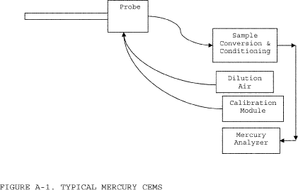
3.2.1.1 Equipment Specifications.
3.2.1.1.1 Materials of Construction. All wetted sampling system components, including probe components prior to the point at which the calibration gas is introduced, must be chemically inert to all Hg species. Materials such as perfluoroalkoxy (PFA) Teflon TM, quartz, and treated stainless steel (SS) are examples of such materials.
3.2.1.1.2 Temperature Considerations. All system components prior to the Hg +2 to Hg 0 converter must be maintained at a sample temperature above the acid gas dew point.
3.2.1.1.3 Measurement System Components.
3.2.1.1.3.1 Sample Probe. The probe must be made of the appropriate materials as noted in paragraph 3.2.1.1.1 of this section, heated when necessary, as described in paragraph 3.2.1.1.3.4 of this section, and configured with ports for introduction of calibration gases.
3.2.1.1.3.2 Filter or Other Particulate Removal Device. The filter or other particulate removal device is part of the measurement system, must be made of appropriate materials, as noted in paragraph 3.2.1.1.1 of this section, and must be included in all system tests.
3.2.1.1.3.3 Sample Line. The sample line that connects the probe to the converter, conditioning system, and analyzer must be made of appropriate materials, as noted in paragraph 3.2.1.1.1 of this section.
3.2.1.1.3.4 Conditioning Equipment. For wet basis systems, such as the one shown in Figure A-1, the sample must be kept above its dew point either by: heating the sample line and all sample transport components up to the inlet of the analyzer (and, for hot-wet extractive systems, also heating the analyzer); or diluting the sample prior to analysis using a dilution probe system. The components required for these operations are considered to be conditioning equipment. For dry basis measurements, a condenser, dryer or other suitable device is required to remove moisture continuously from the sample gas, and any equipment needed to heat the probe or sample line to avoid condensation prior to the moisture removal component is also required.
3.2.1.1.3.5 Sampling Pump. A pump is needed to push or pull the sample gas through the system at a flow rate sufficient to minimize the response time of the measurement system. If a mechanical sample pump is used and its surfaces are in contact with the sample gas prior to detection, the pump must be leak free and must be constructed of a material that is non-reactive to the gas being sampled (see paragraph 3.2.1.1.1 of this section). For dilution-type measurement systems, such as the system shown in Figure A-1, an ejector pump (eductor) may be used to create a sufficient vacuum that sample gas will be drawn through a critical orifice at a constant rate. The ejector pump must be constructed of any material that is non-reactive to the gas being sampled.
3.2.1.1.3.6 Calibration Gas System(s). Design and equip each Hg CEMS to permit the introduction of known concentrations of elemental Hg and HgCl2 separately, at a point preceding the sample extraction filtration system, such that the entire measurement system can be checked. The calibration gas system(s) must be designed so that the flow rate exceeds the sampling system flow requirements and that the gas is delivered to the CEMS at atmospheric pressure.
3.2.1.1.3.7 Sample Gas Delivery. The sample line may feed directly to either a converter, a by-pass valve (for Hg speciating systems), or a sample manifold. All valve and/or manifold components must be made of material that is non-reactive to the gas sampled and the calibration gas, and must be configured to safely discharge any excess gas.
3.2.1.1.3.8 Hg Analyzer. An instrument is required that continuously measures the total vapor phase Hg concentration in the gas stream. The analyzer may also be capable of measuring elemental and oxidized Hg separately.
3.2.1.1.3.9 Data Recorder. A recorder, such as a computerized data acquisition and handling system (DAHS), digital recorder, or data logger, is required for recording measurement data.
3.2.1.2 Reagents and Standards.
3.2.1.2.1 NIST Traceability. Only NIST-certified or NIST-traceable calibration gas standards and reagents (as defined in paragraphs 3.1.4 and 3.1.5 of this appendix), and including, but not limited to, Hg gas generators and Hg gas cylinders, shall be used for the tests and procedures required under this subpart. Calibration gases with known concentrations of Hg 0 and HgCl2 are required. Special reagents and equipment may be needed to prepare the Hg 0 and HgCl2 gas standards (e.g., NIST-traceable solutions of HgCl2 and gas generators equipped with mass flow controllers).
3.2.1.2.2 Required Calibration Gas Concentrations.
3.2.1.2.2.1 Zero-Level Gas. A zero-level calibration gas with a Hg concentration below the level detectable by the Hg analyzer is required for calibration error tests and cycle time tests of the CEMS.
3.2.1.2.2.2 Low-Level Gas. A low-level calibration gas with a Hg concentration of 20 to 30 percent of the span value is required for linearity checks and 3-level system integrity checks of the CEMS. Elemental Hg standards are required for the linearity checks and oxidized Hg standards are required for the system integrity checks.
3.2.1.2.2.3 Mid-Level Gas. A mid-level calibration gas with a Hg concentration of 50 to 60 percent of the span value is required for linearity checks and for 3-level system integrity checks of the CEMS, and is optional for calibration error tests and single-level system integrity checks. Elemental Hg standards are required for the linearity checks, oxidized Hg standards are required for the system integrity checks, and either elemental or oxidized Hg standards may be used for the calibration error tests.
3.2.1.2.2.4 High-Level Gas. A high-level calibration gas with a Hg concentration of 80 to 100 percent of the span value is required for linearity checks, 3-level system integrity checks, and cycle time tests of the CEMS, and is optional for calibration error tests and single-level system integrity checks. Elemental Hg standards are required for the linearity checks, oxidized Hg standards are required for the system integrity checks, and either elemental or oxidized Hg standards may be used for the calibration error and cycle time tests.
3.2.1.3 Installation and Measurement Location. For the Hg CEMS and any additional monitoring system(s) needed to convert Hg concentrations to the desired units of measure (i.e., a flow monitor, CO2 or O2 monitor, and/or moisture monitor, as applicable), install each monitoring system at a location: that is consistent with 63.10010(a); that represents the emissions exiting to the atmosphere; and where it is likely that the CEMS can pass the relative accuracy test.
3.2.1.4 Monitor Span and Range Requirements. Determine the appropriate span and range value(s) for the Hg CEMS as described in paragraphs 3.2.1.4.1 through 3.2.1.4.3 of this section.
3.2.1.4.1 Maximum Potential Concentration. There are three options for determining the maximum potential Hg concentration (MPC). Option 1 applies to coal combustion. You may use a default value of 10 µg/scm for all coal ranks (including coal refuse) except for lignite; for lignite, use 16 µg/scm. If different coals are blended as part of normal operation, use the highest MPC for any fuel in the blend. Option 2 is to base the MPC on the results of site-specific Hg emission testing. This option may be used only if the unit does not have add-on Hg emission controls or a flue gas desulfurization system, or if testing is performed upstream of all emission control devices. If Option 2 is selected, perform at least three test runs at the normal operating load, and the highest Hg concentration obtained in any of the tests shall be the MPC. Option 3 is to use fuel sampling and analysis to estimate the MPC. To make this estimate, use the average Hg content (i.e., the weight percentage) from at least three representative fuel samples, together with other available information, including, but not limited to the maximum fuel feed rate, the heating value of the fuel, and an appropriate F-factor. Assume that all of the Hg in the fuel is emitted to the atmosphere as vapor-phase Hg.
3.2.1.4.2 Span Value. To determine the span value of the Hg CEMS, multiply the Hg concentration corresponding to the applicable emissions standard by two. If the result of this calculation is an exact multiple of 10 µg/scm, use the result as the span value. Otherwise, round off the result to either: the next highest integer; the next highest multiple of 5 µg/scm; or the next highest multiple of 10 µg/scm.
3.2.1.4.3 Analyzer Range. The Hg analyzer must be capable of reading Hg concentration as high as the MPC.
3.2.2 Sorbent Trap Monitoring System. A sorbent trap monitoring system (as defined in paragraph 3.1.2 of this section) may be used as an alternative to a Hg CEMS. If this option is selected, the monitoring system shall be installed, maintained, and operated in accordance with Performance Specification (PS) 12B in Appendix B to part 60 of this chapter. The system shall be certified in accordance with the provisions of section 4.1.2 of this appendix.
3.2.3 Other Necessary Data Collection. To convert measured hourly Hg concentrations to the units of the applicable emissions standard (i.e., lb/TBtu or lb/GWh), additional data must be collected, as described in paragraphs 3.2.3.1 through 3.2.3.3 of this section. Any additional monitoring systems needed for this purpose must be certified, operated, maintained, and quality-assured according to the applicable provisions of part 75 of this chapter (see §§ 63.10010(b) through (d)). The calculation methods for the types of emission limits described in paragraphs 3.2.3.1 and 3.2.3.2 of this section are presented in section 6.2 of this appendix.
3.2.3.1 Heat Input-Based Emission Limits. For a heat input-based Hg emission limit (i.e., in lb/TBtu), data from a certified CO2 or O2 monitor are needed, along with a fuel-specific F-factor and a conversion constant to convert measured Hg concentration values to the units of the standard. In some cases, the stack gas moisture content must also be considered in making these conversions.
3.2.3.2 Electrical Output-Based Emission Rates. If the applicable Hg limit is electrical output-based (i.e., lb/GWh), hourly electrical load data and unit operating times are required in addition to hourly data from a certified stack gas flow rate monitor and (if applicable) moisture data.
3.2.3.3 Sorbent Trap Monitoring System Operation. Routine operation of a sorbent trap monitoring system requires the use of a certified stack gas flow rate monitor, to maintain an established ratio of stack gas flow rate to sample flow rate.
4. Certification and Recertification Requirements4.1 Certification Requirements. All Hg CEMS and sorbent trap monitoring systems and the additional monitoring systems used to continuously measure Hg emissions in units of the applicable emissions standard in accordance with this appendix must be certified in a timely manner, such that the initial compliance demonstration is completed no later than the applicable date in § 63.9984(f).
4.1.1 Hg CEMS. Table A-1, below, summarizes the certification test requirements and performance specifications for a Hg CEMS. The CEMS may not be used to report quality-assured data until these performance criteria are met. Paragraphs 4.1.1.1 through 4.1.1.5 of this section provide specific instructions for the required tests. All tests must be performed with the affected unit(s) operating (i.e., combusting fuel). Except for the RATA, which must be performed at normal load, no particular load level is required for the certification tests.
4.1.1.1 7-Day Calibration Error Test. Perform the 7-day calibration error test on 7 consecutive source operating days, using a zero-level gas and either a high-level or a mid-level calibration gas standard (as defined in paragraphs 3.1.8, 3.1.10, and 3.1.11 of this appendix). Use a NIST-traceable elemental Hg gas standard (as defined in paragraphs 3.1.4 of this appendix) for the test. If your Hg CEMS lacks an integrated elemental Hg gas generator, you may continue to use NIST-traceable oxidized Hg gases for the 7-day calibration error test (or the daily calibration error check) until such time as NIST-traceable compressed elemental Hg gas standards, at appropriate concentration levels, are available from gas vendors. If moisture is added to the calibration gas, the dilution effect of the moisture and/or chlorine addition on the calibration gas concentration must be accounted for in an appropriate manner. Operate the Hg CEMS in its normal sampling mode during the test. The calibrations should be approximately 24 hours apart, unless the 7-day test is performed over non-consecutive calendar days. On each day of the test, inject the zero-level and upscale gases in sequence and record the analyzer responses. Pass the calibration gas through all filters, scrubbers, conditioners, and other monitor components used during normal sampling, and through as much of the sampling probe as is practical. Do not make any manual adjustments to the monitor (i.e., resetting the calibration) until after taking measurements at both the zero and upscale concentration levels. If automatic adjustments are made following both injections, conduct the calibration error test such that the magnitude of the adjustments can be determined, and use only the unadjusted analyzer responses in the calculations. Calculate the calibration error (CE) on each day of the test, as described in Table A-1 of this appendix. The CE on each day of the test must either meet the main performance specification or the alternative specification in Table A-1 of this appendix.
4.1.1.2 Linearity Check. Perform the linearity check using low, mid, and high-level concentrations of NIST-traceable elemental Hg standards. Three gas injections at each concentration level are required, with no two successive injections at the same concentration level. Introduce the calibration gas at the gas injection port, as specified in section 3.2.1.1.3.6 of this appendix. Operate the CEMS at its normal operating temperature and conditions. Pass the calibration gas through all filters, scrubbers, conditioners, and other components used during normal sampling, and through as much of the sampling probe as is practical. If moisture and/or chlorine is added to the calibration gas, the dilution effect of the moisture and/or chlorine addition on the calibration gas concentration must be accounted for in an appropriate manner. Record the monitor response from the data acquisition and handling system for each gas injection. At each concentration level, use the average analyzer response to calculate the linearity error (LE), as described in Table A-1. The LE must either meet the main performance specification or the alternative specification in Table A-1.
4.1.1.3 Three-Level System Integrity Check. Perform the 3-level system integrity check using low, mid, and high-level calibration gas concentrations generated by a NIST-traceable source of oxidized Hg. If your Hg CEMS lacks an integrated elemental Hg gas generator, you may continue to use NIST-traceable oxidized Hg gases for the 7-day calibration error test (or the daily calibration error check) until such time as NIST-traceable compressed elemental Hg gas standards, at appropriate concentration levels, are available from gas vendors. Follow the same basic procedure as for the linearity check. If moisture and/or chlorine is added to the calibration gas, the dilution effect of the moisture and/or chlorine addition on the calibration gas concentration must be accounted for in an appropriate manner. Calculate the system integrity error (SIE), as described in Table A-1 of this appendix. The SIE must either meet the main performance specification or the alternative specification in Table A-1 of this appendix.
Table A-1 - Required Certification Tests and Performance Specifications for Hg CEMS
| For this required certification test . . . | The main performance specification 1 is . . . | The alternate performance specification 1 is . . . | And the conditions of the alternate specification are . . . |
|---|---|---|---|
| 7-day calibration error test 2 6 | |R − A| ≤ 5.0% of span value, for both the zero and upscale gases, on each of the 7 days. | |R − A| ≤ 1.0 µg/scm | The alternate specification may be used on any day of the test. |
| Linearity check 3 6 | |R − Aavg | ≤ 10.0% of the reference gas concentration at each calibration gas level (low, mid, or high). | |R − Aavg | ≤ 0.8 µg/scm | The alternate specification may be used at any gas level. |
| 3-level system integrity check 4 | |R − Aavg | ≤ 10.0% of the reference gas concentration at each calibration gas level. | |R − Aavg | ≤ 0.8 µg/scm | The alternate specification may be used at any gas level. |
| RATA | 20.0% RA | |RMavg − Cavg| + |CC| ≤ 0.5 µg/scm 7 | RMavg < 2.5µg/scm |
| Cycle time test 5 | 15 minutes where the stability criteria are readings change by < 2.0% of span or by ≤ 0.5 µg/scm, for 2 minutes. |
1 Note that |R − A| is the absolute value of the difference between the reference gas value and the analyzer reading. |R − Aavg| is the absolute value of the difference between the reference gas concentration and the average of the analyzer responses, at a particular gas level.
2 Use elemental Hg standards; a mid-level or high-level upscale gas may be used.
3 Use elemental Hg standards.
4 Use oxidized Hg standards.
5 Use elemental Hg standards; a high-level upscale gas must be used. The cycle time test is not required for Hg CEMS that use integrated batch sampling; however, those monitoring systems must be capable of recording at least one Hg concentration reading every 15 minutes.
6 If your Hg CEMS lacks an integrated elemental Hg gas generator, you may continue to use NIST-traceable oxidized Hg gases until such time as NIST-traceable compressed elemental Hg gas standards, at appropriate concentration levels, are available from gas vendors.
7 Note that |RMavg − Cavg| is the absolute difference between the mean reference method value and the mean CEMS value from the RATA; CC is the confidence coefficient from Equation 2-5 of Performance Specification 2 in appendix B to part 60 of this chapter.
4.1.1.4 Cycle Time Test. Perform the cycle time test, using a zero-level gas and a high-level calibration gas.
Either an elemental or oxidized NIST-traceable Hg standard may be used as the high-level gas. Perform the test in two stages - upscale and downscale. The slower of the upscale and downscale response times is the cycle time for the CEMS. Begin each stage of the test by injecting calibration gas after achieving a stable reading of the stack emissions. The cycle time is the amount of time it takes for the analyzer to register a reading that is 95 percent of the way between the stable stack emissions reading and the final, stable reading of the calibration gas concentration. Use the following criterion to determine when a stable reading of stack emissions or calibration gas has been attained - the reading is stable if it changes by no more than 2.0 percent of the span value or 0.5 µg/scm (whichever is less restrictive) for two minutes, or a reading with a change of less than 6.0 percent from the measured average concentration over 6 minutes. Integrated batch sampling type Hg CEMS are exempted from this test; however, these systems must be capable of delivering a measured Hg concentration reading at least once every 15 minutes. If necessary to increase measurement sensitivity of a batch sampling type Hg CEMS for a specific application, you may petition the Administrator for approval of a time longer than 15 minutes between readings.
4.1.1.5 Relative Accuracy Test Audit (RATA). Perform the RATA of the Hg CEMS at normal load. Acceptable Hg reference methods for the RATA include ASTM D6784-02 (Reapproved 2008), “Standard Test Method for Elemental, Oxidized, Particle-Bound and Total Mercury in Flue Gas Generated from Coal-Fired Stationary Sources (Ontario Hydro Method)” (incorporated by reference, see § 63.14) and Methods 29, 30A, and 30B in appendix A-8 to part 60 of this chapter. When Method 29 or ASTM D6784-02 is used, paired sampling trains are required and the filterable portion of the sample need not be included when making comparisons to the Hg CEMS results for purposes of a RATA. To validate a Method 29 or ASTM D6784-02 test run, calculate the relative deviation (RD) using Equation A-1 of this section, and assess the results as follows to validate the run. The RD must not exceed 10 percent, when the average Hg concentration is greater than 1.0 µg/dscm. If the RD specification is met, the results of the two samples shall be averaged arithmetically.
 Where: RD
= Relative Deviation between the Hg concentrations of samples “a”
and “b” (percent), Ca = Hg concentration of Hg sample “a” (µ
g/dscm), and Cb = Hg concentration of Hg sample “b” (µ g/dscm).
Where: RD
= Relative Deviation between the Hg concentrations of samples “a”
and “b” (percent), Ca = Hg concentration of Hg sample “a” (µ
g/dscm), and Cb = Hg concentration of Hg sample “b” (µ g/dscm).
4.1.1.5.1 Special Considerations. A minimum of nine valid test runs must be performed, directly comparing the CEMS measurements to the reference method. More than nine test runs may be performed. If this option is chosen, the results from a maximum of three test runs may be rejected so long as the total number of test results used to determine the relative accuracy is greater than or equal to nine; however, all data must be reported including the rejected data. The minimum time per run is 21 minutes if Method 30A is used. If Method 29, Method 30B, or ASTM D6784-02 (Reapproved 2008), “Standard Test Method for Elemental, Oxidized, Particle-Bound and Total Mercury in Flue Gas Generated from Coal-Fired Stationary Sources (Ontario Hydro Method)” (incorporated by reference, see § 63.14) is used, the time per run must be long enough to collect a sufficient mass of Hg to analyze. Complete the RATA within 168 unit operating hours, except when Method 29 or ASTM D6784-02 is used, in which case up to 336 operating hours may be taken to finish the test.
4.1.1.5.2 Calculation of RATA Results. Calculate the relative accuracy (RA) of the monitoring system, on a µg/scm basis, as described in section 12 of Performance Specification (PS) 2 in appendix B to part 60 of this chapter (see Equations 2 - 3 through 2-6 of PS 2). For purposes of calculating the relative accuracy, ensure that the reference method and monitoring system data are on a consistent basis, either wet or dry. The CEMS must either meet the main performance specification or the alternative specification in Table A-1 of this appendix.
4.1.1.5.3 Bias Adjustment. Measurement or adjustment of Hg CEMS data for bias is not required.
4.1.2 Sorbent Trap Monitoring Systems. For the initial certification of a sorbent trap monitoring system, only a RATA is required.
4.1.2.1 Reference Methods. The acceptable reference methods for the RATA of a sorbent trap monitoring system are the same as those listed in paragraph 4.1.1.5 of this section.
4.1.2.2 “The special considerations specified in paragraph 4.1.1.5.1 of this section apply to the RATA of a sorbent trap monitoring system. During the RATA, the monitoring system must be operated and quality-assured in accordance with Performance Specification (PS) 12B in Appendix B to part 60 of this chapter with the following exceptions for sorbent trap section 2 breakthrough:
4.1.2.2.1 For stack Hg concentrations >1 µg/dscm, ≤10% of section 1 Hg mass;
4.1.2.2.2 For stack Hg concentrations ≤1 µg/dscm and >0.5 µg/dscm, ≤20% of section 1 Hg mass;
4.1.2.2.3 For stack Hg concentrations ≤0.5 µg/dscm and >0.1 µg/dscm, ≤50% of section 1 Hg mass; and
4.1.2.2.4 For stack Hg concentrations ≤0.1µg/dscm, no breakthrough criterion assuming all other QA/QC specifications are met.
4.1.2.3 The type of sorbent material used by the traps during the RATA must be the same as for daily operation of the monitoring system; however, the size of the traps used for the RATA may be smaller than the traps used for daily operation of the system.
4.1.2.4 Calculation of RATA Results. Calculate the relative accuracy (RA) of the sorbent trap monitoring system, on a µg/scm basis, as described in section 12 of Performance Specification (PS) 2 in appendix B to part 60 of this chapter (see Equations 2-3 through 2-6 of PS2). For purposes of calculating the relative accuracy, ensure that the reference method and monitoring system data are on a consistent moisture basis, either wet or dry.The main and alternative RATA performance specifications in Table A-1 for Hg CEMS also apply to the sorbent trap monitoring system.
4.1.2.5 Bias Adjustment. Measurement or adjustment of sorbent trap monitoring system data for bias is not required.
4.1.3 Diluent Gas, Flow Rate, and/or Moisture Monitoring Systems. Monitoring systems that are used to measure stack gas volumetric flow rate, diluent gas concentration, or stack gas moisture content, either for routine operation of a sorbent trap monitoring system or to convert Hg concentration data to units of the applicable emission limit, must be certified in accordance with the applicable provisions of part 75 of this chapter.
4.2 Recertification. Whenever the owner or operator makes a replacement, modification, or change to a certified CEMS or sorbent trap monitoring system that may significantly affect the ability of the system to accurately measure or record pollutant or diluent gas concentrations, stack gas flow rates, or stack gas moisture content, the owner or operator shall recertify the monitoring system. Furthermore, whenever the owner or operator makes a replacement, modification, or change to the flue gas handling system or the unit operation that may significantly change the concentration or flow profile, the owner or operator shall recertify the monitoring system. The same tests performed for the initial certification of the monitoring system shall be repeated for recertification, unless otherwise specified by the Administrator. Examples of changes that require recertification include: replacement of a gas analyzer; complete monitoring system replacement, and changing the location or orientation of the sampling probe.
5. Ongoing Quality Assurance (QA) and Data Validation5.1 Hg CEMS.
5.1.1 Required QA Tests. Periodic QA testing of each Hg CEMS is required following initial certification. The required QA tests, the test frequencies, and the performance specifications that must be met are summarized in Table A-2, below. All tests must be performed with the affected unit(s) operating (i.e., combusting fuel), however, the daily calibration may optionally be performed off-line. The RATA must be performed at normal load, but no particular load level is required for the other tests. For each test, follow the same basic procedures in section 4.1.1 of this appendix that were used for initial certification.
5.1.2 Test Frequency. The frequency for the required QA tests of the Hg CEMS shall be as follows:
5.1.2.1 Calibration error tests of the Hg CEMS are required daily, except during unit outages. Use a NIST-traceable elemental Hg gas standard for these calibrations. If your Hg CEMS lacks an integrated elemental Hg gas generator, you may continue to use NIST-traceable oxidized Hg gases for the 7-day calibration error test (or the daily calibration error check) until such time as NIST-traceable compressed elemental Hg gas standards, at appropriate concentration levels, are available from gas vendors. Both a zero-level gas and either a mid-level or high-level gas are required for these calibrations.
5.1.2.2 Perform a linearity check of the Hg CEMS in each QA operating quarter, using low-level, mid-level, and high-level NIST-traceable elemental Hg standards. For units that operate infrequently, limited exemptions from this test are allowed for “non-QA operating quarters”. A maximum of three consecutive exemptions for this reason are permitted, following the quarter of the last test. After the third consecutive exemption, a linearity check must be performed in the next calendar quarter or within a grace period of 168 unit or stack operating hours after the end of that quarter. The test frequency for 3-level system integrity checks (if performed in lieu of linearity checks) is the same as for the linearity checks. Use low-level, mid-level, and high-level NIST-traceable oxidized Hg standards for the system integrity checks.
5.1.2.3 Perform a single-level system integrity check weekly, i.e., once every 7 operating days (see the third column in Table A-2 of this appendix).
5.1.2.4 The test frequency for the RATAs of the Hg CEMS shall be annual, i.e., once every four QA operating quarters. For units that operate infrequently, extensions of RATA deadlines are allowed for non-QA operating quarters. Following a RATA, if there is a subsequent non-QA quarter, it extends the deadline for the next test by one calendar quarter. However, there is a limit to these extensions; the deadline may not be extended beyond the end of the eighth calendar quarter after the quarter of the last test. At that point, a RATA must either be performed within the eighth calendar quarter or in a 720 hour unit or stack operating hour grace period following that quarter. When a required annual RATA is done within a grace period, the deadline for the next RATA is three QA operating quarters after the quarter in which the grace period test is performed.
5.1.3 Grace Periods.
5.1.3.1 A 168 unit or stack operating hour grace period is available for quarterly linearity checks and 3-level system integrity checks of the Hg CEMS.
5.1.3.2 A 720 unit or stack operating hour grace period is available for RATAs of the Hg CEMS.
5.1.3.3 There is no grace period for weekly system integrity checks. The test must be completed once every 7 operating days.
5.1.4 Data Validation. The Hg CEMS is considered to be out-of-control, and data from the CEMS may not be reported as quality-assured, when any one of the acceptance criteria for the required QA tests in Table A-2 is not met. The CEMS is also considered to be out-of-control when a required QA test is not performed on schedule or within an allotted grace period. To end an out-of-control period, the QA test that was either failed or not done on time must be performed and passed. Out-of-control periods are counted as hours of monitoring system downtime.
5.1.5 Conditional Data Validation. For certification, recertification, and diagnostic testing of Hg monitoring systems, and for the required QA tests when non-redundant backup Hg monitoring systems or temporary like-kind Hg analyzers are brought into service, the conditional data validation provisions in §§ 75.20(b)(3)(ii) through (b)(3)(ix) of this chapter may be used to avoid or minimize data loss. The allotted window of time to complete 7-day calibration error tests, linearity checks, cycle time tests, and RATAs shall be as specified in § 75.20(b)(3)(iv) of this chapter. Required system integrity checks must be completed within 168 unit or stack operating hours after the probationary calibration error test.
Table A-2 - On-Going QA Test Requirements for Hg CEMS
| Perform this type of QA test . . . | At this frequency . . . | With these qualifications and exceptions . . . | Acceptance criteria . . . |
|---|---|---|---|
| Calibration error test 5 | Daily | • Use either a mid- or
high-level gas • Use elemental Hg • Calibrations are not required when the unit is not in operation. |
|R − A| ≤ 5.0% of span
value or |R − A| ≤ 1.0 µg/scm. |
| Single-level system integrity check | Weekly 1 | • Use oxidized Hg - either mid- or high-level | |R − Aavg| ≤ 10.0% of the
reference gas value or |R − Aavg| ≤ 0.8 µg/scm. |
| Linearity check or 3-level system integrity check | Quarterly 3 | • Required in each “QA
operating quarter” 2 and no less than once every 4
calendar quarters • 168 operating hour grace period available • Use elemental Hg for linearity check • Use oxidized Hg for system integrity check |
|R − Aavg | ≤ 10.0% of the
reference gas value, at each calibration gas level or |R − Aavg| ≤ 0.8 µg/scm. |
| RATA | Annual 4 | • Test deadline may be
extended for “non-QA operating quarters,” up to a maximum of 8
quarters from the quarter of the previous test • 720 operating hour grace period available |
≤20.0% RA or |RMavg − Cavg | + |CC| ≤ 0.5 µg/scm, if RMavg < 2.5 µg/scm. |
1 “Weekly” means once every 7 operating days.
2 A “QA operating quarter” is a calendar quarter with at least 168 unit or stack operating hours.
3 “Quarterly” means once every QA operating quarter.
4 “Annual” means once every four QA operating quarters.
5 If your Hg CEMS lacks an integrated elemental Hg gas generator, you may continue to use NIST-traceable oxidized Hg gases until such time as NIST-traceable compressed elemental Hg gas standards, at appropriate concentration levels, are available from gas vendors.
5.1.6 Adjustment of Span. If you discover that a span adjustment is needed (e.g., if the Hg concentration readings exceed the span value for a significant percentage of the unit operating hours in a calendar quarter), you must implement the span adjustment within 90 days after the end of the calendar quarter in which you identify the need for the adjustment. A diagnostic linearity check is required within 168 unit or stack operating hours after changing the span value.
5.2 Sorbent Trap Monitoring Systems.
5.2.1 Each sorbent trap monitoring system shall be continuously operated and maintained in accordance with Performance Specification (PS) 12B in appendix B to part 60 of this chapter. The QA/QC criteria for routine operation of the system are summarized in Table 12B-1 of PS 12B. Each pair of sorbent traps may be used to sample the stack gas for up to 15 operating days.
5.2.2 For ongoing QA, periodic RATAs of the system are required.
5.2.2.1 The RATA frequency shall be annual, i.e., once every four QA operating quarters. The provisions in section 5.1.2.4 of this appendix pertaining to RATA deadline extensions also apply to sorbent trap monitoring systems.
5.2.2.2 The same RATA performance criteria specified in Table A-2 for Hg CEMS also apply to the annual RATAs of the sorbent trap monitoring system.
5.2.2.3 A 720 unit or stack operating hour grace period is available for RATAs of the monitoring system.
5.2.3 Data validation for sorbent trap monitoring systems shall be done in accordance with Table 12B-1 in Performance Specification (PS) 12B in appendix B to part 60 of this chapter. All periods of invalid data shall be counted as hours of monitoring system downtime.
5.3 Flow Rate, Diluent Gas, and Moisture Monitoring Systems. The on-going QA test requirements for these monitoring systems are specified in part 75 of this chapter (see §§ 63.10010(b) through (d)).
5.4 QA/QC Program Requirements. The owner or operator shall develop and implement a quality assurance/quality control (QA/QC) program for the Hg CEMS and/or sorbent trap monitoring systems that are used to provide data under this subpart. At a minimum, the program shall include a written plan that describes in detail (or that refers to separate documents containing) complete, step-by-step procedures and operations for the most important QA/QC activities. Electronic storage of the QA/QC plan is permissible, provided that the information can be made available in hard copy to auditors and inspectors. The QA/QC program requirements for the diluent gas, flow rate, and moisture monitoring systems described in section 3.2.1.3 of this appendix are specified in section 1 of appendix B to part 75 of this chapter.
5.4.1 General Requirements.
5.4.1.1 Preventive Maintenance. Keep a written record of procedures needed to maintain the Hg CEMS and/or sorbent trap monitoring system(s) in proper operating condition and a schedule for those procedures. Include, at a minimum, all procedures specified by the manufacturers of the equipment and, if applicable, additional or alternate procedures developed for the equipment.
5.4.1.2 Recordkeeping and Reporting. Keep a written record describing procedures that will be used to implement the recordkeeping and reporting requirements of this appendix.
5.4.1.3 Maintenance Records. Keep a record of all testing, maintenance, or repair activities performed on any Hg CEMS or sorbent trap monitoring system in a location and format suitable for inspection. A maintenance log may be used for this purpose. The following records should be maintained: date, time, and description of any testing, adjustment, repair, replacement, or preventive maintenance action performed on any monitoring system and records of any corrective actions associated with a monitor outage period. Additionally, any adjustment that may significantly affect a system's ability to accurately measure emissions data must be recorded (e.g., changing the dilution ratio of a CEMS), and a written explanation of the procedures used to make the adjustment(s) shall be kept.
5.4.2 Specific Requirements for Hg CEMS.
5.4.2.1 Daily Calibrations, Linearity Checks and System Integrity Checks. Keep a written record of the procedures used for daily calibrations of the Hg CEMS. If moisture and/or chlorine is added to the Hg calibration gas, document how the dilution effect of the moisture and/or chlorine addition on the calibration gas concentration is accounted for in an appropriate manner. Also keep records of the procedures used to perform linearity checks of the Hg CEMS and the procedures for system integrity checks of the Hg CEMS. Document how the test results are calculated and evaluated.
5.4.2.2 Monitoring System Adjustments. Document how each component of the Hg CEMS will be adjusted to provide correct responses to calibration gases after routine maintenance, repairs, or corrective actions.
5.4.2.3 Relative Accuracy Test Audits. Keep a written record of procedures used for RATAs of the Hg CEMS. Indicate the reference methods used and document how the test results are calculated and evaluated.
5.4.3 Specific Requirements for Sorbent Trap Monitoring Systems.
5.4.3.1 Sorbent Trap Identification and Tracking. Include procedures for inscribing or otherwise permanently marking a unique identification number on each sorbent trap, for chain of custody purposes. Keep records of the ID of the monitoring system in which each sorbent trap is used, and the dates and hours of each Hg collection period.
5.4.3.2 Monitoring System Integrity and Data Quality. Document the procedures used to perform the leak checks when a sorbent trap is placed in service and removed from service. Also Document the other QA procedures used to ensure system integrity and data quality, including, but not limited to, gas flow meter calibrations, verification of moisture removal, and ensuring air-tight pump operation. In addition, the QA plan must include the data acceptance and quality control criteria in Table 12B-1 in section 9.0 of Performance Specification (PS) 12B in Appendix B to part 60 of this chapter. All reference meters used to calibrate the gas flow meters (e.g., wet test meters) shall be periodically recalibrated. Annual, or more frequent, recalibration is recommended. If a NIST-traceable calibration device is used as a reference flow meter, the QA plan must include a protocol for ongoing maintenance and periodic recalibration to maintain the accuracy and NIST-traceability of the calibrator.
5.4.3.3 Hg Analysis. Explain the chain of custody employed in packing, transporting, and analyzing the sorbent traps. Keep records of all Hg analyses. The analyses shall be performed in accordance with the procedures described in section 11.0 of Performance Specification (PS) 12B in Appendix B to part 60 of this chapter.
5.4.3.4 Data Collection Period. State, and provide the rationale for, the minimum acceptable data collection period (e.g., one day, one week, etc.) for the size of sorbent trap selected for the monitoring. Address such factors as the Hg concentration in the stack gas, the capacity of the sorbent trap, and the minimum mass of Hg required for the analysis. Each pair of sorbent traps may be used to sample the stack gas for up to 14 operating days.
5.4.3.5 Relative Accuracy Test Audit Procedures. Keep records of the procedures and details peculiar to the sorbent trap monitoring systems that are to be followed for relative accuracy test audits, such as sampling and analysis methods.
6. Data Reduction and Calculations6.1 Data Reduction.
6.1.1 Reduce the data from Hg CEMS to hourly averages, in accordance with § 60.13(h)(2) of this chapter.
6.1.2 For sorbent trap monitoring systems, determine the Hg concentration for each data collection period and assign this concentration value to each operating hour in the data collection period.
6.1.3 For any operating hour in which valid data are not obtained, either for Hg concentration or for a parameter used in the emissions calculations (i.e., flow rate, diluent gas concentration, or moisture, as applicable), do not calculate the Hg emission rate for that hour. For the purposes of this appendix, part 75 substitute data values are not considered to be valid data.
6.1.4 Operating hours in which valid data are not obtained for Hg concentration are considered to be hours of monitor downtime. The use of substitute data for Hg concentration is not required.
6.2 Calculation of Hg Emission Rates. Use the applicable calculation methods in paragraphs 6.2.1 and 6.2.2 of this section to convert Hg concentration values to the appropriate units of the emission standard.
6.2.1 Heat Input-Based Hg Emission Rates. Calculate hourly heat input-based Hg emission rates, in units of lb/TBtu, according to sections 6.2.1.1 through 6.2.1.4 of this appendix.
6.2.1.1 Select an appropriate emission rate equation from among Equations 19-1 through 19-9 in EPA Method 19 in appendix A-7 to part 60 of this chapter.
6.2.1.2 Calculate the Hg emission rate in lb/MMBtu, using the equation selected from Method 19. Multiply the Hg concentration value by 6.24 × 10⁻¹¹ to convert it from µg/scm to lb/scf. In cases where an appropriate F-factor is not listed in Table 19-2 of Method 19, you may use F-factors from Table 1 in section 3.3.5 of appendix F to part 75 of this chapter, or F-factors derived using the procedures in section 3.3.6 of appendix to part 75 of this chapter. Also, for startup and shutdown hours, you may calculate the Hg emission rate using the applicable diluent cap value specified in section 3.3.4.1 of appendix F to part 75 of this chapter, provided that the diluent gas monitor is not out-of-control and the hourly average O2 concentration is above 14.0% O2 (19.0% for an IGCC) or the hourly average CO2 concentration is below 5.0% CO2 (1.0% for an IGCC), as applicable.
6.2.1.3 Multiply the lb/MMBtu value obtained in section 6.2.1.2 of this appendix by 10 6 to convert it to lb/TBtu.
6.2.1.4 The heat input-based Hg emission rate limit in Table 2 to this subpart must be met on a 30 boiler operating day rolling average basis, except as otherwise provided in § 63.10009(a)(2). Use Equation 19-19 in EPA Method 19 to calculate the Hg emission rate for each averaging period. The term Ehj in Equation 19-19 must be in the units of the applicable emission limit. Do not include non-operating hours with zero emissions in the average.
6.2.2 Electrical Output-Based Hg Emission Rates. Calculate electrical output-based Hg emission limits in units of lb/GWh, according to sections 6.2.2.1 through 6.2.2.3 of this appendix.
6.2.2.1 Calculate the Hg mass emissions for each operating hour in which valid data are obtained for all parameters, using Equation A-2 of this section (for wet-basis measurements of Hg concentration) or Equation A-3 of this section (for dry-basis measurements), as applicable:
 Where: Mh
= Hg mass emission rate for the hour (lb/h) K = Units conversion
constant, 6.24 × 10⁻¹¹ lb-scm/µg-scf, Ch = Hourly average Hg
concentration, wet basis (µg/scm) Qh = Stack gas volumetric flow
rate for the hour (scfh).
Where: Mh
= Hg mass emission rate for the hour (lb/h) K = Units conversion
constant, 6.24 × 10⁻¹¹ lb-scm/µg-scf, Ch = Hourly average Hg
concentration, wet basis (µg/scm) Qh = Stack gas volumetric flow
rate for the hour (scfh).
(Note: Use unadjusted flow rate values; bias adjustment is not required)
 Where: Mh
= Hg mass emission rate for the hour (lb/h) K = Units conversion
constant, 6.24 × 10⁻¹¹ lb-scm/µg-scf. Ch = Hourly average Hg
concentration, dry basis (µg/dscm). Qh = Stack gas volumetric flow
rate for the hour (scfh) (Note: Use unadjusted flow rate values;
bias adjustment is not required). Bws = Moisture fraction of the
stack gas, expressed as a decimal (equal to % H2O/100)
Where: Mh
= Hg mass emission rate for the hour (lb/h) K = Units conversion
constant, 6.24 × 10⁻¹¹ lb-scm/µg-scf. Ch = Hourly average Hg
concentration, dry basis (µg/dscm). Qh = Stack gas volumetric flow
rate for the hour (scfh) (Note: Use unadjusted flow rate values;
bias adjustment is not required). Bws = Moisture fraction of the
stack gas, expressed as a decimal (equal to % H2O/100)
6.2.2.2 Use Equation A-4 of this section to calculate the emission rate for each unit or stack operating hour in which valid data are obtained for all parameters.
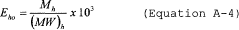 Where:
Eho = Electrical output-based Hg emission rate (lb/GWh). Mh = Hg
mass emission rate for the hour, from Equation A-2 or A-3 of this
section, as applicable (lb/h). (MW)h = Gross electrical load for
the hour, in megawatts (MW). 10 3 = Conversion factor from
megawatts to gigawatts.
Where:
Eho = Electrical output-based Hg emission rate (lb/GWh). Mh = Hg
mass emission rate for the hour, from Equation A-2 or A-3 of this
section, as applicable (lb/h). (MW)h = Gross electrical load for
the hour, in megawatts (MW). 10 3 = Conversion factor from
megawatts to gigawatts.
6.2.2.3 The applicable gross output-based Hg emission rate limit in Table 1 or 2 to this subpart must be met on a 30- (or 90-) boiler operating day rolling average basis, except as otherwise provided in § 63.10009(a)(2). Use Equation A-5 of this appendix to calculate the Hg emission rate for each averaging period.
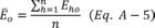 Where: Eo
= Hg emission rate for the averaging period (lb/GWh), Eho = Gross
output-based hourly Hg emission rate for unit or stack sampling
hour “h” in the averaging period, from Equation A-4 of this
appendix (lb/GWh), and n = Number of unit or stack operating hours
in the averaging period in which valid data were obtained for all
parameters. (Note: Do not include non-operating hours with
zero emission rates in the average). 7. Recordkeeping and Reporting
Where: Eo
= Hg emission rate for the averaging period (lb/GWh), Eho = Gross
output-based hourly Hg emission rate for unit or stack sampling
hour “h” in the averaging period, from Equation A-4 of this
appendix (lb/GWh), and n = Number of unit or stack operating hours
in the averaging period in which valid data were obtained for all
parameters. (Note: Do not include non-operating hours with
zero emission rates in the average). 7. Recordkeeping and Reporting
7.1 Recordkeeping Provisions. For the Hg CEMS and/or sorbent trap monitoring systems and any other necessary monitoring systems installed at each affected unit, the owner or operator must maintain a file of all measurements, data, reports, and other information required by this appendix in a form suitable for inspection, for 5 years from the date of each record, in accordance with § 63.10033. The file shall contain the information in paragraphs 7.1.1 through 7.1.10 of this section.
7.1.1 Monitoring Plan Records. For each affected unit or group of units monitored at a common stack, the owner or operator shall prepare and maintain a monitoring plan for the Hg CEMS and/or sorbent trap monitoring system(s) and any other monitoring system(s) (i.e., flow rate, diluent gas, or moisture systems) needed for routine operation of a sorbent trap monitoring system or to convert Hg concentrations to units of the applicable emission standard. The monitoring plan shall contain essential information on the continuous monitoring systems and shall Document how the data derived from these systems ensure that all Hg emissions from the unit or stack are monitored and reported.
7.1.1.1 Updates. Whenever the owner or operator makes a replacement, modification, or change in a certified continuous monitoring system that is used to provide data under this subpart (including a change in the automated data acquisition and handling system or the flue gas handling system) which affects information reported in the monitoring plan (e.g., a change to a serial number for a component of a monitoring system), the owner or operator shall update the monitoring plan.
7.1.1.2 Contents of the Monitoring Plan. For Hg CEMS and sorbent trap monitoring systems, the monitoring plan shall contain the information in sections 7.1.1.2.1 and 7.1.1.2.2 of this appendix, as applicable. For stack gas flow rate, diluent gas, and moisture monitoring systems, the monitoring plan shall include the information required for those systems under § 75.53 (g) of this chapter.
7.1.1.2.1 Electronic. The electronic monitoring plan records must include the following: unit or stack ID number(s); monitoring location(s); the Hg monitoring methodologies used; emissions controls; Hg monitoring system information, including, but not limited to: Unique system and component ID numbers; the make, model, and serial number of the monitoring equipment; the sample acquisition method; formulas used to calculate Hg emissions; and Hg monitor span and range information. The electronic monitoring plan shall be evaluated and submitted using the ECMPS Client Tool provided by the Clean Air Markets Division in the Office of Atmospheric Programs of the EPA.
7.1.1.2.2 Hard Copy. Keep records of the following: schematics and/or blueprints showing the location of the Hg monitoring system(s) and test ports; data flow diagrams; test protocols; monitor span and range calculations; miscellaneous technical justifications.
7.1.2 Operating Parameter Records. The owner or operator shall record the following information for each operating hour of each affected unit and also for each group of units utilizing a common stack, to the extent that these data are needed to convert Hg concentration data to the units of the emission standard. For non-operating hours, record only the items in paragraphs 7.1.2.1 and 7.1.2.2 of this section. If there is heat input to the unit(s), but no electrical load, record only the items in paragraphs 7.1.2.1, 7.1.2.2, and (if applicable) 7.1.2.4 of this section.
7.1.2.1 The date and hour;
7.1.2.2 The unit or stack operating time (rounded up to the nearest fraction of an hour (in equal increments that can range from one hundredth to one quarter of an hour, at the option of the owner or operator);
7.1.2.3 The hourly gross unit load (rounded to nearest MWe); and
7.1.2.4 If applicable, the F-factor used to calculate the heat input-based Hg emission rate.
7.1.2.5 If applicable, a flag to indicate that the hour is a startup or shutdown hour (as defined in § 63.10042).
7.1.2.6 The EGUs that constitute an emissions averaging group.
7.1.3 Hg Emissions Records (Hg CEMS). For each affected unit or common stack using a Hg CEMS, the owner or operator shall record the following information for each unit or stack operating hour:
7.1.3.1 The date and hour;
7.1.3.2 Monitoring system and component identification codes, as provided in the monitoring plan, if the CEMS provides a quality-assured value of Hg concentration for the hour;
7.1.3.3 The hourly Hg concentration, if a quality-assured value is obtained for the hour (µg/scm, with one leading non-zero digit and one decimal place, expressed in scientific notation). Use the following rounding convention: If the digit immediately following the first decimal place is 5 or greater, round the first decimal place upward (increase it by one); if the digit immediately following the first decimal place is 4 or less, leave the first decimal place unchanged;
7.1.3.4 A special code, indicating whether or not a quality-assured Hg concentration is obtained for the hour. This code may be entered manually when a temporary like-kind replacement Hg analyzer is used for reporting; and
7.1.3.5 Monitor data availability, as a percentage of unit or stack operating hours, calculated according to § 75.32 of this chapter.
7.1.4 Hg Emissions Records (Sorbent Trap Monitoring Systems). For each affected unit or common stack using a sorbent trap monitoring system, each owner or operator shall record the following information for the unit or stack operating hour in each data collection period:
7.1.4.1 The date and hour;
7.1.4.2 Monitoring system and component identification codes, as provided in the monitoring plan, if the sorbent trap system provides a quality-assured value of Hg concentration for the hour;
7.1.4.3 The hourly Hg concentration, if a quality-assured value is obtained for the hour (µg/scm, with one leading non-zero digit and one decimal place, expressed in scientific notation). Use the following rounding convention: If the digit immediately following the first decimal place is 5 or greater, round the first decimal place upward (increase it by one); if the digit immediately following the first decimal place is 4 or less, leave the first decimal place unchanged. Note that when a single quality-assured Hg concentration value is obtained for a particular data collection period, that single concentration value is applied to each operating hour of the data collection period.
7.1.4.4 A special code, indicating whether or not a quality-assured Hg concentration is obtained for the hour;
7.1.4.5 The average flow rate of stack gas through each sorbent trap (in appropriate units, e.g., liters/min, cc/min, dscm/min);
7.1.4.6 The gas flow meter reading (in dscm, rounded to the nearest hundredth), at the beginning and end of the collection period and at least once in each unit operating hour during the collection period;
7.1.4.7 The ratio of the stack gas flow rate to the sample flow rate, as described in section 12.2 of Performance Specification (PS) 12B in Appendix B to part 60 of this chapter; and
7.1.4.8 Monitor data availability, as a percentage of unit or stack operating hours, calculated according to § 75.32 of this chapter.
7.1.5 Stack Gas Volumetric Flow Rate Records.
7.1.5.1 Hourly measurements of stack gas volumetric flow rate during unit operation are required for routine operation of sorbent trap monitoring systems, to maintain the required ratio of stack gas flow rate to sample flow rate (see section 8.2.2 of Performance Specification (PS) 12B in Appendix B to part 60 of this chapter). Hourly stack gas flow rate data are also needed in order to demonstrate compliance with electrical output-based Hg emissions limits, as provided in section 6.2.2 of this appendix.
7.1.5.2 For each affected unit or common stack, if hourly measurements of stack gas flow rate are needed for sorbent trap monitoring system operation or to convert Hg concentrations to the units of the emission standard, use a flow rate monitor that meets the requirements of part 75 of this chapter to record the required data. You must keep hourly flow rate records, as specified in § 75.57(c)(2) of this chapter.
7.1.6 Records of Stack Gas Moisture Content.
7.1.6.1 Correction of hourly Hg concentration data for moisture is sometimes required when converting Hg concentrations to the units of the applicable Hg emissions limit. In particular, these corrections are required:
7.1.6.1.1 For sorbent trap monitoring systems;
7.1.6.1.2 For Hg CEMS that measure Hg concentration on a dry basis, when you must calculate electrical output-based Hg emission rates; and
7.1.6.1.3 When using certain equations from EPA Method 19 in appendix A-7 to part 60 of this chapter to calculate heat input-based Hg emission rates.
7.1.6.2 If hourly moisture corrections are required, either use a fuel-specific default moisture percentage from § 75.11(b)(1) of this chapter or a certified moisture monitoring system that meets the requirements of part 75 of this chapter, to record the required data. If you use a moisture monitoring system, you must keep hourly records of the stack gas moisture content, as specified in § 75.57(c)(3) of this chapter.
7.1.7 Records of Diluent Gas (CO2 or O2) Concentration.
7.1.7.1 When a heat input-based Hg mass emissions limit must be met, in units of lb/TBtu, hourly measurements of CO2 or O2 concentration are required to convert Hg concentrations to units of the standard.
7.1.7.2 If hourly measurements of diluent gas concentration are needed, use a certified CO2 or O2 monitor that meets the requirements of part 75 of this chapter to record the required data. You must keep hourly CO2 or O2 concentration records, as specified in § 75.57(g) of this chapter.
7.1.8 Hg Emission Rate Records. For applicable Hg emission limits in units of lb/TBtu or lb/GWh, record the following information for each affected unit or common stack:
7.1.8.1 The date and hour;
7.1.8.2 The hourly Hg emissions rate (lb/TBtu or lb/GWh, as applicable), calculated according to section 6.2.1 or 6.2.2 of this appendix, rounded to the same precision as the standard (i.e., with one leading non-zero digit and one decimal place, expressed in scientific notation), if valid values of Hg concentration and all other required parameters (stack gas volumetric flow rate, diluent gas concentration, electrical load, and moisture data, as applicable) are obtained for the hour. Use the following rounding convention: If the digit immediately following the first decimal place is 5 or greater, round the first decimal place upward (increase it by one); if the digit immediately following the first decimal place is 4 or less, leave the first decimal place unchanged;
7.1.8.3 An identification code for the formula (either the selected equation from Method 19 in section 6.2.1 of this appendix or Equation A-4 in section 6.2.2 of this appendix) used to derive the hourly Hg emission rate from Hg concentration, flow rate, electrical load, diluent gas concentration, and moisture data (as applicable); and
7.1.8.4 A code indicating that the Hg emission rate was not calculated for the hour, if valid data for Hg concentration and/or any of the other necessary parameters are not obtained for the hour. For the purposes of this appendix, the substitute data values required under part 75 of this chapter for diluent gas concentration, stack gas flow rate and moisture content are not considered to be valid data.
7.1.8.5 If applicable, a code to indicate that the default gross output (as defined in § 63.10042) was used to calculate the Hg emission rate.
7.1.8.6 If applicable, a code to indicate that the diluent cap (as defined in § 63.10042) was used to calculate the Hg emission rate.
7.1.9 Certification and Quality Assurance Test Records. For any Hg CEMS and sorbent trap monitoring systems used to provide data under this subpart, record the following certification and quality-assurance information:
7.1.9.1 The reference values, monitor responses, and calculated calibration error (CE) values, and a flag to indicate whether the test was done using elemental or oxidized Hg, for all required 7-day calibration error tests and daily calibration error tests of the Hg CEMS;
7.1.9.2 The reference values, monitor responses, and calculated linearity error (LE) or system integrity error (SIE) values for all linearity checks of the Hg CEMS, and for all single-level and 3-level system integrity checks of the Hg CEMS;
7.1.9.3 The CEMS and reference method readings for each test run and the calculated relative accuracy results for all RATAs of the Hg CEMS and/or sorbent trap monitoring systems;
7.1.9.4 The stable stack gas and calibration gas readings and the calculated results for the upscale and downscale stages of all required cycle time tests of the Hg CEMS or, for a batch sampling Hg CEMS, the interval between measured Hg concentration readings;
7.1.9.5 Supporting information for all required RATAs of the Hg monitoring systems, including records of the test dates, the raw reference method and monitoring system data, the results of sample analyses to substantiate the reported test results, and records of sampling equipment calibrations;
7.1.9.6 For sorbent trap monitoring systems, also keep records of the results of all analyses of the sorbent traps used for routine daily operation of the system, and information documenting the results of all leak checks and the other applicable quality control procedures described in Table 12B-1 of Performance Specification (PS) 12B in appendix B to part 60 of this chapter.
7.1.9.7 For stack gas flow rate, diluent gas, and (if applicable) moisture monitoring systems, you must keep records of all certification, recertification, diagnostic, and on-going quality-assurance tests of these systems, as specified in § 75.59 of this chapter.
7.2 Reporting Requirements.
7.2.1 General Reporting Provisions. The owner or operator shall comply with the following requirements for reporting Hg emissions from each affected unit (or group of units monitored at a common stack) under this subpart:
7.2.1.1 Notifications, in accordance with paragraph 7.2.2 of this section;
7.2.1.2 Monitoring plan reporting, in accordance with paragraph 7.2.3 of this section;
7.2.1.3 Certification, recertification, and QA test submittals, in accordance with paragraph 7.2.4 of this section; and
7.2.1.4 Electronic quarterly report submittals, in accordance with paragraph 7.2.5 of this section.
7.2.2 Notifications. The owner or operator shall provide notifications for each affected unit (or group of units monitored at a common stack) under this subpart in accordance with § 63.10030.
7.2.3 Monitoring Plan Reporting. For each affected unit (or group of units monitored at a common stack) under this subpart using Hg CEMS or sorbent trap monitoring system to measure Hg emissions, the owner or operator shall make electronic and hard copy monitoring plan submittals as follows:
7.2.3.1 For an EGU that begins reporting hourly Hg concentrations with a previously-certified Hg monitoring system, submit the monitoring plan information in section 7.1.1.2 of this appendix prior to or concurrent with the first required quarterly emissions report. For a new EGU, or for an EGU switching to continuous monitoring of Hg emissions after having implemented another allowable compliance option under this subpart, submit the information in section 7.1.1.2 of this appendix at least 21 days prior to the start of initial certification testing of the CEMS. Also submit the monitoring plan information in section 75.53(g) pertaining to any required flow rate, diluent gas, and moisture monitoring systems within the applicable time frame specified in this section, if the required records are not already in place.
7.2.3.2 Whenever an update of the monitoring plan is required, as provided in paragraph 7.1.1.1 of this section. An electronic monitoring plan information update must be submitted either prior to or concurrent with the quarterly report for the calendar quarter in which the update is required.
7.2.3.3 All electronic monitoring plan submittals and updates shall be made to the Administrator using the ECMPS Client Tool. Hard copy portions of the monitoring plan shall be kept on record according to section 7.1 of this appendix.
7.2.4 Certification, Recertification, and Quality-Assurance Test Reporting. Except for daily QA tests of the required monitoring systems (i.e., calibration error tests and flow monitor interference checks), the results of all required certification, recertification, and quality-assurance tests described in paragraphs 7.1.9.1 through 7.1.9.7 of this section (except for test results previously submitted, e.g., under the ARP) shall be submitted electronically, using the ECMPS Client Tool, either prior to or concurrent with the relevant quarterly electronic emissions report.
7.2.5 Quarterly Reports.
7.2.5.1 Beginning with the report for the calendar quarter in which the initial compliance demonstration is completed or the calendar quarter containing the applicable date in § 63.9984, the owner or operator of any affected unit shall use the ECMPS Client Tool to submit electronic quarterly reports to the Administrator, in an XML format specified by the Administrator, for each affected unit (or group of units monitored at a common stack) under this subpart.
7.2.5.2 The electronic reports must be submitted within 30 days following the end of each calendar quarter, except for units that have been placed in long-term cold storage.
7.2.5.3 Each electronic quarterly report shall include the following information:
7.2.5.3.1 The date of report generation;
7.2.5.3.2 Facility identification information;
7.2.5.3.3 The information in paragraphs 7.1.2 through 7.1.8 of this section, as applicable to the Hg emission measurement methodology (or methodologies) used and the units of the Hg emission standard(s); and
7.2.5.3.4 The results of all daily calibration error tests of the Hg CEMS, as described in paragraph 7.1.9.1 of this section and (if applicable) the results of all daily flow monitor interference checks.
7.2.5.4 Compliance Certification. Based on reasonable inquiry of those persons with primary responsibility for ensuring that all Hg emissions from the affected unit(s) under this subpart have been correctly and fully monitored, the owner or operator shall submit a compliance certification in support of each electronic quarterly emissions monitoring report. The compliance certification shall include a statement by a responsible official with that official's name, title, and signature, certifying that, to the best of his or her knowledge, the report is true, accurate, and complete.
[77 FR 9464, Feb. 16, 2012, as amended at 77 FR 23408, Apr. 19, 2012; 78 FR 24093, Apr. 24, 2013; 79 FR 68795, Nov. 19, 2014; 81 FR 20203 Apr. 6, 2016; 82 FR 16740, Apr. 6, 2017; 85 FR 55766, Sept. 9, 2020]Appendix B to Subpart UUUUU of Part 63 - -HCl and HF Monitoring Provisions
40:16.0.1.1.1.8.214.29.44 : Appendix B
Appendix B to Subpart UUUUU of Part 63 - -HCl and HF Monitoring Provisions 1. ApplicabilityThese monitoring provisions apply to the measurement of HCl and/or HF emissions from electric utility steam generating units, using CEMS. The CEMS must be capable of measuring HCl and/or HF in the appropriate units of the applicable emissions standard (e.g., lb/MMBtu, lb/MWh, or lb/GWh).
2. Monitoring of HCl and/or HF Emissions2.1 Monitoring System Installation Requirements. Install HCl and/or HF CEMS and any additional monitoring systems needed to convert pollutant concentrations to units of the applicable emissions limit in accordance with § 63.10010(a) and either Performance Specification 15 (PS 15) of appendix B to part 60 of this chapter for extractive Fourier Transform Infrared Spectroscopy (FTIR) continuous emissions monitoring systems or Performance Specification 18 (PS 18) of appendix B to part 60 of this chapter for HCl CEMS.
2.2 Primary and Backup Monitoring Systems. The provisions pertaining to primary and redundant backup monitoring systems in section 2.2 of appendix A to this subpart apply to HCl and HF CEMS and any additional monitoring systems needed to convert pollutant concentrations to units of the applicable emissions limit.
2.3 Monitoring System Equipment, Supplies, Definitions, and General Operation.
The following provisions apply:
2.3.1 PS 15, Sections 2.0, 3.0, 4.0, 5.0, 6.0, and 10.0 of appendix B to part 60 of this chapter; or
2.3.2 PS 18, Sections 3.0, 6.0, and 11.0 of appendix B to part 60 of this chapter.
3. Initial Certification ProceduresThe initial certification procedures for the HCl or HF CEMS used to provide data under this subpart are as follows:
3.1 If you choose to follow PS 15 of appendix B to part 60 of this chapter, then your HCl and/or HF CEMS must be certified according to PS 15 using the procedures for gas auditing and comparison to a reference method (RM) as specified in sections 3.1.1 and 3.1.2 below.
3.1.1 You must conduct a gas audit of the HCl and/or HF CEMS as described in section 9.1 of Performance Specification 15, with the exceptions listed in sections 3.1.2.1 and 3.1.2.2 below.
3.1.1.1 The audit sample gas does not have to be obtained from the Administrator; however, it must be (1) from a secondary source of certified gases (i.e., independent of any calibration gas used for the daily calibration assessments) and (2) directly traceable to National Institute of Standards and Technology (NIST) or VSL Dutch Metrology Institute (VSL) reference materials through an unbroken chain of comparisons. If audit gas traceable to NIST or VSL reference materials is not available, you may use a gas with a concentration certified to a specified uncertainty by the gas manufacturer.
3.1.1.2 Analyze the results of the gas audit using the calculations in section 12.1 of Performance Specification 15. The calculated correction factor (CF) from Eq. 6 of Performance Specification 15 must be between 0.85 and 1.15. You do not have to test the bias for statistical significance.
3.1.2 You must perform a relative accuracy test audit or RATA according to section 11.1.1.4 of Performance Specification 15 and the requirements below. Perform the RATA of the HCl or HF CEMS at normal load. Acceptable HCl/HF reference methods (RM) are Methods 26 and 26A in appendix A-8 to part 60 of this chapter, Method 320 in Appendix A to this part, or ASTM D6348-03 (Reapproved 2010) “Standard Test Method for Determination of Gaseous Compounds by Extractive Direct Interface Fourier Transform Infrared (FTIR) Spectroscopy” (incorporated by reference, see § 63.14), each applied based on the criteria set forth in Table 5 of this subpart.
3.1.2.1 When ASTM D6348-03 is used as the RM, the following conditions must be met:
3.1.2.1.1 The test plan preparation and implementation in the Annexes to ASTM D6348-03, Sections A1 through A8 are mandatory;
3.1.2.1.2 In ASTM D6348-03 Annex A5 (Analyte Spiking Technique), the percent (%) R must be determined for each target analyte (see Equation A5.5);
3.1.2.1.3 For the ASTM D6348-03 test data to be acceptable for a target analyte, %R must be 70% ≤R ≤130%; and
3.1.2.1.4 The %R value for each compound must be reported in the test report and all field measurements corrected with the calculated %R value for that compound using the following equation:

3.1.2.2 The relative accuracy (RA) of the HCl or HF CEMS must be no greater than 20 percent of the mean value of the RM test data in units of ppm on the same moisture basis. Alternatively, if the mean RM value is less than 1.0 ppm, the RA results are acceptable if the absolute value of the difference between the mean RM and CEMS values does not exceed 0.20 ppm.
3.2 If you choose to follow PS 18 of appendix B to part 60 of this chapter, then your HCl CEMS must be certified according to PS 18, sections 7.0, 8.0, 11.0, 12.0, and 13.0.
3.3 Any additional stack gas flow rate, diluent gas, and moisture monitoring system(s) needed to express pollutant concentrations in units of the applicable emissions limit must be certified according to part 75 of this chapter.
4. Recertification ProceduresWhenever the owner or operator makes a replacement, modification, or change to a certified CEMS that may significantly affect the ability of the system to accurately measure or record pollutant or diluent gas concentrations, stack gas flow rates, or stack gas moisture content, the owner or operator shall recertify the monitoring system. Furthermore, whenever the owner or operator makes a replacement, modification, or change to the flue gas handling system or the unit operation that may significantly change the concentration or flow profile, the owner or operator shall recertify the monitoring system. The same tests performed for the initial certification of the monitoring system shall be repeated for recertification, unless otherwise specified by the Administrator. Examples of changes that require recertification include: Replacement of a gas analyzer; complete monitoring system replacement, and changing the location or orientation of the sampling probe.
5. On-Going Quality Assurance RequirementsOn-going QA test requirements for HCl and HF CEMS must be implemented as follows:
5.1 If you choose to follow Performance Specification 15 (PS 15) of appendix B to part 60 of this chapter, then the quality assurance/quality control procedures of PS 15 shall apply as set forth in sections 5.1.1 through 5.1.3 and 5.4.2 of this appendix.
5.1.1 On a daily basis, you must assess the calibration error of the HCl or HF CEMS using either a calibration transfer standard as specified in Performance Specification 15 Section 10.1 which references Section 4.5 of the FTIR Protocol or a HCl and/or HF calibration gas at a concentration no greater than two times the level corresponding to the applicable emission limit. A calibration transfer standard is a substitute calibration compound chosen to ensure that the FTIR is performing well at the wavelength regions used for analysis of the target analytes. The measured concentration of the calibration transfer standard or HCl and/or HF calibration gas results must agree within ±5 percent of the reference gas value after correction for differences in pressure.
5.1.2 On a quarterly basis, you must conduct a gas audit of the HCl and/or HF CEMS as described in section 3.1.1 of this appendix. For the purposes of this appendix, “quarterly” means once every “QA operating quarter” (as defined in section 3.1.20 of appendix A to this subpart). You have the option to use HCl gas in lieu of HF gas for conducting this audit on an HF CEMS. To the extent practicable, perform consecutive quarterly gas audits at least 30 days apart. The initial quarterly audit is due in the first QA operating quarter following the calendar quarter in which certification testing of the CEMS is successfully completed. Up to three consecutive exemptions from the quarterly audit requirement are allowed for “non-QA operating quarters” (i.e., calendar quarters in which there are less than 168 unit or stack operating hours). However, no more than four consecutive calendar quarters may elapse without performing a gas audit, except as otherwise provided in section 5.4.2.2.1 of this appendix.
5.1.3 You must perform an annual relative accuracy test audit or RATA of the HCl or HF CEMS as described in section 3.1.2 of this appendix. Perform the RATA at normal load. For the purposes of this appendix, “annual” means once every four “QA operating quarters” (as defined in section 3.1.20 of appendix A to this subpart). The first annual RATA is due within four QA operating quarters following the calendar quarter in which the initial certification testing of the HCl or HF CEMS is successfully completed. The provisions in section 5.1.2.4 of appendix A to this subpart pertaining to RATA deadline extensions also apply.
5.2 If you choose to follow Performance Specification PS 18 of appendix B to part 60 of this chapter, then the quality assurance/quality control procedures in Procedure 6 of appendix F to part 60 of this chapter shall apply. The quarterly and annual QA tests required under Procedure 6 shall be performed, respectively, at the frequencies specified in sections 5.1.2 and 5.1.3 of this appendix.
5.3 Stack gas flow rate, diluent gas, and moisture monitoring systems must meet the applicable on-going QA test requirements of part 75 of this chapter.
5.3.1 Out-of-Control Periods. A HCl or HF CEMS that is used to provide data under this appendix is considered to be out-of-control, and data from the CEMS may not be reported as quality-assured, when any acceptance criteria for a required QA test is not met. The HCl or HF CEMS is also considered to be out-of-control when a required QA test is not performed on schedule or within an allotted grace period. To end an out-of-control period, the QA test that was either failed or not done on time must be performed and passed. Out-of-control periods are counted as hours of monitoring system downtime.
5.3.2 Grace Periods. For the purposes of this appendix, a “grace period” is defined as a specified number of unit or stack operating hours after the deadline for a required quality-assurance test of a continuous monitor has passed, in which the test may be performed and passed without loss of data.
5.3.2.1 For the flow rate, diluent gas, and moisture monitoring systems described in section 5.2 of this appendix, a 168 unit or stack operating hour grace period is available for quarterly linearity checks, and a 720 unit or stack operating hour grace period is available for RATAs, as provided, respectively, in sections 2.2.4 and 2.3.3 of appendix B to part 75 of this chapter.
5.3.2.2 For the purposes of this appendix, if the deadline for a required gas audit or RATA of a HCl or HF CEMS cannot be met due to circumstances beyond the control of the owner or operator:
5.3.2.2.1 A 168 unit or stack operating hour grace period is available in which to perform the gas audit; or
5.3.2.2.2 A 720 unit or stack operating hour grace period is available in which to perform the RATA.
5.3.2.3 If a required QA test is performed during a grace period, the deadline for the next test shall be determined as follows:
5.3.2.3.1 For a gas audit or RATA of the monitoring systems described in section 5.1 of this appendix, determine the deadline for the next gas audit or RATA (as applicable) in accordance with section 2.2.4(b) or 2.3.3(d) of appendix B to part 75 of this chapter; treat a gas audit in the same manner as a linearity check.
5.3.2.3.2 For the gas audit of a HCl or HF CEMS, the grace period test only satisfies the audit requirement for the calendar quarter in which the test was originally due. If the calendar quarter in which the grace period audit is performed is a QA operating quarter, an additional gas audit is required for that quarter.
5.3.2.3.3 For the RATA of a HCl or HF CEMS, the next RATA is due within three QA operating quarters after the calendar quarter in which the grace period test is performed.
5.3.3 Conditional Data Validation For recertification and diagnostic testing of the monitoring systems that are used to provide data under this appendix, and for the required QA tests when non-redundant backup monitoring systems or temporary like-kind replacement analyzers are brought into service, the conditional data validation provisions in §§ 75.20(b)(3)(ii) through (b)(3)(ix) of this chapter may be used to avoid or minimize data loss. The allotted window of time to complete calibration tests and RATAs shall be as specified in § 75.20(b)(3)(iv) of this chapter; the allotted window of time to complete a gas audit shall be the same as for a linearity check (i.e., 168 unit or stack operating hours).
5.4 Data Validation.
5.4.1 Out-of-Control Periods. An HCl or HF CEMS that is used to provide data under this appendix is considered to be out-of-control, and data from the CEMS may not be reported as quality-assured, when any acceptance criteria for a required QA test is not met. The HCl or HF CEMS is also considered to be out-of-control when a required QA test is not performed on schedule or within an allotted grace period. To end an out-of-control period, the QA test that was either failed or not done on time must be performed and passed. Out-of-control periods are counted as hours of monitoring system downtime.
5.4.2 Grace Periods. For the purposes of this appendix, a “grace period” is defined as a specified number of unit or stack operating hours after the deadline for a required quality-assurance test of a continuous monitor has passed, in which the test may be performed and passed without loss of data.
5.4.2.1 For the monitoring systems described in section 5.3 of this appendix, a 168 unit or stack operating hour grace period is available for quarterly linearity checks, and a 720 unit or stack operating hour grace period is available for RATAs, as provided, respectively, in sections 2.2.4 and 2.3.3 of appendix B to part 75 of this chapter.
5.4.2.2 For the purposes of this appendix, if the deadline for a required gas audit/data accuracy assessment or RATA of an HCl CEMS cannot be met due to circumstances beyond the control of the owner or operator:
5.4.2.2.1 A 168 unit or stack operating hour grace period is available in which to perform the gas audit or other quarterly data accuracy assessment; or
5.4.2.2.2 A 720 unit or stack operating hour grace period is available in which to perform the RATA.
5.4.2.3 If a required QA test is performed during a grace period, the deadline for the next test shall be determined as follows:
5.4.2.3.1 For a gas audit or RATA of the monitoring systems described in sections 5.1 and 5.2 of this appendix, determine the deadline for the next gas audit or RATA (as applicable) in accordance with section 2.2.4(b) or 2.3.3(d) of appendix B to part 75 of this chapter; treat a gas audit in the same manner as a linearity check.
5.4.2.3.2 For the gas audit or other quarterly data accuracy assessment of an HCl or HF CEMS, the grace period test only satisfies the audit requirement for the calendar quarter in which the test was originally due. If the calendar quarter in which the grace period audit is performed is a QA operating quarter, an additional gas audit/data accuracy assessment is required for that quarter.
5.4.2.3.3 For the RATA of an HCl or HF CEMS, the next RATA is due within three QA operating quarters after the calendar quarter in which the grace period test is performed.
5.4.3 Conditional Data Validation. For recertification and diagnostic testing of the monitoring systems that are used to provide data under this appendix, the conditional data validation provisions in § 75.20(b)(3)(ii) through (ix) of this chapter may be used to avoid or minimize data loss. The allotted window of time to complete calibration tests and RATAs shall be as specified in § 75.20(b)(3)(iv) of this chapter; the allotted window of time to complete a quarterly gas audit or data accuracy assessment shall be the same as for a linearity check (i.e., 168 unit or stack operating hours).
6. Missing Data RequirementsFor the purposes of this appendix, the owner or operator of an affected unit shall not substitute for missing data from HCl or HF CEMS. Any process operating hour for which quality-assured HCl or HF concentration data are not obtained is counted as an hour of monitoring system downtime.
7. Bias AdjustmentBias adjustment of hourly emissions data from a HCl or HF CEMS is not required.
8. QA/QC Program RequirementsThe owner or operator shall develop and implement a quality assurance/quality control (QA/QC) program for the HCl and/or HF CEMS that are used to provide data under this subpart. At a minimum, the program shall include a written plan that describes in detail (or that refers to separate documents containing) complete, step-by-step procedures and operations for the most important QA/QC activities. Electronic storage of the QA/QC plan is permissible, provided that the information can be made available in hard copy to auditors and inspectors. The QA/QC program requirements for the other monitoring systems described in section 5.3 of this appendix are specified in section 1 of appendix B to part 75 of this chapter.
8.1 General Requirements for HCl and HF CEMS.
8.1.1 Preventive Maintenance. Keep a written record of procedures needed to maintain the HCl and/or HF CEMS in proper operating condition and a schedule for those procedures. This shall, at a minimum, include procedures specified by the manufacturers of the equipment and, if applicable, additional or alternate procedures developed for the equipment.
8.1.2 Recordkeeping and Reporting. Keep a written record describing procedures that will be used to implement the recordkeeping and reporting requirements of this appendix.
8.1.3 Maintenance Records. Keep a record of all testing, maintenance, or repair activities performed on any HCl or HF CEMS in a location and format suitable for inspection. A maintenance log may be used for this purpose. The following records should be maintained: Date, time, and description of any testing, adjustment, repair, replacement, or preventive maintenance action performed on any monitoring system and records of any corrective actions associated with a monitor outage period. Additionally, any adjustment that may significantly affect a system's ability to accurately measure emissions data must be recorded and a written explanation of the procedures used to make the adjustment(s) shall be kept.
8.2 Specific Requirements for HCl and HF CEMS. The following requirements are specific to HCl and HF CEMS:
8.2.1 Keep a written record of the procedures used for each type of QA test required for each HCl and HF CEMS. Explain how the results of each type of QA test are calculated and evaluated.
8.2.2 Explain how each component of the HCl and/or HF CEMS will be adjusted to provide correct responses to calibration gases after routine maintenance, repairs, or corrective actions.
9. Data Reduction and Calculations9.1 Design and operate the HCl and/or HF CEMS to complete a minimum of one cycle of operation (sampling, analyzing, and data recording) for each successive 15-minute period.
9.2 Reduce the HCl and/or HF concentration data to hourly averages in accordance with § 60.13(h)(2) of this chapter.
9.3 Convert each hourly average HCl or HF concentration to an HCl or HF emission rate expressed in units of the applicable emissions limit.
9.3.1 For heat input-based emission rates, select an appropriate emission rate equation from among Equations 19-1 through 19-9 in EPA Method 19 in Appendix A-7 to part 60 of this chapter, to calculate the HCl or HF emission rate in lb/MMBtu. Multiply the HCl concentration value (ppm) by 9.43 × 10⁻⁸ to convert it to lb/scf, for use in the applicable Method 19 equation. For HF, the conversion constant from ppm to lb/scf is 5.18 × 10⁻⁸. The appropriate diluent cap value from section 6.2.1.2 of Appendix A to this subpart may be used to calculate the HCl or HF emission rate (lb/MMBtu) during startup or shutdown hours.
9.3.2 For gross output-based emission rates, first calculate the HCl or HF mass emission rate (lb/h), using an equation that has the general form of Equation A-2 or A-3 in appendix A to this subpart (as applicable), replacing the value of K with 9.43 × 10⁻⁸ lb/scf-ppm (for HCl) or 5.18 × 10⁻⁸ (for HF) and defining Ch as the hourly average HCl or HF concentration in ppm. Then, divide the result by the hourly gross output (megawatts) to convert it to units of lb/MWh. If the gross output is zero during a startup or shutdown hour, use the default gross output (as defined in § 63.10042) to calculate the HCl or HF emission rate. The default gross output is not considered to be a substitute data value.
9.4 Use Equation A-5 in appendix A of this subpart to calculate the required 30-boiler operating day rolling average HCl or HF emission rates. Report each 30-boiler operating day rolling average to the same precision as the standard (i.e., with one leading non-zero digit and one decimal place), expressed in scientific notation. The term Eho in Equation A-5 must be in the units of the applicable emissions limit.
10. Recordkeeping Requirements10.1 For each HCl or HF CEMS installed at an affected source, and for any other monitoring system(s) needed to convert pollutant concentrations to units of the applicable emissions limit, the owner or operator must maintain a file of all measurements, data, reports, and other information required by this appendix in a form suitable for inspection, for 5 years from the date of each record, in accordance with § 63.10033. The file shall contain the information in paragraphs 10.1.1 through 10.1.8 of this section.
10.1.1 Monitoring Plan Records. For each affected unit or group of units monitored at a common stack, the owner or operator shall prepare and maintain a monitoring plan for the HCl and/or HF CEMS and any other monitoring system(s) (i.e, flow rate, diluent gas, or moisture systems) needed to convert pollutant concentrations to units of the applicable emission standard. The monitoring plan shall contain essential information on the continuous monitoring systems and shall explain how the data derived from these systems ensure that all HCl or HF emissions from the unit or stack are monitored and reported.
10.1.1.1 Updates. Whenever the owner or operator makes a replacement, modification, or change in a certified continuous HCl or HF monitoring system that is used to provide data under this subpart (including a change in the automated data acquisition and handling system or the flue gas handling system) which affects information reported in the monitoring plan (e.g., a change to a serial number for a component of a monitoring system), the owner or operator shall update the monitoring plan.
10.1.1.2 Contents of the Monitoring Plan. For HCl and/or HF CEMS, the monitoring plan shall contain the applicable electronic and hard copy information in sections 10.1.1.2.1 and 10.1.1.2.2 of this appendix. For stack gas flow rate, diluent gas, and moisture monitoring systems, the monitoring plan shall include the electronic and hard copy information required for those systems under § 75.53 (g) of this chapter. The electronic monitoring plan shall be evaluated using the ECMPS Client Tool.
10.1.1.2.1 Electronic. Record the unit or stack ID number(s); monitoring location(s); the HCl or HF monitoring methodology used (i.e., CEMS); HCl or HF monitoring system information, including, but not limited to: unique system and component ID numbers; the make, model, and serial number of the monitoring equipment; the sample acquisition method; formulas used to calculate emissions; monitor span and range information (if applicable).
10.1.1.2.2 Hard Copy. Keep records of the following: schematics and/or blueprints showing the location of the monitoring system(s) and test ports; data flow diagrams; test protocols; monitor span and range calculations (if applicable); miscellaneous technical justifications.
10.1.2 Operating Parameter Records. For the purposes of this appendix, the owner or operator shall record the following information for each operating hour of each affected unit or group of units utilizing a common stack, to the extent that these data are needed to convert pollutant concentration data to the units of the emission standard. For non-operating hours, record only the items in paragraphs 10.1.2.1 and 10.1.2.2 of this section. If there is heat input to the unit(s), but no electrical load, record only the items in paragraphs 10.1.2.1, 10.1.2.2, and (if applicable) 10.1.2.4 of this section.
10.1.2.1 The date and hour;
10.1.2.2 The unit or stack operating time (rounded up to the nearest fraction of an hour (in equal increments that can range from one hundredth to one quarter of an hour, at the option of the owner or operator);
10.1.2.3 The hourly gross unit load (rounded to nearest MWge); and
10.1.2.4 If applicable, the F-factor used to calculate the heat input-based pollutant emission rate.
10.1.2.5 If applicable, a flag to indicate that the hour is a startup or shutdown hour (as defined in § 63.10042).
10.1.3 HCl and/or HF Emissions Records. For HCl and/or HF CEMS, the owner or operator must record the following information for each unit or stack operating hour:
10.1.3.1 The date and hour;
10.1.3.2 Monitoring system and component identification codes, as provided in the electronic monitoring plan, for each hour in which the CEMS provides a quality-assured value of HCl or HF concentration (as applicable);
10.1.3.3 The pollutant concentration, for each hour in which a quality-assured value is obtained. For HCl and HF, record the data in parts per million (ppm), with one leading non-zero digit and one decimal place, expressed in scientific notation. Use the following rounding convention: If the digit immediately following the first decimal place is 5 or greater, round the first decimal place upward (increase it by one); if the digit immediately following the first decimal place is 4 or less, leave the first decimal place unchanged.
10.1.3.4 A special code, indicating whether or not a quality-assured HCl or HF concentration value is obtained for the hour. This code may be entered manually when a temporary like-kind replacement HCl or HF analyzer is used for reporting; and
10.1.3.5 Monitor data availability, as a percentage of unit or stack operating hours, calculated according to § 75.32 of this chapter.
10.1.4 Stack Gas Volumetric Flow Rate Records.
10.1.4.1 Hourly measurements of stack gas volumetric flow rate during unit operation are required to demonstrate compliance with electrical output-based HCl or HF emissions limits (i.e., lb/MWh or lb/GWh).
10.1.4.2 Use a flow rate monitor that meets the requirements of part 75 of this chapter to record the required data. You must keep hourly flow rate records, as specified in § 75.57(c)(2) of this chapter.
10.1.5 Records of Stack Gas Moisture Content.
10.1.5.1 Correction of hourly pollutant concentration data for moisture is sometimes required when converting concentrations to the units of the applicable Hg emissions limit. In particular, these corrections are required:
10.1.5.1.1 To calculate electrical output-based pollutant emission rates, when using a CEMS that measures pollutant concentrations on a dry basis; and
10.1.5.1.2 To calculate heat input-based pollutant emission rates, when using certain equations from EPA Method 19 in appendix A-7 to part 60 of this chapter.
10.1.5.2 If hourly moisture corrections are required, either use a fuel-specific default moisture percentage for coal-fired units from § 75.11(b)(1) of this chapter, an Administrator approved default moisture value for non-coal-fired units (as per paragraph 63.10010(d) of this subpart), or a certified moisture monitoring system that meets the requirements of part 75 of this chapter, to record the required data. If you elect to use a moisture monitoring system, you must keep hourly records of the stack gas moisture content, as specified in § 75.57(c)(3) of this chapter.
10.1.6 Records of Diluent Gas (CO2 or O2) Concentration.
10.1.6.1 To assess compliance with a heat input-based HCl or HF emission rate limit in units of lb/MMBtu, hourly measurements of CO2 or O2 concentration are required to convert pollutant concentrations to units of the standard.
10.1.6.2 If hourly measurements of diluent gas concentration are needed, you must use a certified CO2 or O2 monitor that meets the requirements of part 75 of this chapter to record the required data. For all diluent gas monitors, you must keep hourly CO2 or O2 concentration records, as specified in § 75.57(g) of this chapter.
10.1.7 HCl and HF Emission Rate Records. For applicable HCl and HF emission limits in units of lb/MMBtu, lb/MWh, or lb/GWh, record the following information for each affected unit or common stack:
10.1.7.1 The date and hour;
10.1.7.2 The hourly HCl and/or HF emissions rate (lb/MMBtu, or lb/MWh, as applicable), for each hour in which valid values of HCl or HF concentration and all other required parameters (stack gas volumetric flow rate, diluent gas concentration, electrical load, and moisture data, as applicable) are obtained for the hour. Round off the emission rate to the same precision as the standard (i.e., with one leading non-zero digit and one decimal place, expressed in scientific notation). Use the following rounding convention: If the digit immediately following the first decimal place is 5 or greater, round the first decimal place upward (increase it by one); if the digit immediately following the first decimal place is 4 or less, leave the first decimal place unchanged;
10.1.7.3 An identification code for the formula used to derive the hourly HCl or HF emission rate from HCl or HF concentration, flow rate, electrical load, diluent gas concentration, and moisture data (as applicable); and
10.1.7.4 A code indicating that the HCl or HF emission rate was not calculated for the hour, if valid data for HCl or HF concentration and/or any of the other necessary parameters are not obtained for the hour. For the purposes of this appendix, the substitute data values required under part 75 of this chapter for diluent gas concentration, stack gas flow rate and moisture content are not considered to be valid data.
10.1.7.5 If applicable, a code to indicate that the default electrical load (as defined in § 63.10042) was used to calculate the HCl or HF emission rate.
10.1.7.6 If applicable, a code to indicate that the diluent cap (as defined in § 63.10042) was used to calculate the HCl or HF emission rate.
10.1.8 Certification and Quality Assurance Test Records. For the HCl and/or HF CEMS used to provide data under this subpart at each affected unit (or group of units monitored at a common stack), record the following information for all required certification, recertification, diagnostic, and quality-assurance tests:
10.1.8.1 HCl and HF CEMS.
10.1.8.1.1 For each required 7-day and daily calibration drift test or daily calibration error test (including daily calibration transfer standard tests) of the HCl or HF CEMS, record the test date(s) and time(s), reference gas value(s), monitor response(s), and calculated calibration drift or calibration error value(s). If you use the dynamic spiking option for the mid-level calibration drift check under PS-18, you must also record the measured concentration of the native HCl in the flue gas before and after the spike and the spiked gas dilution factor. When using an IP-CEMS under PS-18, you must also record the measured concentrations of the native HCl before and after introduction of each reference gas, the path lengths of the calibration cell and the stack optical path, the stack and calibration cell temperatures, the instrument line strength factor, and the calculated equivalent concentration of reference gas.
10.1.8.1.2 For the required gas audits of an FTIR HCl or HF CEMS that is following PS 15, record the date and time of each spiked and unspiked sample, the audit gas reference values and uncertainties. Keep records of all calculations and data analyses required under sections 9.1 and 12.1 of Performance Specification 15, and the results of those calculations and analyses.
10.1.8.1.3 For each required RATA of an HCl or HF CEMS, record the beginning and ending date and time of each test run, the reference method(s) used, and the reference method and HCl or HF CEMS run values. Keep records of stratification tests performed (if any), all of the raw field data, relevant process operating data, and all of the calculations used to determine the relative accuracy.
10.1.8.1.4 For each required beam intensity test of an HCl IP-CEMS under PS-18, record the test date and time, the known attenuation value (%) used for the test, the concentration of the high-level reference gas used, the full-beam and attenuated beam intensity levels, the measured HCl concentrations at full-beam intensity and attenuated intensity and the percent difference between them, and the results of the test. For each required daily beam intensity check of an IP-CEMS under Procedure 6, record the beam intensity measured including the units of measure and the results of the check.
10.1.8.1.5 For each required measurement error (ME) test of an HCl monitor, record the date and time of each gas injection, the reference gas concentration (low, mid, or high) and the monitor response for each of the three injections at each of the three levels. Also record the average monitor response and the ME at each gas level and the related calculations. For ME tests conducted on IP-CEMS, also record the measured concentrations of the native HCl before and after introduction of each reference gas, the path lengths of the calibration cell and the stack optical path, the stack and calibration cell temperatures, the stack and calibration cell pressures, the instrument line strength factor, and the calculated equivalent concentration of reference gas.
10.1.8.1.6 For each required level of detection (LOD) test of an HCl monitor performed in a controlled environment, record the test date, the concentrations of the reference gas and interference gases, the results of the seven (or more) consecutive measurements of HCl, the standard deviation, and the LOD value. For each required LOD test performed in the field, record the test date, the three measurements of the native source HCl concentration, the results of the three independent standard addition (SA) measurements known as standard addition response (SAR), the effective spike addition gas concentration (for IP-CEMS, the equivalent concentration of the reference gas), the resulting standard addition detection level (SADL) value and all related calculations. For extractive CEMS performing the SA using dynamic spiking, you must record the spiked gas dilution factor.
10.1.8.1.7 For each required ME/level of detection response time test of an HCl monitor, record the test date, the native HCl concentration of the flue gas, the reference gas value, the stable reference gas readings, the upscale/downscale start and end times, and the results of the upscale and downscale stages of the test.
10.1.8.1.8 For each required temperature or pressure measurement verification or audit of an IP-CEMS, keep records of the test date, the temperatures or pressures (as applicable) measured by the calibrated temperature or pressure reference device and the IP-CEMS, and the results of the test.
10.1.8.1.9 For each required interference test of an HCl monitor, record (or obtain from the analyzer manufacturer records of): The date of the test; the gas volume/rate, temperature, and pressure used to conduct the test; the HCl concentration of the reference gas used; the concentrations of the interference test gases; the baseline HCl and HCl responses for each interferent combination spiked; and the total percent interference as a function of span or HCl concentration.
10.1.8.1.10 For each quarterly relative accuracy audit (RAA) of an HCl monitor, record the beginning and ending date and time of each test run, the reference method used, the HCl concentrations measured by the reference method and CEMS for each test run, the average concentrations measured by the reference method and the CEMS, and the calculated relative accuracy. Keep records of the raw field data, relevant process operating data, and the calculations used to determine the relative accuracy.
10.1.8.1.11 For each quarterly cylinder gas audit (CGA) of an HCl monitor, record the date and time of each injection, and the reference gas concentration (zero, mid, or high) and the monitor response for each injection. Also record the average monitor response and the calculated ME at each gas level. For IP-CEMS, you must also record the measured concentrations of the native HCl before and after introduction of each reference gas, the path lengths of the calibration cell and the stack optical path, the stack and calibration cell temperatures, the stack and calibration cell pressures, the instrument line strength factor, and the calculated equivalent concentration of reference gas.
10.1.8.1.12 For each quarterly dynamic spiking audit (DSA) of an HCl monitor, record the date and time of the zero gas injection and each spike injection, the results of the zero gas injection, the gas concentrations (mid and high) and the dilution factors and the monitor response for each of the six upscale injections as well as the corresponding native HCl concentrations measured before and after each injection. Also record the average dynamic spiking error for each of the upscale gases, the calculated average DSA Accuracy at each upscale gas concentration, and all calculations leading to the DSA Accuracy.
10.1.8.2 Additional Monitoring Systems. For the stack gas flow rate, diluent gas, and moisture monitoring systems described in section 3.2 of this appendix, you must keep records of all certification, recertification, diagnostic, and on-going quality-assurance tests of these systems, as specified in § 75.59(a) of this chapter.
11. Reporting Requirements11.1 General Reporting Provisions. The owner or operator shall comply with the following requirements for reporting HCl and/or HF emissions from each affected unit (or group of units monitored at a common stack):
11.1.1 Notifications, in accordance with paragraph 11.2 of this section;
11.1.2 Monitoring plan reporting, in accordance with paragraph 11.3 of this section;
11.1.3 Certification, recertification, and QA test submittals, in accordance with paragraph 11.4 of this section; and
11.1.4 Electronic quarterly report submittals, in accordance with paragraph 11.5 of this section.
11.2 Notifications. The owner or operator shall provide notifications for each affected unit (or group of units monitored at a common stack) in accordance with § 63.10030.
11.3 Monitoring Plan Reporting. For each affected unit (or group of units monitored at a common stack) using HCl and/or HF CEMS, the owner or operator shall make electronic and hard copy monitoring plan submittals as follows:
11.3.1 For an EGU that begins reporting hourly HCl and/or HF concentrations with a previously-certified CEMS, submit the monitoring plan information in section 10.1.1.2 of this appendix prior to or concurrent with the first required quarterly emissions report. For a new EGU, or for an EGU switching to continuous monitoring of HCl and/or HF emissions after having implemented another allowable compliance option under this subpart, submit the information in section 10.1.1.2 of this appendix at least 21 days prior to the start of initial certification testing of the CEMS. Also submit the monitoring plan information in section 75.53(g) pertaining to any required flow rate, diluent gas, and moisture monitoring systems within the applicable time frame specified in this section, if the required records are not already in place.
11.3.2 Update the monitoring plan when required, as provided in paragraph 10.1.1.1 of this appendix. An electronic monitoring plan information update must be submitted either prior to or concurrent with the quarterly report for the calendar quarter in which the update is required.
11.3.3 All electronic monitoring plan submittals and updates shall be made to the Administrator using the ECMPS Client Tool. Hard copy portions of the monitoring plan shall be kept on record according to section 10.1 of this appendix.
11.4 Certification, Recertification, and Quality-Assurance Test Reporting Requirements. Except for daily QA tests (i.e., calibrations and flow monitor interference checks), which are included in each electronic quarterly emissions report, use the ECMPS Client Tool to submit the results of all required certification, recertification, quality-assurance, and diagnostic tests of the monitoring systems required under this appendix electronically. Submit the test results either prior to or concurrent with the relevant quarterly electronic emissions report. However, for RATAs of the HCl monitor, if this is not possible, you have up to 60 days after the test completion date to submit the test results; in this case, you may claim provisional status for the emissions data affected by the test, starting from the date and hour in which the test was completed and continuing until the date and hour in which the test results are submitted. If the test is successful, the status of the data in that time period changes from provisional to quality-assured, and no further action is required. However, if the test is unsuccessful, the provisional data must be invalidated and resubmission of the affected emission report(s) is required.
11.4.1 For each daily calibration drift (or calibration error) assessment (including daily calibration transfer standard tests), and for each 7-day calibration drift test of an HCl or HF monitor, report:
11.4.1.1 Facility ID information;
11.4.1.2 The monitoring component ID;
11.4.1.3 The instrument span and span scale;
11.4.1.4 For each gas injection, the date and time, the calibration gas level (zero, mid or other), the reference gas value (ppm), and the monitor response (ppm);
11.4.1.5 A flag to indicate whether dynamic spiking was used for the upscale value (extractive HCl monitors only);
11.4.1.6 Calibration drift or calibration error (percent of span or reference gas, as applicable);
11.4.1.7 When using the dynamic spiking option, the measured concentration of native HCl before and after each mid-level spike and the spiked gas dilution factor;
11.4.1.8 When using an IP-CEMS, also report the measured concentration of native HCl before and after each upscale measurement, the path lengths of the calibration cell and the stack optical path, the stack and calibration cell temperatures, the stack and calibration cell pressures, the instrument line strength factor, and the equivalent concentration of the reference gas; and
11.4.1.9 Reason for test (for the 7-day CD test, only).
11.4.2 For each quarterly gas audit of an HCl or HF CEMS that is following PS 15, report:
11.4.2.1 Facility ID information;
11.4.2.2 Monitoring system ID number;
11.4.2.3 Type of test (e.g., quarterly gas audit);
11.4.2.4 Reason for test;
11.4.2.5 Certified audit (spike) gas concentration value (ppm);
11.4.2.6 Measured value of audit (spike) gas, including date and time of injection;
11.4.2.7 Calculated dilution ratio for audit (spike) gas;
11.4.2.8 Date and time of each spiked flue gas sample;
11.4.2.9 Date and time of each unspiked flue gas sample;
11.4.2.10 The measured values for each spiked gas and unspiked flue gas sample (ppm);
11.4.2.11 The mean values of the spiked and unspiked sample concentrations and the expected value of the spiked concentration as specified in section 12.1 of Performance Specification 15 (ppm);
11.4.2.12 Bias at the spike level as calculated using equation 3 in section 12.1 of Performance Specification 15; and
11.4.2.13 The correction factor (CF), calculated using equation 6 in section 12.1 of Performance Specification 15.
11.4.3 For each RATA of a HCl or HF CEMS, report:
11.4.3.1 Facility ID information;
11.4.3.2 Monitoring system ID number;
11.4.3.3 Type of test (i.e., initial or annual RATA);
11.4.3.4 Reason for test;
11.4.3.5 The reference method used;
11.4.3.6 Starting and ending date and time for each test run;
11.4.3.7 Units of measure;
11.4.3.8 The measured reference method and CEMS values for each test run, on a consistent moisture basis, in appropriate units of measure;
11.4.3.9 Flags to indicate which test runs were used in the calculations;
11.4.3.10 Arithmetic mean of the CEMS values, of the reference method values, and of their differences;
11.4.3.11 Standard deviation, using either Equation 2-4 in section 12.3 of PS 2 in appendix B to part 60 of this chapter or Equation 10 in section 12.6.5 of PS 18;
11.4.3.12 Confidence coefficient, using either Equation 2-5 in section 12.4 of PS 2 in appendix B to part 60 of this chapter or Equation 11 in section 12.6.6 of PS 18;
11.4.3.13 t-value; and
11.4.3.14 Relative accuracy calculated using Equation 2-6 of Performance Specification 2 in appendix B to part 60 of this chapter or, if applicable, according to the alternative procedure for low emitters described in section 3.1.2.2 of this appendix. If applicable use a flag to indicate that the alternative RA specification for low emitters has been applied.
11.4.4 Reporting Requirements for Diluent Gas, Flow Rate, and Moisture Monitoring Systems. For the certification, recertification, diagnostic, and QA tests of stack gas flow rate, moisture, and diluent gas monitoring systems that are certified and quality-assured according to part 75 of this chapter, report the information in section 10.1.9.3 of this appendix.
11.4.4 For each 3-level ME test of an HCl monitor, report:
11.4.4.1 Facility ID information;
11.4.4.2 Monitoring component ID;
11.4.4.3 Instrument span and span scale;
11.4.4.4 For each gas injection, the date and time, the calibration gas level (low, mid, or high), the reference gas value in ppm and the monitor response. When using an IP-CEMS, also report the measured concentration of native HCl before and after each injection, the path lengths of the calibration cell and the stack optical path, the stack and calibration cell temperatures, the stack and calibration cell pressures, the instrument line strength factor, and the equivalent concentration of the reference gas;
11.4.4.5 For extractive CEMS, the mean reference value and mean of measured values at each reference gas level (ppm). For IP-CEMS, the mean of the measured concentration minus the average measured native concentration minus the equivalent reference gas concentration (ppm), at each reference gas level - see Equation 6A in PS 18;
11.4.4.6 ME at each reference gas level; and
11.4.4.7 Reason for test.
11.4.5 Beam intensity tests of an IP CEMS:
11.4.5.1 For the initial beam intensity test described in PS 18 in appendix B to part 60 of this chapter, report:
11.4.5.1.1 Facility ID information;
11.4.5.1.2 Date and time of the test;
11.4.5.1.3 Monitoring system ID;
11.4.5.1.4 Reason for test;
11.4.5.1.5 Attenuation value (%);
11.4.5.1.6 High level gas concentration (ppm);
11.4.5.1.7 Full and attenuated beam intensity levels, including units of measure;
11.4.5.1.8 Measured HCl concentrations at full and attenuated beam intensity (ppm); and
11.4.5.1.9 Percentage difference between the HCl concentrations.
11.4.5.2 For the daily beam intensity check described in Procedure 6 of appendix F to Part 60 of this chapter, report:
11.4.5.2.1 Facility ID information;
11.4.5.2.2 Date and time of the test;
11.4.5.2.3 Monitoring system ID;
11.4.5.2.4 The attenuated beam intensity level (limit) established in the initial test;
11.4.5.2.5 The beam intensity measured during the daily check; and
11.4.5.2.6 Results of the test (pass or fail).
11.4.6 For each temperature or pressure verification or audit of an HCl IP-CEMS, report:
11.4.6.1 Facility ID information;
11.4.6.2 Date and time of the test;
11.4.6.3 Monitoring system ID;
11.4.6.4 Type of verification (temperature or pressure);
11.4.6.5 Stack sensor measured value;
11.4.6.6 Reference device measured value;
11.4.6.7 Results of the test (pass or fail); and
11.4.6.8 Reason for test.
11.4.7 For each interference test of an HCl monitoring system, report:
11.4.7.1 Facility ID information;
11.4.7.2 Date of test;
11.4.7.3 Monitoring system ID;
11.4.7.4 Results of the test (pass or fail);
11.4.7.5 Reason for test; and
11.4.7.6 A flag to indicate whether the test was performed: On this particular monitoring system; on one of multiple systems of the same type; or by the manufacturer on a system with components of the same make and model(s) as this system.
11.4.8 For each LOD test of an HCl monitor, report:
11.4.8.1 Facility ID information;
11.4.8.2 Date of test;
11.4.8.3 Reason for test;
11.4.8.4 Monitoring system ID;
11.4.8.5 A code to indicate whether the test was done in a controlled environment or in the field;
11.4.8.6 HCl reference gas concentration;
11.4.8.7 HCl responses with interference gas (seven repetitions);
11.4.8.8 Standard deviation of HCl responses;
11.4.8.9 Effective spike addition gas concentrations;
11.4.8.10 HCl concentration measured without spike;
11.4.8.11 HCl concentration measured with spike;
11.4.8.12 Dilution factor for spike;
11.4.8.13 The controlled environment LOD value (ppm or ppm-meters);
11.4.8.14 The field determined standard addition detection level (SADL in ppm or ppm-meters); and
11.4.8.15 Result of LDO/SADL test (pass/fail).
11.4.9 For each ME or LOD response time test of an HCl monitor, report:
11.4.9.1 Facility ID information;
11.4.9.2 Date of test;
11.4.9.3 Monitoring component ID;
11.4.9.4 The higher of the upscale or downscale tests, in minutes; and
11.4.9.5 Reason for test.
11.4.10 For each quarterly RAA of an HCl monitor, report:
11.4.10.1 Facility ID information;
11.4.10.2 Monitoring system ID;
11.4.10.3 Begin and end time of each test run;
11.4.10.4 The reference method used;
11.4.10.5 The reference method and CEMS values for each test run, including the units of measure;
11.4.10.6 The mean reference method and CEMS values for the three test runs;
11.4.10.7 The calculated relative accuracy, percent; and
11.4.10.8 Reason for test.
11.4.11 For each quarterly cylinder gas audit of an HCl monitor, report:
11.4.11.1 Facility ID information;
11.4.11.2 Monitoring component ID;
11.4.11.3 Instrument span and span scale;
11.4.11.4 For each gas injection, the date and time, the reference gas level (zero, mid, or high), the reference gas value in ppm, and the monitor response. When using an IP-CEMS, also report the measured concentration of native HCl before and after each injection, the path lengths of the calibration cell and the stack optical path, the stack and calibration cell temperatures, the stack and calibration cell pressures, the instrument line strength factor, and the equivalent concentration of the reference gas;
11.4.11.5 For extractive CEMS, the mean reference gas value and mean monitor response at each reference gas level (ppm). For IP-CEMS, the mean of the measured concentration minus the average measured native concentration minus the equivalent reference gas concentration (ppm), at each reference gas level -see Equation 6A in PS 18;
11.4.11.6 ME at each reference gas level; and
11.4.11.7 Reason for test.
11.4.12 For each quarterly DSA of an HCl monitor, report:
11.4.12.1 Facility ID information;
11.4.12.2 Monitoring component ID;
11.4.12.3 Instrument span and span scale;
11.4.12.4 For the zero gas injection, the date and time, and the monitor response (Note: The zero gas injection from a calibration drift check performed on the same day as the upscale spikes may be used for this purpose.);
11.4.12.5 Zero spike error;
11.4.12.6 For the upscale gas spiking, the date and time of each spike, the reference gas level (mid- or high-), the reference gas value (ppm), the dilution factor, the native HCl concentrations before and after each spike, and the monitor response for each gas spike;
11.4.12.7 Upscale spike error;
11.4.12.8 DSA at the zero level and at each upscale gas level; and
11.4.12.9 Reason for test.
11.4.13 Reporting Requirements for Diluent Gas, Flow Rate, and Moisture Monitoring Systems. For the certification, recertification, diagnostic, and QA tests of stack gas flow rate, moisture, and diluent gas monitoring systems that are certified and quality-assured according to part 75 of this chapter, report the information in section 10.1.8.2 of this appendix.
11.5 Quarterly Reports.
11.5.1 The owner or operator of any affected unit shall use the ECMPS Client Tool to submit electronic quarterly reports to the Administrator in an XML format specified by the Administrator, for each affected unit (or group of units monitored at a common stack). If the certified HCl or HF CEMS is used for the initial compliance demonstration, HCl or HF emissions reporting shall begin with the first operating hour of the 30-boiler operating day compliance demonstration period. Otherwise, HCl or HF emissions reporting shall begin with the first operating hour after successfully completing all required certification tests of the CEMS.
11.5.2 The electronic reports must be submitted within 30 days following the end of each calendar quarter, except for units that have been placed in long-term cold storage.
11.5.3 Each electronic quarterly report shall include the following information:
11.5.3.1 The date of report generation;
11.5.3.2 Facility identification information;
11.5.3.3 The information in sections 10.1.2 through 10.1.7 of this appendix, as applicable to the type(s) of monitoring system(s) used to measure the pollutant concentrations and other necessary parameters.
11.5.3.4 The results of all daily calibrations (including calibration transfer standard tests) of the HCl or HF monitor as described in section 10.1.8.1.1 of this appendix; and
11.5.3.5 If applicable, the results of all daily flow monitor interference checks, in accordance with section 10.1.8.2 of this appendix.
11.5.4 Compliance Certification. Based on reasonable inquiry of those persons with primary responsibility for ensuring that all HCl and/or HF emissions from the affected unit(s) have been correctly and fully monitored, the owner or operator shall submit a compliance certification in support of each electronic quarterly emissions monitoring report. The compliance certification shall include a statement by a responsible official with that official's name, title, and signature, certifying that, to the best of his or her knowledge, the report is true, accurate, and complete.
[77 FR 9464, Feb. 16, 2012, as amended at 78 FR 24094, Apr. 24, 2013; 79 FR 68795, Nov. 19, 2014; 81 FR 20205, Apr. 6, 2016; 85 FR 55766, Sept. 9, 2020]Appendix C to Subpart UUUUU of Part 63 - PM Monitoring Provisions
40:16.0.1.1.1.8.214.29.45 : Appendix C
Appendix C to Subpart UUUUU of Part 63 - PM Monitoring Provisions 1. General Provisions1.1 Applicability. These monitoring provisions apply to the continuous measurement of filterable PM emissions from affected EGUs under this subpart. A PM CEMS is used together with other CMS and (as applicable) parametric measurement devices to quantify PM emissions in units of the applicable standard (i.e., lb/MMBtu or lb/MWh).
1.2 Initial Certification and Recertification Procedures.
You, as the owner or operator of an affected EGU that uses a PM CEMS to demonstrate compliance with a filterable PM emissions limit in Table 1 or 2 to this subpart must certify and, if applicable, recertify the CEMS according to PS-11 in appendix B to part 60 of this chapter.
1.3 Quality Assurance and Quality Control Requirements. You must meet the applicable quality assurance requirements of Procedure 2 in appendix F to part 60 of this chapter.
1.4 Missing Data Procedures. You must not substitute data for missing data from the PM CEMS. Any process operating hour for which quality-assured PM concentration data are not obtained is counted as an hour of monitoring system downtime.
1.5 Adjustments for Flow System Bias. When the PM emission rate is reported on a gross output basis, you must not adjust the data recorded by a stack gas flow rate monitor for bias, which may otherwise be required under section 75.24 of this chapter.
2. Monitoring of PM Emissions2.1 Monitoring System Installation Requirements. Flue gases from the affected EGUs under this subpart vent to the atmosphere through a variety of exhaust configurations including single stacks, common stack configurations, and multiple stack configurations. For each of these configurations, 40 CFR 63.10010(a) specifies the appropriate location(s) at which to install CMS. These CMS installation provisions apply to the PM CEMS and to the other CMS and parametric monitoring devices that provide data for the PM emissions calculations in section 6 of this appendix.
2.2 Primary and Backup Monitoring Systems. In the electronic monitoring plan described in section 7 of this appendix, you must create and designate a primary monitoring system for PM and for each additional parameter (i.e., stack gas flow rate, CO2 or O2 concentration, stack gas moisture content, as applicable). The primary system must be used to report hourly PM concentration values when the system is able to provide quality-assured data, i.e., when the system is “in control.” However, to increase data availability in the event of a primary monitoring system outage, you may install, operate, maintain, and calibrate a redundant backup monitoring system. A redundant backup system is one that is permanently installed at the unit or stack location and is kept on “hot standby” in case the primary monitoring system is unable to provide quality-assured data. You must represent each redundant backup system as a unique monitoring system in the electronic monitoring plan. You must certify each redundant backup monitoring system according to the applicable provisions in section 4 of this appendix. In addition, each redundant monitoring system must meet the applicable on-going QA requirements in section 5 of this appendix.
3. PM Emissions Measurement MethodsThe following definitions, equipment specifications, procedures, and performance criteria are applicable
3.1 Definitions. All definitions specified in section 3 of PS-11 in appendix B to part 60 of this chapter and section 3 of Procedure 2 in appendix F to part 60 of this chapter are applicable to the measurement of filterable PM emissions from electric utility steam generating units under this subpart. In addition, the following definitions apply:
3.1.1 Stack operating hour means a clock hour during which flue gases flow through a particular stack or duct (either for the entire hour or for part of the hour) while the associated unit(s) are combusting fuel.
3.1.2 Unit operating hour means a clock hour during which a unit combusts any fuel, either for part of the hour or for the entire hour.
3.2 Continuous Monitoring Methods.
3.2.1 Installation and Measurement Location. You must install the PM CEMS according to 40 CFR 63.10010 and Section 2.4 of PS-11.
3.2.2 Units of Measure. For the purposes of this subpart, you shall report hourly PM concentrations in units of measure that correspond to your PM CEMS correlation curve (e.g., mg/acm, mg/acm @ 160 °C, mg/wscm, mg/dscm).
3.2.3 Other Necessary Data Collection. To convert hourly PM concentrations to the units of the applicable emissions standard (i.e., lb/MMBtu or lb/MWh), you must collect additional data as described in sections 3.2.3.1 and 3.2.3.2 of this appendix. You must install, certify, operate, maintain, and quality-assure any stack gas flow rate, CO2, O2, or moisture monitoring systems needed for this purpose according to sections 4 and 5 of this appendix. The calculation methods for the emission limits described in sections 3.2.3.1 and 3.2.3.2 of this appendix are presented in section 6 of this appendix.
3.2.3.1 Heat Input-Based Emission Limits. To demonstrate compliance with a heat input-based PM emission limit in Table 2 to this subpart, you must provide the hourly stack gas CO2 or O2 concentration, along with a fuel-specific Fc factor or dry-basis F-factor and (if applicable) the stack gas moisture content, in order to convert measured PM concentrations values to the units of the standard.
3.2.3.2 Gross Output-Based Emission Limits. To demonstrate compliance with a gross output-based PM emission limit in Table 1 or Table 2 to this subpart, you must provide the hourly gross output in megawatts, along with data from a certified stack gas flow rate monitor and (if applicable) the stack gas moisture content, in order to convert measured PM concentrations values to units of the standard.
4. Certification and Recertification Requirements4.1 Certification Requirements. You must certify your PM CEMS and the other CMS used to determine compliance with the applicable emissions standard before the PM CEMS can be used to provide data under this subpart. Redundant backup monitoring systems (if used) are subject to the same certification requirements as the primary systems.
4.1.1 PM CEMS. You must certify your PM CEMS according to PS-11 in appendix B to part 60 of this chapter. A PM CEMS that has been installed and certified according to PS-11 as a result of another state or federal regulatory requirement or consent decree prior to the effective date of this subpart shall be considered certified for this subpart if you can demonstrate that your PM CEMS meets the PS-11 acceptance criteria based on the applicable emission standard in this subpart.
4.1.2 Flow Rate, Diluent Gas, and Moisture Monitoring Systems. You must certify the continuous monitoring systems that are needed to convert PM concentrations to units of the standard or (if applicable) to convert the measured PM concentrations from wet basis to dry basis or vice-versa (i.e., stack gas flow rate, diluent gas (CO2 or O2) concentration, or moisture monitoring systems), in accordance with the applicable provisions in section 75.20 of this chapter and appendix A to part 75 of this chapter.
4.1.3 Other Parametric Measurement Devices. Any temperature or pressure measurement devices that are used to convert hourly PM concentrations to standard conditions must be installed, calibrated, maintained, and operated according to the manufacturers' instructions.
4.2 Recertification.
4.2.1 You must recertify your PM CEMS if it is either: moved to a different stack or duct; moved to a new location within the same stack or duct; modified or repaired in such a way that the existing correlation is altered or impacted; or replaced.
4.2.2 The flow rate, diluent gas, and moisture monitoring systems that are used to convert PM concentration to units of the emission standard are subject to the recertification provisions in section 75.20(b) of this chapter.
4.3 Development of a New or Revised Correlation Curve. You must develop a new or revised correlation curve if:
4.3.1 An RCA is failed and the new or revised correlation is developed according to section 10.6 in Procedure 2 of appendix F to part 60 of this chapter; or
4.3.2 The events described in paragraph (1) or (2) in section 8.8 of PS-11 occur.
5. Ongoing Quality Assurance (QA) and Data Validation5.1 PM CEMS.
5.1.1 Required QA Tests. Following initial certification, you must conduct periodic QA testing of each primary and (if applicable) redundant backup PM CEMS. The required QA tests and the PS that must be met are found in Procedure 2 of appendix F to part 60 of this chapter (Procedure 2). Except as otherwise provided in section 5.1.2 of this appendix, the QA tests shall be done at the frequency specified in Procedure 2.
5.1.2 RRA and RCA Test Frequencies.
5.1.2.1 The test frequency for RRAs of the PM CEMS shall be annual, i.e., once every 4 calendar quarters. The RRA must either be performed within the fourth calendar quarter after the calendar quarter in which the previous RRA was completed or in a grace period (see section 5.1.3, below). When a required annual RRA is done within a grace period, the deadline for the next RRA is 4 calendar quarters after the quarter in which the RRA was originally due, rather than the calendar quarter in which the grace period test is completed.
5.1.2.2 The test frequency for RCAs of the PM CEMS shall be triennial, i.e., once every 12 calendar quarters. If a required RCA is not completed within 12 calendar quarters after the calendar quarter in which the previous RCA was completed, it must be performed in a grace period immediately following the twelfth calendar quarter (see section 5.1.3, below). When an RCA is done in a grace period, the deadline for the next RCA shall be 12 calendar quarters after the calendar quarter in which the RCA was originally due, rather than the calendar quarter in which the grace period test is completed.
5.1.2.3 Successive quarterly audits (i.e., ACAs and, if applicable, sample volume audits (SVAs)) shall be conducted at least 60 days apart.
5.1.3 Grace Period. A grace period is available, immediately following the end of the calendar quarter in which an RRA or RCA of the PM CEMS is due. The length of the grace period shall be the lesser of 720 EGU (or stack) operating hours or 1 calendar quarter.
5.1.4 RCA and RRA Acceptability. The results of your RRA or RCA are considered acceptable provided that the criteria in section 10.4(5) of Procedure 2 in appendix F to part 60 of this chapter are met for an RCA or section 10.4(6) of Procedure 2 in appendix F to part 60 of this chapter are met for an RRA.
5.1.5 Data Validation. Your PM CEMS is considered to be out-of-control, and you may not report data from it as quality-assured, when, for a required certification, recertification, or QA test, the applicable acceptance criterion (either in PS-11 in appendix B to part 60 of this chapter or Procedure 2 in appendix F to part 60 of this chapter) is not met. Further, data from your PM CEMS are considered out-of-control, and may not be used for reporting, when a required QA test is not performed on schedule or within an allotted grace period. When an out-of-control period occurs, you must perform the appropriate follow-up actions. For an out-of-control period triggered by a failed QA test, you must perform and pass the same type of test in order to end the out-of-control period. For a QA test that is not performed on time, data from the PM CEMS remain out-of-control until the required test has been performed and passed. You must count all out-of-control data periods of the PM CEMS as hours of monitoring system downtime.
5.2 Stack Gas Flow Rate, Diluent Gas, and Moisture Monitoring Systems. The on-going QA test requirements and data validation criteria for the primary and (if applicable) redundant backup stack gas flow rate, diluent gas, and moisture monitoring systems are specified in appendix B to part 75 of this chapter.
5.3 QA/QC Program Requirements. You must develop and implement a QA/QC program for the PM CEMS and the other equipment that is used to provide data under this subpart. You may store your QA/QC plan electronically, provided that the information can be made available expeditiously in hard copy to auditors and inspectors.
5.3.1 General Requirements.
5.3.1.1 Preventive Maintenance. You must keep a written record of the procedures needed to maintain the PM CEMS and other equipment that is used to provide data under this subpart in proper operating condition, along with a schedule for those procedures. At a minimum, you must include all procedures specified by the manufacturers of the equipment and, if applicable, additional or alternate procedures developed for the equipment.
5.3.1.2 Recordkeeping Requirements. You must keep a written record describing procedures that will be used to implement the recordkeeping and reporting requirements of this appendix.
5.3.1.3 Maintenance Records. You must keep a record of all testing, maintenance, or repair activities performed on the PM CEMS, and other equipment used to provide data under this subpart in a location and format suitable for inspection. You may use a maintenance log for this purpose. You must maintain the following records for each system or device: The date, time, and description of any testing, adjustment, repair, replacement, or preventive maintenance action performed, and records of any corrective actions taken. Additionally, you must record any adjustment that may affect the ability of a monitoring system or measurement device to make accurate measurements, and you must keep a written explanation of the procedures used to make the adjustment(s).
5.3.2 Specific Requirements for the PM CEMS.
5.3.2.1 Daily, and Quarterly Quality Assurance Assessments. You must keep a written record of the procedures used for daily assessments of the PM CEMS. You must also keep records of the procedures used to perform quarterly ACA and (if applicable) SVA audits. You must document how the test results are calculated and evaluated.
5.3.2.2 Monitoring System Adjustments. You must document how each component of the PM CEMS will be adjusted to provide correct responses after routine maintenance, repairs, or corrective actions.
5.3.2.3 Correlation Tests, Annual and Triennial Audits. You must keep a written record of procedures used for the correlation test(s), annual RRAs, and triennial RCAs of the PM CEMS. You must document how the test results are calculated and evaluated.
5.3.3 Specific Requirements for Diluent Gas, Stack Gas Flow Rate, and Moisture Monitoring Systems. The QA/QC program requirements for the stack gas flow rate, diluent gas, and moisture monitoring systems described in section 3.2.3 of this appendix are specified in section 1 of appendix B to part 75 of this chapter.
5.3.4 Requirements for Other Monitoring Equipment. For the equipment required to convert readings from the PM CEMS to standard conditions (e.g., devices to measure temperature and pressure), you must keep a written record of the calibrations and/or other procedures used to ensure that the devices provide accurate data.
5.3.5 You may store your QA/QC plan electronically, provided that you can make the information available expeditiously in hard copy to auditors or inspectors.
6. Data Reduction and Caculations6.1 Data Reduction and Validation.
6.1.1 You must reduce the data from PM CEMS to hourly averages, in accordance with 40 CFR 60.13(h)(2) of this chapter.
6.1.2 You must reduce all CEMS data from stack gas flow rate, CO2, O2, and moisture monitoring systems to hourly averages according to 40 CFR 75.10(d)(1) of this chapter.
6.1.3 You must reduce all other data from devices used to convert readings from the PM CEMS to standard conditions to hourly averages according to 40 CFR 60.13(h)(2) or 40 CFR 75.10(d)(1) of this chapter. This includes, but is not limited to, data from devices used to measure temperature and pressure, or, for cogeneration units that calculate gross output based on steam characteristics, devices to measure steam flow rate, steam pressure, and steam temperature.
6.1.4 Do not calculate the PM emission rate for any unit or stack operating hour in which valid data are not obtained for PM concentration or for any parameter used in the PM emission rate calculations (i.e., gross output, stack gas flow rate, stack temperature, stack pressure, stack gas moisture content, or diluent gas concentration, as applicable).
6.1.5 For the purposes of this appendix, part 75 substitute data values for stack gas flow rate, CO2 concentration, O2 concentration, and moisture content are not considered to be valid data.
6.1.6 Operating hours in which PM concentration is missing or invalid are hours of monitoring system downtime. The use of substitute data for PM concentration is not allowed.
6.1.7 You must exclude all data obtained during a boiler startup or shutdown operating hour (as defined in 40 CFR 63.10042) from the determination of the 30-boiler operating day rolling average PM emission rates.
6.2 Calculation of PM Emission Rates. Unless your PM CEMS is correlated to provide PM concentrations at standard conditions, you must use the calculation methods in sections 6.2.1 through 6.2.3 of this appendix to convert measured PM concentration values to units of the emission limit (lb/MMBtu or lb/MWh, as applicable).
6.2.1 PM concentrations must be at standard conditions in order to convert them to units of the emissions limit. If your PM CEMS measures PM concentrations at standard conditions, proceed to section 6.2.2 or 6.2.3, below (as applicable). However, if your PM CEMS measures PM concentrations in units of mg/acm or mg/acm at a specified temperature (e.g., 160 °C), you must first use one of the following equations to convert the hourly PM concentration values from actual to standard conditions:

or
 Where:
Cstd = PM concentration at standard conditions Ca = PM
concentration at measurement conditions Ts = Stack Temperature (
°F) TCEMS = CEMS Measurement Temperature ( °F) PCEMS = CEMS
Measurement Pressure (in. Hg) Ps = Stack Pressure (in. Hg) Tstd =
Standard Temperature (68 °F) Pstd = Standard Pressure (29.92 in.
Hg). 6.2.2 Heat Input-Based PM Emission Rates (Existing EGUs,
Only). Calculate the hourly heat input-based PM emission rates (if
applicable), in units of lb/MMBtu, according to sections 6.2.2.1
and 6.2.2.2 of this appendix. 6.2.2.1 You must select an
appropriate emission rate equation from among Equations 19-1
through 19-9 in appendix A-7 to part 60 of this chapter to convert
the hourly PM concentration values from section 6.2.1 of this
appendix to units of lb/MMBtu. Note that the EPA test Method 19
equations require the pollutant concentration to be expressed in
units of lb/scf; therefore, you must first multiply the PM
concentration by 6.24 × 10⁻⁸ to convert it from mg/scm to lb/scf.
Where:
Cstd = PM concentration at standard conditions Ca = PM
concentration at measurement conditions Ts = Stack Temperature (
°F) TCEMS = CEMS Measurement Temperature ( °F) PCEMS = CEMS
Measurement Pressure (in. Hg) Ps = Stack Pressure (in. Hg) Tstd =
Standard Temperature (68 °F) Pstd = Standard Pressure (29.92 in.
Hg). 6.2.2 Heat Input-Based PM Emission Rates (Existing EGUs,
Only). Calculate the hourly heat input-based PM emission rates (if
applicable), in units of lb/MMBtu, according to sections 6.2.2.1
and 6.2.2.2 of this appendix. 6.2.2.1 You must select an
appropriate emission rate equation from among Equations 19-1
through 19-9 in appendix A-7 to part 60 of this chapter to convert
the hourly PM concentration values from section 6.2.1 of this
appendix to units of lb/MMBtu. Note that the EPA test Method 19
equations require the pollutant concentration to be expressed in
units of lb/scf; therefore, you must first multiply the PM
concentration by 6.24 × 10⁻⁸ to convert it from mg/scm to lb/scf.
6.2.2.2 You must use the appropriate carbon-based or dry-basis F-factor in the emission rate equation that you have selected. You may either use an F-factor from Table 19-2 of EPA test Method 19 in appendix A-7 to part 60 of this chapter or from section 3.3.5 or section 3.3.6 of appendix F to part 75 of this chapter.
6.2.2.3 If the hourly average O2 concentration is above 14.0% O2 (19.0% for an IGCC) or the hourly average CO2 concentration is below 5.0% CO2 (1.0% for an IGCC), you may calculate the PM emission rate using the applicable diluent cap value (as defined in 40 CFR 63.10042 and specified in 40 CFR 63.10007(f)(1)), provided that the diluent gas monitor is operating and recording quality-assured data).
6.2.2.4 If your selected EPA test Method 19 equation requires a correction for the stack gas moisture content, you may either use quality-assured hourly data from a certified part 75 moisture monitoring system, a fuel-specific default moisture value from 40 CFR 75.11(b) of this chapter, or a site-specific default moisture value approved by the Administrator under section 75.66 of this chapter.
6.2.3 Gross Output-Based PM Emission Rates. For each unit or stack operating hour, if Cstd is measured on a wet basis, you must use Equation C-3 to calculate the gross output-based PM emission rate (if applicable). Use Equation C-4 if Cstd is measured on a dry basis:
 Where:
Eheo = Hourly gross output-based PM emission rate (lb/MWh) Cstd =
PM concentration from section 6.2.1 (mg/scm), wet basis Qs =
Unadjusted stack gas volumetric flow rate (scfh, wet basis) MW =
Gross output (megawatts) 6.24 × 10−8 = Conversion factor
Where:
Eheo = Hourly gross output-based PM emission rate (lb/MWh) Cstd =
PM concentration from section 6.2.1 (mg/scm), wet basis Qs =
Unadjusted stack gas volumetric flow rate (scfh, wet basis) MW =
Gross output (megawatts) 6.24 × 10−8 = Conversion factor
or
 Where:
Eheo = Hourly gross output-based PM emission rate (lb/MWh) Cstd =
PM concentration from section 6.2.1 (mg/scm), dry basis Qs =
Unadjusted stack gas volumetric flow rate (scfh, wet basis) MW =
Gross output (megawatts) Bws = Proportion by volume of water vapor
in the stack gas 6.24 × 10−8 = Conversion factor
Where:
Eheo = Hourly gross output-based PM emission rate (lb/MWh) Cstd =
PM concentration from section 6.2.1 (mg/scm), dry basis Qs =
Unadjusted stack gas volumetric flow rate (scfh, wet basis) MW =
Gross output (megawatts) Bws = Proportion by volume of water vapor
in the stack gas 6.24 × 10−8 = Conversion factor
6.2.4 You must calculate the 30-boiler operating day rolling average PM emission rates according to 40 CFR 63.10021(b).
7. Recordkeeping and Reporting7.1 Recordkeeping Provisions. For the PM CEMS and the other necessary CMS and parameter measurement devices installed at each affected unit or common stack, you must maintain a file of all measurements, data, reports, and other information required by this appendix in a form suitable for inspection, for 5 years from the date of each record, in accordance with 40 CFR 63.10033. The file shall contain the applicable information in sections 7.1.1 through 7.1.11 of this appendix.
7.1.1 Monitoring Plan Records. For each EGU or group of EGUs monitored at a common stack, you must prepare and maintain a monitoring plan for the PM CEMS and the other CMS(s) needed to convert PM concentrations to units of the applicable emission standard.
7.1.1.1 Updates. If you make a replacement, modification, or change in a certified CEMS that is used to provide data under this appendix (including a change in the automated data acquisition and handling system (DAHS)) or if you make a change to the flue gas handling system and that replacement, modification, or change affects information reported in the monitoring plan (e.g., a change to a serial number for a component of a monitoring system), you shall update the monitoring plan.
7.1.1.2 Contents of the Monitoring Plan. For the PM CEMS, your monitoring plan shall contain the applicable information in sections 7.1.1.2.1 and 7.1.1.2.2 of this appendix. For required stack gas flow rate, diluent gas, and moisture monitoring systems, your monitoring plan shall include the applicable information required for those systems under 40 CFR 75.53 (g) and (h) of this chapter.
7.1.1.2.1 Electronic. Your electronic monitoring plan records must include the following information: Unit or stack ID number(s); unit information (type of unit, maximum rated heat input, fuel type(s), emission controls); monitoring location(s); the monitoring methodologies used; monitoring system information, including (as applicable): Unique system and component ID numbers; the make, model, and serial number of the monitoring equipment; the sample acquisition method; formulas used to calculate emissions; operating range and load information; monitor span and range information; units of measure of your PM concentrations (see section 3.2.2); and appropriate default values. Your electronic monitoring plan shall be evaluated and submitted using the ECMPS Client Tool provided by the Clean Air Markets Division (CAMD) in EPA's Office of Atmospheric Programs.
7.1.1.2.2 Hard Copy. You must keep records of the following items: Schematics and/or blueprints showing the location of the PM monitoring system(s) and test ports; data flow diagrams; test protocols; and miscellaneous technical justifications. The hard copy portion of the monitoring plan must also explain how the PM concentrations are measured and how they are converted to the units of the applicable emissions limit. The equation(s) used for the conversions must be documented. Electronic storage of the hard copy portion of the monitoring plan is permitted.
7.1.2 Operating Parameter Records. You must record the following information for each operating hour of each EGU and also for each group of EGUs utilizing a monitored common stack, to the extent that these data are needed to convert PM concentration data to the units of the emission standard. For non-operating hours, you must record only the items in sections 7.1.2.1 and 7.1.2.2 of this appendix. If you elect to or are required to comply with a gross output-based PM standard, for any hour in which there is gross output greater than zero, you must record the items in sections 7.1.2.1 through 7.1.2.3 and (if applicable) 7.1.2.5 of this appendix; however, if there is heat input to the unit(s) but no gross output (e.g., at unit startup), you must record the items in sections 7.1.2.1, 7.1.2.2, and, if applicable, section 7.1.2.5 of this appendix. If you elect to comply with a heat input-based PM standard, you must record only the items in sections 7.1.2.1, 7.1.2.2, 7.1.2.4, and, if applicable, section 7.1.2.5 of this appendix.
7.1.2.1 The date and hour;
7.1.2.2 The unit or stack operating time (rounded up to the nearest fraction of an hour (in equal increments that can range from 1 hundredth to 1 quarter of an hour, at your option);
7.1.2.3 The hourly gross output (rounded to nearest MWe);
7.1.2.4 If applicable, the Fc factor or dry-basis F-factor used to calculate the heat input-based PM emission rate; and
7.1.2.5 If applicable, a flag to indicate that the hour is an exempt startup or shutdown hour.
7.1.3 PM Concentration Records. For each affected unit or common stack using a PM CEMS, you must record the following information for each unit or stack operating hour:
7.1.3.1 The date and hour;
7.1.3.2 Monitoring system and component identification codes for the PM CEMS, as provided in the electronic monitoring plan, if your CEMS provides a quality-assured value of PM concentration for the hour;
7.1.3.3 The hourly PM concentration, in units of measure that correspond to your PM CEMS correlation curve, for each operating hour in which a quality-assured value is obtained. Record all PM concentrations with one leading non-zero digit and one decimal place, expressed in scientific notation. Use the following rounding convention: If the digit immediately following the first decimal place is 5 or greater, round the first decimal place upward (increase it by one); if the digit immediately following the first decimal place is 4 or less, leave the first decimal place unchanged.
7.1.3.4 A special code, indicating whether or not a quality-assured PM concentration is obtained for the hour; and
7.1.3.5 Monitor data availability for PM concentration, as a percentage of unit or stack operating hours calculated in the manner established for SO2, CO2, O2 or moisture monitoring systems according to 40 CFR 75.32 of this chapter.
7.1.4 Stack Gas Volumetric Flow Rate Records.
7.1.4.1 When a gross output-based PM emissions limit must be met, in units of lb/MWh, you must obtain hourly measurements of stack gas volumetric flow rate during EGU operation, in order to convert PM concentrations to units of the standard.
7.1.4.2 When hourly measurements of stack gas flow rate are needed, you must keep hourly records of the flow rates and related information, as specified in 40 CFR 75.57(c)(2) of this chapter.
7.1.5 Records of Diluent Gas (CO2 or O2) Concentration.
7.1.5.1 When a heat input-based PM emission limit must be met, in units of lb/MMBtu, you must obtain hourly measurements of CO2 or O2 concentration during EGU operation, in order to convert PM concentrations to units of the standard.
7.1.5.2 When hourly measurements of diluent gas concentration are needed, you must keep hourly CO2 or O2 concentration records, as specified in 40 CFR 75.57(g) of this chapter.
7.1.6 Records of Stack Gas Moisture Content.
7.1.6.1 When corrections for stack gas moisture content are needed to demonstrate compliance with the applicable PM emissions limit:
7.1.6.1.1 If you use a continuous moisture monitoring system, you must keep hourly records of the stack gas moisture content and related information, as specified in 40 CFR 75.57(c)(3) of this chapter.
7.1.6.1.2 If you use a fuel-specific default moisture value, you must represent it in the electronic monitoring plan required under section 7.1.1.2.1 of this appendix.
7.1.7 PM Emission Rate Records. For applicable PM emission limits in units of lb/MMBtu or lb/MWh, you must record the following information for each affected EGU or common stack:
7.1.7.1 The date and hour;
7.1.7.2 The hourly PM emissions rate (lb/MMBtu or lb/MWh, as applicable), calculated according to section 6.2.2 or 6.2.3 of this appendix, rounded to the same precision as the standard (i.e., with one leading non-zero digit and one decimal place, expressed in scientific notation), expressed in scientific notation. Use the following rounding convention: If the digit immediately following the first decimal place is 5 or greater, round the first decimal place upward (increase it by one); if the digit immediately following the first decimal place is 4 or less, leave the first decimal place unchanged. You must calculate the PM emission rate only when valid values of PM concentration and all other required parameters required to convert PM concentration to the units of the standard are obtained for the hour;
7.1.7.3 An identification code for the formula used to derive the hourly PM emission rate from measurements of the PM concentration and other necessary parameters (i.e., Equation C-3 or C-4 in section 6.2.3 of this appendix or the applicable EPA test Method 19 equation);
7.1.7.4 If applicable, indicate that the diluent cap has been used to calculate the PM emission rate; and
7.1.7.5 If applicable, indicate that the default electrical load (as defined in 40 CFR 63.10042) has been used to calculate the hourly PM emission rate.
7.1.7.6 Indicate that the PM emission rate was not calculated for the hour, if valid data are not obtained for PM concentration and/or any of the other parameters in the PM emission rate equation. For the purposes of this appendix, substitute data values for stack gas flow rate, CO2 concentration, O2 concentration, and moisture content reported under part 75 of this chapter are not considered to be valid data. However, when the gross output (as defined in 40 CFR 63.10042) is reported for an operating hour with zero output, the default electrical load value is treated as quality-assured data.
7.1.8 Other Parametric Data. If your PM CEMS measures PM concentrations at actual conditions, you must keep records of the temperatures and pressures used in Equation C-1 or C-2 to convert the measured hourly PM concentrations to standard conditions.
7.1.9 Certification, Recertification, and Quality Assurance Test Records. For any PM CEMS used to provide data under this subpart, you must record the following certification, recertification, and quality assurance information:
7.1.9.1 The test dates and times, reference values, monitor responses, monitor full scale value, and calculated results for the required 7-day drift tests and for the required daily zero and upscale calibration drift tests;
7.1.9.2 The test dates and times and results (pass or fail) of all daily system optics checks and daily sample volume checks of the PM CEMS (as applicable);
7.1.9.3 The test dates and times, reference values, monitor responses, and calculated results for all required quarterly ACAs;
7.1.9.4 The test dates and times, reference values, monitor responses, and calculated results for all required quarterly SVAs of extractive PM CEMS;
7.1.9.5 The test dates and times, reference method readings and corresponding PM CEMS responses (including the units of measure), and the calculated results for all PM CEMS correlation tests, RRAs and RCAs. For the correlation tests, you must indicate which model is used (i.e., linear, logarithmic, exponential, polynomial, or power) and record the correlation equation. For the RRAs and RCAs, the reference method readings and PM CEMS responses must be reported in the same units of measure as the PM CEMS correlation;
7.1.9.6 The cycle time and sample delay time for PM CEMS that operate in batch sampling mode; and
7.1.9.7 Supporting information for all required PM CEMS correlation tests, RRAs, and RCAs, including records of all raw reference method and monitoring system data, the results of sample analyses to substantiate the reported test results, as well as records of sampling equipment calibrations, reference monitor calibrations, and analytical equipment calibrations.
7.1.10 For stack gas flow rate, diluent gas, and moisture monitoring systems, you must keep records of all certification, recertification, diagnostic, and on-going quality-assurance tests of these systems, as specified in 40 CFR 75.59(a) of this chapter.
7.1.11 For each temperature measurement device (e.g., resistance temperature detector or thermocouple) and pressure measurement device used to convert measured PM concentrations to standard conditions according to Equation C-1 or C-2, you must keep records of all calibrations and other checks performed to ensure that accurate data are obtained.
7.2 Reporting Requirements.
7.2.1 General Reporting Provisions. You must comply with the following requirements for reporting PM emissions from each affected EGU (or group of EGUs monitored at a common stack) under this subpart:
7.2.1.1 Notifications, in accordance with section 7.2.2 of this appendix;
7.2.1.2 Monitoring plan reporting, in accordance with section 7.2.3 of this appendix;
7.2.1.3 Certification, recertification, and quality assurance test submittals, in accordance with section 7.2.4 of this appendix; and
7.2.1.4 Electronic quarterly emissions report submittals, in accordance with section 7.2.5 of this appendix.
7.2.2 Notifications. You must provide notifications for each affected unit (or group of units monitored at a common stack) under this subpart in accordance with 40 CFR 63.10030.
7.2.3 Monitoring Plan Reporting. For each affected unit (or group of units monitored at a common stack) under this subpart using PM CEMS to measure PM emissions, you must make electronic and hard copy monitoring plan submittals as follows:
7.2.3.1 For an EGU that begins reporting hourly PM concentrations on January 1, 2024, with a previously certified PM CEMS, submit the monitoring plan information in section 7.1.1.2 of this appendix prior to or concurrent with the first required quarterly emissions report. For a new EGU, or for an EGU switching to continuous monitoring of PM emissions after having implemented another allowable compliance option under this subpart, submit the information in section 7.1.1.2 of this appendix at least 21 days prior to the start of initial certification testing of the PM CEMS. Also submit the monitoring plan information in 40 CFR 75.53(g) pertaining to any required flow rate, diluent gas, and moisture monitoring systems within the applicable time frame specified in this section, if the required records are not already in place.
7.2.3.2 Whenever an update of the monitoring plan is required, as provided in section 7.1.1.1 of this appendix, you must submit the updated information either prior to or concurrent with the relevant quarterly electronic emissions report.
7.2.3.3 All electronic monitoring plan submittals and updates shall be made to the Administrator using the ECMPS Client Tool. Hard copy portions of the monitoring plan shall be submitted to the appropriate delegated authority.
7.2.4 Certification, Recertification, and Quality-Assurance Test Reporting. Except for daily quality assurance tests of the required monitoring systems (i.e., calibration error or drift tests, sample volume checks, system optics checks, and flow monitor interference checks), you must submit the results of all required certification, recertification, and quality-assurance tests described in sections 7.1.9.1 through 7.1.9.6 and 7.1.10 of this appendix electronically (except for test results previously submitted, e.g., under the Acid Rain Program), using the ECMPS Client Tool. Submit the results of the quality assurance test (i.e., RCA or RRA) or, if applicable, a new PM CEMS correlation test, either prior to or concurrent with the relevant quarterly electronic emissions report. If this is not possible, you have up to 60 days after the test completion date to submit the test results; in this case, you may claim provisional status for the emissions data affected by the quality assurance test or correlation, starting from the date and hour in which the test was completed and continuing until the date and hour in which the test results are submitted. For an RRA or RCA, if the applicable audit specifications are met, the status of the emissions data in the relevant time period changes from provisional to quality-assured, and no further action is required. For a successful correlation test, apply the correlation equation retrospectively to the raw data to change the provisional status of the data to quality-assured, and resubmit the affected emissions report(s). However, if the applicable performance specifications are not met, the provisional data must be invalidated, and resubmission of the affected quarterly emission report(s) is required. For a failed RRA or RCA, you must take corrective actions and proceed according to the applicable requirements found in sections 10.5 through 10.7 of Procedure 2 until a successful quality assurance test report is submitted. If a correlation test is unsuccessful, you may not report quality-assured data from the PM CEMS until the results of a subsequent correlation test show that the specifications in section 13.0 of PS 11 are met.
7.2.5 Quarterly Reports.
7.2.5.1 For each affected EGU (or group of EGUs monitored at a common stack), the owner or operator must use the ECMPS Client Tool to submit electronic quarterly emissions reports to the Administrator, in an XML format specified by the Administrator, starting with a report for the later of:
7.2.5.1.1 The first calendar quarter of 2024; or
7.2.5.1.2 The calendar quarter in which the initial PM CEMS correlation test is completed.
7.2.5.2 You must submit the electronic reports within 30 days following the end of each calendar quarter, except for EGUs that have been placed in long-term cold storage (as defined in section 72.2 of this chapter).
7.2.5.3 Each of your electronic quarterly reports shall include the following information:
7.2.5.3.1 The date of report generation;
7.2.5.3.2 Facility identification information;
7.2.5.3.3 The information in sections 7.1.2 through 7.1.7 of this appendix that is applicable to your PM emission measurement methodology; and
7.2.5.3.4 The results of all daily quality assurance assessments, i.e., calibration drift checks and (if applicable) sample volume checks of the PM CEMS, calibration error tests of the other continuous monitoring systems that are used to convert PM concentration to units of the standard, and (if applicable) flow monitor interference checks.
7.2.5.4 Compliance Certification. Based on a reasonable inquiry of those persons with primary responsibility for ensuring that all PM emissions from the affected unit(s) under this subpart have been correctly and fully monitored, the owner or operator must submit a compliance certification in support of each electronic quarterly emissions monitoring report. The compliance certification shall include a statement by a responsible official with that official's name, title, and signature, certifying that, to the best of his or her knowledge, the report is true, accurate, and complete.
[85 FR 55769, Sept. 9, 2020]Appendix D to Subpart UUUUU of Part 63 - PM CPMS Monitoring Provisions
40:16.0.1.1.1.8.214.29.46 : Appendix D
Appendix D to Subpart UUUUU of Part 63 - PM CPMS Monitoring Provisions 1. General Provisions1.1 Applicability. These monitoring provisions apply to the continuous monitoring of the output from a PM CPMS, for the purpose of assessing continuous compliance with an applicable emissions limit in Table 1 or Table 2 to this subpart.
1.2 Summary of the Method. The output from an instrument capable of continuously measuring PM concentration is continuously recorded, either in milliamps, PM concentration, or other units of measure. An operating limit for the PM CPMS is established initially, based on data recorded by the monitoring system during a performance stack test. The performance test is repeated annually, and the operating limit is reassessed. In-between successive performance tests, the output from the PM CPMS serves as an indicator of continuous compliance with the applicable emissions limit.
2. Continuous Monitoring of the PM CPMS Output2.1 System Design and Performance Criteria. The PM CPMS must meet the design and performance criteria specified in 40 CFR 63.10010(h)(1)(i) through (iii) and 40 CFR 63.10023(b)(2)(iii) and (iv). In addition, an automated DAHS is required to record the output from the PM CPMS and to generate the quarterly electronic data reports required under section 3.2.4 of this appendix.
2.2 Installation Requirements. Install the PM CPMS at an appropriate location in the stack or duct, in accordance with 40 CFR 63.10010(a).
2.3 Determination of Operating Limits.
2.3.1 In accordance with 40 CFR 63.10007(a)(3), 40 CFR 63.10011(b), 40 CFR 63.10023(a), and Table 6 to this subpart, you must determine an initial site-specific operating limit for your PM CPMS, using data recorded by the monitoring system during a performance stack test that demonstrates compliance with one of the following emissions limits in Table 1 or Table 2 to this subpart: Filterable PM; total non-Hg HAP metals; total HAP metals including Hg (liquid oil-fired units, only); individual non-Hg HAP metals; or individual HAP metals including Hg (liquid oil-fired units, only).
2.3.2 In accordance with 40 CFR 63.10005(d)(2)(i), you must perform the initial stack test no later than the applicable date in 40 CFR 63.9984(f), and according to 40 CFR 63.10005(d)(2)(iii) and 63.10006(a), the performance test must be repeated annually to document compliance with the emissions limit and to reassess the operating limit.
2.3.3 Calculate the operating limits according to 40 CFR 63.10023(b)(1) for existing units, and 40 CFR 63.10023(b)(2) for new units.
2.4 Data Reduction and Compliance Assessment.
2.4.1 Reduce the output from the PM CPMS to hourly averages, in accordance with 40 CFR 63.8(g)(2) and (5).
2.4.2 To determine continuous compliance with the operating limit, you must calculate 30-boiler operating day rolling average values of the output from the PM CPMS, in accordance with 40 CFR 63.10010(h)(3) through (6), 40 CFR 63.10021(c), and Table 7 to this subpart.
2.4.3 In accordance with 40 CFR 63.10005(d)(2)(ii), 40 CFR 63.10022(a)(2), and Table 4 to this subpart, the 30-boiler operating day rolling average PM CPMS output must be maintained at or below the operating limit. However, if exceedances of the operating limit should occur, you must follow the applicable procedures in 40 CFR 63.10021(c)(1) and (2).
3. RECORDKEEPING AND REPORTING.3.1 Recordkeeping Provisions. You must keep the applicable records required under 40 CFR 63.10032(b) and (c) for your PM CPMS. In addition, you must maintain a file of all measurements, data, reports, and other information required by this appendix in a form suitable for inspection, for 5 years from the date of each record, in accordance with 40 CFR 63.10033.
3.1.1 Monitoring Plan Records.
3.1.1.1 You must develop and maintain a site-specific monitoring plan for your PM CPMS, in accordance with 63.10000(d).
3.1.1.2 In addition to the site-specific monitoring plan required under 40 CFR 63.10000(d), you must use the ECMPS Client Tool to prepare and maintain an electronic monitoring plan for your PM CPMS.
3.1.1.2.1 Contents of the Electronic Monitoring Plan. The electronic monitoring plan records must include the unit or stack ID number(s), monitoring location(s), the monitoring methodology used (i.e., PM CPMS), the current operating limit of the PM CPMS (including the units of measure), unique system and component ID numbers, the make, model, and serial number of the PM CPMS, the analytical principle of the monitoring system, and monitor span and range information.
3.1.1.2.2 Electronic Monitoring Plan Updates. If you replace or make a change to a PM CPMS that is used to provide data under this subpart (including a change in the automated DAHS) and the replacement or change affects information reported in the electronic monitoring plan (e.g., changes to the make, model and serial number when a PM CPMS is replaced), you must update the monitoring plan.
3.1.2 Operating Parameter Records. You must record the following information for each operating hour of each affected unit and for each group of units utilizing a common stack. For non-operating hours, record only the items in sections 3.1.2.1 and 3.1.2.2 of this appendix.
3.1.2.1 The date and hour;
3.1.2.2 The unit or stack operating time (rounded up to the nearest fraction of an hour (in equal increments that can range from 1 hundredth to 1 quarter of an hour, at the option of the owner or operator); and
3.1.2.3 If applicable, a flag to indicate that the hour is an exempt startup or shutdown hour.
3.1.3 PM CPMS Output Records. For each affected unit or common stack using a PM CPMS, you must record the following information for each unit or stack operating hour:
3.1.3.1 The date and hour;
3.1.3.2 Monitoring system and component identification codes for the PM CPMS, as provided in the electronic monitoring plan, for each operating hour in which the monitoring system is not out-of-control and a valid value of the output parameter is obtained;
3.1.3.3 The hourly average output from the PM CPMS, for each operating hour in which the monitoring system is not out-of-control and a valid value of the output parameter is obtained, either in milliamps, PM concentration, or other units of measure, as applicable;
3.1.3.4 A special code for each operating hour in which the PM CPMS is out-of-control and a valid value of the output parameter is not obtained; and
3.1.3.5 Percent monitor data availability for the PM CPMS, calculated in the manner established for SO2, CO2, O2 or moisture monitoring systems according to section 75.32 of this chapter.
3.1.4 Records of PM CPMS Audits and Out-of-Control Periods. In accordance with 40 CFR 63.10010(h)(7), you must record, and make available upon request, the results of PM CPMS performance audits, as well as the dates of PM CPMS out-of-control periods and the corrective actions taken to return the system to normal operation.
3.2 Reporting Requirements.
3.2.1 General Reporting Provisions. You must comply with the following requirements for reporting PM CPMS data from each affected EGU (or group of EGUs monitored at a common stack) under this subpart:
3.2.1.1 Notifications, in accordance with section 3.2.2 of this appendix;
3.2.1.2 Monitoring plan reporting, in accordance with section 3.2.3 of this appendix;
3.2.1.3 Report submittals, in accordance with sections 3.2.4 and 3.2.5 of this appendix.
3.2.2 Notifications. You must provide notifications for the affected unit (or group of units monitored at a common stack) in accordance with 40 CFR 63.10030.
3.2.3 Monitoring Plan Reporting. For each affected unit (or group of units monitored at a common stack) under this subpart using a PM CPMS you must make monitoring plan submittals as follows:
3.2.3.1 For units using the PM CPMS compliance option prior to January 1, 2024, submit the electronic monitoring plan information in section 3.1.1.2.1 of this appendix prior to or concurrent with the first required electronic quarterly report. For units switching to the PM CPMS methodology on or after January 1, 2024, submit the electronic monitoring plan no later than 21 days prior to the date on which the PM test is performed to establish the initial operating limit.
3.2.3.2 Whenever an update of the electronic monitoring plan is required, as provided in section 3.1.1.2.2 of this appendix, the updated information must be submitted either prior to or concurrent with the relevant quarterly electronic emissions report.
3.2.3.3 All electronic monitoring plan submittals and updates shall be made to the Administrator using the ECMPS Client Tool.
3.2.3.4 In accordance with 40 CFR 63.10000(d), you must submit the site-specific monitoring plan described in section 3.1.1.1 of this appendix to the Administrator, if requested.
3.2.4 Electronic Quarterly Reports.
3.2.4.1 For each affected EGU (or group of EGUs monitored at a common stack) that is subject to the provisions of this appendix, reporting of hourly responses from the PM CPMS will begin either with the first operating hour in the third quarter of 2023 or the first operating hour after completion of the initial stack test that establishes the operating limit, whichever is later. The owner or operator must then use the ECMPS Client Tool to submit electronic quarterly reports to the Administrator, in an XML format specified by the Administrator, starting with a report for the later of:
3.2.4.1.1 The first calendar quarter of 2024; or
3.2.4.1.2 The calendar quarter in which the initial operating limit for the PM CPMS is established.
3.2.4.2 The electronic quarterly reports must be submitted within 30 days following the end of each calendar quarter, except for units that have been placed in long-term cold storage (as defined in section 72.2 of this chapter).
3.2.4.3 Each electronic quarterly report shall include the following information:
3.2.4.3.1 The date of report generation;
3.2.4.3.2 Facility identification information; and
3.2.4.3.3 The information in sections 3.1.2 and 3.1.3 of this appendix.
3.2.4.4 Compliance Certification. Based on a reasonable inquiry of those persons with primary responsibility for ensuring that the output from the PM CPMS has been correctly and fully monitored, the owner or operator shall submit a compliance certification in support of each electronic quarterly report. The compliance certification shall include a statement by a responsible official with that official's name, title, and signature, certifying that, to the best of his or her knowledge, the report is true, accurate, and complete.
3.2.5 Performance Stack Test Results. You must use the ECMPS Client Tool to report the results of all performance stack tests conducted to document compliance with the applicable emissions limit in Table 1 or Table 2 to this subpart, as follows:
3.2.5.1 Report a summary of each test electronically, in XML format, in the relevant quarterly compliance report under 40 CFR 63.10031(g); and
3.2.5.2 Provide a complete stack test report as a PDF file, in accordance with 40 CFR 63.10031(f) or (h), as applicable.
[85 FR 55774, Sept. 9, 2020]Appendix E to Subpart UUUUU of Part 63 - Data Elements
40:16.0.1.1.1.8.214.29.47 : Appendix E
Appendix E to Subpart UUUUU of Part 63 - Data Elements1.0 You must record the electronic data elements in this appendix that apply to your compliance strategy under this subpart. The applicable data elements in sections 2 through 13 of this appendix must be reported in the quarterly compliance reports required under 40 CFR 63.10031(g), in an XML format prescribed by the Administrator, starting with a report that covers the first quarter of 2024. For stack tests used to demonstrate compliance, RATAs, PM CEMS correlations, RRAs and RCAs that are completed on and after January 1, 2024, the applicable data elements in sections 17 through 30 of this appendix must be reported in an XML format prescribed by the Administrator, and the information in section 31 of this appendix must be reported in as one or more PDF files.
2.0 MATS Compliance Report Root Data Elements. You must record the following data elements and include them in each quarterly compliance report:
2.1 Energy Information Administration's Office of Regulatory Information Systems (ORIS) Code;
2.2 Facility Name;
2.3 Facility Registry Identifier;
2.4 Title 40 Part;
2.5 Applicable Subpart;
2.6 Calendar Year;
2.7 Calendar Quarter; and
2.8 Submission Comment (optional)
3.0 Performance Stack Test Summary. If you elect to demonstrate compliance using periodic performance stack testing (including 30-boiler operating day Hg LEE tests), record the following data elements for each test:
3.1 Parameter
3.2 Test Location ID;
3.3 Test Number;
3.4 Test Begin Date, Hour, and Minute;
3.5 Test End Date, Hour, and Minute;
3.6 Timing of Test (either performed on-schedule according to 40 CFR 63.10006(f), or was late);
3.7 Averaging Plan Indicator;
3.8 Averaging Group ID (if applicable);
3.9 EPA Test Method Code;
3.10 Emission Limit, Including Units of Measure;
3.11 Average Pollutant Emission Rate;
3.12 LEE Indicator;
3.13 LEE Basis (if applicable); and
3.14 Submission Comment (optional)
4.0 Operating limit Data (PM CPMS, only):
4.1 Parameter Type;
4.2 Operating Limit; and
4.3 Units of Measure.
5.0 Performance Test Run Data. For each run of the performance stack test, record the following data elements:
5.1 Run Number
5.2 Run Begin Date, Hour, and Minute;
5.3 Run End Date, Hour, and Minute;
5.4 Pollutant Concentration and Units of Measure;
5.5 Emission Rate;
5.6 EPA Test Method 19 Equation (if applicable);
5.7 Total Sampling Time; and
5.8 Total Sample Volume.
6.0 Conversion Parameters. For the parameters that are used to convert the pollutant concentration to units of the emission standard (including, as applicable, CO2 or O2 concentration, stack gas flow rate, stack gas moisture content, F-factors, and gross output), record:
6.1 Parameter Type;
6.2 Parameter Source; and
6.3 Parameter Value, Including Units of Measure.
7.0 Quality Assurance Parameters: For key parameters that are used to quality-assure the reference method data (including, as applicable, filter temperature, percent isokinetic, leak check results, percent breakthrough, percent spike recovery, and relative deviation), record:
7.1 Parameter Type;
7.2 Parameter Value; and
7.3 Pass/Fail Status.
8.0 Averaging Group Configuration. If a particular EGU or common stack is included in an averaging plan, record the following data elements:
8.1 Parameter Being Averaged;
8.2 Averaging Group ID; and
8.3 Unit or Common Stack ID.
9.0 Compliance Averages. If you elect to (or are required to) demonstrate compliance using continuous monitoring system(s) on a 30-boiler operating day rolling average basis (or on a 30- or 90-group boiler operating day rolling WAER basis, if your monitored EGU or common stack is in an averaging plan), you must record the following data elements for each average emission rate (or, for units in an averaging plan, for each WAER):
9.1 Unit or Common Stack ID;
9.2 Averaging Group ID (if applicable);
9.3 Parameter Being Averaged;
9.4 Date;
9.5 Average Type;
9.6 Units of Measure; and
9.7 Average Value.
9.8 Comment Field.
10.0 Unit Information. You must record the following data elements for each EGU:
10.1 Unit ID;
10.2 Date of Last Tune-up; and
10.3 Emergency Bypass Information. If your coal-fired EGU, solid oil-derived fuel-fired EGU, or IGCC is equipped with a main stack and a bypass stack (or bypass duct) configuration, and has qualified to use the LEE compliance option, you must report the following emergency bypass information annually, in the compliance report for the fourth calendar quarter of the year:
10.3.1 The number of emergency bypass hours for the year, as a percentage of the EGU's annual operating hours;
10.3.2 A description of each emergency bypass event during the year, including the cause and corrective actions taken;
10.3.3 An explanation of how clean fuels were burned to the maximum extent possible during each emergency bypass event;
10.3.4 An estimate of the emissions released during each emergency bypass event. You must also show whether LEE status has been retained or lost, based on the emissions estimate and the results of the previous LEE retest; and
10.3.5 If there were no emergency bypass events during the year, a statement to that effect.
11.0 Fuel Usage Information. If subject to an emissions limit, record the following monthly fuel usage information:
11.1 Calendar Month;
11.2 Each Type of Fuel Used During the Calendar Month in the Quarter;
11.3 Quantity of Each Type of Fuel Combusted in Each Calendar Month in the Quarter, with Units of Measure;
11.4 New Fuel Type Indicator (if applicable); and
11.5 Date of Performance Test Using the New Fuel (if applicable.
12.0 Malfunction Information (if applicable): If there was a malfunction of the process equipment or control equipment during the reporting period that caused (or may have caused) an exceedance of an emissions or operating limit, record:
12.1 Event Begin Date and Hour (if known);
12.2 Event End Date and Hour;
12.3 Malfunction Description; and
12.4 Corrective Action.
13.0 Deviations and Monitoring Downtime. If there were any deviations or monitoring downtime during the reporting period, record:
13.1 Unit, Common Stack, or Averaging Group ID;
13.2 The nature of the deviation, as either:
13.2.1 Emission limit exceeded;
13.2.2 Operating limit exceeded;
13.2.3 Work practice standard not met;
13.2.4 Testing requirement not met;
13.2.5 Monitoring requirement not met;
13.2.6 Monitoring downtime incurred; or
13.2.7 Other requirement not met.
13.3 A description of the deviation, or monitoring downtime, as follows:
13.3.1 For a performance stack test or a 30- (or 90-) boiler operating day rolling average that exceeds an emissions or operating limit, record the parameter (e.g., HCl, Hg, PM), the limit that was exceeded, and either the date of the non-complying performance test or the beginning and ending dates of the non-complying rolling average;
13.3.2 If an unmonitored bypass stack was used during the reporting period, record the total number of hours of bypass stack usage;
13.3.3 For periods where valid monitoring data are not reported during the reporting period, record the monitored parameter, the total source operating time (hours), and the total number of hours of monitoring deviation or downtime and other information, as indicated, for:
13.3.3.1 Monitoring system malfunctions/repairs (deviation and downtime);
13.3.3.2 Out-of-control periods/repairs (deviation and downtime);
13.3.3.3 Non-monitoring equipment malfunctions (downtime);
13.3.3.4 QA/QC activities (excluding zero and span checks) (downtime);
13.3.3.5 Routine maintenance (downtime);
13.3.3.6 Other known causes (downtime); and
13.3.3.7 Unknown causes (downtime).
13.3.4 If a performance stack test was due within the quarter but was not done, record the parameter (e.g., HCl, PM), the test deadline, and a statement that the test was not done as required;
13.3.5 For a late performance stack test conducted during the quarter, record the parameter, the test deadline, and the number of days that elapsed between the test deadline and the test completion date.
13.4 Record any corrective actions taken in response to the deviation.
13.5 If there were no deviations and/or no monitoring downtime during the quarter, record a statement to that effect.
14.0 Reference Method Data Elements. For each of the following tests that is completed on and after January 1, 2024, you must record and report the applicable electronic data elements in sections 17 through 29 of this appendix, pertaining to the reference method(s) used for the test (see section 16 of this appendix).
14.1 Each quarterly, annual, or triennial stack test used to demonstrate compliance (including 30- (or 90-) boiler operating day Hg LEE tests and PM tests used to set operating limits for PM CPMS);
14.2 Each RATA of your Hg, HCl, HF, or SO2 CEMS or each RATA of your Hg sorbent trap monitoring system; and
14.3 Each correlation test, RRA and each RCA of your PM CEMS.
15.0 You must report the applicable data elements for each test described in section 14 of this appendix in an XML format prescribed by the Administrator.
15.1 For each stack test completed during a particular calendar quarter and contained in the quarterly compliance report, you must submit along with the quarterly compliance report, the data elements in sections 17 and 18 of this appendix (which are common to all tests) and the applicable data elements in sections 19 through 31 of this appendix associated with the reference method(s) used.
15.2 For each RATA, PM CEMS correlation, RRA, or RCA, when you use the ECMPS Client Tool to report the test results as required under appendix A, B, or C to this subpart or, for SO2 RATAs under part 75 of this chapter, you must submit along with the test results, the data elements in sections 17 and 18 of this appendix and, for each test run, the data elements in sections 19 through 30 of this appendix that are associated with the reference method(s) used.
15.3 For each stack test, RATA, PM CEMS correlation, RRA, and RCA, you must also provide the information described in section 31 of this appendix as a PDF file, either along with the quarterly compliance report (for stack tests) or together with the test results reported under appendix A, B, or C to this subpart or part 75 of this chapter (for RATAs, RRAs, RCAs, or PM CEMS correlations).
16.0 Applicable Reference Methods. One or more of the following EPA reference methods is needed for the tests described in sections 14.1 through 14.3 of this appendix: Method 1, 2, 3A, 4, 5, 5D, 6C, 26, 26A, 29, and/or 30B.
16.1 Application of EPA test Methods 1 and 2. If you use periodic stack testing to comply with an output-based emissions limit, you must determine the stack gas flow rate during each performance test run in which EPA test Method 5, 5D, 26, 26A, 29, or 30B is used, in order to convert the measured pollutant concentration to units of the standard. For EPA test Methods 5, 5D, 26A and 29, which require isokinetic sampling, the delta-P readings made with the pitot tube and manometer at the EPA test Method 1 traverse points, taken together with measurements of stack gas temperature, pressure, diluent gas concentration (from a separate EPA test Method 3A or 3B test) and moisture, provide the necessary data for the EPA test Method 2 flow rate calculations. Note that even if you elect to comply with a heat input-based standard, when EPA test Method 5, 5D, 26A, or 29 is used, you must still use EPA test Method 2 to determine the average stack gas velocity (vs), which is needed for the percent isokinetic calculation. The EPA test Methods 26 and 30B do not require isokinetic sampling; therefore, when either of these methods is used, if the stack gas flow rate is needed to comply with the applicable output-based emissions limit, you must make a separate EPA test Method 2 determination during each test run.
16.2 Application of EPA test Method 3A. If you elect to perform periodic stack testing to comply with a heat input-based emissions limit, a separate measurement of the diluent gas (CO2 or O2) concentration is required for each test run in which EPA test Method 5, 5D, 26, 26A, 29, or 30B is used, in order to convert the measured pollutant concentration to units of the standard. The EPA test Method 3A is the preferred CO2 or O2 test method, although EPA test Method 3B may be used instead. Diluent gas measurements are also needed for stack gas molecular weight determinations when using EPA test Method 2.
16.3 Application of EPA test Method 4. For performance stack tests, depending on which equation is used to convert pollutant concentration to units of the standard, measurement of the stack gas moisture content, using EPA test Method 4, may also be required for each test run. The EPA test Method 4 moisture data are also needed for the EPA test Method 2 calculations (to determine the molecular weight of the gas) and for the RATA of an Hg CEMS that measures on a wet basis, when EPA test Method 30B is used. Other applications that require EPA test Method 4 moisture determinations include: RATAs of an SO2 monitor, when the reference method and CEMS data are measured on a different moisture basis (wet or dry); conversion of wet-basis pollutant concentrations to the units of a heat input-based emissions limit when certain EPA test Method 19 equations are used (e.g., Eq. 19-3, 19-4, or 19-8); and stack gas molecular weight determinations. When EPA test Method 5, 5D, 26A, or 29 is used for the performance test, the EPA test Method 4 moisture determination may be made by using the water collected in the impingers together with data from the dry gas meter; alternatively, a separate EPA test Method 4 determination may be made. However, when EPA test Method 26 or 30B is used, EPA test Method 4 must be performed separately.
16.4 Applications of EPA test Methods 5 and 5D. The EPA test Method 5 (or, if applicable 5D) must be used for the following applications: To demonstrate compliance with a filterable PM emissions limit; for PM tests used to set operating limits for PM CPMS; and for the initial correlations, RRAs and RCAs of a PM CEMS.
16.5 Applications of EPA test Method 6C. If you elect to monitor SO2 emissions from your coal-fired EGU as a surrogate for HCl, the SO2 CEMS must be installed, certified, operated, and maintained according to 40 CFR part 75. Part 75 allows the use of EPA test Methods 6, 6A, 6B, and 6C for the required RATAs of the SO2 monitor. However, in practice, only instrumental EPA test Method 6C is used.
16.6 Applications of EPA test Methods 26 and 26A. The EPA test Method 26A may be used for quarterly HCl or HF stack testing, or for the RATA of an HCl or HF CEMS. The EPA test Method 26 may be used for quarterly HCl or HF stack testing; however, for the RATAs of an HCl monitor that is following PS 18 and Procedure 6 in appendices B and F to part 60 of this chapter, EPA test Method 26 may only be used if approved upon request.
16.7 Applications of EPA test Method 29. The EPA test Method 29 may be used for periodic performance stack tests to determine compliance with individual or total HAP metals emissions limits. For coal-fired EGUs, the total HAP emissions limits exclude Hg.
16.8 Applications of EPA test Method 30B. The EPA test Method 30B is used for 30- (or 90-) boiler operating day Hg LEE tests and RATAs of Hg CEMS and sorbent trap monitoring systems, and it may be used for quarterly Hg stack testing (oil-fired EGUs, only).
17.0 Facility and Test Company Information. In accordance with 40 CFR 63.7(e)(3), a test is defined as three or more runs of one or more EPA Reference Method(s) conducted to measure the amount of a specific regulated pollutant, pollutants, or surrogates being emitted from a particular EGU (or group of EGUs that share a common stack), and to satisfy requirements of this subpart. On or after January 1, 2024, you must report the data elements in sections 17 and 18, each time that you complete a required performance stack test, RATA, PM CEMS correlation, RRA, or RCA at the affected EGU(s), using EPA test Method 5, 5B, 5D, 6C, 26, 26A, 29, or 30B. You must also report the applicable data elements in sections 19 through 25 of this appendix for each test. If any separate, corresponding EPA test Method 2, 3A, or 4 test is conducted in order to convert a pollutant concentration to the units of the applicable emission standard given in Table 1 or Table 2 of this subpart or to convert pollutant concentration from wet to dry basis (or vice-versa), you must also report the applicable data elements in sections 26 through 31 of this appendix.
The applicable data elements in sections 17 through 31 of this appendix must be submitted separately, in XML format, along with the quarterly Compliance Report (for stack tests) or along with the electronic test results submitted to the ECMPS Client Tool (for CMS performance evaluations). The Electronic Reporting Tool (ERT) or an equivalent schema can be utilized to create this XML file. Note: Ideally, for all of the tests completed at a given facility in a particular calendar quarter, the applicable data elements in sections 17 through 31 of this appendix should be submitted together in one XML file. However, as shown in Table 8 to this subpart, the timelines for submitting stack test results and CMS performance evaluations are not identical. Therefore, for calendar quarters in which both types of tests are completed, it may not be possible to submit the applicable data elements for all of those tests in a single XML file; separate submittals may be necessary to meet the applicable reporting deadlines.
17.1 Part;
17.2 Subpart;
17.3 ORIS Code;
17.4 Facility Name;
17.5 Facility Address;
17.6 Facility City;
17.7 Facility County;
17.8 Facility State;
17.9 Facility Zip Code;
17.10 Facility Point of Contact;
17.11 Facility Contact Phone Number;
17.12 Facility Contact Email;
17.13 EPA Facility Registration System Number;
17.14 Source Classification Code;
17.15 State Facility ID;
17.16 Project Number;
17.17 Name of Test Company;
17.18 Test Company Address;
17.19 Test Company City;
17.20 Test Company State;
17.21 Test Company Zip Code;
17.22 Test Company Point of Contact;
17.23 Test Company Contact Phone Number;
17.24 Test Company Contact Email; and
17.25 Test Comment (optional, PM CPMS operating limits, if applicable).
18.0 Source Information Data Elements. You must report the following data elements, as applicable, for each source for which at least one test is included in the XML file:
18.1 Source ID (sampling location);
18.2 Stack (duct) Diameter (circular stack) (in.);
18.3 Equivalent Diameter (rectangular duct or stack) (in.);
18.4 Area of Stack;
18.5 Control Device Code; and
18.6 Control Device Description.
19.0 Run-Level and Lab Data Elements for EPA test Methods 5, 5B, 5D, 26A, and 29. You must report the appropriate Source ID (i.e., Data Element 18.1) and the following data elements, as applicable, for each run of each performance stack test, PM CEMS correlation test, RATA, RRA, or RCA conducted using isokinetic EPA test Method 5, 5B, 5D, or 26A. If your EGU is oil-fired and you use EPA test Method 26A to conduct stack tests for both HCl and HF, you must report these data elements separately for each pollutant. When you use EPA test Method 29 to measure the individual HAP metals, total filterable HAP metals and total HAP metals, report only the run-level data elements (19.1, 19.3 through 19.30, and 19.38 through 19.41), and the point-level and lab data elements in sections 20 and 21 of this appendix:
19.1 Test Number;
19.2 Pollutant Name;
19.3 EPA Test Method;
19.4 Run Number;
19.5 Corresponding Reference Method(s), if applicable;
19.6 Corresponding Reference Method(s) Run Number, if applicable;
19.7 Number of Traverse Points;
19.8 Run Begin Date;
19.9 Run Start Time (clock time start);
19.10 Run End Date;
19.11 Run End Time (clock time end);
19.12 Barometric Pressure;
19.13 Static Pressure;
19.14 Cumulative Elapsed Sampling Time;
19.15 Percent O2;
19.16 Percent CO2;
19.17 Pitot Tube ID;
19.18 Pitot Tube Calibration Coefficient;
19.19 Nozzle Calibration Diameter;
19.20 F-Factor (Fd, Fw, or Fc);
19.21 Calibration Coefficient of Dry Gas Meter (Y);
19.22 Total Volume of Liquid Collected in Impingers and Silica Gel;
19.23 Percent Moisture - Actual;
19.24 Dry Molecular Weight of Stack Gas;
19.25 Wet Molecular Weight of Stack Gas;
19.26 Initial Reading of Dry Gas Meter Volume (dcf);
19.27 Final Reading of Dry Gas Meter Volume (dcf);
19.28 Stack Gas Velocity - fps;
19.29 Stack Gas Flow Rate - dscfm;
19.30 Type of Fuel;
19.31 Pollutant Mass Collected (value);
19.32 Pollutant Mass Unit of Measure;
19.33 Detection Limit Flag;
19.34 Pollutant Concentration;
19.35 Pollutant Concentration Unit of Measure;
19.36 Pollutant Emission Rate;
19.37 Pollutant Emission Rate Units of Measure (in units of the standard);
19.38 Compliance Limit Basis (heat input or electrical output);
19.39 Heat Input or Electrical Output Unit of Measure;
19.40 Process Parameter (value);
19.41 Process Parameter Unit of Measure;
19.42 Converted Concentration for PM CEMS only; and
19.43 Converted Concentration Units (units of correlation for PM CEMS).
20.0 Point-Level Data Elements for EPA test Methods 5, 5B, 5D, 26A, & 29. To link the point-level data with the run data in the xml schema, you must report the Source ID (i.e., Data Element 18.1), EPA Test Method (Data Element 19.3), Run Number (Data Element 19.4), and Run Begin Date (Data Element 19.8) with the following point-level data elements for each run of each performance stack test, PM CEMS correlation test, RATA, RRA, or RCA conducted using isokinetic EPA test Method 5, 5B, 5D, 26A, or 29. Note that these data elements are required for all EPA test Method 29 applications, whether the method is being used to measure the total or individual HAP metals concentrations:
20.1 Traverse Point ID;
20.2 Stack Temperature;
20.3 Differential Pressure Reading (ΔP);
20.4 Orifice Pressure Reading (ΔH);
20.5 Dry Gas Meter Inlet Temperature;
20.6 Dry Gas Meter Outlet Temperature; and
20.7 Filter Temperature.
21.0 Laboratory Results for EPA test Methods 29 Total or Individual Multiple HAP Metals. If you use EPA test Method 29 and elect to comply with the total or individual HAP metals standards, you must report run-level data elements 19.1 through 19.34 in Section 19, and the point-level data elements in Section 20. To link the laboratory data with the run data in the xml schema, you must report the Source ID (i.e., Data Element 18.1), EPA Test Method (Data Element 19.3), Run Number (Data Element 19.4), and Run Begin Date (Data Element 19.8) with the results of the laboratory analyses. Regardless of whether you elect to comply with the total HAP metals standard or the individual HAP metals standard, you must report the front half catch, the back half catch, and the sum of the front and back half catches collected with EPA test Method 29 for each individual HAP metal and for the total HAP metals. The list of individual HAP metals is Antimony, Arsenic, Beryllium, Cadmium, Chromium, Cobalt, Lead, Manganese, Nickel, Selenium, and Mercury (if applicable). You must also calculate and report the pollutant emission rates(s) in relation to the standard(s) with which you have elected to comply and the units specified in Table 5 as follows:
21.1 Each Individual HAP metal total mass collected:
21.1.1 Pollutant Name;
21.1.2 Pollutant Mass Collected;
21.1.3 Pollutant Mass Units of Measure; and
21.1.4 Detection Limit Flag.
21.2 Each Individual HAP metal Front Half:
21.2.1 Pollutant Name;
21.2.2 Pollutant Mass Collected;
21.2.3 Pollutant Mass Units of Measure; and
21.2.4 Detection Limit Flag.
21.3 Each Individual HAP metal Back Half:
21.3.1 Pollutant Name;
21.3.2 Pollutant Mass Collected;
21.3.3 Pollutant Mass Units of Measure; and
21.3.4 Detection Limit Flag.
21.4 Each Individual HAP metal concentration:
21.4.1 Pollutant Name;
21.4.2 Pollutant Concentration; and
21.4.3 Pollutant Concentration Units of Measure.
21.5 Each Individual HAP metal emission rate in units of the standard:
21.5.1 Pollutant Name;
21.5.2 Pollutant Emission Rate; and
21.5.3 Pollutant Emission Rate Units of Measure.
21.6 Each Individual HAP metal emission rate in units of lbs/MMBTU or lbs/MW (per Table 5):
21.6.1 Pollutant Name;
21.6.2 Pollutant Emission Rate; and
21.6.3 Pollutant Emission Rate Units of Measure.
21.7 Total Filterable HAP metals mass collected:
21.7.1 Pollutant Name;
21.7.2 Pollutant Mass Collected;
21.7.3 Pollutant Mass Units of Measure; and
21.7.4 Detection Limit Flag.
21.8 Total Filterable HAP metals concentration:
21.8.1 Pollutant Name;
21.8.2 Pollutant Concentration; and
21.8.3 Pollutant Concentration Units of Measure.
21.9 Total Filterable HAP metals in units of lbs/MMBtu or lbs/MW (per Table 5):
21.9.1 Pollutant Name;
21.9.2 Pollutant Emission Rate; and
21.9.3 Pollutant Emission Rate Units of Measure.
21.10 Total HAP metals mass collected:
21.10.1 Pollutant Name;
21.10.2 Pollutant Mass Collected;
21.10.3 Pollutant Mass Units of Measure; and
21.10.4 Detection Limit Flag.
21.11 Total HAP metals concentration
21.11.1 Pollutant Name;
21.11.2 Pollutant Concentration; and
21.11.3 Pollutant Concentration Units of Measure.
21.12 Total HAP metals Emission Rate in Units of the Standard:
21.12.1 Pollutant Name;
21.12.2 Pollutant Emission Rate; and
21.12.3 Pollutant Emission Rate Units of Measure.
21.13 Total HAP metals Emission Rate in lbs/MMBtu or lbs/MW (per Table 5):
21.13.1 Pollutant Name;
21.13.2 Pollutant Emission Rate; and
21.13.3 Pollutant Emission Rate Units of Measure.
22.0 Run-Level and Lab Data Elements for EPA test Method 26. If you use EPA test Method 26, you must report the Source ID (i.e., Data Element 18.1) and the following run-level data elements for each test run. If your EGU is oil-fired and you use EPA test Method 26 to conduct stack tests for both HCl and HF, you must report these data elements separately for each pollutant:
22.1 Test Number;
22.2 Pollutant Name;
22.3 EPA Test Method;
22.4 Run Number;
22.5 Corresponding Reference Method(s), if applicable;
22.6 Corresponding Reference Method(s) Run Number, if applicable;
22.7 Number of Traverse Points;
22.8 Run Begin Date;
22.9 Run Start Time (clock start time);
22.10 Run End Date;
22.11 Run End Time (clock end time);
22.12 Barometric Pressure;
22.13 Cumulative Elapsed Sampling Time;
22.14 Calibration Coefficient of Dry Gas Meter (Y);
22.15 Initial Reading of Dry Gas Meter Volume (dcf);
22.16 Final Reading of Dry Gas Meter Volume (dcf);
22.17 Percent O2;
22.18 Percent CO2;
22.19 Type of Fuel;
22.20 F-Factor (Fd, Fw, or Fc);
22.21 Pollutant Mass Collected (value);
22.22 Pollutant Mass Units of Measure;
22.23 Detection Limit Flag;
22.24 Pollutant Concentration;
22.25 Pollutant Concentration Unit of Measure;
22.26 Compliance Limit Basis (heat input or electrical output);
22.27 Heat Input or Electrical Output Unit of Measure;
22.28 Process Parameter (value);
22.29 Process Parameter Unit of Measure;
22.30 Pollutant Emission Rate; and
22.31 Pollutant Emission Rate Units of Measure (in the units of the standard).
23.0 Point-Level Data Elements for EPA test Method 26. To link the point-level data in this section with the run-level data in the XML schema, you must report the Source ID (i.e., Data Element 18.1), EPA Test Method (Data Element 22.3), Run Number (Data Element 22.4), and Run Begin Date (Data Element 22.8) from section 22 and the following point-level data elements for each run of each EPA test Method 26 test:
23.1 Traverse Point ID;
23.2 Filter Temperature; and
23.3 Dry Gas Meter Temperature.
24.0 Run-Level Data for EPA test Method 30B. You must report Source ID (i.e. Data Element 18.1) and the following run-level data elements for each EPA test Method 30B test run:
24.1 Test Number;
24.2 Pollutant Name;
24.3 EPA Test Method;
24.4 Run Number;
24.5 Corresponding Reference Method(s), if applicable;
24.6 Corresponding Reference Method(s) Run Number, if applicable;
24.7 Number of Traverse Points;
24.8 Run Begin Date;
24.9 Run Start Time (clock time start);
24.10 Run End Date;
24.11 Run End Time (clock time end);
24.12 Barometric Pressure;
24.13 Percent O2;
24.14 Percent CO2;
24.15 Cumulative Elapsed Sampling Time;
24.16 Calibration Coefficient of Dry Gas Meter Box A (Y);
24.17 Initial Reading of Dry Gas Meter Volume (A);
24.18 Final Reading of Dry Gas Meter Volume (A);
24.19 Calibration Coefficient of Dry Gas Meter Box B (Y);
24.20 Initial Reading of Dry Gas Meter Volume (B);
24.21 Final Reading of Dry Gas Meter Volume (B);
24.22 Gas Sample Volume Units of Measure;
24.23 Post-Run Leak Rate (A);
24.24 Post-Run Leak Check Vacuum (A);
24.25 Post-Run Leak Rate (B);
24.26 Post-Run Leak Check Vacuum (B);
24.27 Sorbent Trap ID (A);
24.28 Pollutant Mass Collected, Section 1 (A);
24.29 Pollutant Mass Collected, Section 2 (A);
24.30 Mass of Spike on Sorbent Trap A;
24.31 Total Pollutant Mass Trap A;
24.32 Sorbent Trap ID (B);
24.33 Pollutant Mass Collected, Section 1 (B);
24.34 Pollutant Mass Collected, Section 2 (B);
24.35 Mass of Spike on Sorbent Trap B;
24.36 Total Pollutant Mass Trap B;
24.37 Pollutant Mass Units of Measure;
24.38 Pollutant Average Concentration;
24.39 Pollutant Concentration Units of Measure;
24.40 Method Detection Limit;
24.41 Percent Spike Recovery;
24.42 Type of Fuel;
24.43 F-Factor (Fd, Fw, or Fc);
24.44 Compliance Limit Basis (heat input or electrical output);
24.45 Heat Input or Electrical Output Unit of Measure;
24.46 Process Parameter (value);
24.47 Process Parameter Unit of Measure;
24.48 Pollutant Emission Rate; and
24.49 Pollutant Emission Rate Unit of Measure (in the units of the standard).
25.0 Point-Level Data Elements for EPA test Method 30B. You must report the Source ID (i.e., Data Element 18.1), EPA Test Method (Data Element 24.3), Run Number (Data Element 24.4), and Run Begin Date (Data Element 24.8) and the following point-level data elements for each run of each EPA test Method 30B test:
25.1 Traverse Point ID;
25.2 Dry Gas Meter Temperature (A);
25.3 Sample Flow Rate (A) (L/min);
25.4 Dry Gas Meter Temperature (B); and
25.5 Sample Flow Rate (B) (L/min).
26.0 Pre-Run Data Elements for EPA test Methods 3A and 6C. You must report the Source ID (i.e., Data Element 18.1) and the following pre-run data elements for each SO2 RATA using instrumental EPA test Method 6C, and for each instrumental EPA test Method 3A O2 or CO2 test that is performed to convert a pollutant concentration to the units of measure of the applicable emission unit of standard in Table 1 or 2 of this subpart:
26.1 Test Number;
26.2 EPA Test Method;
26.3 Calibration Gas Cylinder Analyte;
26.4 Cylinder Gas Units of Measure;
26.5 Date of Calibration;
26.6 Calibration Low-Level Gas Cylinder ID;
26.7 Calibration Low-Level Gas Concentration;
26.8 Calibration Low-Level Cylinder Expiration Date;
26.9 Calibration Mid-Level Gas Cylinder ID;
26.10 Calibration Mid-Level Gas Concentration;
26.11 Calibration Mid-Level Cylinder Expiration Date;
26.12 Calibration High-Level Gas Cylinder ID;
26.13 Calibration Span (High-Level) Gas Concentration;
26.14 Calibration High-Level Cylinder Expiration Date;
26.15 Low-Level Gas Response;
26.16 Low-Level Calibration Error;
26.17 Low-Level Alternate Performance Specification (APS) Flag;
26.18 Mid-Level Gas Response;
26.19 Mid-Level Calibration Error;
26.20 Mid-Level APS Flag;
26.21 High-Level Gas Response;
26.22 High-Level Calibration Error; and
26.23 High-Level APS Flag.
27.0 Run-Level Data Elements for EPA test Methods 3A and 6C. You must report the Source ID (i.e., Data Element 18.1) and following run-level data elements for each run of each SO2 RATA using instrumental EPA test Method 6C, and for each run of each corresponding instrumental EPA test Method 3A test that is performed to convert a pollutant concentration to the applicable emission unit of standard in Table 1 or 2 of this subpart:
27.1 Test Number;
27.2 Pollutant or Analyte Name;
27.3 EPA Test Method;
27.4 Run Number;
27.5 Corresponding Reference Method(s), if applicable;
27.6 Corresponding Reference Method(s) Run Number(s), if applicable;
27.7 Number of Traverse Points;
27.8 Run Begin Date;
27.9 Run Start Time (clock time start);
27.10 Run End Date;
27.11 Run End Time (clock time end);
27.12 Cumulative Elapsed Sampling Time;
27.13 Upscale (mid or high) Gas Level;
27.14 Pre-Run Low-Level Response;
27.15 Pre-Run Low-Level System Bias;
27.16 Pre-Run Low-Level Bias APS Flag;
27.17 Pre-Run Upscale (mid or high) Response;
27.18 Pre-Run Upscale (mid or high) System Bias;
27.19 Pre-Run Upscale (mid or high) Bias APS Flag;
27.20 Post-Run Low-Level Response;
27.21 Post-Run Low-Level System Bias;
27.22 Post-Run Low-Level Bias APS Flag;
27.23 Post-Run Low-Level Drift;
27.24 Post-Run Low-Level Drift APS Flag;
27.25 Post-Run Upscale (mid or high) Response;
27.26 Post-Run Upscale (mid or high) System Bias;
27.27 Post-Run Upscale (mid or high) System Bias APS Flag;
27.28 Post-Run Upscale (mid or high) Drift;
27.29 Post-Run Upscale (mid or high) Drift APS Flag;
27.30 Unadjusted Raw Emissions Average Concentration;
27.31 Calculated Average Concentration, Adjusted for Bias (Cgas);
27.32 Concentration Units of Measure (Dry or wet);
27.33 Type of Fuel;
27.34 Process Parameter (value); and
27.35 Process Parameter Units of Measure.
28.0 Run-Level Data Elements for EPA test Method 2. When you make a separate determination of the stack gas flow rate using EPA test Method 2 separately, corresponding to a pollutant reference method test, i.e., when data from the pollutant reference method cannot determine the stack gas flow rate, you must report the Source ID (i.e., Data Element 18.1) and following run-level data elements for each EPA test Method 2 test run:
28.1 Test Number;
28.2 EPA Test Method;
28.3 Run Number;
28.4 Number of Traverse Points;
28.5 Run Begin Date;
28.6 Run Start Time (clock time start);
28.7 Run End Date;
28.8 Run End Time (clock time end);
28.9 Pitot Tube ID;
28.10 Pitot Tube Calibration Coefficient;
28.11 Barometric Pressure;
28.12 Static Pressure;
28.13 Percent O2;
28.14 Percent CO2;
28.15 Percent Moisture - actual;
28.16 Dry Molecular Weight of Stack Gas;
28.17 Wet Molecular Weight of Stack Gas;
28.18 Stack Gas Velocity - fps; and
28.19 Stack Gas Flow Rate - dscfm.
29.0 Point-Level Data Elements for EPA test Method 2. For each run of each separate EPA test Method 2 test, you must report the Source ID (i.e., Data Element 18.1), EPA Test Method (Data Element 28.2), Run Number (Data Element 28.3), and Run Begin Date (Data Element 28.5) and the following point-level data elements:
29.1 Traverse Point ID;
29.2 Stack Temperature; and
29.3 Differential Pressure Reading (ΔP).
30.0 Run-Level Data Elements for EPA test Method 4. When you make a separate EPA test Method 4 determination of the stack gas moisture content corresponding to a pollutant reference method test, i.e., when data from the pollutant reference method cannot determine the moisture content, you must report the Source ID (i.e., Data Element 18.1) and the following run-level data elements for each EPA test Method 4 test run:
30.1 Test Number;
30.2 EPA Test Method;
30.3 Run Number;
30.4 Number of Traverse Points;
30.5 Run Begin Date;
30.6 Run Start Time (clock time start);
30.7 Run End Date;
30.8 Run End Time (clock time end);
30.9 Barometric Pressure;
30.10 Calibration Coefficient of Dry Gas Meter (Y);
30.11 Volume of Water Collected in Impingers and Silica Gel;
30.12 Percent Moisture-actual;
30.13 Initial Reading of Dry Gas Meter Volume (dcf);
30.14 Final Reading of Dry Gas Meter Volume (dcf); and
30.15 Dry Gas Meter Temperature (average).
31.0 Other Information for Each Test or Test Series. You must provide each test included in the XML data file described in this appendix with supporting documentation, in a PDF file submitted concurrently with the XML file, such that all the data required to be reported by 40 CFR 63.7(g) are provided. That supporting data include but are not limited to diagrams showing the location of the test site and the sampling points, laboratory report(s) including analytical calibrations, calibrations of source sampling equipment, calibration gas cylinder certificates, raw instrumental data, field data sheets, quality assurance data (e.g. field recovery spikes) and any required audit results and stack testers' credentials (if applicable). The applicable data elements in 40 CFR 63.10031(f)(6)(i) through (xii) of this section must be entered into ECMPS with each PDF submittal; the test number(s) (see 40 CFR 63.10031(f)(6)(xi)) must be included. The test number(s) must match the test number(s) in sections 19 through 31 of this appendix (as applicable).
[85 FR 55775, Sept. 9, 2020]Table 1 to Subpart WWWWW of Part 63 - Applicability of General Provisions to Subpart WWWWW
40:16.0.1.1.1.10.220.14.48 :
Table 1 to Subpart WWWWW of Part 63 - Applicability of General Provisions to Subpart WWWWWAs required in § 63.10440, you must comply with the requirements of the General Provisions (40 CFR part 63, subpart A) shown in the following table:
| Citation | Subject | Applies to subpart WWWWW | Explanation |
|---|---|---|---|
| § 63.1(a)(1)-(4), (6), (10)-(12), (b)(1), (3) | Applicability | Yes | |
| § 63.1(a)(5), (7)-(9) | [Reserved] | ||
| § 63.1(b)(2) | [Reserved] | ||
| § 63.1(c)(1)-(2) | Applicability of this part after a relevant standard has been set | Yes | § 63.10446 of this subpart exempts affected sources from the obligation to obtain title V operating permits for purposes of being subject to this subpart. |
| § 63.1(c)(3)-(4) | [Reserved] | ||
| § 63.1(c)(5) | Subject to notification requirements | No | |
| § 63.1(d) | [Reserved] | ||
| § 63.1(e) | Emission limitation by permit | Yes | |
| § 63.2 | Definitions | Yes | |
| § 63.3 | Units and abbreviations | Yes | |
| § 63.4 | Prohibited activities | Yes | |
| § 63.5 | Construction/reconstruction | No | |
| § 63.6(a), (b)(1)-(5), (7) | Compliance with standards and maintenance requirements | Yes | |
| § 63.6(b)(6) | [Reserved] | ||
| § 63.6(c)(1) | Compliance dates for existing sources | Yes | Subpart WWWWW requires compliance 1 year after the effective date. |
| § 63.6(c)(2), (5) | Compliance dates for CAA section 112(f) standards and for area sources that become major | No | |
| § 63.6(c)(3)-(4) | [Reserved] | ||
| § 63.6(d) | [Reserved] | ||
| § 63.6(e)-(h) | Alternative nonopacity emission standard | No | |
| § 63.6(i)-(j) | Compliance extension | Yes | |
| § 63.7 | Performance testing requirements | No | |
| § 63.8 | Monitoring requirements | No | |
| § 63.9(a) | Applicability and initial notifications addressees | Yes | |
| § 63.9(b) | Initial notifications | No | |
| § 63.9(c) | Request for extension of compliance | Yes | |
| § 63.9(d)-(i) | Other notifications | No | |
| § 63.9(j)-(k) | Change in information already submitted Electronic reporting | Yes | |
| § 63.10(a)(1)-(2) | Recordkeeping and reporting requirements, applicability | Yes | |
| § 63.10(a)(3)-(4) | General information | Yes | |
| § 63.10(a)(5)-(7) | Recordkeeping and reporting requirements, reporting schedules | No | |
| § 63.10(b)(1) | Retention time | Yes | |
| § 63.10(b)(2)-(f) | Recordkeeping and reporting requirements | No | |
| § 63.11 | Control device requirements | No | |
| § 63.12 | State authority and delegations | Yes | |
| §§ 63.13-63.16 | Addresses, Incorporations by Reference, availability of information, performance track provisions | Yes |
Table 1 to Subpart YYYYY of Part 63 - Applicability of General Provisions to Subpart YYYYY
40:16.0.1.1.1.12.223.8.49 :
Table 1 to Subpart YYYYY of Part 63 - Applicability of General Provisions to Subpart YYYYYAs required in § 63.10691(a), you must comply with the requirements of the NESHAP General Provisions (40 CFR part 63, subpart A) shown in the following table.
| Citation | Subject | Applies to subpart YYYYY? | Explanation |
|---|---|---|---|
| § 63.1(a)(1), (a)(2), (a)(3), (a)(4), (a)(6), (a)(10)-(a)(12), (b)(1), (b)(3), (c)(1), (c)(2), (c)(5), (e) | Applicability | Yes | |
| § 63.1(a)(5), (a)(7)-(a)(9), (b)(2), (c)(3), (c)(4), (d) | Reserved | No | |
| § 63.2 | Definitions | Yes | |
| § 63.3 | Units and Abbreviations | Yes | |
| § 63.4 | Prohibited Activities and Circumvention | Yes | |
| § 63.5 | Preconstruction Review and Notification Requirements | Yes | |
| § 63.6(a), (b)(1)-(b)(5), (b)(7), (c)(1), (c)(2), (c)(5), (e)(1), (e)(3)(i), (e)(3)(iii)-(e)(3)(ix), (f), (g), (h)(1), (h)(2), (h)(5)-(h)(9), (i), (j) | Compliance with Standards and Maintenance Requirements | Yes | |
| § 63.6(b)(6), (c)(3), (c)(4), (d), (e)(2), (e)(3)(ii), (h)(3), (h)(5)(iv) | Reserved | No | |
| § 63.7 | Applicability and Performance Test Dates | Yes | |
| § 63.8(a)(1), (a)(2), (b), (c), (d), (e), (f)(1)-(5), (g) | Monitoring Requirements | Yes | Requirements apply if a COMS or CEMS is used. |
| § 63.8(a)(3) | [Reserved] | No | |
| § 63.8(a)(4) | Additional Monitoring Requirements for Control Devices in § 63.11 | No | |
| § 63.8(c)(4) | Continuous Monitoring System Requirements | Yes | Requirements apply if a COMS or CEMS is used. |
| § 63.8(f)(6) | RATA Alternative | Yes | Requirements apply if a CEMS is used. |
| § 63.9(a), (b)(1), (b)(2), (b)(5), (c), (d), (f), (g), (h)(1)-(h)(3), (h)(5), (h)(6), (i), (j) | Notification Requirements | Yes | |
| § 63.9(b)(3), (h)(4) | Reserved | No | |
| § 63.9(b)(4) | No | ||
| § 63.10(a), (b)(1), (b)(2)(i)-(v), (b)(2)(xiv), (b)(3), (c)(1), (c)(5)-(c)(8), (c)(10)-(c)(15), (d), (e)(1)-(e)(4), (f) | Recordkeeping and Reporting Requirements | Yes | Additional records for CMS in § 63.10(c) (1)-(6), (9)-(15), and reports in § 63.10(d)(1)-(2) apply if a COMS or CEMS is used. |
| § 63.10(b)(2)(xiii) | CMS Records for RATA Alternative | Yes | Requirements apply if a CEMS is used. |
| § 63.10(c)(2)-(c)(4), (c)(9) | Reserved | No | |
| § 63.11 | Control Device Requirements | No | |
| § 63.12 | State Authority and Delegations | Yes | |
| §§ 63.13-63.16 | Addresses, Incorporations by Reference, Availability of Information, Performance Track Provisions | Yes |
Table 1 to Subpart ZZZZZ of Part 63 - Performance Test Requirements for New and Existing Affected Sources Classified as Large Foundries
40:16.0.1.1.1.13.228.14.50 :
Table 1 to Subpart ZZZZZ of Part 63 - Performance Test Requirements for New and Existing Affected Sources Classified as Large FoundriesAs required in § 63.10898(c) and (h), you must conduct performance tests according to the test methods and procedures in the following table:
| For. . . | You must. . . | According to the
following requirements. . . |
|---|---|---|
| 1. Each metal melting furnace subject to a PM or total metal HAP limit in § 63.10895(c) | a. Select sampling port
locations and the number of traverse points in each stack or duct
using EPA Method 1 or 1A (40 CFR part 60, appendix A) b. Determine volumetric flow rate of the stack gas using Method 2, 2A, 2C, 2D, 2F, or 2G (40 CFR part 60, appendix A) c. Determine dry molecular weight of the stack gas using EPA Method 3, 3A, or 3B (40 CFR part 60, appendix A). 1 d. Measure moisture content of the stack gas using EPA Method 4 (40 CFR part 60, A) e. Determine PM concentration using EPA Method 5, 5B, 5D, 5F, or 5I, as applicable or total metal HAP concentration using EPA Method 29 (40 CFR part 60, appendix A) |
Sampling sites must be located
at the outlet of the control device (or at the outlet of the
emissions source if no control device is present) prior to any
releases to the atmosphere. i. Collect a minimum sample volume of 60 dscf of gas during each PM sampling run. The PM concentration is determined using only the front-half (probe rinse and filter) of the PM catch. ii. For Method 29, only the measured concentration of the listed metal HAP analytes that are present at concentrations exceeding one-half the quantification limit of the analytical method are to be used in the sum. If any of the analytes are not detected or are detected at concentrations less than one-half the quantification limit of the analytical method, the concentration of those analytes is assumed to be zero for the purposes of calculating the total metal HAP. |
| iii. A minimum of three valid test runs are needed to comprise a PM or total metal HAP performance test. | ||
| iv. For cupola metal melting furnaces, sample PM or total metal HAP only during times when the cupola is on blast. | ||
| v. For electric arc and electric induction metal melting furnaces, sample PM or total metal HAP only during normal melt production conditions, which may include, but are not limited to the following operations: Charging, melting, alloying, refining, slagging, and tapping. | ||
| vi. Determine and record the total combined weight of tons of metal charged during the duration of each test run. You must compute the process-weighted mass emissions of PM according to Equation 1 of § 63.10898(d) for an individual furnace or Equation 2 of § 63.10898(e) for the group of all metal melting furnaces at the foundry. | ||
| 2. Fugitive emissions from buildings or structures housing any iron and steel foundry emissions sources subject to opacity limit in § 63.10895(e) | a. Using a certified observer, conduct each opacity test according to EPA Method 9 (40 CFR part 60, appendix A-4) and 40 CFR 63.6(h)(5) | i. The certified observer may identify a limited number of openings or vents that appear to have the highest opacities and perform opacity observations on the identified openings or vents in lieu of performing observations for each opening or vent from the building or structure. Alternatively, a single opacity observation for the entire building or structure may be performed, if the fugitive release points afford such an observation. |
| ii. During testing intervals when PM or total metal HAP performance tests, if applicable, are being conducted, conduct the opacity test such that the opacity observations are recorded during the PM or total metal HAP performance tests. | ||
| b. As alternative to Method 9 performance test, conduct visible emissions test by Method 22 (40 CFR part 60, appendix A-7). The test is successful if no visible emissions are observed for 90 percent of the readings over 1 hour. If VE is observed greater than 10 percent of the time over 1 hour, then the facility must conduct another performance test as soon as possible, but no later than 15 calendar days after the Method 22 test, using Method 9 (40 CFR part 60, appendix A-4) | i. The observer may identify a
limited number of openings or vents that appear to have the highest
visible emissions and perform observations on the identified
openings or vents in lieu of performing observations for each
opening or vent from the building or structure. Alternatively, a
single observation for the entire building or structure may be
performed, if the fugitive release points afford such an
observation. ii. During testing intervals when PM or total metal HAP performance tests, if applicable, are being conducted, conduct the visible emissions test such that the observations are recorded during the PM or total metal HAP performance tests. |
1 You may also use as an alternative to EPA Method 3B (40 CFR part 60, appendix A), the manual method for measuring the oxygen, carbon dioxide, and carbon monoxide content of exhaust gas, ANSI/ASME PTC 19.10-1981, “Flue and Exhaust Gas Analyses” (incorporated by reference - see § 63.14).
Table 2 to Subpart ZZZZZ of Part 63 - Procedures for Establishing Operating Limits for New Affected Sources Classified as Large Foundries
40:16.0.1.1.1.13.228.14.51 :
Table 2 to Subpart ZZZZZ of Part 63 - Procedures for Establishing Operating Limits for New Affected Sources Classified as Large FoundriesAs required in § 63.10898(k), you must establish operating limits using the procedures in the following table:
| For . . . | You must . . . |
|---|---|
| 1. Each wet scrubber subject to the operating limits in § 63.10895(d)(1) for pressure drop and scrubber water flow rate. | Using the CPMS required in § 63.10897(b), measure and record the pressure drop and scrubber water flow rate in intervals of no more than 15 minutes during each PM or total metal HAP test run. Compute and record the average pressure drop and average scrubber water flow rate for all the valid sampling runs in which the applicable emissions limit is met. |
| 2. Each electrostatic precipitator subject to operating limits in § 63.10895(d)(2) for voltage and secondary current (or total power input). | Using the CPMS required in § 63.10897(c), measure and record voltage and secondary current (or total power input) in intervals of no more than 15 minutes during each PM or total metal HAP test run. Compute and record the minimum hourly average voltage and secondary current (or total power input) from all the readings for each valid sampling run in which the applicable emissions limit is met. |
Table 3 to Subpart ZZZZZ of Part 63 - Applicability of General Provisions to New and Existing Affected Sources Classified as Large Foundries
40:16.0.1.1.1.13.228.14.52 :
Table 3 to Subpart ZZZZZ of Part 63 - Applicability of General Provisions to New and Existing Affected Sources Classified as Large FoundriesAs required in § 63.10900(a), you must meet each requirement in the following table that applies to you:
| Citation | Subject | Applies to large foundry? |
Explanation |
|---|---|---|---|
| 63.1 | Applicability | Yes | |
| 63.2 | Definitions | Yes | |
| 63.3 | Units and abbreviations | Yes | |
| 63.4 | Prohibited activities | Yes | |
| 63.5 | Construction/reconstruction | Yes | |
| 63.6(a) through (d) | Compliance applicability and dates | Yes | |
| 63.6(e) | Operating and maintenance requirements | No | This subpart specifies operating and maintenance requirements. |
| 63.6(f)(1) | Applicability of non-opacity emission standards | No | This subpart specifies applicability of non-opacity emission standards. |
| 63.6(f)(2) through (3) | Methods and finding of compliance with non-opacity emission standards | Yes | |
| 63.6(g) | Use of an alternative nonopacity emission standard | Yes | |
| 63.6(h)(1) | Applicability of opacity and visible emissions standards | No | This subpart specifies applicability of opacity and visible emission standards. |
| 63.6(h)(2) through (9) | Methods and other requirements for opacity and visible emissions standards | Yes | |
| 63.6(i) through (j) | Compliance extension and Presidential compliance exemption | Yes | |
| 63.7(a)(1) through (2) | Applicability and performance test dates | No | This subpart specifies applicability and performance test dates. |
| 63.7(a)(3) through (4) | Administrators rights to require a performance test and force majeure provisions | Yes | |
| 63.7(b) through (d) | Notification of performance test, quality assurance program, and testing facilities | Yes | |
| 63.7(e)(1) | Performance test conditions | No | This subpart specifies performance test conditions. |
| 63.7(e)(2) through (4), (f) through (h) | Other performance testing requirements | Yes | |
| 63.8(a)(1) through (3), (b), (c)(1)(ii), (c)(2) through (3), (c)(6) through (8), (d)(1) through (2) | Monitoring requirements | Yes | |
| 63.8(a)(4) | Additional monitoring requirements for control devices in § 63.11 | No | |
| 63.8(c)(1)(i), (c)(1)(iii) | Operation and maintenance of continuous monitoring systems | No | Not necessary in light of other requirements of § 63.8 that apply. |
| 63.8(c)(4) | Continuous monitoring system (CMS) requirements | No | |
| 63.8(c)(5) | Continuous opacity monitoring system (COMS) minimum procedures | No | |
| 63.8(d)(3) | Quality control program | No | This subpart specifies records that must be kept associated with site-specific performance evaluation test plan. |
| 63.8(e), (f)(1) through (6), (g)(1) through (4) | Performance evaluations and alternative monitoring | Yes | |
| 63.8(g)(5) | Data reduction | No | |
| 63.9 | Notification requirements | Yes. | Except for opacity performance tests. |
| 63.10(a), (b)(1), (b)(2)(xii) through (xiv), (b)(3), (d)(1) through (4), (e)(1) through (2), (f) | Recordkeeping and reporting requirements | Yes | |
| 63.10(b)(2)(i) through (xi) | Malfunction and CMS records | No | |
| 63.10(c) | Additional records for CMS | No | This subpart specifies records requirements. |
| 63.10(d)(5) | Periodic startup, shutdown, and malfunction reports | No | |
| 63.10(e)(3) | Excess emissions reports | No | This subpart specifies reporting requirements. |
| 63.10(e)(4) | Reporting COMS data | No | |
| 63.11 | Control device requirements | No | |
| 63.12 | State authority and delegations | Yes | |
| 63.13(a) | Reporting to EPA regional offices | Yes | Except: reports and notifications required to be submitted to CEDRI meet this obligation through electronic reporting. |
| 63.13(b) through 63.16 | Addresses of state air pollution control agencies. Incorporation by reference. Availability of information and confidentiality. Performance track provisions | Yes |
Table 4 to Subpart ZZZZZ of Part 63 - Compliance Certifications for New and Existing Affected Sources Classified as Large Iron and Steel Foundries
40:16.0.1.1.1.13.228.14.53 :
Table 4 to Subpart ZZZZZ of Part 63 - Compliance Certifications for New and Existing Affected Sources Classified as Large Iron and Steel FoundriesAs required by § 63.10900(b), your notification of compliance status must include certifications of compliance according to the following table:
| For. . . | Your notification of compliance status required by § 63.9(h) must include this certification of compliance, signed by a responsible official: |
|---|---|
| Each new or existing affected source classified as a large foundry and subject to scrap management requirements in § 63.10885(a)(1) and/or (2) | “This facility has prepared, and will operate by, written material specifications for metallic scrap according to § 63.10885(a)(1)” and/or “This facility has prepared, and will operate by, written material specifications for general iron and steel scrap according to § 63.10885(a)(2).” |
| Each new or existing affected source classified as a large foundry and subject to mercury switch removal requirements in § 63.10885(b) | “This facility has prepared, and will operate by, written material specifications for the removal of mercury switches and a site-specific plan implementing the material specifications according to § 63.10885(b)(1)” and/or “This facility participates in and purchases motor vehicles scrap only from scrap providers who participate in a program for removal of mercury switches that has been approved by the EPA Administrator according to § 63.10885(b)(2) and have prepared a plan for participation in the EPA approved program according to § 63.10885(b)(2)(iv)” and/or “The only materials from motor vehicles in the scrap charged to a metal melting furnace at this facility are materials recovered for their specialty alloy content in accordance with § 63.10885(b)(3) which are not reasonably expected to contain mercury switches” and/or “This facility complies with the requirements for scrap that does not contain motor vehicle scrap in accordance with § 63.10885(b)(4).” |
| Each new or existing affected source classified as a large foundry and subject to § 63.10886 | “This facility complies with the no methanol requirement for the catalyst portion of each binder chemical formulation for a furfuryl alcohol warm box mold or core making line according to § 63.10886.” |
| Each new or existing affected source classified as a large foundry and subject to § 63.10895(b) | “This facility operates a capture and collection system for each emissions source subject to this subpart according to § 63.10895(b).” |
| Each existing affected source classified as a large foundry and subject to § 63.10895(c)(1) | “This facility complies with the PM or total metal HAP emissions limit in § 63.10895(c) for each metal melting furnace or group of all metal melting furnaces based on a previous performance test in accordance with § 63.10898(a)(1).” |
| Each new or existing affected source classified as a large foundry and subject to § 63.10896(a) | “This facility has prepared and will operate by an operation and maintenance plan according to § 63.10896(a).” |
| Each new or existing (if applicable) affected source classified as a large foundry and subject to § 63.10897(d) | “This facility has prepared and will operate by a site-specific monitoring plan for each bag leak detection system and submitted the plan to the Administrator for approval according to § 63.10897(d)(2).” |
Table 1 to Subpart BBBBBB of Part 63 - Applicability Criteria, Emission Limits, and Management Practices for Storage Tanks
40:16.0.1.1.1.15.233.17.54 :
Table 1 to Subpart BBBBBB of Part 63 - Applicability Criteria, Emission Limits, and Management Practices for Storage Tanks| If you own or operate . . . | Then you must . . . |
|---|---|
| 1. A gasoline
storage tank meeting either of the following conditions: (i) a capacity of less than 75 cubic meters (m 3); or (ii) a capacity of less than 151 m 3 and a gasoline throughput of 480 gallons per day or less. Gallons per day is calculated by summing the current day's throughput, plus the throughput for the previous 364 days, and then dividing that sum by 365 |
Equip each gasoline storage tank with a fixed roof that is mounted to the storage tank in a stationary manner, and maintain all openings in a closed position at all times when not in use. |
| 2. A gasoline storage tank with a capacity of greater than or equal to 75 m 3 and not meeting any of the criteria specified in item 1 of this Table | Do the following: (a) Reduce emissions of total organic HAP or TOC by 95 weight-percent with a closed vent system and control device, as specified in § 60.112b(a)(3) of this chapter; or |
| (b) Equip each internal floating roof gasoline storage tank according to the requirements in § 60.112b(a)(1) of this chapter, except for the secondary seal requirements under § 60.112b(a)(1)(ii)(B) and the requirements in § 60.112b(a)(1)(iv) through (ix) of this chapter; and | |
| (c) Equip each external floating roof gasoline storage tank according to the requirements in § 60.112b(a)(2) of this chapter, except that the requirements of § 60.112b(a)(2)(ii) of this chapter shall only be required if such storage tank does not currently meet the requirements of § 60.112b(a)(2)(i) of this chapter; or | |
| (d) Equip and operate each internal and external floating roof gasoline storage tank according to the applicable requirements in § 63.1063(a)(1) and (b), except for the secondary seal requirements under § 63.1063(a)(1)(i)(C) and (D), and equip each external floating roof gasoline storage tank according to the requirements of § 63.1063(a)(2) if such storage tank does not currently meet the requirements of § 63.1063(a)(1). | |
| 3. A surge control tank | Equip each tank with a fixed roof that is mounted to the tank in a stationary manner and with a pressure/vacuum vent with a positive cracking pressure of no less than 0.50 inches of water. Maintain all openings in a closed position at all times when not in use. |
Table 2 to Subpart BBBBBB of Part 63 - Applicability Criteria, Emission Limits, and Management Practices for Loading Racks
40:16.0.1.1.1.15.233.17.55 :
Table 2 to Subpart BBBBBB of Part 63 - Applicability Criteria, Emission Limits, and Management Practices for Loading Racks| If you own or operate . . . | Then you must . . . |
|---|---|
| 1. A bulk gasoline terminal loading rack(s) with a gasoline throughput (total of all racks) of 250,000 gallons per day, or greater. Gallons per day is calculated by summing the current day's throughput, plus the throughput for the previous 364 days, and then dividing that sum by 365 | (a) Equip your loading rack(s)
with a vapor collection system designed to collect the TOC vapors
displaced from cargo tanks during product loading; and (b) Reduce emissions of TOC to less than or equal to 80 mg/l of gasoline loaded into gasoline cargo tanks at the loading rack; and (c) Design and operate the vapor collection system to prevent any TOC vapors collected at one loading rack or lane from passing through another loading rack or lane to the atmosphere; and (d) Limit the loading of gasoline into gasoline cargo tanks that are vapor tight using the procedures specified in § 60.502(e) through (j) of this chapter. For the purposes of this section, the term “tank truck” as used in § 60.502(e) through (j) of this chapter means “cargo tank” as defined in § 63.11100. |
| 2. A bulk gasoline terminal loading rack(s) with a gasoline throughput (total of all racks) of less than 250,000 gallons per day. Gallons per day is calculated by summing the current day's throughput, plus the throughput for the previous 364 days, and then dividing that sum by 365 | (a) Use submerged filling with
a submerged fill pipe that is no more than 6 inches from the bottom
of the cargo tank; and (b) Make records available within 24 hours of a request by the Administrator to document your gasoline throughput. |
Table 3 to Subpart BBBBBB of Part 63 - Applicability of General Provisions
40:16.0.1.1.1.15.233.17.56 :
Table 3 to Subpart BBBBBB of Part 63 - Applicability of General Provisions| Citation | Subject | Brief description | Applies to subpart BBBBBB |
|---|---|---|---|
| § 63.1 | Applicability | Initial applicability determination; applicability after standard established; permit requirements; extensions, notifications | Yes, specific requirements given in § 63.11081. |
| § 63.1(c)(2) | Title V permit | Requirements for obtaining a title V permit from the applicable permitting authority | Yes, § 63.11081(b) of subpart BBBBBB exempts identified area sources from the obligation to obtain title V operating permits. |
| § 63.2 | Definitions | Definitions for part 63 standards | Yes, additional definitions in § 63.11100. |
| § 63.3 | Units and Abbreviations | Units and abbreviations for part 63 standards | Yes. |
| § 63.4 | Prohibited Activities and Circumvention | Prohibited activities; circumvention, severability | Yes. |
| § 63.5 | Construction/Reconstruction | Applicability; applications; approvals | Yes. |
| § 63.6(a) | Compliance with Standards/Operation & Maintenance Applicability | General Provisions apply unless compliance extension; General Provisions apply to area sources that become major | Yes. |
| § 63.6(b)(1)-(4) | Compliance Dates for New and Reconstructed Sources | Standards apply at effective date; 3 years after effective date; upon startup; 10 years after construction or reconstruction commences for CAA section 112(f) | Yes. |
| § 63.6(b)(5) | Notification | Must notify if commenced construction or reconstruction after proposal | Yes. |
| § 63.6(b)(6) | [Reserved] | ||
| § 63.6(b)(7) | Compliance Dates for New and Reconstructed Area Sources that Become Major | Area sources that become major must comply with major source standards immediately upon becoming major, regardless of whether required to comply when they were an area source | No. |
| § 63.6(c)(1)-(2) | Compliance Dates for Existing Sources | Comply according to date in this subpart, which must be no later than 3 years after effective date; for CAA section 112(f) standards, comply within 90 days of effective date unless compliance extension | No, § 63.11083 specifies the compliance dates. |
| § 63.6(c)(3)-(4) | [Reserved] | ||
| § 63.6(c)(5) | Compliance Dates for Existing Area Sources that Become Major | Area sources that become major must comply with major source standards by date indicated in this subpart or by equivalent time period (e.g., 3 years) | No. |
| § 63.6(d) | [Reserved] | ||
| 63.6(e)(1)(i) | General duty to minimize emissions | Operate to minimize emissions at all times; information Administrator will use to determine if operation and maintenance requirements were met | No. See § 63.11085 for general duty requirement. |
| 63.6(e)(1)(ii) | Requirement to correct malfunctions as soon as possible | Owner or operator must correct malfunctions as soon as possible | No. |
| § 63.6(e)(2) | [Reserved] | ||
| § 63.6(e)(3) | Startup, Shutdown, and Malfunction (SSM) plan | Requirement for SSM plan; content of SSM plan; actions during SSM | No. |
| § 63.6(f)(1) | Compliance Except During SSM | You must comply with emission standards at all times except during SSM | No. |
| § 63.6(f)(2)-(3) | Methods for Determining Compliance | Compliance based on performance test, operation and maintenance plans, records, inspection | Yes. |
| § 63.6(g)(1)-(3) | Alternative Standard | Procedures for getting an alternative standard | Yes. |
| § 63.6(h)(1) | Compliance with Opacity/VE Standards | You must comply with opacity/VE standards at all times except during SSM | No. |
| § 63.6(h)(2)(i) | Determining Compliance with Opacity/VE Standards | If standard does not State test method, use EPA Method 9 for opacity in appendix A of part 60 of this chapter and EPA Method 22 for VE in appendix A of part 60 of this chapter | No. |
| § 63.6(h)(2)(ii) | [Reserved] | ||
| § 63.6(h)(2)(iii) | Using Previous Tests to Demonstrate Compliance with Opacity/VE Standards | Criteria for when previous opacity/VE testing can be used to show compliance with this subpart | No. |
| § 63.6(h)(3) | [Reserved] | ||
| § 63.6(h)(4) | Notification of Opacity/VE Observation Date | Must notify Administrator of anticipated date of observation | No. |
| § 63.6(h)(5)(i), (iii)-(v) | Conducting Opacity/VE Observations | Dates and schedule for conducting opacity/VE observations | No. |
| § 63.6(h) (5)(ii) | Opacity Test Duration and Averaging Times | Must have at least 3 hours of observation with 30 6-minute averages | No. |
| § 63.6(h)(6) | Records of Conditions During Opacity/VE Observations | Must keep records available and allow Administrator to inspect | No. |
| § 63.6(h)(7)(i) | Report Continuous Opacity Monitoring System (COMS) Monitoring Data from Performance Test | Must submit COMS data with other performance test data | No. |
| § 63.6(h)(7)(ii) | Using COMS Instead of EPA Method 9 | Can submit COMS data instead of EPA Method 9 results even if rule requires EPA Method 9 in appendix A of part 60 of this chapter, but must notify Administrator before performance test | No. |
| § 63.6(h)(7)(iii) | Averaging Time for COMS During Performance Test | To determine compliance, must reduce COMS data to 6-minute averages | No. |
| § 63.6(h)(7)(iv) | COMS Requirements | Owner/operator must demonstrate that COMS performance evaluations are conducted according to § 63.8(e); COMS are properly maintained and operated according to § 63.8(c) and data quality as § 63.8(d) | No. |
| § 63.6(h)(7)(v) | Determining Compliance with Opacity/VE Standards | COMS is probable but not conclusive evidence of compliance with opacity standard, even if EPA Method 9 observation shows otherwise. Requirements for COMS to be probable evidence-proper maintenance, meeting Performance Specification 1 in appendix B of part 60 of this chapter, and data have not been altered | No. |
| § 63.6(h)(8) | Determining Compliance with Opacity/VE Standards | Administrator will use all COMS, EPA Method 9 (in appendix A of part 60 of this chapter), and EPA Method 22 (in appendix A of part 60 of this chapter) results, as well as information about operation and maintenance to determine compliance | No. |
| § 63.6(h)(9) | Adjusted Opacity Standard | Procedures for Administrator to adjust an opacity standard | No. |
| § 63.6(i)(1)-(14) | Compliance Extension | Procedures and criteria for Administrator to grant compliance extension | Yes. |
| § 63.6(j) | Presidential Compliance Exemption | President may exempt any source from requirement to comply with this subpart | Yes. |
| § 63.7(a)(2) | Performance Test Dates | Dates for conducting initial performance testing; must conduct 180 days after compliance date | Yes. |
| § 63.7(a)(3) | Section 114 Authority | Administrator may require a performance test under CAA section 114 at any time | Yes. |
| § 63.7(b)(1) | Notification of Performance Test | Must notify Administrator 60 days before the test | Yes. |
| § 63.7(b)(2) | Notification of Re-scheduling | If have to reschedule performance test, must notify Administrator of rescheduled date as soon as practicable and without delay | Yes. |
| § 63.7(c) | Quality Assurance (QA)/Test Plan | Requirement to submit site-specific test plan 60 days before the test or on date Administrator agrees with; test plan approval procedures; performance audit requirements; internal and external QA procedures for testing | Yes. |
| § 63.7(d) | Testing Facilities | Requirements for testing facilities | Yes. |
| 63.7(e)(1) | Conditions for Conducting Performance Tests | Performance test must be conducted under representative conditions | No, § 63.11092(g) specifies conditions for conducting performance tests. |
| § 63.7(e)(2) | Conditions for Conducting Performance Tests | Must conduct according to this subpart and EPA test methods unless Administrator approves alternative | Yes. |
| § 63.7(e)(3) | Test Run Duration | Must have three test runs of at least 1 hour each; compliance is based on arithmetic mean of three runs; conditions when data from an additional test run can be used | Yes, except for testing conducted under § 63.11092(a). |
| § 63.7(f) | Alternative Test Method | Procedures by which Administrator can grant approval to use an intermediate or major change, or alternative to a test method | Yes. |
| § 63.7(g) | Performance Test Data Analysis | Must include raw data in performance test report; must submit performance test data 60 days after end of test with the notification of compliance status; keep data for 5 years | Yes. |
| § 63.7(h) | Waiver of Tests | Procedures for Administrator to waive performance test | Yes. |
| § 63.8(a)(1) | Applicability of Monitoring Requirements | Subject to all monitoring requirements in standard | Yes. |
| § 63.8(a)(2) | Performance Specifications | Performance specifications in appendix B of 40 CFR part 60 apply | Yes. |
| § 63.8(a)(3) | [Reserved] | ||
| § 63.8(a)(4) | Monitoring of Flares | Monitoring requirements for flares in § 63.11 apply | Yes. |
| § 63.8(b)(1) | Monitoring | Must conduct monitoring according to standard unless Administrator approves alternative | Yes. |
| § 63.8(b)(2)-(3) | Multiple Effluents and Multiple Monitoring Systems | Specific requirements for installing monitoring systems; must install on each affected source or after combined with another affected source before it is released to the atmosphere provided the monitoring is sufficient to demonstrate compliance with the standard; if more than one monitoring system on an emission point, must report all monitoring system results, unless one monitoring system is a backup | Yes. |
| § 63.8(c)(1) | Monitoring System Operation and Maintenance | Maintain monitoring system in a manner consistent with good air pollution control practices | Yes. |
| § 63.8(c)(1)(i) | Operation and Maintenance of CMS | Must maintain and operate each CMS as specified in § 63.6(e)(1) | No. |
| § 63.8(c)(1)(ii) | Operation and Maintenance of CMS | Must keep parts for routine repairs readily available | Yes. |
| § 63.8(c)(1)(iii) | Operation and Maintenance of CMS | Requirement to develop SSM Plan for CMS | No. |
| § 63.8(c) (2)-(8) | CMS Requirements | Must install to get representative emission or parameter measurements; must verify operational status before or at performance test | Yes. |
| § 63.8(d) | CMS Quality Control | Requirements for CMS quality control, including calibration, etc.; must keep quality control plan on record for 5 years; keep old versions for 5 years after revisions | No. |
| § 63.8(e) | CMS Performance Evaluation | Notification, performance evaluation test plan, reports | Yes. |
| § 63.8(f) (1)-(5) | Alternative Monitoring Method | Procedures for Administrator to approve alternative monitoring | Yes. |
| § 63.8(f)(6) | Alternative to Relative Accuracy Test | Procedures for Administrator to approve alternative relative accuracy tests for CEMS | Yes. |
| § 63.8(g) | Data Reduction | COMS 6-minute averages calculated over at least 36 evenly spaced data points; CEMS 1 hour averages computed over at least 4 equally spaced data points; data that cannot be used in average | Yes. |
| § 63.9(a) | Notification Requirements | Applicability and State delegation | Yes. |
| § 63.9(b)(1)-(2), (4)-(5) | Initial Notifications | Submit notification within 120 days after effective date, or no later than 120 days after the source becomes subject to this subpart, whichever is later; notification of intent to construct/reconstruct, notification of commencement of construction/reconstruction, notification of startup; contents of each | Yes. |
| § 63.9(c) | Request for Compliance Extension | Can request if cannot comply by date or if installed best available control technology or lowest achievable emission rate | Yes. |
| § 63.9(d) | Notification of Special Compliance Requirements for New Sources | For sources that commence construction between proposal and promulgation and want to comply 3 years after effective date | Yes. |
| § 63.9(e) | Notification of Performance Test | Notify Administrator 60 days prior | Yes. |
| § 63.9(f) | Notification of VE/Opacity Test | Notify Administrator 30 days prior | No. |
| § 63.9(g) | Additional Notifications When Using CMS | Notification of performance evaluation; notification about use of COMS data; notification that exceeded criterion for relative accuracy alternative | Yes, however, there are no opacity standards. |
| § 63.9(h)(1)-(6) | Notification of Compliance Status | Contents due 60 days after end of performance test or other compliance demonstration, except for opacity/VE, which are due 30 days after; when to submit to Federal vs. State authority | Yes, except as specified in § 63.11095(a)(4); also, there are no opacity standards. |
| § 63.9(i) | Adjustment of Submittal Deadlines | Procedures for Administrator to approve change when notifications must be submitted | Yes. |
| § 63.9(j) | Change in Previous Information | Must submit within 15 days after the change | Yes. |
| § 63.9(k) | Notifications | Electronic reporting procedures | Yes, only as specified by § 63.9(j). |
| § 63.10(a) | Record-keeping/Reporting | Applies to all, unless compliance extension; when to submit to Federal vs. State authority; procedures for owners of more than one source | Yes. |
| § 63.10(b)(1) | Record-keeping/Reporting | General requirements; keep all records readily available; keep for 5 years | Yes. |
| § 63.10(b)(2)(i) | Records related to SSM | Recordkeeping of occurrence and duration of startups and shutdowns | No. |
| § 63.10(b)(2)(ii) | Records related to SSM | Recordkeeping of malfunctions | No. See § 63.11094(g) for recordkeeping of (1) occurrence and duration and (2) actions taken during malfunction. |
| § 63.10(b)(2)(iii) | Maintenance records | Recordkeeping of maintenance on air pollution control and monitoring equipment | Yes. |
| § 63.10(b)(2)(iv) | Records Related to SSM | Actions taken to minimize emissions during SSM | No. |
| § 63.10(b)(2)(v) | Records Related to SSM | Actions taken to minimize emissions during SSM | No. |
| § 63.10(b)(2)(vi)-(xi) | CMS Records | Malfunctions, inoperative, out-of-control periods | Yes. |
| § 63.10(b)(2)(xii) | Records | Records when under waiver | Yes. |
| § 63.10(b)(2)(xiii) | Records | Records when using alternative to relative accuracy test | Yes. |
| § 63.10(b)(2)(xiv) | Records | All documentation supporting initial notification and notification of compliance status | Yes. |
| § 63.10(b)(3) | Records | Applicability determinations | Yes. |
| § 63.10(c) | Records | Additional records for CMS | No. |
| § 63.10(d)(1) | General Reporting Requirements | Requirement to report | Yes. |
| § 63.10(d)(2) | Report of Performance Test Results | When to submit to Federal or State authority | Yes. |
| § 63.10(d)(3) | Reporting Opacity or VE Observations | What to report and when | No. |
| § 63.10(d)(4) | Progress Reports | Must submit progress reports on schedule if under compliance extension | Yes. |
| § 63.10(d)(5) | SSM Reports | Contents and submission | No. See § 63.11095(d) for malfunction reporting requirements. |
| § 63.10(e)(1)-(2) | Additional CMS Reports | Must report results for each CEMS on a unit; written copy of CMS performance evaluation; 2-3 copies of COMS performance evaluation | No. |
| § 63.10(e)(3)(i)-(iii) | Reports | Schedule for reporting excess emissions | Yes, note that § 63.11095 specifies excess emission events for this subpart. |
| § 63.10(e)(3)(iv)-(v) | Excess Emissions Reports | Requirement to revert to quarterly submission if there is an excess emissions and parameter monitor exceedances (now defined as deviations); provision to request semiannual reporting after compliance for 1 year; submit report by 30th day following end of quarter or calendar half; if there has not been an exceedance or excess emissions (now defined as deviations), report contents in a statement that there have been no deviations; must submit report containing all of the information in §§ 63.8(c)(7)-(8) and 63.10(c)(5)-(13) | Yes, § 63.11095 specifies excess emission events for this subpart. |
| § 63.10(e)(3)(vi)-(viii) | Excess Emissions Report and Summary Report | Requirements for reporting excess emissions for CMS; requires all of the information in §§ 63.8(c)(7)-(8) and 63.10(c)(5)-(13) | Yes. |
| § 63.10(e)(4) | Reporting COMS Data | Must submit COMS data with performance test data | Yes. |
| § 63.10(f) | Waiver for Recordkeeping/Reporting | Procedures for Administrator to waive | Yes. |
| § 63.11(b) | Flares | Requirements for flares | Yes, the section references § 63.11(b). |
| § 63.12 | Delegation | State authority to enforce standards | Yes. |
| § 63.13 | Addresses | Addresses where reports, notifications, and requests are sent | Yes. |
| § 63.14 | Incorporations by Reference | Test methods incorporated by reference | Yes. |
| § 63.15 | Availability of Information | Public and confidential information | Yes. |
Table 1 to Subpart CCCCCC of Part 63 - Applicability Criteria and Management Practices for Gasoline Dispensing Facilities With Monthly Throughput of 100,000 Gallons of Gasoline or More 1
40:16.0.1.1.1.16.238.16.57 :
Table 1 to Subpart CCCCCC of Part 63 - Applicability Criteria and Management Practices for Gasoline Dispensing Facilities With Monthly Throughput of 100,000 Gallons of Gasoline or More 1| If you own or operate | Then you must |
|---|---|
| 1. A new, reconstructed, or existing GDF subject to § 63.11118 | Install and operate a vapor balance system on your gasoline storage tanks that meets the design criteria in paragraphs (a) through (h). |
| (a) All vapor connections and lines on the storage tank shall be equipped with closures that seal upon disconnect. | |
| (b) The vapor line from the gasoline storage tank to the gasoline cargo tank shall be vapor-tight, as defined in § 63.11132. | |
| (c) The vapor balance system shall be designed such that the pressure in the tank truck does not exceed 18 inches water pressure or 5.9 inches water vacuum during product transfer. | |
| (d) The vapor recovery and product adaptors, and the method of connection with the delivery elbow, shall be designed so as to prevent the over-tightening or loosening of fittings during normal delivery operations. | |
| (e) If a gauge well separate from the fill tube is used, it shall be provided with a submerged drop tube that extends the same distance from the bottom of the storage tank as specified in § 63.11117(b). | |
| (f) Liquid fill connections for all systems shall be equipped with vapor-tight caps. | |
| (g) Pressure/vacuum (PV) vent valves shall be installed on the storage tank vent pipes. The pressure specifications for PV vent valves shall be: a positive pressure setting of 2.5 to 6.0 inches of water and a negative pressure setting of 6.0 to 10.0 inches of water. The total leak rate of all PV vent valves at an affected facility, including connections, shall not exceed 0.17 cubic foot per hour at a pressure of 2.0 inches of water and 0.63 cubic foot per hour at a vacuum of 4 inches of water. | |
| (h) The vapor balance system shall be capable of meeting the static pressure performance requirement of the following equation: | |
| Pf = 2e−500.887/v | |
| Where: | |
| Pf = Minimum allowable final pressure, inches of water. | |
| v = Total ullage affected by the test, gallons. | |
| e = Dimensionless constant equal to approximately 2.718. | |
| 2 = The initial pressure, inches water. | |
| 2. A new or reconstructed GDF, or any storage tank(s) constructed after November 9, 2006, at an existing affected facility subject to § 63.11118 | Equip your gasoline storage tanks with a dual-point vapor balance system, as defined in § 63.11132, and comply with the requirements of item 1 in this Table. |
1 The management practices specified in this Table are not applicable if you are complying with the requirements in § 63.11118(b)(2), except that if you are complying with the requirements in § 63.11118(b)(2)(i)(B), you must operate using management practices at least as stringent as those listed in this Table.
Table 2 to Subpart CCCCCC of Part 63 - Applicability Criteria and Management Practices for Gasoline Cargo Tanks Unloading at Gasoline Dispensing Facilities With Monthly Throughput of 100,000 Gallons of Gasoline or More
40:16.0.1.1.1.16.238.16.58 :
Table 2 to Subpart CCCCCC of Part 63 - Applicability Criteria and Management Practices for Gasoline Cargo Tanks Unloading at Gasoline Dispensing Facilities With Monthly Throughput of 100,000 Gallons of Gasoline or More| If you own or operate | Then you must |
|---|---|
| A gasoline cargo tank | Not unload gasoline into a storage tank at a GDF subject to the control requirements in this subpart unless the following conditions are met: |
| (i) All hoses in the vapor balance system are properly connected, | |
| (ii) The adapters or couplers that attach to the vapor line on the storage tank have closures that seal upon disconnect, | |
| (iii) All vapor return hoses, couplers, and adapters used in the gasoline delivery are vapor-tight, | |
| (iv) All tank truck vapor return equipment is compatible in size and forms a vapor-tight connection with the vapor balance equipment on the GDF storage tank, and | |
| (v) All hatches on the tank truck are closed and securely fastened. | |
| (vi) The filling of storage tanks at GDF shall be limited to unloading from vapor-tight gasoline cargo tanks. Documentation that the cargo tank has met the specifications of EPA Method 27 shall be carried with the cargo tank, as specified in § 63.11125(c). |
Table 3 to Subpart CCCCCC of Part 63 - Applicability of General Provisions
40:16.0.1.1.1.16.238.16.59 :
Table 3 to Subpart CCCCCC of Part 63 - Applicability of General Provisions| Citation | Subject | Brief description | Applies to subpart CCCCCC |
|---|---|---|---|
| § 63.1 | Applicability | Initial applicability determination; applicability after standard established; permit requirements; extensions, notifications | Yes, specific requirements given in § 63.11111. |
| § 63.1(c)(2) | Title V Permit | Requirements for obtaining a title V permit from the applicable permitting authority | Yes, § 63.11111(f) of subpart CCCCCC exempts identified area sources from the obligation to obtain title V operating permits. |
| § 63.2 | Definitions | Definitions for part 63 standards | Yes, additional definitions in § 63.11132. |
| § 63.3 | Units and Abbreviations | Units and abbreviations for part 63 standards | Yes. |
| § 63.4 | Prohibited Activities and Circumvention | Prohibited activities; Circumvention, severability | Yes. |
| § 63.5 | Construction/Reconstruction | Applicability; applications; approvals | Yes, except that these notifications are not required for facilities subject to § 63.11116 |
| § 63.6(a) | Compliance with Standards/Operation & Maintenance - Applicability | General Provisions apply unless compliance extension; General Provisions apply to area sources that become major | Yes. |
| § 63.6(b)(1)-(4) | Compliance Dates for New and Reconstructed Sources | Standards apply at effective date; 3 years after effective date; upon startup; 10 years after construction or reconstruction commences for CAA section 112(f) | Yes. |
| § 63.6(b)(5) | Notification | Must notify if commenced construction or reconstruction after proposal | Yes. |
| § 63.6(b)(6) | [Reserved] | ||
| § 63.6(b)(7) | Compliance Dates for New and Reconstructed Area Sources That Become Major | Area sources that become major must comply with major source standards immediately upon becoming major, regardless of whether required to comply when they were an area source | No. |
| § 63.6(c)(1)-(2) | Compliance Dates for Existing Sources | Comply according to date in this subpart, which must be no later than 3 years after effective date; for CAA section 112(f) standards, comply within 90 days of effective date unless compliance extension | No, § 63.11113 specifies the compliance dates. |
| § 63.6(c)(3)-(4) | [Reserved] | ||
| § 63.6(c)(5) | Compliance Dates for Existing Area Sources That Become Major | Area sources That become major must comply with major source standards by date indicated in this subpart or by equivalent time period (e.g., 3 years) | No. |
| § 63.6(d) | [Reserved] | ||
| 63.6(e)(1)(i) | General duty to minimize emissions | Operate to minimize emissions at all times; information Administrator will use to determine if operation and maintenance requirements were met. | No. See § 63.11115 for general duty requirement. |
| 63.6(e)(1)(ii) | Requirement to correct malfunctions ASAP | Owner or operator must correct malfunctions as soon as possible. | No. |
| § 63.6(e)(2) | [Reserved] | ||
| § 63.6(e)(3) | Startup, Shutdown, and Malfunction (SSM) Plan | Requirement for SSM plan; content of SSM plan; actions during SSM | No. |
| § 63.6(f)(1) | Compliance Except During SSM | You must comply with emission standards at all times except during SSM | No. |
| § 63.6(f)(2)-(3) | Methods for Determining Compliance | Compliance based on performance test, operation and maintenance plans, records, inspection | Yes. |
| § 63.6(g)(1)-(3) | Alternative Standard | Procedures for getting an alternative standard | Yes. |
| § 63.6(h)(1) | Compliance with Opacity/Visible Emission (VE) Standards | You must comply with opacity/VE standards at all times except during SSM | No. |
| § 63.6(h)(2)(i) | Determining Compliance with Opacity/VE Standards | If standard does not State test method, use EPA Method 9 for opacity in appendix A of part 60 of this chapter and EPA Method 22 for VE in appendix A of part 60 of this chapter | No. |
| § 63.6(h)(2)(ii) | [Reserved] | ||
| § 63.6(h)(2)(iii) | Using Previous Tests To Demonstrate Compliance With Opacity/VE Standards | Criteria for when previous opacity/VE testing can be used to show compliance with this subpart | No. |
| § 63.6(h)(3) | [Reserved] | ||
| § 63.6(h)(4) | Notification of Opacity/VE Observation Date | Must notify Administrator of anticipated date of observation | No. |
| § 63.6(h)(5)(i), (iii)-(v) | Conducting Opacity/VE Observations | Dates and schedule for conducting opacity/VE observations | No. |
| § 63.6(h)(5)(ii) | Opacity Test Duration and Averaging Times | Must have at least 3 hours of observation with 30 6-minute averages | No. |
| § 63.6(h)(6) | Records of Conditions During Opacity/VE Observations | Must keep records available and allow Administrator to inspect | No. |
| § 63.6(h)(7)(i) | Report Continuous Opacity Monitoring System (COMS) Monitoring Data From Performance Test | Must submit COMS data with other performance test data | No. |
| § 63.6(h)(7)(ii) | Using COMS Instead of EPA Method 9 | Can submit COMS data instead of EPA Method 9 results even if rule requires EPA Method 9 in appendix A of part 60 of this chapter, but must notify Administrator before performance test | No. |
| § 63.6(h)(7)(iii) | Averaging Time for COMS During Performance Test | To determine compliance, must reduce COMS data to 6-minute averages | No. |
| § 63.6(h)(7)(iv) | COMS Requirements | Owner/operator must demonstrate that COMS performance evaluations are conducted according to § 63.8(e); COMS are properly maintained and operated according to § 63.8(c) and data quality as § 63.8(d) | No. |
| § 63.6(h)(7)(v) | Determining Compliance with Opacity/VE Standards | COMS is probable but not conclusive evidence of compliance with opacity standard, even if EPA Method 9 observation shows otherwise. Requirements for COMS to be probable evidence-proper maintenance, meeting Performance Specification 1 in appendix B of part 60 of this chapter, and data have not been altered | No. |
| § 63.6(h)(8) | Determining Compliance with Opacity/VE Standards | Administrator will use all COMS, EPA Method 9 (in appendix A of part 60 of this chapter), and EPA Method 22 (in appendix A of part 60 of this chapter) results, as well as information about operation and maintenance to determine compliance | No. |
| § 63.6(h)(9) | Adjusted Opacity Standard | Procedures for Administrator to adjust an opacity standard | No. |
| § 63.6(i)(1)-(14) | Compliance Extension | Procedures and criteria for Administrator to grant compliance extension | Yes. |
| § 63.6(j) | Presidential Compliance Exemption | President may exempt any source from requirement to comply with this subpart | Yes. |
| § 63.7(a)(2) | Performance Test Dates | Dates for conducting initial performance testing; must conduct 180 days after compliance date | Yes. |
| § 63.7(a)(3) | CAA Section 114 Authority | Administrator may require a performance test under CAA section 114 at any time | Yes. |
| § 63.7(b)(1) | Notification of Performance Test | Must notify Administrator 60 days before the test | Yes. |
| § 63.7(b)(2) | Notification of Re-scheduling | If have to reschedule performance test, must notify Administrator of rescheduled date as soon as practicable and without delay | Yes. |
| § 63.7(c) | Quality Assurance (QA)/Test Plan | Requirement to submit site-specific test plan 60 days before the test or on date Administrator agrees with; test plan approval procedures; performance audit requirements; internal and external QA procedures for testing | Yes. |
| § 63.7(d) | Testing Facilities | Requirements for testing facilities | Yes. |
| 63.7(e)(1) | Conditions for Conducting Performance Tests | Performance test must be conducted under representative conditions | No, § 63.11120(c) specifies conditions for conducting performance tests. |
| § 63.7(e)(2) | Conditions for Conducting Performance Tests | Must conduct according to this subpart and EPA test methods unless Administrator approves alternative | Yes. |
| § 63.7(e)(3) | Test Run Duration | Must have three test runs of at least 1 hour each; compliance is based on arithmetic mean of three runs; conditions when data from an additional test run can be used | Yes. |
| § 63.7(f) | Alternative Test Method | Procedures by which Administrator can grant approval to use an intermediate or major change, or alternative to a test method | Yes. |
| § 63.7(g) | Performance Test Data Analysis | Must include raw data in performance test report; must submit performance test data 60 days after end of test with the Notification of Compliance Status; keep data for 5 years | Yes. |
| § 63.7(h) | Waiver of Tests | Procedures for Administrator to waive performance test | Yes. |
| § 63.8(a)(1) | Applicability of Monitoring Requirements | Subject to all monitoring requirements in standard | Yes. |
| § 63.8(a)(2) | Performance Specifications | Performance Specifications in appendix B of 40 CFR part 60 apply | Yes. |
| § 63.8(a)(3) | [Reserved] | ||
| § 63.8(a)(4) | Monitoring of Flares | Monitoring requirements for flares in § 63.11 apply | Yes. |
| § 63.8(b)(1) | Monitoring | Must conduct monitoring according to standard unless Administrator approves alternative | Yes. |
| § 63.8(b)(2)-(3) | Multiple Effluents and Multiple Monitoring Systems | Specific requirements for installing monitoring systems; must install on each affected source or after combined with another affected source before it is released to the atmosphere provided the monitoring is sufficient to demonstrate compliance with the standard; if more than one monitoring system on an emission point, must report all monitoring system results, unless one monitoring system is a backup | No. |
| § 63.8(c)(1) | Monitoring System Operation and Maintenance | Maintain monitoring system in a manner consistent with good air pollution control practices | No. |
| § 63.8(c)(1)(i)-(iii) | Operation and Maintenance of Continuous Monitoring Systems (CMS) | Must maintain and operate each CMS as specified in § 63.6(e)(1); must keep parts for routine repairs readily available; must develop a written SSM plan for CMS, as specified in § 63.6(e)(3) | No. |
| § 63.8(c)(2)-(8) | CMS Requirements | Must install to get representative emission or parameter measurements; must verify operational status before or at performance test | No. |
| § 63.8(d) | CMS Quality Control | Requirements for CMS quality control, including calibration, etc.; must keep quality control plan on record for 5 years; keep old versions for 5 years after revisions | No. |
| § 63.8(e) | CMS Performance Evaluation | Notification, performance evaluation test plan, reports | No. |
| § 63.8(f)(1)-(5) | Alternative Monitoring Method | Procedures for Administrator to approve alternative monitoring | No. |
| § 63.8(f)(6) | Alternative to Relative Accuracy Test | Procedures for Administrator to approve alternative relative accuracy tests for continuous emissions monitoring system (CEMS) | No. |
| § 63.8(g) | Data Reduction | COMS 6-minute averages calculated over at least 36 evenly spaced data points; CEMS 1 hour averages computed over at least 4 equally spaced data points; data that cannot be used in average | No. |
| § 63.9(a) | Notification Requirements | Applicability and State delegation | Yes. |
| § 63.9(b)(1)-(2), (4)-(5) | Initial Notifications | Submit notification within 120 days after effective date, or no later than 120 days after the source becomes subject to this subpart, whichever is later; notification of intent to construct/reconstruct, notification of commencement of construction/reconstruction, notification of startup; contents of each | Yes. |
| § 63.9(c) | Request for Compliance Extension | Can request if cannot comply by date or if installed best available control technology or lowest achievable emission rate | Yes. |
| § 63.9(d) | Notification of Special Compliance Requirements for New Sources | For sources that commence construction between proposal and promulgation and want to comply 3 years after effective date | Yes. |
| § 63.9(e) | Notification of Performance Test | Notify Administrator 60 days prior | Yes. |
| § 63.9(f) | Notification of VE/Opacity Test | Notify Administrator 30 days prior | No. |
| § 63.9(g) | Additional Notifications when Using CMS | Notification of performance evaluation; notification about use of COMS data; notification that exceeded criterion for relative accuracy alternative | Yes, however, there are no opacity standards. |
| § 63.9(h)(1)-(6) | Notification of Compliance Status | Contents due 60 days after end of performance test or other compliance demonstration, except for opacity/VE, which are due 30 days after; when to submit to Federal vs. State authority | Yes, however, there are no opacity standards. |
| § 63.9(i) | Adjustment of Submittal Deadlines | Procedures for Administrator to approve change when notifications must be submitted | Yes. |
| § 63.9(j) | Change in Previous Information | Must submit within 15 days after the change | Yes. |
| § 63.9(k) | Notifications | Electronic reporting procedures | Yes, only as specified in § 63.9(j). |
| § 63.10(a) | Recordkeeping/Reporting | Applies to all, unless compliance extension; when to submit to Federal vs. State authority; procedures for owners of more than one source | Yes. |
| § 63.10(b)(1) | Recordkeeping/Reporting | General requirements; keep all records readily available; keep for 5 years | Yes. |
| § 63.10(b)(2)(i) | Records related to SSM | Recordkeeping of occurrence and duration of startups and shutdowns | No. |
| § 63.10(b)(2)(ii) | Records related to SSM | Recordkeeping of malfunctions | No. See § 63.11125(d) for recordkeeping of (1) occurrence and duration and (2) actions taken during malfunction. |
| § 63.10(b)(2)(iii) | Maintenance records | Recordkeeping of maintenance on air pollution control and monitoring equipment | Yes. |
| § 63.10(b)(2)(iv) | Records Related to SSM | Actions taken to minimize emissions during SSM | No. |
| § 63.10(b)(2)(v) | Records Related to SSM | Actions taken to minimize emissions during SSM | No. |
| § 63.10(b)(2)(vi)-(xi) | CMS Records | Malfunctions, inoperative, out-of-control periods | No. |
| § 63.10(b)(2)(xii) | Records | Records when under waiver | Yes. |
| § 63.10(b)(2)(xiii) | Records | Records when using alternative to relative accuracy test | Yes. |
| § 63.10(b)(2)(xiv) | Records | All documentation supporting Initial Notification and Notification of Compliance Status | Yes. |
| § 63.10(b)(3) | Records | Applicability determinations | Yes. |
| § 63.10(c) | Records | Additional records for CMS | No. |
| § 63.10(d)(1) | General Reporting Requirements | Requirement to report | Yes. |
| § 63.10(d)(2) | Report of Performance Test Results | When to submit to Federal or State authority | Yes. |
| § 63.10(d)(3) | Reporting Opacity or VE Observations | What to report and when | No. |
| § 63.10(d)(4) | Progress Reports | Must submit progress reports on schedule if under compliance extension | Yes. |
| § 63.10(d)(5) | SSM Reports | Contents and submission | No. See § 63.11126(b) for malfunction reporting requirements. |
| § 63.10(e)(1)-(2) | Additional CMS Reports | Must report results for each CEMS on a unit; written copy of CMS performance evaluation; two-three copies of COMS performance evaluation | No. |
| § 63.10(e)(3)(i)-(iii) | Reports | Schedule for reporting excess emissions | No. |
| § 63.10(e)(3)(iv)-(v) | Excess Emissions Reports | Requirement to revert to quarterly submission if there is an excess emissions and parameter monitor exceedances (now defined as deviations); provision to request semiannual reporting after compliance for 1 year; submit report by 30th day following end of quarter or calendar half; if there has not been an exceedance or excess emissions (now defined as deviations), report contents in a statement that there have been no deviations; must submit report containing all of the information in §§ 63.8(c)(7)-(8) and 63.10(c)(5)-(13) | No. |
| § 63.10(e)(3)(iv)-(v) | Excess Emissions Reports | Requirement to revert to quarterly submission if there is an excess emissions and parameter monitor exceedances (now defined as deviations); provision to request semiannual reporting after compliance for 1 year; submit report by 30th day following end of quarter or calendar half; if there has not been an exceedance or excess emissions (now defined as deviations), report contents in a statement that there have been no deviations; must submit report containing all of the information in §§ 63.8(c)(7)-(8) and 63.10(c)(5)-(13) | No, § 63.11130(K) specifies excess emission events for this subpart. |
| § 63.10(e)(3)(vi)-(viii) | Excess Emissions Report and Summary Report | Requirements for reporting excess emissions for CMS; requires all of the information in §§ 63.10(c)(5)-(13) and 63.8(c)(7)-(8) | No. |
| § 63.10(e)(4) | Reporting COMS Data | Must submit COMS data with performance test data | No. |
| § 63.10(f) | Waiver for Recordkeeping/Reporting | Procedures for Administrator to waive | Yes. |
| § 63.11(b) | Flares | Requirements for flares | No. |
| § 63.12 | Delegation | State authority to enforce standards | Yes. |
| § 63.13 | Addresses | Addresses where reports, notifications, and requests are sent | Yes. |
| § 63.14 | Incorporations by Reference | Test methods incorporated by reference | Yes. |
| § 63.15 | Availability of Information | Public and confidential information | Yes. |
Table 1 to Subpart DDDDDD of Part 63 - Emission Limits and Standards for Existing Affected Sources
40:16.0.1.1.1.17.241.7.60 :
Table 1 to Subpart DDDDDD of Part 63 - Emission Limits and Standards for Existing Affected Sources| For this type of emission point . . . |
And for this air pollutant . . . | And for an affected source producing this type of PVC resin . . . | You must meet this
emission limit . . . |
|---|---|---|---|
| PVC-only process vents a | Vinyl chloride | All resin types | 5.3 parts per million by volume (ppmv). |
| Total hydrocarbons | All resin types | 46 ppmv measured as propane. | |
| Total organic HAP b | All resin types | 140 ppmv. | |
| Dioxins/furans (toxic equivalency basis) | All resin types | 0.13 nanograms per dry standard cubic meter (ng/dscm). | |
| PVC-combined process vents a | Vinyl chloride | All resin types | 0.56 ppmv. |
| Total hydrocarbons | All resin types | 2.3 ppmv measured as propane. | |
| Total organic HAP b | All resin types | 29 ppmv. | |
| Dioxins/furans (toxic equivalency basis) | All resin types | 0.076 ng/dscm. | |
| Stripped resin | Vinyl chloride | Bulk resin | 7.1 parts per million by weight (ppmw). |
| Dispersion resin | 1,500 ppmw. | ||
| Suspension resin | 36 ppmw. | ||
| Suspension blending resin | 140 ppmw. | ||
| Copolymer resin | 790 ppmw. | ||
| Total non-vinyl chloride organic HAP | Bulk resin | 170 ppmw. | |
| Dispersion resin | 320 ppmw. | ||
| Suspension resin | 36 ppmw. | ||
| Suspension blending resin | 500 ppmw. | ||
| Copolymer resin | 1,900 ppmw. | ||
| Process Wastewater | Vinyl chloride | All resin types | 2.1 ppmw. |
a Emission limits at 3-percent oxygen, dry basis.
b Affected sources have the option to comply with either the total hydrocarbon limit or the total organic HAP limit.
Table 2 to Subpart DDDDDD of Part 63 - Emission Limits and Standards for New Affected Sources
40:16.0.1.1.1.17.241.7.61 :
Table 2 to Subpart DDDDDD of Part 63 - Emission Limits and Standards for New Affected Sources| For this type of emission point . . . |
And for this air pollutant . . . | And for an affected source producing this type of PVC resin . . . | You must meet this
emission limit . . . |
|---|---|---|---|
| PVC-only process vents a | Vinyl chloride | All resin types | 5.3 parts per million by volume (ppmv). |
| Total hydrocarbons | All resin types | 46 ppmv measured as propane. | |
| Total organic HAP b | All resin types | 140 ppmv. | |
| Dioxins/furans (toxic equivalency basis) | All resin types | 0.13 nanograms per dry standard cubic meter (ng/dscm). | |
| PVC-combined process vents a | Vinyl chloride | All resin types | 0.56 ppmv. |
| Total hydrocarbons | All resin types | 2.3 ppmv measured as propane. | |
| Total organic HAP b | All resin types | 29 ppmv. | |
| Dioxins/furans (toxic equivalency basis) | All resin types | 0.076 ng/dscm. | |
| Stripped resin | Vinyl chloride | Bulk resin | 7.1 parts per million by weight (ppmw). |
| Dispersion resin | 1,500 ppmw. | ||
| Suspension resin | 36 ppmw. | ||
| Suspension blending resin | 140 ppmw. | ||
| Copolymer resin | 790 ppmw. | ||
| Total non-vinyl chloride organic HAP | Bulk resin | 170 ppmw. | |
| Dispersion resin | 320 ppmw. | ||
| Suspension resin | 36 ppmw. | ||
| Suspension blending resin | 500 ppmw. | ||
| Copolymer resin | 1,900 ppmw. | ||
| Process Wastewater | Vinyl chloride | All resin types | 2.1 ppmw. |
a Emission limits at 3 percent oxygen, dry basis.
b Affected sources have the option to comply with either the total hydrocarbon limit or the total organic HAP limit.
Table 1 to Subpart EEEEEE of Part 63 - Applicability of General Provisions to Subpart EEEEEE
40:16.0.1.1.1.18.244.8.62 :
Table 1 to Subpart EEEEEE of Part 63 - Applicability of General Provisions to Subpart EEEEEE| Citation | Subject | Applies to subpart EEEEEE? | Explanation |
|---|---|---|---|
| 63.1(a)(1), (a)(2), (a)(3), (a)(4), (a)(6), (a)(10)-(a)(12) (b)(1), (b)(3), (c)(1), (c)(2), (c)(5), (e) | Applicability | Yes. | |
| 63.1(a)(5), (a)(7)-(a)(9), (b)(2), (c)(3), (c)(4), (d) | Reserved | No. | |
| 63.2 | Definitions | Yes. | |
| 63.3 | Units and Abbreviations | Yes. | |
| 63.4 | Prohibited Activities and Circumvention | Yes. | |
| 63.5 | Preconstruction Review and Notification Requirements | No. | |
| 63.6(a), (b)(1)-(b)(5), (b)(7), (c)(1), (c)(2), (c)(5) | Compliance with Standards and Maintenance Requirements - Applicability and Compliance Dates | Yes. | |
| 63.6(e) | Operation and Maintenance Requirements | Yes/No | Operation and maintenance requirements do not apply to existing sources except that the startup, shutdown, and malfunction requirements in § 63.6(e)(3) are allowed as an alternative to the rule requirements for emergency situations. Operation and maintenance requirements apply to new sources except that the rule requirements for emergency situations are allowed as an alternative to the startup, shutdown, and malfunction requirements in § 63.6(e)(3). |
| 63.6(f), (g), (i), (j) | Compliance with Nonopacity Emission Standards | Yes. | |
| 63.6(b)(6), (c)(3), (c)(4), (d), (e)(2), (e)(3)(ii), (h)(3), (h)(5)(iv) | Reserved | No. | |
| 63.6(h)(1)-(h)(4), (h)(5)(i)-(h)(5)(iii), (h)(6)-(h)(9) | Yes/No | Requirements apply to new sources but not existing sources. | |
| 63.7(a), (e), (f), (g), (h) | Performance Testing Requirements | Yes. | |
| 63.7(b), (c) | Yes/No | Notification of performance tests and quality assurance program apply to new sources but not existing sources. | |
| 63.8(a)(1), (a)(2), (b), (c), (f), (g) | Monitoring Requirements | Yes. | |
| 63.8(a)(3) | Reserved | No. | |
| 63.8(a)(4) | No | Subpart EEEEEE does not require flares. | |
| 63.8(d), (e) | Yes/No | Requirements for quality control program and performance evaluations apply to new sources but not existing sources. | |
| 63.9(a), (b)(1), (b)(2), (b)(5), (c), (d), (h)(1)-(h)(3), (h)(5), (h)(6), (i), (j) | Notification Requirements | Yes. | |
| 63.9(b)(3), (h)(4) | Reserved | No. | |
| 63.9(b)(4), (f) | No. | ||
| 63.9(e), (g) | Yes/No | Notification requirements for performance test and use of continuous monitoring systems apply to new sources but not existing sources. | |
| 63.10(a), (b)(1), (d)(1), (d)(2), (d)(4), (d)(5), (f) | Recordkeeping and Reporting Requirements | Yes/No | Recordkeeping requirements apply to new sources but not existing sources. |
| 63.10(b)(2), (b)(3), (c)(1) (c)(5)-(c)(8), (c)(10)-(c)(15), (e)(1), (e)(2) | Yes/No | Recordkeeping requirements apply to new sources but not existing sources. | |
| 63.10(c)(2)-(c)(4), (c)(9) | Reserved | No. | |
| 63.10(d)(3), (e)(4) | No | Reporting requirements apply to new sources but not existing sources. | |
| 63.10(e)(3) | Yes/No | Reporting requirements apply to new sources but not existing sources. | |
| 63.11 | Control Device Requirements | No | Subpart EEEEEE does not require flares. |
| 63.12 | State Authorities and Delegations | Yes. | |
| 63.13 | Addresses | Yes. | |
| 63.14 | Incorporations by Reference | Yes. | |
| 63.15 | Availability of Information and Confidentiality | Yes. | |
| 63.16 | Performance Track Provisions | Yes. |
Table 1 to Subpart FFFFFF of Part 63 - Applicability of General Provisions to Subpart FFFFFF
40:16.0.1.1.1.19.247.8.63 :
Table 1 to Subpart FFFFFF of Part 63 - Applicability of General Provisions to Subpart FFFFFF| Citation | Subject | Applies to subpart FFFFFF? | Explanation |
|---|---|---|---|
| 63.1(a)(1), (a)(2), (a)(3), (a)(4), (a)(6), (a)(10)-(a)(12), (b)(1), (b)(3), (c)(1), (c)(2), (c)(5), (e) | Applicability | Yes. | |
| 63.1(a)(5), (a)(7)-(a)(9), (b)(2), (c)(3), (c)(4), (d) | Reserved | No. | |
| 63.2 | Definitions | Yes. | |
| 63.3 | Units and Abbreviations | Yes. | |
| 63.4 | Prohibited Activities and Circumvention | Yes. | |
| 63.5 | Preconstruction Review and Notification Requirements | No. | |
| 63.6(a), (b)(1)-(b)(5), (b)(7), (c)(1), (c)(2), (c)(5), (e)(3)(i), (e)(3)(iii)-(e)(3)(ix), (f), (g), (i), (j) | Compliance with Standards and Maintenance Requirements | Yes. | |
| 63.6(b)(6), (c)(3), (c)(4), (d), (e)(2), (e)(3)(ii), (h)(3), (h)(5)(iv) | Reserved | No. | |
| 63.6(h)(1)-(h)(4), (h)(5)(i)-(h)(5)(iii), (h)(6)-(h)(9) | No | Subpart FFFFFF does not include opacity or visible emissions standards. | |
| 63.7 | Performance Testing Requirements | Yes. | |
| 63.8(a)(1), (a)(2), (b), (f)(1)-(5) | Monitoring Requirements | Yes. | |
| 63.8(a)(3) | Reserved | No. | |
| 63.8(c), (d), (e), (f)(6), (g) | No | Subpart FFFFFF does not require a continuous monitoring system. | |
| 63.8(a)(4) | No | Subpart FFFFFF does not require flares. | |
| 63.9(a), (b)(1), (b)(2), (b)(5), (c), (d), (e), (f), (g), (h)(1)-(h)(3), (h)(5), (h)(6), (i), (j) | Notification Requirements | Yes. | |
| 63.9(b)(3), (h)(4) | Reserved | No. | |
| 63.9(b)(4) | No. | ||
| 63.9(f) | No | Subpart FFFFFF does not include opacity or visible emissions standards. | |
| 63.9(g) | No | Subpart FFFFFF does not require a continuous monitoring system. | |
| 63.10(a), (b)(2)(i)-(b)(2)(v), (b)(2)(xiv), (d)(1), (d)(2), (d)(4), (d)(5), (e)(1), (e)(2), (f) | Recordkeeping and Reporting Requirements | Yes. | |
| 63.10(c)(2)-(c)(4), (c)(9) | Reserved | No. | |
| 63.10(b)(2)(vi)-(b)(2)(xiii), (c)(1), (c)(5)-(c)(14), (e)(1)-(e)(2), (e)(4) | Subpart FFFFFF does not require a continuous monitoring system. | ||
| 63.10(d)(3) | No | Subpart FFFFFF does not include opacity or visible emissions standards. | |
| 63.10(e)(3) | Yes. | ||
| 63.11 | Control Device Requirements | No | Subpart FFFFFF does not require flares. |
| 63.12 | State Authorities and Delegations | Yes. | |
| 63.13 | Addresses | Yes. | |
| 63.14 | Incorporations by Reference | Yes | |
| 63.15 | Availability of Information and Confidentiality | Yes | |
| 63.16 | Performance Track Provisions | Yes. |
Table 1 to Subpart GGGGGG of Part 63 - Applicability of General Provisions to Primary Zinc Production Area Sources
40:16.0.1.1.1.20.251.10.64 :
Table 1 to Subpart GGGGGG of Part 63 - Applicability of General Provisions to Primary Zinc Production Area SourcesAs required in § 63.11164(a) and (b), you must comply with the requirements of the NESHAP General Provisions (40 CFR part 63, subpart A) as shown in the following table.
| Citation | Subject | Applies to subpart GGGGGG | Explanation |
|---|---|---|---|
| 63.1(a)(1), (a)(2), (a)(3), (a)(4), (a)(6), (a)(10)-(a)(12), (b)(1), (b)(3), (c)(1), (c)(2), (c)(5), (e) | Applicability | Yes. | |
| 63.1(a)(5), (a)(7)-(a)(9), (b)(2), (c)(3), (c)(4), (d) | Reserved | No. | |
| 63.2 | Definitions | Yes. | |
| 63.3 | Units and Abbreviations | Yes. | |
| 63.4 | Prohibited Activities and Circumvention | Yes. | |
| 63.5 | Preconstruction Review and Notification Requirements | No. | |
| 63.6(a), (b)(1)-(b)(5), (b)(7), (c)(1), (c)(2), (c)(5) | Compliance with Standards and Maintenance Requirements - Applicability Compliance Dates | Yes. | |
| 63.6(e) | Operation and Maintenance Requirements | Yes/No | Operation and maintenance requirements do not apply to existing sources except that the startup, shutdown, and malfunction requirements in § 63.6(e)(3) are allowed as an alternative to the rule requirements for emergency situations. Operation and maintenance requirements apply to new sources except that the rule requirements for emergency situations are allowed as an alternative to the startup, shutdown, and malfunction requirements in § 63.6(e)(3). |
| 63.6(f), (g), (i), (j) | Compliance with Nonopacity Emission Standards | Yes. | |
| 63.6(b)(6), (c)(3), (c)(4), (d), (e)(2), (e)(3)(ii), (h)(3), (h)(5)(iv) | Reserved | No. | |
| 63.6(h)(1)-(h)(4), (h)(5)(i)-(h)(5)(iii), (h)(6)-(h)(9) | Yes. | ||
| 63.7(a), (e), (f), (g), (h) | Performance Testing Requirements | Yes. | |
| 63.7(b), (c) | Yes/No | Notification of performance tests and quality assurance program apply to new sources but not existing sources. | |
| 63.8(a)(1), (a)(2), (b), (c), (f), (g) | Monitoring Requirements | Yes | Requirements in § 63.6(c)(4)(i)-(ii), (c)(5), (c)(6), (d), (e), (f)(6), and (g) apply if a COMS is used. |
| 63.8(a)(3) | Reserved | No. | |
| 63.8(a)(4) | No | Subpart GGGGGG does not require flares. | |
| 63.8(d), (e) | Yes/No | Requirements for quality control program and performance evaluations apply to new sources but not existing sources. | |
| 63.9(a), (b)(1), (b)(2), (b)(5), (c), (d), (f), (g), (h)(1)-(h)(3), (h)(5), (h)(6), (i), (j) | Notification Requirements | Yes/No | Notification of performance tests and opacity or visible emissions observations apply to new sources but not existing sources. |
| 63.9(b)(3), (h)(4) | Reserved | No. | |
| 63.9(b)(4) | No. | ||
| 63.10(a), (b)(1), (b)(2)(i)-(v), (d)(4), (d)(5)(i), (f) | Recordkeeping and Reporting Requirements | Yes. | |
| 63.10(b)(2), (b)(3), (c)(1), (c)(5)-(c)(8), (c)(10)-(c)(15), (d)(1)-(d)(3), (d)(5)(ii), (e)(1), (e)(2), (e)(4) | Yes/No | Recordkeeping and reporting requirements apply to new sources but not existing sources. | |
| 63.10(c)(2)-(c)(4), (c)(9) | Reserved | No. | |
| 63.10(e)(3) | Yes/No | Reporting requirements apply to new sources but not existing sources. | |
| 63.11 | Control Device Requirements | No | Subpart GGGGGG does not require flares. |
| 63.12 | State Authorities and Delegations | Yes. | |
| 63.13 | Addresses | Yes. | |
| 63.14 | Incorporations by Reference | Yes. | |
| 63.15 | Availability of Information and Confidentiality | Yes. | |
| 63.16 | Performance Track Provisions | Yes. |
Table 1 to Subpart HHHHHH of Part 63 - Applicability of General Provisions to Subpart HHHHHH of Part 63
40:16.0.1.1.1.21.255.13.65 :
Table 1 to Subpart HHHHHH of Part 63 - Applicability of General Provisions to Subpart HHHHHH of Part 63| Citation | Subject | Applicable to subpart HHHHHH | Explanation |
|---|---|---|---|
| § 63.1(a)(1)-(12) | General Applicability | Yes | |
| § 63.1(b)(1)-(3) | Initial Applicability Determination | Yes | Applicability of subpart HHHHHH is also specified in § 63.11170. |
| § 63.1(c)(1) | Applicability After Standard Established | Yes | |
| § 63.1(c)(2) | Applicability of Permit Program for Area Sources | Yes | (63.11174(b) of Subpart HHHHHH exempts area sources from the obligation to obtain Title V operating permits. |
| § 63.1(c)(5) | Notifications | Yes | |
| § 63.1(e) | Applicability of Permit Program to Major Sources Before Relevant Standard is Set | No | (63.11174(b) of Subpart HHHHHH exempts area sources from the obligation to obtain Title V operating permits. |
| § 63.2 | Definitions | Yes | Additional definitions are specified in § 63.11180. |
| § 63.3(a)-(c) | Units and Abbreviations | Yes | |
| § 63.4(a)(1)-(5) | Prohibited Activities | Yes | |
| § 63.4(b)-(c) | Circumvention/Fragmentation | Yes | |
| § 63.5 | Construction/Reconstruction of major sources | No | Subpart HHHHHH applies only to area sources. |
| § 63.6(a) | Compliance With Standards and Maintenance Requirements - Applicability | Yes | |
| § 63.6(b)(1)-(7) | Compliance Dates for New and Reconstructed Sources | Yes | § 63.11172 specifies the compliance dates. |
| § 63.6(c)(1)-(5) | Compliance Dates for Existing Sources | Yes | § 63.11172 specifies the compliance dates. |
| § 63.6(e)(1)-(2) | Operation and Maintenance | Yes | |
| § 63.6(e)(3) | Startup, Shutdown, and Malfunction Plan | No | No startup, shutdown, and malfunction plan is required by subpart HHHHHH. |
| § 63.6(f)(1) | Compliance Except During Startup, Shutdown, and Malfunction | Yes | |
| § 63.6(f)(2)-(3) | Methods for Determining Compliance | Yes | |
| § 63.6(g)(1)-(3) | Use of an Alternative Standard | Yes | |
| § 63.6(h) | Compliance With Opacity/Visible Emission Standards | No | Subpart HHHHHH does not establish opacity or visible emission standards. |
| § 63.6(i)(1)-(16) | Extension of Compliance | Yes | |
| § 63.6(j) | Presidential Compliance Exemption | Yes | |
| § 63.7 | Performance Testing Requirements | No | No performance testing is required by subpart HHHHHH. |
| § 63.8 | Monitoring Requirements | No | Subpart HHHHHH does not require the use of continuous monitoring systems. |
| § 63.9(a)-(d) | Notification Requirements | Yes | § 63.11175 specifies notification requirements. |
| § 63.9(e) | Notification of Performance Test | No | Subpart HHHHHH does not require performance tests. |
| § 63.9(f) | Notification of Visible Emissions/Opacity Test | No | Subpart HHHHHH does not have opacity or visible emission standards. |
| § 63.9(g) | Additional Notifications When Using CMS | No | Subpart HHHHHH does not require the use of continuous monitoring systems. |
| § 63.9(h) | Notification of Compliance Status | No | § 63.11175 specifies the dates and required content for submitting the notification of compliance status. |
| § 63.9(i) | Adjustment of Submittal Deadlines | Yes | |
| § 63.9(j) | Change in Previous Information | Yes | § 63.11176(a) specifies the dates for submitting the notification of changes report. |
| § 63.9(k) | Electronic reporting procedures | Yes | Only as specified in § 63.9(j). |
| § 63.10(a) | Recordkeeping/Reporting - Applicability and General Information | Yes | |
| § 63.10(b)(1) | General Recordkeeping Requirements | Yes | Additional requirements are specified in § 63.11177. |
| § 63.10(b)(2)(i)-(xi) | Recordkeeping Relevant to Startup, Shutdown, and Malfunction Periods and CMS | No | Subpart HHHHHH does not require startup, shutdown, and malfunction plans, or CMS. |
| § 63.10(b)(2)(xii) | Waiver of recordkeeping requirements | Yes | |
| § 63.10(b)(2)(xiii) | Alternatives to the relative accuracy test | No | Subpart HHHHHH does not require the use of CEMS. |
| § 63.10(b)(2)(xiv) | Records supporting notifications | Yes | |
| § 63.10(b)(3) | Recordkeeping Requirements for Applicability Determinations | Yes | |
| § 63.10(c) | Additional Recordkeeping Requirements for Sources with CMS | No | Subpart HHHHHH does not require the use of CMS. |
| § 63.10(d)(1) | General Reporting Requirements | Yes | Additional requirements are specified in § 63.11176. |
| § 63.10(d)(2)-(3) | Report of Performance Test Results, and Opacity or Visible Emissions Observations | No | Subpart HHHHHH does not require performance tests, or opacity or visible emissions observations. |
| § 63.10(d)(4) | Progress Reports for Sources With Compliance Extensions | Yes | |
| § 63.10(d)(5) | Startup, Shutdown, and Malfunction Reports | No | Subpart HHHHHH does not require startup, shutdown, and malfunction reports. |
| § 63.10(e) | Additional Reporting requirements for Sources with CMS | No | Subpart HHHHHH does not require the use of CMS. |
| § 63.10(f) | Recordkeeping/Reporting Waiver | Yes | |
| § 63.11 | Control Device Requirements/Flares | No | Subpart HHHHHH does not require the use of flares. |
| § 63.12 | State Authority and Delegations | Yes | |
| § 63.13 | Addresses of State Air Pollution Control Agencies and EPA Regional Offices | Yes | |
| § 63.14 | Incorporation by Reference | Yes | Test methods for measuring paint booth filter efficiency and spray gun transfer efficiency in § 63.11173(e)(2) and (3) are incorporated and included in § 63.14. |
| § 63.15 | Availability of Information/Confidentiality | Yes | |
| § 63.16(a) | Performance Track Provisions - reduced reporting | Yes | |
| § 63.16(b)-(c) | Performance Track Provisions - reduced reporting | No | Subpart HHHHHH does not establish numerical emission limits. |
Table 1 to Subpart JJJJJJ of Part 63 - Emission Limits
40:16.0.1.1.1.23.261.23.66 :
Table 1 to Subpart JJJJJJ of Part 63 - Emission LimitsAs stated in § 63.11201, you must comply with the following applicable emission limits:
| If your boiler is in this subcategory . . . | For the following pollutants . . . |
You must achieve less than or equal to the following emission limits, except during periods of startup and shutdown . . . |
|---|---|---|
| 1. New coal-fired boilers with heat input capacity of 30 million British thermal units per hour (MMBtu/hr) or greater that do not meet the definition of limited-use boiler | a. PM (Filterable) b. Mercury c. CO |
3.0E-02 pounds(lb) per million
British thermal units (MMBtu) of heat input. 2.2E-05 lb per MMBtu of heat input. 420 parts per million (ppm) by volume on a dry basis corrected to 3 percent oxygen (3-run average or 10-day rolling average). |
| 2. New coal-fired boilers with heat input capacity of between 10 and 30 MMBtu/hr that do not meet the definition of limited-use boiler | a. PM (Filterable) b. Mercury c. CO |
4.2E-01 lb per MMBtu of heat
input. 2.2E-05 lb per MMBtu of heat input. 420 ppm by volume on a dry basis corrected to 3 percent oxygen (3-run average or 10-day rolling average). |
| 3. New biomass-fired boilers with heat input capacity of 30 MMBtu/hr or greater that do not meet the definition of seasonal boiler or limited-use boiler | PM (Filterable) | 3.0E-02 lb per MMBtu of heat input. |
| 4. New biomass fired boilers with heat input capacity of between 10 and 30 MMBtu/hr that do not meet the definition of seasonal boiler or limited-use boiler | PM (Filterable) | 7.0E-02 lb per MMBtu of heat input. |
| 5. New oil-fired boilers with heat input capacity of 10 MMBtu/hr or greater that do not meet the definition of seasonal boiler or limited-use boiler | PM (Filterable) | 3.0E-02 lb per MMBtu of heat input. |
| 6. Existing coal-fired boilers with heat input capacity of 10 MMBtu/hr or greater that do not meet the definition of limited-use boiler | a. Mercury b. CO |
2.2E-05 lb per MMBtu of heat
input. 420 ppm by volume on a dry basis corrected to 3 percent oxygen (3-run average or 10-day rolling average). |
Table 2 to Subpart JJJJJJ of Part 63 - Work Practice Standards, Emission Reduction Measures, and Management Practices
40:16.0.1.1.1.23.261.23.67 :
Table 2 to Subpart JJJJJJ of Part 63 - Work Practice Standards, Emission Reduction Measures, and Management PracticesAs stated in § 63.11201, you must comply with the following applicable work practice standards, emission reduction measures, and management practices:
| If your boiler is in this subcategory . . . | You must meet the following . . . |
|---|---|
| 1. Existing or new coal-fired, new biomass-fired, or new oil-fired boilers (units with heat input capacity of 10 MMBtu/hr or greater) | Minimize the boiler's startup and shutdown periods and conduct startups and shutdowns according to the manufacturer's recommended procedures. If manufacturer's recommended procedures are not available, you must follow recommended procedures for a unit of similar design for which manufacturer's recommended procedures are available. |
| 2. Existing coal-fired boilers with heat input capacity of less than 10 MMBtu/hr that do not meet the definition of limited-use boiler, or use an oxygen trim system that maintains an optimum air-to-fuel ratio | Conduct an initial tune-up as specified in § 63.11214, and conduct a tune-up of the boiler biennially as specified in § 63.11223. |
| 3. New coal-fired boilers with heat input capacity of less than 10 MMBtu/hr that do not meet the definition of limited-use boiler, or use an oxygen trim system that maintains an optimum air-to-fuel ratio | Conduct a tune-up of the boiler biennially as specified in § 63.11223. |
| 4. Existing oil-fired boilers with heat input capacity greater than 5 MMBtu/hr that do not meet the definition of seasonal boiler or limited-use boiler, or use an oxygen trim system that maintains an optimum air-to-fuel ratio | Conduct an initial tune-up as specified in § 63.11214, and conduct a tune-up of the boiler biennially as specified in § 63.11223. |
| 5. New oil-fired boilers with heat input capacity greater than 5 MMBtu/hr that do not meet the definition of seasonal boiler or limited-use boiler, or use an oxygen trim system that maintains an optimum air-to-fuel ratio | Conduct a tune-up of the boiler biennially as specified in § 63.11223. |
| 6. Existing biomass-fired boilers that do not meet the definition of seasonal boiler or limited-use boiler, or use an oxygen trim system that maintains an optimum air-to-fuel ratio | Conduct an initial tune-up as specified in § 63.11214, and conduct a tune-up of the boiler biennially as specified in § 63.11223. |
| 7. New biomass-fired boilers that do not meet the definition of seasonal boiler or limited-use boiler, or use an oxygen trim system that maintains an optimum air-to-fuel ratio | Conduct a tune-up of the boiler biennially as specified in § 63.11223. |
| 8. Existing seasonal boilers | Conduct an initial tune-up as specified in § 63.11214, and conduct a tune-up of the boiler every 5 years as specified in § 63.11223. |
| 9. New seasonal boilers | Conduct a tune-up of the boiler every 5 years as specified in § 63.11223. |
| 10. Existing limited-use boilers | Conduct an initial tune-up as specified in § 63.11214, and conduct a tune-up of the boiler every 5 years as specified in § 63.11223. |
| 11. New limited-use boilers | Conduct a tune-up of the boiler every 5 years as specified in § 63.11223. |
| 12. Existing oil-fired boilers with heat input capacity of equal to or less than 5 MMBtu/hr | Conduct an initial tune-up as specified in § 63.11214, and conduct a tune-up of the boiler every 5 years as specified in § 63.11223. |
| 13. New oil-fired boilers with heat input capacity of equal to or less than 5 MMBtu/hr | Conduct a tune-up of the boiler every 5 years as specified in § 63.11223. |
| 14. Existing coal-fired, biomass-fired, or oil-fired boilers with an oxygen trim system that maintains an optimum air-to-fuel ratio that would otherwise be subject to a biennial tune-up | Conduct an initial tune-up as specified in § 63.11214, and conduct a tune-up of the boiler every 5 years as specified in § 63.11223. |
| 15. New coal-fired, biomass-fired, or oil-fired boilers with an oxygen trim system that maintains an optimum air-to-fuel ratio that would otherwise be subject to a biennial tune-up | Conduct a tune-up of the boiler every 5 years as specified in § 63.11223. |
| 16. Existing coal-fired, biomass-fired, or oil-fired boilers (units with heat input capacity of 10 MMBtu/hr and greater), not including limited-use boilers | Must have a one-time energy assessment performed by a qualified energy assessor. An energy assessment completed on or after January 1, 2008, that meets or is amended to meet the energy assessment requirements in this table satisfies the energy assessment requirement. Energy assessor approval and qualification requirements are waived in instances where past or amended energy assessments are used to meet the energy assessment requirements. A facility that operated under an energy management program developed according to the ENERGY STAR guidelines for energy management or compatible with ISO 50001 for at least 1 year between January 1, 2008, and the compliance date specified in § 63.11196 that includes the affected units also satisfies the energy assessment requirement. The energy assessment must include the following with extent of the evaluation for items (1) to (4) appropriate for the on-site technical hours listed in § 63.11237: |
| (1) A visual inspection of the boiler system, | |
| (2) An evaluation of operating characteristics of the affected boiler systems, specifications of energy use systems, operating and maintenance procedures, and unusual operating constraints, | |
| (3) An inventory of major energy use systems consuming energy from affected boiler(s) and which are under control of the boiler owner or operator, | |
| (4) A review of available architectural and engineering plans, facility operation and maintenance procedures and logs, and fuel usage, | |
| (5) A list of major energy conservation measures that are within the facility's control, | |
| (6) A list of the energy savings potential of the energy conservation measures identified, and | |
| (7) A comprehensive report detailing the ways to improve efficiency, the cost of specific improvements, benefits, and the time frame for recouping those investments. |
Table 3 to Subpart JJJJJJ of Part 63 - Operating Limits for Boilers With Emission Limits
40:16.0.1.1.1.23.261.23.68 :
Table 3 to Subpart JJJJJJ of Part 63 - Operating Limits for Boilers With Emission LimitsAs stated in § 63.11201, you must comply with the applicable operating limits:
| If you demonstrate compliance with applicable emission limits using . . . | You must meet these operating limits except during periods of startup and shutdown . . . |
|---|---|
| 1. Fabric filter control | a. Maintain opacity to less
than or equal to 10 percent opacity (daily block average); OR b. Install and operate a bag leak detection system according to § 63.11224 and operate the fabric filter such that the bag leak detection system alarm does not sound more than 5 percent of the operating time during each 6-month period. |
| 2. Electrostatic precipitator control | a. Maintain opacity to less
than or equal to 10 percent opacity (daily block average); OR b. Maintain the 30-day rolling average total secondary electric power of the electrostatic precipitator at or above the minimum total secondary electric power as defined in § 63.11237. |
| 3. Wet scrubber control | Maintain the 30-day rolling average pressure drop across the wet scrubber at or above the minimum scrubber pressure drop as defined in § 63.11237 and the 30-day rolling average liquid flow rate at or above the minimum scrubber liquid flow rate as defined in § 63.11237. |
| 4. Dry sorbent or activated carbon injection control | Maintain the 30-day rolling average sorbent or activated carbon injection rate at or above the minimum sorbent injection rate or minimum activated carbon injection rate as defined in § 63.11237. When your boiler operates at lower loads, multiply your sorbent or activated carbon injection rate by the load fraction (e.g., actual heat input divided by the heat input during the performance stack test; for 50 percent load, multiply the injection rate operating limit by 0.5). |
| 5. Any other add-on air pollution control type. | This option is for boilers that operate dry control systems. Boilers must maintain opacity to less than or equal to 10 percent opacity (daily block average). |
| 6. Fuel analysis | Maintain the fuel type or fuel mixture (annual average) such that the mercury emission rate calculated according to § 63.11211(c) are less than the applicable emission limit for mercury. |
| 7. Performance stack testing | For boilers that demonstrate compliance with a performance stack test, maintain the operating load of each unit such that it does not exceed 110 percent of the average operating load recorded during the most recent performance stack test. |
| 8. Oxygen analyzer system | For boilers subject to a CO emission limit that demonstrate compliance with an oxygen analyzer system as specified in § 63.11224(a), maintain the 30-day rolling average oxygen level at or above the minimum oxygen level as defined in § 63.11237. This requirement does not apply to units that install an oxygen trim system since these units will set the trim system to the level specified in § 63.11224(a)(7). |
Table 4 to Subpart JJJJJJ of Part 63 - Performance (Stack) Testing Requirements
40:16.0.1.1.1.23.261.23.69 :
Table 4 to Subpart JJJJJJ of Part 63 - Performance (Stack) Testing RequirementsAs stated in § 63.11212, you must comply with the following requirements for performance (stack) test for affected sources:
| To conduct a performance test for the following pollutant. . . | You must. . . | Using. . . |
|---|---|---|
| 1. Particulate Matter | a. Select sampling ports location and the number of traverse points | Method 1 in appendix A-1 to part 60 of this chapter. |
| b. Determine velocity and volumetric flow-rate of the stack gas | Method 2, 2F, or 2G in appendix A-2 to part 60 of this chapter. | |
| c. Determine oxygen and carbon dioxide concentrations of the stack gas | Method 3A or 3B in appendix A-2 to part 60 of this chapter, or ASTM D6522-00 (Reapproved 2005), a or ANSI/ASME PTC 19.10-1981. a | |
| d. Measure the moisture content of the stack gas | Method 4 in appendix A-3 to part 60 of this chapter. | |
| e. Measure the particulate matter emission concentration | Method 5 or 17 (positive pressure fabric filters must use Method 5D) in appendix A-3 and A-6 to part 60 of this chapter and a minimum 1 dscm of sample volume per run. | |
| f. Convert emissions concentration to lb/MMBtu emission rates | Method 19 F-factor methodology in appendix A-7 to part 60 of this chapter. | |
| 2. Mercury | a. Select sampling ports location and the number of traverse points | Method 1 in appendix A-1 to part 60 of this chapter. |
| b. Determine velocity and volumetric flow-rate of the stack gas | Method 2, 2F, or 2G in appendix A-2 to part 60 of this chapter. | |
| c. Determine oxygen and carbon dioxide concentrations of the stack gas | Method 3A or 3B in appendix A-2 to part 60 of this chapter, or ASTM D6522-00 (Reapproved 2005), a or ANSI/ASME PTC 19.10-1981. a | |
| d. Measure the moisture content of the stack gas | Method 4 in appendix A-3 to part 60 of this chapter. | |
| e. Measure the mercury emission concentration | Method 29, 30A, or 30B in appendix A-8 to part 60 of this chapter or Method 101A in appendix B to part 61 of this chapter or ASTM Method D6784-02. a Collect a minimum 2 dscm of sample volume with Method 29 of 101A per run. Use a minimum run time of 2 hours with Method 30A. | |
| f. Convert emissions concentration to lb/MMBtu emission rates | Method 19 F-factor methodology in appendix A-7 to part 60 of this chapter. | |
| 3. Carbon Monoxide | a. Select the sampling ports location and the number of traverse points | Method 1 in appendix A-1 to part 60 of this chapter. |
| b. Determine oxygen and carbon dioxide concentrations of the stack gas | Method 3A or 3B in appendix A-2 to part 60 of this chapter, or ASTM D6522-00 (Reapproved 2005), a or ANSI/ASME PTC 19.10-1981. a | |
| c. Measure the moisture content of the stack gas | Method 4 in appendix A-3 to part 60 of this chapter. | |
| d. Measure the carbon monoxide emission concentration | Method 10, 10A, or 10B in appendix A-4 to part 60 of this chapter or ASTM D6522-00 (Reapproved 2005) a and a minimum 1 hour sampling time per run. |
a Incorporated by reference, see § 63.14.
Table 5 to Subpart JJJJJJ of Part 63 - Fuel Analysis Requirements
40:16.0.1.1.1.23.261.23.70 :
Table 5 to Subpart JJJJJJ of Part 63 - Fuel Analysis RequirementsAs stated in § 63.11213, you must comply with the following requirements for fuel analysis testing for affected sources:
| To conduct a fuel analysis for the following pollutant . . . | You must. . . | Using . . . |
|---|---|---|
| 1. Mercury | a. Collect fuel samples | Procedure in § 63.11213(b) or ASTM D2234/D2234M a (for coal) or ASTM D6323 a (for biomass) or equivalent. |
| b. Compose fuel samples | Procedure in § 63.11213(b) or equivalent. | |
| c. Prepare composited fuel samples | EPA SW-846-3050B a (for solid samples) or EPA SW-846-3020A a (for liquid samples) or ASTM D2013/D2013M a (for coal) or ASTM D5198 a (for biomass) or equivalent. | |
| d. Determine heat content of the fuel type | ASTM D5865 a (for coal) or ASTM E711 a (for biomass) or equivalent. | |
| e. Determine moisture content of the fuel type | ASTM D3173 a or ASTM E871 a or equivalent. | |
| f. Measure mercury concentration in fuel sample | ASTM D6722 a (for coal) or EPA SW-846-7471B a (for solid samples) or EPA SW-846-7470A a (for liquid samples) or equivalent. | |
| g. Convert concentrations into units of lb/MMBtu of heat content |
a Incorporated by reference, see § 63.14.
Table 6 to Subpart JJJJJJ of Part 63 - Establishing Operating Limits
40:16.0.1.1.1.23.261.23.71 :
Table 6 to Subpart JJJJJJ of Part 63 - Establishing Operating LimitsAs stated in § 63.11211, you must comply with the following requirements for establishing operating limits:
| If you have an applicable emission limit for . . . | And your operating limits are based on . . . | You must . . . | Using . . . | According to the following requirements |
|---|---|---|---|---|
| 1. PM or mercury | a. Wet scrubber operating parameters | Establish site-specific minimum scrubber pressure drop and minimum scrubber liquid flow rate operating limits according to § 63.11211(b) | Data from the pressure drop and liquid flow rate monitors and the PM or mercury performance stack tests | (a) You must collect pressure drop and liquid flow rate data every 15 minutes during the entire period of the performance stack tests; |
| (b) Determine the average pressure drop and liquid flow rate for each individual test run in the three-run performance stack test by computing the average of all the 15-minute readings taken during each test run. | ||||
| b. Electrostatic precipitator operating parameters | Establish a site-specific minimum total secondary electric power operating limit according to § 63.11211(b) | Data from the secondary electric power monitors and the PM or mercury performance stack tests | (a) You must collect secondary electric power data every 15 minutes during the entire period of the performance stack tests; | |
| (b) Determine the average total secondary electric power for each individual test run in the three-run performance stack test by computing the average of all the 15-minute readings taken during each test run. | ||||
| 2. Mercury | Dry sorbent or activated carbon injection rate operating parameters | Establish a site-specific minimum sorbent or activated carbon injection rate operating limit according to § 63.11211(b) | Data from the sorbent or activated carbon injection rate monitors and the mercury performance stack tests | (a) You must collect sorbent or activated carbon injection rate data every 15 minutes during the entire period of the performance stack tests; |
| (b) Determine the average sorbent or activated carbon injection rate for each individual test run in the three-run performance stack test by computing the average of all the 15-minute readings taken during each test run. | ||||
| (c) When your unit operates at lower loads, multiply your sorbent or activated carbon injection rate by the load fraction, as defined in § 63.11237, to determine the required injection rate. | ||||
| 3. CO | Oxygen | Establish a unit-specific limit for minimum oxygen level | Data from the oxygen analyzer system specified in § 63.11224(a) | (a) You must collect oxygen data every 15 minutes during the entire period of the performance stack tests; |
| (b) Determine the average hourly oxygen concentration for each individual test run in the three-run performance stack test by computing the average of all the 15-minute readings taken during each test run. | ||||
| 4. Any pollutant for which compliance is demonstrated by a performance stack test | Boiler operating load | Establish a unit-specific limit for maximum operating load according to § 63.11212(c) | Data from the operating load monitors (fuel feed monitors or steam generation monitors) | (a) You must collect operating load data (fuel feed rate or steam generation data) every 15 minutes during the entire period of the performance test. |
| (b) Determine the average operating load by computing the hourly averages using all of the 15-minute readings taken during each performance test. | ||||
| (c) Determine the average of the three test run averages during the performance test, and multiply this by 1.1 (110 percent) as your operating limit. |
Table 7 to Subpart JJJJJJ of Part 63 - Demonstrating Continuous Compliance
40:16.0.1.1.1.23.261.23.72 :
Table 7 to Subpart JJJJJJ of Part 63 - Demonstrating Continuous ComplianceAs stated in § 63.11222, you must show continuous compliance with the emission limitations for affected sources according to the following:
| If you must meet the
following operating limits . . . |
You must demonstrate continuous compliance by . . . |
|---|---|
| 1. Opacity | a. Collecting the opacity monitoring system data according to § 63.11224(e) and § 63.11221; and |
| b. Reducing the opacity monitoring data to 6-minute averages; and | |
| c. Maintaining opacity to less than or equal to 10 percent (daily block average). | |
| 2. Fabric Filter Bag Leak Detection Operation | Installing and operating a bag leak detection system according to § 63.11224(f) and operating the fabric filter such that the requirements in § 63.11222(a)(4) are met. |
| 3. Wet Scrubber Pressure Drop and Liquid Flow Rate | a. Collecting the pressure drop and liquid flow rate monitoring system data according to §§ 63.11224 and 63.11221; and |
| b. Reducing the data to 30-day rolling averages; and | |
| c. Maintaining the 30-day rolling average pressure drop and liquid flow rate at or above the minimum pressure drop and minimum liquid flow rate according to § 63.11211. | |
| 4. Dry Scrubber Sorbent or Activated Carbon Injection Rate | a. Collecting the sorbent or activated carbon injection rate monitoring system data for the dry scrubber according to §§ 63.11224 and 63.11221; and |
| b. Reducing the data to 30-day rolling averages; and | |
| c. Maintaining the 30-day rolling average sorbent or activated carbon injection rate at or above the minimum sorbent or activated carbon injection rate according to § 63.11211. | |
| 5. Electrostatic Precipitator Total Secondary Electric Power | a. Collecting the total secondary electric power monitoring system data for the electrostatic precipitator according to §§ 63.11224 and 63.11221; and |
| b. Reducing the data to 30-day rolling averages; and | |
| c. Maintaining the 30-day rolling average total secondary electric power at or above the minimum total secondary electric power according to § 63.11211. | |
| 6. Fuel Pollutant Content | a. Only burning the fuel types and fuel mixtures used to demonstrate compliance with the applicable emission limit according to § 63.11213 as applicable; and |
| b. Keeping monthly records of fuel use according to §§ 63.11222(a)(2) and 63.11225(b)(4). | |
| 7. Oxygen content | a. Continuously monitoring the oxygen content of flue gas according to § 63.11224 (This requirement does not apply to units that install an oxygen trim system since these units will set the trim system to the level specified in § 63.11224(a)(7)); and |
| b. Reducing the data to 30-day rolling averages; and | |
| c. Maintaining the 30-day rolling average oxygen content at or above the minimum oxygen level established during the most recent CO performance test. | |
| 8. CO emissions | a. Continuously monitoring the CO concentration in the combustion exhaust according to §§ 63.11224 and 63.11221; and |
| b. Correcting the data to 3 percent oxygen, and reducing the data to 1-hour averages; and | |
| c. Reducing the data from the hourly averages to 10-day rolling averages; and | |
| d. Maintaining the 10-day rolling average CO concentration at or below the applicable emission limit in Table 1 to this subpart. | |
| 9. Boiler operating load | a. Collecting operating load data (fuel feed rate or steam generation data) every 15 minutes; and |
| b. Reducing the data to 30-day rolling averages; and | |
| c. Maintaining the 30-day rolling average at or below the operating limit established during the performance test according to § 63.11212(c) and Table 6 to this subpart. |
Table 8 to Subpart JJJJJJ of Part 63 - Applicability of General Provisions to Subpart JJJJJJ
40:16.0.1.1.1.23.261.23.73 :
Table 8 to Subpart JJJJJJ of Part 63 - Applicability of General Provisions to Subpart JJJJJJAs stated in § 63.11235, you must comply with the applicable General Provisions according to the following:
| General provisions cite | Subject | Does it apply? |
|---|---|---|
| § 63.1 | Applicability | Yes. |
| § 63.2 | Definitions | Yes. Additional terms defined in § 63.11237. |
| § 63.3 | Units and Abbreviations | Yes. |
| § 63.4 | Prohibited Activities and Circumvention | Yes. |
| § 63.5 | Preconstruction Review and Notification Requirements | No |
| § 63.6(a), (b)(1)-(b)(5), (b)(7), (c), (f)(2)-(3), (g), (i), (j) | Compliance with Standards and Maintenance Requirements | Yes. |
| § 63.6(e)(1)(i) | General Duty to minimize emissions | No. See § 63.11205 for general duty requirement. |
| § 63.6(e)(1)(ii) | Requirement to correct malfunctions ASAP | No. |
| § 63.6(e)(3) | SSM Plan | No. |
| § 63.6(f)(1) | SSM exemption | No. |
| § 63.6(h)(1) | SSM exemption | No. |
| § 63.6(h)(2) to (9) | Determining compliance with opacity emission standards | Yes. |
| § 63.7(a), (b), (c), (d) , (e)(2)-(e)(9), (f), (g), and (h) | Performance Testing Requirements | Yes. |
| § 63.7(e)(1) | Performance testing | No. See § 63.11210. |
| § 63.8(a), (b), (c)(1), (c)(1)(ii), (c)(2) to (c)(9), (d)(1) and (d)(2), (e),(f), and (g) | Monitoring Requirements | Yes. |
| § 63.8(c)(1)(i) | General duty to minimize emissions and CMS operation | No. |
| § 63.8(c)(1)(iii) | Requirement to develop SSM Plan for CMS | No. |
| § 63.8(d)(3) | Written procedures for CMS | Yes, except for the last sentence, which refers to an SSM plan. SSM plans are not required. |
| § 63.9 | Notification Requirements | Yes, excluding the information required in § 63.9(h)(2)(i)(B), (D), (E) and (F). See § 63.11225. |
| § 63.10(a) and (b)(1) | Recordkeeping and Reporting Requirements | Yes. |
| § 63.10(b)(2)(i) | Recordkeeping of occurrence and duration of startups or shutdowns | No. |
| § 63.10(b)(2)(ii) | Recordkeeping of malfunctions | No. See § 63.11225 for recordkeeping of (1) occurrence and duration and (2) actions taken during malfunctions. |
| § 63.10(b)(2)(iii) | Maintenance records | Yes. |
| § 63.10(b)(2)(iv) and (v) | Actions taken to minimize emissions during SSM | No. |
| § 63.10(b)(2)(vi) | Recordkeeping for CMS malfunctions | Yes. |
| § 63.10(b)(2)(vii) to (xiv) | Other CMS requirements | Yes. |
| § 63.10(b)(3) | Recordkeeping requirements for applicability determinations | No. |
| § 63.10(c)(1) to (9) | Recordkeeping for sources with CMS | Yes. |
| § 63.10(c)(10) | Recording nature and cause of malfunctions | No. See § 63.11225 for malfunction recordkeeping requirements. |
| § 63.10(c)(11) | Recording corrective actions | No. See § 63.11225 for malfunction recordkeeping requirements. |
| § 63.10(c)(12) and (13) | Recordkeeping for sources with CMS | Yes. |
| § 63.10(c)(15) | Allows use of SSM plan | No. |
| § 63.10(d)(1) and (2) | General reporting requirements | Yes. |
| § 63.10(d)(3) | Reporting opacity or visible emission observation results | No. |
| § 63.10(d)(4) | Progress reports under an extension of compliance | Yes. |
| § 63.10(d)(5) | SSM reports | No. See § 63.11225 for malfunction reporting requirements. |
| § 63.10(e) | Additional reporting requirements for sources with CMS | Yes. |
| § 63.10(f) | Waiver of recordkeeping or reporting requirements | Yes. |
| § 63.11 | Control Device Requirements | No. |
| § 63.12 | State Authority and Delegation | Yes. |
| § 63.13-63.16 | Addresses, Incorporation by Reference, Availability of Information, Performance Track Provisions | Yes. |
| § 63.1(a)(5), (a)(7)-(a)(9), (b)(2), (c)(3)-(4), (d), 63.6(b)(6), (c)(3), (c)(4), (d), (e)(2), (e)(3)(ii), (h)(3), (h)(5)(iv), 63.8(a)(3), 63.9(b)(3), (h)(4), 63.10(c)(2)-(4), (c)(9) | Reserved | No. |
Table 1 to Subpart LLLLLL of Part 63 - Applicability of General Provisions to Subpart LLLLLL
40:16.0.1.1.1.25.264.8.74 :
Table 1 to Subpart LLLLLL of Part 63 - Applicability of General Provisions to Subpart LLLLLL| Citation | Subject | Applies to subpart LLLLLL? | Explanation |
|---|---|---|---|
| 63.1(a)(1), (a)(2), (a)(3), (a)(4), (a)(6), (a)(10)-(a)(12) (b)(1), (b)(3), (c)(1), (c)(2), (c)(5), (e) | Applicability | Yes | |
| 63.1(a)(5), (a)(7)-(a)(9), (b)(2), (c)(3), (c)(4), (d) | Reserved | No | |
| 63.2 | Definitions | Yes | |
| 63.3 | Units and Abbreviations | Yes | |
| 63.4 | Prohibited Activities and Circumvention | Yes | |
| 63.5 | Preconstruction Review and Notification Requirements | No | |
| 63.6(a), (b)(1)-(b)(5), (b)(7), (c)(1), (c)(2), (c)(5), (e)(1), (e)(3)(i), (e)(3)(iii)-(e)(3)(ix), (f) (g), (i), (j) | Compliance with Standards and Maintenance Requirements | Yes | Subpart LLLLLL requires new and existing sources to comply with requirements for startups, shutdowns, and malfunctions in § 63.6(e)(3). |
| 63.6(b)(6), (c)(3), (c)(4), (d), (e)(2), (e)(3)(ii), (h)(3), (h)(5)(iv) | Reserved | No | |
| 63.6(h)(1)-(h)(4), (h)(5)(i)-(h)(5)(iii), (h)(6)-(h)(9) | No | Subpart LLLLLL does not include opacity or visible emissions standards or require a continuous opacity monitoring system. | |
| 63.7(a), (e), (f), (g), (h) | Performance Testing Requirements | Yes/No | Subpart LLLLLL requires performance tests for new and existing sources; a test for an existing source is not required if a prior test meets the conditions in § 63.11395(h). |
| 63.7(b), (c) | Yes/No | Requirements for notification of performance test and for quality assurance program apply to new sources but not existing sources. | |
| 63.8(a)(1), (a)(2), (b), (c)(1)-(c)(3), (f)(1)-(5) | Monitoring Requirements | Yes | |
| 63.8(a)(3) | Reserved | No | |
| 63.8(a)(4) | Yes | Requirements apply to new sources if flares are the selected control option. | |
| 63.8(c)(4)-(c)(8), (d), (e), (f)(6), (g) | Yes | Requirements apply to new sources but not to existing sources. | |
| 63.9(a), (b)(1), (b)(5), (c), (d), (i), (j) | Notification Requirements | Yes | |
| 63.9(e) | Yes/No | Notification of performance test is required for new area sources. | |
| 63.9(b)(2) | Yes | Initial notification of applicability is required for new and existing area sources. | |
| 63.9(b)(3), (h)(4) | Reserved | No | |
| 63.9(b)(4), (h)(5) | No | ||
| 63.9(f), (g) | No | Subpart LLLLLL does not require a continuous opacity monitoring system or continuous emissions monitoring system. | |
| 63.9(h)(1)-(h)(3), (h)(6) | Yes | Notification of compliance status is required for new and existing area sources. | |
| 63.10(a) | Recordkeeping Requirements | Yes | |
| 63.10(b)(1) | Yes/No | Record retention requirement applies to new area sources but not existing area sources. Subpart LLLLLL establishes 2-year retention period for existing area sources. | |
| 63.10(b)(2) | Yes | Recordkeeping requirements for startups, shutdowns, and malfunctions apply to new and existing area sources. | |
| 63.10(b)(3) | Yes | Recordkeeping requirements for applicability determinations apply to new area sources. | |
| 63.10(c)(1), (c)(5)-(c)(14) | Yes/No | Recordkeeping requirements for continuous parameter monitoring systems apply to new sources but not existing sources. | |
| 63.10(c)(2)-(c)(4), (c)(9) | Reserved | No | |
| 63.10(d)(1), (d)(4), (e)(1), (e)(2), (f) | Reporting Requirements | Yes | |
| 63.10(d)(2) | Yes | Report of performance test results applies to each area source required to conduct a performance test. | |
| 63.10(d)(3) | No | Subpart LLLLLL does not include opacity or visible emissions limits. | |
| 63.10(d)(5) | Yes | Requirements for startup, shutdown, and malfunction reports apply to new and existing area sources. | |
| (e)(1)-(e)(2), (e)(4) | No | Subpart LLLLLL does not require a continuous emissions monitoring system or continuous opacity monitoring system. | |
| 63.10(e)(3) | Yes/No | Semiannual reporting requirements for excess emissions and parameter monitoring exceedances apply to new area sources but not existing area sources. | |
| 63.11 | Control Device Requirements | Yes | Requirements apply to new sources if flares are the selected control option. |
| 63.12 | State Authorities and Delegations | Yes | |
| 63.13 | Addresses | Yes | |
| 63.14 | Incorporations by Reference | Yes | |
| 63.15 | Availability of Information and Confidentiality | Yes | |
| 63.16 | Performance Track Provisions. | Yes |
Table 1 to Subpart NNNNNN of Part 63 - HAP Emissions Sources
40:16.0.1.1.1.27.270.8.75 :
Table 1 to Subpart NNNNNN of Part 63 - HAP Emissions Sources| Process | Emissions sources |
|---|---|
| 1. Sodium chromate production | a. Ball mill used to grind chromite ore. |
| b. Dryer used to dry chromite ore. | |
| c. Rotary kiln used to roast chromite ore to produce sodium chromate. | |
| d. Secondary rotary kiln used to recycle and refine residues containing chromium compounds. | |
| e. Residue dryer system. | |
| f. Quench tanks. | |
| 2. Sodium dichromate production | a. Stack on the electrolytic cell system used to produce sodium dichromate. |
| b. Sodium dichromate crystallization unit. | |
| c. Sodium dichromate drying unit. | |
| 3. Chromic acid production | a. Electrolytic cell system used to produce chromic acid. |
| b. Melter used to produce chromic acid. | |
| c. Chromic acid crystallization unit. | |
| d. Chromic acid dryer. | |
| 4. Chromic oxide production | a. Primary rotary roasting kiln used to produce chromic oxide. |
| b. Chromic oxide filter. | |
| c. Chromic oxide dryer. | |
| d. Chromic oxide grinding unit. | |
| e. Chromic oxide storage vessel. | |
| f. Secondary rotary roasting kiln. | |
| g. Quench tanks. | |
| 5. Chromium hydrate production | a. Furnace used to produce chromium hydrate. |
| b. Chromium hydrate grinding unit. |
As required in § 63.11411(a), you must comply with the requirements of the General Provisions (40 CFR part 63, subpart A) as shown in the following table.
Table 2 to Subpart NNNNNN of Part 63 - Applicability of General Provisions to Subpart NNNNNN
40:16.0.1.1.1.27.270.8.76 :
Table 2 to Subpart NNNNNN of Part 63 - Applicability of General Provisions to Subpart NNNNNN| Citation | Subject | Applies | Explanation |
|---|---|---|---|
| 63.1(a)(1), (a)(2), (a)(3), (a)(4), (a)(6), (a)(10)-(a)(12), (b)(1), (b)(3), (c)(1), (c)(2), (c)(5), (e) | Applicability | Yes. | |
| 63.1(a)(5), (a)(7)-(a)(9), (b)(2), (c)(3), (c)(4), (d) | Reserved | No. | |
| 63.2 | Definitions | Yes. | |
| 63.3 | Units and Abbreviations | Yes. | |
| 63.4 | Prohibited Activities and Circumvention | Yes. | |
| 63.5 | Preconstruction Review and Notification Requirements | No. | |
| 63.6(a), (b)(1)-(b)(5), (b)(7), (c)(1), (c)(2), (c)(5), (e)(1), (e)(3)(i), (e)(3)(iii)-(e)(3)(ix), (f), (g), (i), (j) | Compliance with Standards and Maintenance Requirements | Yes | The startup, shutdown, and malfunction requirements in § 63.6(e)(3) apply at new and existing area sources that choose to comply with § 63.11410(k)(2) instead of the requirements in § 63.11410(k)(1). |
| 63.6(b)(6), (c)(3), (c)(4), (d), (e)(2), (e)(3)(ii), (h)(3), (h)(5)(iv) | Reserved | No. | |
| 63.6(h)(1)-(h)(4), (h)(5)(i)-(h)(5)(iii), (h)(6)-(h)(9) | No | Subpart NNNNNN does not include opacity or visible emissions standards or require a continuous opacity monitoring system. | |
| 63.7(a), (e), (f), (g), (h) | Performance Testing Requirements | Yes | Subpart NNNNNN requires a performance test for a new source; a test for an existing source is not required under the conditions specified in § 63.11410(i). |
| 63.7(b), (c) | Yes/No | Requirements for notification of performance test and for quality assurance program apply to new area sources but not existing area sources. | |
| 63.8(a)(1), (a)(2), (b), (c)(1)-(c)(3), (f)(1)-(5) | Monitoring Requirements | Yes. | |
| 63.8(a)(3) | Reserved | No. | |
| 63.8(a)(4) | No | Subpart NNNNNN does not require flares. | |
| 63.8(c)(4)-(c)(8), (d), (e), (f)(6), (g) | No | Subpart NNNNNN establishes requirements for continuous parameter monitoring systems. | |
| 63.9(a), (b)(1), (b)(5), (c), (d), (i), (j) | Notification Requirements | Yes. | |
| 63.9(e) | Yes/No | Notification of performance test is required only for new area sources. | |
| 63.9(b)(2) | Yes. | ||
| 63.9(b)(3), (h)(4) | Reserved | No. | |
| 63.9(b)(4), (h)(5) | No. | ||
| 63.9(f), (g) | No | Subpart NNNNNN does not include opacity or visible emissions standards or require a continuous opacity monitoring system or continuous emissions monitoring system. | |
| 63.9(h)(1)-(h)(3), (h)(6) | Yes. | ||
| 63.10(a), (b)(1), (b)(2)(xii), (b)(2)(xiv), (b)(3) | Recordkeeping Requirements | Yes. | |
| 63.10(b)(2)(i)-(b)(2)(v) | Yes. | Recordkeeping requirements for startups, shutdowns, and malfunctions apply to new and existing area sources that choose to comply with § 63.11410(k)(2). | |
| 63.10(b)(2)(vi)-(b)(2)(ix), (c)(1), (c)(5)-(c)(14) | Yes/No | Requirements apply to continuous parameter monitoring systems at new area sources but not existing area sources. | |
| 63.10(b)(2)(vii)(A)-(B), (b)(2)(x), (b)(2)(xiii) | No. | ||
| 63.10(c)(2)-(c)(4), (c)(9) | Reserved | No. | |
| 63.10(d)(1), (d)(4), (f) | Reporting Requirements | Yes. | |
| 63.10(d)(2) | Yes | Report of performance test results applies to new area sources; the results of a previous test may be submitted for an existing area source under the conditions specified in § 63.11410(i). | |
| 63.10(d)(3) | No | Subpart NNNNNN does not include opacity or visible emissions limits. | |
| 63.10(d)(5) | Yes | Requirements for startup, shutdown, and malfunction reports apply to new and existing area sources that choose to comply with § 63.11410(k)(2). | |
| 63.10(e)(1)-(e)(2), (e)(4) | No | Subpart NNNNNN does not require a continuous emissions monitoring system or continuous opacity monitoring system. | |
| 63.10(e)(3) | Yes/No | Semiannual reporting requirements apply to new area sources but not existing area sources. | |
| 63.11 | Control Device Requirements | No | Subpart NNNNNN does not require flares. |
| 63.12 | State Authorities and Delegations | Yes. | |
| 63.13 | Addresses | Yes. | |
| 63.14 | Incorporations by Reference | Yes. | |
| 63.15 | Availability of Information and Confidentiality | Yes. | |
| 63.16 | Performance Track Provisions | Yes. |
Table 1 to Subpart OOOOOO of Part 63 - Applicability of General Provisions to Subpart OOOOOO
40:16.0.1.1.1.28.273.8.77 :
Table 1 to Subpart OOOOOO of Part 63 - Applicability of General Provisions to Subpart OOOOOOAs required in § 63.11418, sources subject to § 63.11416(b)(1) must comply with the requirements of the NESHAP General Provisions (40 CFR part 63, subpart A) as shown in the following table.
| Subpart A reference | Applies to Subpart OOOOOO? | Comment |
|---|---|---|
| § 63.1 | Yes | |
| § 63.2 | Yes | Definitions are modified and supplemented by § 63.11419. |
| § 63.3 | Yes | |
| § 63.4 | Yes | |
| § 63.5 | Yes | |
| § 63.6(a)-(d) | Yes | |
| § 63.6(e)(1)-(2) | Yes | |
| § 63.6(e)(3) | No | Owners and operators of subpart OOOOOO affected sources are not required to develop and implement a startup, shutdown, and malfunction plan. |
| § 63.6 (f)-(g) | Yes | |
| § 63.6(h) | No | Subpart OOOOOO does not require opacity and visible emissions standards. |
| § 63.6 (i)-(j) | Yes | |
| § 63.7 | No | Performance tests not required by subpart OOOOOO. |
| § 63.8 | No | Continuous monitoring, as defined in subpart A, is not required by subpart OOOOOO. |
| § 63.9(a)-(d) | Yes | |
| § 63.9(e)-(g) | No | |
| § 63.9(h) | No | Subpart OOOOOO specifies Notification of Compliance Status requirements. |
| § 63.9 (i)-(j) | Yes | |
| § 63.10(a)-(b) | Yes | Except that the records specified in § 63.10(b)(2) are not required. |
| § 63.10(c) | No | |
| § 63.10(d)(1) | Yes | |
| § 63.10(d)(2)-(3) | No | |
| § 63.10(d)(4) | Yes | |
| § 63.10(d)(5) | No | |
| § 63.10(e) | No | |
| § 63.10(f) | Yes | |
| § 63.11 | No | |
| § 63.12 | Yes | |
| § 63.13 | Yes | |
| § 63.14 | Yes | |
| § 63.15 | Yes | |
| § 63.16 | Yes |
Table 1 to Subpart PPPPPP of Part 63 - Applicability of General Provisions to Subpart PPPPPP
40:16.0.1.1.1.29.276.8.78 :
Table 1 to Subpart PPPPPP of Part 63 - Applicability of General Provisions to Subpart PPPPPPAs required in § 63.11425, you must comply with the requirements of the NESHAP General Provisions (40 CFR part 63, subpart A) as shown in the following table.
| Citation | Subject | Applies to Subpart PPPPPP? | Explanation |
|---|---|---|---|
| 63.1 | Applicability | Yes | |
| 63.2 | Definitions | Yes | |
| 63.3 | Units and Abbreviations | ||
| 63.4 | Prohibited Activities and Circumvention | Yes | |
| 63.5 | Preconstruction Review and Notification Requirements | No | |
| 63.6(a)-(d), (e)(1), (f)-(j) | Compliance with Standards and Maintenance Requirements | Yes | |
| 63.6(e)(3) | No | Subpart PPPPPP does not require a startup, shutdown, and malfunction plan. | |
| 63.7 | Performance Testing Requirements | Yes | |
| 63.8 | Monitoring Requirements | Yes | |
| 63.9 | Notification Requirements | Yes | |
| 63.10(a)-(c), (d)(1)-(4), (e), (f) | Recordkeeping and Reporting Requirements | Yes | |
| 63.10(d)(5) | No | Subpart PPPPPP does not require a startup, shutdown, and malfunction plan. | |
| 63.11 | Control Device Requirements | No | Subpart PPPPPP does not require flares. |
| 63.12 | State Authorities and Delegations | Yes. | |
| 63.13 | Addresses | Yes | |
| 63.14 | Incorporations by Reference | Yes | |
| 63.15 | Availability of Information and Confidentiality | Yes | |
| 63.16 | Performance Track Provisions | Yes | |
| 63.1(a)(5), (a)(7)-(9), (b)(2), (c)(3), (d), 63.6(b)(6), (c)(3), (c)(4), (d), (e)(2), (e)(3)(ii), (h)(3), (h)(5)(iv), 63.8(a)(3), 63.9(b)(3), (h)(4), 63.10(c)(2)-(c)(4), (c)(9) | Reserved | No |
Table 1 to Subpart QQQQQQ of Part 63 - Applicability of General Provisions to Subpart QQQQQQ
40:16.0.1.1.1.30.279.8.79 :
Table 1 to Subpart QQQQQQ of Part 63 - Applicability of General Provisions to Subpart QQQQQQAs required in § 63.11432, you must comply with the requirements of the NESHAP General Provisions (40 CFR part 63, subpart A) as shown in the following table.
| Citation | Subject | Applies to subpart QQQQQQ? | Explanation |
|---|---|---|---|
| 63.1(a)(1), (a)(2), (a)(3), (a)(4), (a)(6), (a)(10)-(a)(12)(b)(1), (b)(3), (c)(1), (c)(2), (c)(5), (e) | Applicability | Yes | |
| 63.1(a)(5), (a)(7)-(a)(9), (b)(2), (c)(3), (c)(4), (d) | Reserved | No | |
| 63.2 | Definitions | Yes | |
| 63.3 | Units and Abbreviations | Yes | |
| 63.4 | Prohibited Activities and Circumvention | Yes | |
| 63.5 | Preconstruction Review and Notification Requirements | No | |
| 63.6(a), (b)(1)-(b)(5), (b)(7), (c)(1), (c)(2), (c)(5), (e)(1), (i), (j) | Compliance with Standards and Maintenance Requirements | Yes | |
| 63.6(e)(3)(i), (e)(3)(iii)-(e)(3)(ix), (f), (g), (h)(1), (h)(2), (h)(4), (h)(5)(i)-(h)(5)(iii), (h)(5)(v), (h)(6)-(h)(9) | No | Subpart QQQQQQ does not require a startup, shutdown, and malfunction plan or contain emission or opacity limits. | |
| 63.6(b)(6), (c)(3), (c)(4), (d), (e)(2), (e)(3)(ii), (h)(3), (h)(5)(iv) | Reserved | No | |
| 63.7 | Performance Testing Requirements | No | Subpart QQQQQQ does not require performance tests. |
| 63.8(a)(1), (a)(2), (a)(4), (b), (c), (d), (e), (f), (g) | Monitoring Requirements | No | Subpart QQQQQQ does not require monitoring of emissions. |
| 63.8(a)(3) | Reserved | No | |
| 63.9(a), (b)(1), (b)(2), (b)(4), (b)(5), (c), (d), (h)(1), (h)(6), (i), (j) | Notification Requirements | Yes | |
| 63.9(b)(2)(i)-(b)(2)(v), (h)(2)(i)-(h)(2)(ii), (h)(3), (h)(5) | Yes | ||
| 63.9(e), (f), (g) | No | ||
| 63.9(b)(3), (h)(4) | Reserved | No | |
| 63.10(a), (b), (c)(1), (c)(5)-(c)(8), (c)(10)-(c)(14), (d), (e), (f) | Recordkeeping and Reporting Requirements | No | Subpart QQQQQQ establishes requirements for a report of deviations within 30 days. |
| 63.10(c)(2)-(c)(4), (c)(9) | Reserved | No | |
| 63.11 | Control Device Requirements | No | Subpart QQQQQQ does not require flares. |
| 63.12 | State Authorities and Delegations | Yes | |
| 63.13 | Addresses | Yes | |
| 63.14 | Incorporations by Reference | Yes | |
| 63.15 | Availability of Information and Confidentiality | Yes | |
| 63.16 | Performance Track Provisions | Yes |
Table 1 to Subpart RRRRRR of Part 63 - Applicability of General Provisions to Subpart RRRRRR
40:16.0.1.1.1.31.282.13.80 :
Table 1 to Subpart RRRRRR of Part 63 - Applicability of General Provisions to Subpart RRRRRRAs stated in § 63.11443, you must comply with the requirements of the NESHAP General Provisions (40 CFR part 63, subpart A) shown in the following table:
| Citation | Subject |
|---|---|
| 63.1(a)(1)-(a)(4), (a)(6), (a)(10)-(a)(12), (b)(1), (b)(3), (c)(1), (c)(2), 1 (c)(5), (e) | Applicability. |
| 63.2 | Definitions. |
| 63.3 | Units and Abbreviations. |
| 63.4 | Prohibited Activities and Circumvention. |
| 63.6(a), (b)(1)-(b)(5), (b)(7), (c)(1), (c)(2), (c)(5), (e)(1), (f), (g), (i), (j) | Compliance with Standards and Maintenance Requirements. |
| 63.8(a)(1), (a)(2), (b), (c)(1)(i)-(c)(1)(ii), (c)(2), (c)(3), (f) | Monitoring Requirements. |
| 63.9(a), (b)(1), (b)(2), (b)(5), (c), (d), (h)(1)-(h)(3), (h)(5), (h)(6), (i), (j) | Notification Requirements. |
| 63.10(a), (b)(1), (b)(2)(vii), (b)(2)(xiv), (b)(3), (c), (c)(1), (f) | Recordkeeping and Reporting Requirements. |
| 63.12 | State Authority and Delegations. |
| 63.13 | Addresses. |
| 63.14 | Incorporations by Reference. |
| 63.15 | Availability of Information and Confidentiality. |
| 63.16 | Performance Track Provisions. |
1 Section 63.11435(b) of this subpart exempts area sources from the obligation to obtain title V operating permits.
Table 1 to Subpart SSSSSS of Part 63 - Emission Limits
40:16.0.1.1.1.32.286.15.81 :
Table 1 to Subpart SSSSSS of Part 63 - Emission LimitsAs required in § 63.11451, you must comply with each emission limit that applies to you according to the following table:
| For each. . . | You must meet one of the following emission limits. . . |
|---|---|
| 1. New or existing glass melting furnace that produces glass at an annual rate of at least 45 Mg/yr (50 tpy) AND is charged with compounds of arsenic, cadmium, chromium, manganese, lead, or nickel as raw materials | a. The 3-hour block average
production-based PM mass emission rate must not exceed 0.1 gram per
kilogram (g/kg) (0.2 pound per ton (lb/ton)) of glass produced;
OR b. The 3-hour block average production-based metal HAP mass emission rate must not exceed 0.01 g/kg (0.02 lb/ton) of glass produced. |
Table 2 to Subpart SSSSSS of Part 63 - Applicability of General Provisions to Subpart SSSSSS
40:16.0.1.1.1.32.286.15.82 :
Table 2 to Subpart SSSSSS of Part 63 - Applicability of General Provisions to Subpart SSSSSSAs stated in § 63.11458, you must comply with the requirements of the NESHAP General Provisions (40 CFR part 63, subpart A), as shown in the following table:
| Citation | Subject |
|---|---|
| § 63.1(a), (b), (c)(1), (c)(2), (c)(5), (e) | Applicability. |
| § 63.2 | Definitions. |
| § 63.3 | Units and Abbreviations. |
| § 63.4 | Prohibited Activities. |
| § 63.5 | Construction/Reconstruction. |
| § 63.6(a), (b)(1)-(b)(5), (b)(7), (c)(1), (c)(2), (c)(5), (e)(1), (f), (g), (i), (j) | Compliance with Standards and Maintenance Requirements. |
| § 63.7 | Performance Testing Requirements. |
| § 63.8(a)(1), (a)(2), (b), (c)(1)-(c)(4), (c)(7)(i)(B), (c)(7)(ii), (c)(8), (d), (e)(1), (e)(4), (f) | Monitoring Requirements. |
| § 63.9(a), (b)(1)(i)-(b)(2)(v), (b)(5), (c), (d), (h)-(j) | Notification Requirements. |
| § 63.10(a), (b)(1), (b)(2)(i)-(b)(2)(xii) | Recordkeeping and Reporting Requirements. |
| § 63.10(b)(2)(xiv), (c), (f) | Documentation for Initial Notification and Notification of Compliance Status. |
| § 63.12 | State Authority and Delegations. |
| § 63.13 | Addresses. |
| § 63.14 | Incorporations by Reference. |
| § 63.15 | Availability of Information. |
| § 63.16 | Performance Track Provisions. |
Table 1 to Subpart TTTTTT of Part 63 - Applicability of General Provisions to Subpart TTTTTT
40:16.0.1.1.1.33.289.14.83 :
Table 1 to Subpart TTTTTT of Part 63 - Applicability of General Provisions to Subpart TTTTTTAs stated in § 63.11471, you must comply with the requirements of the NESHAP General Provisions (40 CFR part 63, subpart A) shown in the following table:
| Citation | Subject |
|---|---|
| 63.1(a)(1)-(a)(4), (a)(6), (a)(10)-(a)(12), (b)(1), (b)(3), (c)(1), 1 (c)(2), (c)(5), (e) | Applicability. |
| 63.2 | Definitions. |
| 63.3 | Units and Abbreviations. |
| 63.4 | Prohibited Activities and Circumvention. |
| 63.6(a), (b)(1)-(b)(5), (b)(7), (c)(1), (c)(2), (c)(5), (e)(1), (f), (g), (i), (j) | Compliance With Standards and Maintenance Requirements. |
| 63.7 | Performance Testing Requirements |
| 63.8(a)(1), (a)(2), (b), (c)(1)(i)-(c)(1)(ii), (c)(2), (c)(3), (f) | Monitoring Requirements. |
| 63.9(a), (b)(1), (b)(2), (b)(5), (c), (d), (h)(1)-(h)(3), (h)(5), (h)(6), (i), (j) | Notification Requirements. |
| 63.10(a), (b)(1), (b)(2)(vii), (b)(2)(xiv), (b)(3), (c), (f) | Recordkeeping and Reporting Requirements. |
| 63.12 | State Authority and Delegations. |
| 63.13 | Addresses. |
| 63.14 | Incorporations by Reference. |
| 63.15 | Availability of Information and Confidentiality. |
| 63.16 | Performance Track Provisions. |
1 Section 63.11462(b) of this subpart exempts area sources from the obligation to obtain title V operating permits.
Table 1 to Subpart VVVVVV of Part 63 - Hazardous Air Pollutants Used To Determine Applicability of Chemical Manufacturing Operations
40:16.0.1.1.1.35.292.11.84 :
Table 1 to Subpart VVVVVV of Part 63 - Hazardous Air Pollutants Used To Determine Applicability of Chemical Manufacturing OperationsAs required in § 63.11494(a), chemical manufacturing operations that process, use, or produce the HAP shown in the following table are subject to subpart VVVVVV.
| Type of HAP | Chemical name | CAS No. |
|---|---|---|
| 1. Organic compounds | a. 1,3-butadiene | 106990 |
| b. 1,3-dichloropropene | 542756 | |
| c. Acetaldehyde | 75070 | |
| d. Chloroform | 67663 | |
| e. Ethylene dichloride | 107062 | |
| f. Hexachlorobenzene | 118741 | |
| g. Methylene chloride | 75092 | |
| h. Quinoline | 91225 | |
| 2. Metal compounds | a. Arsenic compounds | |
| b. Cadmium compounds | ||
| c. Chromium compounds | ||
| d. Lead compounds | ||
| e. Manganese compounds | ||
| f. Nickel compounds | ||
| 3. Others | a. Hydrazine | 302012 |
Table 2 to Subpart VVVVVV of Part 63 - Emission Limits and Compliance Requirements for Batch Process Vents
40:16.0.1.1.1.35.292.11.85 :
Table 2 to Subpart VVVVVV of Part 63 - Emission Limits and Compliance Requirements for Batch Process VentsAs required in § 63.11496, you must comply with the requirements for batch process vents as shown in the following table.
| For * * * | You must * * * | Except * * * |
|---|---|---|
| 1. Batch process vents in a CMPU at an existing source for which the total organic HAP emissions are equal to or greater than 10,000 lb/yr | a. Reduce collective uncontrolled total organic HAP emissions from the sum of all batch process vents by ≥85 percent by weight or to ≤20 ppmv by routing emissions from a sufficient number of the batch process vents through a closed vent system to any combination of control devices (except a flare) in accordance with the requirements of § 63.982(c) and the requirements referenced therein; or | i. Compliance may be based on
either total organic HAP or total organic carbon (TOC); and ii. As specified in § 63.11496(g). |
| b. Route emissions from batch process vents containing at least 85 percent of the uncontrolled total organic HAP through a closed-vent system to a flare (except that a flare may not be used to control halogenated vent streams) in accordance with the requirements of § 63.982(b) and the requirements referenced therein; or | i. Not applicable. | |
| c. Comply with the alternative standard specified in § 63.2505 and the requirements referenced therein; or | i. As specified in § 63.11496(e) of this subpart. | |
| d. Comply with combinations of the requirements in Items a., b., and c. of this Table for different groups of batch process vents | i. The information specified above for Items a., b., and c., as applicable. | |
| 2. Batch process vents in a CMPU at a new source for which the total organic HAP emissions are equal to or greater than 10,000 lb/yr | a. Comply with any of the emission limits in Items 1.a through 1.d of this Table, except 90 percent reduction applies instead of 85 percent reduction in Item 1.a, and 90 percent of the emissions must be routed to a flare instead of 85 percent in Item 1.b | i. The information specified above for Items 1.a., 1.b., 1.c., and 1.d, as applicable. |
| 3. Halogenated batch process vent stream at a new or existing source that is controlled through combustion | a. Comply with the requirements for halogen scrubbers in § 63.11496(d). |
Table 3 to Subpart VVVVVV of Part 63 - Emission Limits and Compliance Requirements for Continuous Process Vents
40:16.0.1.1.1.35.292.11.86 :
Table 3 to Subpart VVVVVV of Part 63 - Emission Limits and Compliance Requirements for Continuous Process Vents[As required in § 63.11496, you must comply with the requirements for continuous process vents as shown in the following table]
| For . . . | You must . . . | Except . . . |
|---|---|---|
| 1. Each continuous process vent with a TRE ≤1.0 | a. Reduce emissions of total organic HAP by ≥95 percent by weight (≥85 percent by weight for periods of startup or shutdown) or to ≤20 ppmv by routing emissions through a closed vent system to any combination of control devices (except a flare) in accordance with the requirements of § 63.982(c) and the requirements referenced therein; or | i. Compliance may be based on
either total organic HAP or TOC; and ii. As specified in § 63.11496(g). |
| b. Reduce emissions of total organic by HAP by routing all emissions through a closed-vent system to a flare (except that a flare may not be used to control halogenated vent streams) in accordance with the requirements of § 63.982(b) and the requirements referenced therein, or | i. Not applicable. | |
| c. Comply with the alternative standard specified in § 63.2505 and the requirements referenced therein | i. As specified in § 63.11496(e). | |
| 2. Halogenated vent stream that is controlled through combustion | a. Comply with the requirements for halogen scrubbers in § 63.11496(d). | |
| 3. Each continuous process vent with a TRE >1.0 but ≤4.0 | a. Comply with the requirements of § 63.982(e) and the requirements specified therein if a recovery device, as defined in § 63.11502, is used to maintain a TRE >1.0 but ≤4.0. |
Table 4 to Subpart VVVVVV of Part 63 - Emission Limits and Compliance Requirements for Metal HAP Process Vents
40:16.0.1.1.1.35.292.11.87 :
Table 4 to Subpart VVVVVV of Part 63 - Emission Limits and Compliance Requirements for Metal HAP Process VentsAs required in § 63.11496(f), you must comply with the requirements for metal HAP process vents as shown in the following table.
| For * * * | You must * * * | Except * * * |
|---|---|---|
| Each CMPU with total metal HAP emissions ≥400 lb/yr | Reduce collective uncontrolled emissions of total metal HAP emissions by ≥95 percent by weight by routing emissions from a sufficient number of the metal process vents through a closed-vent system to any combination of control devices, according to the requirements of § 63.11496(f)(3), (4), or (5) | Not applicable. |
Table 5 to Subpart VVVVVV of Part 63 - Emission Limits and Compliance Requirements for Storage Tanks
40:16.0.1.1.1.35.292.11.88 :
Table 5 to Subpart VVVVVV of Part 63 - Emission Limits and Compliance Requirements for Storage TanksAs required in § 63.11497, you must comply with the requirements for storage tanks as shown in the following table.
| For each * * * | You must * * * | Except * * * |
|---|---|---|
| 1. Storage tank with a design capacity ≥40,000 gallons, storing liquid that contains organic HAP listed in Table 1 to this subpart, and for which the maximum true vapor pressure (MTVP) of total organic HAP at the storage temperature is ≥5.2 kPa and <76.6 kPa. | a. Comply with the requirements of subpart WW of this part; | i. All required seals must be installed by the compliance date in § 63.11494. |
| b. Reduce total organic HAP emissions by ≥95 percent by weight by operating and maintaining a closed-vent system and control device (other than a flare) in accordance with § 63.982(c); or | i. Compliance may be based on
either total organic HAP or TOC; ii. When the term storage vessel is used in subpart SS of this part, the term storage tank, surge control vessel, or bottoms receiver, as defined in § 63.11502 of this subpart, applies; and iii. The requirements do not apply during periods of planned routine maintenance of the control device, as specified in § 63.11497(b). |
|
| c. Reduce total HAP emissions by operating and maintaining a closed-vent system and a flare in accordance with § 63.982(b); or | i. The requirements do not
apply during periods of planned routine maintenance of the flare,
as specified in § 63.11497(b); and ii. When the term storage vessel is used in subpart SS of this part, it means storage tank, surge control vessel, or bottoms receiver, as defined in § 63.11502 of this subpart. |
|
| d. Vapor balance in accordance with § 63.2470(e); or | i. To comply with §
63.1253(f)(6)(i), the owner or operator of an offsite cleaning or
reloading facility must comply with § 63.11494 and § 63.11502
instead of complying with § 63.1253(f)(7)(ii), except as specified
in item 1.d.ii and 1.2.iii of this table. ii. The reporting requirements in § 63.11501 do not apply to the owner or operator of the offsite cleaning or reloading facility. iii. As an alternative to complying with the monitoring, recordkeeping, and reporting provisions in §§ 63.11494 through 63.11502, the owner or operator of an offsite cleaning or reloading facility may comply as specified in § 63.11500 with any other subpart of this part 63 which has monitoring, recordkeeping, and reporting provisions as specified in § 63.11500. |
|
| e. Route emissions to a fuel gas system or process in accordance with the requirements in § 63.982(d) and the requirements referenced therein. | i. When the term storage vessel is used in subpart SS of this part, it means storage tank, surge control vessel, or bottoms receiver, as defined in § 63.11502. | |
| 2. Storage tank with a design capacity ≥20,000 gallons and <40,000 gallons, storing liquid that contains organic HAP listed in Table 1 to this subpart, and for which the MTVP of total organic HAP at the storage temperature is ≥27.6 kPa and <76.6 kPa | a. Comply with one of the options in Item 1 of this table | i. The information specified above for Items 1.a., 1.b., 1.c., 1.d, and 1.e, as applicable. |
| 3. Storage tank with a design capacity ≥20,000 gallons, storing liquid that contains organic HAP listed in Table 1 to this subpart, and for which the MTVP of total organic HAP at the storage temperature is ≥76.6 kPa | a. Comply with option b, c, d, or e in Item 1 of this table | i. The information specified above for Items 1.b., 1.c., 1.d, and 1.e, as applicable. |
| 4. Storage tank described by Item 1, 2, or 3 in this table and emitting a halogenated vent stream that is controlled with a combustion device | a. Reduce emissions of hydrogen halide and halogen HAP by ≥95 percent by weight, or to ≤0.45 kg/hr, or to ≤20 ppmv by using a halogen reduction device after the combustion device according to the requirements in § 63.11496(d); or | |
| b. Reduce the halogen atom mass emission rate to ≤0.45 kg/hr or to ≤20 ppmv by using a halogen reduction device before the combustion device according to the requirements in § 63.11496(d). |
Table 6 to Subpart VVVVVV of Part 63 - Emission Limits and Compliance Requirements for Wastewater Systems
40:16.0.1.1.1.35.292.11.89 :
Table 6 to Subpart VVVVVV of Part 63 - Emission Limits and Compliance Requirements for Wastewater Systems[As required in § 63.11498, you must comply with the requirements for wastewater systems as shown in the following table]
| For each . . . | You must . . . | And you must . . . |
|---|---|---|
| 1. Wastewater stream | a. Discharge to onsite or offsite wastewater treatment or hazardous waste treatment | i. Maintain records identifying each wastewater stream and documenting the type of treatment that it receives. Multiple wastewater streams with similar characteristics and from the same type of activity in a CMPU may be grouped together for recordkeeping purposes. |
| 2. Wastewater stream containing partially soluble HAP at a concentration ≥10,000 ppmw and separate organic and water phases | a. Use a decanter, steam
stripper, thin film evaporator, or distillation unit to separate the water phase from the organic phase(s); or |
i. For the water phase, comply
with the requirements in Item 1 of this table, and ii. For the organic phase(s), recycle to a process, use as fuel, or dispose as hazardous waste either onsite or offsite, and iii. Keep records of the wastewater streams subject to this requirement and the disposition of the organic phase(s). |
| b. Hard pipe the entire wastewater stream to onsite treatment as a hazardous waste, or hard pipe the entire wastewater stream to a point of transfer to onsite or offsite hazardous waste treatment. | i. Keep records of the wastewater streams subject to this requirement and the disposition of the wastewater streams. |
Table 7 to Subpart VVVVVV of Part 63 - Partially Soluble HAP
40:16.0.1.1.1.35.292.11.90 :
Table 7 to Subpart VVVVVV of Part 63 - Partially Soluble HAPAs required in § 63.11498(a), you must comply with emission limits for wastewater streams that contain the partially soluble HAP listed in the following table.
| Partially soluble HAP name | CAS No. |
|---|---|
| 1. 1,1,1-Trichloroethane (methyl chloroform) | 71556 |
| 2. 1,1,2,2-Tetrachloroethane | 79345 |
| 3. 1,1,2-Trichloroethane | 79005 |
| 4. 1,1-Dichloroethylene (vinylidene chloride) | 75354 |
| 5. 1,2-Dibromoethane | 106934 |
| 6. 1,2-Dichloroethane (ethylene dichloride) | 107062 |
| 7. 1,2-Dichloropropane | 78875 |
| 8. 1,3-Dichloropropene | 542756 |
| 9. 2,4,5-Trichlorophenol | 95954 |
| 10. 1,4-Dichlorobenzene | 106467 |
| 11. 2-Nitropropane | 79469 |
| 12. 4-Methyl-2-pentanone (MIBK) | 108101 |
| 13. Acetaldehyde | 75070 |
| 14. Acrolein | 107028 |
| 15. Acrylonitrile | 107131 |
| 16. Allyl chloride | 107051 |
| 17. Benzene | 71432 |
| 18. Benzyl chloride | 100447 |
| 19. Biphenyl | 92524 |
| 20. Bromoform (tribromomethane) | 75252 |
| 21. Bromomethane | 74839 |
| 22. Butadiene | 106990 |
| 23. Carbon disulfide | 75150 |
| 24. Chlorobenzene | 108907 |
| 25. Chloroethane (ethyl chloride) | 75003 |
| 26. Chloroform | 67663 |
| 27. Chloromethane | 74873 |
| 28. Chloroprene | 126998 |
| 29. Cumene | 98828 |
| 30. Dichloroethyl ether | 111444 |
| 31. Dinitrophenol | 51285 |
| 32. Epichlorohydrin | 106898 |
| 33. Ethyl acrylate | 140885 |
| 34. Ethylbenzene | 100414 |
| 35. Ethylene oxide | 75218 |
| 36. Ethylidene dichloride | 75343 |
| 37. Hexachlorobenzene | 118741 |
| 38. Hexachlorobutadiene | 87683 |
| 39. Hexachloroethane | 67721 |
| 40. Methyl methacrylate | 80626 |
| 41. Methyl-t-butyl ether | 1634044 |
| 42. Methylene chloride | 75092 |
| 43. N-hexane | 110543 |
| 44. N,N-dimethylaniline | 121697 |
| 45. Naphthalene | 91203 |
| 46. Phosgene | 75445 |
| 47. Propionaldehyde | 123386 |
| 48. Propylene oxide | 75569 |
| 49. Styrene | 100425 |
| 50. Tetrachloroethylene (per- chloroethylene) | 127184 |
| 51. Tetrachloromethane (carbon tetrachloride) | 56235 |
| 52. Toluene | 108883 |
| 53. Trichlorobenzene (1,2,4-) | 120821 |
| 54. Trichloroethylene | 79016 |
| 55. Trimethylpentane | 540841 |
| 56. Vinyl acetate | 108054 |
| 57. Vinyl chloride | 75014 |
| 58. Xylene (m) | 108383 |
| 59. Xylene (o) | 95476 |
| 60. Xylene (p) | 106423 |
Table 8 to Subpart VVVVVV of Part 63 - Emission Limits and Compliance Requirements for Heat Exchange Systems
40:16.0.1.1.1.35.292.11.91 :
Table 8 to Subpart VVVVVV of Part 63 - Emission Limits and Compliance Requirements for Heat Exchange Systems[As required in § 63.11499, you must comply with the requirements for heat exchange systems as shown in the following table]
| For . . . | You must . . . | Except . . . |
|---|---|---|
| 1. Each heat exchange system with a cooling water flow rate ≥8,000 gal/min and not meeting one or more of the conditions in § 63.104(a) | a. Comply with the monitoring requirements in § 63.104(c), the leak repair requirements in § 63.104(d) and (e), and the recordkeeping and reporting requirements in § 63.104(f); or | i. The reference to monthly
monitoring for the first 6 months in § 63.104(b)(1) and (c)(1)(iii)
does not apply. Monitoring shall be no less frequent than
quarterly; ii. The reference in § 63.104(f)(1) to record retention requirements in § 63.103(c)(1) does not apply. Records must be retained as specified in §§ 63.10(b)(1) and 63.11501(c); and iii. The reference in § 63.104(f)(2) to “the next semi-annual periodic report required by § 63.152(c)” means the next semi-annual compliance report required by § 63.11501(f). |
| b. Comply with the heat exchange system requirements in § 63.104(b) and the requirements referenced therein. | i. Not applicable. |
Table 9 to Subpart VVVVVV of Part 63 - Applicability of General Provisions to Subpart VVVVVV
40:16.0.1.1.1.35.292.11.92 :
Table 9 to Subpart VVVVVV of Part 63 - Applicability of General Provisions to Subpart VVVVVVAs required in § 63.11501(a), you must comply with the requirements of the NESHAP General Provisions (40 CFR part 63, subpart A) as shown in the following table.
| Citation | Subject | Applies to Subpart VVVVVV? | Explanation |
|---|---|---|---|
| 63.1(a)(1), (a)(2), (a)(3), (a)(4), (a)(6), (a)(10)-(a)(12) (b)(1), (b)(3), (c)(1), (c)(2), (c)(5), (e) | Applicability | Yes | |
| 63.1(a)(5), (a)(7)-(a)(9), (b)(2), (c)(3), (c)(4), (d) | Reserved | No | |
| 63.2 | Definitions | Yes | |
| 63.3 | Units and Abbreviations | Yes | |
| 63.4 | Prohibited Activities and Circumvention | Yes | |
| 63.5 | Preconstruction Review and Notification Requirements | Yes | |
| 63.6(a), (b)(1)-(b)(5), (b)(7), (c)(1), (c)(2), (c)(5), (e)(1)(iii), (g), (i), (j) | Compliance with Standards and Maintenance Requirements | Yes | |
| 63.6(b)(6), (c)(3), (c)(4), (d), (h)(3), (h)(5)(iv) | Reserved | No | |
| 63.6(e)(1)(i) and (ii), (e)(3), and (f)(1) | SSM Requirements | No | See § 63.11495(d) for general duty requirement. |
| 63.6(h)(1)-(h)(4), (h)(5)(i)-(h)(5)(iii), (h)(6)-(h)(9) | No | Subpart VVVVVV does not include opacity or visible emissions (VE) standards or require a continuous opacity monitoring system (COMS). | |
| 63.7(a)(1), (a)(3), (a)(4), (c), (e)(4), and (f)-(h) | Performance Testing Requirements | Yes | |
| 63.7(a)(2), (b), (d), (e)(2)-(e)(3) | Performance Testing Schedule, Notification of Performance Test, Performance Testing Facilities, and Conduct of Performance Tests | Yes/No | Requirements apply if conducting test for metal HAP control; requirements in §§ 63.997(c)(1), (d), (e), and 63.999(a)(1) apply, as referenced in § 63.11496(g), if conducting test for organic HAP or hydrogen halide and halogen HAP control device. |
| 63.7(e)(1) | Performance Testing | No | See § 63.11496(f)(3)(ii) if conducting a test for metal HAP emissions. See §§ 63.11496(g) and 63.997(e)(1) if conducting a test for continuous process vents or for hydrogen halide and halogen emissions. See §§ 63.11496(g) and 63.2460(c) if conducting a test for batch process vents. |
| 63.8(a)(1), (a)(4), (b), (c)(1)(ii), (c)(2)-(c)(3), (f)(1)-(5) | Monitoring Requirements | Yes | |
| 63.8(a)(2) | Monitoring Requirements | No | |
| 63.8(a)(3) | Reserved | No | |
| 63.8(c)(1)(i) | General Duty to Minimize Emissions and CMS Operation | No | |
| 63.8(c)(1)(iii) | Requirement to Develop SSM Plan for CMS | No | |
| 63.8(c)(4) | Yes | Only for CEMS. CPMS requirements in 40 CFR part 63, subpart SS are referenced from § 63.11496. Requirements for COMS do not apply because subpart VVVVVV does not require COMS. | |
| 63.8(c)(5) | No | Subpart VVVVVV does not require COMS. | |
| 63.8(c)(6)-(c)(8), (d)(1)-(d)(2), (e), (f)(6) | Yes | Requirements apply only if you use a continuous emission monitoring system (CEMS) to demonstrate compliance with the alternative standard in § 63.11496(e). | |
| 63.8(d)(3) | Written Procedures for CMS | Yes | Requirement applies except for last sentence, which refers to an SSM plan. SSM plans are not required. |
| 63.8(g)(1)-(g)(4) | Yes | Data reduction requirements apply only if you use CEMS to demonstrate compliance with alternative standard in § 63.11496(e). COMS requirements do not apply. Requirement in § 63.8(g)(2) does not apply because data reduction for CEMS are specified in 40 CFR part 63, subpart FFFF. | |
| 63.8(g)(5) | No | Data reduction requirements for CEMS are specified in § 63.2450(j)(4), as referenced from § 63.11496. CPMS requirements are specified in 40 CFR part 63, subpart SS, as referenced from § 63.11496. | |
| 63.9(a), (b)(1), (b)(2), (b)(4), (b)(5), (c), (d), (e), (i) | Notification Requirements | Yes | |
| 63.9(b)(3), (h)(4) | Reserved | No | |
| 63.9(f) | No | Subpart VVVVVV does not contain opacity or VE limits. | |
| 63.9(g) | Yes | Additional notification requirement applies only if you use CEMS to demonstrate compliance with alternative standard in § 63.11496(e). | |
| 63.9(h)(1)-(h)(3), (h)(5)-(h)(6) | Yes | Except subpart VVVVVV does not contain opacity or VE limits. | |
| 63.9(i) | Yes | ||
| 63.9(j) | Change in Information Already Provided | No | Notification of process changes that affect a compliance determination are required in § 63.11501(d)(4). |
| 63.10(a) | Recordkeeping Requirements | Yes | |
| 63.10(b)(1) | Yes | ||
| 63.10(b)(2)(i) | Recordkeeping of Occurrence and Duration of Startups and Shutdowns | No | See § 63.11501(c)(8) for recordkeeping of occurrence and duration of each startup and shutdown for continuous process vents that are subpart to Table 3 to this subpart. |
| 63.10(b)(2)(ii) | Recordkeeping of Malfunctions | No | See § 63.11501(c)(1)(vii) and (viii) for recordkeeping of (1) date, time, duration, and volume of excess emissions and (2) actions taken during malfunction. |
| 63.10(b)(2)(iii) | Maintenance Records | Yes | |
| 63.10(b)(2)(iv) and (v) | Actions Taken to Minimize Emissions During SSM | No | |
| 63.10(b)(2)(vi), (x), (xi), (xiii) | Yes | Apply only if you use CEMS to demonstrate compliance with alternative standard in § 63.11496(e). | |
| 63.10(b)(2)(vii)-(b)(2)(ix), (b)(2)(xii), (b)(2)(xiv) | Yes | ||
| 63.10(b)(3) | Yes | ||
| 63.10(c)(1), (c)(5)-(c)(6), (c)(13)-(c)(14) | Yes | Apply only if you use CEMS to demonstrate compliance with alternative standard in § 63.11496(e). | |
| 63.10(c)(7)-(8) | Additional Recordkeeping Requirements for CMS - Identifying Exceedances and Excess Emissions | Yes | |
| 63.10(c)(10) | Recordkeeping Nature and Cause of Malfunctions | No | See § 63.11501(c)(1)(vii) and (viii) for malfunctions recordkeeping requirements. |
| 63.10(c)(11) | Recording Corrective Actions | No | See § 63.11501(c)(1)(vii) and (viii) for malfunctions recordkeeping requirements. |
| 63.10(c)(12) | Yes | ||
| 63.10(c)(15) | Use of SSM Plan | No | |
| 63.10(c)(2)-(c)(4), (c)(9) | Reserved | No | |
| 63.10(d)(1), (d)(2), (d)(4), (e)(1), (e)(2), (f) | Reporting Requirements | Yes | |
| 63.10(d)(3) | No | Subpart VVVVVV does not include opacity or VE limits. | |
| 63.10(d)(5) | SSM Reports | No | See § 63.11501(d)(8) for reporting requirements for malfunctions. |
| 63.10(e)(1)-(e)(2) | Yes | Apply only if you use CEMS to demonstrate compliance with alternative standard in § 63.11496(e). | |
| 63.10(e)(3) | Yes | ||
| 63.10(e)(4) | No | Subpart VVVVVV does not include opacity or VE limits. | |
| 63.11 | Control Device Requirements | Yes | |
| 63.12 | State Authorities and Delegations | Yes | |
| 63.13 | Addresses | Yes | |
| 63.14 | Incorporations by Reference | Yes | |
| 63.15 | Availability of Information and Confidentiality | Yes | |
| 63.16 | Performance Track Provisions | Yes |
Table 1 to Subpart WWWWWW of Part 63 - Applicability of General Provisions to Plating and Polishing Area Sources
40:16.0.1.1.1.36.295.11.93 :
Table 1 to Subpart WWWWWW of Part 63 - Applicability of General Provisions to Plating and Polishing Area SourcesAs required in § 63.11510, “What General Provisions apply to this subpart?”, you must meet each requirement in the following table that applies to you.
| Citation | Subject |
|---|---|
| 63.1 1 | Applicability. |
| 63.2 | Definitions. |
| 63.3 | Units and abbreviations. |
| 63.4 | Prohibited activities. |
| 63.6(a), (b)(1)-(b)(5), (c)(1), (c)(2), (c)(5), and (j) | Compliance with standards and maintenance requirements. |
| 63.10(a), (b)(1), (b)(2)(i)-(iii), (xiv), (b)(3), (d)(1), (f) | Recordkeeping and reporting. |
| 63.12 | State authority and delegations. |
| 63.13 | Addresses of State air pollution control agencies and EPA regional offices. |
| 63.14 | Incorporation by reference. |
| 63.15 | Availability of information and confidentiality. |
1 Section 63.11505(e), “What parts of my plant does this subpart cover?”, exempts affected sources from the obligation to obtain title V operating permits.
Table 1 to Subpart XXXXXX of Part 63 - Description of Source Categories Affected by This Subpart
40:16.0.1.1.1.37.298.11.94 :
Table 1 to Subpart XXXXXX of Part 63 - Description of Source Categories Affected by This Subpart| Metal fabrication and finishing source category | Description |
|---|---|
| Electrical and Electronic Equipment Finishing Operations | Establishments primarily engaged in manufacturing motors and generators; and electrical machinery, equipment, and supplies, not elsewhere classified. The electrical machinery equipment and supplies industry sector of this source category includes establishments primarily engaged in high energy particle acceleration systems and equipment, electronic simulators, appliance and extension cords, bells and chimes, insect traps, and other electrical equipment and supplies not elsewhere classified. The motors and generators sector of this source category includes establishments primarily engaged in manufacturing electric motors (except engine starting motors) and power generators; motor generator sets; railway motors and control equipment; and motors, generators and control equipment for gasoline, electric, and oil-electric buses and trucks. |
| Fabricated Metal Products | Establishments primarily engaged in manufacturing fabricated metal products, such as fire or burglary resistive steel safes and vaults and similar fire or burglary resistive products; and collapsible tubes of thin flexible metal. Also, establishments primarily engaged in manufacturing powder metallurgy products, metal boxes; metal ladders; metal household articles, such as ice cream freezers and ironing boards; and other fabricated metal products not elsewhere classified. |
| Fabricated Plate Work (Boiler Shops) | Establishments primarily engaged in manufacturing power marine boilers, pressure and nonpressure tanks, processing and storage vessels, heat exchangers, weldments and similar products. |
| Fabricated Structural Metal Manufacturing | Establishments primarily engaged in fabricating iron and steel or other metal for structural purposes, such as bridges, buildings, and sections for ships, boats, and barges. |
| Heating Equipment, except Electric | Establishments primarily engaged in manufacturing heating equipment, except electric and warm air furnaces, including gas, oil, and stoker coal fired equipment for the automatic utilization of gaseous, liquid, and solid fuels. Products produced in this source category include low-pressure heating (steam or hot water) boilers, fireplace inserts, domestic (steam or hot water) furnaces, domestic gas burners, gas room heaters, gas infrared heating units, combination gas-oil burners, oil or gas swimming pool heaters, heating apparatus (except electric or warm air), kerosene space heaters, gas fireplace logs, domestic and industrial oil burners, radiators (except electric), galvanized iron nonferrous metal range boilers, room heaters (except electric), coke and gas burning salamanders, liquid or gas solar energy collectors, solar heaters, space heaters (except electric), mechanical (domestic and industrial) stokers, wood and coal-burning stoves, domestic unit heaters (except electric), and wall heaters (except electric). |
| Industrial Machinery and Equipment Finishing Operations | Establishments primarily engaged in construction machinery manufacturing; oil and gas field machinery manufacturing; and pumps and pumping equipment manufacturing. The construction machinery manufacturing industry sector of this source category includes establishments primarily engaged in manufacturing heavy machinery and equipment of types used primarily by the construction industries, such as bulldozers; concrete mixers; cranes, except industrial plant overhead and truck-type cranes; dredging machinery; pavers; and power shovels. Also establishments primarily engaged in manufacturing forestry equipment and certain specialized equipment, not elsewhere classified, similar to that used by the construction industries, such as elevating platforms, ship cranes, and capstans, aerial work platforms, and automobile wrecker hoists. The oil and gas field machinery manufacturing industry sector of this source category includes establishments primarily engaged in manufacturing machinery and equipment for use in oil and gas fields or for drilling water wells, including portable drilling rigs. The pumps and pumping equipment manufacturing sector of this source category includes establishments primarily engaged in manufacturing pumps and pumping equipment for general industrial, commercial, or household use, except fluid power pumps and motors. This category includes establishments primarily engaged in manufacturing domestic water and sump pumps. |
| Iron and Steel Forging | Establishments primarily engaged in the forging manufacturing process, where purchased iron and steel metal is pressed, pounded or squeezed under great pressure into high strength parts known as forgings. The forging process is different from the casting and foundry processes, as metal used to make forged parts is never melted and poured. |
| Primary Metals Products Manufacturing | Establishments primarily engaged in manufacturing products such as fabricated wire products (except springs) made from purchased wire. These facilities also manufacture steel balls; nonferrous metal brads and nails; nonferrous metal spikes, staples, and tacks; and other primary metals products not elsewhere classified. |
| Valves and Pipe Fittings | Establishments primarily engaged in manufacturing metal valves and pipe fittings; flanges; unions, with the exception of purchased pipes; and other valves and pipe fittings not elsewhere classified. |
Table 2 to Subpart XXXXXX of Part 63 - Applicability of General Provisions to Metal Fabrication or Finishing Area Sources
40:16.0.1.1.1.37.298.11.95 :
Table 2 to Subpart XXXXXX of Part 63 - Applicability of General Provisions to Metal Fabrication or Finishing Area SourcesInstructions for Table 2 - As required in § 63.11523, “General Provisions Requirements,” you must meet each requirement in the following table that applies to you.
| Citation | Subject |
|---|---|
| 63.1 1 | Applicability. |
| 63.2 | Definitions. |
| 63.3 | Units and abbreviations. |
| 63.4 | Prohibited activities. |
| 63.5 | Construction/reconstruction. |
| 63.6(a), (b)(1)-(b)(5), (c)(1), (c)(2), (c)(5), (g), (i), (j) | Compliance with standards and maintenance requirements. |
| 63.9(a)-(d) | Notification requirements. |
| 63.10(a), (b) except for (b)(2), (d)(1), (d)(4) | Recordkeeping and reporting. |
| 63.12 | State authority and delegations. |
| 63.13 | Addresses of State air pollution control agencies and EPA regional offices. |
| 63.14 | Incorporation by reference. |
| 63.15 | Availability of information and confidentiality. |
| 63.16 | Performance track provisions. |
1 § 63.11514(g), “Am I subject to this subpart?” exempts affected sources from the obligation to obtain title V operating permits.
Table 1 to Subpart YYYYYY of Part 63 - Applicability of General Provisions
40:16.0.1.1.1.38.301.11.96 :
Table 1 to Subpart YYYYYY of Part 63 - Applicability of General ProvisionsAs required in § 63.11530, you must meet each requirement in the following table that applies to you.
| Citation | Subject |
|---|---|
| 63.1 1 | Applicability. |
| 63.2 | Definitions. |
| 63.3 | Units and abbreviations. |
| 63.4 | Prohibited activities. |
| 63.5 | Construction/reconstruction. |
| 63.6 | Compliance with standards and maintenance. |
| 63.8 | Monitoring. |
| 63.9 | Notification. |
| 63.10 | Recordkeeping and reporting. |
| 63.12 | State authority and delegations. |
| 63.13 | Addresses of State air pollution control agencies and EPA regional offices. |
| 63.14 | Incorporation by reference. |
| 63.15 | Availability of information and confidentiality. |
| 63.16 | Performance track provisions. |
1 § 63.11524(d), “Am I subject to this subpart?” exempts affected sources from the obligation to obtain title V operating permits.
Table 1 to Subpart ZZZZZZ of Part 63 - Applicability of General Provisions to Aluminum, Copper, and Other Nonferrous Foundries Area Sources
40:16.0.1.1.1.39.304.11.97 :
Table 1 to Subpart ZZZZZZ of Part 63 - Applicability of General Provisions to Aluminum, Copper, and Other Nonferrous Foundries Area SourcesAs required in § 63.11555, “What General Provisions apply to this subpart?,” you must comply with each requirement in the following table that applies to you.
| Citation | Subject | Applies to subpart ZZZZZZ? | Explanation |
|---|---|---|---|
| § 63.1(a)(1), (a)(2), (a)(3), (a)(4), (a)(6), (a)(10)-(a)(12), (b)(1), (b)(3), (c)(1), (c)(2), (c)(5), (e) | Applicability | Yes | § 63.11544(f) exempts affected sources from the obligation to obtain a title V operating permit. |
| § 63.1(a)(5), (a)(7)-(a)(9), (b)(2), (c)(3), (c)(4), (d) | Reserved | No | |
| § 63.2 | Definitions | Yes | |
| § 63.3 | Units and Abbreviations | Yes | |
| § 63.4 | Prohibited Activities and Circumvention | Yes | |
| § 63.5 | Preconstruction Review and Notification Requirements | Yes | |
| § 63.6(a), (b)(1)-(b)(5), (b)(7), (c)(1), (c)(2), (c)(5), (e)(1), (e)(3)(i), (e)(3)(iii)-(e)(3)(ix), (f)(2), (f)(3), (g), (i), (j) | Compliance with Standards and Maintenance Requirements | Yes | |
| § 63.6(f)(1) | Compliance with Nonopacity Emission Standards | No | Subpart ZZZZZZ requires continuous compliance with all requirements in this subpart. |
| § 63.6(h)(1), (h)(2), (h)(5)-(h)(9) | Compliance with Opacity and Visible Emission Limits | No | Subpart ZZZZZZ does not contain opacity or visible emission limits. |
| § 63.6(b)(6), (c)(3), (c)(4), (d), (e)(2), (e)(3)(ii), (h)(3), (h)(5)(iv) | Reserved | No | |
| § 63.7 | Applicability and Performance Test Dates | Yes | |
| § 63.8(a)(1), (b)(1), (f)(1)-(5), (g) | Monitoring Requirements | Yes | |
| § 63.8(a)(2), (a)(4), (b)(2)-(3), (c), (d), (e), (f)(6), (g) | Continuous Monitoring Systems | No | Subpart ZZZZZZ does not require a flare or CPMS, COMS or CEMS. |
| § 63.8(a)(3) | [Reserved] | No | |
| § 63.9(a), (b)(1), (b)(2)(i)-(iii), (b)(5), (c), (d), (e), (h)(1)-(h)(3), (h)(5), (h)(6), (j) | Notification Requirements | Yes | Subpart ZZZZZZ requires submission of Notification of Compliance Status within 120 days of compliance date unless a performance test is required. |
| § 63.9(b)(2)(iv)-(v), (b)(4), (f), (g), (i) | No | ||
| § 63.9(b)(3), (h)(4) | Reserved | No | |
| § 63.10(a), (b)(1), (b)(2)(i)-(v), (vii), (vii)(C), (viii), (ix), (b)(3), (d)(1)-(2), (d)(4), (d)(5), (f) | Recordkeeping and Reporting Requirements | Yes | |
| § 63.10(b)(2)(vi), (b)(2)(vii)(A)-(B), (c), (d)(3), (e) | No | Subpart ZZZZZZ does not require a CPMS, COMS, CEMS, or opacity or visible emissions limit. | |
| § 63.10(c)(2)-(c)(4), (c)(9) | Reserved | No | |
| § 63.11 | Control Device Requirements | No | |
| § 63.12 | State Authority and Delegations | Yes | |
| §§ 63.13-63.16 | Addresses, Incorporations by Reference, Availability of Information, Performance Track Provisions | Yes |
Table 1 to Subpart AAAAAAA of Part 63 - Emission Limits for Asphalt Processing (Refining) Operations
40:16.0.1.1.1.40.307.10.98 :
Table 1 to Subpart AAAAAAA of Part 63 - Emission Limits for Asphalt Processing (Refining) Operations| For * * * | You must meet the following emission limits * * * |
|---|---|
| 1. Blowing stills | a. Limit PAH emissions to
0.003 lb/ton of asphalt charged to the blowing stills; or |
| b. Limit PM emissions to 1.2 lb/ton of asphalt charged to the blowing stills. |
Table 2 to Subpart AAAAAAA of Part 63 - Emission Limits for Asphalt Roofing Manufacturing (Coating) Operations
40:16.0.1.1.1.40.307.10.99 :
Table 2 to Subpart AAAAAAA of Part 63 - Emission Limits for Asphalt Roofing Manufacturing (Coating) Operations| For * * * | |
|---|---|
| 1. Coater-only production lines | a. Limit PAH emissions to 0.0002 lb/ton of asphalt roofing product manufactured; or |
| b. Limit PM emissions to 0.06 lb/ton of asphalt roofing product manufactured. | |
| 2. Saturator-only production lines | a. Limit PAH emissions to 0.0007 lb/ton of asphalt roofing product manufactured; or |
| b. Limit PM emissions to 0.30 lb/ton of asphalt roofing product manufactured. | |
| 3. Combined saturator/coater production lines | a. Limit PAH emissions to 0.0009 lb/ton of asphalt roofing product manufactured; or |
| b. Limit PM emissions to 0.36 lb/ton of asphalt roofing product manufactured. |
Table 3 to Subpart AAAAAAA of Part 63 - Test Methods
40:16.0.1.1.1.40.307.10.100 :
Table 3 to Subpart AAAAAAA of Part 63 - Test Methods| For * * * | You must use * * * |
|---|---|
| 1. Selecting the sampling locations a and the number of traverse points | EPA test method 1 or 1A in appendix A to part 60. |
| 2. Determining the velocity and volumetric flow rate | EPA test method 2, 2A, 2C, 2D, 2F, or 2G, as appropriate, in appendix A to part 60. |
| 3. Determining the gas molecular weight used for flow rate determination | EPA test method 3, 3A, 3B, as appropriate, in appendix A to part 60. |
| 4. Measuring the moisture content of the stack gas | EPA test method 4 in appendix A to part 60. |
| 5. Measuring the PM emissions | EPA test method 5A in appendix A to part 60. |
| 6. Measuring the PAH emissions | EPA test method 23 b with analysis by SW-846 Method 8270D. |
a The sampling locations must be located at the outlet of the process equipment (or control device, if applicable), prior to any releases to the atmosphere.
b When using EPA Method 23, the toluene extraction step specified in section 3.1.2.1 of the method should be omitted.
Table 4 to Subpart AAAAAAA of Part 63 - Operating Limits
40:16.0.1.1.1.40.307.10.101 :
Table 4 to Subpart AAAAAAA of Part 63 - Operating Limits| If you comply with the emission limits using * * * | You must establish an operating value for * * * | And maintain a * * * |
|---|---|---|
| 1. A thermal oxidizer | Combustion zone temperature | The 3-hour average combustion zone temperature at or above the operating value established as specified in § 63.11562(a)(2) and (b)(2). |
| 2. A high-efficiency air filter or fiber bed filter | a. Inlet gas temperature
b, and b. Pressure drop across device b |
The 3-hour average inlet gas
temperature within the operating range established as specified in
§ 63.11562(a)(2) and (b)(3). The 3-hour average pressure drop across the device within the approved operating range established as specified in § 63.11562(a)(2) and (b)(3). |
| 3. An electrostatic precipitator (ESP) | Voltage c to the ESP | The 3-hour average ESP voltage c at or above the approved operating value established as specified in § 63.11562(a)(2) and (b)(3). |
| 4. Process modifications (i.e., a control device is not required) | Appropriate process monitoring parameters. d | The monitoring parameters within the operating values established as specified in § 63.11562(c)(2). |
a The 3-hour averaging period applies at all times other than startup and shutdown, as defined in § 63.2. Within 24 hours of a startup event, or 24 hours prior to a shutdown event, you must normalize the emissions that occur during the startup or shutdown, when there is no production rate available to assess compliance with the lb/ton of product emission limits, with emissions that occur when the process is operational. The emissions that occur during the startup or shutdown event must be included with the process emissions when assessing compliance with the emission limits specified in Tables 1 and 2 of this subpart.
b As an alternative to monitoring the inlet gas temperature and pressure drop, you can use a leak detection system that identifies when the filter media has been comprised.
c As an alternative to monitoring the ESP voltage, you can monitor the ESP instrumentation (e.g. light, alarm) that indicates when the ESP must be cleaned and maintain a record of the instrumentation on an hourly basis. Failure to service the ESP within one hour of the indication is an exceedance of the applicable monitoring requirements specified in § 63.11563(a).
d If you are not using a control device to comply with the emission limits specified in Table 2 of this subpart, the process parameters and corresponding parameter values that you select to demonstrate continuous compliance must correlate to the process emissions.
Table 5 to Subpart AAAAAAA of Part 63 - Applicability of General Provisions to Subpart AAAAAAA
40:16.0.1.1.1.40.307.10.102 :
Table 5 to Subpart AAAAAAA of Part 63 - Applicability of General Provisions to Subpart AAAAAAA| Citation | Subject | Applies to subpart AAAAAAA |
|---|---|---|
| § 63.1 | Applicability | Yes. |
| § 63.2 | Definitions | Yes. |
| § 63.3 | Units and Abbreviations | Yes. |
| § 63.4 | Prohibited Activities | Yes. |
| § 63.5 | Construction/Reconstruction | Yes. |
| § 63.6(a)-(d) | Compliance With Standards and Maintenance Requirements | Yes. |
| § 63.6(e)(1)(i) | Operation and Maintenance Requirements | No. |
| § 63.6(e)(1)(ii) | Operation and Maintenance Requirements | No. |
| § 63.6(e)(1)(iii) | Operation and Maintenance Requirements | Yes. |
| § 63.6(e)(2) | [Reserved] | |
| § 63.6(e)(3) | Startup, Shutdown, and Malfunction Plan | No. Subpart AAAAAAA does not require startup, shutdown, and malfunction plans. |
| § 63.6(f)(1) | Compliance with Nonopacity Emission Standards | No. The emission limits apply at all times. |
| § 63.6(f)(2)-(3) | Methods for Determining Compliance and Finding of Compliance | Yes. |
| § 63.6(h) | Opacity/Visible Emission (VE) Standards | No. Subpart AAAAAAA does not contain opacity or VE standards. |
| § 63.6(i) | Compliance Extension | Yes. |
| § 63.6(j) | Presidential Compliance Exemption | Yes. |
| § 63.7(a)-(d) | Performance Testing Requirements | Yes. |
| § 63.7(e)(1) | Performance Testing Requirements | No. Subpart AAAAAAA specifies the conditions under which performance tests must be conducted. |
| § 63.7(e)(2)-(4) | Conduct of Performance Tests and Data Reduction | Yes. |
| § 63.7(f)-(h) | Use of Alternative Test Method; Data Analysis, Recordkeeping, and Reporting; and Waiver of Performance Tests | Yes. |
| § 63.8(a)(1) | Applicability of Monitoring Requirements | Yes. |
| § 63.8(a)(2) | Performance Specifications | No. Subpart AAAAAAA does not allow CEMS. |
| § 63.8(a)(3) | [Reserved] | |
| § 63.8(a)(4) | Monitoring with Flares | Yes. |
| § 63.8(b)(1) | Conduct of Monitoring | Yes. |
| § 63.8(b)(2)-(3) | Multiple Effluents and Multiple Monitoring Systems | Yes. |
| § 63.8(c)(1) | Monitoring System Operation and Maintenance | Yes. |
| § 63.8(c)(1)(i) | CMS maintenance | Yes. |
| § 63.8(c)(1)(ii) | Spare Parts for CMS Malfunction | Yes. |
| § 63.8(c)(1)(iii) | Compliance with Operation and Maintenance Requirements | No. Subpart AAAAAAA does not require startup, shutdown, and malfunction plans. |
| § 63.8(c)(2)-(3) | Monitoring System Installation | Yes. |
| § 63.8(c)(4) | CMS Requirements | No; § 63.11563 specifies the CMS requirements. |
| § 63.8(c)(5) | COMS Minimum Procedures | No. Subpart AAAAAAA does not contain opacity or VE standards. |
| § 63.8(c)(6) | CMS Requirements | No; § 63.11563 specifies the CMS requirements. |
| § 63.8(c)(7)-(8) | CMS Requirements | Yes. |
| § 63.8(d) | CMS Quality Control | No; § 63.11563 specifies the CMS requirements. |
| § 63.8(e)-(f) | CMS Performance Evaluation | Yes. |
| § 63.8(g)(1)-(4) | Data Reduction Requirements | Yes. |
| § 63.8(g)(5) | Data to Exclude from Averaging | No. All monitoring data must be included when calculating averages. |
| § 63.9 | Notification Requirements | Yes. |
| § 63.10(a) | Recordkeeping and Reporting Requirements - Applicability | Yes. |
| § 63.10(b)(1) | General Recordkeeping Requirements | Yes. |
| § 63.10(b)(2)(i)-(iii) | General Recordkeeping Requirements | Yes. |
| § 63.10(b)(2)(iv)-(v) | Records of Actions Taken During Startup, Shutdown, and Malfunction Plans | No. Subpart AAAAAAA does not require startup, shutdown, and malfunction plans. |
| § 63.10(b)(2)(vi)-(xiv) | General Recordkeeping Requirements | Yes. |
| § 63.10(c)(1)-(14) | Additional Recordkeeping Requirements for Sources with Continuous Monitoring Systems | Yes. |
| § 63.10(c)(15) | Additional Recordkeeping Requirements for Sources with Continuous Monitoring Systems | No. Subpart AAAAAAA does not require startup, shutdown, and malfunction plans. |
| § 63.10(d)(1)-(4) | General Reporting Requirements | Yes. |
| § 63.10(d)(5) | Periodic Startup, Shutdown, and Malfunction Reports | No. Subpart AAAAAAA does not require startup, shutdown, and malfunction plans. |
| § 63.10(e) | Additional Reporting Requirements for Sources with Continuous Monitoring Systems | Yes. |
| § 63.10(f) | Waiver of Recordkeeping or Reporting Requirements | Yes. |
| § 63.11 | Control Device and Work Practice Requirements | Yes. |
| § 63.12 | State Authority and Delegations | Yes. |
| § 63.13 | Addresses of State Air Pollution Control Agencies and EPA Regional Offices | Yes. |
| § 63.14 | Incorporations by Reference | Yes. |
| § 63.15 | Availability of Information and Confidentiality | Yes. |
| § 63.16 | Performance Track Provisions | No. |
Table 1 to Subpart BBBBBBB of Part 63 - Emission Reduction and PM Concentration Requirements
40:16.0.1.1.1.41.310.11.103 :
Table 1 to Subpart BBBBBBB of Part 63 - Emission Reduction and PM Concentration Requirements| For each * * * | You must * * * | Using * * * |
|---|---|---|
| 1. Process Vent Stream from equipment in target HAP service | Route the process vent stream
to a PM control device with: a. A PM percent reduction efficiency of 95 percent (98 percent for new sources), or b. An outlet concentration of 0.03 gr/dscf or less |
Vent collection system and PM control device, such as a wet scrubber or fabric filter, that are maintained and operated per manufacturer's recommendations. |
Table 2 to Subpart BBBBBBB of Part 63 - Initial Compliance Demonstration Methods With the Emission Reduction and PM Concentration Requirements
40:16.0.1.1.1.41.310.11.104 :
Table 2 to Subpart BBBBBBB of Part 63 - Initial Compliance Demonstration Methods With the Emission Reduction and PM Concentration Requirements| If you are demonstrating compliance with the * * * | You must demonstrate initial compliance by one of the following methods * * * |
|---|---|
| 1. Requirement to route all process vent streams from equipment in target HAP service to a PM control device with a PM percent reduction efficiency of 95 percent (98 percent for new sources) or an outlet concentration of 0.03 gr/dscf or less. | a. Perform a PM emissions test
using the methods listed in Table 3 to this subpart; or b. Provide performance guarantee information from the control device manufacturer that certifies the device is capable of reducing PM concentrations by 95 percent (98 percent for new sources) or achieves an outlet concentration of 0.03 gr/dscf or less; or c. Provide engineering calculations, such as mass balance and flow rate calculations, that demonstrate that the control device is capable of reducing PM concentration from the chemical preparations operation process vent streams by 95 percent (98 percent for new sources) or achieving an outlet concentration of 0.03 gr/dscf or less. |
| 2. Certification that all process vent streams from equipment in target HAP service will not contain a PM concentration greater than 0.03 gr/dscf | a. Perform a PM emissions test
using the methods listed in Table 3 to this subpart; or b. Provide engineering calculations, such as mass balance and flow rate calculations, that demonstrate that the PM concentration from the chemical preparations operation process vent streams will not be greater than 0.03 gr/dscf. |
Table 3 to Subpart BBBBBBB of Part 63 - Test Methods
40:16.0.1.1.1.41.310.11.105 :
Table 3 to Subpart BBBBBBB of Part 63 - Test Methods| For * * * | You must use * * * |
|---|---|
| 1. Selecting the sampling locations a and the number of traverse points | EPA test method 1 or 1A in appendix A to part 60. |
| 2. Determining the velocity and volumetric flow rate | EPA test method 2, 2A, 2C, 2D, 2F, or 2G, as appropriate, in appendix A to part 60. |
| 3. Determining the gas molecular weight used for flow rate determination | EPA test method 3, 3A, 3B, as appropriate, in appendix A to part 60. |
| 4. Measuring the moisture content of the stack gas | EPA test method 4 in appendix A to part 60. |
| 5. Measuring the PM emissions | EPA test method 5 in appendix A to part 60. |
a The sampling locations must be located at the outlet of the process equipment (or control device, if applicable), prior to any releases to the atmosphere.
Table 4 to Subpart BBBBBBB of Part 63 - Continuous Compliance Demonstration Methods With the Emission Reduction and PM Concentration Requirements
40:16.0.1.1.1.41.310.11.106 :
Table 4 to Subpart BBBBBBB of Part 63 - Continuous Compliance Demonstration Methods With the Emission Reduction and PM Concentration Requirements| If you are demonstrating compliance with the * * * | You must demonstrate continuous compliance by * * * |
|---|---|
| 1. Requirement to route all process vent streams from equipment in target HAP service to a PM control device with a PM percent reduction efficiency of 95 percent (98 percent for new sources) or an outlet concentration of 0.03 gr/dscf or less | Using one of the following
monitoring methods: a. A bag leak detector and alarm system, that notifies operators when a leak in the filter media is detected. b. A control device parameter monitor and alarm system, that notifies operators when the control device is operating outside of the upper or lower thresholds established by the control device manufacturer. Monitored parameters may include electricity supply to vent collection system fans, pressure drop across the control device, or scrubber liquor flow to the control device, as appropriate to the particulate matter control device being used. c. A CPMS, and maintaining records of data verifying that the vent collection system and control device were operated within the range of parameters established to comply with the emission reduction or 0.03 gr/dscf PM concentration requirements (i.e., according to manufacturer's recommendations or at the conditions used during the most recent performance test) while the chemical preparations operation was in target HAP service. The control device monitoring data are averaged over a 24-hour period or an overall average per batch, whichever is less, while the chemical preparations operation is in target HAP service. Monitored parameters may include electricity supply to vent collection system fans, pressure drop across the control device, or scrubber liquor flow to the control device, as appropriate to the particulate matter control device being used. |
| 2. Certification that all process vent streams from equipment in target HAP service will not contain a PM concentration greater than 0.03 gr/dscf | a. Conducting monthly visual inspections of the vent collection system ductwork for leaks. |
Table 5 to Subpart BBBBBBB of Part 63 - Reporting Requirements
40:16.0.1.1.1.41.310.11.107 :
Table 5 to Subpart BBBBBBB of Part 63 - Reporting Requirements| If you are demonstrating compliance with the * * * | You must submit a compliance report as follows * * * |
|---|---|
| 1. Requirement to route all process vent streams from equipment in target HAP service to a PM control device with a PM percent reduction efficiency of 95 percent (98 percent for new sources) or an outlet concentration of 0.03 gr/dscf or less | a. An initial notice of
compliance status report (NOCSR) as specified in § 63.11585(b)(3),
and then as follows in (b) or (c) as applicable to you: b. If there were no deviations during the reporting period, you must submit an annual report containing: 1. A statement that there were no deviations from the requirement to route all process vent streams from equipment in target HAP service to a PM control device that achieves a PM percent reduction efficiency of 95 percent (98 percent for new sources) or an outlet concentration of 0.03 gr/dscf or less during the reporting period. 2. If there were no periods during which the process vent collection system and control device was not operating normally (i.e., according to manufacturer's recommendations or at the conditions used during the most recent performance test), a statement that the vent collection system and control device were operated normally at all times during the reporting period. c. If you have a deviation from the requirement to route all process vent streams from equipment in target HAP service to a PM control device that achieves a PM percent reduction efficiency of 95 percent (98 percent for new sources) or to an outlet concentration of 0.03 gr/dscf or less, or periods where the vent collection system or control device were not operated normally, then you must submit a semi-annual report for that reporting period. The report must contain the information specified in § 63.11585(c). |
| 2. Certification that all process vent streams from equipment in target HAP service will not contain a PM concentration greater than 0.03 gr/dscf | a. An initial NOCSR as
specified in § 63.11585(b)(3) that contains the following
items: 1. A statement certifying that all process vent streams from equipment in target HAP service will not contain a PM concentration greater than 0.03 gr/dscf. The statement shall contain that official's name, title, and signature, certifying the truth, accuracy, and completeness of the certification statement. 2. Test results or engineering calculations that demonstrate process vent streams covered by the certification will not contain a PM concentration greater than 0.03 gr/dscf. |
Table 6 to Subpart BBBBBBB of Part 63 - General Provisions
40:16.0.1.1.1.41.310.11.108 :
Table 6 to Subpart BBBBBBB of Part 63 - General Provisions| Citation | Subject | Applies to subpart BBBBBBB |
|---|---|---|
| § 63.1 | Applicability | Yes. |
| § 63.2 | Definitions | Yes. |
| § 63.3 | Units and Abbreviations | Yes. |
| § 63.4 | Prohibited Activities | Yes. |
| § 63.5 | Construction/Reconstruction | Yes. |
| § 63.6(a)-(d) | Compliance with Standards and Maintenance Requirements | Yes. |
| § 63.6(e)(1)(i)-(ii) | Operation and Maintenance Requirements | No. |
| § 63.6(e)(1)(iii) | Operation and Maintenance Requirements | Yes. |
| § 63.6(e)(2) | [Reserved] | |
| § 63.6(e)(3) | Startup, Shutdown, and Malfunction Plan | No. Subpart BBBBBBB does not require startup, shutdown, and malfunction plans. |
| § 63.6(f)(1) | Compliance with Non-Opacity Emissions Standards - Applicability | No. The emission limits apply at all times. |
| § 63.6(f)(2)-(3) | Methods for Determining Compliance and Finding of Compliance | Yes. |
| § 63.6(g) | Use of an Alternative Non-Opacity Emission Standard | Yes. |
| § 63.6(h) | Opacity/Visible Emission (VE) Standards | No. Subpart BBBBBBB does not contain opacity or VE standards. |
| § 63.6(i) | Compliance Extension | Yes. |
| § 63.6(j) | Presidential Compliance Exemption | Yes. |
| § 63.7(a)-(d) | Performance Testing Requirements | Yes. |
| § 63.7(e)(1) | Performance Testing Requirements | No. Subpart BBBBBBB specifies the conditions under which performance tests must be conducted. |
| § 63.7(e)(2)-(4) | Conduct of Performance Tests and Data Reduction | Yes. |
| § 63.7(f)-(h) | Use of Alternative Test Method; Data Analysis, Recordkeeping, and Reporting; and Waiver of Performance Tests | Yes. |
| § 63.8(a)(1) | Applicability of Monitoring Requirements | Yes. |
| § 63.8(a)(2) | Performance Specifications | No. Subpart BBBBBBB does not require CEMS to demonstrate compliance. |
| § 63.8(a)(3) | [Reserved] | |
| § 63.8(a)(4) | Monitoring with Flares | No. |
| § 63.8(b)(1) | Monitoring | Yes. |
| § 63.8(b)(2)-(3) | Multiple Effluents and Multiple Monitoring Systems | Yes. |
| § 63.8(c)(1) | Monitoring System Operation and Maintenance | Yes. |
| § 63.8(c)(1)(i) | CMS maintenance | Yes. |
| § 63.8(c)(1)(ii) | Spare Parts for CMS Malfunction | Yes. |
| § 63.8(c)(1)(iii) | Compliance with Operation and Maintenance Requirements | No. Subpart BBBBBBB does not require startup, shutdown, and malfunction plans. |
| § 63.8(c)(2)-(3) | Monitoring System Installation | Yes. |
| § 63.8(c)(4) | CMS Requirements | No. Subpart BBBBBBB does not require CEMS to demonstrate compliance. |
| § 63.8(c)(5) | COMS Minimum Procedures | No. Subpart BBBBBBB does not contain opacity or VE standards. |
| § 63.8(c)(6) | CMS Requirements | Yes, for CPMS provisions only. Subpart BBBBBBB does not require CEMS to demonstrate compliance. |
| § 63.8(c)(7)-(8) | CMS Requirements | No. Subpart BBBBBBB does not require CEMS to demonstrate compliance. |
| § 63.8(d) | CMS Quality Control | No. Subpart BBBBBBB does not require CEMS to demonstrate compliance. |
| § 63.8(e)-(g) | CMS Performance Evaluation | No. Subpart BBBBBBB does not require CEMS to demonstrate compliance. |
| § 63.9 | Notification Requirements | Yes. Except Initial Notification shall be submitted in accordance with the schedule in § 63.11585. |
| § 63.10(a),(b)(1), (b)(2)(viii)-(xi),(c), (e)(1), (e)(2)(i), (f) | Recordkeeping and Reporting Requirements | Yes. |
| § 63.11 | Control Device and Work Practice Requirements | Yes. |
| § 63.12 | State Authority and Delegations | Yes. |
| § 63.13 | Addresses of State Air Pollution Control Agencies and EPA Regional Offices | Yes. |
| § 63.14 | Incorporations by Reference | Yes. |
| § 63.15 | Availability of Information and Confidentiality | Yes. |
| § 63.16 | Performance Track Provisions | No. |
Table 1 to Subpart CCCCCCC of Part 63 - Applicability of General Provisions to Paints and Allied Products Manufacturing Area Sources
40:16.0.1.1.1.42.313.11.109 :
Table 1 to Subpart CCCCCCC of Part 63 - Applicability of General Provisions to Paints and Allied Products Manufacturing Area SourcesAs required in § 63.11599, you must meet each requirement in the following table that applies to you. Part 63 General Provisions that apply for Paints and Allied Products Manufacturing Area Sources:
| Citation | Subject | Applies to subpart CCCCCCC |
|---|---|---|
| 63.1 | Applicability | Yes. |
| 63.2 | Definitions | Yes. |
| 63.3 | Units and abbreviations | Yes. |
| 63.4 | Prohibited activities | Yes. |
| 63.5 | Preconstruction review and notification requirements | No. |
| 63.6(a), (b)(1)-(b)(5), (c), (e)(1), (f)(2), (f)(3), (g), (i), (j) | Compliance with standards and maintenance requirements | Yes. |
| 63.7(a), (e), and (f) | Performance testing requirements | Yes. |
| 63.8 | Monitoring requirements | No. |
| 63.9(a)-(d), (i), and (j) | Notification Requirements | Yes. |
| 63.10(a), (b)(1) | Recordkeeping and Reporting | Yes. |
| 63.10(d)(1) | Recordkeeping and Reporting | Yes. |
| 63.11 | Control device and work practice requirements | No. |
| 63.12 | State authority and delegations | Yes. |
| 63.13 | Addresses of state air pollution control agencies and EPA regional offices | Yes. |
| 63.14 | Incorporation by reference | No. |
| 63.15 | Availability of information and confidentiality | Yes. |
| 63.16 | Performance track provisions | No. |
Table 1 to Subpart DDDDDDD of Part 63 - Applicability of General Provisions to Prepared Feeds Manufacturing Area Sources
40:16.0.1.1.1.43.316.11.110 :
Table 1 to Subpart DDDDDDD of Part 63 - Applicability of General Provisions to Prepared Feeds Manufacturing Area SourcesAs required in § 63.11619, you must meet each requirement in the following table that applies to you.
| Citation | Subject | Applies to Subpart DDDDDDD? |
|---|---|---|
| 63.1 | Applicability | Yes. |
| 63.2 | Definitions | Yes. |
| 63.3 | Units and Abbreviations | Yes. |
| 63.4 | Prohibited Activities and Circumvention | Yes. |
| 63.5 | Preconstruction Review and Notification Requirements | No. |
| 63.6(a),(b)(1)-(b)(5), (b)(7), (c), (f)(2)-(3), (g), (i), and (j) | Compliance with Standards and Maintenance Requirements | Yes. |
| 63.6(e)(1), (e)(3), (f)(1), and (h) | Startup, shutdown, and malfunction requirements and opacity/visible emission standards | No. Standards apply at all times, including during startup, shutdown, and malfunction events. |
| 63.7 | Performance Testing Requirements | Yes. |
| 63.8 | Monitoring Requirements | Yes. |
| 63.9(a), (b), (c), (d), (h), (i), and (j) | Notification Requirements | Yes. |
| 63.9(e), (f), (g) | No. | |
| 63.10(a),(b)(1), (b)(2)(i)-(iii), (b)(2)(vi)-(xiv), (c), (d)(1), (e), and (f) | Recordkeeping and Reporting Requirements | Yes. |
| 63.10(b)(2)(iv)-(v), (b)(3), and (d)(2)-(5) | Recordkeeping and Reporting Requirements | No. |
| 63.11 | Control Device Requirements | No. |
| 63.12 | State Authorities and Delegations | Yes. |
| 63.13 | Addresses | Yes. |
| 63.14 | Incorporations by Reference | Yes. |
| 63.15 | Availability of Information and Confidentiality | Yes. |
| 63.16 | Performance Track Provisions | Yes. |
| 63.1(a)(5), (a)(7)-(9), (b)(2), (c)(3)-(4), (d), 63.6(b)(6), (c)(3), (c)(4), (d), (e)(2), (e)(3)(ii), (h)(3), (h)(5)(iv), 63.8(a)(3), 63.9(b)(3), (h)(4), 63.10(c)(2)-(4), (c)(9) | Reserved | No. |
Table 1 to Subpart EEEEEEE of Part 63 - Applicability of General Provisions to Subpart EEEEEE
40:16.0.1.1.1.44.319.11.111 :
Table 1 to Subpart EEEEEEE of Part 63 - Applicability of General Provisions to Subpart EEEEEEAs stated in § 63.11650, you must comply with the applicable General Provisions requirements according to the following table
| Citation | Subject | Applies to subpart EEEEEEE |
Explanation |
|---|---|---|---|
| § 63.1(a)(1), (a)(2), (a)(3), (a)(4), (a)(6), (a)(10)-(a)(12), (b)(1), (b)(3), (c)(1), (c)(2), (c)(5), (e) | Applicability | Yes | |
| § 63.1(a)(5), (a)(7)-(a)(9), (b)(2), (c)(3), (c)(4), (d) | Reserved | No | |
| § 63.2 | Definitions | Yes | |
| § 63.3 | Units and Abbreviations | Yes | |
| § 63.4 | Prohibited Activities and Circumvention | Yes | |
| § 63.5 | Preconstruction Review and Notification Requirements | Yes | |
| § 63.6(a), (b)(1)-(b)(5), (b)(7), (c)(1), (c)(2), (c)(5), (e)(1)(iii), (f)(2), (f)(3), (g), (i), (j) | Compliance with Standards and Maintenance Requirements | Yes | |
| § 63.6(e)(1)(i) and (ii), (e)(3), and (f)(1) | Startup, Shutdown and Malfunction Requirements (SSM) | No | Subpart EEEEEEE standards apply at all times. |
| § 63.6(h)(1), (h)(2), (h)(4),(h)(5)(i), (ii), (iii) and (v), (h)(6)-(h)(9) | Compliance with Opacity and Visible Emission Limits | No | Subpart EEEEEEE does not contain opacity or visible emission limits. |
| § 63.6(b)(6), (c)(3), (c)(4), (d), (e)(2), (e)(3)(ii), (h)(3), (h)(5)(iv) | Reserved | No | |
| § 63.7, except (e)(1) | Applicability and Performance Test Dates | Yes | |
| § 63.7(e)(1) | Performance Testing Requirements Related to SSM | No | |
| § 63.8(a)(1), (b)(1), (f)(1)-(5), (g) | Monitoring Requirements | Yes | |
| § 63.8(a)(2), (a)(4), (b)(2)-(3), (c), (d), (e), (f)(6), (g) | Continuous Monitoring Systems | Yes | Except cross references to SSM requirements in § 63.6(e)(1) and (3) do not apply. |
| § 63.8(a)(3) | [Reserved] | No | |
| § 63.9(a), (b)(1), (b)(2)(i)-(v), (b)(4), (b)(5), (c), (d), (e), (g), (h)(1)-(h)(3), (h)(5), (h)(6), (i), (j) | Notification Requirements | Yes | |
| § 63.9(f) | No | ||
| § 63.9(b)(3), (h)(4) | Reserved | No | |
| § 63.10(a), (b)(1), (b)(2)(vi)-(xiv), (b)(3), (c), (d)(1)-(4), (e), (f) | Recordkeeping and Reporting Requirements | Yes | |
| § 63.10(b)(2)(i)-(v), (d)(5) | Recordkeeping/Reporting Associated with SSM | No | |
| § 63.10(c)(2)-(c)(4), (c)(9) | Reserved | No | |
| § 63.11 | Control Device Requirements | No | |
| § 63.12 | State Authority and Delegations | Yes | |
| §§ 63.13-63.16 | Addresses, Incorporation by Reference, Availability of Information, Performance Track Provisions | Yes |
Table 1 to Subpart HHHHHHH of Part 63 - Emission Limits and Standards for Existing Affected Sources
40:16.0.1.1.1.46.325.36.112 :
Table 1 to Subpart HHHHHHH of Part 63 - Emission Limits and Standards for Existing Affected Sources| For this type of emission point . . . |
And for this air pollutant . . . | And for an affected source
producing this type of PVC resin . . . |
You must meet this
emission limit . . . |
|---|---|---|---|
| 1. PVC-only process vents a | a. Vinyl chloride | All resin types | 6.0 parts per million by volume (ppmv). |
| b. Total hydrocarbons | All resin types | 9.7 ppmv measured as propane. | |
| c. Total organic HAP b | All resin types | 56 ppmv. | |
| d. Hydrogen chloride | All resin types | 78 ppmv. | |
| e. Dioxins/furans (toxic equivalency basis) | All resin types | 0.038 nanograms per dry standard cubic meter (ng/dscm). | |
| 2. PVC-combined process vents a | a. Vinyl chloride | All resin types | 1.1 ppmv. |
| b. Total hydrocarbons | All resin types | 4.2 ppmv measured as propane. | |
| c. Total organic HAP b | All resin types | 9.8 ppmv. | |
| d. Hydrogen chloride | All resin types | 380 ppmv. | |
| e. Dioxins/furans (toxic equivalency basis) | All resin types | 0.051 ng/dscm. | |
| 3. Stripped resin | a. Vinyl chloride | i. Bulk resin | 7.1 parts per million by weight (ppmw). |
| ii. Dispersion resin | 1300 ppmw. | ||
| iii. Suspension resin | 37 ppmw. | ||
| iv. Suspension blending resin | 140 ppmw. | ||
| v. Copolymer resin | 790 ppmw. | ||
| b. Total non-vinyl chloride organic HAP | i. Bulk resin | 170 ppmw. | |
| ii. Dispersion resin | 240 ppmw. | ||
| iii. Suspension resin | 670 ppmw. | ||
| iv. Suspension blending resin | 500 ppmw. | ||
| v. Copolymer resin | 1900 ppmw. | ||
| 4. Process Wastewater | a. Vinyl chloride | All resin types | 6.8 ppmw. |
| b. Total non-vinyl chloride organic HAP | All resin types | 110 ppmw. |
a Emission limits at 3 percent oxygen, dry basis.
b Total organic HAP is alternative compliance limit for THC.
Table 2 to Subpart HHHHHHH of Part 63 - Emission Limits and Standards for New Affected Sources
40:16.0.1.1.1.46.325.36.113 :
Table 2 to Subpart HHHHHHH of Part 63 - Emission Limits and Standards for New Affected Sources| For this type of emission point . . . |
And for this air pollutant . . . | And for an affected source
producing this type of PVC resin . . . |
You must meet this
emission limit . . . |
|---|---|---|---|
| 1. PVC-only process vents a | a. Vinyl chloride | All resin types | 0.56 ppmv. |
| b. Total hydrocarbons | All resin types | 7.0 ppmv measured as propane. | |
| c. Total organic HAP b | All resin types | 5.5 ppmv. | |
| d. Hydrogen chloride | All resin types | 0.17 ppmv. | |
| e. Dioxins/furans (toxic equivalency basis) | All resin types | 0.038 ng/dscm. | |
| 2. PVC-combined process vents a | a. Vinyl chloride | All resin types | 0.56 ppmv. |
| b. Total hydrocarbons | All resin types | 2.3 ppmv measured as propane. | |
| c. Total organic HAP b | All resin types | 5.5 ppmv. | |
| d. Hydrogen chloride | All resin types | 1.4 ppmv. | |
| e. Dioxins/furans (toxic equivalency basis) | All resin types | 0.034 nanograms per dry standard cubic meter (ng/dscm). | |
| 3. Stripped resin | a. Vinyl chloride | i. Bulk resin | 7.1 parts per million by weight (ppmw). |
| ii. Dispersion resin | 480 ppmw. | ||
| iii. Suspension resin | 7.3 ppmw. | ||
| iv. Suspension blending resin | 140 ppmw. | ||
| v. Copolymer - all resin types | 790 ppmw. | ||
| b. Total non-vinyl chloride organic HAP | i. Bulk resin | 170 ppmw. | |
| ii. Dispersion resin | 66 ppmw. | ||
| iii. Suspension resin | 15 ppmw. | ||
| iv. Suspension blending resin | 500 ppmw. | ||
| v. Copolymer resin | 1900 ppmw. | ||
| 4. Process Wastewater | a. Vinyl chloride | All resin types | 0.28 ppmw. |
| b. Total non-vinyl chloride organic HAP | All resin types | 0.018 ppmw. |
a Emission limits at 3 percent oxygen, dry basis.
b Total organic HAP is alternative compliance limit for THC.
Table 3 to Subpart HHHHHHH of Part 63 - Summary of Control Requirements for Storage Vessels at New and Existing Sources
40:16.0.1.1.1.46.325.36.114 :
Table 3 to Subpart HHHHHHH of Part 63 - Summary of Control Requirements for Storage Vessels at New and Existing Sources| If the storage vessel capacity (gallons) is . . . | And the vapor pressure
a (psia) is . . . |
Then, you must use the following type of storage vessel . . . |
|---|---|---|
| ≥20,000 but <40,000 | ≥4 | Internal floating roof, external floating roof, or fixed roof vented to a closed vent system and control device achieving 95 percent reduction. b |
| ≥40,000 | ≥0.75 | Internal floating roof, external floating roof, or fixed roof vented to a closed vent system and control device achieving 95 percent reduction. b |
| Any capacity. | >11.1 | Pressure vessel. c |
| All other capacity and vapor pressure combinations | Fixed roof. d | |
a Maximum true vapor pressure of total HAP at storage temperature.
b If using a fixed roof storage vessel vented to a closed vent system and control device, you must meet the requirements in § 63.11910(a) for fixed roof storage vessels. If using an internal floating roof storage vessel or external floating roof storage vessels, you must meet the requirements in § 63.11910(b) for internal floating roof storage vessels or external floating roof storage vessels, as applicable.
c Meeting the requirements of § 63.11910(c) for pressure vessels.
d Meeting the requirements in § 63.11910(a) for fixed roof storage vessels.
Table 4 to Subpart HHHHHHH of Part 63 - Applicability of the General Provisions to Part 63
40:16.0.1.1.1.46.325.36.115 :
Table 4 to Subpart HHHHHHH of Part 63 - Applicability of the General Provisions to Part 63| Citation | Subject | Applies to subpart HHHHHHH | Comment |
|---|---|---|---|
| § 63.1(a)(1)-(a)(4), (a)(6), (a)(10)-(a)(12), (b)(1), (b)(3), (c)(1), (c)(2), (c)(5), (c)(6), (e) | Applicability | Yes | |
| § 63.1(a)(5), (a)(7)-(a)(9), (b)(2), (c)(3), (c)(4), (d) | [Reserved] | No. | |
| § 63.2 | Definitions | Yes | Additional definitions are found in § 63.12005. |
| § 63.3 | Units and abbreviations | Yes. | |
| § 63.4(a)(1), (a)(2), (b), (c) | Prohibited activities and circumvention | Yes. | |
| § 63.4(a)(3)-(a)(5) | [Reserved] | No. | |
| § 63.5(a), (b)(1), (b)(3), (b)(4), (b)(6), (d)-(f) | Preconstruction review and notification requirements | Yes. | |
| § 63.5(b)(2), (b)(5), (c) | [Reserved] | No. | |
| § 63.6(a), (b)(1)-(b)(5), (b)(7), (c)(1), (c)(2), (c)(5), (e)(1)(iii), (f)(2), (f)(3), (g), (i), (j) | Compliance with standards and maintenance requirements | Yes | § 63.11875 specifies compliance dates. |
| § 63.6(b)(6), (c)(3), (c)(4), (d), (e)(2), (e)(3)(ii), (h)(2)(ii), (h)(3), (h)(5)(iv) | [Reserved] | No | |
| § 63.6(e)(1)(i), (e)(1)(ii), (e)(3), (f)(1) | Startup, shutdown, and malfunction provisions | No. See § 63.11890(b) for general duty requirement | |
| § 63.6(h)(1), (h)(2)(i), (h)(2)(iii), (h)(4), (h)(5)(i)-(h)(5)(iii), (h)(5)(v), (h)(6)-(h)(9) | Compliance with opacity and visible emission standards | No | Subpart HHHHHHH does not specify opacity or visible emission standards. |
| § 63.7(a)(1), (a)(2), (a)(3), (a)(4), (b)-(d), (e)(2)-(e)(4), (f), (g)(1), (g)(3), (h) | Performance testing requirements | Yes. | |
| § 63.7(a)(2)(i)-(viii) | [Reserved] | No. | |
| § 63.7(a)(2)(ix) | Performance testing requirements | Yes. | |
| § 63.7(e)(1) | Performance testing | No. See especially § 63.11945, 63.11960(d), 63.11980(a) | |
| § 63.7(g)(2) | [Reserved] | No. | |
| § 63.8(a)(1), (a)(2), (a)(4), (b), (c)(1)(i), (c)(1)(ii), (c)(2)-(c)(4), (c)(6)-(c)(8) | Monitoring requirements | Yes | Except cross reference in § 63.8(c)(1)(i) to § 63.6(e)(1) is replaced with a cross-reference to § 63.11890(b). |
| § 63.8(a)(3) | [Reserved] | No. | |
| § 63.8(c)(1)(iii) | Requirement to develop SSM plan for continuous monitoring systems | No. | |
| § 63.8(c)(5) | Continuous opacity monitoring system minimum procedures | No | Subpart HHHHHHH does not have opacity or visible emission standards. |
| § 63.8(d) | Written procedures for continuous monitoring systems | Yes, except for last sentence, which refers to an SSM plan. SSM plans are not required | |
| § 63.8(e) | Continuous monitoring systems performance evaluation | Yes. | |
| § 63.8(f) | Use of an alternative monitoring method | Yes. | |
| § 63.8(g) | Reduction of monitoring data | Yes | Except that the minimum data collection requirements are specified in § 63.11935(e). |
| § 63.9(a), (b)(1), (b)(2), (b)(4)(i), (b)(4)(v), (b)(5), (c)-(e), (g)(1), (g)(3), (h)(1)-(h)(3), (h)(5), (h)(6), (i), (j) | Notification requirements | Yes. | |
| § 63.9(f) | Notification of opacity and visible emission observations | No | Subpart HHHHHHH does not have opacity or visible emission standards. |
| § 63.9(g)(2) | Use of continuous opacity monitoring system data | No | Subpart HHHHHHH does not require the use of continuous opacity monitoring system. |
| § 63.9(b)(3), (b)(4)(ii)-(iv), (h)(4) | [Reserved] | No. | |
| § 63.9(k) | Electronic reporting procedures | Yes | Only as specified in § 63.9(j). |
| § 63.10(a), (b)(1) | Recordkeeping and reporting requirements | Yes. | |
| § 63.10(b)(2)(i) | Recordkeeping of occurrence and duration of startups and shutdowns | No. | |
| § 63.10(b)(2)(ii) | Recordkeeping of malfunctions | No. See §§ 63.11895(b), 63.11985(b)(4)(i), 63.11985(b)(9) through (11), and 63.11985(c)(7) | |
| § 63.10(b)(2)(iii) | Maintenance records | Yes. | |
| § 63.10(b)(2)(iv), (b)(2)(v) | Actions taken to minimize emissions during SSM | No. | |
| § 63.10(b)(2)(vi) | Recordkeeping for CMS malfunctions | Yes. | |
| § 63.10(b)(2)(vii)-(x) | Other CMS requirements | Yes. | |
| § 63.10(b)(2)(xi)-(xiv) | Other recordkeeping requirements | Yes. | |
| § 63.10(b)(3) | Recordkeeping requirement for applicability determinations | Yes. | |
| § 63.10(c)(1), (c)(5), (c)(6) | Additional recordkeeping requirements for sources with continuous monitoring systems | Yes. | |
| § 63.10(c)(2)-(4), (c)(9) | [Reserved] | No. | |
| § 63.10(c)(7) | Additional recordkeeping requirements for CMS - identifying exceedances and excess emissions during SSM | Yes. | |
| § 63.10(c)(8) | Additional recordkeeping requirements for CMS - identifying exceedances and excess emissions | Yes. | |
| § 63.10(c)(10) | Recording nature and cause of malfunctions | No. See §§ 63.11895(b), 63.11985(b)(4)(i), 63.11985(b)(9) through (11), and 63.11985(c)(7) | |
| 63.10(c)(11), (c)(12) | Recording corrective actions | No. See §§ 63.11895(b), 63.11985(b)(4)(i), 63.11985(b)(9) through (11), and 63.11985(c)(7) | |
| § 63.10(c)(13)-(14) | Records of the total process operating time during the reporting period and procedures that are part of the continuous monitoring system quality control program | Yes. | |
| § 63.10(c)(15) | Use SSM plan | No. | |
| § 63.10(d)(1) | General reporting requirements | Yes. | |
| § 63.10(d)(2) | Performance test results | Yes. | |
| § 63.10(d)(3) | Opacity or visible emissions observations | No | Subpart HHHHHHH does not specify opacity or visible emission standards. |
| § 63.10(d)(4) | Progress reports | Yes. | |
| § 63.10(d)(5) | SSM reports | No. See §§ 63.11895(b), 63.11985(b)(4)(i), 63.11985(b)(9) through (11), and 63.11985(c)(7) | |
| § 63.10(e)(1) | Additional continuous monitoring system reports - general | Yes. | |
| § 63.10(e)(2)(i) | Results of continuous monitoring system performance evaluations | Yes. | |
| § 63.10(e)(2)(ii) | Results of continuous opacity monitoring system performance evaluations | No | Subpart HHHHHHH does not require the use of continuous opacity monitoring system. |
| § 63.10(e)(3) | Excess emissions/continuous monitoring system performance reports | Yes. | |
| § 63.10(e)(4) | Continuous opacity monitoring system data reports | No | Subpart HHHHHHH does not require the use of continuous opacity monitoring system. |
| § 63.10(f) | Recordkeeping/reporting waiver | Yes. | |
| 63.11(a) | Control device and work practice requirements - applicability | Yes. | |
| § 63.11(b) | Flares | No | Facilities subject to subpart HHHHHHH do not use flares as control devices, as specified in § 63.11925(b). |
| § 63.11(c)-(e) | Alternative work practice for monitoring equipment for leaks | Yes. | |
| § 63.12 | State authority and delegations | Yes | § 63.12000 identifies types of approval authority that are not delegated. |
| § 63.13 | Addresses | Yes. | |
| § 63.14 | Incorporations by reference | Yes | Subpart HHHHHHH incorporates material by reference. |
| § 63.15 | Availability of information and confidentiality | Yes. | |
| § 63.16 | Performance track provisions | Yes. |
Table 5 to Subpart HHHHHHH of Part 63 - Operating Parameters, Operating Limits and Data Monitoring, Recording and Compliance Frequencies for Process Vents
40:16.0.1.1.1.46.325.36.116 :
Table 5 to Subpart HHHHHHH of Part 63 - Operating Parameters, Operating Limits and Data Monitoring, Recording and Compliance Frequencies for Process Vents| For these control devices, you must monitor these operating parameters . . . | Establish the
following operating limit during your initial performance test . . . |
Monitor, record,
and demonstrate continuous compliance using these minimum frequencies |
||
|---|---|---|---|---|
| Data measurement | Data recording | Data averaging period for compliance | ||
| Process Vents | ||||
| Any Control device | ||||
| Flow to/from the control device | N/A | Continuous | N/A | Date and time of flow start and stop. |
| Thermal Oxidizers | ||||
| Temperature (in fire box or downstream ductwork prior to heat exchange) | Minimum temperature | Continuous | Every 15 minutes | 3-hour block average. |
| Temperature differential across catalyst bed | Minimum temperature differential | Continuous | Every 15 minutes | 3-hour block average. |
| Inlet temperature to catalyst bed and catalyst condition | Minimum inlet temperature and catalyst condition as specified in 63.11940 (b)(3) | Continuous for temperature, annual for catalyst condition | Every 15 minutes for temperature, annual for catalyst condition | 3-hour block average for temperature, annual for catalyst condition. |
| Absorbers and Acid Gas Scrubbers | ||||
| Influent liquid flow | Minimum inlet liquid flow | Continuous | Every 15 minutes | 3-hour block average. |
| Influent liquid flow and gas stream flow | Minimum influent liquid flow to gas stream flow ratio | Continuous | Every 15 minutes | 3-hour block average. |
| Pressure drop | Minimum pressure drop | Continuous | Every 15 minutes | 3-hour block average. |
| Exhaust gas temperature | Maximum exhaust gas temperature | Continuous | Every 15 minutes | 3-hour block average. |
| Change in specific gravity of scrubber liquid | Minimum change in specific gravity | Continuous | Every 15 minutes | 3-hour block average. |
| pH of effluent liquid | Minimum pH | Continuous | Every 15 minutes | 3-hour block average. |
| Causticity of effluent liquid | Minimum causticity | Continuous | Every 15 minutes | 3-hour block average. |
| Conductivity of effluent liquid | Minimum conductivity | Continuous | Every 15 minutes | 3-hour block average. |
| Regenerative Adsorber | ||||
| Regeneration stream flow. | Minimum total flow per regeneration cycle | Continuous | N/A | Total flow for each regeneration cycle. |
| Adsorber bed temperature. | Maximum temperature | Continuously after regeneration and within 15 minutes of completing any temperature regulation | Every 15 minutes after regeneration and within 15 minutes of completing any temperature regulation | 3-hour block average. |
| Adsorber bed temperature. | Minimum temperature | Continuously during regeneration except during any temperature regulating portion of the regeneration cycle | N/A | Average of regeneration cycle. |
| Vacuum and duratio of regeneration | Minimum vacuum and period of time for regeneration | Continuous | N/A | Average vacuum and duration of regeneration. |
| Regeneration frequency | Minimum regeneration frequency and duration | Continuous | N/A | Date and time of regeneration start and stop. |
| Adsorber operation valve sequencing and cycle time | Correct valve sequencing and minimum cycle time | Daily | Daily | N/A. |
| Non-Regenerative Adsorber | ||||
| Average adsorber bed life. | N/A | Daily until breakthrough for 3 adsorber bed change-outs | N/A | N/A. |
| Outlet VOC concentration of the first adsorber bed in series | Limits in Table 1 or 2 of this subpart | Daily, except monthly (if more than 2 months bed life remaining) or weekly (if more than 2 weeks bed life remaining) | N/A | Daily, weekly, or monthly. |
| Condenser | ||||
| Temperature | Maximum outlet temperature | Continuous | Every 15 minutes | 3-hour block average. |
Table 6 to Subpart HHHHHHH of Part 63 - Toxic Equivalency Factors
40:16.0.1.1.1.46.325.36.117 :
Table 6 to Subpart HHHHHHH of Part 63 - Toxic Equivalency Factors| Dioxin/furan congener | Toxic equivalency factor |
|---|---|
| 2,3,7,8-tetrachlorodibenzo-p-dioxin | 1 |
| 1,2,3,7,8-pentachlorodibenzo-p-dioxin | 1 |
| 1,2,3,4,7,8-hexachlorodibenzo-p-dioxin | 0.1 |
| 1,2,3,7,8,9-hexachlorodibenzo-p-dioxin | 0.1 |
| 1,2,3,6,7,8-hexachlorodibenzo-p-dioxin | 0.1 |
| 1,2,3,4,6,7,8-heptachlorodibenzo-p-dioxin | 0.01 |
| octachlorodibenzo-p-dioxin | 0.0003 |
| 2,3,7,8-tetrachlorodibenzofuran | 0.1 |
| 2,3,4,7,8-pentachlorodibenzofuran | 0.3 |
| 1,2,3,7,8-pentachlorodibenzofuran | 0.03 |
| 1,2,3,4,7,8-hexachlorodibenzofuran | 0.1 |
| 1,2,3,6,7,8-hexachlorodibenzofuran | 0.1 |
| 1,2,3,7,8,9-hexachlorodibenzofuran | 0.1 |
| 2,3,4,6,7,8-hexachlorodibenzofuran | 0.1 |
| 1,2,3,4,6,7,8-heptachlorodibenzofuran | 0.01 |
| 1,2,3,4,7,8,9-heptachlorodibenzofuran | 0.01 |
| Octachlorodibenzofuran | 0.0003 |
Table 7 to Subpart HHHHHHH of Part 63 - Calibration and Accuracy Requirements for Continuous Parameter Monitoring Systems
40:16.0.1.1.1.46.325.36.118 :
Table 7 to Subpart HHHHHHH of Part 63 - Calibration and Accuracy Requirements for Continuous Parameter Monitoring Systems| If you monitor this parameter . . . | Then your accuracy requirements are . . . | And your
inspection/calibration frequency requirements are . . . |
|---|---|---|
| 1. Temperature (non-cryogenic temperature ranges). | ±1 percent of temperature measured or 2.8 degrees Celsius (5 degrees Fahrenheit) whichever is greater | Every 12 months. |
| 2. Temperature (cryogenic temperature ranges). | ±2.5 percent of temperature measured or 2.8 degrees Celsius (5 degrees Fahrenheit) whichever is greater | Every 12 months. |
| 3. Liquid flow rate | ±2 percent of the normal range of flow | a. Every 12 months. b. You must select a measurement location where swirling flow or abnormal velocity distributions due to upstream and downstream disturbances at the point of measurement do not exist. |
| 4. Gas flow rate | ±5 percent of the flow rate or 10 cubic feet per minute, whichever is greater | a. Every 12 months. b. Check all mechanical connections for leakage at least annually. c. At least annually, conduct a visual inspection of all components of the flow CPMS for physical and operational integrity and all electrical connections for oxidation and galvanic corrosion if your flow CPMS is not equipped with a redundant flow sensor. |
| 5. pH or caustic strength | ±0.2 pH units | Every 8 hours of process operation check the pH or caustic strength meter's calibration on at least two points. |
| 6. Conductivity | ±5 percent of normal range | Every 12 months. |
| 7. Mass flow rate | ±5 percent of normal range | Every 12 months. |
| 8. Pressure | ±5 percent or 0.12 kilopascals (0.5 inches of water column) whichever is greater | a. Calibration is required
every 12 months. b. Check all mechanical connections for leakage at least annually. c. At least annually perform a visual inspection of all components for integrity, oxidation and galvanic corrosion if CPMS is not equipped with a redundant pressure sensor. |
Table 8 to Subpart HHHHHHH of Part 63 - Methods and Procedures for Conducting Performance Tests for Process Vents
40:16.0.1.1.1.46.325.36.119 :
Table 8 to Subpart HHHHHHH of Part 63 - Methods and Procedures for Conducting Performance Tests for Process Vents| For each control device used to meet the emission limit in Table 1 or 2 to this subpart for the following pollutant . . . | You must . . . | Using . . . |
|---|---|---|
| 1. Total hydrocarbons | a. Measure the total hydrocarbon concentration at the outlet of the final control device or in the stack | Method 25A at 40 CFR part 60, appendix A-7. Conduct each test run for a minimum of 1 hour. |
| 2. Total organic HAP | a. Measure the total organic HAP concentration at the outlet of the final control device or in the stack | i. Method 18 at 40 CFR part
60, appendix A-6 and ASTM D6420-99. a Conduct each test
run for a minimum of 1 hour. ii. Method 320 at 40 CFR part 63, appendix A and ASTM D6348-03. a Conduct each test run for a minimum of 1 hour. |
| 3. Vinyl chloride | a. Measure the vinyl chloride concentration at the outlet of the final control device or in the stack | Method 18 at 40 CFR part 60, appendix A-6. Conduct each test run for a minimum of 1 hour. |
| 4. Hydrogen chloride | a. Measure hydrogen chloride concentrations at the outlet of the final control device or in the stack | i. Method 26 at 40 CFR part
60, appendix A-8, collect 60 dry standard liters of gas per test
run; or ii. Method 26A at 40 CFR part 60, appendix A-8, collect 1 dry standard cubic meter of gas per test run. |
| 5. Dioxin/furan | a. Measure dioxin/furan concentrations on a toxic equivalency basis (and report total mass per isomer) at the outlet of the final control device or in the stack | Method 23 at 40 CFR part 60, appendix A-7 and collect 5 dry standard cubic meters of gas per test run. |
| 6. Any pollutant from a continuous, batch, or combination of continuous and batch process vent(s) | a. Select sampling port locations and the number of traverse points | Method 1 or 1A at 40 CFR part 60, appendix A-1. |
| b. Determine gas velocity and volumetric flow rate | Method 2, 2A, 2C, 2D, 2F, or 2G at 40 CFR part 60, appendix A-1 and A-2. | |
| c. Conduct gas molecular weight analysis and correct concentrations the specified percent oxygen in Table 1 or 2 to this subpart | Method 3, 3A, or 3B at 40 CFR part 60, appendix A-2 using the same sampling site and time as HAP samples. | |
| d. Measure gas moisture content | Method 4 at 40 CFR part 60, appendix A-3. |
a Incorporated by reference, see § 63.14.
Table 9 to Subpart HHHHHHH of Part 63 - Procedures for Conducting Sampling of Stripped Resin and Process Wastewater
40:16.0.1.1.1.46.325.36.120 :
Table 9 to Subpart HHHHHHH of Part 63 - Procedures for Conducting Sampling of Stripped Resin and Process Wastewater| For demonstrating . . . | For the following emission points and types of processes . . . | Collect samples according to the following schedule . . . | |
|---|---|---|---|
| Vinyl chloride . . . | Total non-vinyl chloride organic HAP . . . | ||
| Each stripped resin stream | |||
| 1. Initial compliance | a. Continuous | Every 8 hours or for each grade, whichever is more frequent during a 24 hour period | Every 8 hours or for each grade, whichever is more frequent during a 24 hour period. |
| b. Batch | 1 grab sample for each batch produced during a 24 hour period | 1 grab sample for each batch produced during a 24 hour period. | |
| 2. Continuous compliance | a. Continuous | On a daily basis, 1 grab sample every 8 hours or for each grade, whichever is more frequent during a 24 hour period | On a monthly basis, 1 grab sample every 8 hours or for each grade, whichever is more frequent during a 24 hour period. |
| b. Batch | On a daily basis, 1 grab sample for each batch produced during a 24 hour period | On a monthly basis, 1 grab sample for each batch produced during a 24 hour period. | |
| Each process wastewater stream | |||
| 3. Initial compliance | N/A | 1 grab sample | 1 grab sample. |
| 4. Continuous compliance | N/A | 1 grab sample per month | 1 grab sample per month. |
Table 10 to Subpart HHHHHHH of Part 63 - HAP Subject to the Resin and Process Wastewater Provisions at New and Existing Sources
40:16.0.1.1.1.46.325.36.121 :
Table 10 to Subpart HHHHHHH of Part 63 - HAP Subject to the Resin and Process Wastewater Provisions at New and Existing Sources| CAS No. | HAP | Analyte category | Test method |
|---|---|---|---|
| 107211 | Ethylene glycol | Alcohol | SW-846-8015C. a |
| 67561 | Methanol | Alcohol | SW-846-8015C. a |
| 75070 | Acetaldehyde | Aldehyde | SW-846-8315A. a |
| 50000 | Formaldehyde | Aldehyde | SW-846-8315A. a |
| 51285 | 2,4-dinitrophenol | SVOC | SW-846-8270D. a |
| 98862 | Acetophenone | SVOC | SW-846-8270D. a |
| 117817 | Bis(2-ethylhexyl) phthalate (DEHP) | SVOC | SW-846-8270D. a |
| 123319 | Hydroquinone | SVOC | SW-846-8270D. a |
| 108952 | Phenol | SVOC | SW-846-8270D. a |
| 79345 | 1,1,2,2-tetrachloroethane | VOC | SW-846-8260B. a |
| 106990 | 1,3-butadiene | VOC | SW-846-8260B. a |
| 540841 | 2,2,4-trimethylpentane | VOC | SW-846-8260B. a |
| 71432 | Benzene | VOC | SW-846-8260B. a |
| 108907 | Chlorobenzene | VOC | SW-846-8260B. a |
| 67663 | Chloroform | VOC | SW-846-8260B. a |
| 126998 | Chloroprene | VOC | SW-846-8260B. a |
| 98828 | Cumene | VOC | SW-846-8260B. a |
| 75003 | Ethyl chloride (Chloroethane) | VOC | SW-846-8260B. a |
| 100414 | Ethylbenzene | VOC | SW-846-8260B. a |
| 107062 | Ethylene dichloride (1,2-Dichloroethane) | VOC | SW-846-8260B. a |
| 75343 | Ethylidene dichloride (1,1-Dichloroethane) | VOC | SW-846-8260B. a |
| 74873 | Methyl chloride (Chloromethane) | VOC | SW-846-8260B. a |
| 75092 | Methylene chloride | VOC | SW-846-8260B. a |
| 110543 | n-Hexane | VOC | SW-846-8260B. a |
| 108883 | Toluene | VOC | SW-846-8260B. a |
| 71556/79005 | Trichloroethane | VOC | SW-846-8260B. a |
| 108054 | Vinyl acetate | VOC | SW-846-8260B. a |
| 593602 | Vinyl bromide | VOC | SW-846-8260B. a |
| 75014 | Vinyl chloride | VOC | Method 107 at 40 CFR part 61, appendix B. |
| 75354 | Vinylidene chloride (1,1-Dichloroethylene) | VOC | SW-846-8260B. a |
| 1330207 | Xylenes (isomers and mixtures) | VOC | SW-846-8260B. a |
a Incorporated by reference, see § 63.14.
Appendix A to Part 63 - Test Methods
40:16.0.1.1.1.46.325.36.122 : Appendix A
Appendix A to Part 63 - Test Methods Method 301 - Field Validation of Pollutant Measurement Methods From Various Waste Media Using Method 301 1.0 What is the purpose of Method 301? 2.0 What approval must I have to use Method 301? 3.0 What does Method 301 include? 4.0 How do I perform Method 301? Reference Materials 5.0 What reference materials must I use? Sampling Procedures 6.0 What sampling procedures must I use? 7.0 How do I ensure sample stability? Determination of Bias and Precision 8.0 What are the requirements for bias? 9.0 What are the requirements for precision? 10.0 What calculations must I perform for isotopic spiking? 11.0 What calculations must I perform for comparison with a validated method? 12.0 What calculations must I perform for analyte spiking? 13.0 How do I conduct tests at similar sources? Optional Requirements 14.0 How do I use and conduct ruggedness testing? 15.0 How do I determine the Limit of Detection for the candidate test method? Other Requirements and Information 16.0 How do I apply for approval to use a candidate test method? 17.0 How do I request a waiver? 18.0 Where can I find additional information? 19.0 Tables. Using Method 301 1.0 What is the purpose of Method 301?Method 301 provides a set of procedures for the owner or operator of an affected source to validate a candidate test method as an alternative to a required test method based on established precision and bias criteria. These validation procedures are applicable under 40 CFR part 63 or 65 when a test method is proposed as an alternative test method to meet an applicable requirement or in the absence of a validated method. Additionally, the validation procedures of Method 301 are appropriate for demonstration of the suitability of alternative test methods under 40 CFR parts 59, 60, and 61. If, under 40 CFR part 63 or 60, you choose to propose a validation method other than Method 301, you must submit and obtain the Administrator's approval for the candidate validation method.
2.0 What approval must I have to use Method 301?If you want to use a candidate test method to meet requirements in a subpart of 40 CFR part 59, 60, 61, 63, or 65, you must also request approval to use the candidate test method according to the procedures in Section 16 of this method and the appropriate section of the part (§ 59.104, § 59.406, § 60.8(b), § 61.13(h)(1)(ii), § 63.7(f), or § 65.158(a)(2)(iii)). You must receive the Administrator's written approval to use the candidate test method before you use the candidate test method to meet the applicable federal requirements. In some cases, the Administrator may decide to waive the requirement to use Method 301 for a candidate test method to be used to meet a requirement under 40 CFR part 59, 60, 61, 63, or 65 in absence of a validated test method. Section 17 of this method describes the requirements for obtaining a waiver.
3.0 What does Method 301 include?3.1 Procedures. Method 301 includes minimum procedures to determine and document systematic error (bias) and random error (precision) of measured concentrations from exhaust gases, wastewater, sludge, and other media. Bias is established by comparing the results of sampling and analysis against a reference value. Bias may be adjusted on a source-specific basis using a correction factor and data obtained during the validation test. Precision may be determined using a paired sampling system or quadruplicate sampling system for isotopic spiking. A quadruplicate sampling system is required when establishing precision for analyte spiking or when comparing a candidate test method to a validated method. If such procedures have not been established and verified for the candidate test method, Method 301 contains procedures for ensuring sample stability by developing sample storage procedures and limitations and then testing them. Method 301 also includes procedures for ruggedness testing and determining detection limits. The procedures for ruggedness testing and determining detection limits are required for candidate test methods that are to be applied to multiple sources and optional for candidate test methods that are to be applied at a single source.
3.2 Definitions.
Affected source means an affected source as defined in the relevant part and subpart under Title 40 (e.g., 40 CFR parts 59, 60, 61, 63, and 65).
Candidate test method means the sampling and analytical methodology selected for field validation using the procedures described in Method 301. The candidate test method may be an alternative test method under 40 CFR part 59, 60, 61, 63, or 65.
Paired sampling system means a sampling system capable of obtaining two replicate samples that are collected as closely as possible in sampling time and sampling location (collocated).
Quadruplicate sampling system means a sampling system capable of obtaining four replicate samples (e.g., two pairs of measured data, one pair from each method when comparing a candidate test method against a validated test method, or analyte spiking with two spiked and two unspiked samples) that are collected as close as possible in sampling time and sampling location.
Surrogate compound means a compound that serves as a model for the target compound(s) being measured (i.e., similar chemical structure, properties, behavior). The surrogate compound can be distinguished by the candidate test method from the compounds being analyzed.
4.0 How do I perform Method 301?First, you use a known concentration of an analyte or compare the candidate test method against a validated test method to determine the bias of the candidate test method. Then, you collect multiple, collocated simultaneous samples to determine the precision of the candidate test method. Additional procedures, including validation testing over a broad range of concentrations over an extended time period are used to expand the applicability of a candidate test method to multiple sources. Sections 5.0 through 17.0 of this method describe the procedures in detail.
Reference Materials 5.0 What reference materials must I use?You must use reference materials (a material or substance with one or more properties that are sufficiently homogenous to the analyte) that are traceable to a national standards body (e.g., National Institute of Standards and Technology (NIST)) at the level of the applicable emission limitation or standard that the subpart in 40 CFR part 59, 60, 61, 63, or 65 requires. If you want to expand the applicable range of the candidate test method, you must conduct additional test runs using analyte concentrations higher and lower than the applicable emission limitation or the anticipated level of the target analyte. You must obtain information about your analyte according to the procedures in Sections 5.1 through 5.4 of this method.
5.1 Exhaust Gas Test Concentration. You must obtain a known concentration of each analyte from an independent source such as a specialty gas manufacturer, specialty chemical company, or chemical laboratory. You must also obtain the manufacturer's certification of traceability, uncertainty, and stability for the analyte concentration.
5.2 Tests for Other Waste Media. You must obtain the pure liquid components of each analyte from an independent manufacturer. The manufacturer must certify the purity, traceability, uncertainty, and shelf life of the pure liquid components. You must dilute the pure liquid components in the same type medium or matrix as the waste from the affected source.
5.3 Surrogate Analytes. If you demonstrate to the Administrator's satisfaction that a surrogate compound behaves as the analyte does, then you may use surrogate compounds for highly toxic or reactive compounds. A surrogate may be an isotope or compound that contains a unique element (e.g., chlorine) that is not present in the source or a derivation of the toxic or reactive compound if the derivative formation is part of the method's procedure. You may use laboratory experiments or literature data to show behavioral acceptability.
5.4 Isotopically-Labeled Materials. Isotope mixtures may contain the isotope and the natural analyte. The concentration of the isotopically-labeled analyte must be more than five times the concentration of the naturally-occurring analyte.
Sampling Procedures 6.0 What sampling procedures must I use?You must determine bias and precision by comparison against a validated test method using isotopic spiking or using analyte spiking (or the equivalent). Isotopic spiking can only be used with candidate test methods capable of measuring multiple isotopes simultaneously such as test methods using mass spectrometry or radiological procedures. You must collect samples according to the requirements specified in Table 301-1 of this method. You must perform the sampling according to the procedures in Sections 6.1 through 6.4 of this method.
6.1 Isotopic Spiking. Spike all 12 samples with isotopically-labelled analyte at an analyte mass or concentration level equivalent to the emission limitation or standard specified in the applicable regulation. If there is no applicable emission limitation or standard, spike the analyte at the expected level of the samples. Follow the applicable spiking procedures in Section 6.3 of this method.
6.2 Analyte Spiking. In each quadruplicate set, spike half of the samples (two out of the four samples) with the analyte according to the applicable procedure in Section 6.3 of this method. You should spike at an analyte mass or concentration level equivalent to the emission limitation or standard specified in the applicable regulation. If there is no applicable emission limitation or standard, spike the analyte at the expected level of the samples. Follow the applicable spiking procedures in Section 6.3 of this method.
6.3 Spiking Procedure.
6.3.1 Gaseous Analyte with Sorbent or Impinger Sampling Train. Sample the analyte being spiked (in the laboratory or preferably in the field) at a mass or concentration that is approximately equivalent to the applicable emission limitation or standard (or the expected sample concentration or mass where there is no standard) for the time required by the candidate test method, and then sample the stack gas stream for an equal amount of time. The time for sampling both the analyte and stack gas stream should be equal; however, you must adjust the sampling time to avoid sorbent breakthrough. You may sample the stack gas and the gaseous analyte at the same time. You must introduce the analyte as close to the tip of the sampling probe as possible.
6.3.2 Gaseous Analyte with Sample Container (Bag or Canister). Spike the sample containers after completion of each test run with an analyte mass or concentration to yield a concentration approximately equivalent to the applicable emission limitation or standard (or the expected sample concentration or mass where there is no standard). Thus, the final concentration of the analyte in the sample container would be approximately equal to the analyte concentration in the stack gas plus the equivalent of the applicable emission standard (corrected for spike volume). The volume amount of spiked gas must be less than 10 percent of the sample volume of the container.
6.3.3 Liquid or Solid Analyte with Sorbent or Impinger Trains. Spike the sampling trains with an amount approximately equivalent to the mass or concentration in the applicable emission limitation or standard (or the expected sample concentration or mass where there is no standard) before sampling the stack gas. If possible, do the spiking in the field. If it is not possible to do the spiking in the field, you must spike the sampling trains in the laboratory.
6.3.4 Liquid and Solid Analyte with Sample Container (Bag or Canister). Spike the containers at the completion of each test run with an analyte mass or concentration approximately equivalent to the applicable emission limitation or standard in the subpart (or the expected sample concentration or mass where there is no standard).
6.4 Probe Placement and Arrangement for Stationary Source Stack or Duct Sampling. To sample a stationary source, you must place the paired or quadruplicate probes according to the procedures in this subsection. You must place the probe tips in the same horizontal plane. Section 17.1 of Method 301 describes conditions for waivers. For example, the Administrator may approve a validation request where other paired arrangements for the probe tips or pitot tubes (where required) are used.
6.4.1 Paired Sampling Probes. For paired sampling probes, the first probe tip should be 2.5 centimeters (cm) from the outside edge of the second probe tip, with a pitot tube on the outside of each probe.
6.4.2 Quadruplicate Sampling Probes. For quadruplicate sampling probes, the tips should be in a 6.0 cm × 6.0 cm square area measured from the center line of the opening of the probe tip with a single pitot tube, where required, in the center of the probe tips or two pitot tubes, where required, with their location on either side of the probe tip configuration. Section 17.1 of Method 301 describes conditions for waivers. For example, you must propose an alternative arrangement whenever the cross-sectional area of the probe tip configuration is approximately five percent or more of the stack or duct cross-sectional area.
7.0 How do I ensure sample stability?7.1 Developing Sample Storage and Threshold Procedures. If the candidate test method includes well-established procedures supported by experimental data for sample storage and the time within which the collected samples must be analyzed, you must store the samples according to the procedures in the candidate test method and you are not required to conduct the procedures specified in Section 7.2 or 7.3 of this method. If the candidate test method does not include such procedures, your candidate method must include procedures for storing and analyzing samples to ensure sample stability. At a minimum, your proposed procedures must meet the requirements in Section 7.2 or 7.3 of this method. The minimum duration between sample collection and storage must be as soon as possible, but no longer than 72 hours after collection of the sample. The maximum storage duration must not be longer than 2 weeks.
7.2 Storage and Sampling Procedures for Stack Test Emissions. You must store and analyze samples of stack test emissions according to Table 301-2 of this method. You may reanalyze the same sample at both the minimum and maximum storage durations for: (1) Samples collected in containers such as bags or canisters that are not subject to dilution or other preparation steps, or (2) impinger samples not subjected to preparation steps that would affect stability of the sample such as extraction or digestion. For candidate test method samples that do not meet either of these criteria, you must analyze one of a pair of replicate samples at the minimum storage duration and the other replicate at the proposed storage duration but no later than 2 weeks of the initial analysis to identify the effect of storage duration on analyte samples. If you are using the isotopic spiking procedure, then you must analyze each sample for the spiked analyte and the native analyte.
7.3 Storage and Sampling Procedures for Testing Other Waste Media (e.g., Soil/Sediment, Solid Waste, Water/Liquid). You must analyze one of each pair of replicate samples (half the total samples) at the minimum storage duration and the other replicate (other half of samples) at the maximum storage duration or within 2 weeks of the initial analysis to identify the effect of storage duration on analyte samples. The minimum time period between collection and storage should be as soon as possible, but no longer than 72 hours after collection of the sample.
7.4 Sample Stability. After you have conducted sampling and analysis according to Section 7.2 or 7.3 of this method, compare the results at the minimum and maximum storage durations. Calculate the difference in the results using Equation 301-1.
 Where: di
= Difference between the results of the i th replicate pair of
samples. Rmini = Results from the i th replicate sample pair at the
minimum storage duration. Rmaxi = Results from the i th replicate
sample pair at the maximum storage duration.
Where: di
= Difference between the results of the i th replicate pair of
samples. Rmini = Results from the i th replicate sample pair at the
minimum storage duration. Rmaxi = Results from the i th replicate
sample pair at the maximum storage duration.
For single samples that can be reanalyzed for sample stability assessment (e.g., bag or canister samples and impinger samples that do not require digestion or extraction), the values for Rmini and Rmaxi will be obtained from the same sample rather than replicate samples.
7.4.1 Standard Deviation. Determine the standard deviation of the paired samples using Equation 301-2.
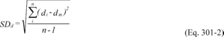 Where:
SDd = Standard deviation of the differences of the paired samples.
di = Difference between the results of the i th replicate pair of
samples. dm = Mean of the paired sample differences. n = Total
number of paired samples.
Where:
SDd = Standard deviation of the differences of the paired samples.
di = Difference between the results of the i th replicate pair of
samples. dm = Mean of the paired sample differences. n = Total
number of paired samples.
7.4.2 T Test. Test the difference in the results for statistical significance by calculating the t-statistic and determining if the mean of the differences between the results at the minimum storage duration and the results after the maximum storage duration is significant at the 95 percent confidence level and n-1 degrees of freedom. Calculate the value of the t-statistic using Equation 301-3.
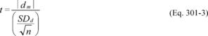 Where:
t = t-statistic. dm = The mean of the paired sample
differences. SDd = Standard deviation of the differences of the
paired samples. n = Total number of paired samples.
Where:
t = t-statistic. dm = The mean of the paired sample
differences. SDd = Standard deviation of the differences of the
paired samples. n = Total number of paired samples.
Compare the calculated t-statistic with the critical value of the t-statistic from Table 301-3 of this method. If the calculated t-value is less than the critical value, the difference is not statistically significant. Therefore, the sampling, analysis, and sample storage procedures ensure stability, and you may submit a request for validation of the candidate test method. If the calculated t-value is greater than the critical value, the difference is statistically significant, and you must repeat the procedures in Section 7.2 or 7.3 of this method with new samples using a shorter proposed maximum storage duration or improved handling and storage procedures.
Determination of Bias and Precision 8.0 What are the requirements for bias?You must determine bias by comparing the results of sampling and analysis using the candidate test method against a reference value. The bias must be no more than ±10 percent for the candidate test method to be considered for application to multiple sources. A candidate test method with a bias greater than ±10 percent and less than or equal to ±30 percent can only be applied on a source-specific basis at the facility at which the validation testing was conducted. In this case, you must use a correction factor for all data collected in the future using the candidate test method. If the bias is more than ±30 percent, the candidate test method is unacceptable.
9.0 What are the requirements for precision?You may use a paired sampling system or a quadruplicate sampling system to establish precision for isotopic spiking. You must use a quadruplicate sampling system to establish precision for analyte spiking or when comparing a candidate test method to a validated method. If you are using analyte spiking or isotopic spiking, the precision, expressed as the relative standard deviation (RSD) of the candidate test method, must be less than or equal to 20 percent. If you are comparing the candidate test method to a validated test method, the candidate test method must be at least as precise as the validated method as determined by an F test (see Section 11.2.2 of this method).
10.0 What calculations must I perform for isotopic spiking?You must analyze the bias, RSD, precision, and data acceptance for isotopic spiking tests according to the provisions in Sections 10.1 through 10.4 of this method.
10.1 Numerical Bias. Calculate the numerical value of the bias using the results from the analysis of the isotopic spike in the field samples and the calculated value of the spike according to Equation 301-4.
 Where: B
= Bias at the spike level. Sm = Mean of the measured values of the
isotopically-labeled analyte in the samples. CS = Calculated value
of the isotopically-labeled spike level.
Where: B
= Bias at the spike level. Sm = Mean of the measured values of the
isotopically-labeled analyte in the samples. CS = Calculated value
of the isotopically-labeled spike level.
10.2 Standard Deviation. Calculate the standard deviation of the Si values according to Equation 301-5.
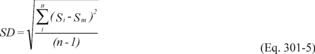 Where: SD
= Standard deviation of the candidate test method. Si = Measured
value of the isotopically-labeled analyte in the i th field sample.
Sm = Mean of the measured values of the isotopically-labeled
analyte in the samples. n = Number of isotopically-spiked samples.
Where: SD
= Standard deviation of the candidate test method. Si = Measured
value of the isotopically-labeled analyte in the i th field sample.
Sm = Mean of the measured values of the isotopically-labeled
analyte in the samples. n = Number of isotopically-spiked samples.
10.3 T Test. Test the bias for statistical significance by calculating the t-statistic using Equation 301-6. Use the standard deviation determined in Section 10.2 of this method and the numerical bias determined in Section 10.1 of this method.
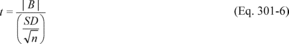 Where: t
= Calculated t-statistic. B = Bias at the spike level. SD =
Standard deviation of the candidate test method. n = Number of
isotopically spike samples.
Where: t
= Calculated t-statistic. B = Bias at the spike level. SD =
Standard deviation of the candidate test method. n = Number of
isotopically spike samples.
Compare the calculated t-value with the critical value of the two-sided t-distribution at the 95 percent confidence level and n-1 degrees of freedom (see Table 301-3 of this method). When you conduct isotopic spiking according to the procedures specified in Sections 6.1 and 6.3 of this method as required, this critical value is 2.201 for 11 degrees of freedom. If the calculated t-value is less than or equal to the critical value, the bias is not statistically significant, and the bias of the candidate test method is acceptable. If the calculated t-value is greater than the critical value, the bias is statistically significant, and you must evaluate the relative magnitude of the bias using Equation 301-7.
 Where: BR
= Relative bias. B = Bias at the spike level. CS = Calculated value
of the spike level.
Where: BR
= Relative bias. B = Bias at the spike level. CS = Calculated value
of the spike level.
If the relative bias is less than or equal to 10 percent, the bias of the candidate test method is acceptable for use at multiple sources. If the relative bias is greater than 10 percent but less than or equal to 30 percent, and if you correct all data collected with the candidate test method in the future for bias using the source-specific correction factor determined in Equation 301-8, the candidate test method is acceptable only for application to the source at which the validation testing was conducted and may not be applied to any other sites. If either of the preceding two cases applies, you may continue to evaluate the candidate test method by calculating its precision. If not, the candidate test method does not meet the requirements of Method 301.
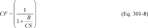 Where: CF
= Source-specific bias correction factor. B = Bias at the spike
level. CS = Calculated value of the spike level.
Where: CF
= Source-specific bias correction factor. B = Bias at the spike
level. CS = Calculated value of the spike level.
If the CF is outside the range of 0.70 to 1.30, the data and method are considered unacceptable.
10.4 Precision. Calculate the RSD according to Equation 301-9.
 Where:
RSD = Relative standard deviation of the candidate test method. SD
= Standard deviation of the candidate test method calculated in
Equation 301-5. Sm = Mean of the measured values of the spike
samples.
Where:
RSD = Relative standard deviation of the candidate test method. SD
= Standard deviation of the candidate test method calculated in
Equation 301-5. Sm = Mean of the measured values of the spike
samples.
The data and candidate test method are unacceptable if the RSD is greater than 20 percent.
11.0 What calculations must I perform for comparison with a validated method?If you are comparing a candidate test method to a validated method, then you must analyze the data according to the provisions in this section. If the data from the candidate test method fail either the bias or precision test, the data and the candidate test method are unacceptable. If the Administrator determines that the affected source has highly variable emission rates, the Administrator may require additional precision checks.
11.1 Bias Analysis. Test the bias for statistical significance at the 95 percent confidence level by calculating the t-statistic.
11.1.1 Bias. Determine the bias, which is defined as the mean of the differences between the candidate test method and the validated method (dm). Calculate di according to Equation 301-10.
 Where: di
= Difference in measured value between the candidate test method
and the validated method for each quadruplicate sampling train. V1i
= First measured value with the validated method in the ith
quadruplicate sampling train. V2i = Second measured value with the
validated method in the ith quadruplicate sampling train. P1i =
First measured value with the candidate test method in the ith
quadruplicate sampling train. P2i = Second measured value with the
candidate test method in the ith quadruplicate sampling train.
Where: di
= Difference in measured value between the candidate test method
and the validated method for each quadruplicate sampling train. V1i
= First measured value with the validated method in the ith
quadruplicate sampling train. V2i = Second measured value with the
validated method in the ith quadruplicate sampling train. P1i =
First measured value with the candidate test method in the ith
quadruplicate sampling train. P2i = Second measured value with the
candidate test method in the ith quadruplicate sampling train.
Calculate the numerical value of the bias using Equation 301-11.
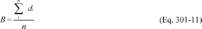 Where: B
= Numerical bias. di = Difference between the candidate test method
and the validated method for the ith quadruplicate sampling train.
n = Number of quadruplicate sampling trains.
Where: B
= Numerical bias. di = Difference between the candidate test method
and the validated method for the ith quadruplicate sampling train.
n = Number of quadruplicate sampling trains.
11.1.2 Standard Deviation of the Differences. Calculate the standard deviation of the differences, SDd, using Equation 301-12.
 Where:
SDd = Standard deviation of the differences between the candidate
test method and the validated method. di = Difference in measured
value between the candidate test method and the validated method
for each quadruplicate sampling train. dm = Mean of the
differences, di, between the candidate test method and the
validated method. n = Number of quadruplicate sampling trains.
Where:
SDd = Standard deviation of the differences between the candidate
test method and the validated method. di = Difference in measured
value between the candidate test method and the validated method
for each quadruplicate sampling train. dm = Mean of the
differences, di, between the candidate test method and the
validated method. n = Number of quadruplicate sampling trains.
11.1.3 T Test. Calculate the t-statistic using Equation 301-13.
 Where:
t = Calculated t-statistic. dm = The mean of the
differences, di, between the candidate test method and the
validated method. SDd = Standard deviation of the differences
between the candidate test method and the validated method. n =
Number of quadruplicate sampling trains.
Where:
t = Calculated t-statistic. dm = The mean of the
differences, di, between the candidate test method and the
validated method. SDd = Standard deviation of the differences
between the candidate test method and the validated method. n =
Number of quadruplicate sampling trains.
For the procedure comparing a candidate test method to a validated test method listed in Table 301-1 of this method, n equals six. Compare the calculated t-statistic with the critical value of the t-statistic, and determine if the bias is significant at the 95 percent confidence level (see Table 301-3 of this method). When six runs are conducted, as specified in Table 301-1 of this method, the critical value of the t-statistic is 2.571 for five degrees of freedom. If the calculated t-value is less than or equal to the critical value, the bias is not statistically significant and the data are acceptable. If the calculated t-value is greater than the critical value, the bias is statistically significant, and you must evaluate the magnitude of the relative bias using Equation 301-14.
 Where: BR
= Relative bias. B = Bias as calculated in Equation 301-11. VS =
Mean of measured values from the validated method.
Where: BR
= Relative bias. B = Bias as calculated in Equation 301-11. VS =
Mean of measured values from the validated method.
If the relative bias is less than or equal to 10 percent, the bias of the candidate test method is acceptable. On a source-specific basis, if the relative bias is greater than 10 percent but less than or equal to 30 percent, and if you correct all data collected in the future with the candidate test method for the bias using the correction factor, CF, determined in Equation 301-8 (using VS for CS), the bias of the candidate test method is acceptable for application to the source at which the validation testing was conducted. If either of the preceding two cases applies, you may continue to evaluate the candidate test method by calculating its precision. If not, the candidate test method does not meet the requirements of Method 301.
11.2 Precision. Compare the estimated variance (or standard deviation) of the candidate test method to that of the validated test method according to Sections 11.2.1 and 11.2.2 of this method. If a significant difference is determined using the F test, the candidate test method and the results are rejected. If the F test does not show a significant difference, then the candidate test method has acceptable precision.
11.2.1 Candidate Test Method Variance. Calculate the estimated variance of the candidate test method according to Equation 301-15.
 Where: p
= Estimated variance of the candidate test method. di = The
difference between the i th pair of samples collected with the
candidate test method in a single quadruplicate train. n = Total
number of paired samples (quadruplicate trains).
Where: p
= Estimated variance of the candidate test method. di = The
difference between the i th pair of samples collected with the
candidate test method in a single quadruplicate train. n = Total
number of paired samples (quadruplicate trains).
Calculate the estimated variance of the validated test method according to Equation 301-16.
 Where: v
= Estimated variance of the validated test method. di = The
difference between the i th pair of samples collected with the
validated test method in a single quadruplicate train. n = Total
number of paired samples (quadruplicate trains).
Where: v
= Estimated variance of the validated test method. di = The
difference between the i th pair of samples collected with the
validated test method in a single quadruplicate train. n = Total
number of paired samples (quadruplicate trains).
11.2.2 The F test. Determine if the estimated variance of the candidate test method is greater than that of the validated method by calculating the F-value using Equation 301-17.
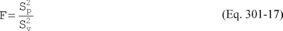 Where: F
= Calculated F value. p = The estimated variance of the candidate
test method. v = The estimated variance of the validated method.
Where: F
= Calculated F value. p = The estimated variance of the candidate
test method. v = The estimated variance of the validated method.
Compare the calculated F value with the one-sided confidence level for F from Table 301-4 of this method. The upper one-sided confidence level of 95 percent for F(6,6) is 4.28 when the procedure specified in Table 301-1 of this method for quadruplicate sampling trains is followed. If the calculated F value is greater than the critical F value, the difference in precision is significant, and the data and the candidate test method are unacceptable.
12.0 What calculations must I perform for analyte spiking?You must analyze the data for analyte spike testing according to this section.
12.1 Bias Analysis. Test the bias for statistical significance at the 95 percent confidence level by calculating the t-statistic.
12.1.1 Bias. Determine the bias, which is defined as the mean of the differences between the spiked samples and the unspiked samples in each quadruplicate sampling train minus the spiked amount, using Equation 301-18.
 Where: di
= Difference between the spiked samples and unspiked samples in
each quadruplicate sampling train minus the spiked amount. S1i =
Measured value of the first spiked sample in the i th quadruplicate
sampling train. S2i = Measured value of the second spiked sample in
the i th quadruplicate sampling train. M1i = Measured value of the
first unspiked sample in the i th quadruplicate sampling train. M2i
= Measured value of the second unspiked sample in the i th
quadruplicate sampling train. CS = Calculated value of the spike
level.
Where: di
= Difference between the spiked samples and unspiked samples in
each quadruplicate sampling train minus the spiked amount. S1i =
Measured value of the first spiked sample in the i th quadruplicate
sampling train. S2i = Measured value of the second spiked sample in
the i th quadruplicate sampling train. M1i = Measured value of the
first unspiked sample in the i th quadruplicate sampling train. M2i
= Measured value of the second unspiked sample in the i th
quadruplicate sampling train. CS = Calculated value of the spike
level.
Calculate the numerical value of the bias using Equation 301-19.
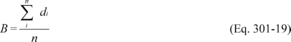 Where: B
= Numerical value of the bias. di = Difference between the spiked
samples and unspiked samples in each quadruplicate sampling train
minus the spiked amount. n = Number of quadruplicate sampling
trains.
Where: B
= Numerical value of the bias. di = Difference between the spiked
samples and unspiked samples in each quadruplicate sampling train
minus the spiked amount. n = Number of quadruplicate sampling
trains.
12.1.2 Standard Deviation of the Differences. Calculate the standard deviation of the differences using Equation 301-20.
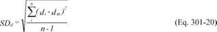 Where:
SDd = Standard deviation of the differences of paired samples. di =
Difference between the spiked samples and unspiked samples in each
quadruplicate sampling train minus the spiked amount. dm = The mean
of the differences, di, between the spiked samples and unspiked
samples. n = Total number of quadruplicate sampling trains.
Where:
SDd = Standard deviation of the differences of paired samples. di =
Difference between the spiked samples and unspiked samples in each
quadruplicate sampling train minus the spiked amount. dm = The mean
of the differences, di, between the spiked samples and unspiked
samples. n = Total number of quadruplicate sampling trains.
12.1.3 T Test. Calculate the t-statistic using Equation 301-21, where n is the total number of test sample differences (di). For the quadruplicate sampling system procedure in Table 301-1 of this method, n equals six.
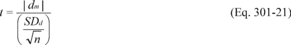 Where: t
= Calculated t-statistic. dm = Mean of the difference, di,
between the spiked samples and unspiked samples. SDd = Standard
deviation of the differences of paired samples. n = Number of
quadruplicate sampling trains.
Where: t
= Calculated t-statistic. dm = Mean of the difference, di,
between the spiked samples and unspiked samples. SDd = Standard
deviation of the differences of paired samples. n = Number of
quadruplicate sampling trains.
Compare the calculated t-statistic with the critical value of the t-statistic, and determine if the bias is significant at the 95 percent confidence level. When six quadruplicate runs are conducted, as specified in Table 301-1 of this method, the 2-sided confidence level critical value is 2.571 for the five degrees of freedom. If the calculated t-value is less than the critical value, the bias is not statistically significant and the data are acceptable. If the calculated t-value is greater than the critical value, the bias is statistically significant and you must evaluate the magnitude of the relative bias using Equation 301-22.
 Where: BR
= Relative bias. B = Bias at the spike level from Equation 301-19.
CS = Calculated value at the spike level.
Where: BR
= Relative bias. B = Bias at the spike level from Equation 301-19.
CS = Calculated value at the spike level.
If the relative bias is less than or equal to 10 percent, the bias of the candidate test method is acceptable. On a source-specific basis, if the relative bias is greater than 10 percent but less than or equal to 30 percent, and if you correct all data collected with the candidate test method in the future for the magnitude of the bias using Equation 301-8, the bias of the candidate test method is acceptable for application to the tested source at which the validation testing was conducted. Proceed to evaluate precision of the candidate test method.
12.2 Precision. Calculate the standard deviation using Equation 301-23.
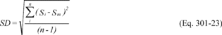 Where: SD
= Standard deviation of the candidate test method. Si = Measured
value of the analyte in the i th spiked sample. Sm = Mean of the
measured values of the analyte in all the spiked samples. n =
Number of spiked samples.
Where: SD
= Standard deviation of the candidate test method. Si = Measured
value of the analyte in the i th spiked sample. Sm = Mean of the
measured values of the analyte in all the spiked samples. n =
Number of spiked samples.
Calculate the RSD of the candidate test method using Equation 301-9, where SD and Sm are the values from Equation 301-23. The data and candidate test method are unacceptable if the RSD is greater than 20 percent.
13.0 How do I conduct tests at similar sources?If the Administrator has approved the use of an alternative test method to a test method required in 40 CFR part 59, 60, 61, 63, or 65 for an affected source, and you would like to apply the alternative test method to a similar source, then you must petition the Administrator as described in Section 17.1.1 of this method.
Optional Requirements 14.0 How do I use and conduct ruggedness testing?Ruggedness testing is an optional requirement for validation of a candidate test method that is intended for the source where the validation testing was conducted. Ruggedness testing is required for validation of a candidate test method intended to be used at multiple sources. If you want to use a validated test method at a concentration that is different from the concentration in the applicable emission limitation under 40 CFR part 59, 60, 61, 63, or 65, or for a source category that is different from the source category that the test method specifies, then you must conduct ruggedness testing according to the procedures in Reference 18.16 of Section 18.0 of this method and submit a request for a waiver for conducting Method 301 at that different source category according to Section 17.1.1 of this method.
Ruggedness testing is a study that can be conducted in the laboratory or the field to determine the sensitivity of a method to parameters such as analyte concentration, sample collection rate, interferent concentration, collection medium temperature, and sample recovery temperature. You conduct ruggedness testing by changing several variables simultaneously instead of changing one variable at a time. For example, you can determine the effect of seven variables in only eight experiments. (W.J. Youden, Statistical Manual of the Association of Official Analytical Chemists, Association of Official Analytical Chemists, Washington, DC, 1975, pp. 33-36).
15.0 How do I determine the Limit of Detection for the candidate test method?Determination of the Limit of Detection (LOD) as specified in Sections 15.1 and 15.2 of this method is required for source-specific method validation and validation of a candidate test method intended to be used for multiple sources.
15.1 Limit of Detection. The LOD is the minimum concentration of a substance that can be measured and reported with 99 percent confidence that the analyte concentration is greater than zero. For this protocol, the LOD is defined as three times the standard deviation, So, at the blank level.
15.2 Purpose. The LOD establishes the lower detection limit of the candidate test method. You must calculate the LOD using the applicable procedures found in Table 301-5 of this method. For candidate test methods that collect the analyte in a sample matrix prior to an analytical measurement, you must determine the LOD using Procedure I in Table 301-5 of this method by calculating a method detection limit (MDL) as described in 40 CFR part 136, appendix B. For the purposes of this section, the LOD is equivalent to the calculated MDL. For radiochemical methods, use the Multi-Agency Radiological Laboratory Analytical Protocols (MARLAP) Manual (i.e., use the minimum detectable concentration (MDC) and not the LOD) available at https://www.epa.gov/radiation/marlap-manual-and-supporting-documents.
Other Requirements and Information 16.0 How do I apply for approval to use a candidate test method?16.1 Submitting Requests. You must request to use a candidate test method according to the procedures in § 63.7(f) or similar sections of 40 CFR parts 59, 60, 61, and 65 (§ 59.104, § 59.406, § 60.8(b), § 61.13(h)(1)(ii), or § 65.158(a)(2)(iii)). You cannot use a candidate test method to meet any requirement under these parts until the Administrator has approved your request. The request must include a field validation report containing the information in Section 16.2 of this method. You must submit the request to the Group Leader, Measurement Technology Group, U.S. Environmental Protection Agency, E143-02, Research Triangle Park, NC 27711.
16.2 Field Validation Report. The field validation report must contain the information in Sections 16.2.1 through 16.2.8 of this method.
16.2.1 Regulatory objectives for the testing, including a description of the reasons for the test, applicable emission limits, and a description of the source.
16.2.2 Summary of the results and calculations shown in Sections 6.0 through 16.0 of this method, as applicable.
16.2.3 Reference material certification and value(s).
16.2.4 Discussion of laboratory evaluations.
16.2.5 Discussion of field sampling.
16.2.6 Discussion of sample preparation and analysis.
16.2.7 Storage times of samples (and extracts, if applicable).
16.2.8 Reasons for eliminating any results.
17.0 How do I request a waiver?17.1 Conditions for Waivers. If you meet one of the criteria in Section 17.1.1 or 17.1.2 of this method, the Administrator may waive the requirement to use the procedures in this method to validate an alternative or other candidate test method. In addition, if the EPA currently recognizes an appropriate test method or considers the candidate test method to be satisfactory for a particular source, the Administrator may waive the use of this protocol or may specify a less rigorous validation procedure.
17.1.1 Similar Sources. If the alternative or other candidate test method that you want to use was validated for source-specific application at another source and you can demonstrate to the Administrator's satisfaction that your affected source is similar to that validated source, then the Administrator may waive the requirement for you to validate the alternative or other candidate test method. One procedure you may use to demonstrate the applicability of the method to your affected source is to conduct a ruggedness test as described in Section 14.0 of this method.
17.1.2 Documented Methods. If the bias, precision, LOD, or ruggedness of the alternative or other candidate test method that you are proposing have been demonstrated through laboratory tests or protocols different from this method, and you can demonstrate to the Administrator's satisfaction that the bias, precision, LOD, or ruggedness apply to your application, then the Administrator may waive the requirement to use this method or to use part of this method.
17.2 Submitting Applications for Waivers. You must sign and submit each request for a waiver from the requirements in this method in writing. The request must be submitted to the Group Leader, Measurement Technology Group, U.S. Environmental Protection Agency, E143-02, Research Triangle Park, NC 27711.
17.3 Information Application for Waiver. The request for a waiver must contain a thorough description of the candidate test method, the intended application, and results of any validation or other supporting documents. The request for a waiver must contain, at a minimum, the information in Sections 17.3.1 through 17.3.4 of this method. The Administrator may request additional information if necessary to determine whether this method can be waived for a particular application.
17.3.1 A Clearly Written Test Method. The candidate test method should be written preferably in the format of 40 CFR part 60, appendix A, Test Methods. Additionally, the candidate test must include an applicability statement, concentration range, precision, bias (accuracy), and minimum and maximum storage durations in which samples must be analyzed.
17.3.2 Summaries of Previous Validation Tests or Other Supporting Documents. If you use a different procedure from that described in this method, you must submit documents substantiating the bias and precision values to the Administrator's satisfaction.
17.3.3 Ruggedness Testing Results. You must submit results of ruggedness testing conducted according to Section 14.0 of this method, sample stability conducted according to Section 7.0 of this method, and detection limits conducted according to Section 15.0 of this method, as applicable. For example, you would not need to submit ruggedness testing results if you will be using the method at the same affected source and level at which it was validated.
17.3.4 Applicability Statement and Basis for Waiver Approval. Discussion of the applicability statement and basis for approval of the waiver. This discussion should address as applicable the following: applicable regulation, emission standards, effluent characteristics, and process operations.
18.0 Where can I find additional information?You can find additional information in the references in Sections 18.1 through 18.18 of this method.
18.1 Albritton, J.R., G.B. Howe, S.B. Tompkins, R.K.M. Jayanty, and C.E. Decker. 1989. Stability of Parts-Per-Million Organic Cylinder Gases and Results of Source Test Analysis Audits, Status Report No. 11. Environmental Protection Agency Contract 68-02-4125. Research Triangle Institute, Research Triangle Park, NC. September. 18.2 ASTM Standard E 1169-89 (current version), “Standard Guide for Conducting Ruggedness Tests,” available from ASTM, 100 Barr Harbor Drive, West Conshohoken, PA 19428. 18.3 DeWees, W.G., P.M. Grohse, K.K. Luk, and F.E. Butler. 1989. Laboratory and Field Evaluation of a Methodology for Speciating Nickel Emissions from Stationary Sources. EPA Contract 68-02-4442. Prepared for Atmospheric Research and Environmental Assessment Laboratory, Office of Research and Development, U.S. Environmental Protection Agency, Research Triangle Park, NC 27711. January. 18.4 International Conference on Harmonization of Technical Requirements for the Registration of Pharmaceuticals for Human Use, ICH-Q2A, “Text on Validation of Analytical Procedures,” 60 FR 11260 (March 1995). 18.5 International Conference on Harmonization of Technical Requirements for the Registration of Pharmaceuticals for Human Use, ICH-Q2b, “Validation of Analytical Procedures: Methodology,” 62 FR 27464 (May 1997). 18.6 Keith, L.H., W. Crummer, J. Deegan Jr., R.A. Libby, J.K. Taylor, and G. Wentler. 1983. Principles of Environmental Analysis. American Chemical Society, Washington, DC. 18.7 Maxwell, E.A. 1974. Estimating variances from one or two measurements on each sample. Amer. Statistician 28:96-97. 18.8 Midgett, M.R. 1977. How EPA Validates NSPS Methodology. Environ. Sci. & Technol. 11(7):655-659. 18.9 Mitchell, W.J., and M.R. Midgett. 1976. Means to evaluate performance of stationary source test methods. Environ. Sci. & Technol. 10:85-88. 18.10 Plackett, R.L., and J.P. Burman. 1946. The design of optimum multifactorial experiments. Biometrika, 33:305. 18.11 Taylor, J.K. 1987. Quality Assurance of Chemical Measurements. Lewis Publishers, Inc., pp. 79-81. 18.12 U.S. Environmental Protection Agency. 1978. Quality Assurance Handbook for Air Pollution Measurement Systems: Volume III. Stationary Source Specific Methods. Publication No. EPA-600/4-77-027b. Office of Research and Development Publications, 26 West St. Clair St., Cincinnati, OH 45268. 18.13 U.S. Environmental Protection Agency. 1981. A Procedure for Establishing Traceability of Gas Mixtures to Certain National Bureau of Standards Standard Reference Materials. Publication No. EPA-600/7-81-010. Available from the U.S. EPA, Quality Assurance Division (MD-77), Research Triangle Park, NC 27711. 18.14 U.S. Environmental Protection Agency. 1991. Protocol for The Field Validation of Emission Concentrations from Stationary Sources. Publication No. 450/4-90-015. Available from the U.S. EPA, Emission Measurement Technical Information Center, Technical Support Division (MD-14), Research Triangle Park, NC 27711. 18.15 Wernimont, G.T., “Use of Statistics to Develop and Evaluate Analytical Methods,” AOAC, 1111 North 19th Street, Suite 210, Arlington, VA 22209, USA, 78-82 (1987). 18.16 Youden, W.J. Statistical techniques for collaborative tests. In: Statistical Manual of the Association of Official Analytical Chemists, Association of Official Analytical Chemists, Washington, DC, 1975, pp. 33-36. 18.17 NIST/SEMATECH (current version), “e-Handbook of Statistical Methods,” available from NIST, http://www.itl.nist.gov/div898/handbook/. 18.18 Statistical Table, http://www.math.usask.ca/∼szafron/Stats244/f_table_0_05.pdf. 19.0 Tables.Table 301-1 - Sampling Procedures
If you are . . . |
You must collect . . . |
|---|---|
| Comparing the candidate test method against a validated method | A total of 24 samples using a quadruplicate sampling system (a total of six sets of replicate samples). In each quadruplicate sample set, you must use the validated test method to collect and analyze half of the samples. |
| Using isotopic spiking (can only be used with methods capable of measurement of multiple isotopes simultaneously) | A total of 12 samples, all of which are spiked with isotopically-labeled analyte. You may collect the samples either by obtaining six sets of paired samples or three sets of quadruplicate samples. |
| Using analyte spiking | A total of 24 samples using the quadruplicate sampling system (a total of six sets of replicate samples - two spiked and two unspiked). |
Table 301-2 - Storage and Sampling Procedures for Stack Test Emissions
If you are . . . |
With . . . |
Then you must . . . |
|---|---|---|
| Using isotopic or analyte spiking procedures | Sample container (bag or canister) or impinger sampling systems that are not subject to dilution or other preparation steps | Analyze six of the samples within 7 days and then analyze the same six samples at the proposed maximum storage duration or 2 weeks after the initial analysis. |
| Sorbent and impinger sampling systems that require extraction or digestion | Extract or digest six of the samples within 7 days and extract or digest six other samples at the proposed maximum storage duration or 2 weeks after the first extraction or digestion. Analyze an aliquot of the first six extracts (digestates) within 7 days and proposed maximum storage duration or 2 weeks after the initial analysis. This will allow analysis of extract storage impacts. | |
| Sorbent sampling systems that require thermal desorption | Analyze six samples within 7 days. Analyze another set of six samples at the proposed maximum storage time or within 2 weeks of the initial analysis. | |
| Comparing a candidate test method against a validated test method | Sample container (bag or canister) or impinger sampling systems that are not subject to dilution or other preparation steps | Analyze at least six of the candidate test method samples within 7 days and then analyze the same six samples at the proposed maximum storage duration or within 2 weeks of the initial analysis. |
| Sorbent and impinger sampling systems that require extraction or digestion | Extract or digest six of the candidate test method samples within 7 days and extract or digest six other samples at the proposed maximum storage duration or within 2 weeks of the first extraction or digestion. Analyze an aliquot of the first six extracts (digestates) within 7 days and an aliquot at the proposed maximum storage durations or within 2 weeks of the initial analysis. This will allow analysis of extract storage impacts. | |
| Sorbent systems that require thermal desorption | Analyze six samples within 7 days. Analyze another set of six samples at the proposed maximum storage duration or within 2 weeks of the initial analysis. |
Table 301-3 - Critical Values of t for the Two-Tailed 95 Percent Confidence Limit 1
| Degrees of freedom | t95 |
|---|---|
| 1 | 12.706 |
| 2 | 4.303 |
| 3 | 3.182 |
| 4 | 2.776 |
| 5 | 2.571 |
| 6 | 2.447 |
| 7 | 2.365 |
| 8 | 2.306 |
| 9 | 2.262 |
| 10 | 2.228 |
| 11 | 2.201 |
| 12 | 2.179 |
| 13 | 2.160 |
| 14 | 2.145 |
| 15 | 2.131 |
| 16 | 2.120 |
| 17 | 2.110 |
| 18 | 2.101 |
| 19 | 2.093 |
| 20 | 2.086 |
1 Adapted from Reference 18.17 in section 18.0.
Table 301-4 - Upper Critical Values of the F Distribution for the 95 Percent Confidence Limit 1
| Numerator (k1) and denominator (k2) degrees of freedom | F{F>F.05(k1,k2)} |
|---|---|
| 1,1 | 161.40 |
| 2,2 | 19.00 |
| 3,3 | 9.28 |
| 4,4 | 6.39 |
| 5,5 | 5.05 |
| 6,6 | 4.28 |
| 7,7 | 3.79 |
| 8,8 | 3.44 |
| 9,9 | 3.18 |
| 10,10 | 2.98 |
| 11,11 | 2.82 |
| 12,12 | 2.69 |
| 13,13 | 2.58 |
| 14,14 | 2.48 |
| 15,15 | 2.40 |
| 16,16 | 2.33 |
| 17,17 | 2.27 |
| 18,18 | 2.22 |
| 19,19 | 2.17 |
| 20,20 | 2.12 |
1 Adapted from References 18.17 and 18.18 in section 18.0.
Table 301-5 - Procedures for Estimating So
| If the estimated LOD (LOD1, expected approximate LOD concentration level) is no more than twice the calculated LOD or an analyte in a sample matrix was collected prior to an analytical measurement, use Procedure I as follows | If the estimated LOD (LOD1, expected approximate LOD concentration level) is greater than twice the calculated LOD, use Procedure II as follows. |
| Procedure I: | Procedure II: |
| Determine the LOD by calculating a method detection limit (MDL) as described in 40 CFR part 136, appendix B | Prepare two additional standards (LOD2 and LOD3) at concentration levels lower than the standard used in Procedure I (LOD1). |
| Sample and analyze each of these standards (LOD2 and LOD3) at least seven times. | |
| Calculate the standard deviation (S2 and S3) for each concentration level. | |
| Plot the standard deviations of the three test standards (S1, S2 and S3) as a function of concentration. | |
| Draw a best-fit straight line through the data points and extrapolate to zero concentration. The standard deviation at zero concentration is So. | |
| Calculate the LOD0 (referred to as the calculated LOD) as 3 times So. |
This method is not inclusive with respect to observer certification. Some material is incorporated by reference from other methods in appendix A to 40 CFR part 60. Therefore, to obtain reliable results, persons using this method should have a thorough knowledge of Method 9.
1.0 Scope and Application1.1 Applicability. This method is applicable for the determination of visible emissions (VE) from the following by-product coke oven battery sources: charging systems during charging; doors, topside port lids, and offtake systems on operating coke ovens; and collecting mains. This method is also applicable for qualifying observers for visually determining the presence of VE. In order for the test method results to be indicative of plant performance, the time of day of the run should vary.
2.0 Summary of Method2.1 A certified observer visually determines the VE from coke oven battery sources. Certification procedures are presented. This method does not require that opacity of emissions be determined or that magnitude be differentiated.
3.0 Definitions3.1 Bench means the platform structure in front of the oven doors.
3.2 By-product Coke Oven Battery means a source consisting of a group of ovens connected by common walls, where coal undergoes destructive distillation under positive pressure to produce coke and coke oven gas, from which by-products are recovered.
3.3 Charge or charging period means the period of time that commences when coal begins to flow into an oven through a topside port and ends when the last charging port is recapped.
3.4 Charging system means an apparatus used to charge coal to a coke oven (e.g., a larry car for wet coal charging systems).
3.5 Coke oven door means each end enclosure on the push side and the coking side of an oven. The chuck, or leveler-bar, door is considered part of the push side door. The coke oven door area includes the entire area on the vertical face of a coke oven between the bench and the top of the battery between two adjacent buck stays.
3.6 Coke side means the side of a battery from which the coke is discharged from ovens at the end of the coking cycle.
3.7 Collecting main means any apparatus that is connected to one or more offtake systems and that provides a passage for conveying gases under positive pressure from the by-product coke oven battery to the by-product recovery system.
3.8 Consecutive charges means charges observed successively, excluding any charge during which the observer's view of the charging system or topside ports is obscured.
3.9 Damper-off means to close off the gas passage between the coke oven and the collecting main, with no flow of raw coke oven gas from the collecting main into the oven or into the oven's offtake system(s).
3.10 Decarbonization period means the period of time for combusting oven carbon that commences when the oven lids are removed from an empty oven or when standpipe caps of an oven are opened. The period ends with the initiation of the next charging period for that oven.
3.11 Larry car means an apparatus used to charge coal to a coke oven with a wet coal charging system.
3.12 Log average means logarithmic average as calculated in Section 12.4.
3.13 Offtake system means any individual oven apparatus that is stationary and provides a passage for gases from an oven to a coke oven battery collecting main or to another oven. Offtake system components include the standpipe and standpipe caps, goosenecks, stationary jumper pipes, mini-standpipes, and standpipe and gooseneck connections.
3.14 Operating oven means any oven not out of operation for rebuild or maintenance work extensive enough to require the oven to be skipped in the charging sequence.
3.15 Oven means a chamber in the coke oven battery in which coal undergoes destructive distillation to produce coke.
3.16 Push side means the side of the battery from which the coke is pushed from ovens at the end of the coking cycle.
3.17 Run means the observation of visible emissions from topside port lids, offtake systems, coke oven doors, or the charging of a single oven in accordance with this method.
3.18 Shed means an enclosure that covers the side of the coke oven battery, captures emissions from pushing operations and from leaking coke oven doors on the coke side or push side of the coke oven battery, and routes the emissions to a control device or system.
3.19 Standpipe cap means An apparatus used to cover the opening in the gooseneck of an offtake system.
3.20 Topside port lid means a cover, removed during charging or decarbonizing, that is placed over the opening through which coal can be charged into the oven of a by-product coke oven battery.
3.21 Traverse time means accumulated time for a traverse as measured by a stopwatch. Traverse time includes time to stop and write down oven numbers but excludes time waiting for obstructions of view to clear or for time to walk around obstacles.
3.22 Visible Emissions or VE means any emission seen by the unaided (except for corrective lenses) eye, excluding steam or condensing water.
4.0 Interferences [Reserved] 5.0 Safety5.1 Disclaimer. This method may involve hazardous materials, operations, and equipment. This test method may not address all of the safety problems associated with its use. It is the responsibility of the user of this test method to establish appropriate safety and health practices and determine the applicability of regulatory limitations prior to performing this test method.
5.2 Safety Training. Because coke oven batteries have hazardous environments, the training materials and the field training (section 10.0) shall cover the precautions required to address health and safety hazards.
6.0 Equipment and Supplies [Reserved] 7.0 Reagents and Standards [Reserved] 8.0 Sample Collection, Preservation, Transport, and Storage [Reserved] 9.0 Quality Control [Reserved] 10.0 Calibration and StandardizationObserver certification and training requirements are as follows:
10.1 Certification Procedures. This method requires only the determination of whether VE occur and does not require the determination of opacity levels; therefore, observer certification according to Method 9 in appendix A to part 60 of this chapter is not required to obtain certification under this method. However, in order to receive Method 303 observer certification, the first-time observer (trainee) shall have attended the lecture portion of the Method 9 certification course. In addition, the trainee shall successfully complete the Method 303 training course, satisfy the field observation requirement, and demonstrate adequate performance and sufficient knowledge of Method 303. The Method 303 training provider and course shall be approved by the Administrator and shall consist of classroom instruction, field training, and a proficiency test. In order to apply for approval as a Method 303 training provider, an applicant must submit their credentials and the details of their Method 303 training course to Group Leader, Measurement Technology Group (E143-02), Office of Air Quality Planning and Standards, U.S. Environmental Protection Agency, Research Triangle Park, NC 27711. Those details should include, at a minimum:
(a) A detailed list of the provider's credentials.
(b) An outline of the classroom and the field portions of the class.
(c) Copies of the written training and lecture materials, to include:
(1) The classroom audio-visual presentation(s).
(2) A classroom course manual with instructional text, practice questions and problems for each of the elements of the Method 303 inspection (i.e., charging, doors, lids and offtakes, and collecting mains). A copy of Method 303 and any related guidance documents should be included as appendices.
(3) A copy of the Method 303 demonstration video, if not using the one available at: http://www3.epa.gov/ttn/emc/methods/method303trainingvideo.mp4.
(4) Multiple-choice certification tests, with questions sufficient to demonstrate knowledge of the method, as follows: One (1) Initial certification test and three (3) third-year recertification tests (the questions on any one recertification test must be at least 25 percent different from those on the other recertification tests).
(5) A field certification checklist and inspection forms for each of the elements of the Method 303 inspection (i.e., charging, doors, lids and offtakes, and collecting mains).
(6) The criteria used to determine proficiency.
(7) The panel members to be utilized (see Section 10.1.3) along with their qualifications.
(8) An example certificate of successful course completion.
10.1.1 A trainee must verify completion of at least 12 hours of field observation prior to attending the Method 303 certification course. Trainees shall observe the operation of a coke oven battery as it pertains to Method 303, including topside operations, and shall also practice conducting Method 303 or similar methods. During the field observations, trainees unfamiliar with coke battery operations shall receive instruction from an experienced coke oven observer who is familiar with Method 303 or similar methods and with the operation of coke batteries.
10.1.2 The classroom instruction shall familiarize the trainees with Method 303 through lecture, written training materials, and a Method 303 demonstration video. Successful completion of the classroom portion of the Method 303 training course shall be demonstrated by a perfect score on the initial certification test. Those attending the course for third-year recertification must complete one of the recertification tests selected at random.
10.1.3 All trainees must demonstrate proficiency in the application of Method 303 to a panel of three certified Method 303 observers, including an ability to differentiate coke oven emissions from condensing water vapor and smoldering coal. The composition of the panel must be approved by the Administrator as part of the training course approval process. The panel members will be EPA, state or local agency personnel, or industry contractors listed in 59 FR 11960 (March 15, 1994) or qualified as part of the training provider approval process of section 10.1 of this method.
Each panel member shall have at least 120 days experience in reading visible emissions from coke ovens. The visible emissions inspections that will satisfy the experience requirement must be inspections of coke oven battery fugitive emissions from the emission points subject to emission standards under subpart L of this part (i.e., coke oven doors, topside port lids, offtake system(s), and charging operations), using either Method 303 or predecessor state or local test methods. A “day's experience” for a particular inspection is a day on which one complete inspection was performed for that emission point under Method 303 or a predecessor state or local method. A “day's experience” does not mean 8 or 10 hours performing inspections, or any particular time expressed in minutes or hours that may have been spent performing them. Thus, it would be possible for an individual to qualify as a Method 303 panel member for some emission points, but not others (e.g., an individual might satisfy the experience requirement for coke oven doors, but not topside port lids). Until November 15, 1994, the EPA may waive the certification requirement (but not the experience requirement) for panel members. The composition of the panel shall be approved by the EPA.
The panel shall observe the trainee in a series of training runs and a series of certification runs. There shall be a minimum of 1 training run for doors, topside port lids, and offtake systems, and a minimum of 5 training runs (i.e., 5 charges) for charging. During training runs, the panel can advise the trainee on proper procedures. There shall be a minimum of 3 certification runs for doors, topside port lids, and offtake systems, and a minimum of 15 certification runs for charging (i.e., 15 charges). The certification runs shall be unassisted. Following the certification test runs, the panel shall approve or disapprove certification based on the trainee's performance during the certification runs. To obtain certification, the trainee shall demonstrate, to the satisfaction of the panel, a high degree of proficiency in performing Method 303. To aid in evaluating the trainee's performance, a checklist, approved by the EPA, will be used by the panel members.
10.1.4 Those successfully completing the initial certification or third-year recertification requirements shall receive a certificate showing certification as a Method 303 observer and the beginning and ending dates of the certification period.
10.1.5 The training provider will submit to the EPA or its designee the following information for each trainee successfully completing initial certification or third-year recertification training: Name, employer, address, telephone, cell and/or fax numbers, email address, beginning and ending dates of certification, and whether training was for 3-year certification or 1-year recertification. This information must be submitted within 30 days of the course completion.
10.1.6 The training provider will maintain the following records, to be made available to EPA or its designee on request (within 30 days of a request):
(a) A file for each Method 303 observer containing the signed certification checklists, certification forms and test results for their initial certification, and any subsequent third-year recertifications. Initial certification records must also include documentation showing successful completion of the training prerequisites. Testing results from any interim recertifications must also be included, along with any relevant communications.
(b) A searchable master electronic database of all persons for whom initial certification, third-year recertification or interim recertification. Information contained therein must include: The observer's name, employer, address, telephone, cell and fax numbers and email address, along with the beginning and ending dates for each successfully completed initial, third-year and interim recertification.
10.1.7 Failure by the training provider to submit example training course materials and/or requested training records to the Administrator may result in suspension of the approval of the provider and course.
10.2 Observer Certification/Recertification. The coke oven observer certification is valid for 1 year. The observer shall recertify annually by reviewing the training material, viewing the training video and answering all of the questions on the recertification test correctly. Every 3 years, an observer shall be required to pass the proficiency test in section 10.1.3 in order to be certified. The years between proficiency tests are referred to as interim years.
10.3 The EPA (or applicable enforcement agency) shall maintain records reflecting a certified observer's successful completion of the proficiency test, which shall include the completed proficiency test checklists for the certification runs.
10.4 An owner or operator of a coke oven battery subject to subpart L of this part may observe a training and certification program under this section.
11.0 Procedure11.1 Procedure for Determining VE from Charging Systems During Charging.
11.1.1 Number of Oven Charges. Refer to § 63.309(c)(1) of this part for the number of oven charges to observe. The observer shall observe consecutive charges. Charges that are nonconsecutive can only be observed when necessary to replace observations terminated prior to the completion of a charge because of visual interferences. (See Section 11.1.5).
11.1.2 Data Records. Record all the information requested at the top of the charging system inspection sheet (Figure 303-1). For each charge, record the identification number of the oven being charged, the approximate beginning time of the charge, and the identification of the larry car used for the charge.
11.1.3 Observer Position. Stand in an area or move to positions on the topside of the coke oven battery with an unobstructed view of the entire charging system. For wet coal charging systems or non-pipeline coal charging systems, the observer should have an unobstructed view of the emission points of the charging system, including larry car hoppers, drop sleeves, and the topside ports of the oven being charged. Some charging systems are configured so that all emission points can only be seen from a distance of five ovens. For other batteries, distances of 8 to 12 ovens are adequate.
11.1.4 Observation. The charging period begins when coal begins to flow into the oven and ends when the last charging port is recapped. During the charging period, observe all of the potential sources of VE from the entire charging system. For wet coal charging systems or non-pipeline coal charging systems, sources of VE typically include the larry car hoppers, drop sleeves, slide gates, and topside ports on the oven being charged. Any VE from an open standpipe cap on the oven being charged is included as charging VE.
11.1.4.1 Using an accumulative-type stopwatch with unit divisions of at least 0.5 seconds, determine the total time VE are observed as follows. Upon observing any VE emerging from any part of the charging system, start the stopwatch. Stop the watch when VE are no longer observed emerging, and restart the watch when VE reemerges.
11.1.4.2 When VE occur simultaneously from several points during a charge, consider the sources as one. Time overlapping VE as continuous VE. Time single puffs of VE only for the time it takes for the puff to emerge from the charging system. Continue to time VE in this manner for the entire charging period. Record the accumulated time to the nearest 0.5 second under “Visible emissions, seconds” on Figure 303-1.
11.1.5 Visual Interference. If fugitive VE from other sources at the coke oven battery site (e.g., door leaks or condensing water vapor from the coke oven wharf) prevent a clear view of the charging system during a charge, stop the stopwatch and make an appropriate notation under “Comments” on Figure 303-1. Label the observation an observation of an incomplete charge, and observe another charge to fulfill the requirements of Section 11.1.1.
11.1.6 VE Exemptions. Do not time the following VE:
11.1.6.1 The VE from burning or smoldering coal spilled on top of the oven, topside port lid, or larry car surfaces;
Note:The VE from smoldering coal are generally white or gray. These VE generally have a plume of less than 1 meter long. If the observer cannot safely and with reasonable confidence determine that VE are from charging, do not count them as charging emissions.
11.1.6.2 The VE from the coke oven doors or from the leveler bar; or
11.1.6.3 The VE that drift from the top of a larry car hopper if the emissions had already been timed as VE from the drop sleeve.
Note:When the slide gate on a larry car hopper closes after the coal has been added to the oven, the seal may not be airtight. On occasions, a puff of smoke observed at the drop sleeves is forced past the slide gate up into the larry car hopper and may drift from the top; time these VE either at the drop sleeves or the hopper. If the larry car hopper does not have a slide gate or the slide gate is left open or partially closed, VE may quickly pass through the larry car hopper without being observed at the drop sleeves and will appear as a strong surge of smoke; time these as charging VE.
11.1.7 Total Time Record. Record the total time that VE were observed for each charging operation in the appropriate column on the charging system inspection sheet.
11.1.8 Determination of Validity of a Set of Observations. Five charging observations (runs) obtained in accordance with this method shall be considered a valid set of observations for that day. No observation of an incomplete charge shall be included in a daily set of observations that is lower than the lowest reading for a complete charge. If both complete and incomplete charges have been observed, the daily set of observations shall include the five highest values observed. Four or three charging observations (runs) obtained in accordance with this method shall be considered a valid set of charging observations only where it is not possible to obtain five charging observations, because visual interferences (see Section 11.1.5) or inclement weather prevent a clear view of the charging system during charging. However, observations from three or four charges that satisfy these requirements shall not be considered a valid set of charging observations if use of such set of observations in a calculation under Section 12.4 would cause the value of A to be less than 145.
11.1.9 Log Average. For each day on which a valid daily set of observations is obtained, calculate the daily 30-day rolling log average of seconds of visible emissions from the charging operation for each battery using these data and the 29 previous valid daily sets of observations, in accordance with Section 12.4.
11.2. Procedure for Determining VE from Coke Oven Door Areas. The intent of this procedure is to determine VE from coke oven door areas by carefully observing the door area from a standard distance while walking at a normal pace.
11.2.1 Number of Runs. Refer to § 63.309(c)(1) of this part for the appropriate number of runs.
11.2.2 Battery Traverse. To conduct a battery traverse, walk the length of the battery on the outside of the pusher machine and quench car tracks at a steady, normal walking pace, pausing to make appropriate entries on the door area inspection sheet (Figure 303-2). A single test run consists of two timed traverses, one for the coke side and one for the push side. The walking pace shall be such that the duration of the traverse does not exceed an average of 4 seconds per oven door, excluding time spent moving around stationary obstructions or waiting for other obstructions to move from positions blocking the view of a series of doors. Extra time is allowed for each leak (a maximum of 10 additional seconds for each leaking door) for the observer to make the proper notation. A walking pace of 3 seconds per oven door has been found to be typical. Record the actual traverse time with a stopwatch.
11.2.2.1 Include in the traverse time only the time spent observing the doors and recording door leaks. To measure actual traverse time, use an accumulative-type stopwatch with unit divisions of 0.5 seconds or less. Exclude interruptions to the traverse and time required for the observer to move to positions where the view of the battery is unobstructed, or for obstructions, such as the door machine, to move from positions blocking the view of a series of doors.
11.2.2.2 Various situations may arise that will prevent the observer from viewing a door or a series of doors. Prior to the door inspection, the owner or operator may elect to temporarily suspend charging operations for the duration of the inspection, so that all of the doors can be viewed by the observer. The observer has two options for dealing with obstructions to view: (a) Stop the stopwatch and wait for the equipment to move or the fugitive emissions to dissipate before completing the traverse; or (b) stop the stopwatch, skip the affected ovens, and move to an unobstructed position to continue the traverse. Restart the stopwatch and continue the traverse. After the completion of the traverse, if the equipment has moved or the fugitive emissions have dissipated, inspect the affected doors. If the equipment is still preventing the observer from viewing the doors, then the affected doors may be counted as not observed. If option (b) is used because of doors blocked by machines during charging operations, then, of the affected doors, exclude the door from the most recently charged oven from the inspection. Record the oven numbers and make an appropriate notation under “Comments” on the door area inspection sheet (Figure 303-2).
11.2.2.3 When batteries have sheds to control emissions, conduct the inspection from outside the shed unless the doors cannot be adequately viewed. In this case, conduct the inspection from the bench. Be aware of special safety considerations pertinent to walking on the bench and follow the instructions of company personnel on the required equipment and procedures. If possible, conduct the bench traverse whenever the bench is clear of the door machine and hot coke guide.
11.2.3 Observations. Record all the information requested at the top of the door area inspection sheet (Figure 303-2), including the number of non-operating ovens. Record the clock time at the start of the traverse on each side of the battery. Record which side is being inspected (i.e., coke side or push side). Other information may be recorded at the discretion of the observer, such as the location of the leak (e.g., top of the door, chuck door, etc.), the reason for any interruption of the traverse, or the position of the sun relative to the battery and sky conditions (e.g., overcast, partly sunny, etc.).
11.2.3.1 Begin the test run by starting the stopwatch and traversing either the coke side or the push side of the battery. After completing one side, stop the watch. Complete this procedure on the other side. If inspecting more than one battery, the observer may view the push sides and the coke sides sequentially.
11.2.3.2 During the traverse, look around the entire perimeter of each oven door. The door is considered leaking if VE are detected in the coke oven door area. The coke oven door area includes the entire area on the vertical face of a coke oven between the bench and the top of the battery between two adjacent buck stays (e.g., the oven door, chuck door, between the masonry brick, buck stay or jamb, or other sources). Record the oven number and make the appropriate notation on the door area inspection sheet (Figure 303-2).
Note:Multiple VE from the same door area (e.g., VE from both the chuck door and the push side door) are counted as only one emitting door, not as multiple emitting doors.
11.2.3.3 Do not record the following sources as door area VE:
11.2.3.3.1 VE from ovens with doors removed. Record the oven number and make an appropriate notation under “Comments;”
11.2.3.3.2 VE from ovens taken out of service. The owner or operator shall notify the observer as to which ovens are out of service. Record the oven number and make an appropriate notation under “Comments;” or
11.2.3.3.3 VE from hot coke that has been spilled on the bench as a result of pushing.
11.2.4 Criteria for Acceptance. After completing the run, calculate the maximum time allowed to observe the ovens using the equation in Section 12.2. If the total traverse time exceeds T, void the run, and conduct another run to satisfy the requirements of § 63.309(c)(1) of this part.
11.2.5 Percent Leaking Doors. For each day on which a valid observation is obtained, calculate the daily 30-day rolling average for each battery using these data and the 29 previous valid daily observations, in accordance with Section 12.5.
11.3 Procedure for Determining VE from Topside Port Lids and Offtake Systems.
11.3.1 Number of Runs. Refer to § 63.309(c)(1) of this part for the number of runs to be conducted. Simultaneous runs or separate runs for the topside port lids and offtake systems may be conducted.
11.3.2 Battery Traverse. To conduct a topside traverse of the battery, walk the length of the battery at a steady, normal walking pace, pausing only to make appropriate entries on the topside inspection sheet (Figure 303-3). The walking pace shall not exceed an average rate of 4 seconds per oven, excluding time spent moving around stationary obstructions or waiting for other obstructions to move from positions blocking the view. Extra time is allowed for each leak for the observer to make the proper notation. A walking pace of 3 seconds per oven is typical. Record the actual traverse time with a stopwatch.
11.3.3 Topside Port Lid Observations. To observe lids of the ovens involved in the charging operation, the observer shall wait to view the lids until approximately 5 minutes after the completion of the charge. Record all the information requested on the topside inspection sheet (Figure 303-3). Record the clock time when traverses begin and end. If the observer's view is obstructed during the traverse (e.g., steam from the coke wharf, larry car, etc.), follow the guidelines given in Section 11.2.2.2.
11.3.3.1 To perform a test run, conduct a single traverse on the topside of the battery. The observer shall walk near the center of the battery but may deviate from this path to avoid safety hazards (such as open or closed charging ports, luting buckets, lid removal bars, and topside port lids that have been removed) and any other obstacles. Upon noting VE from the topside port lid(s) of an oven, record the oven number and port number, then resume the traverse. If any oven is dampered-off from the collecting main for decarbonization, note this under “Comments” for that particular oven.
Note:Count the number of topside ports, not the number of points, exhibiting VE, i.e., if a topside port has several points of VE, count this as one port exhibiting VE.
11.3.3.2 Do not count the following as topside port lid VE:
11.3.3.2.1 VE from between the brickwork and oven lid casing or VE from cracks in the oven brickwork. Note these VE under “Comments;”
11.3.3.2.2 VE from topside ports involved in a charging operation. Record the oven number, and make an appropriate notation (e.g., not observed because ports open for charging) under “Comments;”
11.3.3.2.3 Topside ports having maintenance work done. Record the oven number and make an appropriate notation under “Comments;” or
11.3.3.2.4 Condensing water from wet-sealing material. Ports with only visible condensing water from wet-sealing material are counted as observed but not as having VE.
11.3.3.2.5 Visible emissions from the flue inspection ports and caps.
11.3.4 Offtake Systems Observations. To perform a test run, traverse the battery as in Section 11.3.3.1. Look ahead and back two to four ovens to get a clear view of the entire offtake system for each oven. Consider visible emissions from the following points as offtake system VE: (a) the flange between the gooseneck and collecting main (“saddle”), (b) the junction point of the standpipe and oven (“standpipe base”), (c) the other parts of the offtake system (e.g., the standpipe cap), and (d) the junction points with ovens and flanges of jumper pipes.
11.3.4.1 Do not stray from the traverse line in order to get a “closer look” at any part of the offtake system unless it is to distinguish leaks from interferences from other sources or to avoid obstacles.
11.3.4.2 If the centerline does not provide a clear view of the entire offtake system for each oven (e.g., when standpipes are longer than 15 feet), the observer may conduct the traverse farther from (rather than closer to) the offtake systems.
11.3.4.3 Upon noting a leak from an offtake system during a traverse, record the oven number. Resume the traverse. If the oven is dampered-off from the collecting main for decarbonization and VE are observed, note this under “Comments” for that particular oven.
11.3.4.4 If any part or parts of an offtake system have VE, count it as one emitting offtake system. Each stationary jumper pipe is considered a single offtake system.
11.3.4.5 Do not count standpipe caps open for a decarbonization period or standpipes of an oven being charged as source of offtake system VE. Record the oven number and write “Not observed” and the reason (i.e., decarb or charging) under “Comments.”
Note:VE from open standpipes of an oven being charged count as charging emissions. All VE from closed standpipe caps count as offtake leaks.
11.3.5 Criteria for Acceptance. After completing the run (allow 2 traverses for batteries with double mains), calculate the maximum time allowed to observe the topside port lids and/or offtake systems using the equation in Section 12.3. If the total traverse time exceeds T, void the run and conduct another run to satisfy the requirements of § 63.309(c)(1) of this part.
11.3.6 In determining the percent leaking topside port lids and percent leaking offtake systems, do not include topside port lids or offtake systems with VE from the following ovens:
11.3.6.1 Empty ovens, including ovens undergoing maintenance, which are properly dampered off from the main.
11.3.6.2 Ovens being charged or being pushed.
11.3.6.3 Up to 3 full ovens that have been dampered off from the main prior to pushing.
11.3.6.4 Up to 3 additional full ovens in the pushing sequence that have been dampered off from the main for offtake system cleaning, for decarbonization, for safety reasons, or when a charging/pushing schedule involves widely separated ovens (e.g., a Marquard system); or that have been dampered off from the main for maintenance near the end of the coking cycle. Examples of reasons that ovens are dampered off for safety reasons are to avoid exposing workers in areas with insufficient clearance between standpipes and the larry car, or in areas where workers could be exposed to flames or hot gases from open standpipes, and to avoid the potential for removing a door on an oven that is not dampered off from the main.
11.3.7 Percent Leaking Topside Port Lids and Offtake Systems. For each day on which a valid observation is obtained, calculate the daily 30-day rolling average for each battery using these data and the 29 previous valid daily observations, in accordance with Sections 12.6 and 12.7.
11.4 Procedure for Determining VE from Collecting Mains.
11.4.1 Traverse. To perform a test run, traverse both the collecting main catwalk and the battery topside along the side closest to the collecting main. If the battery has a double main, conduct two sets of traverses for each run, i.e., one set for each main.
11.4.2 Data Recording. Upon noting VE from any portion of a collection main, identify the source and approximate location of the source of VE and record the time under “Collecting main” on Figure 303-3; then resume the traverse.
11.4.3 Collecting Main Pressure Check. After the completion of the door traverse, the topside port lids, and offtake systems, compare the collecting main pressure during the inspection to the collecting main pressure during the previous 8 to 24 hours. Record the following: (a) the pressure during inspection, (b) presence of pressure deviation from normal operations, and (c) the explanation for any pressure deviation from normal operations, if any, offered by the operators. The owner or operator of the coke battery shall maintain the pressure recording equipment and conduct the quality assurance/quality control (QA/QC) necessary to ensure reliable pressure readings and shall keep the QA/QC records for at least 6 months. The observer may periodically check the QA/QC records to determine their completeness. The owner or operator shall provide access to the records within 1 hour of an observer's request.
12.0 Data Analysis and Calculations12.1 Nomenclature.
A = 150 or the number of valid observations (runs). The value of A shall not be less than 145, except for purposes of determinations under § 63.306(c) (work practice plan implementation) or § 63.306(d) (work practice plan revisions) of this part. No set of observations shall be considered valid for such a recalculation that otherwise would not be considered a valid set of observations for a calculation under this paragraph. Di = Number of doors on non-operating ovens. Dno = Number of doors not observed. Dob = Total number of doors observed on operating ovens. Dt = Total number of oven doors on the battery. e = 2.72 J = Number of stationary jumper pipes. L = Number of doors with VE. Lb = Yard-equivalent reading. Ls = Number of doors with VE observed from the bench under sheds. Ly = Number of doors with VE observed from the yard. Ly = Number of doors with VE observed from the yard on the push side. ln = Natural logarithm. N = Total number of ovens in the battery. Ni = Total number of inoperable ovens. PNO = Number of ports not observed. Povn = Number of ports per oven. PVE = Number of topside port lids with VE. PLD = Percent leaking coke oven doors for the test run. PLL = Percent leaking topside port lids for the run. PLO = Percent leaking offtake systems. T = Total time allowed for traverse, seconds. Tovn = Number of offtake systems (excluding jumper pipes) per oven. TNO = Number of offtake systems not observed. TVE = Number of offtake systems with VE. Xi = Seconds of VE during the ith charge. Z = Number of topside port lids or offtake systems with VE.12.2 Criteria for Acceptance for VE Determinations from Coke Oven Door Areas. After completing the run, calculate the maximum time allowed to observe the ovens using the following equation:
12.3 Criteria for Acceptance for VE Determinations from Topside Port Lids and Offtake Systems. After completing the run (allow 2 traverses for batteries with double mains), calculate the maximum time allowed to observe the topside port lids and/or offtake systems by the following equation:
12.4 Average Duration of VE from Charging Operations. Use Equation 303-3 to calculate the daily 30-day rolling log average of seconds of visible emissions from the charging operation for each battery using these current day's observations and the 29 previous valid daily sets of observations.
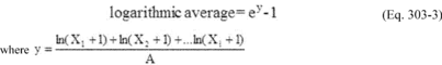
12.5 Percent Leaking Doors (PLD). Determine the total number of doors for which observations were made on the coke oven battery as follows:
12.5.1 For each test run (one run includes both the coke side and the push side traverses), sum the number of doors with door area VE. For batteries subject to an approved alternative standard under § 63.305 of this part, calculate the push side and the coke side PLD separately.
12.5.2 Calculate percent leaking doors by using Equation 303-5:
12.5.3 When traverses are conducted from the bench under sheds, calculate the coke side and the push side separately. Use Equation 303-6 to calculate a yard-equivalent reading:
If Lb is less than zero, use zero for Lb in Equation 303-7 in the calculation of PLD.12.5.3.1 Use Equation 303-7 to calculate PLD:
Round off PLD to the nearest hundredth of 1 percent and record as the percent leaking coke oven doors for the run.12.5.3.2 Average Percent Leaking Doors. Use Equation 303-8 to calculate the daily 30-day rolling average percent leaking doors for each battery using these current day's observations and the 29 previous valid daily sets of observations.
12.6 Topside Port Lids. Determine the percent leaking topside port lids for each run as follows:
12.6.1 Round off this percentage to the nearest hundredth of 1 percent and record this percentage as the percent leaking topside port lids for the run.
12.6.2 Average Percent Leaking Topside Port Lids. Use Equation 303-10 to calculate the daily 30-day rolling average percent leaking topside port lids for each battery using these current day's observations and the 29 previous valid daily sets of observations.
12.7 Offtake Systems. Determine the percent leaking offtake systems for the run as follows:
12.7.1 Round off this percentage to the nearest hundredth of 1 percent and record this percentage as the percent leaking offtake systems for the run.
12.7.2 Average Percent Leaking Offtake Systems. Use Equation 303-12 to calculate the daily 30-day rolling average percent leaking offtake systems for each battery using these current day's observations and the 29 previous valid daily sets of observations.
13.0 Method Performance [Reserved] 14.0 Pollution Prevention [Reserved] 15.0 Waste Management [Reserved] 16.0 References.1. Missan, R., and A. Stein. Guidelines for Evaluation of Visible Emissions Certification, Field Procedures, Legal Aspects, and Background Material. U.S. Environmental Protection Agency. EPA Publication No. EPA-340/1-75-007. April 1975.
2. Wohlschlegel, P., and D. E. Wagoner. Guideline for Development of a Quality Assurance Program: Volume IX - Visual Determination of Opacity Emission from Stationary Sources. U.S. Environmental Protection Agency. EPA Publication No. EPA-650/4-74-005i. November 1975.
3. U.S. Occupational Safety and Health Administration. Code of Federal Regulations. Title 29, Chapter XVII, Section 1910.1029(g). Washington, D.C. Government Printing Office. July 1, 1990.
4. U.S. Environmental Protection Agency. National Emission Standards for Hazardous Air Pollutants; Coke Oven Emissions from Wet-Coal Charged By-Product Coke Oven Batteries; Proposed Rule and Notice of Public Hearing. Washington, D.C. Federal Register. Vol. 52, No. 78 (13586). April 23, 1987.
17.0 Tables, Diagrams, Flowcharts, and Validation Data Company name: Battery no.: ___ Date: ___ Run no.: ___ City, State: Observer name: Company representative(s):| Charge No. | Oven No. |
Clock time | Visible emissions, seconds |
Comments |
|---|---|---|---|---|
| Time traverse started/completed | PS/CS | Door No. | Comments (No. of blocked doors, interruptions to traverse, etc.) |
|---|---|---|---|
| Time traverse started/completed | Type of Inspection (lids, offtakes, collecting main) |
Location of VE (Oven #/Port #) |
Comments |
|---|---|---|---|
This method does not include all of the specifications pertaining to observer certification. Some material is incorporated by reference from other methods in this part and in appendix A to 40 CFR Part 60. Therefore, to obtain reliable results, persons using this method should have a thorough knowledge of Method 9 and Method 303.
1.0 Scope and Application1.1 Applicability. This method is applicable for the determination of visible emissions (VE) from leaking doors at nonrecovery coke oven batteries.
2.0 Summary of Method2.1 A certified observer visually determines the VE from coke oven battery sources while walking at a normal pace. This method does not require that opacity of emissions be determined or that magnitude be differentiated.
3.0 Definitions3.1 Bench means the platform structure in front of the oven doors.
3.2 Coke oven door means each end enclosure on the push side and the coking side of an oven.
3.3 Coke side means the side of a battery from which the coke is discharged from ovens at the end of the coking cycle.
3.4 Nonrecovery coke oven battery means a source consisting of a group of ovens connected by common walls and operated as a unit, where coal undergoes destructive distillation under negative pressure to produce coke, and which is designed for the combustion of coke oven gas from which by-products are not recovered.
3.5 Operating oven means any oven not out of operation for rebuild or maintenance work extensive enough to require the oven to be skipped in the charging sequence.
3.6 Oven means a chamber in the coke oven battery in which coal undergoes destructive distillation to produce coke.
3.7 Push side means the side of the battery from which the coke is pushed from ovens at the end of the coking cycle.
3.8 Run means the observation of visible emissions from coke oven doors in accordance with this method.
3.9 Shed means an enclosure that covers the side of the coke oven battery, captures emissions from pushing operations and from leaking coke oven doors on the coke side or push side of the coke oven battery, and routes the emissions to a control device or system.
3.10 Traverse time means accumulated time for a traverse as measured by a stopwatch. Traverse time includes time to stop and write down oven numbers but excludes time waiting for obstructions of view to clear or for time to walk around obstacles.
3.11 Visible Emissions or VE means any emission seen by the unaided (except for corrective lenses) eye, excluding steam or condensing water.
4.0 Interferences [Reserved] 5.0 Safety5.1 Disclaimer. This method may involve hazardous materials, operations, and equipment. This test method may not address all of the safety problems associated with its use. It is the responsibility of the user of this test method to establish appropriate safety and health practices and determine the applicability of regulatory limitations prior to performing this test method.
5.2 Safety Training. Because coke oven batteries have hazardous environments, the training materials and the field training (Section 10.0) shall cover the precautions required by the company to address health and safety hazards. Special emphasis shall be given to the Occupational Safety and Health Administration (OSHA) regulations pertaining to exposure of coke oven workers (see Reference 3 in Section 16.0). In general, the regulation requires that special fire-retardant clothing and respirators be worn in certain restricted areas of the coke oven battery. The OSHA regulation also prohibits certain activities, such as chewing gum, smoking, and eating in these areas.
6.0 Equipment and Supplies [Reserved] 7.0 Reagents and Standards [Reserved] 8.0 Sample Collection, Preservation, Transport, and Storage [Reserved] 9.0 Quality Control [Reserved] 10.0 Calibration and Standardization.10.1 Training. This method requires only the determination of whether VE occur and does not require the determination of opacity levels; therefore, observer certification according to Method 9 in Appendix A to Part 60 is not required. However, the first-time observer (trainee) shall have attended the lecture portion of the Method 9 certification course. Furthermore, before conducting any VE observations, an observer shall become familiar with nonrecovery coke oven battery operations and with this test method by observing for a minimum of 4 hours the operation of a nonrecovery coke oven battery in the presence of personnel experienced in performing Method 303 assessments.
11.0 ProcedureThe intent of this procedure is to determine VE from coke oven door areas by carefully observing the door area while walking at a normal pace.
11.1 Number of Runs. Refer to § 63.309(c)(1) of this part for the appropriate number of runs.
11.2 Battery Traverse. To conduct a battery traverse, walk the length of the battery on the outside of the pusher machine and quench car tracks at a steady, normal walking pace, pausing to make appropriate entries on the door area inspection sheet (Figure 303A-1). The walking pace shall be such that the duration of the traverse does not exceed an average of 4 seconds per oven door, excluding time spent moving around stationary obstructions or waiting for other obstructions to move from positions blocking the view of a series of doors. Extra time is allowed for each leak (a maximum of 10 additional seconds for each leaking door) for the observer to make the proper notation. A walking pace of 3 seconds per oven door has been found to be typical. Record the actual traverse time with a stopwatch. A single test run consists of two timed traverses, one for the coke side and one for the push side.
11.2.1 Various situations may arise that will prevent the observer from viewing a door or a series of doors. The observer has two options for dealing with obstructions to view: (a) Wait for the equipment to move or the fugitive emissions to dissipate before completing the traverse; or (b) skip the affected ovens and move to an unobstructed position to continue the traverse. Continue the traverse. After the completion of the traverse, if the equipment has moved or the fugitive emissions have dissipated, complete the traverse by inspecting the affected doors. Record the oven numbers and make an appropriate notation under “Comments” on the door area inspection sheet (Figure 303A-1).
Note:Extra time incurred for handling obstructions is not counted in the traverse time.
11.2.2 When batteries have sheds to control pushing emissions, conduct the inspection from outside the shed, if the shed allows such observations, or from the bench. Be aware of special safety considerations pertinent to walking on the bench and follow the instructions of company personnel on the required equipment and operations procedures. If possible, conduct the bench traverse whenever the bench is clear of the door machine and hot coke guide.
11.3 Observations. Record all the information requested at the top of the door area inspection sheet (Figure 303A-1), including the number of non-operating ovens. Record which side is being inspected, i.e., coke side or push side. Other information may be recorded at the discretion of the observer, such as the location of the leak (e.g., top of the door), the reason for any interruption of the traverse, or the position of the sun relative to the battery and sky conditions (e.g., overcast, partly sunny, etc.).
11.3.1 Begin the test run by traversing either the coke side or the push side of the battery. After completing one side, traverse the other side.
11.3.2 During the traverse, look around the entire perimeter of each oven door. The door is considered leaking if VE are detected in the coke oven door area. The coke oven door area includes the entire area on the vertical face of a coke oven between the bench and the top of the battery and the adjacent doors on both sides. Record the oven number and make the appropriate notation on the door area inspection sheet (Figure 303A-1).
11.3.3 Do not record the following sources as door area VE:
11.3.3.1 VE from ovens with doors removed. Record the oven number and make an appropriate notation under “Comments”;
11.3.3.2 VE from ovens where maintenance work is being conducted. Record the oven number and make an appropriate notation under “Comments”; or
11.3.3.3 VE from hot coke that has been spilled on the bench as a result of pushing.
12.0 Data Analysis and CalculationsSame as Method 303, Section 12.1, 12.2, 12.3, 12.4, and 12.5.
13.0 Method Performance [Reserved] 14.0 Pollution Prevention [Reserved] 15.0 Waste Management [Reserved] 16.0 ReferencesSame as Method 303, Section 16.0.
17.0 Tables, Diagrams, Flowcharts, and Validation Data Company name: Battery no.: Date: City, State: Total no. of ovens in battery: Observer name: Certification expiration date: Inoperable ovens: Company representative(s): Traverse time CS: Traverse time PS: Valid run (Y or N):| Time traverse started/completed | PS/CS | Door No. | Comments (No. of blocked doors, interruptions to traverse, etc.) |
|---|---|---|---|
1.1 Applicability. This method is applicable for the determination of biodegradation rates of organic compounds in an activated sludge process. The test method is designed to evaluate the ability of an aerobic biological reaction system to degrade or destroy specific components in waste streams. The method may also be used to determine the effects of changes in wastewater composition on operation. The biodegradation rates determined by utilizing this method are not representative of a full-scale system. The rates measured by this method shall be used in conjunction with the procedures listed in appendix C of this part to calculate the fraction emitted to the air versus the fraction biodegraded.
2.0 Summary of Method2.1 A self-contained benchtop bioreactor system is assembled in the laboratory. A sample of mixed liquor is added and the waste stream is then fed continuously. The benchtop bioreactor is operated under conditions nearly identical to the target full-scale activated sludge process. Bioreactor temperature, dissolved oxygen concentration, average residence time in the reactor, waste composition, biomass concentration, and biomass composition of the full-scale process are the parameters which are duplicated in the benchtop bioreactor. Biomass shall be removed from the target full-scale activated sludge unit and held for no more than 4 hours prior to use in the benchtop bioreactor. If antifoaming agents are used in the full-scale system, they shall also be used in the benchtop bioreactor. The feed flowing into and the effluent exiting the benchtop bioreactor are analyzed to determine the biodegradation rates of the target compounds. The flow rate of the exit vent is used to calculate the concentration of target compounds (utilizing Henry's law) in the exit gas stream. If Henry's law constants for the compounds of interest are not known, this method cannot be used in the determination of the biodegradation rate and Method 304B is the suggested method. The choice of analytical methodology for measuring the compounds of interest at the inlet and outlet to the benchtop bioreactor are left to the discretion of the source, except where validated methods are available.
3.0 Definitions [Reserved] 4.0 Interferences [Reserved] 5.0 Safety5.1 If explosive gases are produced as a byproduct of biodegradation and could realistically pose a hazard, closely monitor headspace concentration of these gases to ensure laboratory safety. Placement of the benchtop bioreactor system inside a laboratory hood is recommended regardless of byproducts produced.
6.0. Equipment and Supplies Note:Figure 304A-1 illustrates a typical laboratory apparatus used to measure biodegradation rates. While the following description refers to Figure 304A-1, the EPA recognizes that alternative reactor configurations, such as alternative reactor shapes and locations of probes and the feed inlet, will also meet the intent of this method. Ensure that the benchtop bioreactor system is self-contained and isolated from the atmosphere (except for the exit vent stream) by leak-checking fittings, tubing, etc.
6.1 Benchtop Bioreactor. The biological reaction is conducted in a biological oxidation reactor of at least 6 liters capacity. The benchtop bioreactor is sealed and equipped with internal probes for controlling and monitoring dissolved oxygen and internal temperature. The top of the reactor is equipped for aerators, gas flow ports, and instrumentation (while ensuring that no leaks to the atmosphere exist around the fittings).
6.2 Aeration gas. Aeration gas is added to the benchtop bioreactor through three diffusers, which are glass tubes that extend to the bottom fifth of the reactor depth. A pure oxygen pressurized cylinder is recommended in order to maintain the specified oxygen concentration. Install a blower (e.g., Diaphragm Type, 15 SCFH capacity) to blow the aeration gas into the reactor diffusers. Measure the aeration gas flow rate with a rotameter (e.g., 0-15 SCFH recommended). The aeration gas will rise through the benchtop bioreactor, dissolving oxygen into the mixture in the process. The aeration gas must provide sufficient agitation to keep the solids in suspension. Provide an exit for the aeration gas from the top flange of the benchtop bioreactor through a water-cooled (e.g., Allihn-type) vertical condenser. Install the condenser through a gas-tight fitting in the benchtop bioreactor closure. Install a splitter which directs a portion of the gas to an exit vent and the rest of the gas through an air recycle pump back to the benchtop bioreactor. Monitor and record the flow rate through the exit vent at least 3 times per day throughout the day.
6.3 Wastewater Feed. Supply the wastewater feed to the benchtop bioreactor in a collapsible low-density polyethylene container or collapsible liner in a container (e.g., 20 L) equipped with a spigot cap (collapsible containers or liners of other material may be required due to the permeability of some volatile compounds through polyethylene). Obtain the wastewater feed by sampling the wastewater feed in the target process. A representative sample of wastewater shall be obtained from the piping leading to the aeration tank. This sample may be obtained from existing sampling valves at the discharge of the wastewater feed pump, or collected from a pipe discharging to the aeration tank, or by pumping from a well-mixed equalization tank upstream from the aeration tank. Alternatively, wastewater can be pumped continuously to the laboratory apparatus from a bleed stream taken from the equalization tank of the full-scale treatment system.
6.3.1 Refrigeration System. Keep the wastewater feed cool by ice or by refrigeration to 4 °C. If using a bleed stream from the equalization tank, refrigeration is not required if the residence time in the bleed stream is less than five minutes.
6.3.2 Wastewater Feed Pump. The wastewater is pumped from the refrigerated container using a variable-speed peristaltic pump drive equipped with a peristaltic pump head. Add the feed solution to the benchtop bioreactor through a fitting on the top flange. Determine the rate of feed addition to provide a retention time in the benchtop bioreactor that is numerically equivalent to the retention time in the full-scale system. The wastewater shall be fed at a rate sufficient to achieve 90 to 100 percent of the full-scale system residence time.
6.3.3 Treated wastewater feed. The benchtop bioreactor effluent exits at the bottom of the reactor through a tube and proceeds to the clarifier.
6.4 Clarifier. The effluent flows to a separate closed clarifier that allows separation of biomass and effluent (e.g., 2-liter pear-shaped glass separatory funnel, modified by removing the stopcock and adding a 25-mm OD glass tube at the bottom). Benchtop bioreactor effluent enters the clarifier through a tube inserted to a depth of 0.08 m (3 in.) through a stopper at the top of the clarifier. System effluent flows from a tube inserted through the stopper at the top of the clarifier to a drain (or sample bottle when sampling). The underflow from the clarifier leaves from the glass tube at the bottom of the clarifier. Flexible tubing connects this fitting to the sludge recycle pump. This pump is coupled to a variable speed pump drive. The discharge from this pump is returned through a tube inserted in a port on the side of the benchtop bioreactor. An additional port is provided near the bottom of the benchtop bioreactor for sampling the reactor contents. The mixed liquor from the benchtop bioreactor flows into the center of the clarifier. The clarified system effluent separates from the biomass and flows through an exit near the top of the clarifier. There shall be no headspace in the clarifier.
6.5 Temperature Control Apparatus. Capable of maintaining the system at a temperature equal to the temperature of the full-scale system. The average temperature should be maintained within ±2 °C of the set point.
6.5.1 Temperature Monitoring Device. A resistance type temperature probe or a thermocouple connected to a temperature readout with a resolution of 0.1 °C or better.
6.5.2 Benchtop Bioreactor Heater. The heater is connected to the temperature control device.
6.6 Oxygen Control System. Maintain the dissolved oxygen concentration at the levels present in the full-scale system. Target full-scale activated sludge systems with dissolved oxygen concentration below 2 mg/L are required to maintain the dissolved oxygen concentration in the benchtop ioreactor within 0.5 mg/L of the target dissolved oxygen level. Target full-scale activated sludge systems with dissolved oxygen concentration above 2 mg/L are required to maintain the dissolved oxygen concentration in the benchtop bioreactor within 1.5 mg/L of the target dissolved oxygen concentration; however, for target full-scale activated sludge systems with dissolved oxygen concentrations above 2 mg/L, the dissolved oxygen concentration in the benchtop bioreactor may not drop below 1.5 mg/L. If the benchtop bioreactor is outside the control range, the dissolved oxygen is noted and the reactor operation is adjusted.
6.6.1 Dissolved Oxygen Monitor. Dissolved oxygen is monitored with a polarographic probe (gas permeable membrane) connected to a dissolved oxygen meter (e.g., 0 to 15 mg/L, 0 to 50 °C).
6.6.2 Benchtop Bioreactor Pressure Monitor. The benchtop bioreactor pressure is monitored through a port in the top flange of the reactor. This is connected to a gauge control with a span of 13-cm water vacuum to 13-cm water pressure or better. A relay is activated when the vacuum exceeds an adjustable setpoint which opens a solenoid valve (normally closed), admitting oxygen to the system. The vacuum setpoint controlling oxygen addition to the system shall be set at approximately 2.5 ±0.5 cm water and maintained at this setting except during brief periods when the dissolved oxygen concentration is adjusted.
6.7 Connecting Tubing. All connecting tubing shall be Teflon or equivalent in impermeability. The only exception to this specification is the tubing directly inside the pump head of the wastewater feed pump, which may be Viton, Silicone or another type of flexible tubing.
Note:Mention of trade names or products does not constitute endorsement by the U.S. Environmental Protection Agency.
7.0 Reagents and Standards7.1 Wastewater. Obtain a representative sample of wastewater at the inlet to the full-scale treatment plant if there is an existing full-scale treatment plant (see section 6.3). If there is no existing full-scale treatment plant, obtain the wastewater sample as close to the point of determination as possible. Collect the sample by pumping the wastewater into the 20-L collapsible container. The loss of volatiles shall be minimized from the wastewater by collapsing the container before filling, by minimizing the time of filling, and by avoiding a headspace in the container after filling. If the wastewater requires the addition of nutrients to support the biomass growth and maintain biomass characteristics, those nutrients are added and mixed with the container contents after the container is filled.
7.2 Biomass. Obtain the biomass or activated sludge used for rate constant determination in the bench-scale process from the existing full-scale process or from a representative biomass culture (e.g., biomass that has been developed for a future full-scale process). This biomass is preferentially obtained from a thickened acclimated mixed liquor sample. Collect the sample either by bailing from the mixed liquor in the aeration tank with a weighted container, or by collecting aeration tank effluent at the effluent overflow weir. Transport the sample to the laboratory within no more than 4 hours of collection. Maintain the biomass concentration in the benchtop bioreactor at the level of the full-scale system + 10 percent throughout the sampling period of the test method.
8.0 Sample Collection, Preservation, Storage, and Transport8.1 Benchtop Bioreactor Operation. Charge the mixed liquor to the benchtop bioreactor, minimizing headspace over the liquid surface to minimize entrainment of mixed liquor in the circulating gas. Fasten the benchtop bioreactor headplate to the reactor over the liquid surface. Maintain the temperature of the contents of the benchtop bioreactor system at the temperature of the target full-scale system, ±2 °C, throughout the testing period. Monitor and record the temperature of the benchtop bioreactor contents at least to the nearest 0.1 °C.
8.1.1 Wastewater Storage. Collect the wastewater sample in the 20-L collapsible container. Store the container at 4 °C throughout the testing period. Connect the container to the benchtop bioreactor feed pump.
8.1.2 Wastewater Flow Rate.
8.1.2.1 The hydraulic residence time of the aeration tank is calculated as the ratio of the volume of the tank (L) to the flow rate (L/min). At the beginning of a test, the container shall be connected to the feed pump and solution shall be pumped to the benchtop bioreactor at the required flow rate to achieve the calculated hydraulic residence time of wastewater in the aeration tank.
Where: Qtest = wastewater flow rate (L/min) Qfs = average flow rate of full-scale process (L/min) Vfs = volume of full-scale aeration tank (L)8.1.2.2 The target flow rate in the test apparatus is the same as the flow rate in the target full-scale process multiplied by the ratio of benchtop bioreactor volume (e.g., 6 L) to the volume of the full-scale aeration tank. The hydraulic residence time shall be maintained at 90 to 100 percent of the residence time maintained in the full-scale unit. A nominal flow rate is set on the pump based on a pump calibration. Changes in the elasticity of the tubing in the pump head and the accumulation of material in the tubing affect this calibration. The nominal pumping rate shall be changed as necessary based on volumetric flow measurements. Discharge the benchtop bioreactor effluent to a wastewater storage, treatment, or disposal facility, except during sampling or flow measurement periods.
8.1.3 Sludge Recycle Rate. Set the sludge recycle rate at a rate sufficient to prevent accumulation in the bottom of the clarifier. Set the air circulation rate sufficient to maintain the biomass in suspension.
8.1.4 Benchtop Bioreactor Operation and Maintenance. Temperature, dissolved oxygen concentration, exit vent flow rate, benchtop bioreactor effluent flow rate, and air circulation rate shall be measured and recorded three times throughout each day of benchtop bioreactor operation. If other parameters (such as pH) are measured and maintained in the target full-scale unit, these parameters, where appropriate, shall be monitored and maintained to target full-scale specifications in the benchtop bioreactor. At the beginning of each sampling period (Section 8.2), sample the benchtop bioreactor contents for suspended solids analysis. Take this sample by loosening a clamp on a length of tubing attached to the lower side port. Determine the suspended solids gravimetrically by the Gooch crucible/glass fiber filter method for total suspended solids, in accordance with Standard Methods 3 or equivalent. When necessary, sludge shall be wasted from the lower side port of the benchtop bioreactor, and the volume that is wasted shall be replaced with an equal volume of the reactor effluent. Add thickened activated sludge mixed liquor as necessary to the benchtop bioreactor to increase the suspended solids concentration to the desired level. Pump this mixed liquor to the benchtop bioreactor through the upper side port (Item 24 in Figure 304A-1). Change the membrane on the dissolved oxygen probe before starting the test. Calibrate the oxygen probe immediately before the start of the test and each time the membrane is changed.
8.1.5 Inspection and Correction Procedures. If the feed line tubing becomes clogged, replace with new tubing. If the feed flow rate is not within 5 percent of target flow any time the flow rate is measured, reset pump or check the flow measuring device and measure flow rate again until target flow rate is achieved.
8.2 Test Sampling. At least two and one half hydraulic residence times after the system has reached the targeted specifications shall be permitted to elapse before the first sample is taken. Effluent samples of the clarifier discharge (Item 20 in Figure 304A-1) and the influent wastewater feed are collected in 40-mL septum vials to which two drops of 1:10 hydrochloric acid (HCl) in water have been added. Sample the clarifier discharge directly from the drain line. These samples will be composed of the entire flow from the system for a period of several minutes. Feed samples shall be taken from the feed pump suction line after temporarily stopping the benchtop bioreactor feed, removing a connector, and squeezing the collapsible feed container. Store both influent and effluent samples at 4 °C immediately after collection and analyze within 8 hours of collection.
8.2.1 Frequency of Sampling. During the test, sample and analyze the wastewater feed and the clarifier effluent at least six times. The sampling intervals shall be separated by at least 8 hours. During any individual sampling interval, sample the wastewater feed simultaneously with or immediately after the effluent sample. Calculate the relative standard deviation (RSD) of the amount removed (i.e., effluent concentration - wastewater feed concentration). The RSD values shall be <15 percent. If an RSD value is >15 percent, continue sampling and analyzing influent and effluent sets of samples until the RSD values are within specifications.
8.2.2 Sampling After Exposure of System to Atmosphere. If, after starting sampling procedures, the benchtop bioreactor system is exposed to the atmosphere (due to leaks, maintenance, etc.), allow at least one hydraulic residence time to elapse before resuming sampling.
9.0 Quality Control9.1 Dissolved Oxygen. Fluctuation in dissolved oxygen concentration may occur for numerous reasons, including undetected gas leaks, increases and decreases in mixed liquor suspended solids resulting from cell growth and solids loss in the effluent stream, changes in diffuser performance, cycling of effluent flow rate, and overcorrection due to faulty or sluggish dissolved oxygen probe response. Control the dissolved oxygen concentration in the benchtop bioreactor by changing the proportion of oxygen in the circulating aeration gas. Should the dissolved oxygen concentration drift below the designated experimental condition, bleed a small amount of aeration gas from the system on the pressure side (i.e., immediately upstream of one of the diffusers). This will create a vacuum in the system, triggering the pressure sensitive relay to open the solenoid valve and admit oxygen to the system. Should the dissolved oxygen concentration drift above the designated experimental condition, slow or stop the oxygen input to the system until the dissolved oxygen concentration approaches the correct level.
9.2 Sludge Wasting.
9.2.1 Determine the suspended solids concentration (section 8.1.4) at the beginning of a test, and once per day thereafter during the test. If the test is completed within a two day period, determine the suspended solids concentration after the final sample set is taken. If the suspended solids concentration exceeds the specified concentration, remove a fraction of the sludge from the benchtop bioreactor. The required volume of mixed liquor to remove is determined as follows:
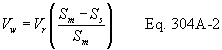 Where: Vw
is the wasted volume (Liters), Vr is the volume of the benchtop
bioreactor (Liters), Sm is the measured solids (g/L), and Ss is the
specified solids (g/L).
Where: Vw
is the wasted volume (Liters), Vr is the volume of the benchtop
bioreactor (Liters), Sm is the measured solids (g/L), and Ss is the
specified solids (g/L).
9.2.2 Remove the mixed liquor from the benchtop bioreactor by loosening a clamp on the mixed liquor sampling tube and allowing the required volume to drain to a graduated flask. Clamp the tube when the correct volume has been wasted. Replace the volume of the liquid wasted by pouring the same volume of effluent back into the benchtop bioreactor. Dispose of the waste sludge properly.
9.3 Sludge Makeup. In the event that the suspended solids concentration is lower than the specifications, add makeup sludge back into the benchtop bioreactor. Determine the amount of sludge added by the following equation:
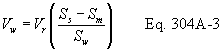 Where: Vw
is the volume of sludge to add (Liters), Vr is the volume of the
benchtop bioreactor (Liters), Sw is the solids in the makeup sludge
(g/L), Sm is the measured solids (g/L), and Ss is the specified
solids (g/L). 10.0 Calibration and Standardization
Where: Vw
is the volume of sludge to add (Liters), Vr is the volume of the
benchtop bioreactor (Liters), Sw is the solids in the makeup sludge
(g/L), Sm is the measured solids (g/L), and Ss is the specified
solids (g/L). 10.0 Calibration and Standardization
10.1 Wastewater Pump Calibration. Determine the wastewater flow rate by collecting the system effluent for a time period of at least one hour, and measuring the volume with a graduated cylinder. Record the collection time period and volume collected. Determine flow rate. Adjust the pump speed to deliver the specified flow rate.
10.2 Calibration Standards. Prepare calibration standards from pure certified standards in an aqueous medium. Prepare and analyze three concentrations of calibration standards for each target component (or for a mixture of components) in triplicate daily throughout the analyses of the test samples. At each concentration level, a single calibration shall be within 5 percent of the average of the three calibration results. The low and medium calibration standards shall bracket the expected concentration of the effluent (treated) wastewater. The medium and high standards shall bracket the expected influent concentration.
11.0 Analytical Procedures11.1 Analysis. If the identity of the compounds of interest in the wastewater is not known, a representative sample of the wastewater shall be analyzed in order to identify all of the compounds of interest present. A gas chromatography/mass spectrometry screening method is recommended.
11.1.1 After identifying the compounds of interest in the wastewater, develop and/or use one or more analytical techniques capable of measuring each of those compounds (more than one analytical technique may be required, depending on the characteristics of the wastewater). Test Method 18, found in appendix A of 40 CFR 60, may be used as a guideline in developing the analytical technique. Purge and trap techniques may be used for analysis providing the target components are sufficiently volatile to make this technique appropriate. The limit of quantitation for each compound shall be determined (see reference 1). If the effluent concentration of any target compound is below the limit of quantitation determined for that compound, the operation of the Method 304 unit may be altered to attempt to increase the effluent concentration above the limit of quantitation. Modifications to the method shall be approved prior to the test. The request should be addressed to Method 304 contact, Emissions Measurement Center, Mail Drop 19, U.S. Environmental Protection Agency, Research Triangle Park, NC 27711.
12.0 Data Analysis and Calculations12.1 Nomenclature. The following symbols are used in the calculations.
Ci = Average inlet feed concentration for a compound of interest, as analyzed (mg/L) Co = Average outlet (effluent) concentration for a compound of interest, as analyzed (mg/L) X = Biomass concentration, mixed liquor suspended solids (g/L) t = Hydraulic residence time in the benchtop bioreactor (hours) V = Volume of the benchtop bioreactor (L) Q = Flow rate of wastewater into the benchtop bioreactor, average (L/hour)12.2 Residence Time. The hydraulic residence time of the benchtop bioreactor is equal to the ratio of the volume of the benchtop bioreactor (L) to the flow rate (L/h):
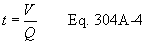
12.3 Rate of Biodegradation. Calculate the rate of biodegradation for each component with the following equation:
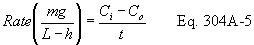
12.4 First-Order Biorate Constant. Calculate the first-order biorate constant (K1) for each component with the following equation:
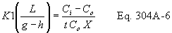
12.5 Relative Standard Deviation (RSD). Determine the standard deviation of both the influent and effluent sample concentrations (S) using the following equation:
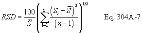
12.6 Determination of Percent Air Emissions and Percent Biodegraded. Use the results from this test method and follow the applicable procedures in appendix C of 40 CFR part 63, entitled, “Determination of the Fraction Biodegraded (Fbio) in a Biological Treatment Unit” to determine Fbio.
13.0 Method Performance [Reserved] 14.0 Pollution Prevention [Reserved] 15.0 Waste Management [Reserved] 16.0 References1. “Guidelines for data acquisition and data quality evaluation in Environmental Chemistry,” Daniel MacDoughal, Analytical Chemistry, Volume 52, p. 2242, 1980.
2. Test Method 18, 40 CFR 60, appendix A.
3. Standard Methods for the Examination of Water and Wastewater, 16th Edition, Method 209C, Total Suspended Solids Dried at 103-105 °C, APHA, 1985.
4. Water7, Hazardous Waste Treatment, Storage, and Disposal Facilities (TSDF) - Air Emission Models, U.S. Environmental Protection Agency, EPA-450/3-87-026, Review Draft, November 1989.
5. Chemdat7, Hazardous Waste Treatment, Storage, and Disposal Facilities (TSDF) - Air Emission Models, U.S. Environmental Protection Agency, EPA-450/3-87-026, Review Draft, November 1989.
17.0 Tables, Diagrams, Flowcharts, and Validation Data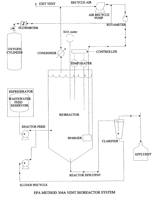 Method 304B:
Determination of Biodegradation Rates of Organic Compounds
(Scrubber Option) 1.0 Scope and Application
Method 304B:
Determination of Biodegradation Rates of Organic Compounds
(Scrubber Option) 1.0 Scope and Application
1.1 Applicability. This method is applicable for the determination of biodegradation rates of organic compounds in an activated sludge process. The test method is designed to evaluate the ability of an aerobic biological reaction system to degrade or destroy specific components in waste streams. The method may also be used to determine the effects of changes in wastewater composition on operation. The biodegradation rates determined by utilizing this method are not representative of a full-scale system. Full-scale systems embody biodegradation and air emissions in competing reactions. This method measures biodegradation in absence of air emissions. The rates measured by this method shall be used in conjunction with the procedures listed in appendix C of this part to calculate the fraction emitted to the air versus the fraction biodegraded.
2.0 Summary of Method2.1 A self-contained benchtop bioreactor system is assembled in the laboratory. A sample of mixed liquor is added and the waste stream is then fed continuously. The benchtop bioreactor is operated under conditions nearly identical to the target full-scale activated sludge process, except that air emissions are not a factor. The benchtop bioreactor temperature, dissolved oxygen concentration, average residence time in the reactor, waste composition, biomass concentration, and biomass composition of the target full-scale process are the parameters which are duplicated in the laboratory system. Biomass shall be removed from the target full-scale activated sludge unit and held for no more than 4 hours prior to use in the benchtop bioreactor. If antifoaming agents are used in the full-scale system, they shall also be used in the benchtop bioreactor. The feed flowing into and the effluent exiting the benchtop bioreactor are analyzed to determine the biodegradation rates of the target compounds. The choice of analytical methodology for measuring the compounds of interest at the inlet and outlet to the benchtop bioreactor are left to the discretion of the source, except where validated methods are available.
3.0 Definitions [Reserved] 4.0 Interferences [Reserved] 5.0 Safety5.1 If explosive gases are produced as a byproduct of biodegradation and could realistically pose a hazard, closely monitor headspace concentration of these gases to ensure laboratory safety. Placement of the benchtop bioreactor system inside a laboratory hood is recommended regardless of byproducts produced.
6.0 Equipment and Supplies Note:Figure 304B-1 illustrates a typical laboratory apparatus used to measure biodegradation rates. While the following description refers to Figure 304B-1, the EPA recognizes that alternative reactor configurations, such as alternative reactor shapes and locations of probes and the feed inlet, will also meet the intent of this method. Ensure that the benchtop bioreactor system is self-contained and isolated from the atmosphere by leak-checking fittings, tubing, etc.
6.1 Benchtop Bioreactor. The biological reaction is conducted in a biological oxidation reactor of at least 6-liters capacity. The benchtop bioreactor is sealed and equipped with internal probes for controlling and monitoring dissolved oxygen and internal temperature. The top of the benchtop bioreactor is equipped for aerators, gas flow ports, and instrumentation (while ensuring that no leaks to the atmosphere exist around the fittings).
6.2 Aeration gas. Aeration gas is added to the benchtop bioreactor through three diffusers, which are glass tubes that extend to the bottom fifth of the reactor depth. A pure oxygen pressurized cylinder is recommended in order to maintain the specified oxygen concentration. Install a blower (e.g., Diaphragm Type, 15 SCFH capacity) to blow the aeration gas into the benchtop bioreactor diffusers. Measure the aeration gas flow rate with a rotameter (e.g., 0-15 SCFH recommended). The aeration gas will rise through the benchtop bioreactor, dissolving oxygen into the mixture in the process. The aeration gas must provide sufficient agitation to keep the solids in suspension. Provide an exit for the aeration gas from the top flange of the benchtop bioreactor through a water-cooled (e.g., Allihn-type) vertical condenser. Install the condenser through a gas-tight fitting in the benchtop bioreactor closure. Design the system so that at least 10 percent of the gas flows through an alkaline scrubber containing 175 mL of 45 percent by weight solution of potassium hydroxide (KOH) and 5 drops of 0.2 percent alizarin yellow dye. Route the balance of the gas through an adjustable scrubber bypass. Route all of the gas through a 1-L knock-out flask to remove entrained moisture and then to the intake of the blower. The blower recirculates the gas to the benchtop bioreactor.
6.3 Wastewater Feed. Supply the wastewater feed to the benchtop bioreactor in a collapsible low-density polyethylene container or collapsible liner in a container (e.g., 20 L) equipped with a spigot cap (collapsible containers or liners of other material may be required due to the permeability of some volatile compounds through polyethylene). Obtain the wastewater feed by sampling the wastewater feed in the target process. A representative sample of wastewater shall be obtained from the piping leading to the aeration tank. This sample may be obtained from existing sampling valves at the discharge of the wastewater feed pump, or collected from a pipe discharging to the aeration tank, or by pumping from a well-mixed equalization tank upstream from the aeration tank. Alternatively, wastewater can be pumped continuously to the laboratory apparatus from a bleed stream taken from the equalization tank of the full-scale treatment system.
6.3.1 Refrigeration System. Keep the wastewater feed cool by ice or by refrigeration to 4 °C. If using a bleed stream from the equalization tank, refrigeration is not required if the residence time in the bleed stream is less than five minutes.
6.3.2 Wastewater Feed Pump. The wastewater is pumped from the refrigerated container using a variable-speed peristaltic pump drive equipped with a peristaltic pump head. Add the feed solution to the benchtop bioreactor through a fitting on the top flange. Determine the rate of feed addition to provide a retention time in the benchtop bioreactor that is numerically equivalent to the retention time in the target full-scale system. The wastewater shall be fed at a rate sufficient to achieve 90 to 100 percent of the target full-scale system residence time.
6.3.3 Treated wastewater feed. The benchtop bioreactor effluent exits at the bottom of the reactor through a tube and proceeds to the clarifier.
6.4 Clarifier. The effluent flows to a separate closed clarifier that allows separation of biomass and effluent (e.g., 2-liter pear-shaped glass separatory funnel, modified by removing the stopcock and adding a 25-mm OD glass tube at the bottom). Benchtop bioreactor effluent enters the clarifier through a tube inserted to a depth of 0.08 m (3 in.) through a stopper at the top of the clarifier. System effluent flows from a tube inserted through the stopper at the top of the clarifier to a drain (or sample bottle when sampling). The underflow from the clarifier leaves from the glass tube at the bottom of the clarifier. Flexible tubing connects this fitting to the sludge recycle pump. This pump is coupled to a variable speed pump drive. The discharge from this pump is returned through a tube inserted in a port on the side of the benchtop bioreactor. An additional port is provided near the bottom of the benchtop bioreactor for sampling the reactor contents. The mixed liquor from the benchtop bioreactor flows into the center of the clarifier. The clarified system effluent separates from the biomass and flows through an exit near the top of the clarifier. There shall be no headspace in the clarifier.
6.5 Temperature Control Apparatus. Capable of maintaining the system at a temperature equal to the temperature of the full-scale system. The average temperature should be maintained within ±2 °C of the set point.
6.5.1 Temperature Monitoring Device. A resistance type temperature probe or a thermocouple connected to a temperature readout with a resolution of 0.1 °C or better.
6.5.2 Benchtop Bioreactor Heater. The heater is connected to the temperature control device.
6.6 Oxygen Control System. Maintain the dissolved oxygen concentration at the levels present in the full-scale system. Target full-scale activated sludge systems with dissolved oxygen concentration below 2 mg/L are required to maintain the dissolved oxygen concentration in the benchtop bioreactor within 0.5 mg/L of the target dissolved oxygen level. Target full-scale activated sludge systems with dissolved oxygen concentration above 2 mg/L are required to maintain the dissolved oxygen concentration in the benchtop bioreactor within 1.5 mg/L of the target dissolved oxygen concentration; however, for target full-scale activated sludge systems with dissolved oxygen concentrations above 2 mg/L, the dissolved oxygen concentration in the benchtop bioreactor may not drop below 1.5 mg/L. If the benchtop bioreactor is outside the control range, the dissolved oxygen is noted and the reactor operation is adjusted.
6.6.1 Dissolved Oxygen Monitor. Dissolved oxygen is monitored with a polarographic probe (gas permeable membrane) connected to a dissolved oxygen meter (e.g., 0 to 15 mg/L, 0 to 50 °C).
6.6.2 Benchtop Bioreactor Pressure Monitor. The benchtop bioreactor pressure is monitored through a port in the top flange of the reactor. This is connected to a gauge control with a span of 13-cm water vacuum to 13-cm water pressure or better. A relay is activated when the vacuum exceeds an adjustable setpoint which opens a solenoid valve (normally closed), admitting oxygen to the system. The vacuum setpoint controlling oxygen addition to the system shall be set at approximately 2.5 ±0.5 cm water and maintained at this setting except during brief periods when the dissolved oxygen concentration is adjusted.
6.7 Connecting Tubing. All connecting tubing shall be Teflon or equivalent in impermeability. The only exception to this specification is the tubing directly inside the pump head of the wastewater feed pump, which may be Viton, Silicone or another type of flexible tubing.
Note:Mention of trade names or products does not constitute endorsement by the U.S. Environmental Protection Agency.
7.0. Reagents and Standards7.1 Wastewater. Obtain a representative sample of wastewater at the inlet to the full-scale treatment plant if there is an existing full-scale treatment plant (See Section 6.3). If there is no existing full-scale treatment plant, obtain the wastewater sample as close to the point of determination as possible. Collect the sample by pumping the wastewater into the 20-L collapsible container. The loss of volatiles shall be minimized from the wastewater by collapsing the container before filling, by minimizing the time of filling, and by avoiding a headspace in the container after filling. If the wastewater requires the addition of nutrients to support the biomass growth and maintain biomass characteristics, those nutrients are added and mixed with the container contents after the container is filled.
7.2 Biomass. Obtain the biomass or activated sludge used for rate constant determination in the bench-scale process from the existing full-scale process or from a representative biomass culture (e.g., biomass that has been developed for a future full-scale process). This biomass is preferentially obtained from a thickened acclimated mixed liquor sample. Collect the sample either by bailing from the mixed liquor in the aeration tank with a weighted container, or by collecting aeration tank effluent at the effluent overflow weir. Transport the sample to the laboratory within no more than 4 hours of collection. Maintain the biomass concentration in the benchtop bioreactor at the level of the target full-scale system + 10 percent throughout the sampling period of the test method.
8.0 Sample Collection, Preservation, Storage, and Transport8.1 Benchtop Bioreactor Operation. Charge the mixed liquor to the benchtop bioreactor, minimizing headspace over the liquid surface to minimize entrainment of mixed liquor in the circulating gas. Fasten the benchtop bioreactor headplate to the reactor over the liquid surface. Maintain the temperature of the contents of the benchtop bioreactor system at the temperature of the target full-scale system, ±2 °C, throughout the testing period. Monitor and record the temperature of the reactor contents at least to the nearest 0.1 °C.
8.1.1 Wastewater Storage. Collect the wastewater sample in the 20-L collapsible container. Store the container at 4 °C throughout the testing period. Connect the container to the benchtop bioreactor feed pump.
8.1.2 Wastewater Flow Rate.
8.1.2.1 The hydraulic residence time of the aeration tank is calculated as the ratio of the volume of the tank (L) to the flow rate (L/min). At the beginning of a test, the container shall be connected to the feed pump and solution shall be pumped to the benchtop bioreactor at the required flow rate to achieve the calculated hydraulic residence time of wastewater in the aeration tank.
Where: Qtest = wastewater flow rate (L/min) Qfs = average flow rate of full-scale process (L/min) Vfs = volume of full-scale aeration tank (L)8.1.2.2 The target flow rate in the test apparatus is the same as the flow rate in the target full-scale process multiplied by the ratio of benchtop bioreactor volume (e.g., 6 L) to the volume of the full-scale aeration tank. The hydraulic residence time shall be maintained at 90 to 100 percent of the residence time maintained in the target full-scale unit. A nominal flow rate is set on the pump based on a pump calibration. Changes in the elasticity of the tubing in the pump head and the accumulation of material in the tubing affect this calibration. The nominal pumping rate shall be changed as necessary based on volumetric flow measurements. Discharge the benchtop bioreactor effluent to a wastewater storage, treatment, or disposal facility, except during sampling or flow measurement periods.
8.1.3 Sludge Recycle Rate. Set the sludge recycle rate at a rate sufficient to prevent accumulation in the bottom of the clarifier. Set the air circulation rate sufficient to maintain the biomass in suspension.
8.1.4 Benchtop Bioreactor Operation and Maintenance. Temperature, dissolved oxygen concentration, flow rate, and air circulation rate shall be measured and recorded three times throughout each day of testing. If other parameters (such as pH) are measured and maintained in the target full-scale unit, these parameters shall, where appropriate, be monitored and maintained to full-scale specifications in the benchtop bioreactor. At the beginning of each sampling period (section 8.2), sample the benchtop bioreactor contents for suspended solids analysis. Take this sample by loosening a clamp on a length of tubing attached to the lower side port. Determine the suspended solids gravimetrically by the Gooch crucible/glass fiber filter method for total suspended solids, in accordance with Standard Methods 3 or equivalent. When necessary, sludge shall be wasted from the lower side port of the benchtop bioreactor, and the volume that is wasted shall be replaced with an equal volume of the benchtop bioreactor effluent. Add thickened activated sludge mixed liquor as necessary to the benchtop bioreactor to increase the suspended solids concentration to the desired level. Pump this mixed liquor to the benchtop bioreactor through the upper side port (Item 24 in Figure 304B-1). Change the membrane on the dissolved oxygen probe before starting the test. Calibrate the oxygen probe immediately before the start of the test and each time the membrane is changed. The scrubber solution shall be replaced each weekday with 175 mL 45 percent W/W KOH solution to which five drops of 0.2 percent alizarin yellow indicator in water have been added. The potassium hydroxide solution in the alkaline scrubber shall be changed if the alizarin yellow dye color changes.
8.1.5 Inspection and Correction Procedures. If the feed line tubing becomes clogged, replace with new tubing. If the feed flow rate is not within 5 percent of target flow any time the flow rate is measured, reset pump or check the flow measuring device and measure flow rate again until target flow rate is achieved.
8.2 Test Sampling. At least two and one half hydraulic residence times after the system has reached the targeted specifications shall be permitted to elapse before the first sample is taken. Effluent samples of the clarifier discharge (Item 20 in Figure 304B-1) and the influent wastewater feed are collected in 40-mL septum vials to which two drops of 1:10 hydrochloric acid (HCl) in water have been added. Sample the clarifier discharge directly from the drain line. These samples will be composed of the entire flow from the system for a period of several minutes. Feed samples shall be taken from the feed pump suction line after temporarily stopping the benchtop bioreactor feed, removing a connector, and squeezing the collapsible feed container. Store both influent and effluent samples at 4 °C immediately after collection and analyze within 8 hours of collection.
8.2.1 Frequency of Sampling. During the test, sample and analyze the wastewater feed and the clarifier effluent at least six times. The sampling intervals shall be separated by at least 8 hours. During any individual sampling interval, sample the wastewater feed simultaneously with or immediately after the effluent sample. Calculate the RSD of the amount removed (i.e., effluent concentration - wastewater feed concentration). The RSD values shall be <15 percent. If an RSD value is >15 percent, continue sampling and analyzing influent and effluent sets of samples until the RSD values are within specifications.
8.2.2 Sampling After Exposure of System to Atmosphere. If, after starting sampling procedures, the benchtop bioreactor system is exposed to the atmosphere (due to leaks, maintenance, etc.), allow at least one hydraulic residence time to elapse before resuming sampling.
9.0 Quality Control9.1 Dissolved Oxygen. Fluctuation in dissolved oxygen concentration may occur for numerous reasons, including undetected gas leaks, increases and decreases in mixed liquor suspended solids resulting from cell growth and solids loss in the effluent stream, changes in diffuser performance, cycling of effluent flow rate, and overcorrection due to faulty or sluggish dissolved oxygen probe response. Control the dissolved oxygen concentration in the benchtop bioreactor by changing the proportion of oxygen in the circulating aeration gas. Should the dissolved oxygen concentration drift below the designated experimental condition, bleed a small amount of aeration gas from the system on the pressure side (i.e., immediately upstream of one of the diffusers). This will create a vacuum in the system, triggering the pressure sensitive relay to open the solenoid valve and admit oxygen to the system. Should the dissolved oxygen concentration drift above the designated experimental condition, slow or stop the oxygen input to the system until the dissolved oxygen concentration approaches the correct level.
9.2 Sludge Wasting.
9.2.1 Determine the suspended solids concentration (section 8.1.4) at the beginning of a test, and once per day thereafter during the test. If the test is completed within a two day period, determine the suspended solids concentration after the final sample set is taken. If the suspended solids concentration exceeds the specified concentration, remove a fraction of the sludge from the benchtop bioreactor. The required volume of mixed liquor to remove is determined as follows:
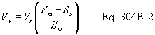 Where: Vw
is the wasted volume (Liters), Vr is the volume of the benchtop
bioreactor (Liters), Sm is the measured solids (g/L), and Ss is the
specified solids (g/L).
Where: Vw
is the wasted volume (Liters), Vr is the volume of the benchtop
bioreactor (Liters), Sm is the measured solids (g/L), and Ss is the
specified solids (g/L).
9.2.2 Remove the mixed liquor from the benchtop bioreactor by loosening a clamp on the mixed liquor sampling tube and allowing the required volume to drain to a graduated flask. Clamp the tube when the correct volume has been wasted. Replace the volume of the liquid wasted by pouring the same volume of effluent back into the benchtop bioreactor. Dispose of the waste sludge properly.
9.3 Sludge Makeup. In the event that the suspended solids concentration is lower than the specifications, add makeup sludge back into the benchtop bioreactor. Determine the amount of sludge added by the following equation:
Where: Vw is the volume of sludge to add (Liters), Vr is the volume of the benchtop bioreactor (Liters), Sw is the solids in the makeup sludge (g/L), Sm is the measured solids (g/L), and Ss is the specified solids (g/L). 10.0 Calibration and Standardizations10.1 Wastewater Pump Calibration. Determine the wastewater flow rate by collecting the system effluent for a time period of at least one hour, and measuring the volume with a graduated cylinder. Record the collection time period and volume collected. Determine flow rate. Adjust the pump speed to deliver the specified flow rate.
10.2 Calibration Standards. Prepare calibration standards from pure certified standards in an aqueous medium. Prepare and analyze three concentrations of calibration standards for each target component (or for a mixture of components) in triplicate daily throughout the analyses of the test samples. At each concentration level, a single calibration shall be within 5 percent of the average of the three calibration results. The low and medium calibration standards shall bracket the expected concentration of the effluent (treated) wastewater. The medium and high standards shall bracket the expected influent concentration.
11.0 Analytical Test Procedures11.1 Analysis. If the identity of the compounds of interest in the wastewater is not known, a representative sample of the wastewater shall be analyzed in order to identify all of the compounds of interest present. A gas chromatography/mass spectrometry screening method is recommended.
11.1.1 After identifying the compounds of interest in the wastewater, develop and/or use one or more analytical technique capable of measuring each of those compounds (more than one analytical technique may be required, depending on the characteristics of the wastewater). Method 18, found in appendix A of 40 CFR 60, may be used as a guideline in developing the analytical technique. Purge and trap techniques may be used for analysis providing the target components are sufficiently volatile to make this technique appropriate. The limit of quantitation for each compound shall be determined. 1 If the effluent concentration of any target compound is below the limit of quantitation determined for that compound, the operation of the Method 304 unit may be altered to attempt to increase the effluent concentration above the limit of quantitation. Modifications to the method shall be approved prior to the test. The request should be addressed to Method 304 contact, Emissions Measurement Center, Mail Drop 19, U.S. Environmental Protection Agency, Research Triangle Park, NC 27711.
12.0 Data Analysis and Calculations12.1 Nomenclature. The following symbols are used in the calculations.
Ci = Average inlet feed concentration for a compound of interest, as analyzed (mg/L) Co = Average outlet (effluent) concentration for a compound of interest, as analyzed (mg/L) X = Biomass concentration, mixed liquor suspended solids (g/L) t = Hydraulic residence time in the benchtop bioreactor (hours) V = Volume of the benchtop bioreactor (L) Q = Flow rate of wastewater into the benchtop bioreactor, average (L/hour)12.2 Residence Time. The hydraulic residence time of the benchtop bioreactor is equal to the ratio of the volume of the benchtop bioreactor (L) to the flow rate (L/h)
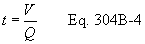
12.3 Rate of Biodegradation. Calculate the rate of biodegradation for each component with the following equation:
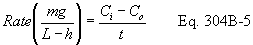
12.4 First-Order Biorate Constant. Calculate the first-order biorate constant (K1) for each component with the following equation:
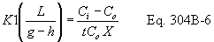
12.5 Relative Standard Deviation (RSD). Determine the standard deviation of both the influent and effluent sample concentrations (S) using the following equation:
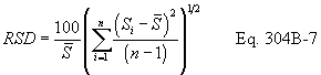
12.6 Determination of Percent Air Emissions and Percent Biodegraded. Use the results from this test method and follow the applicable procedures in appendix C of 40 CFR Part 63, entitled, “Determination of the Fraction Biodegraded (Fbio) in a Biological Treatment Unit” to determine Fbio.
13.0 Method Performance [Reserved] 14.0 Pollution Prevention [Reserved] 15.0 Waste Management [Reserved] 16.0 References1. “Guidelines for data acquisition and data quality evaluation in Environmental Chemistry”, Daniel MacDoughal, Analytical Chemistry, Volume 52, p. 2242, 1980.
2. Test Method 18, 40 CFR 60, Appendix A.
3. Standard Methods for the Examination of Water and Wastewater, 16th Edition, Method 209C, Total Suspended Solids Dried at 103-105 °C, APHA, 1985.
4. Water - 7, Hazardous Waste Treatment, Storage, and Disposal Facilities (TSDF) - Air Emission Models, U.S. Environmental Protection Agency, EPA-450/3-87-026, Review Draft, November 1989.
5. Chemdat7, Hazardous Waste Treatment, Storage, and Disposal Facilities (TSDF) - Air Emission Models, U.S. Environmental Protection Agency, EPA-450/3-87-026, Review Draft, November 1989.
17.0 Tables, Diagrams, Flowcharts, and Validation Data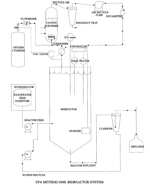 Method 305:
Measurement of Emission Potential of Individual Volatile Organic
Compounds in Waste Note:
Method 305:
Measurement of Emission Potential of Individual Volatile Organic
Compounds in Waste Note:
This method does not include all of the specifications (e.g., equipment and supplies) and procedures (e.g., sampling and analytical) essential to its performance. Some material is incorporated by reference from other methods in 40 CFR Part 60, Appendix A. Therefore, to obtain reliable results, persons using this method should have a thorough knowledge of at least Method 25D.
1.0 Scope and Application1.1 Analyte. Volatile Organics. No CAS No. assigned.
1.2 Applicability. This procedure is used to determine the emission potential of individual volatile organics (VOs) in waste.
1.3 Data Quality Objectives. Adherence to the requirements of this method will enhance the quality of the data obtained from air pollutant sampling methods.
2.0 Summary of Method2.1 The heated purge conditions established by Method 25D (40 CFR Part 60, Appendix A) are used to remove VOs from a 10 gram sample of waste suspended in a 50/50 solution of polyethylene glycol (PEG) and water. The purged VOs are quantified by using the sample collection and analytical techniques (e.g. gas chromatography) appropriate for the VOs present in the waste. The recovery efficiency of the sample collection and analytical technique is determined for each waste matrix. A correction factor is determined for each compound (if acceptable recovery criteria requirements are met of 70 to 130 percent recovery for every target compound), and the measured waste concentration is corrected with the correction factor for each compound. A minimum of three replicate waste samples shall be analyzed.
3.0 Definitions [Reserved] 4.0 Interferences [Reserved] 5.0 Safety5.1 Disclaimer. This method may involve hazardous materials, operations, and equipment. This test method may not address all of the safety problems associated with its use. It is the responsibility of the user of this test method to establish appropriate safety and health practices and to determine the applicability of regulatory limitations prior to performing this test method.
6.0 Equipment and Supplies6.1 Method 25D Purge Apparatus.
6.1.1 Purge Chamber. The purge chamber shall accommodate the 10 gram sample of waste suspended in a matrix of 50 mL of PEG and 50 mL of deionized, hydrocarbon-free water. Three fittings are used on the glass chamber top. Two #7 Ace-threads are used for the purge gas inlet and outlet connections. A #50 Ace-thread is used to connect the top of the chamber to the base (see Figure 305-1). The base of the chamber has a side-arm equipped with a #22 Sovirel fitting to allow for easy sample introductions into the chamber. The dimensions of the chamber are shown in Figure 305-1.
6.1.2 Flow Distribution Device (FDD). The FDD enhances the gas-to-liquid contact for improved purging efficiency. The FDD is a 6 mm OD (0.2 in) by 30 cm (12 in) long glass tube equipped with four arm bubblers as shown in Figure 305-1. Each arm shall have an opening of 1 mm (0.04 in) in diameter.
6.1.3 Coalescing Filter. The coalescing filter serves to discourage aerosol formation of sample gas once it leaves the purge chamber. The glass filter has a fritted disc mounted 10 cm (3.9 in) from the bottom. Two #7 Ace-threads are used for the inlet and outlet connections. The dimensions of the chamber are shown in Figure 305-2.
6.1.4 Oven. A forced convection airflow oven capable of maintaining the purge chamber and coalescing filter at 75 ±2 °C (167 ±3.6 °F).
6.1.5 Toggle Valve. An on/off valve constructed from brass or stainless steel rated to 100 psig. This valve is placed in line between the purge nitrogen source and the flow controller.
6.1.6 Flow Controller. High-quality stainless steel flow controller capable of restricting a flow of nitrogen to 6 ±0.06 L/min (0.2 ±0.002 ft 3/min) at 40 psig.
6.1.7 Polyethylene Glycol Cleaning System.
6.1.7.1 Round-Bottom Flask. One liter, three-neck glass round-bottom flask for cleaning PEG. Standard taper 24/40 joints are mounted on each neck.
6.1.7.2 Heating Mantle. Capable of heating contents of the 1-L flask to 120 °C (248 °F).
6.1.7.3 Nitrogen Bubbler. Teflon ® or glass tube, 0.25 in OD (6.35 mm).
6.1.7.4 Temperature Sensor. Partial immersion glass thermometer.
6.1.7.5 Hose Adapter. Glass with 24/40 standard tapered joint.
6.2 Volatile Organic Recovery System.
6.2.1 Splitter Valve (Optional). Stainless steel cross-pattern valve capable of splitting nominal flow rates from the purge flow of 6 L/min (0.2 ft 3/min). The valve shall be maintained at 75 + 2 °C (167 ±3.6 °F) in the heated zone and shall be placed downstream of the coalescing filter. It is recommended that 0.125 in OD (3.175 mm) tubing be used to direct the split vent flow from the heated zone. The back pressure caused by the 0.125 in OD (3.175 mm) tubing is critical for maintaining proper split valve operation.
Note:The splitter valve design is optional; it may be used in cases where the concentration of a pollutant would saturate the adsorbents.
6.2.2 Injection Port. Stainless steel 1/4 in OD (6.35 mm) compression fitting tee with a 6 mm (0.2 in) septum fixed on the top port. The injection port is the point of entry for the recovery study solution. If using a gaseous standard to determine recovery efficiency, connect the gaseous standard to the injection port of the tee.
6.2.3 Knockout Trap (Optional but Recommended). A 25 mL capacity glass reservoir body with a full-stem impinger (to avoid leaks, a modified midget glass impinger with a screw cap and ball/socket clamps on the inlet and outlet is recommended). The empty impinger is placed in an ice water bath between the injection port and the sorbent cartridge. Its purpose is to reduce the water content of the purge gas (saturated at 75 °C (167 °F)) before the sorbent cartridge.
6.2.4 Insulated Ice Bath. A 350 mL dewar or other type of insulated bath is used to maintain ice water around the knockout trap.
6.2.5 Sorbent Cartridges. Commercially available glass or stainless steel cartridge packed with one or more appropriate sorbents. The amount of adsorbent packed in the cartridge depends on the breakthrough volume of the test compounds but is limited by back pressure caused by the packing (not to exceed 7 psig). More than one sorbent cartridge placed in series may be necessary depending upon the mixture of the measured components.
6.2.6 Volumetric Glassware. Type A glass 10 mL volumetric flasks for measuring a final volume from the water catch in the knockout trap.
6.2.7 Thermal Desorption Unit. A clam-shell type oven, used for the desorption of direct thermal desorption sorbent tubes. The oven shall be capable of increasing the temperature of the desorption tubes rapidly to recommended desorption temperature.
6.2.8 Ultrasonic Bath. Small bath used to agitate sorbent material and desorption solvent. Ice water shall be used in the bath because of heat transfer caused by operation of the bath.
6.2.9 Desorption Vials. Four-dram (15 mL) capacity borosilicate glass vials with Teflon-lined caps.
6.3 Analytical System. A gas chromatograph (GC) is commonly used to separate and quantify compounds from the sample collection and recovery procedure. Method 18 (40 CFR Part 60, Appendix A) may be used as a guideline for determining the appropriate GC column and GC detector based on the test compounds to be determined. Other types of analytical instrumentation may be used (HPLC) in lieu of GC systems as long as the recovery efficiency criteria of this method are met.
6.3.1 Gas Chromatograph (GC). The GC shall be equipped with a constant-temperature liquid injection port or a heated sampling loop/valve system, as appropriate. The GC oven shall be temperature-programmable over the useful range of the GC column. The choice of detectors is based on the test compounds to be determined.
6.3.2 GC Column. Select the appropriate GC column based on (1) literature review or previous experience, (2) polarity of the analytes, (3) capacity of the column, or (4) resolving power (e.g., length, diameter, film thickness) required.
6.3.3 Data System. A programmable electronic integrator for recording, analyzing, and storing the signal generated by the detector.
7.0 Reagents and Standards7.1 Method 25D Purge Apparatus.
7.1.1 Polyethylene Glycol (PEG). Ninety-eight percent pure organic polymer with an average molecular weight of 400 g/mol. Volatile organics are removed from the PEG prior to use by heating to 120 ±5 °C (248 ±9 °F) and purging with pure nitrogen at 1 L/min (0.04 ft 3/min) for 2 hours. After purging and heating, the PEG is maintained at room temperature under a nitrogen purge maintained at 1 L/min (0.04 ft 3/min) until used. A typical apparatus used to clean the PEG is shown in Figure 305-3.
7.1.2 Water. Organic-free deionized water is required.
7.1.3 Nitrogen. High-purity nitrogen (less than 0.5 ppm total hydrocarbons) is used to remove test compounds from the purge matrix. The source of nitrogen shall be regulated continuously to 40 psig before the on/off toggle valve.
7.2 Volatile Organic Recovery System.
7.2.1 Water. Organic-free deionized water is required.
7.2.2 Desorption Solvent (when used). Appropriate high-purity (99.99 percent) solvent for desorption shall be used. Analysis shall be performed (utilizing the same analytical technique as that used in the analysis of the waste samples) on each lot to determine purity.
7.3 Analytical System. The gases required for GC operation shall be of the highest obtainable purity (hydrocarbon free). Consult the operating manual for recommended settings.
8.0 Sample Collection, Preservation, Storage, and Transport8.1 Assemble the glassware and associated fittings (see Figures 305-3 and 305-4, as appropriate) and leak-check the system (approximately 7 psig is the target pressure). After an initial leak check, mark the pressure gauge and use the initial checkpoint to monitor for leaks throughout subsequent analyses. If the pressure in the system drops below the target pressure at any time during analysis, that analysis shall be considered invalid.
8.2 Recovery Efficiency Determination. Determine the individual recovery efficiency (RE) for each of the target compounds in duplicate before the waste samples are analyzed. To determine the RE, generate a water blank (Section 11.1) and use the injection port to introduce a known volume of spike solution (or certified gaseous standard) containing all of the target compounds at the levels expected in the waste sample. Introduce the spike solution immediately after the nitrogen purge has been started (Section 8.3.2). Follow the procedures outlined in Section 8.3.3. Analyze the recovery efficiency samples using the techniques described in Section 11.2. Determine the recovery efficiency (Equation 305-1, Section 12.2) by comparing the amount of compound recovered to the theoretical amount spiked. Determine the RE twice for each compound; the relative standard deviation, (RSD) shall be ≤10 percent for each compound. If the RSD for any compound is not ≤10 percent, modify the sampling/analytical procedure and complete an RE study in duplicate, or continue determining RE until the RSD meets the acceptable criteria. The average RE shall be 0.70 ≤RE ≤1.30 for each compound. If the average RE does not meet these criteria, an alternative sample collection and/or analysis technique shall be developed and the recovery efficiency determination shall be repeated for that compound until the criteria are met for every target compound. Example modifications of the sampling/analytical system include changing the adsorbent material, changing the desorption solvent, utilizing direct thermal desorption of test compounds from the sorbent tubes, utilizing another analytical technique.
8.3 Sample Collection and Recovery.
8.3.1 The sample collection procedure in Method 25D shall be used to collect (into a preweighed vial) 10 g of waste into PEG, cool, and ship to the laboratory. Remove the sample container from the cooler and wipe the exterior to remove any ice or water. Weigh the container and sample to the nearest 0.01 g and record the weight. Pour the sample from the container into the purge flask. Rinse the sample container three times with approximately 6 mL of PEG (or the volume needed to total 50 mL of PEG in the purge flask), transferring the rinses to the purge flask. Add 50 mL of organic-free deionized water to the purge flask. Cap the purge flask tightly in between each rinse and after adding all the components into the flask.
8.3.2 Allow the oven to equilibrate to 75 ±2 °C (167 ±3.6 °F). Begin the sample recovery process by turning the toggle valve on, thus allowing a 6 L/min flow of pure nitrogen through the purge chamber.
8.3.3 Stop the purge after 30 min. Immediately remove the sorbent tube(s) from the apparatus and cap both ends. Remove the knockout trap and transfer the water catch to a 10 mL volumetric flask. Rinse the trap with organic-free deionized water and transfer the rinse to the volumetric flask. Dilute to the 10 mL mark with water. Transfer the water sample to a sample vial and store at 4 °C (39.2 °F) with zero headspace. The analysis of the contents of the water knockout trap is optional for this method. If the target compounds are water soluble, analysis of the water is recommended; meeting the recovery efficiency criteria in these cases would be difficult without adding the amount captured in the knockout trap.
9.0 Quality Control9.1 Miscellaneous Quality Control Measures.
| Section | Quality control measure | Effect |
|---|---|---|
| 8.1 | Sampling equipment leak-check | Ensures accurate measurement of sample volume. |
| 8.2 | Recovery efficiency (RE) determination for each measured compound. | Ensures accurate sample collection and analysis. |
| 8.3 | Calibration of analytical instrument with at least 3 calibration standards. | Ensures linear measurement of compounds over the instrument span. |
10.1 The analytical instrument shall be calibrated with a minimum of three levels of standards for each compound whose concentrations bracket the concentration of test compounds from the sorbent tubes. Liquid calibration standards shall be used for calibration in the analysis of the solvent extracts. The liquid calibration standards shall be prepared in the desorption solvent matrix. The calibration standards may be prepared and injected individually or as a mixture. If thermal desorption and focusing (onto another sorbent or cryogen focusing) are used, a certified gaseous mixture or a series of gaseous standards shall be used for calibration of the instrument. The gaseous standards shall be focused and analyzed in the same manner as the samples.
10.2 The analytical system shall be certified free from contaminants before a calibration is performed (see Section 11.1). The calibration standards are used to determine the linearity of the analytical system. Perform an initial calibration and linearity check by analyzing the three calibration standards for each target compound in triplicate starting with the lowest level and continuing to the highest level. If the triplicate analyses do not agree within 5 percent of their average, additional analyses will be needed until the 5 percent criteria is met. Calculate the response factor (Equation 305-3, Section 12.4) from the average area counts of the injections for each concentration level. Average the response factors of the standards for each compound. The linearity of the detector is acceptable if the response factor of each compound at a particular concentration is within 10 percent of the overall mean response factor for that compound. Analyze daily a mid-level calibration standard in duplicate and calculate a new response factor. Compare the daily response factor average to the average response factor calculated for the mid-level calibration during the initial linearity check; repeat the three-level calibration procedure if the daily average response factor differs from the initial linearity check mid-level response factor by more than 10 percent. Otherwise, proceed with the sample analysis.
11.0 Analytical Procedure11.1 Water Blank Analysis. A water blank shall be analyzed daily to determine the cleanliness of the purge and recovery system. A water blank is generated by adding 60 mL of organic-free deionized water to 50 mL of PEG in the purge chamber. Treat the blank as described in Sections 8.3.2 and 8.3.3. The purpose of the water blank is to insure that no contaminants exist in the sampling and analytical apparatus which would interfere with the quantitation of the target compounds. If contaminants are present, locate the source of contamination, remove it, and repeat the water blank analysis.
11.2 Sample Analysis. Sample analysis in the context of this method refers to techniques to remove the target compounds from the sorbent tubes, separate them using a chromatography technique, and quantify them with an appropriate detector. Two types of sample extraction techniques typically used for sorbents include solvent desorption or direct thermal desorption of test compounds to a secondary focusing unit (either sorbent or cryogen based). The test compounds are then typically transferred to a GC system for analysis. Other analytical systems may be used (e.g., HPLC) in lieu of GC systems as long as the recovery efficiency criteria of this method are met.
11.2.1 Recover the test compounds from the sorbent tubes that require solvent desorption by transferring the adsorbent material to a sample vial containing the desorption solvent. The desorption solvent shall be the same as the solvent used to prepare calibration standards. The volume of solvent depends on the amount of adsorbed material to be desorbed (1.0 mL per 100 mg of adsorbent material) and also on the amount of test compounds present. Final volume adjustment and or dilution can be made so that the concentration of test compounds in the desorption solvent is bracketed by the concentration of the calibration solutions. Ultrasonicate the desorption solvent for 15 min in an ice bath. Allow the sample to sit for a period of time so that the adsorbent material can settle to the bottom of the vial. Transfer the solvent with a pasteur pipet (minimizing the amount of adsorbent material taken) to another vial and store at 4 °C (39.2 °F).
11.2.2 Analyze the desorption solvent or direct thermal desorption tubes from each sample using the same analytical parameters used for the calibration standard. Calculate the total weight detected for each compound (Equation 305-4, Section 12.5). The slope (area/amount) and y-intercept are calculated from the line bracketed between the two closest calibration points. Correct the concentration of each waste sample with the appropriate recovery efficiency factor and the split flow ratio (if used). The final concentration of each individual test compound is calculated by dividing the corrected measured weight for that compound by the weight of the original sample determined in Section 8.3.1 (Equation 305-5, Section 12.6).
11.2.3 Repeat the analysis for the three samples collected in Section 8.3. Report the corrected concentration of each of the waste samples, average waste concentration, and relative standard deviation (Equation 305-6, Section 12.7).
12.0 Data Analysis and Calculations.12.1 Nomenclature.
AS = Mean area counts of test compound in standard. AU = Mean area counts of test compound in sample desorption solvent. b = Y-intercept of the line formed between the two closest calibration standards that bracket the concentration of the sample. CT = Amount of test compound (µg) in calibration standard. CF = Correction for adjusting final amount of sample detected for losses during individual sample runs. FP = Nitrogen flow through the purge chamber (6 L/min). FS = Nitrogen split flow directed to the sample recovery system (use 6 L/min if split flow design was not used). PPM = Final concentration of test compound in waste sample [µg/g (which is equivalent to parts per million by weight (ppmw))]. RE = Recovery efficiency for adjusting final amount of sample detected for losses due to inefficient trapping and desorption techniques. R.F. = Response factor for test compound, calculated from a calibration standard. S = Slope of the line (area counts/CT) formed between two closest calibration points that bracket the concentration of the sample. WC = Weight of test compound expected to be recovered in spike solution based on theoretical amount (µg). WE = Weight of vial and PEG (g). WF = Weight of vial, PEG and waste sample (g). WS = Weight of original waste sample (g). WT = Corrected weight of test compound measured (µg) in sample. WX = Weight of test compound measured during analysis of recovery efficiency spike samples (µg).12.2 Recovery efficiency for determining trapping/desorption efficiency of individual test compounds in the spike solution, decimal value.
12.3 Weight of waste sample (g).
12.4 Response factor for individual test compounds.
12.5 Corrected weight of a test compound in the sample, in µg.
12.6 Final concentration of a test compound in the sample in ppmw.
12.7 Relative standard deviation (RSD) calculation.
13.0 Method Performance [Reserved] 14.0 Pollution Prevention [Reserved] 15.0 Waste Management [Reserved] 16.0 References [Reserved] 17.0 Tables, Diagrams, Flowcharts, and Validation Data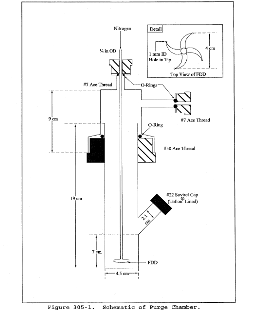
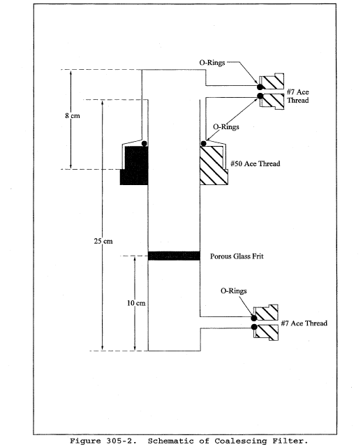
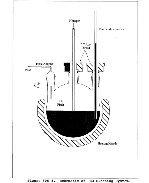
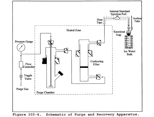 Method 306 -
Determination of Chromium Emissions From Decorative and Hard
Chromium Electroplating and Chromium Anodizing Operations -
Isokinetic Method Note:
Method 306 -
Determination of Chromium Emissions From Decorative and Hard
Chromium Electroplating and Chromium Anodizing Operations -
Isokinetic Method Note:
This method does not include all of the specifications (e.g., equipment and supplies) and procedures (e.g., sampling and analytical) essential to its performance. Some material is incorporated by reference from other methods in 40 CFR Part 60, Appendix A. Therefore, to obtain reliable results, persons using this method should have a thorough knowledge of at least Method 5.
1.0 Scope and Application1.1 Analytes.
| Analyte | CAS No. | Sensitivity |
|---|---|---|
| Chromium | 7440-47-3 | See Sec. 13.2. |
1.2 Applicability. This method applies to the determination of chromium (Cr) in emissions from decorative and hard chrome electroplating facilities, chromium anodizing operations, and continuous chromium plating operations at iron and steel facilities.
1.3 Data Quality Objectives. [Reserved]
2.0 Summary of Method2.1 Sampling. An emission sample is extracted isokinetically from the source using an unheated Method 5 sampling train (40 CFR Part 60, Appendix A), with a glass nozzle and probe liner, but with the filter omitted. The sample time shall be at least two hours. The Cr emissions are collected in an alkaline solution containing 0.1 N sodium hydroxide (NaOH) or 0.1 N sodium bicarbonate (NaHCO3). The collected samples are recovered using an alkaline solution and are then transported to the laboratory for analysis.
2.2 Analysis.
2.2.1 Total chromium samples with high chromium concentrations (≥35 µg/L) may be analyzed using inductively coupled plasma emission spectrometry (ICP) at 267.72 nm.
Note:The ICP analysis is applicable for this method only when the solution analyzed has a Cr concentration greater than or equal to 35 µg/L or five times the method detection limit as determined according to appendix B in 40 CFR part 136. Similarly, inductively coupled plasma-mass spectroscopy (ICP-MS) may be used for total chromium analysis provided the procedures for ICP-MS analysis described in Method 6020 or 6020A (EPA Office of Solid Waste, publication SW-846) are followed.
2.2.2 Alternatively, when lower total chromium concentrations (<35 µg/L) are encountered, a portion of the alkaline sample solution may be digested with nitric acid and analyzed by graphite furnace atomic absorption spectroscopy (GFAAS) at 357.9 nm.
2.2.3 If it is desirable to determine hexavalent chromium (Cr+6) emissions, the samples may be analyzed using an ion chromatograph equipped with a post-column reactor (IC/PCR) and a visible wavelength detector. To increase sensitivity for trace levels of Cr+6, a preconcentration system may be used in conjunction with the IC/PCR.
3.0 Definitions3.1 Total Chromium - measured chromium content that includes both major chromium oxidation states (Cr+3, Cr+3).
3.2 May - Implies an optional operation.
3.3 Digestion - The analytical operation involving the complete (or nearly complete) dissolution of the sample in order to ensure the complete solubilization of the element (analyte) to be measured.
3.4 Interferences - Physical, chemical, or spectral phenomena that may produce a high or low bias in the analytical result.
3.5 Analytical System - All components of the analytical process including the sample digestion and measurement apparatus.
3.6 Sample Recovery - The quantitative transfer of sample from the collection apparatus to the sample preparation (digestion, etc.) apparatus. This term should not be confused with analytical recovery.
3.7 Matrix Modifier - A chemical modification to the sample during GFAAS determinations to ensure that the analyte is not lost during the measurement process (prior to the atomization stage)
3.8 Calibration Reference Standards - Quality control standards used to check the accuracy of the instrument calibration curve prior to sample analysis.
3.9 Continuing Check Standard - Quality control standards used to verify that unacceptable drift in the measurement system has not occurred.
3.10 Calibration Blank - A blank used to verify that there has been no unacceptable shift in the baseline either immediately following calibration or during the course of the analytical measurement.
3.11 Interference Check - An analytical/measurement operation that ascertains whether a measurable interference in the sample exists.
3.12 Interelement Correction Factors - Factors used to correct for interfering elements that produce a false signal (high bias).
3.13 Duplicate Sample Analysis - Either the repeat measurement of a single solution or the measurement of duplicate preparations of the same sample. It is important to be aware of which approach is required for a particular type of measurement. For example, no digestion is required for the ICP determination and the duplicate instrument measurement is therefore adequate whereas duplicate digestion/instrument measurements are required for GFAAS.
3.14 Matrix Spiking - Analytical spikes that have been added to the actual sample matrix either before (Section 9.2.5.2) or after (Section 9.1.6). Spikes added to the sample prior to a preparation technique (e.g., digestion) allow for the assessment of an overall method accuracy while those added after only provide for the measurement accuracy determination.
4.0 Interferences4.1 ICP Interferences.
4.1.1 ICP Spectral Interferences. Spectral interferences are caused by: overlap of a spectral line from another element; unresolved overlap of molecular band spectra; background contribution from continuous or recombination phenomena; and, stray light from the line emission of high-concentrated elements. Spectral overlap may be compensated for by correcting the raw data with a computer and measuring the interfering element. At the 267.72 nm Cr analytical wavelength, iron, manganese, and uranium are potential interfering elements. Background and stray light interferences can usually be compensated for by a background correction adjacent to the analytical line. Unresolved overlap requires the selection of an alternative chromium wavelength. Consult the instrument manufacturer's operation manual for interference correction procedures.
4.1.2 ICP Physical Interferences. High levels of dissolved solids in the samples may cause significant inaccuracies due to salt buildup at the nebulizer and torch tips. This problem can be controlled by diluting the sample or by extending the rinse times between sample analyses. Standards shall be prepared in the same solution matrix as the samples (i.e., 0.1 N NaOH or 0.1 N NaHCO3).
4.1.3 ICP Chemical Interferences. These include molecular compound formation, ionization effects and solute vaporization effects, and are usually not significant in the ICP procedure, especially if the standards and samples are matrix matched.
4.2 GFAAS Interferences.
4.2.1 GFAAS Chemical Interferences. Low concentrations of calcium and/or phosphate may cause interferences; at concentrations above 200 µg/L, calcium's effect is constant and eliminates the effect of phosphate. Calcium nitrate is therefore added to the concentrated analyte to ensure a known constant effect. Other matrix modifiers recommended by the instrument manufacturer may also be considered.
4.2.2 GFAAS Cyanide Band Interferences. Nitrogen should not be used as the purge gas due to cyanide band interference.
4.2.3 GFAAS Spectral Interferences. Background correction may be required because of possible significant levels of nonspecific absorption and scattering at the 357.9 nm analytical wavelength.
4.2.4 GFAAS Background Interferences. Zeeman or Smith-Hieftje background correction is recommended for interferences resulting from high levels of dissolved solids in the alkaline impinger solutions.
4.3 IC/PCR Interferences.
4.3.1 IC/PCR Chemical Interferences. Components in the sample matrix may cause Cr+6 to convert to trivalent chromium (Cr+3) or cause Cr+3 to convert to Cr+6. The chromatographic separation of Cr+6 using ion chromatography reduces the potential for other metals to interfere with the post column reaction. For the IC/PCR analysis, only compounds that coelute with Cr+6 and affect the diphenylcarbazide reaction will cause interference.
4.3.2 IC/PCR Background Interferences. Periodic analyses of reagent water blanks are used to demonstrate that the analytical system is essentially free of contamination. Sample cross-contamination can occur when high-level and low-level samples or standards are analyzed alternately and can be eliminated by thorough purging of the sample loop. Purging of the sample can easily be achieved by increasing the injection volume to ten times the size of the sample loop.
5.0 Safety5.1 Disclaimer. This method may involve hazardous materials, operations, and equipment. This test method may not address all of the safety problems associated with its use. It is the responsibility of the user to establish appropriate safety and health practices and to determine the applicability of regulatory limitations prior to performing this test method.
5.2 Hexavalent chromium compounds have been listed as carcinogens although chromium (III) compounds show little or no toxicity. Chromium can be a skin and respiratory irritant.
6.0 Equipment and Supplies6.1 Sampling Train.
6.1.1 A schematic of the sampling train used in this method is shown in Figure 306-1. The train is the same as shown in Method 5, Section 6.0 (40 CFR Part 60, Appendix A) except that the probe liner is unheated, the particulate filter is omitted, and quartz or borosilicate glass must be used for the probe nozzle and liner in place of stainless steel.
6.1.2 Probe fittings of plastic such as Teflon, polypropylene, etc. are recommended over metal fittings to prevent contamination. If desired, a single combined probe nozzle and liner may be used, but such a single glass assembly is not a requirement of this methodology.
6.1.3 Use 0.1 N NaOH or 0.1 N NaHCO3 in the impingers in place of water.
6.1.4 Operating and maintenance procedures for the sampling train are described in APTD-0576 of Method 5. Users should read the APTD-0576 document and adopt the outlined procedures. Alternative mercury-free thermometers may be used if the thermometers are, at a minimum, equivalent in terms of performance or suitably effective for the specific temperature measurement application.
6.1.5 Similar collection systems which have been approved by the Administrator may be used.
6.2 Sample Recovery. Same as Method 5, [40 CFR Part 60, Appendix A], with the following exceptions:
6.2.1 Probe-Liner and Probe-Nozzle Brushes. Brushes are not necessary for sample recovery. If a probe brush is used, it must be non-metallic.
6.2.2 Sample Recovery Solution. Use 0.1 N NaOH or 0.1 N NaHCO3, whichever is used as the impinger absorbing solution, in place of acetone to recover the sample.
6.2.3 Sample Storage Containers. Polyethylene, with leak-free screw cap, 250 mL, 500 mL or 1,000 mL.
6.3 Analysis.
6.3.1 General. For analysis, the following equipment is needed.
6.3.1.1 Phillips Beakers. (Phillips beakers are preferred, but regular beakers may also be used.)
6.3.1.2 Hot Plate.
6.3.1.3 Volumetric Flasks. Class A, various sizes as appropriate.
6.3.1.4 Assorted Pipettes.
6.3.2 Analysis by ICP.
6.3.2.1 ICP Spectrometer. Computer-controlled emission spectrometer with background correction and radio frequency generator.
6.3.2.2 Argon Gas Supply. Welding grade or better.
6.3.3 Analysis by GFAAS.
6.3.3.1 Chromium Hollow Cathode Lamp or Electrodeless Discharge Lamp.
6.3.3.2 Graphite Furnace Atomic Absorption Spectrophotometer.
6.3.3.3 Furnace Autosampler.
6.3.4 Analysis by IC/PCR.
6.3.4.1 IC/PCR System. High performance liquid chromatograph pump, sample injection valve, post-column reagent delivery and mixing system, and a visible detector, capable of operating at 520 nm-540 nm, all with a non-metallic (or inert) flow path. An electronic peak area mode is recommended, but other recording devices and integration techniques are acceptable provided the repeatability criteria and the linearity criteria for the calibration curve described in Section 10.4 can be satisfied. A sample loading system is required if preconcentration is employed.
6.3.4.2 Analytical Column. A high performance ion chromatograph (HPIC) non-metallic column with anion separation characteristics and a high loading capacity designed for separation of metal chelating compounds to prevent metal interference. Resolution described in Section 11.6 must be obtained. A non-metallic guard column with the same ion-exchange material is recommended.
6.3.4.3 Preconcentration Column (for older instruments). An HPIC non-metallic column with acceptable anion retention characteristics and sample loading rates must be used as described in Section 11.6.
6.3.4.4 Filtration Apparatus for IC/PCR.
6.3.4.4.1 Teflon, or equivalent, filter holder to accommodate 0.45-µm acetate, or equivalent, filter, if needed to remove insoluble particulate matter.
6.3.4.4.2 0.45-µm Filter Cartridge. For the removal of insoluble material. To be used just prior to sample injection/analysis.
7.0 Reagents and Standards Note:Unless otherwise indicated, all reagents should conform to the specifications established by the Committee on Analytical Reagents of the American Chemical Society (ACS reagent grade). Where such specifications are not available, use the best available grade. Reagents should be checked by the appropriate analysis prior to field use to assure that contamination is below the analytical detection limit for the ICP or GFAAS total chromium analysis; and that contamination is below the analytical detection limit for Cr+6 using IC/PCR for direct injection or, if selected, preconcentration.
7.1 Sampling.
7.1.1 Water. Reagent water that conforms to ASTM Specification D1193-77 or 91 Type II (incorporated by reference see § 63.14). All references to water in the method refer to reagent water unless otherwise specified. It is recommended that water blanks be checked prior to preparing the sampling reagents to ensure that the Cr content is less than three (3) times the anticipated detection limit of the analytical method.
7.1.2 Sodium Hydroxide (NaOH) Absorbing Solution, 0.1 N. Dissolve 4.0 g of sodium hydroxide in 1 liter of water to obtain a pH of approximately 8.5.
7.1.3 Sodium Bicarbonate (NaHCO3) Absorbing Solution, 0.1 N. Dissolve approximately 8.5 g of sodium bicarbonate in 1 liter of water to obtain a pH of approximately 8.3.
7.1.4 Chromium Contamination.
7.1.4.1 The absorbing solution shall not exceed the QC criteria noted in Section 7.1.1 (≤3 times the instrument detection limit).
7.1.4.2 When the Cr+6 content in the field samples exceeds the blank concentration by at least a factor of ten (10), Cr+6 blank concentrations ≥10 times the detection limit will be allowed.
Note:At sources with high concentrations of acids and/or SO2, the concentration of NaOH or NaHCO3 should be ≥0.5 N to insure that the pH of the solution remains at or above 8.5 for NaOH and 8.0 for NaHCO3 during and after sampling.
7.1.5 Silica Gel. Same as in Method 5.
7.2 Sample Recovery.
7.2.1 0.1 N NaOH or 0.1 N NaHCO3. Use the same solution for the sample recovery that is used for the impinger absorbing solution.
7.2.2 pH Indicator Strip, for IC/PCR. pH indicator capable of determining the pH of solutions between the pH range of 7 and 12, at 0.5 pH increments.
7.3 Sample Preparation and Analysis.
7.3.1 Nitric Acid (HNO3), Concentrated, for GFAAS. Trace metals grade or better HNO3 must be used for reagent preparation. The ACS reagent grade HNO3 is acceptable for cleaning glassware.
7.3.2 HNO3, 1.0% (v/v), for GFAAS. Prepare, by slowly stirring, 10 mL of concentrated HNO3) into 800 mL of reagent water. Dilute to 1,000 mL with reagent water. The solution shall contain less than 0.001 mg Cr/L.
7.3.3 Calcium Nitrate Ca(NO3)2 Solution (10 µg Ca/mL) for GFAAS analysis. Prepare the solution by weighing 40.9 mg of Ca(NO3)2 into a 1 liter volumetric flask. Dilute with reagent water to 1 liter.
7.3.4 Matrix Modifier, for GFAAS. See instrument manufacturer's manual for suggested matrix modifier.
7.3.5 Chromatographic Eluent, for IC/PCR. The eluent used in the analytical system is ammonium sulfate based.
7.3.5.1 Prepare by adding 6.5 mL of 29 percent ammonium hydroxide (NH4OH) and 33 g of ammonium sulfate ((NH4)2SO4) to 500 mL of reagent water. Dilute to 1 liter with reagent water and mix well.
7.3.5.2 Other combinations of eluents and/or columns may be employed provided peak resolution, repeatability, linearity, and analytical sensitivity as described in Sections 9.3 and 11.6 are acceptable.
7.3.6 Post-Column Reagent, for IC/PCR. An effective post-column reagent for use with the chromatographic eluent described in Section 7.3.5 is a diphenylcarbazide (DPC)-based system. Dissolve 0.5 g of 1,5-diphenylcarbazide in 100 mL of ACS grade methanol. Add 500 mL of reagent water containing 50 mL of 96 percent spectrophotometric grade sulfuric acid. Dilute to 1 liter with reagent water.
7.3.7 Chromium Standard Stock Solution (1000 mg/L). Procure a certified aqueous standard or dissolve 2.829 g of potassium dichromate (K2Cr2O7), in reagent water and dilute to 1 liter.
7.3.8 Calibration Standards for ICP or IC/PCR. Prepare calibration standards for ICP or IC/PCR by diluting the Cr standard stock solution (Section 7.3.7) with 0.1 N NaOH or 0.1 N NaHCO3, whichever is used as the impinger absorbing solution, to achieve a matrix similar to the actual field samples. Suggested levels are 0, 50, 100, and 200 µg Cr/L for ICP, and 0, 1, 5, and 10 µg Cr+6/L for IC/PCR.
7.3.9 Calibration Standards for GFAAS. Chromium solutions for GFAAS calibration shall contain 1.0 percent (v/v) HNO3. The zero standard shall be 1.0 percent (v/v) HNO3. Calibration standards should be prepared daily by diluting the Cr standard stock solution (Section 7.3.7) with 1.0 percent HNO3. Use at least four standards to make the calibration curve. Suggested levels are 0, 10, 50, and 100 µg Cr/L.
7.4 Glassware Cleaning Reagents.
7.4.1 HNO3, Concentrated. ACS reagent grade or equivalent.
7.4.2 Water. Reagent water that conforms to ASTM Specification D1193-77 or 91 Type II.
7.4.3 HNO3, 10 percent (v/v). Add by stirring 500 mL of concentrated HNO3 into a flask containing approximately 4,000 mL of reagent water. Dilute to 5,000 mL with reagent water. Mix well. The reagent shall contain less than 2 µg Cr/L.
8.0 Sample Collection, Preservation, Holding Times, Storage, and Transport Note:Prior to sample collection, consideration should be given to the type of analysis (Cr+6 or total Cr) that will be performed. Which analysis option(s) will be performed will determine which sample recovery and storage procedures will be required to process the sample.
8.1 Sample Collection. Same as Method 5 (40 CFR part 60, appendix A), with the following exceptions.
8.1.1 Omit the particulate filter and filter holder from the sampling train. Use a glass nozzle and probe liner instead of stainless steel. Do not heat the probe. Place 100 mL of 0.1 N NaOH or 0.1 N NaHCO3 in each of the first two impingers, and record the data for each run on a data sheet such as shown in Figure 306-2.
8.1.2 Clean all glassware prior to sampling in hot soapy water designed for laboratory cleaning of glassware. Next, rinse the glassware three times with tap water, followed by three additional rinses with reagent water. Then soak the glassware in 10% (v/v) HNO3 solution for a minimum of 4 hours, rinse three times with reagent water, and allow to air dry. Cover all glassware openings where contamination can occur with Parafilm, or equivalent, until the sampling train is assembled for sampling.
8.1.3 Train Operation. Follow the basic procedures outlined in Method 5 in conjunction with the following instructions. Train sampling rate shall not exceed 0.030 m 3/min (1.0 cfm) during a run.
8.2 Sample Recovery. Follow the basic procedures of Method 5, with the exceptions noted.
8.2.1 A particulate filter is not recovered from this train.
8.2.2 Tester shall select either the total Cr or Cr+6 sample recovery option.
8.2.3 Samples to be analyzed for both total Cr and Cr+6, shall be recovered using the Cr+6 sample option (Section 8.2.6).
8.2.4 A field reagent blank shall be collected for either of the Cr or the Cr+6 analysis. If both analyses (Cr and Cr+6) are to be conducted on the samples, collect separate reagent blanks for each analysis.
Note:Since particulate matter is not usually present at chromium electroplating and/or chromium anodizing operations, it is not necessary to filter the Cr+6 samples unless there is observed sediment in the collected solutions. If it is necessary to filter the Cr+6 solutions, please refer to Method 0061, Determination of Hexavalent Chromium Emissions From Stationary Sources, Section 7.4, Sample Preparation in SW-846 (see Reference 1).
8.2.5 Total Cr Sample Option.
8.2.5.1 Container No. 1. Measure the volume of the liquid in the first, second, and third impingers and quantitatively transfer into a labeled sample container.
8.2.5.2 Use approximately 200 to 300 mL of the 0.1 N NaOH or 0.1 N NaHCO3 absorbing solution to rinse the probe nozzle, probe liner, three impingers, and connecting glassware; add this rinse to Container No. 1.
8.2.6 Cr+6 Sample Option.
8.2.6.1 Container No. 1. Measure and record the pH of the absorbing solution contained in the first impinger at the end of the sampling run using a pH indicator strip. The pH of the solution must be ≥8.5 for NaOH and ≥8.0 for NaHCO3. If it is not, discard the collected sample, increase the normality of the NaOH or NaHCO3 impinger absorbing solution to 0.5 N or to a solution normality approved by the Administrator and collect another air emission sample.
8.2.6.2 After determining the pH of the first impinger solution, combine and measure the volume of the liquid in the first, second, and third impingers and quantitatively transfer into the labeled sample container. Use approximately 200 to 300 mL of the 0.1 N NaOH or 0.1 N NaHCO3 absorbing solution to rinse the probe nozzle, probe liner, three impingers, and connecting glassware; add this rinse to Container No. 1.
8.2.7 Field Reagent Blank.
8.2.7.1 Container No. 2.
8.2.7.2 Place approximately 500 mL of the 0.1 N NaOH or 0.1 N NaHCO3 absorbing solution into a labeled sample container.
8.3 Sample Preservation, Storage, and Transport.
8.3.1 Total Cr Sample Option. Samples to be analyzed for total Cr need not be refrigerated.
8.3.2 Cr+6 Sample Option. Samples to be analyzed for Cr+6 must be shipped and stored at 4 °C. Allow Cr+6 samples to return to ambient temperature prior to analysis.
8.4 Sample Holding Times.
8.4.1 Total Cr Sample Option. Samples to be analyzed for total Cr shall be analyzed within 60 days of collection.
8.4.2 Cr+6 Sample Option. Samples to be analyzed for Cr+6 shall be analyzed within 14 days of collection.
9.0 Quality Control9.1 ICP Quality Control.
9.1.1 ICP Calibration Reference Standards. Prepare a calibration reference standard using the same alkaline matrix as the calibration standards; it should be at least 10 times the instrumental detection limit.
9.1.1.1 This reference standard must be prepared from a different Cr stock solution source than that used for preparation of the calibration curve standards.
9.1.1.2 Prior to sample analysis, analyze at least one reference standard.
9.1.1.3 The calibration reference standard must be measured within 10 percent of it's true value for the curve to be considered valid.
9.1.1.4 The curve must be validated before sample analyses are performed.
9.1.2 ICP Continuing Check Standard.
9.1.2.1 Perform analysis of the check standard with the field samples as described in Section 11.2 (at least after every 10 samples, and at the end of the analytical run).
9.1.2.2 The check standard can either be the mid-range calibration standard or the reference standard. The results of the check standard shall agree within 10 percent of the expected value; if not, terminate the analyses, correct the problem, recalibrate the instrument, and rerun all samples analyzed subsequent to the last acceptable check standard analysis.
9.1.3 ICP Calibration Blank.
9.1.3.1 Perform analysis of the calibration blank with the field samples as described in Section 11.2 (at least after every 10 samples, and at the end of the analytical run).
9.1.3.2 The results of the calibration blank shall agree within three standard deviations of the mean blank value. If not, analyze the calibration blank two more times and average the results. If the average is not within three standard deviations of the background mean, terminate the analyses, correct the problem, recalibrate, and reanalyze all samples analyzed subsequent to the last acceptable calibration blank analysis.
9.1.4 ICP Interference Check. Prepare an interference check solution that contains known concentrations of interfering elements that will provide an adequate test of the correction factors in the event of potential spectral interferences.
9.1.4.1 Two potential interferences, iron and manganese, may be prepared as 1000 µg/mL and 200 µg/mL solutions, respectively. The solutions should be prepared in dilute HNO3 (1-5 percent). Particular care must be used to ensure that the solutions and/or salts used to prepare the solutions are of ICP grade purity (i.e., that no measurable Cr contamination exists in the salts/solutions). Commercially prepared interfering element check standards are available.
9.1.4.2 Verify the interelement correction factors every three months by analyzing the interference check solution. The correction factors are calculated according to the instrument manufacturer's directions. If the interelement correction factors are used properly, no false Cr should be detected.
9.1.4.3 Negative results with an absolute value greater than three (3) times the detection limit are usually the results of the background correction position being set incorrectly. Scan the spectral region to ensure that the correction position has not been placed on an interfering peak.
9.1.5 ICP Duplicate Sample Analysis. Perform one duplicate sample analysis for each compliance sample batch (3 runs).
9.1.5.1 As there is no sample preparation required for the ICP analysis, a duplicate analysis is defined as a repeat analysis of one of the field samples. The selected sample shall be analyzed using the same procedures that were used to analyze the original sample.
9.1.5.2 Duplicate sample analyses shall agree within 10 percent of the original measurement value.
9.1.5.3 Report the original analysis value for the sample and report the duplicate analysis value as the QC check value. If agreement is not achieved, perform the duplicate analysis again. If agreement is not achieved the second time, perform corrective action to identify and correct the problem before analyzing the sample for a third time.
9.1.6 ICP Matrix Spiking. Spiked samples shall be prepared and analyzed daily to ensure that there are no matrix effects, that samples and standards have been matrix-matched, and that the laboratory equipment is operating properly.
9.1.6.1 Spiked sample recovery analyses should indicate a recovery for the Cr spike of between 75 and 125 percent.
9.1.6.2 Cr levels in the spiked sample should provide final solution concentrations that are within the linear portion of the calibration curve, as well as, at a concentration level at least: equal to that of the original sample; and, ten (10) times the detection limit.
9.1.6.3 If the spiked sample concentration meets the stated criteria but exceeds the linear calibration range, the spiked sample must be diluted with the field absorbing solution.
9.1.6.4 If the recoveries for the Cr spiked samples do not meet the specified criteria, perform corrective action to identify and correct the problem prior to reanalyzing the samples.
9.1.7 ICP Field Reagent Blank.
9.1.7.1 Analyze a minimum of one matrix-matched field reagent blank (Section 8.2.4) per sample batch to determine if contamination or memory effects are occurring.
9.1.7.2 If contamination or memory effects are observed, perform corrective action to identify and correct the problem before reanalyzing the samples.
9.2 GFAAS Quality Control.
9.2.1 GFAAS Calibration Reference Standards. The calibration curve must be verified by using at least one calibration reference standard (made from a reference material or other independent standard material) at or near the mid-range of the calibration curve.
9.2.1.1 The calibration curve must be validated before sample analyses are performed.
9.2.1.2 The calibration reference standard must be measured within 10 percent of its true value for the curve to be considered valid.
9.2.2 GFAAS Continuing Check Standard.
9.2.2.1 Perform analysis of the check standard with the field samples as described in Section 11.4 (at least after every 10 samples, and at the end of the analytical run).
9.2.2.2 These standards are analyzed, in part, to monitor the life and performance of the graphite tube. Lack of reproducibility or a significant change in the signal for the check standard may indicate that the graphite tube should be replaced.
9.2.2.3 The check standard may be either the mid-range calibration standard or the reference standard.
9.2.2.4 The results of the check standard shall agree within 10 percent of the expected value.
9.2.2.5 If not, terminate the analyses, correct the problem, recalibrate the instrument, and reanalyze all samples analyzed subsequent to the last acceptable check standard analysis.
9.2.3 GFAAS Calibration Blank.
9.2.3.1 Perform analysis of the calibration blank with the field samples as described in Section 11.4 (at least after every 10 samples, and at the end of the analytical run).
9.2.3.2 The calibration blank is analyzed to monitor the life and performance of the graphite tube as well as the existence of any memory effects. Lack of reproducibility or a significant change in the signal, may indicate that the graphite tube should be replaced.
9.2.3.3 The results of the calibration blank shall agree within three standard deviations of the mean blank value.
9.2.3.4 If not, analyze the calibration blank two more times and average the results. If the average is not within three standard deviations of the background mean, terminate the analyses, correct the problem, recalibrate, and reanalyze all samples analyzed subsequent to the last acceptable calibration blank analysis.
9.2.4 GFAAS Duplicate Sample Analysis. Perform one duplicate sample analysis for each compliance sample batch (3 runs).
9.2.4.1 A digested aliquot of the selected sample is processed and analyzed using the identical procedures that were used for the whole sample preparation and analytical efforts.
9.2.4.2 Duplicate sample analyses results incorporating duplicate digestions shall agree within 20 percent for sample results exceeding ten (10) times the detection limit.
9.2.4.3 Report the original analysis value for the sample and report the duplicate analysis value as the QC check value.
9.2.4.4 If agreement is not achieved, perform the duplicate analysis again. If agreement is not achieved the second time, perform corrective action to identify and correct the problem before analyzing the sample for a third time.
9.2.5 GFAAS Matrix Spiking.
9.2.5.1 Spiked samples shall be prepared and analyzed daily to ensure that (1) correct procedures are being followed, (2) there are no matrix effects and (3) all equipment is operating properly.
9.2.5.2 Cr spikes are added prior to any sample preparation.
9.2.5.3 Cr levels in the spiked sample should provide final solution concentrations that are within the linear portion of the calibration curve, as well as, at a concentration level at least: equal to that of the original sample; and, ten (10) times the detection limit.
9.2.5.4 Spiked sample recovery analyses should indicate a recovery for the Cr spike of between 75 and 125 percent.
9.2.5.5 If the recoveries for the Cr spiked samples do not meet the specified criteria, perform corrective action to identify and correct the problem prior to reanalyzing the samples.
9.2.6 GFAAS Method of Standard Additions.
9.2.6.1 Method of Standard Additions. Perform procedures in Section 5.4 of Method 12 (40 CFR Part 60, Appendix A)
9.2.6.2 Whenever sample matrix problems are suspected and standard/sample matrix matching is not possible or whenever a new sample matrix is being analyzed, perform referenced procedures to determine if the method of standard additions is necessary.
9.2.7 GFAAS Field Reagent Blank.
9.2.7.1 Analyze a minimum of one matrix-matched field reagent blank (Section 8.2.4) per sample batch to determine if contamination or memory effects are occurring.
9.2.7.2 If contamination or memory effects are observed, perform corrective action to identify and correct the problem before reanalyzing the samples.
9.3 IC/PCR Quality Control.
9.3.1 IC/PCR Calibration Reference Standards.
9.3.1.1 Prepare a calibration reference standard at a concentration that is at or near the mid-point of the calibration curve using the same alkaline matrix as the calibration standards. This reference standard should be prepared from a different Cr stock solution than that used to prepare the calibration curve standards. The reference standard is used to verify the accuracy of the calibration curve.
9.3.1.2 The curve must be validated before sample analyses are performed. Prior to sample analysis, analyze at least one reference standard with an expected value within the calibration range.
9.3.1.3 The results of this reference standard analysis must be within 10 percent of the true value of the reference standard for the calibration curve to be considered valid.
9.3.2 IC/PCR Continuing Check Standard and Calibration Blank.
9.3.2.1 Perform analysis of the check standard and the calibration blank with the field samples as described in Section 11.6 (at least after every 10 samples, and at the end of the analytical run).
9.3.2.2 The result from the check standard must be within 10 percent of the expected value.
9.3.2.3 If the 10 percent criteria is exceeded, excessive drift and/or instrument degradation may have occurred, and must be corrected before further analyses can be performed.
9.3.2.4 The results of the calibration blank analyses must agree within three standard deviations of the mean blank value.
9.3.2.5 If not, analyze the calibration blank two more times and average the results.
9.3.2.6 If the average is not within three standard deviations of the background mean, terminate the analyses, correct the problem, recalibrate, and reanalyze all samples analyzed subsequent to the last acceptable calibration blank analysis.
9.3.3 IC/PCR Duplicate Sample Analysis.
9.3.3.1 Perform one duplicate sample analysis for each compliance sample batch (3 runs).
9.3.3.2 An aliquot of the selected sample is prepared and analyzed using procedures identical to those used for the emission samples (for example, filtration and/or, if necessary, preconcentration).
9.3.3.3 Duplicate sample injection results shall agree within 10 percent for sample results exceeding ten (10) times the detection limit.
9.3.3.4 Report the original analysis value for the sample and report the duplicate analysis value as the QC check value.
9.3.3.5 If agreement is not achieved, perform the duplicate analysis again.
9.3.3.6 If agreement is not achieved the second time, perform corrective action to identify and correct the problem prior to analyzing the sample for a third time.
9.3.4 ICP/PCR Matrix Spiking. Spiked samples shall be prepared and analyzed with each sample set to ensure that there are no matrix effects, that samples and standards have been matrix-matched, and that the equipment is operating properly.
9.3.4.1 Spiked sample recovery analysis should indicate a recovery of the Cr+6 spike between 75 and 125 percent.
9.3.4.2 The spiked sample concentration should be within the linear portion of the calibration curve and should be equal to or greater than the concentration of the original sample. In addition, the spiked sample concentration should be at least ten (10) times the detection limit.
9.3.4.3 If the recoveries for the Cr+6 spiked samples do not meet the specified criteria, perform corrective action to identify and correct the problem prior to reanalyzing the samples.
9.3.5 IC/PCR Field Reagent Blank.
9.3.5.1 Analyze a minimum of one matrix-matched field reagent blank (Section 8.2.4) per sample batch to determine if contamination or memory effects are occurring.
9.3.5.2 If contamination or memory effects are observed, perform corrective action to identify and correct the problem before reanalyzing the samples.
10.0 Calibration and Standardization10.1 Sampling Train Calibration. Perform calibrations described in Method 5, (40 CFR part 60, appendix A). The alternate calibration procedures described in Method 5, may also be used.
10.2 ICP Calibration.
10.2.1 Calibrate the instrument according to the instrument manufacturer's recommended procedures, using a calibration blank and three standards for the initial calibration.
10.2.2 Calibration standards should be prepared fresh daily, as described in Section 7.3.8. Be sure that samples and calibration standards are matrix matched. Flush the system with the calibration blank between each standard.
10.2.3 Use the average intensity of multiple exposures (3 or more) for both standardization and sample analysis to reduce random error.
10.2.4 Employing linear regression, calculate the correlation coefficient .
10.2.5 The correlation coefficient must equal or exceed 0.995.
10.2.6 If linearity is not acceptable, prepare and rerun another set of calibration standards or reduce the range of the calibration standards, as necessary.
10.3 GFAAS Calibration.
10.3.1 For instruments that measure directly in concentration, set the instrument software to display the correct concentration, if applicable.
10.3.2 Curve must be linear in order to correctly perform the method of standard additions which is customarily performed automatically with most instrument computer-based data systems.
10.3.3 The calibration curve (direct calibration or standard additions) must be prepared daily with a minimum of a calibration blank and three standards that are prepared fresh daily.
10.3.4 The calibration curve acceptance criteria must equal or exceed 0.995.
10.3.5 If linearity is not acceptable, prepare and rerun another set of calibration standards or reduce the range of calibration standards, as necessary.
10.4 IC/PCR Calibration.
10.4.1 Prepare a calibration curve using the calibration blank and three calibration standards prepared fresh daily as described in Section 7.3.8.
10.4.2 The calibration curve acceptance criteria must equal or exceed 0.995.
10.4.3 If linearity is not acceptable, remake and/or rerun the calibration standards. If the calibration curve is still unacceptable, reduce the range of the curve.
10.4.4 Analyze the standards with the field samples as described in Section 11.6.
11.0 Analytical Procedures Note:The method determines the chromium concentration in µg Cr/mL. It is important that the analyst measure the field sample volume prior to analyzing the sample. This will allow for conversion of µg Cr/mL to µg Cr/sample.
11.1 ICP Sample Preparation.
11.1.1 The ICP analysis is performed directly on the alkaline impinger solution; acid digestion is not necessary, provided the samples and standards are matrix matched.
11.1.2 The ICP analysis should only be employed when the solution analyzed has a Cr concentration greater than 35 µg/L or five times the method detection limit as determined according to Appendix B in 40 CFR Part 136 or by other commonly accepted analytical procedures.
11.2 ICP Sample Analysis.
11.2.1 The ICP analysis is applicable for the determination of total chromium only.
11.2.2 ICP Blanks. Two types of blanks are required for the ICP analysis.
11.2.2.1 Calibration Blank. The calibration blank is used in establishing the calibration curve. For the calibration blank, use either 0.1 N NaOH or 0.1 N NaHCO3, whichever is used for the impinger absorbing solution. The calibration blank can be prepared fresh in the laboratory; it does not have to be prepared from the same batch of solution that was used in the field. A sufficient quantity should be prepared to flush the system between standards and samples.
11.2.2.2 Field Reagent Blank. The field reagent blank is collected in the field during the testing program. The field reagent blank (Section 8.2.4) is an aliquot of the absorbing solution prepared in Section 7.1.2. The reagent blank is used to assess possible contamination resulting from sample processing.
11.2.3 ICP Instrument Adjustment.
11.2.3.1 Adjust the ICP instrument for proper operating parameters including wavelength, background correction settings (if necessary), and interfering element correction settings (if necessary).
11.2.3.2 The instrument must be allowed to become thermally stable before beginning measurements (usually requiring at least 30 min of operation prior to calibration). During this warmup period, the optical calibration and torch position optimization may be performed (consult the operator's manual).
11.2.4 ICP Instrument Calibration.
11.2.4.1 Calibrate the instrument according to the instrument manufacturer's recommended procedures, and the procedures specified in Section 10.2.
11.2.4.2 Prior to analyzing the field samples, reanalyze the highest calibration standard as if it were a sample.
11.2.4.3 Concentration values obtained should not deviate from the actual values or from the established control limits by more than 5 percent, whichever is lower (see Sections 9.1 and 10.2).
11.2.4.4 If they do, follow the recommendations of the instrument manufacturer to correct the problem.
11.2.5 ICP Operational Quality Control Procedures.
11.2.5.1 Flush the system with the calibration blank solution for at least 1 min before the analysis of each sample or standard.
11.2.5.2 Analyze the continuing check standard and the calibration blank after each batch of 10 samples.
11.2.5.3 Use the average intensity of multiple exposures for both standardization and sample analysis to reduce random error.
11.2.6 ICP Sample Dilution.
11.2.6.1 Dilute and reanalyze samples that are more concentrated than the linear calibration limit or use an alternate, less sensitive Cr wavelength for which quality control data have already been established.
11.2.6.2 When dilutions are performed, the appropriate factors must be applied to sample measurement results.
11.2.7 Reporting Analytical Results. All analytical results should be reported in µg Cr/mL using three significant figures. Field sample volumes (mL) must be reported also.
11.3 GFAAS Sample Preparation.
11.3.1 GFAAS Acid Digestion. An acid digestion of the alkaline impinger solution is required for the GFAAS analysis.
11.3.1.1 In a beaker, add 10 mL of concentrated HNO3 to a 100 mL sample aliquot that has been well mixed. Cover the beaker with a watch glass. Place the beaker on a hot plate and reflux the sample to near dryness. Add another 5 mL of concentrated HNO3 to complete the digestion. Again, carefully reflux the sample volume to near dryness. Rinse the beaker walls and watch glass with reagent water.
11.3.1.2 The final concentration of HNO3 in the solution should be 1 percent (v/v).
11.3.1.3 Transfer the digested sample to a 50-mL volumetric flask. Add 0.5 mL of concentrated HNO3 and 1 mL of the 10 µg/mL of Ca(NO3)2. Dilute to 50 mL with reagent water.
11.3.2 HNO3 Concentration. A different final volume may be used based on the expected Cr concentration, but the HNO3 concentration must be maintained at 1 percent (v/v).
11.4 GFAAS Sample Analysis.
11.4.1 The GFAAS analysis is applicable for the determination of total chromium only.
11.4.2 GFAAS Blanks. Two types of blanks are required for the GFAAS analysis.
11.4.2.1 Calibration Blank. The 1.0 percent HNO3 is the calibration blank which is used in establishing the calibration curve.
11.4.2.2 Field Reagent Blank. An aliquot of the 0.1 N NaOH solution or the 0.1 N NaHCO3 prepared in Section 7.1.2 is collected for the field reagent blank. The field reagent blank is used to assess possible contamination resulting from processing the sample.
11.4.2.2.1 The reagent blank must be subjected to the entire series of sample preparation and analytical procedures, including the acid digestion.
11.4.2.2.2 The reagent blank's final solution must contain the same acid concentration as the sample solutions.
11.4.3 GFAAS Instrument Adjustment.
11.4.3.1 The 357.9 nm wavelength line shall be used.
11.4.3.2 Follow the manufacturer's instructions for all other spectrophotometer operating parameters.
11.4.4 Furnace Operational Parameters. Parameters suggested by the manufacturer should be employed as guidelines.
11.4.4.1 Temperature-sensing mechanisms and temperature controllers can vary between instruments and/or with time; the validity of the furnace operating parameters must be periodically confirmed by systematically altering the furnace parameters while analyzing a standard. In this manner, losses of analyte due to higher-than-necessary temperature settings or losses in sensitivity due to less than optimum settings can be minimized.
11.4.4.2 Similar verification of furnace operating parameters may be required for complex sample matrices (consult instrument manual for additional information). Calibrate the GFAAS system following the procedures specified in Section 10.3.
11.4.5 GFAAS Operational Quality Control Procedures.
11.4.5.1 Introduce a measured aliquot of digested sample into the furnace and atomize.
11.4.5.2 If the measured concentration exceeds the calibration range, the sample should be diluted with the calibration blank solution (1.0 percent HNO3) and reanalyzed.
11.4.5.3 Consult the operator's manual for suggested injection volumes. The use of multiple injections can improve accuracy and assist in detecting furnace pipetting errors.
11.4.5.4 Analyze a minimum of one matrix-matched reagent blank per sample batch to determine if contamination or any memory effects are occurring.
11.4.5.5 Analyze a calibration blank and a continuing check standard after approximately every batch of 10 sample injections.
11.4.6 GFAAS Sample Dilution.
11.4.6.1 Dilute and reanalyze samples that are more concentrated than the instrument calibration range.
11.4.6.2 If dilutions are performed, the appropriate factors must be applied to sample measurement results.
11.4.7 Reporting Analytical Results.
11.4.7.1 Calculate the Cr concentrations by the method of standard additions (see operator's manual) or, from direct calibration. All dilution and/or concentration factors must be used when calculating the results.
11.4.7.2 Analytical results should be reported in µg Cr/mL using three significant figures. Field sample volumes (mL) must be reported also.
11.5 IC/PCR Sample Preparation.
11.5.1 Sample pH. Measure and record the sample pH prior to analysis.
11.5.2 Sample Filtration. Prior to preconcentration and/or analysis, filter all field samples through a 0.45-µm filter. The filtration step should be conducted just prior to sample injection/analysis.
11.5.2.1 Use a portion of the sample to rinse the syringe filtration unit and acetate filter and then collect the required volume of filtrate.
11.5.2.2 Retain the filter if total Cr is to be determined also.
11.5.3 Sample Preconcentration (older instruments).
11.5.3.1 For older instruments, a preconcentration system may be used in conjunction with the IC/PCR to increase sensitivity for trace levels of Cr+6.
11.5.3.2 The preconcentration is accomplished by selectively retaining the analyte on a solid absorbent, followed by removal of the analyte from the absorbent (consult instrument manual).
11.5.3.3 For a manual system, position the injection valve so that the eluent displaces the concentrated Cr+6 sample, transferring it from the preconcentration column and onto the IC anion separation column.
11.6 IC/PCR Sample Analyses.
11.6.1 The IC/PCR analysis is applicable for hexavalent chromium measurements only.
11.6.2 IC/PCR Blanks. Two types of blanks are required for the IC/PCR analysis.
11.6.2.1 Calibration Blank. The calibration blank is used in establishing the analytical curve. For the calibration blank, use either 0.1 N NaOH or 0.1 N NaHCO3, whichever is used for the impinger solution. The calibration blank can be prepared fresh in the laboratory; it does not have to be prepared from the same batch of absorbing solution that is used in the field.
11.6.2.2 Field Reagent Blank. An aliquot of the 0.1 N NaOH solution or the 0.1 N NaHCO3 solution prepared in Section 7.1.2 is collected for the field reagent blank. The field reagent blank is used to assess possible contamination resulting from processing the sample.
11.6.3 Stabilized Baseline. Prior to sample analysis, establish a stable baseline with the detector set at the required attenuation by setting the eluent and post-column reagent flow rates according to the manufacturers recommendations.
Note:As long as the ratio of eluent flow rate to PCR flow rate remains constant, the standard curve should remain linear. Inject a sample of reagent water to ensure that no Cr+6 appears in the water blank.
11.6.4 Sample Injection Loop. Size of injection loop is based on standard/sample concentrations and the selected attenuator setting.
11.6.4.1 A 50-µL loop is normally sufficient for most higher concentrations.
11.6.4.2 The sample volume used to load the injection loop should be at least 10 times the loop size so that all tubing in contact with the sample is thoroughly flushed with the new sample to prevent cross contamination.
11.6.5 IC/PCR Instrument Calibration.
11.6.5.1 First, inject the calibration standards prepared, as described in Section 7.3.8 to correspond to the appropriate concentration range, starting with the lowest standard first.
11.6.5.2 Check the performance of the instrument and verify the calibration using data gathered from analyses of laboratory blanks, calibration standards, and a quality control sample.
11.6.5.3 Verify the calibration by analyzing a calibration reference standard. If the measured concentration exceeds the established value by more than 10 percent, perform a second analysis. If the measured concentration still exceeds the established value by more than 10 percent, terminate the analysis until the problem can be identified and corrected.
11.6.6 IC/PCR Instrument Operation.
11.6.6.1 Inject the calibration reference standard (as described in Section 9.3.1), followed by the field reagent blank (Section 8.2.4), and the field samples.
11.6.6.1.1 Standards (and QC standards) and samples are injected into the sample loop of the desired size (use a larger size loop for greater sensitivity). The Cr+6 is collected on the resin bed of the column.
11.6.6.1.2 After separation from other sample components, the Cr+6 forms a specific complex in the post-column reactor with the DPC reaction solution, and the complex is detected by visible absorbance at a maximum wavelength of 540 nm.
11.6.6.1.3 The amount of absorbance measured is proportional to the concentration of the Cr+6 complex formed.
11.6.6.1.4 The IC retention time and the absorbance of the Cr+6 complex with known Cr+6 standards analyzed under identical conditions must be compared to provide both qualitative and quantitative analyses.
11.6.6.1.5 If a sample peak appears near the expected retention time of the Cr+6 ion, spike the sample according to Section 9.3.4 to verify peak identity.
11.6.7 IC/PCR Operational Quality Control Procedures.
11.6.7.1 Samples should be at a pH ≥8.5 for NaOH and ≥8.0 if using NaHCO3; document any discrepancies.
11.6.7.2 Refrigerated samples should be allowed to equilibrate to ambient temperature prior to preparation and analysis.
11.6.7.3 Repeat the injection of the calibration standards at the end of the analytical run to assess instrument drift. Measure areas or heights of the Cr+6/DPC complex chromatogram peaks.
11.6.7.4 To ensure the precision of the sample injection (manual or autosampler), the response for the second set of injected standards must be within 10 percent of the average response.
11.6.7.5 If the 10 percent criteria duplicate injection cannot be achieved, identify the source of the problem and rerun the calibration standards.
11.6.7.6 Use peak areas or peak heights from the injections of calibration standards to generate a linear calibration curve. From the calibration curve, determine the concentrations of the field samples.
11.6.8 IC/PCR Sample Dilution.
11.6.8.1 Samples having concentrations higher than the established calibration range must be diluted into the calibration range and re-analyzed.
11.6.8.2 If dilutions are performed, the appropriate factors must be applied to sample measurement results.
11.6.9 Reporting Analytical Results. Results should be reported in µg Cr+6/mL using three significant figures. Field sample volumes (mL) must be reported also.
12.0 Data Analysis and Calculations12.1 Pretest Calculations.
12.1.1 Pretest Protocol (Site Test Plan).
12.1.1.1 The pretest protocol should define and address the test data quality objectives (DQOs), with all assumptions, that will be required by the end user (enforcement authority); what data are needed? why are the data needed? how will the data be used? what are method detection limits? and what are estimated target analyte levels for the following test parameters.
12.1.1.1.1 Estimated source concentration for total chromium and/or Cr+6.
12.1.1.1.2 Estimated minimum sampling time and/or volume required to meet method detection limit requirements (Appendix B 40 CFR Part 136) for measurement of total chromium and/or Cr+6.
12.1.1.1.3 Demonstrate that planned sampling parameters will meet DQOs. The protocol must demonstrate that the planned sampling parameters calculated by the tester will meet the needs of the source and the enforcement authority.
12.1.1.2 The pre-test protocol should include information on equipment, logistics, personnel, process operation, and other resources necessary for an efficient and coordinated test.
12.1.1.3 At a minimum, the pre-test protocol should identify and be approved by the source, the tester, the analytical laboratory, and the regulatory enforcement authority. The tester should not proceed with the compliance testing before obtaining approval from the enforcement authority.
12.1.2 Post Test Calculations.
12.1.2.1 Perform the calculations, retaining one extra decimal figure beyond that of the acquired data. Round off figures after final calculations.
12.1.2.2 Nomenclature.
CS = Concentration of Cr in sample solution, µg Cr/mL. Ccr = Concentration of Cr in stack gas, dry basis, corrected to standard conditions, mg/dscm. D = Digestion factor, dimension less. F = Dilution factor, dimension less. MCr = Total Cr in each sample, µg. Vad = Volume of sample aliquot after digestion, mL. Vaf = Volume of sample aliquot after dilution, mL. Vbd = Volume of sample aliquot submitted to digestion, mL. Vbf = Volume of sample aliquot before dilution, mL. VmL = Volume of impinger contents plus rinses, mL. Vm(std) = Volume of gas sample measured by the dry gas meter, corrected to standard conditions, dscm.12.1.2.3 Dilution Factor. The dilution factor is the ratio of the volume of sample aliquot after dilution to the volume before dilution. This ratio is given by the following equation:
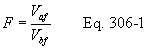
12.1.2.4 Digestion Factor. The digestion factor is the ratio of the volume of sample aliquot after digestion to the volume before digestion. This ratio is given by Equation 306-2.
12.1.2.5 Total Cr in Sample. Calculate MCr, the total µg Cr in each sample, using the following equation:

12.1.2.6 Average Dry Gas Meter Temperature and Average Orifice Pressure Drop. Same as Method 5.
12.1.2.7 Dry Gas Volume, Volume of Water Vapor, Moisture Content. Same as Method 5.
12.1.2.8 Cr Emission Concentration (CCr). Calculate CCr, the Cr concentration in the stack gas, in mg/dscm on a dry basis, corrected to standard conditions using the following equation:
12.1.2.9 Isokinetic Variation, Acceptable Results. Same as Method 5.
13.0 Method Performance13.1 Range. The recommended working range for all of the three analytical techniques starts at five times the analytical detection limit (see also Section 13.2.2). The upper limit of all three techniques can be extended indefinitely by appropriate dilution.
13.2 Sensitivity.
13.2.1 Analytical Sensitivity. The estimated instrumental detection limits listed are provided as a guide for an instrumental limit. The actual method detection limits are sample and instrument dependent and may vary as the sample matrix varies.
13.2.1.2 ICP Analytical Sensitivity. The minimum estimated detection limits for ICP, as reported in Method 6010A and the recently revised Method 6010B of SW-846 (Reference 1), are 7.0 µg Cr/L and 4.7 µg Cr/L, respectively.
13.2.1.3 GFAAS Analytical Sensitivity. The minimum estimated detection limit for GFAAS, as reported in Methods 7000A and 7191 of SW-846 (Reference 1), is 1 µg Cr/L.
13.2.1.4 IC/PCR Analytical Sensitivity. The minimum detection limit for IC/PCR with a preconcentrator, as reported in Methods 0061 and 7199 of SW-846 (Reference 1), is 0.05 µg Cr+6/L.
1.3.2.1.5 Determination of Detection Limits. The laboratory performing the Cr+6 measurements must determine the method detection limit on a quarterly basis using a suitable procedure such as that found in 40 CFR, Part 136, Appendix B. The determination should be made on samples in the appropriate alkaline matrix. Normally this involves the preparation (if applicable) and consecutive measurement of seven (7) separate aliquots of a sample with a concentration <5 times the expected detection limit. The detection limit is 3.14 times the standard deviation of these results.
13.2.2 In-stack Sensitivity. The in-stack sensitivity depends upon the analytical detection limit, the volume of stack gas sampled, the total volume of the impinger absorbing solution plus the rinses, and, in some cases, dilution or concentration factors from sample preparation. Using the analytical detection limits given in Sections 13.2.1.1, 13.2.1.2, and 13.2.1.3; a stack gas sample volume of 1.7 dscm; a total liquid sample volume of 500 mL; and the digestion concentration factor of 1/2 for the GFAAS analysis; the corresponding in-stack detection limits are 0.0014 mg Cr/dscm to 0.0021 mg Cr/dscm for ICP, 0.00015 mg Cr/dscm for GFAAS, and 0.000015 mg Cr+6/dscm for IC/PCR with preconcentration.
Note:It is recommended that the concentration of Cr in the analytical solutions be at least five times the analytical detection limit to optimize sensitivity in the analyses. Using this guideline and the same assumptions for impinger sample volume, stack gas sample volume, and the digestion concentration factor for the GFAAS analysis (500 mL,1.7 dscm, and 1/2, respectively), the recommended minimum stack concentrations for optimum sensitivity are 0.0068 mg Cr/dscm to 0.0103 mg Cr/dscm for ICP, 0.00074 mg Cr/dscm for GFAAS, and 0.000074 mg Cr+6/dscm for IC/PCR with preconcentration. If required, the in-stack detection limits can be improved by either increasing the stack gas sample volume, further reducing the volume of the digested sample for GFAAS, improving the analytical detection limits, or any combination of the three.
13.3 Precision.
13.3.1 The following precision data have been reported for the three analytical methods. In each case, when the sampling precision is combined with the reported analytical precision, the resulting overall precision may decrease.
13.3.2 Bias data is also reported for GFAAS.
13.4 ICP Precision.
13.4.1 As reported in Method 6010B of SW-846 (Reference 1), in an EPA round-robin Phase 1 study, seven laboratories applied the ICP technique to acid/distilled water matrices that had been spiked with various metal concentrates. For true values of 10, 50, and 150 µg Cr/L; the mean reported values were 10, 50, and 149 µg Cr/L; and the mean percent relative standard deviations were 18, 3.3, and 3.8 percent, respectively.
13.4.2 In another multi laboratory study cited in Method 6010B, a mean relative standard of 8.2 percent was reported for an aqueous sample concentration of approximately 3750 µg Cr/L.
13.5 GFAAS Precision. As reported in Method 7191 of SW-846 (Reference 1), in a single laboratory (EMSL), using Cincinnati, Ohio tap water spiked at concentrations of 19, 48, and 77 µg Cr/L, the standard deviations were ±0.1, ±0.2, and ±0.8, respectively. Recoveries at these levels were 97 percent, 101 percent, and 102 percent, respectively.
13.6 IC/PCR Precision. As reported in Methods 0061 and 7199 of SW-846 (Reference 1), the precision of IC/PCR with sample preconcentration is 5 to 10 percent. The overall precision for sewage sludge incinerators emitting 120 ng/dscm of Cr+6 and 3.5 µg/dscm of total Cr was 25 percent and 9 percent, respectively; and for hazardous waste incinerators emitting 300 ng/dscm of C+6 the precision was 20 percent.
14.0 Pollution Prevention14.1 The only materials used in this method that could be considered pollutants are the chromium standards used for instrument calibration and acids used in the cleaning of the collection and measurement containers/labware, in the preparation of standards, and in the acid digestion of samples. Both reagents can be stored in the same waste container.
14.2 Cleaning solutions containing acids should be prepared in volumes consistent with use to minimize the disposal of excessive volumes of acid.
14.3 To the extent possible, the containers/vessels used to collect and prepare samples should be cleaned and reused to minimize the generation of solid waste.
15.0 Waste Management15.1 It is the responsibility of the laboratory and the sampling team to comply with all federal, state, and local regulations governing waste management, particularly the discharge regulations, hazardous waste identification rules, and land disposal restrictions; and to protect the air, water, and land by minimizing and controlling all releases from field operations.
15.2 For further information on waste management, consult The Waste Management Manual for Laboratory Personnel and Less is Better - Laboratory Chemical Management for Waste Reduction, available from the American Chemical Society's Department of Government Relations and Science Policy, 1155 16th Street NW, Washington, DC 20036.
16.0 References1. “Test Methods for Evaluating Solid Waste, Physical/Chemical Methods, SW-846, Third Edition,” as amended by Updates I, II, IIA, IIB, and III. Document No. 955-001-000001. Available from Superintendent of Documents, U.S. Government Printing Office, Washington, DC, November 1986.
2. Cox, X.B., R.W. Linton, and F.E. Butler. Determination of Chromium Speciation in Environmental Particles - A Multi-technique Study of Ferrochrome Smelter Dust. Accepted for publication in Environmental Science and Technology.
3. Same as Section 17.0 of Method 5, References 2, 3, 4, 5, and 7.
4. California Air Resources Board, “Determination of Total Chromium and Hexavalent Chromium Emissions from Stationary Sources.” Method 425, September 12, 1990.
5. The Merck Index. Eleventh Edition. Merck & Co., Inc., 1989.
6. Walpole, R.E., and R.H. Myers. “Probability and Statistics for Scientists and Engineering.” 3rd Edition. MacMillan Publishing Co., NewYork, N.Y., 1985.
17.0 Tables, Diagrams, Flowcharts, and Validation Data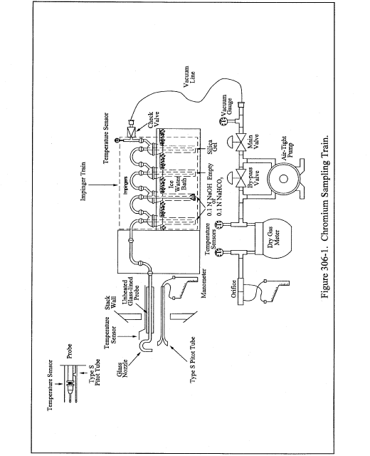
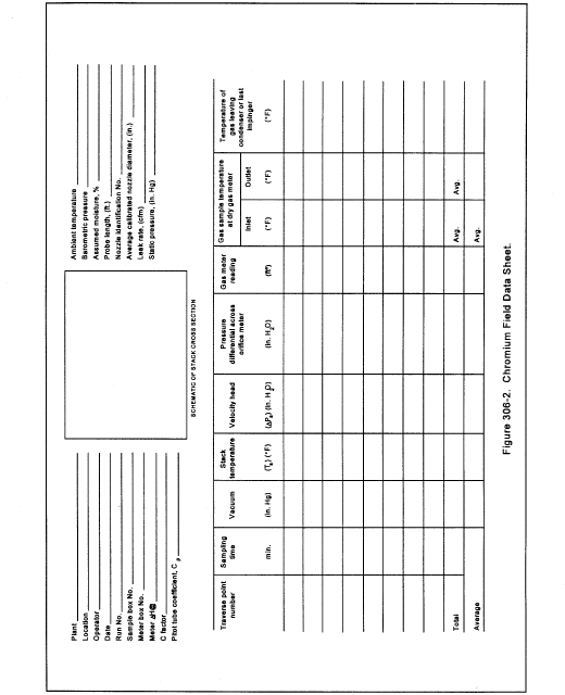 Method 306A -
Determination of Chromium Emissions From Decorative and Hard
Chromium Electroplating and Chromium Anodizing Operations Note:
Method 306A -
Determination of Chromium Emissions From Decorative and Hard
Chromium Electroplating and Chromium Anodizing Operations Note:
This method does not include all of the specifications (e.g., equipment and supplies) and procedures (e.g., sampling and analytical) essential to its performance. Some material is incorporated by reference from other methods in 40 CFR Part 60, Appendix A and in this part. Therefore, to obtain reliable results, persons using this method should have a thorough knowledge of at least Methods 5 and 306.
1.0 Scope and Application1.1 Analyte. Chromium. CAS Number (7440-47-3).
1.2 Applicability.
1.2.1 This method applies to the determination of chromium (Cr) in emissions from decorative and hard chromium electroplating facilities, chromium anodizing operations, and continuous chromium plating at iron and steel facilities. The method is less expensive and less complex to conduct than Method 306. Correctly applied, the precision and bias of the sample results should be comparable to those obtained with the isokinetic Method 306. This method is applicable for the determination of air emissions under nominal ambient moisture, temperature, and pressure conditions.
1.2.2 The method is also applicable to electroplating and anodizing sources controlled by wet scrubbers.
1.3 Data Quality Objectives.
1.3.1 Pretest Protocol.
1.3.1.1 The pretest protocol should define and address the test data quality objectives (DQOs), with all assumptions, that will be required by the end user (enforcement authority); what data are needed? why are the data needed? how will data be used? what are method detection limits? and what are estimated target analyte levels for the following test parameters.
1.3.1.1.1 Estimated source concentration for total chromium and/or Cr+6.
1.3.1.1.2 Estimated minimum sampling time and/or volume required to meet method detection limit requirements (Appendix B 40 CFR Part 136) for measurement of total chromium and/or Cr+6.
1.3.1.1.3 Demonstrate that planned sampling parameters will meet DQOs. The protocol must demonstrate that the planned sampling parameters calculated by the tester will meet the needs of the source and the enforcement authority.
1.3.1.2 The pre-test protocol should include information on equipment, logistics, personnel, process operation, and other resources necessary for an efficient and coordinated performance test.
1.3.1.3 At a minimum, the pre-test protocol should identify and be approved by the source, the tester, the analytical laboratory, and the regulatory enforcement authority. The tester should not proceed with the compliance testing before obtaining approval from the enforcement authority.
2.0 Summary of Method2.1 Sampling.
2.1.1 An emission sample is extracted from the source at a constant sampling rate determined by a critical orifice and collected in a sampling train composed of a probe and impingers. The proportional sampling time at the cross sectional traverse points is varied according to the stack gas velocity at each point. The total sample time must be at least two hours.
2.1.2 The chromium emission concentration is determined by the same analytical procedures described in Method 306: inductively-coupled plasma emission spectrometry (ICP), graphite furnace atomic absorption spectrometry (GFAAS), or ion chromatography with a post-column reactor (IC/PCR).
2.1.2.1 Total chromium samples with high chromium concentrations (≥35 µg/L) may be analyzed using inductively coupled plasma emission spectrometry (ICP) at 267.72 nm.
Note:The ICP analysis is applicable for this method only when the solution analyzed has a Cr concentration greater than or equal to 35 µg/L or five times the method detection limit as determined according to Appendix B in 40 CFR Part 136.
2.1.2.2 Alternatively, when lower total chromium concentrations (<35 µg/L) are encountered, a portion of the alkaline sample solution may be digested with nitric acid and analyzed by graphite furnace atomic absorption spectroscopy (GFAAS) at 357.9 nm.
2.1.2.3 If it is desirable to determine hexavalent chromium (Cr+6) emissions, the samples may be analyzed using an ion chromatograph equipped with a post-column reactor (IC/PCR) and a visible wavelength detector. To increase sensitivity for trace levels of Cr+6, a preconcentration system may be used in conjunction with the IC/PCR.
3.0 Definitions3.1 Total Chromium - measured chromium content that includes both major chromium oxidation states (Cr + 3, Cr + 6).
3.2 May - Implies an optional operation.
3.3 Digestion - The analytical operation involving the complete (or nearly complete) dissolution of the sample in order to ensure the complete solubilization of the element (analyte) to be measured.
3.4 Interferences - Physical, chemical, or spectral phenomena that may produce a high or low bias in the analytical result.
3.5 Analytical System - All components of the analytical process including the sample digestion and measurement apparatus.
3.6 Sample Recovery - The quantitative transfer of sample from the collection apparatus to the sample preparation (digestion, etc.) apparatus. This term should not be confused with analytical recovery.
4.0 Interferences4.1 Same as in Method 306, Section 4.0.
5.0 Safety5.1 Disclaimer. This method may involve hazardous materials, operations, and equipment. This test method does not purport to address all of the safety issues associated with its use. It is the responsibility of the user to establish appropriate safety and health practices and to determine the applicability of regulatory limitations prior to performing this test method.
5.2 Chromium and some chromium compounds have been listed as carcinogens although Chromium (III) compounds show little or no toxicity. Chromium is a skin and respiratory irritant.
6.0 Equipment and Supplies Note:Mention of trade names or specific products does not constitute endorsement by the Environmental Protection Agency.
6.1 Sampling Train. A schematic of the sampling train is shown in Figure 306A-1. The individual components of the train are available commercially, however, some fabrication and assembly are required.
6.1.1 Probe Nozzle/Tubing and Sheath.
6.1.1.1 Use approximately 6.4-mm ( 1/4-in.) inside diameter (ID) glass or rigid plastic tubing approximately 20 cm (8 in.) in length with a short 90 degree bend at one end to form the sampling nozzle. Grind a slight taper on the nozzle end before making the bend. Attach the nozzle to flexible tubing of sufficient length to enable collection of a sample from the stack.
6.1.1.2 Use a straight piece of larger diameter rigid tubing (such as metal conduit or plastic water pipe) to form a sheath that begins about 2.5 cm (1 in.) from the 90 ° bend on the nozzle and encases and supports the flexible tubing.
6.1.2 Type S Pitot Tube. Same as Method 2, Section 6.1 (40 CFR Part 60, Appendix A).
6.1.3 Temperature Sensor.
6.1.3.1 A thermocouple, liquid-filled bulb thermometer, bimetallic thermometer, mercury-in-glass thermometer, or other sensor capable of measuring temperature to within 1.5 percent of the minimum absolute stack temperature.
6.1.3.2 The temperature sensor shall either be positioned near the center of the stack, or be attached to the pitot tube as directed in Section 6.3 of Method 2.
6.1.4 Sample Train Connectors.
6.1.4.1 Use thick wall flexible plastic tubing (polyethylene, polypropylene, or polyvinyl chloride) ∼ 6.4-mm ( 1/4-in.) to 9.5-mm ( 3/8-in.) ID to connect the train components.
6.1.4.2 A combination of rigid plastic tubing and thin wall flexible tubing may be used as long as tubing walls do not collapse when leak-checking the train. Metal tubing cannot be used.
6.1.5 Impingers. Three, one-quart capacity, glass canning jars with vacuum seal lids, or three Greenburg-Smith (GS) design impingers connected in series, or equivalent, may be used.
6.1.5.1 One-quart glass canning jar. Three separate jar containers are required: (1) the first jar contains the absorbing solution; (2) the second is empty and is used to collect any reagent carried over from the first container; and (3) the third contains the desiccant drying agent.
6.1.5.2 Canning Jar Connectors. The jar containers are connected by leak-tight inlet and outlet tubes installed in the lids of each container for assembly with the train. The tubes may be made of ∼ 6.4 mm ( 1/4-in.) ID glass or rigid plastic tubing. For the inlet tube of the first impinger, heat the glass or plastic tubing and draw until the tubing separates. Fabricate the necked tip to form an orifice tip that is approximately 2.4 mm ( 3/32-in.) ID.
6.1.5.2.1 When assembling the first container, place the orifice tip end of the tube approximately 4.8 mm ( 3/16-in.) above the inside bottom of the jar.
6.1.5.2.2 For the second container, the inlet tube need not be drawn and sized, but the tip should be approximately 25 mm (1 in.) above the bottom of the jar.
6.1.5.2.3 The inlet tube of the third container should extend to approximately 12.7 mm ( 1/2-in.) above the bottom of the jar.
6.1.5.2.4 Extend the outlet tube for each container approximately 50 mm (2 in.) above the jar lid and downward through the lid, approximately 12.7 mm ( 1/2-in.) beneath the bottom of the lid.
6.1.5.3 Greenburg-Smith Impingers. Three separate impingers of the Greenburg-Smith (GS) design as described in Section 6.0 of Method 5 are required. The first GS impinger shall have a standard tip (orifice/plate), and the second and third GS impingers shall be modified by replacing the orifice/plate tube with a 13 mm ( 1/2-in.) ID glass tube, having an unrestricted opening located 13 mm ( 1/2-in.) from the bottom of the outer flask.
6.1.5.4 Greenburg-Smith Connectors. The GS impingers shall be connected by leak-free ground glass “U” tube connectors or by leak-free non-contaminating flexible tubing. The first impinger shall contain the absorbing solution, the second is empty and the third contains the desiccant drying agent.
6.1.6 Manometer. Inclined/vertical type, or equivalent device, as described in Section 6.2 of Method 2 (40 CFR Part 60, Appendix A).
6.1.7 Critical Orifice. The critical orifice is a small restriction in the sample line that is located upstream of the vacuum pump. The orifice produces a constant sampling flow rate that is approximately 0.021 cubic meters per minute (m3/min) or 0.75 cubic feet per minute (cfm).
6.1.7.1 The critical orifice can be constructed by sealing a 2.4-mm ( 3/32-in.) ID brass tube approximately 14.3 mm ( 9/16-in.) in length inside a second brass tube that is approximately 8 mm ( 5/16-in.) ID and 14.3-mm ( 9/16-in.) in length .
6.1.7.2 Materials other than brass can be used to construct the critical orifice as long as the flow through the sampling train can be maintained at approximately 0.021 cubic meter per minute (0.75) cfm.
6.1.8 Connecting Hardware. Standard pipe and fittings, 9.5-mm ( 3/8-in.), 6.4-mm ( 1/4-in.) or 3.2-mm ( 1/8-in.) ID, may be used to assemble the vacuum pump, dry gas meter and other sampling train components.
6.1.9 Vacuum Gauge. Capable of measuring approximately 760 mm Hg (30 in. Hg) vacuum in 25.4 mm HG (1 in. Hg) increments. Locate vacuum gauge between the critical orifice and the vacuum pump.
6.1.10 Pump Oiler. A glass oil reservoir with a wick mounted at the vacuum pump inlet that lubricates the pump vanes. The oiler should be an in-line type and not vented to the atmosphere. See EMTIC Guideline Document No. GD-041.WPD for additional information.
6.1.11 Vacuum Pump. Gast Model 0522-V103-G18DX, or equivalent, capable of delivering at least 1.5 cfm at 15 in. Hg vacuum.
6.1.12 Oil Trap/Muffler. An empty glass oil reservoir without wick mounted at the pump outlet to control the pump noise and prevent oil from reaching the dry gas meter.
6.1.13 By-pass Fine Adjust Valve (Optional). Needle valve assembly 6.4-mm ( 1/4-in.), Whitey 1 RF 4-A, or equivalent, that allows for adjustment of the train vacuum.
6.1.13.1 A fine-adjustment valve is positioned in the optional pump by-pass system that allows the gas flow to recirculate through the pump. This by-pass system allows the tester to control/reduce the maximum leak-check vacuum pressure produced by the pump.
6.1.13.1.1 The tester must conduct the post test leak check at a vacuum equal to or greater than the maximum vacuum encountered during the sampling run.
6.1.13.1.2 The pump by-pass assembly is not required, but is recommended if the tester intends to leak-check the 306A train at the vacuum experienced during a run.
6.1.14 Dry Gas Meter. An Equimeter Model 110 test meter or, equivalent with temperature sensor(s) installed (inlet/outlet) to monitor the meter temperature. If only one temperature sensor is installed, locate the sensor at the outlet side of the meter. The dry gas meter must be capable of measuring the gaseous volume to within ±2% of the true volume.
Note:The Method 306 sampling train is also commercially available and may be used to perform the Method 306A tests. The sampling train may be assembled as specified in Method 306A with the sampling rate being operated at the delta H@ specified for the calibrated orifice located in the meter box. The Method 306 train is then operated as described in Method 306A.
6.2 Barometer. Mercury aneroid barometer, or other barometer equivalent, capable of measuring atmospheric pressure to within ±2.5 mm Hg (0.1 in. Hg).
6.2.1 A preliminary check of the barometer shall be made against a mercury-in-glass reference barometer or its equivalent.
6.2.2 Tester may elect to obtain the absolute barometric pressure from a nearby National Weather Service station.
6.2.2.1 The station value (which is the absolute barometric pressure) must be adjusted for elevation differences between the weather station and the sampling location. Either subtract 2.5 mm Hg (0.1 in. Hg) from the station value per 30 m (100 ft) of elevation increase or add the same for an elevation decrease.
6.2.2.2 If the field barometer cannot be adjusted to agree within 0.1 in. Hg of the reference barometric, repair or discard the unit. The barometer pressure measurement shall be recorded on the sampling data sheet.
6.3 Sample Recovery. Same as Method 5, Section 6.2 (40 CFR Part 60, Appendix A), with the following exceptions:
6.3.1 Probe-Liner and Probe-Nozzle Brushes. Brushes are not necessary for sample recovery. If a probe brush is used, it must be non-metallic.
6.3.2 Wash Bottles. Polyethylene wash bottle, for sample recovery absorbing solution.
6.3.3 Sample Recovery Solution. Use 0.1 N NaOH or 0.1 N NaHCO3, whichever is used as the impinger absorbing solution, to replace the acetone.
6.3.4 Sample Storage Containers.
6.3.4.1 Glass Canning Jar. The first canning jar container of the sampling train may serve as the sample shipping container. A new lid and sealing plastic wrap shall be substituted for the container lid assembly.
6.3.4.2 Polyethylene or Glass Containers. Transfer the Greenburg-Smith impinger contents to precleaned polyethylene or glass containers. The samples shall be stored and shipped in 250-mL, 500-mL or 1000-mL polyethylene or glass containers with leak-free, non metal screw caps.
6.3.5 pH Indicator Strip, for Cr +6 Samples. pH indicator strips, or equivalent, capable of determining the pH of solutions between the range of 7 and 12, at 0.5 pH increments.
6.3.6 Plastic Storage Containers. Air tight containers to store silica gel.
6.4 Analysis. Same as Method 306, Section 6.3.
7.0 Reagents and Standards. Note:Unless otherwise indicated, all reagents shall conform to the specifications established by the Committee on Analytical Reagents of the American Chemical Society (ACS reagent grade). Where such specifications are not available, use the best available grade. It is recommended, but not required, that reagents be checked by the appropriate analysis prior to field use to assure that contamination is below the analytical detection limit for the ICP or GFAAS total chromium analysis; and that contamination is below the analytical detection limit for Cr+6 using IC/PCR for direct injection or, if selected, preconcentration.
7.1 Sampling.
7.1.1 Water. Reagent water that conforms to ASTM Specification D1193 Type II (incorporated by reference see § 63.14). All references to water in the method refer to reagent water unless otherwise specified. It is recommended that water blanks be checked prior to preparing the sampling reagents to ensure that the Cr content is less than three (3) times the anticipated detection limit of the analytical method.
7.1.2 Sodium Hydroxide (NaOH) Absorbing Solution, 0.1 N. Dissolve 4.0 g of sodium hydroxide in 1 liter of water to obtain a pH of approximately 8.5.
7.1.3 Sodium Bicarbonate (NaHCO3) Absorbing Solution, 0.1 N. Dissolve approximately 8.5 g of sodium bicarbonate in 1 liter of water to obtain a pH of approximately 8.3.
7.1.4 Chromium Contamination.
7.1.4.1 The absorbing solution shall not exceed the QC criteria noted in Method 306, Section 7.1.1 (≤3 times the instrument detection limit).
7.1.4.2 When the Cr+6 content in the field samples exceeds the blank concentration by at least a factor of ten (10), Cr+6 blank levels ≤10 times the detection limit will be allowed.
Note:At sources with high concentrations of acids and/or SO2, the concentration of NaOH or NaHCO3 should be ≥0.5 N to insure that the pH of the solution remains at or above 8.5 for NaOH and 8.0 for NaHCO3 during and after sampling.
7.1.3 Desiccant. Silica Gel, 6-16 mesh, indicating type. Alternatively, other types of desiccants may be used, subject to the approval of the Administrator.
7.2 Sample Recovery. Same as Method 306, Section 7.2.
7.3 Sample Preparation and Analysis. Same as Method 306, Section 7.3.
7.4 Glassware Cleaning Reagents. Same as Method 306, Section 7.4.
8.0 Sample Collection, Recovery, Preservation, Holding Times, Storage, and Transport Note:Prior to sample collection, consideration should be given as to the type of analysis (Cr+6 or total Cr) that will be performed. Deciding which analysis will be performed will enable the tester to determine which appropriate sample recovery and storage procedures will be required to process the sample.
8.1 Sample Collection.
8.1.1 Pretest Preparation.
8.1.1.1 Selection of Measurement Site. Locate the sampling ports as specified in Section 11.0 of Method 1 (40 CFR Part 60, Appendix A).
8.1.1.2 Location of Traverse Points.
8.1.1.2.1 Locate the traverse points as specified in Section 11.0 of Method 1 (40 CFR Part 60, Appendix A). Use a total of 24 sampling points for round ducts and 24 or 25 points for rectangular ducts. Mark the pitot and sampling probe to identify the sample traversing points.
8.1.1.2.2 For round ducts less than 12 inches in diameter, use a total of 16 points.
8.1.1.3 Velocity Pressure Traverse. Perform an initial velocity traverse before obtaining samples. The Figure 306A-2 data sheet may be used to record velocity traverse data.
8.1.1.3.1 To demonstrate that the flow rate is constant over several days of testing, perform complete traverses at the beginning and end of each day's test effort, and calculate the deviation of the flow rate for each daily period. The beginning and end flow rates are considered constant if the deviation does not exceed 10 percent. If the flow rate exceeds the 10 percent criteria, either correct the inconsistent flow rate problem, or obtain the Administrator's approval for the test results.
8.1.1.3.2 Perform traverses as specified in Section 8.0 of Method 2, but record only the Δp (velocity pressure) values for each sampling point. If a mass emission rate is desired, stack velocity pressures shall be recorded before and after each test, and an average stack velocity pressure determined for the testing period.
8.1.1.4 Verification of Absence of Cyclonic Flow. Check for cyclonic flow during the initial traverse to verify that it does not exist. Perform the cyclonic flow check as specified in Section 11.4 of Method 1 (40 CFR Part 60, Appendix A).
8.1.1.4.1 If cyclonic flow is present, verify that the absolute average angle of the tangential flow does not exceed 20 degrees. If the average value exceeds 20 degrees at the sampling location, the flow condition in the stack is unacceptable for testing.
8.1.1.4.2 Alternative procedures, subject to approval of the Administrator, e.g., installing straightening vanes to eliminate the cyclonic flow, must be implemented prior to conducting the testing.
8.1.1.5 Stack Gas Moisture Measurements. Not required. Measuring the moisture content is optional when a mass emission rate is to be calculated.
8.1.1.5.1 The tester may elect to either measure the actual stack gas moisture during the sampling run or utilize a nominal moisture value of 2 percent.
8.1.1.5.2 For additional information on determining sampling train moisture, please refer to Method 4 (40 CFR Part 60, Appendix A).
8.1.1.6 Stack Temperature Measurements. If a mass emission rate is to be calculated, a temperature sensor must be placed either near the center of the stack, or attached to the pitot tube as described in Section 8.3 of Method 2. Stack temperature measurements, shall be recorded before and after each test, and an average stack temperature determined for the testing period.
8.1.1.7 Point Sampling Times. Since the sampling rate of the train (0.75 cfm) is maintained constant by the critical orifice, it is necessary to calculate specific sampling times for each traverse point in order to obtain a proportional sample.
8.1.1.7.1 If the sampling period (3 runs) is to be completed in a single day, the point sampling times shall be calculated only once.
8.1.1.7.2 If the sampling period is to occur over several days, the sampling times must be calculated daily using the initial velocity pressure data recorded for that day. Determine the average of the Δp values obtained during the velocity traverse (Figure 306A-2).
8.1.1.7.3 If the stack diameter is less than 12 inches, use 7.5 minutes in place of 5 minutes in the equation and 16 sampling points instead of 24 or 25 points. Calculate the sampling times for each traverse point using the following equation:
Where: n = Sampling point number. Δp = Average pressure differential across pitot tube, mm H2O (in. H2O). ΔPavg = Average of Δp values, mm H2O (in. H2O). Note:Convert the decimal fractions for minutes to seconds.
8.1.1.8 Pretest Preparation. It is recommended, but not required, that all items which will be in contact with the sample be cleaned prior to performing the testing to avoid possible sample contamination (positive chromium bias). These items include, but are not limited to: Sampling probe, connecting tubing, impingers, and jar containers.
8.1.1.8.1 Sample train components should be: (1) Rinsed with hot tap water; (2) washed with hot soapy water; (3) rinsed with tap water; (4) rinsed with reagent water; (5) soaked in a 10 percent (v/v) nitric acid solution for at least four hours; and (6) rinsed throughly with reagent water before use.
8.1.1.8.2 At a minimum, the tester should, rinse the probe, connecting tubing, and first and second impingers twice with either 0.1 N sodium hydroxide (NaOH) or 0.1 N sodium bicarbonate (NaHCO3) and discard the rinse solution.
8.1.1.8.3 If separate sample shipping containers are to be used, these also should be precleaned using the specified cleaning procedures.
8.1.1.9 Preparation of Sampling Train. Assemble the sampling train as shown in Figure 306A-1. Secure the nozzle-liner assembly to the outer sheath to prevent movement when sampling.
8.1.1.9.1 Place 250 mL of 0.1 N NaOH or 0.1 N NaHCO3 absorbing solution into the first jar container or impinger. The second jar/impinger is to remain empty. Place 6 to 16 mesh indicating silica gel, or equivalent desiccant into the third jar/impinger until the container is half full (∼ 300 to 400 g).
8.1.1.9.2 Place a small cotton ball in the outlet exit tube of the third jar to collect small silica gel particles that may dislodge and impair the pump and/or gas meter.
8.1.1.10 Pretest Leak-Check. A pretest leak-check is recommended, but not required. If the tester opts to conduct the pretest leak-check, the following procedures shall be performed: (1) Place the jar/impinger containers into an ice bath and wait 10 minutes for the ice to cool the containers before performing the leak check and/or start sampling; (2) to perform the leak check, seal the nozzle using a piece of clear plastic wrap placed over the end of a finger and switch on the pump; and (3) the train system leak rate should not exceed 0.02 cfm at a vacuum of 380 mm Hg (15 in. Hg) or greater. If the leak rate does exceed the 0.02 cfm requirement, identify and repair the leak area and perform the leak check again.
Note:Use caution when releasing the vacuum following the leak check. Always allow air to slowly flow through the nozzle end of the train system while the pump is still operating. Switching off the pump with vacuum on the system may result in the silica gel being pulled into the second jar container.
8.1.1.11 Leak-Checks During Sample Run. If, during the sampling run, a component (e.g., jar container) exchange becomes necessary, a leak-check shall be conducted immediately before the component exchange is made. The leak-check shall be performed according to the procedure outlined in Section 8.1.1.10 of this method. If the leakage rate is found to be ≤0.02 cfm at the maximum operating vacuum, the results are acceptable. If, however, a higher leak rate is obtained, either record the leakage rate and correct the sample volume as shown in Section 12.3 of Method 5 or void the sample and initiate a replacement run. Following the component change, leak-checks are optional, but are recommended as are the pretest leak-checks.
8.1.1.12 Post Test Leak Check. Remove the probe assembly and flexible tubing from the first jar/impinger container. Seal the inlet tube of the first container using clear plastic wrap and switch on the pump. The vacuum in the line between the pump and the critical orifice must be ≥15 in. Hg. Record the vacuum gauge measurement along with the leak rate observed on the train system.
8.1.1.12.1 If the leak rate does not exceed 0.02 cfm, the results are acceptable and no sample volume correction is necessary.
8.1.1.12.2 If, however, a higher leak rate is obtained (>0.02 cfm), the tester shall either record the leakage rate and correct the sample volume as shown in Section 12.3 of Method 5, or void the sampling run and initiate a replacement run. After completing the leak-check, slowly release the vacuum at the first container while the pump is still operating. Afterwards, switch-off the pump.
8.1.2 Sample Train Operation.
8.1.2.1 Data Recording. Record all pertinent process and sampling data on the data sheet (see Figure 306A-3). Ensure that the process operation is suitable for sample collection.
8.1.2.2 Starting the Test. Place the probe/nozzle into the duct at the first sampling point and switch on the pump. Start the sampling using the time interval calculated for the first point. When the first point sampling time has been completed, move to the second point and continue to sample for the time interval calculated for that point; sample each point on the traverse in this manner. Maintain ice around the sample containers during the run.
8.1.2.3 Critical Flow. The sample line between the critical orifice and the pump must operate at a vacuum of ≥380 mm Hg (≥15 in. Hg) in order for critical flow to be maintained. This vacuum must be monitored and documented using the vacuum gauge located between the critical orifice and the pump.
Note:Theoretically, critical flow for air occurs when the ratio of the orifice outlet absolute pressure to the orifice inlet absolute pressure is less than a factor of 0.53. This means that the system vacuum should be at least ≥356 mm Hg (≥14 in. Hg) at sea level and ∼ 305 mm Hg (∼ 12 in. Hg) at higher elevations.
8.1.2.4 Completion of Test.
8.1.2.4.1 Circular Stacks. Complete the first port traverse and switch off the pump. Testers may opt to perform a leak-check between the port changes to verify the leak rate however, this is not mandatory. Move the sampling train to the next sampling port and repeat the sequence. Be sure to record the final dry gas meter reading after completing the test run. After performing the post test leak check, disconnect the jar/impinger containers from the pump and meter assembly and transport the probe, connecting tubing, and containers to the sample recovery area.
8.1.2.4.2 Rectangle Stacks. Complete each port traverse as per the instructions provided in 8.1.2.4.1.
Note:If an approximate mass emission rate is to be calculated, measure and record the stack velocity pressure and temperature before and after the test run.
8.2 Sample Recovery. After the train has been transferred to the sample recovery area, disconnect the tubing that connects the jar/impingers. The tester shall select either the total Cr or Cr+6 sample recovery option. Samples to be analyzed for both total Cr and Cr+6 shall be recovered using the Cr+6 sample option (Section 8.2.2).
Note:Collect a reagent blank sample for each of the total Cr or the Cr+6 analytical options. If both analyses (Cr and Cr+6) are to be conducted on the samples, collect separate reagent blanks for each analysis. Also, since particulate matter is not usually present at chromium electroplating and/or chromium anodizing operations, it is not necessary to filter the Cr+6 samples unless there is observed sediment in the collected solutions. If it is necessary to filter the Cr+6 solutions, please refer to Method 0061, Determination of Hexavalent Chromium Emissions from Stationary Sources, Section 7.4, Sample Preparation in SW-846 (see Reference 1).
8.2.1 Total Cr Sample Option.
8.2.1.1 Shipping Container No. 1. The first jar container may either be used to store and transport the sample, or if GS impingers are used, samples may be stored and shipped in precleaned 250-mL, 500-mL or 1000-mL polyethylene or glass bottles with leak-free, non-metal screw caps.
8.2.1.1.1 Unscrew the lid from the first jar/impinger container.
8.2.1.1.2 Lift the inner tube assembly almost out of the container, and using the wash bottle containing fresh absorbing solution, rinse the outside of the tube that was immersed in the container solution; rinse the inside of the tube as well, by rinsing twice from the top of the tube down through the inner tube into the container.
8.2.1.2 Recover the contents of the second jar/impinger container by removing the lid and pouring any contents into the first shipping container.
8.2.1.2.1 Rinse twice, using fresh absorbing solution, the inner walls of the second container including the inside and outside of the inner tube.
8.2.1.2.2 Rinse the connecting tubing between the first and second sample containers with absorbing solution and place the rinses into the first container.
8.2.1.3 Position the nozzle, probe and connecting plastic tubing in a vertical position so that the tubing forms a “U”.
8.2.1.3.1 Using the wash bottle, partially fill the tubing with fresh absorbing solution. Raise and lower the end of the plastic tubing several times to allow the solution to contact the internal surfaces. Do not allow the solution to overflow or part of the sample will be lost. Place the nozzle end of the probe over the mouth of the first container and elevate the plastic tubing so that the solution flows into the sample container.
8.2.1.3.2 Repeat the probe/tubing sample recovery procedure but allow the solution to flow out the opposite end of the plastic tubing into the sample container. Repeat the entire sample recovery procedure once again.
8.2.1.4 Use approximately 200 to 300 mL of the 0.1 N NaOH or 0.1 N NaHCO3 absorbing solution during the rinsing of the probe nozzle, probe liner, sample containers, and connecting tubing.
8.2.1.5 Place a piece of clear plastic wrap over the mouth of the sample jar to seal the shipping container. Use a standard lid and band assembly to seal and secure the sample in the jar.
8.2.1.5.1 Label the jar clearly to identify its contents, sample number and date.
8.2.1.5.2 Mark the height of the liquid level on the container to identify any losses during shipping and handling.
8.2.1.5.3 Prepare a chain-of-custody sheet to accompany the sample to the laboratory.
8.2.2 Cr+6 Sample Option.
8.2.2.1 Shipping Container No. 1. The first jar container may either be used to store and transport the sample, or if GS impingers are used, samples may be stored and shipped in precleaned 250-mL, 500-mL or 1000-mL polyethylene or glass bottles with leak-free non-metal screw caps.
8.2.2.1.1 Unscrew and remove the lid from the first jar container.
8.2.2.1.2 Measure and record the pH of the solution in the first container by using a pH indicator strip. The pH of the solution must be ≥8.5 for NaOH and ≥8.0 for NaHCO3. If not, discard the collected sample, increase the concentration of the NaOH or NaHCO3 absorbing solution to 0.5 M and collect another air emission sample.
8.2.2.2 After measuring the pH of the first container, follow sample recovery procedures described in Sections 8.2.1.1 through 8.2.1.5.
Note:Since particulate matter is not usually present at chromium electroplating and/or chromium anodizing facilities, it is not necessary to filter the Cr+6 samples unless there is observed sediment in the collected solutions. If it is necessary to filter the Cr+6 solutions, please refer to the EPA Method 0061, Determination of Hexavalent Chromium Emissions from Stationary Sources, Section 7.4, Sample Preparation in SW-846 (see Reference 5) for procedure.
8.2.3 Silica Gel Container. Observe the color of the indicating silica gel to determine if it has been completely spent and make a notation of its condition/color on the field data sheet. Do not use water or other liquids to remove and transfer the silica gel.
8.2.4 Total Cr and/or Cr+6 Reagent Blank.
8.2.4.1 Shipping Container No. 2. Place approximately 500 mL of the 0.1 N NaOH or 0.1 N NaHCO3 absorbing solution in a precleaned, labeled sample container and include with the field samples for analysis.
8.3 Sample Preservation, Storage, and Transport.
8.3.1 Total Cr Option. Samples that are to be analyzed for total Cr need not be refrigerated.
8.3.2 Cr+6 Option. Samples that are to be analyzed for Cr+6 must be shipped and stored at 4 °C (∼40 °F).
Note:Allow Cr+6 samples to return to ambient temperature prior to analysis.
8.4 Sample Holding Times.
8.4.1 Total Cr Option. Samples that are to be analyzed for total chromium must be analyzed within 60 days of collection.
8.4.2 Cr+6 Option. Samples that are to be analyzed for Cr+6 must be analyzed within 14 days of collection.
9.0 Quality Control9.1 Same as Method 306, Section 9.0.
10.0 Calibration and Standardization Note:Tester shall maintain a performance log of all calibration results.
10.1 Pitot Tube. The Type S pitot tube assembly shall be calibrated according to the procedures outlined in Section 10.1 of Method 2.
10.2 Temperature Sensor. Use the procedure in Section 10.3 of Method 2 to calibrate the in-stack temperature sensor.
10.3 Metering System.
10.3.1 Sample Train Dry Gas Meter Calibration. Calibrations may be performed as described in Section 16.2 of Method 5 by either the manufacturer, a firm who provides calibration services, or the tester.
10.3.2 Dry Gas Meter Calibration Coefficient (Ym). The meter calibration coefficient (Ym) must be determined prior to the initial use of the meter, and following each field test program. If the dry gas meter is new, the manufacturer will have specified the Ym value for the meter. This Ym value can be used as the pretest value for the first test. For subsequent tests, the tester must use the Ym value established during the pretest calibration.
10.3.3 Calibration Orifice. The manufacturer may have included a calibration orifice and a summary spreadsheet with the meter that may be used for calibration purposes. The spreadsheet will provide data necessary to determine the calibration for the orifice and meter (standard cubic feet volume, sample time, etc.). These data were produced when the initial Ym value was determined for the meter.
10.3.4 Ym Meter Value Verification or Meter Calibration.
10.3.4.1 The Ym meter value may be determined by replacing the sampling train critical orifice with the calibration orifice. Replace the critical orifice assembly by installing the calibration orifice in the same location. The inlet side of the calibration orifice is to be left open to the atmosphere and is not to be reconnected to the sample train during the calibration procedure.
10.3.4.2 If the vacuum pump is cold, switch on the pump and allow it to operate (become warm) for several minutes prior to starting the calibration. After stopping the pump, record the initial dry gas meter volume and meter temperature.
10.3.4.3 Perform the calibration for the number of minutes specified by the manufacturer's data sheet (usually 5 minutes). Stop the pump and record the final dry gas meter volume and temperature. Subtract the start volume from the stop volume to obtain the Vm and average the meter temperatures (tm).
10.3.5 Ym Value Calculation. Ym is the calculated value for the dry gas meter. Calculate Ym using the following equation:
Where: Pbar = Barometric pressure at meter, mm Hg, (in. Hg). Pstd = Standard absolute pressure, Metric = 760 mm Hg. English = 29.92 in. Hg. tm = Average dry gas meter temperature, °C, (°F). Tm = Absolute average dry gas meter temperature, Metric °K = 273 + tm (°C). English °R = 460 + tm (°F). Tstd = Standard absolute temperature, Metric = 293 °K. English = 528 °R. Vm = Volume of gas sample as measured (actual) by dry gas meter, dcm,(dcf). Vm(std),mfg = Volume of gas sample measured by manufacture's calibrated orifice and dry gas meter, corrected to standard conditions (pressure/temperature) dscm (dscf). Ym = Dry gas meter calibration factor, (dimensionless).10.3.6 Ym Comparison. Compare the Ym value provided by the manufacturer (Section 10.3.3) or the pretest Ym value to the post test Ym value using the following equation:
10.3.6.1 If this ratio is between 0.95 and 1.05, the designated Ym value for the meter is acceptable for use in later calculations.
10.3.6.1.1 If the value is outside the specified range, the test series shall either be: 1) voided and the samples discarded; or 2) calculations for the test series shall be conducted using whichever meter coefficient value (i.e., manufacturers's/pretest Ym value or post test Ym value) produces the lowest sample volume.
10.3.6.1.2 If the post test dry gas meter Ym value differs by more than 5% as compared to the pretest value, either perform the calibration again to determine acceptability or return the meter to the manufacturer for recalibration.
10.3.6.1.3 The calibration may also be conducted as specified in Section 10.3 or Section 16.0 of Method 5 (40 CFR Part 60, Appendix A), except that it is only necessary to check the calibration at one flow rate of ∼ 0.75 cfm.
10.3.6.1.4 The calibration of the dry gas meter must be verified after each field test program using the same procedures.
Note:The tester may elect to use the Ym post test value for the next pretest Ym value; e.g., Test 1 post test Ym value and Test 2 pretest Ym value would be the same.
10.4 Barometer. Calibrate against a mercury barometer that has been corrected for temperature and elevation.
10.5 ICP Spectrometer Calibration. Same as Method 306, Section 10.2.
10.6 GFAA Spectrometer Calibration. Same as Method 306, Section 10.3.
10.7 IC/PCR Calibration. Same as Method 306, Section 10.4.
11.0 Analytical Procedures Note:The method determines the chromium concentration in µg Cr/mL. It is important that the analyst measure the volume of the field sample prior to analyzing the sample. This will allow for conversion of µg Cr/mL to µg Cr/sample.
11.1 Analysis. Refer to Method 306 for sample preparation and analysis procedures.
12.0 Data Analysis and Calculations12.1 Calculations. Perform the calculations, retaining one extra decimal point beyond that of the acquired data. When reporting final results, round number of figures consistent with the original data.
12.2 Nomenclature.
A = Cross-sectional area of stack, m2 (ft2). Bws = Water vapor in gas stream, proportion by volume, dimensionless (assume 2 percent moisture = 0.02). Cp = Pitot tube coefficient; “S” type pitot coefficient usually 0.840, dimensionless. CS = Concentration of Cr in sample solution, µg Cr/mL. CCr = Concentration of Cr in stack gas, dry basis, corrected to standard conditions µg/dscm (gr/dscf). d = Diameter of stack, m (ft). D = Digestion factor, dimensionless. ER = Approximate mass emission rate, mg/hr (lb/hr). F = Dilution factor, dimensionless. L = Length of a square or rectangular duct, m (ft). MCr = Total Cr in each sample, µg (gr). Ms = Molecular weight of wet stack gas, wet basis, g/g-mole, (lb/lb-mole); in a nominal gas stream at 2% moisture the value is 28.62. Pbar = Barometric pressure at sampling site, mm Hg (in. Hg). Ps = Absolute stack gas pressure; in this case, usually the same value as the barometric pressure, mm Hg (in. Hg). Pstd = Standard absolute pressure: Metric = 760 mm Hg. English = 29.92 in. Hg. Qstd = Average stack gas volumetric flow, dry, corrected to standard conditions, dscm/hr (dscf/hr). tm = Average dry gas meter temperature, °C (°F). Tm = Absolute average dry gas meter temperature: Metric °K = 273 + tm (°C). English °R = 460 + tm (°F). ts = Average stack temperature, °C (°F). Ts = Absolute average stack gas temperature: Metric °K = 273 + ts (°C). English °R = 460 + ts (°F). Tstd = Standard absolute temperature: Metric = 293 °K. English = 528 °R. Vad = Volume of sample aliquot after digestion (mL). Vaf = Volume of sample aliquot after dilution (mL). Vbd = Volume of sample aliquot submitted to digestion (mL). Vbf = Volume of sample aliquot before dilution (mL). Vm = Volume of gas sample as measured (actual, dry) by dry gas meter, dcm (dcf). VmL = Volume of impinger contents plus rinses (mL). Vm(std) = Volume of gas sample measured by the dry gas meter, corrected to standard conditions (temperature/pressure), dscm (dscf). vs = Stack gas average velocity, calculated by Method 2, Equation 2-9, m/sec (ft/sec). W = Width of a square or rectangular duct, m (ft). Ym = Dry gas meter calibration factor, (dimensionless). Δp = Velocity head measured by the Type S pitot tube, cm H2O (in. H2O). Δpavg = Average of Δp values, mm H2O (in. H2O).12.3 Dilution Factor. The dilution factor is the ratio of the volume of sample aliquot after dilution to the volume before dilution. The dilution factor is usually calculated by the laboratory. This ratio is derived by the following equation:
12.4 Digestion Factor. The digestion factor is the ratio of the volume of sample aliquot after digestion to the volume before digestion. The digestion factor is usually calculated by the laboratory. This ratio is derived by the following equation.
12.5 Total Cr in Sample. Calculate MCr, the total µg Cr in each sample, using the following equation:
12.6 Dry Gas Volume. Correct the sample volume measured by the dry gas meter to standard conditions (20 °C, 760 mm Hg or 68 °F, 29.92 in. Hg) using the following equation:
Where: K1 = Metric units - 0.3855 °K/mm Hg. English units - 17.64 °R/in. Hg.12.7 Cr Emission Concentration (CCr). Calculate CCr, the Cr concentration in the stack gas, in µg/dscm (µg/dscf) on a dry basis, corrected to standard conditions, using the following equation:
Note:To convert µg/dscm (µg/dscf) to mg/dscm (mg/dscf), divide by 1000.
12.8 Stack Gas Velocity.
12.8.1 Kp = Velocity equation constant:12.8.2 Average Stack Gas Velocity.
12.9 Cross sectional area of stack.
12.10 Average Stack Gas Dry Volumetric Flow Rate.
Note:The emission rate may be based on a nominal stack moisture content of 2 percent (0.02). To calculate an emission rate, the tester may elect to use either the nominal stack gas moisture value or the actual stack gas moisture collected during the sampling run.
Volumetric Flow Rate Equation:
Where: 3600 = Conversion factor, sec/hr. Note:To convert Qstd from dscm/hr (dscf/hr) to dscm/min (dscf/min), divide Qstd by 60.
12.11 Mass emission rate, mg/hr (lb/hr):
13.0 Method Performance13.1 Range. The recommended working range for all of the three analytical techniques starts at five times the analytical detection limit (see also Method 306, Section 13.2.2). The upper limit of all three techniques can be extended indefinitely by appropriate dilution.
13.2 Sensitivity.
13.2.1 Analytical Sensitivity. The estimated instrumental detection limits listed are provided as a guide for an instrumental limit. The actual method detection limits are sample and instrument dependent and may vary as the sample matrix varies.
13.2.1.1 ICP Analytical Sensitivity. The minimum estimated detection limits for ICP, as reported in Method 6010A and the recently revised Method 6010B of SW-846 (Reference 1), are 7.0 µg Cr/L and 4.7 µg Cr/L, respectively.
13.2.1.2 GFAAS Analytical Sensitivity. The minimum estimated detection limit for GFAAS, as reported in Methods 7000A and 7191 of SW-846 (Reference 1), is 1.0 µg Cr/L.
13.2.1.3 IC/PCR Analytical Sensitivity. The minimum detection limit for IC/PCR with a preconcentrator, as reported in Methods 0061 and 7199 of SW-846 (Reference 1), is 0.05 µg Cr+6/L.
13.2.2 In-stack Sensitivity. The in-stack sensitivity depends upon the analytical detection limit, the volume of stack gas sampled, and the total volume of the impinger absorbing solution plus the rinses. Using the analytical detection limits given in Sections 13.2.1.1, 13.2.1.2, and 13.2.1.3; a stack gas sample volume of 1.7 dscm; and a total liquid sample volume of 500 mL; the corresponding in-stack detection limits are 0.0014 mg Cr/dscm to 0.0021 mg Cr/dscm for ICP, 0.00029 mg Cr/dscm for GFAAS, and 0.000015 mg Cr+36/dscm for IC/PCR with preconcentration.
Note:It is recommended that the concentration of Cr in the analytical solutions be at least five times the analytical detection limit to optimize sensitivity in the analyses. Using this guideline and the same assumptions for impinger sample volume and stack gas sample volume (500 mL and 1.7 dscm, respectively), the recommended minimum stack concentrations for optimum sensitivity are 0.0068 mg Cr/dscm to 0.0103 mg Cr/dscm for ICP, 0.0015 mg Cr/dscm for GFAAS, and 0.000074 mg Cr+6 dscm for IC/PCR with preconcentration. If required, the in-stack detection limits can be improved by either increasing the sampling time, the stack gas sample volume, reducing the volume of the digested sample for GFAAS, improving the analytical detection limits, or any combination of the three.
13.3 Precision.
13.3.1 The following precision data have been reported for the three analytical methods. In each case, when the sampling precision is combined with the reported analytical precision, the resulting overall precision may decrease.
13.3.2 Bias data is also reported for GFAAS.
13.4 ICP Precision.
13.4.1 As reported in Method 6010B of SW-846 (Reference 1), in an EPA round-robin Phase 1 study, seven laboratories applied the ICP technique to acid/distilled water matrices that had been spiked with various metal concentrates. For true values of 10, 50, and 150 µg Cr/L; the mean reported values were 10, 50, and 149 µg Cr/L; and the mean percent relative standard deviations were 18, 3.3, and 3.8 percent, respectively.
13.4.2 In another multilaboratory study cited in Method 6010B, a mean relative standard of 8.2 percent was reported for an aqueous sample concentration of approximately 3750 µg Cr/L.
13.5 GFAAS Precision. As reported in Method 7191 of SW-846 (Reference 1), in a single laboratory (EMSL), using Cincinnati, Ohio tap water spiked at concentrations of 19, 48, and 77 µg Cr/L, the standard deviations were ±0.1, ±0.2, and ±0.8, respectively. Recoveries at these levels were 97 percent, 101 percent, and 102 percent, respectively.
13.6 IC/PCR Precision. As reported in Methods 0061 and 7199 of SW-846 (Reference 1), the precision of IC/PCR with sample preconcentration is 5 to 10 percent; the overall precision for sewage sludge incinerators emitting 120 ng/dscm of Cr+6 and 3.5 µg/dscm of total Cr is 25 percent and 9 percent, respectively; and for hazardous waste incinerators emitting 300 ng/dscm of Cr+6 the precision is 20 percent.
14.0 Pollution Prevention14.1 The only materials used in this method that could be considered pollutants are the chromium standards used for instrument calibration and acids used in the cleaning of the collection and measurement containers/labware, in the preparation of standards, and in the acid digestion of samples. Both reagents can be stored in the same waste container.
14.2 Cleaning solutions containing acids should be prepared in volumes consistent with use to minimize the disposal of excessive volumes of acid.
14.3 To the extent possible, the containers/vessels used to collect and prepare samples should be cleaned and reused to minimize the generation of solid waste.
15.0 Waste Management15.1 It is the responsibility of the laboratory and the sampling team to comply with all federal, state, and local regulations governing waste management, particularly the discharge regulations, hazardous waste identification rules, and land disposal restrictions; and to protect the air, water, and land by minimizing and controlling all releases from field operations.
15.2 For further information on waste management, consult The Waste Management Manual for Laboratory Personnel and Less is Better-Laboratory Chemical Management for Waste Reduction, available from the American Chemical Society's Department of Government Relations and Science Policy, 1155 16th Street NW, Washington, DC 20036.
16.0 References1. F.R. Clay, Memo, Impinger Collection Efficiency - Mason Jars vs. Greenburg-Smith Impingers, Dec. 1989.
2. Segall, R.R., W.G. DeWees, F.R. Clay, and J.W. Brown. Development of Screening Methods for Use in Chromium Emissions Measurement and Regulations Enforcement. In: Proceedings of the 1989 EPA/A&WMA International Symposium-Measurement of Toxic and Related Air Pollutants, A&WMA Publication VIP-13, EPA Report No. 600/9-89-060, p. 785.
3. Clay, F.R., Chromium Sampling Method. In: Proceedings of the 1990 EPA/A&WMA International Symposium-Measurement of Toxic and Related Air Pollutants, A&WMA Publication VIP-17, EPA Report No. 600/9-90-026, p. 576.
4. Clay, F.R., Proposed Sampling Method 306A for the Determination of Hexavalent Chromium Emissions from Electroplating and Anodizing Facilities. In: Proceedings of the 1992 EPA/A&WMA International Symposium-Measurement of Toxic and Related Air Pollutants, A&WMA Publication VIP-25, EPA Report No. 600/R-92/131, p. 209.
5. Test Methods for Evaluating Solid Waste, Physical/Chemical Methods, SW-846, Third Edition as amended by Updates I, II, IIA, IIB, and III. Document No. 955-001-000001. Available from Superintendent of Documents, U.S. Government Printing Office, Washington, DC, November 1986.
17.0 Tables, Diagrams, Flowcharts, and Validation Data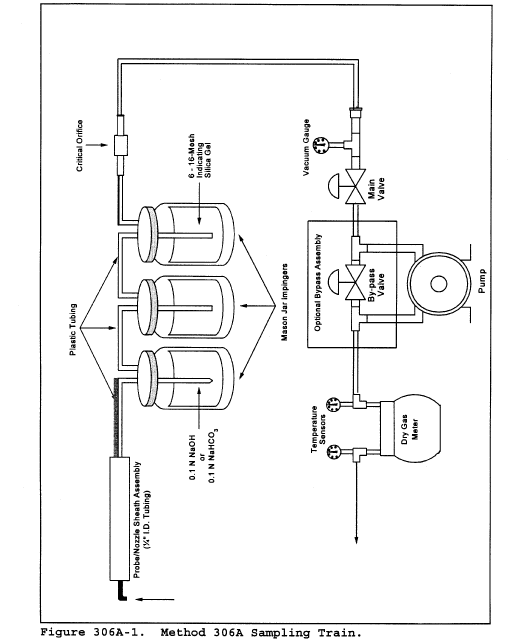
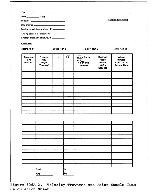
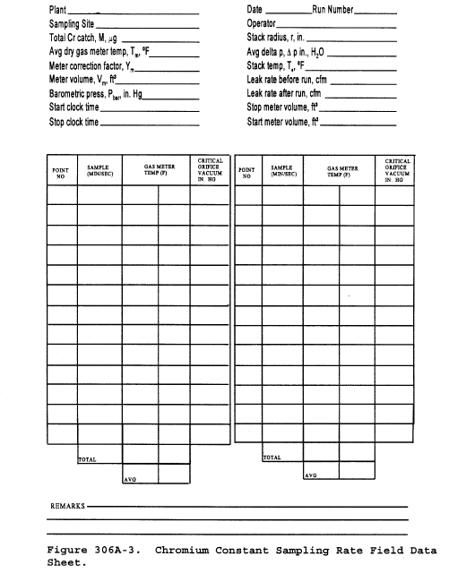 Method 306B -
Surface Tension Measurement for Tanks Used at Decorative Chromium
Electroplating and Chromium Anodizing Facilities Note:
Method 306B -
Surface Tension Measurement for Tanks Used at Decorative Chromium
Electroplating and Chromium Anodizing Facilities Note:
This method does not include all of the specifications (e.g., equipment and supplies) and procedures (e.g., sampling and analytical) essential to its performance. Some material is incorporated by reference from other methods in 40 CFR Part 60, Appendix A and in this part. Therefore, to obtain reliable results, persons using this method should have a thorough knowledge of at least Methods 5 and 306.
1.0 Scope and Application1.1 Analyte. Not applicable.
1.2 Applicability. This method is applicable to all chromium electroplating and chromium anodizing operations, and continuous chromium plating at iron and steel facilities where a wetting agent is used in the tank as the primary mechanism for reducing emissions from the surface of the plating solution.
2.0 Summary of Method2.1 During an electroplating or anodizing operation, gas bubbles generated during the process rise to the surface of the liquid and burst. Upon bursting, tiny droplets of chromic acid become entrained in ambient air. The addition of a wetting agent to the tank bath reduces the surface tension of the liquid and diminishes the formation of these droplets.
2.2 This method determines the surface tension of the bath using a stalagmometer or a tensiometer to confirm that there is sufficient wetting agent present.
3.0 Definitions [Reserved] 4.0 Interferences [Reserved] 5.0 Safety5.1 Disclaimer. This method may involve hazardous materials, operations, and equipment. This test method may not address all of the safety problems associated with its use. It is the responsibility of the user to establish appropriate safety and health practices and to determine the applicability of regulatory limitations prior to performing this test method.
6.0 Equipment and Supplies6.1 Stalagmometer. Any commercially available stalagmometer or equivalent surface tension measuring device may be used to measure the surface tension of the plating or anodizing tank liquid provided the procedures specified in Section 11.1.2 are followed.
6.2 Tensiometer. A tensiometer may be used to measure the surface tension of the tank liquid provided the procedures specified in ASTM Method D 1331-89, Standard Test Methods for Surface and Interfacial Tension of Solutions of Surface Active Agents (incorporated by reference - see § 63.14) are followed.
7.0 Reagents and Standards [Reserved] 8.0 Sample Collection, Sample Recovery, Sample Preservation, Sample Holding Times, Storage, and Transport [Reserved] 9.0 Quality Control [Reserved] 10.0 Calibration and Standardization [Reserved] 11.0 Analytical Procedure11.1 Procedure. The surface tension of the tank bath may be measured using a tensiometer, stalagmometer, or any other equivalent surface tension measuring device for measuring surface tension in dynes per centimeter.
11.1.1 If a tensiometer is used, the procedures specified in ASTM Method D 1331-89 must be followed.
11.1.2 If a stalagmometer is used, the procedures specified in Sections 11.1.2.1 through 11.1.2.3 must be followed.
11.1.2.1 Check the stalagmometer for visual signs of damage. If the stalagmometer appears to be chipped, cracked, or otherwise in disrepair, the instrument shall not be used.
11.1.2.2 Using distilled or deionized water and following the procedures provided by the manufacturer, count the number of drops corresponding to the distilled/deionized water liquid volume between the upper and lower etched marks on the stalagmometer. If the number of drops for the distilled/deionized water is not within ±1 drop of the number indicated on the instrument, the stalagmometer must be cleaned, using the procedures specified in Section 11.1.3 of this method, before using the instrument to measure the surface tension of the tank liquid.
11.1.2.2.1 If the stalagmometer must be cleaned, as indicated in Section 11.1.2.2, repeat the procedure specified in Section 11.1.2.2 before proceeding.
11.1.2.2.2 If, after cleaning and performing the procedure in Section 11.1.2.2, the number of drops indicated for the distilled/deionized water is not within ±1 drop of the number indicated on the instrument, either use the number of drops corresponding to the distilled/deionized water volume as the reference number of drops, or replace the instrument.
11.1.2.3 Determine the surface tension of the tank liquid using the procedures specified by the manufacturer of the stalagmometer.
11.1.3 Stalagmometer cleaning procedures. The procedures specified in Sections 11.1.3.1 through 11.1.3.10 shall be used for cleaning a stalagmometer, as required by Section 11.1.2.2.
11.1.3.1 Set up the stalagmometer on its stand in a fume hood.
11.1.3.2 Place a clean 150 (mL) beaker underneath the stalagmometer and fill the beaker with reagent grade concentrated nitric acid.
11.1.3.3 Immerse the bottom tip of the stalagmometer (approximately 1 centimeter (0.5 inches)) into the beaker.
11.1.3.4 Squeeze the rubber bulb and pinch at the arrow up (1) position to collapse.
11.1.3.5 Place the bulb end securely on top end of stalagmometer and carefully draw the nitric acid by pinching the arrow up (1) position until the level is above the top etched line.
11.1.3.6 Allow the nitric acid to remain in stalagmometer for 5 minutes, then carefully remove the bulb, allowing the acid to completely drain.
11.1.3.7 Fill a clean 150 mL beaker with distilled or deionized water.
11.1.3.8 Using the rubber bulb per the instructions in Sections 11.1.3.4 and 11.1.3.5, rinse and drain stalagmometer with deionized or distilled water.
11.1.3.9 Fill a clean 150 mL beaker with isopropyl alcohol.
11.1.3.10 Again using the rubber bulb per the instructions in Sections 11.1.3.4 and 11.1.3.5, rinse and drain stalagmometer twice with isopropyl alcohol and allow the stalagmometer to dry completely.
11.2 Frequency of Measurements.
11.2.1 Measurements of the bath surface tension are performed using a progressive system which decreases the frequency of surface tension measurements required when the proper surface tension is maintained.
11.2.1.1 Initially, following the compliance date, surface tension measurements must be conducted once every 4 hours of tank operation for the first 40 hours of tank operation.
11.2.1.2 Once there are no exceedances during a period of 40 hours of tank operation, measurements may be conducted once every 8 hours of tank operation.
11.2.1.3 Once there are no exceedances during a second period of 40 consecutive hours of tank operation, measurements may be conducted once every 40 hours of tank operation on an on-going basis, until an exceedance occurs. The maximum time interval for measurements is once every 40 hours of tank operation.
11.2.2 If a measurement of the surface tension of the solution is above the 40 dynes per centimeter limit when measured using a stalagmometer, above 33 dynes per centimeter when measured using a tensiometer, or above an alternate surface tension limit established during the performance test, the time interval shall revert back to the original monitoring schedule of once every 4 hours. A subsequent decrease in frequency would then be allowed according to Section 11.2.1.
12.0 Data Analysis and Calculations12.1 Log Book of Surface Tension Measurements and Fume Suppressant Additions.
12.1.1 The surface tension of the plating or anodizing tank bath must be measured as specified in Section 11.2.
12.1.2 The measurements must be recorded in the log book. In addition to the record of surface tension measurements, the frequency of fume suppressant maintenance additions and the amount of fume suppressant added during each maintenance addition must be recorded in the log book.
12.1.3 The log book will be readily available for inspection by regulatory personnel.
12.2 Instructions for Apparatus Used in Measuring Surface Tension.
12.2.1 Included with the log book must be a copy of the instructions for the apparatus used for measuring the surface tension of the plating or anodizing bath.
12.2.2 If a tensiometer is used, a copy of ASTM Method D 1331-89 must be included with the log book.
13.0 Method Performance [Reserved] 14.0 Pollution Prevention [Reserved] 15.0 Waste Management [Reserved] 16.0 References [Reserved] 17.0 Tables, Diagrams, Flowcharts, and Validation Data [Reserved] Method 307 - Determination of Emissions From Halogenated Solvent Vapor Cleaning Machines Using a Liquid Level Procedure 1. Applicability and Principle1.1 Applicability. This method is applicable to the determination of the halogenated solvent emissions from solvent vapor cleaners in the idling mode.
1.2 Principle. The solvent level in the solvent cleaning machine is measured using inclined liquid level indicators. The change in liquid level corresponds directly to the amount of solvent lost from the solvent cleaning machine.
2. Apparatus Note:Mention of trade names or specific products does not constitute endorsement by the Environmental Protection Agency.
2.1 Inclined Liquid Level Indicator. A schematic of the inclined liquid level indicators used in this method is shown in figure 307-1; two inclined liquid level indicators having 0.05 centimeters divisions or smaller shall be used. The liquid level indicators shall be made of glass, Teflon, or any similar material that will not react with the solvent being used. A 6-inch by 1-inch slope is recommended; however the slope may vary depending on the size and design of the solvent cleaning machine.
Note:It is important that the inclined liquid level indicators be constructed with ease of reading in mind. The inclined liquid level indicators should also be mounted so that they can be raised or lowered if necessary to suit the solvent cleaning machine size.
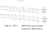
2.2 Horizontal Indicator. Device to check the inclined liquid level indicators orientation relative to horizontal.
2.3 Velocity Meter. Hotwire and vane anemometers, or other devices capable of measuring the flow rates ranging from 0 to 15.2 meters per minute across the solvent cleaning machine.
3. Procedure3.1 Connection of the Inclined Liquid Level Indicator. Connect one of the inclined liquid level indicators to the boiling sump drain and the other inclined liquid level indicator to the immersion sump drain using Teflon tubing and the appropriate fittings. A schematic diagram is shown in figure 307-2.
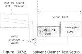
3.2 Positioning of Velocity Meter. Position the velocity meter so that it measures the flow rate of the air passing directly across the solvent cleaning machine.
3.3 Level the Inclined Liquid Level Indicators.
3.4 Initial Inclined Liquid Level Indicator Readings. Open the sump drainage valves. Allow the solvent cleaning machine to operate long enough for the vapor zone to form and the system to stabilize (check with manufacturer). Record the inclined liquid level indicators readings and the starting time on the data sheet. A sample data sheet is provided in figure 307-3.
Date Run Solvent type Solvent density, g/m 3 (lb/ft 3) Length of boiling sump (SB), m (ft) Width of boiling sump (WB), m (ft) Length of immersion sump (SI), m (ft) Width of immersion sump (WI), m (ft) Length of solvent vapor/air interface (SV), m (ft) ______ Width of solvent vapor/air interface (WV), m (ft) ______| Clock time | Boiling sump reading | Immersion sump reading | Flow rate reading |
|---|---|---|---|
3.5 Final Inclined Liquid Level Indicator Readings. At the end of the 16-hour test run, check to make sure the inclined liquid level indicators are level; if not, make the necessary adjustments. Record the final inclined liquid level indicators readings and time.
3.6 Determination of Solvent Vapor/Air Interface Area for Each Sump. Determine the area of the solvent/air interface of the individual sumps. Whenever possible, physically measure these dimensions, rather than using factory specifications. A schematic of the dimensions of a solvent cleaning machine is provided in figure 307-4.
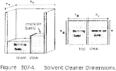 4.
Calculations
4.
Calculations
4.1 Nomenclature.
AB = area of boiling sump interface, m 2 (ft 2). AI = area of immersion sump interface, m 2 (ft 2). AV = area of solvent/air interface, m 2 (ft 2). E = emission rate, kg/m 2-hr (lb/ft 2-hr). K = 100,000 cm . g/m . kg for metric units. = 12 in./ft for English units. LBF = final boiling sump inclined liquid level indicators reading, cm (in.). LBi = initial boiling sump inclined liquid level indicators reading, cm (in.). LIf = final immersion sump inclined liquid level indicators reading, cm (in.). LIi = initial immersion sump inclined liquid level indicators reading, cm (in.). SB = length of the boiling sump, m (ft). SI = length of the immersion sump, m (ft). SV = length of the solvent vapor/air interface, m (ft). WB = width of the boiling sump, m (ft). WI = width of the immersion sump, m (ft). WV = width of the solvent vapor/air interface, m (ft). ρ = density of solvent, g/m3 (lb/ft3). θ = test time, hr.4.2 Area of Sump Interfaces. Calculate the areas of the boiling and immersion sump interfaces as follows:
AB = SB WB Eq. 307-1 AI = SI WI Eq. 307-24.3 Area of Solvent/Air Interface. Calculate the area of the solvent vapor/air interface as follows:
AV = SV WV Eq. 307-34.4 Emission Rate. Calculate the emission rate as follows:
Method 308 - Procedure for Determination of Methanol Emission From Stationary Sources 1.0 Scope and Application1.1 Analyte. Methanol. Chemical Abstract Service (CAS) No. 67-56-1.
1.2 Applicability. This method applies to the measurement of methanol emissions from specified stationary sources.
2.0 Summary of MethodA gas sample is extracted from the sampling point in the stack. The methanol is collected in deionized distilled water and adsorbed on silica gel. The sample is returned to the laboratory where the methanol in the water fraction is separated from other organic compounds with a gas chromatograph (GC) and is then measured by a flame ionization detector (FID). The fraction adsorbed on silica gel is extracted with deionized distilled water and is then separated and measured by GC/FID.
3.0 Definitions [Reserved] 4.0 Interferences [Reserved] 5.0 Safety5.1 Disclaimer. This method may involve hazardous materials, operations, and equipment. This test method does not purport to address all of the safety problems associated with its use. It is the responsibility of the user of this test method to establish appropriate safety and health practices and to determine the applicability of regulatory limitations before performing this test method.
5.2 Methanol Characteristics. Methanol is flammable and a dangerous fire and explosion risk. It is moderately toxic by ingestion and inhalation.
6.0 Equipment and Supplies6.1 Sample Collection. The following items are required for sample collection:
6.1.1 Sampling Train. The sampling train is shown in Figure 308-1 and component parts are discussed below.
6.1.1.1 Probe. Teflon ®, approximately 6-millimeter (mm) (0.24 inch) outside diameter.
6.1.1.2 Impinger. A 30-milliliter (ml) midget impinger. The impinger must be connected with leak-free glass connectors. Silicone grease may not be used to lubricate the connectors.
6.1.1.3 Adsorbent Tube. Glass tubes packed with the required amount of the specified adsorbent.
6.1.1.4 Valve. Needle valve, to regulate sample gas flow rate.
6.1.1.5 Pump. Leak-free diaphragm pump, or equivalent, to pull gas through the sampling train. Install a small surge tank between the pump and rate meter to eliminate the pulsation effect of the diaphragm pump on the rotameter.
6.1.1.6 Rate Meter. Rotameter, or equivalent, capable of measuring flow rate to within 2 percent of the selected flow rate of up to 1000 milliliter per minute (ml/min). Alternatively, the tester may use a critical orifice to set the flow rate.
6.1.1.7 Volume Meter. Dry gas meter (DGM), sufficiently accurate to measure the sample volume to within 2 percent, calibrated at the selected flow rate and conditions actually encountered during sampling, and equipped with a temperature sensor (dial thermometer, or equivalent) capable of measuring temperature accurately to within 3 °C (5.4 °F).
6.1.1.8 Barometer. Mercury (Hg), aneroid, or other barometer capable of measuring atmospheric pressure to within 2.5 mm (0.1 inch) Hg. See the NOTE in Method 5 (40 CFR part 60, appendix A), section 6.1.2.
6.1.1.9 Vacuum Gauge and Rotameter. At least 760-mm (30-inch) Hg gauge and 0- to 40-ml/min rotameter, to be used for leak-check of the sampling train.
6.2 Sample Recovery. The following items are required for sample recovery:
6.2.1 Wash Bottles. Polyethylene or glass, 500-ml, two.
6.2.2 Sample Vials. Glass, 40-ml, with Teflon ®-lined septa, to store impinger samples (one per sample).
6.2.3 Graduated Cylinder. 100-ml size.
6.3 Analysis. The following are required for analysis:
6.3.1 Gas Chromatograph. GC with an FID, programmable temperature control, and heated liquid injection port.
6.3.2 Pump. Capable of pumping 100 ml/min. For flushing sample loop.
6.3.3 Flow Meter. To monitor accurately sample loop flow rate of 100 ml/min.
6.3.4 Regulators. Two-stage regulators used on gas cylinders for GC and for cylinder standards.
6.3.5 Recorder. To record, integrate, and store chromatograms.
6.3.6 Syringes. 1.0- and 10-microliter (l) size, calibrated, for injecting samples.
6.3.7 Tubing Fittings. Stainless steel, to plumb GC and gas cylinders.
6.3.8 Vials. Two 5.0-ml glass vials with screw caps fitted with Teflon ®-lined septa for each sample.
6.3.9 Pipettes. Volumetric type, assorted sizes for preparing calibration standards.
6.3.10 Volumetric Flasks. Assorted sizes for preparing calibration standards.
6.3.11 Vials. Glass 40-ml with Teflon ®-lined septa, to store calibration standards (one per standard).
7.0 Reagents and Standards Note:Unless otherwise indicated, all reagents must conform to the specifications established by the Committee on Analytical Reagents of the American Chemical Society. Where such specifications are not available, use the best available grade.
7.1 Sampling. The following are required for sampling:
7.1.1 Water. Deionized distilled to conform to the American Society for Testing and Materials (ASTM) Specification D 1193-77, Type 3. At the option of the analyst, the potassium permanganate (KMnO4) test for oxidizable organic matter may be omitted when high concentrations of organic matter are not expected to be present.
7.1.2 Silica Gel. Deactivated chromatographic grade 20/40 mesh silica gel packed in glass adsorbent tubes. The silica gel is packed in two sections. The front section contains 520 milligrams (mg) of silica gel, and the back section contains 260 mg.
7.2 Analysis. The following are required for analysis:
7.2.1 Water. Same as specified in section 7.1.1.
7.2.2 [Reserved]
7.2.3 Methanol Stock Standard. Prepare a methanol stock standard by weighing 1 gram of methanol into a 100-ml volumetric flask. Dilute to 100 ml with water.
7.2.3.1 Methanol Working Standard. Prepare a methanol working standard by pipetting 1 ml of the methanol stock standard into a 100-ml volumetric flask. Dilute the solution to 100 ml with water.
7.2.3.2 Methanol Standards For Impinger Samples. Prepare a series of methanol standards by pipetting 1, 2, 5, 10, and 25 ml of methanol working standard solution respectively into five 50-ml volumetric flasks. Dilute the solutions to 50 ml with water. These standards will have 2, 4, 10, 20, and 50 µg/ml of methanol, respectively. After preparation, transfer the solutions to 40-ml glass vials capped with Teflon ® septa and store the vials under refrigeration. Discard any excess solution.
7.2.3.3 Methanol Standards for Adsorbent Tube Samples. Prepare a series of methanol standards by first pipetting 10 ml of the methanol working standard into a 100-ml volumetric flask and diluting the contents to exactly 100 ml with deionized distilled water. This standard will contain 10 µg/ml of methanol. Pipette 5, 15, and 25 ml of this standard, respectively, into three 50-ml volumetric flasks. Dilute each solution to 50 ml with deionized distilled water. These standards will have 1, 3, and 5 µg/ml of methanol, respectively. Transfer all four standards into 40-ml glass vials capped with Teflon®-lined septa and store under refrigeration. Discard any excess solution.
7.2.4 GC Column. Capillary column, 30 meters (100 feet) long with an inside diameter (ID) of 0.53 mm (0.02 inch), coated with DB 624 to a film thickness of 3.0 micrometers, (µm) or an equivalent column. Alternatively, a 30-meter capillary column coated with polyethylene glycol to a film thickness of 1 µm such as AT-WAX or its equivalent.
7.2.5 Helium. Ultra high purity.
7.2.6 Hydrogen. Zero grade.
7.2.7 Oxygen. Zero grade.
8.0 Procedure8.1 Sampling. The following items are required for sampling:
8.1.1 Preparation of Collection Train. Measure 20 ml of water into the midget impinger. The adsorbent tube must contain 520 mg of silica gel in the front section and 260 mg of silica gel in the backup section. Assemble the train as shown in Figure 308-1. An optional, second impinger that is left empty may be placed in front of the water-containing impinger to act as a condensate trap. Place crushed ice and water around the impinger.
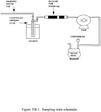
8.1.2 Leak Check. A leak check before and after the sampling run is mandatory. The leak-check procedure is as follows:
Temporarily attach a suitable (e.g., 0- to 40-ml/min) rotameter to the outlet of the DGM, and place a vacuum gauge at or near the probe inlet. Plug the probe inlet, pull a vacuum of at least 250 mm (10 inch) Hg or the highest vacuum experienced during the sampling run, and note the flow rate as indicated by the rotameter. A leakage rate in excess of 2 percent of the average sampling rate is acceptable.
Note:Carefully release the probe inlet plug before turning off the pump.
8.1.3 Sample Collection. Record the initial DGM reading and barometric pressure. To begin sampling, position the tip of the Teflon ® tubing at the sampling point, connect the tubing to the impinger, and start the pump. Adjust the sample flow to a constant rate between 200 and 1000 ml/min as indicated by the rotameter. Maintain this constant rate (±10 percent) during the entire sampling run. Take readings (DGM, temperatures at DGM and at impinger outlet, and rate meter) at least every 5 minutes. Add more ice during the run to keep the temperature of the gases leaving the last impinger at 20 °C (68 °F) or less. At the conclusion of each run, turn off the pump, remove the Teflon ® tubing from the stack, and record the final readings. Conduct a leak check as in section 8.1.2. (This leak check is mandatory.) If a leak is found, void the test run or use procedures acceptable to the Administrator to adjust the sample volume for the leakage.
8.2 Sample Recovery. The following items are required for sample recovery:
8.2.1 Impinger. Disconnect the impinger. Pour the contents of the midget impinger into a graduated cylinder. Rinse the midget impinger and the connecting tubes with water, and add the rinses to the graduated cylinder. Record the sample volume. Transfer the sample to a glass vial and cap with a Teflon ® septum. Discard any excess sample. Place the samples in an ice chest for shipment to the laboratory.
8.2.2. Adsorbent Tubes. Seal the silica gel adsorbent tubes and place them in an ice chest for shipment to the laboratory.
9.0 Quality Control9.1 Miscellaneous Quality Control Measures. The following quality control measures are required:
| Section | Quality control measure | Effect |
|---|---|---|
| 8.1.2, 8.1.3, 10.1 | Sampling equipment leak check and calibration | Ensures accurate measurement of sample volume. |
| 10.2 | GC calibration | Ensures precision of GC analysis. |
| 13.0 | Methanol spike recovery check | Verifies all methanol in stack gas is being captured in impinge/adsorbent tube setup. |
10.1 Metering System. The following items are required for the metering system:
10.1.1 Initial Calibration.
10.1.1.1 Before its initial use in the field, first leak-check the metering system (drying tube, needle valve, pump, rotameter, and DGM) as follows: Place a vacuum gauge at the inlet to the drying tube, and pull a vacuum of 250 mm (10 inch) Hg; plug or pinch off the outlet of the flow meter, and then turn off the pump. The vacuum shall remain stable for at least 30 seconds. Carefully release the vacuum gauge before releasing the flow meter end.
10.1.1.2 Next, remove the drying tube, and calibrate the metering system (at the sampling flow rate specified by the method) as follows: Connect an appropriately sized wet test meter (e.g., 1 liter per revolution (0.035 cubic feet per revolution)) to the inlet of the drying tube. Make three independent calibrations runs, using at least five revolutions of the DGM per run. Calculate the calibration factor, Y (wet test meter calibration volume divided by the DGM volume, both volumes adjusted to the same reference temperature and pressure), for each run, and average the results. If any Y-value deviates by more than 2 percent from the average, the metering system is unacceptable for use. Otherwise, use the average as the calibration factor for subsequent test runs.
10.1.2 Posttest Calibration Check. After each field test series, conduct a calibration check as in section 10.1.1 above, except for the following variations: (a) The leak check is not to be conducted, (b) three, or more revolutions of the DGM may be used, and (c) only two independent runs need be made. If the calibration factor does not deviate by more than 5 percent from the initial calibration factor (determined in section 10.1.1), then the DGM volumes obtained during the test series are acceptable. If the calibration factor deviates by more than 5 percent, recalibrate the metering system as in section 10.1.1, and for the calculations, use the calibration factor (initial or recalibration) that yields the lower gas volume for each test run.
10.1.3 Temperature Sensors. Calibrate against mercury-in-glass thermometers. An alternative mercury-free thermometer may be used if the thermometer is, at a minimum, equivalent in terms of performance or suitably effective for the specific temperature measurement application.
10.1.4 Rotameter. The rotameter need not be calibrated, but should be cleaned and maintained according to the manufacturer's instruction.
10.1.5 Barometer. Calibrate against a mercury barometer.
10.2 Gas Chromatograph. The following procedures are required for the gas chromatograph:
10.2.1 Initial Calibration. Inject 1 µl of each of the standards prepared in sections 7.2.3.3 and 7.2.3.4 into the GC and record the response. Repeat the injections for each standard until two successive injections agree within 5 percent. Using the mean response for each calibration standard, prepare a linear least squares equation relating the response to the mass of methanol in the sample. Perform the calibration before analyzing each set of samples.
10.2.2 Continuing Calibration. At the beginning of each day, analyze the mid level calibration standard as described in section 10.5.1. The response from the daily analysis must agree with the response from the initial calibration within 10 percent. If it does not, the initial calibration must be repeated.
11.0 Analytical Procedure11.1 Gas Chromatograph Operating Conditions. The following operating conditions are required for the GC:
11.1.1 Injector. Configured for capillary column, splitless, 200 °C (392 °F).
11.1.2 Carrier. Helium at 10 ml/min.
11.1.3 Oven. Initially at 45 °C for 3 minutes; then raise by 10 °C to 70 °C; then raise by 70 °C/min to 200 °C.
11.2 Impinger Sample. Inject 1 µl of the stored sample into the GC. Repeat the injection and average the results. If the sample response is above that of the highest calibration standard, either dilute the sample until it is in the measurement range of the calibration line or prepare additional calibration standards. If the sample response is below that of the lowest calibration standard, prepare additional calibration standards. If additional calibration standards are prepared, there shall be at least two that bracket the response of the sample. These standards should produce approximately 50 percent and 150 percent of the response of the sample.
11.3 Silica Gel Adsorbent Sample. The following items are required for the silica gel adsorbent samples:
11.3.1 Preparation of Samples. Extract the front and backup sections of the adsorbent tube separately. With a file, score the glass adsorbent tube in front of the first section of silica gel. Break the tube open. Remove and discard the glass wool. Transfer the first section of the silica gel to a 5-ml glass vial and stopper the vial. Remove the spacer between the first and second section of the adsorbent tube and discard it. Transfer the second section of silica gel to a separate 5-ml glass vial and stopper the vial.
11.3.2 Desorption of Samples. Add 3 ml of deionized distilled water to each of the stoppered vials and shake or vibrate the vials for 30 minutes.
11.3.3 Inject a 1-µl aliquot of the diluted sample from each vial into the GC. Repeat the injection and average the results. If the sample response is above that of the highest calibration standard, either dilute the sample until it is in the measurement range of the calibration line or prepare additional calibration standards. If the sample response is below that of the lowest calibration standard, prepare additional calibration standards. If additional calibration standards are prepared, there shall be at least two that bracket the response of the sample. These standards should produce approximately 50 percent and 150 percent of the response of the sample.
12.0 Data Analysis and Calculations12.1 Nomenclature.
Caf = Concentration of methanol in the front of the adsorbent tube, µg/ml. Cab = Concentration of methanol in the back of the adsorbent tube, µg/ml. Ci = Concentration of methanol in the impinger portion of the sample train,µg/ml. E = Mass emission rate of methanol, µg/hr (lb/hr). ms = Total mass of compound measured in impinger and on adsorbent with spiked train (mg). mu = Total mass of compound measured in impinger and on adsorbent with unspiked train (mg). mv = Mass per volume of spiked compound measured (mg/L). Mtot = Total mass of methanol collected in the sample train, µg. Pbar = Barometric pressure at the exit orifice of the DGM, mm Hg (in. Hg). Pstd = Standard absolute pressure, 760 mm Hg (29.92 in. Hg). Qstd = Dry volumetric stack gas flow rate corrected to standard conditions, dscm/hr (dscf/hr). R = fraction of spiked compound recovered s = theoretical concentration (ppm) of spiked target compound Tm = Average DGM absolute temperature, degrees K (°R). Tstd = Standard absolute temperature, 293 degrees K (528 °R). Vaf = Volume of front half adsorbent sample, ml. Vab = Volume of back half adsorbent sample, ml. Vi = Volume of impinger sample, ml. Vm = Dry gas volume as measured by the DGM, dry cubic meters (dcm), dry cubic feet (dcf). Vm(std) = Dry gas volume measured by the DGM, corrected to standard conditions, dry standard cubic meters (dscm), dry standard cubic feet (dscf).12.2 Mass of Methanol. Calculate the total mass of methanol collected in the sampling train using Equation 308-1.

12.3 Dry Sample Gas Volume, Corrected to Standard Conditions. Calculate the volume of gas sampled at standard conditions using Equation 308-2.
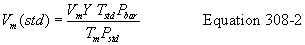
12.4 Mass Emission Rate of Methanol. Calculate the mass emission rate of methanol using Equation 308-3.

12.5 Recovery Fraction (R)

 13.0 Method
Performance
13.0 Method
Performance
Since a potential sample may contain a variety of compounds from various sources, a specific precision limit for the analysis of field samples is impractical. Precision in the range of 5 to 10 percent relative standard deviation (RSD) is typical for gas chromatographic techniques, but an experienced GC operator with a reliable instrument can readily achieve 5 percent RSD. For this method, the following combined GC/operator values are required.
(a) Precision. Calibration standards must meet the requirements in section 10.2.1 or 10.2.2 as applicable.
(b) Recovery. After developing an appropriate sampling and analytical system for the pollutants of interest, conduct the following spike recovery procedure at each sampling point where the method is being applied.
i. Methanol Spike. Set up two identical sampling trains. Collocate the two sampling probes in the stack. The probes shall be placed in the same horizontal plane, where the first probe tip is 2.5 cm from the outside edge of the other. One of the sampling trains shall be designated the spiked train and the other the unspiked train. Spike methanol into the impinger, and onto the adsorbent tube in the spiked train prior to sampling. The total mass of methanol shall be 40 to 60 percent of the mass expected to be collected with the unspiked train. Sample the stack gas into the two trains simultaneously. Analyze the impingers and adsorbents from the two trains utilizing identical analytical procedures and instrumentation. Determine the fraction of spiked methanol recovered (R) by combining the amount recovered in the impinger and in the adsorbent tube, using the equations in section 12.5. Recovery values must fall in the range: 0.70 ≤ R ≤ 1.30. Report the R value in the test report.
ii. [Reserved]
14.0 Pollution Prevention [Reserved] 15.0 Waste Management [Reserved] 16.0 Bibliography1. Rom, J.J. “Maintenance, Calibration, and Operation of Isokinetic Source Sampling Equipment.” Office of Air Programs, Environmental Protection Agency. Research Triangle Park, NC. APTD-0576 March 1972.
2. Annual Book of ASTM Standards. Part 31; Water, Atmospheric Analysis. American Society for Testing and Materials. Philadelphia, PA. 1974. pp. 40-42.
3. Westlin, P.R. and R.T. Shigehara. “Procedure for Calibrating and Using Dry Gas Volume Meters as Calibration Standards.” Source Evaluation Society Newsletter. 3 (1) :17-30. February 1978.
4. Yu, K.K. “Evaluation of Moisture Effect on Dry Gas Meter Calibration.” Source Evaluation Society Newsletter. 5 (1) :24-28. February 1980.
5. NIOSH Manual of Analytical Methods, Volume 2. U.S. Department of Health and Human Services National Institute for Occupational Safety and Health. Center for Disease Control. 4676 Columbia Parkway, Cincinnati, OH 45226. (available from the Superintendent of Documents, Government Printing Office, Washington, DC 20402.)
6. Pinkerton, J.E. “Method for Measuring Methanol in Pulp Mill Vent Gases.” National Council of the Pulp and Paper Industry for Air and Stream Improvement, Inc., New York, NY.
17.0 Tables, Diagrams, Flowcharts, and Validation Data [Reserved] Method 310A - Determination of Residual Hexane Through Gas Chromatography 1.0 Scope and Application1.1 This method is used to analyze any crumb rubber or water samples for residual hexane content.
1.2 The sample is heated in a sealed bottle with an internal standard and the vapor is analyzed by gas chromatography.
2.0 Summary of Method2.1 This method, utilizing a capillary column gas chromatograph with a flame ionization detector, determines the concentration of residual hexane in rubber crumb samples.
3.0 Definitions3.1 The definitions are included in the text as needed.
4.0 Interferences4.1 There are no known interferences.
5.0 Safety5.1 It is the responsibility of the user of this procedure to establish safety and health practices applicable to their specific operation.
6.0 Equipment and Supplies6.1 Gas Chromatograph with a flame ionization detector and data handling station equipped with a capillary column 30 meters long.
6.2 Chromatograph conditions for Sigma 1:
6.2.1 Helium pressure: 50# inlet A, 14# aux
6.2.2 Carrier flow: 25 cc/min
6.2.3 Range switch: 100x
6.2.4 DB: 1 capillary column
6.3 Chromatograph conditions for Hewlett-Packard GC:
6.3.1 Initial temperature: 40 °C
6.3.2 Initial time: 8 min
6.3.3 Rate: 0
6.3.4 Range: 2
6.3.5 DB: 1705 capillary column
6.4 Septum bottles and stoppers
6.5 Gas Syringe - 0.5 cc
7.0 Reagents and Standards7.1 Chloroform, 99.9 + %, A.S.C. HPLC grade
8.0 Sample Collection, Preservation, and Storage8.1 A representative sample should be caught in a clean 8 oz. container with a secure lid.
8.2 The container should be labeled with sample identification, date and time.
9.0 Quality Control9.1 The instrument is calibrated by injecting calibration solution (Section 10.2 of this method) five times.
9.2 The retention time for components of interest and relative response of monomer to the internal standard is determined.
9.3 Recovery efficiency must be determined once for each sample type and whenever modifications are made to the method.
9.3.1 Determine the percent hexane in three separate dried rubber crumb samples.
9.3.2 Weigh a portion of each crumb sample into separate sample bottles and add a known amount of hexane (10 microliters) by microliter syringe and 20 microliters of internal standard. Analyze each by the described procedure and calculate the percent recovery of the known added hexane.
9.3.3 Repeat the previous step using twice the hexane level (20 microliters), analyze and calculate the percent recovery of the known added hexane.
9.3.4 Set up two additional sets of samples using 10 microliters and 20 microliters of hexane as before, but add an amount of water equal to the dry crumb used. Analyze and calculate percent recovery to show the effect of free water on the results obtained.
9.3.5 A value of R between 0.70 and 1.30 is acceptable.
9.3.6 R shall be used to correct all reported results for each compound by dividing the measured results of each compound by the R for that compound for the same sample type.
10.0 Calibration and Instrument Settings10.1 Calibrate the chromatograph using a standard made by injecting 10 µl of fresh hexane and 20 µl of chloroform into a sealed septum bottle. This standard will be 0.6 wt.% total hexane based on 1 gram of dry rubber.
10.2 Analyze the hexane used and calculate the percentage of each hexane isomer (2-methylpentane, 3-methylpentane, n-hexane, and methylcyclo-pentane). Enter these percentages into the method calibration table.
10.3 Heat the standard bottle for 30 minutes in a 105 °C oven.
10.4 Inject about 0.25 cc of vapor into the gas chromatograph and after the analysis is finished, calibrate according to the procedures described by the instrument manufacturer.
11.0 Procedure11.1 Using a cold mill set at a wide roller gap (125-150 mm), mill about 250 grams of crumb two times to homogenize the sample.
11.2 Weigh about 2 grams of wet crumb into a septum bottle and cap with a septum ring. Add 20 µl of chloroform with a syringe and place in a 105 °C oven for 45 minutes.
11.3 Run the moisture content on a separate portion of the sample and calculate the grams of dry rubber put into the septum bottle.
11.4 Set up the data station on the required method and enter the dry rubber weight in the sample weight field.
11.5 Inject a 0.25 cc vapor sample into the chromatograph and push the start button.
11.6 At the end of the analysis, the data station will print a report listing the concentration of each identified component.
11.7 To analyze water samples, pipet 5 ml of sample into the septum bottle, cap and add 20 µl of chloroform. Place in a 105 °C oven for 30 minutes.
11.8 Enter 5 grams into the sample weight field.
11.9 Inject a 0.25 cc vapor sample into the chromatograph and push the start button.
11.10 At the end of the analysis, the data station will print a report listing the concentration of each identified component.
12.0 Data Analysis and Calculation12.1 For samples that are prepared as in section 11 of this method, ppm n-hexane is read directly from the computer.
12.2 The formulas for calculation of the results are as follows:
ppmhexane = (Ahexane × Rhexane)/(Ais × Ris) Where: Ahexane = area of hexane Rhexane = response of hexane Ais = area of the internal standard Ris = response of the internal standard % hexane in crumb = (ppmhexane/sample amount)10012.3 Correct the results by the value of R (as determined in sections 9.3.4, 9.3.5, and 9.3.6 of this method).
13.0 Method Performance13.1 The test has a standard deviation of 0.14 wt% at 0.66 wt% hexane. Spike recovery of 12 samples at two levels of hexane averaged 102.3%. Note: Recovery must be determined for each type of sample. The values given here are meant to be examples of method performance.
14.0 Pollution Prevention14.1 Waste generation should be minimized where possible. Sample size should be an amount necessary to adequately run the analysis.
15.0 Waste Management15.1 All waste shall be handled in accordance with federal and state environmental regulations.
16.0 References and Publications16.1 DSM Copolymer Test Method T-3380.
Method 310B - Determination of Residual Hexane Through Gas Chromatography 1.0 Scope and Application| Analyte | CAS No. | Matrix | Method sensitivity (5.5g sample size) |
|---|---|---|---|
| Hexane | 110-54-3 | Rubber crumb | .01 wt%. |
| Applicable Termonomer | Rubber crumb | .001 wt%. |
1.1 Data Quality Objectives:
In the production of ethylene-propylene terpolymer crumb rubber, the polymer is recovered from solution by flashing off the solvent with steam and hot water. The resulting water-crumb slurry is then pumped to the finishing units. Certain amounts of solvent (hexane being the most commonly used solvent) and diene monomer remain in the crumb. The analyst uses the following procedure to determine those amounts.
2.0 Summary of Method2.1 The crumb rubber sample is dissolved in toluene to which heptane has been added as an internal standard. Acetone is then added to this solution to precipitate the crumb, and the supernatant is analyzed for hexane and diene by a gas chromatograph equipped with a flame ionization detector (FID).
3.0 Definitions3.1 Included in text as needed.
4.0 Interferences4.1 None known.
4.2 Benzene, introduced as a contaminant in the toluene solvent, elutes between methyl cyclopentane and cyclohexane. However, the benzene peak is completely resolved.
4.3 2,2-dimethyl pentane, a minor component of the hexane used in our process, elutes just prior to methyl cyclopentane. It is included as “hexane” in the analysis whether it is integrated separately or included in the methyl cyclopentane peak.
5.0 Safety5.1 This procedure does not purport to address all of the safety concerns associated with its use. It is the responsibility of the user of this procedure to establish appropriate safety and health practices and determine the applicability of regulatory limitations prior to use.
5.2 Chemicals used in this analysis are flammable and hazardous (see specific toxicity information below). Avoid contact with sources of ignition during sample prep. All handling should be done beneath a hood. Playtex or nitrile gloves recommended.
5.3 Hexane is toxic by ingestion and inhalation. Vapor inhalation causes irritation of nasal and respiratory passages, headache, dizziness, nausea, central nervous system depression. Chronic overexposure can cause severe nerve damage. May cause irritation on contact with skin or eyes. May cause damage to kidneys.
5.4 Termonomer may be harmful by inhalation, ingestion, or skin absorption. Vapor or mist is irritating to the eyes, mucous membranes, and upper respiratory tract. Causes skin irritation.
5.5 Toluene is harmful or fatal if swallowed. Vapor harmful if inhaled. Symptoms: headache, dizziness, hallucinations, distorted perceptions, changes in motor activity, nausea, diarrhea, respiratory irritation, central nervous system depression, unconsciousness, liver, kidney and lung damage. Contact can cause severe eye irritation. May cause skin irritation. Causes irritation of eyes, nose, and throat.
5.6 Acetone, at high concentrations or prolonged overexposure, may cause headache, dizziness, irritation of eyes and respiratory tract, loss of strength, and narcosis. Eye contact causes severe irritation; skin contact may cause mild irritation. Concentrations of 20,000 ppm are immediately dangerous to life and health.
5.7 Heptane is harmful if inhaled or swallowed. May be harmful if absorbed through the skin. Vapor or mist is irritating to the eyes, mucous membranes, and upper respiratory tract. Prolonged or repeated exposure to skin causes defatting and dermatitis.
5.8 The steam oven used to dry the polymer in this procedure is set at 110 °C. Wear leather gloves when removing bottles from the oven.
6.0 Equipment and Supplies6.1 4000-ml volumetric flask
6.2 100-ml volumetric pipette
6.3 1000-ml volumetric flask
6.4 8-oz. French Square sample bottles with plastic-lined caps
6.5 Top-loading balance
6.6 Laboratory shaker
6.7 Laboratory oven set at 110 °C (steam oven)
6.8 Gas chromatograph, Hewlett-Packard 5890A, or equivalent, interfaced with HP 7673A (or equivalent) autosampler (equipped with nanoliter adapter and robotic arm), and HP 3396 series II or 3392A (or equivalent) integrator/controller.
6.9 GC column, capillary type, 50m × 0.53mm, methyl silicone, 5 micron film thickness, Quadrex, or equivalent.
6.10 Computerized data acquisition system, such as CIS/CALS
6.11 Crimp-top sample vials and HP p/n 5181-1211 crimp caps, or screw-top autosampler vials and screw tops.
6.12 Glass syringes, 5-ml, with “Luer-lock” fitting
6.13 Filters, PTFE, .45 µm pore size, Gelman Acrodisc or equivalent, to fit on Luer-lock syringes (in 6.12, above).
7.0 Reagents and Standards7.1 Reagent toluene, EM Science Omnisolv (or equivalent)
Purity Check: Prior to using any bottle of reagent toluene, analyze it according to section 11.2 of this method. Use the bottle only if hexane, heptane, and termonomer peak areas are less than 15 each (note that an area of 15 is equivalent to less than 0.01 wt% in a 10g sample).
7.2 Reagent acetone, EM Science Omnisolv HR-GC (or equivalent)
Purity Check: Prior to using any bottle of reagent acetone, analyze it according to section 11.2 of this method. Use the bottle only if hexane, heptane, and termonomer peak areas are less than 15 each.
7.3 Reagent heptane, Aldrich Chemical Gold Label, Cat #15,487-3 (or equivalent)
Purity Check: Prior to using any bottle of reagent heptane, analyze it according to section 11.2 of this method. Use the bottle only if hexane and termonomer peak areas are less than 5 each.
7.4 Internal standard solution - used as a concentrate for preparation of the more dilute Polymer Dissolving Solution. It contains 12.00g heptane/100ml of solution which is 120.0g per liter.
Preparation of internal standard solution (polymer dissolving stock solution):
| Action | Notes |
|---|---|
| 7.4.1 Tare a clean, dry 1-liter volumetric flask on the balance. Record the weight to three places | If the 1-liter volumetric flask is too tall to fit in the balance case, you can shield the flask from drafts by inverting a paint bucket with a hole cut in the bottom over the balance cover. Allow the neck of the flask to project through the hole in the bucket. |
| 7.4.2 Weigh 120.00 g of n-heptane into the flask. Record the total weight of the flask and heptane as well as the weight of heptane added | Use 99 + % n-heptane from Aldrich or Janssen Chimica. |
| 7.4.3 Fill the flask close to the mark with toluene, about 1 to 2″ below the mark | Use EM Science Omnisolve toluene, Grade TX0737-1, or equivalent. |
| 7.4.4 Shake the flask vigorously to mix the contents | Allow any bubbles to clear before proceeding to the next step. |
| 7.4.5 Top off the flask to the mark with toluene. Shake vigorously, as in section 7.4.4 of this method, to mix well | |
| 7.4.6 Weigh the flask containing the solution on the three place balance record the weight | |
| 7.4.7 Transfer the contents of the flask to a 1 qt Boston round bottle | Discard any excess solution |
| 7.4.8 Label the bottle with the identity of the contents, the weights of heptane and toluene used, the date of preparation and the preparer's name | Be sure to include the words “Hexane in Crumb Polymer Dissolving Stock Solution” on the label. |
| 7.4.9 Refrigerate the completed blend for the use of the routine Technicians |
7.5 Polymer Dissolving Solution (“PDS”) - Heptane (as internal standard) in toluene. This solution contains 0.3g of heptane internal standard per 100 ml of solution.
7.5.1 Preparation of Polymer Dissolving Solution. Fill a 4,000-ml volumetric flask about 3/4 full with toluene.
7.5.2 Add 100 ml of the internal standard solution (section 7.4 of this method) to the flask using the 100ml pipette.
7.5.3 Fill the flask to the mark with toluene. Discard any excess.
7.5.4 Add a large magnetic stirring bar to the flask and mix by stirring.
7.5.5 Transfer the polymer solvent solution to the one-gallon labeled container with 50ml volumetric dispenser attached.
7.5.6 Purity Check: Analyze according to section 11.2. NOTE: You must “precipitate” the sample with an equal part of acetone (thus duplicating actual test conditions - see section 11.1 of this method, sample prep) before analyzing. Analyze the reagent 3 times to quantify the C6 and termonomer interferences. Inspect the results to ensure good agreement among the three runs (within 10%).
7.5.7 Tag the bottle with the following information:
POLYMER DISSOLVING SOLUTION FOR C6 IN CRUMB ANALYSIS PREPARER'S NAME DATE CALS FILE ID'S OF THE THREE ANALYSES FOR PURITY (from section 7.5.6 of this method)7.6 Quality Control Solution: the quality control solution is prepared by adding specific amounts of mixed hexanes (barge hexane), n-nonane and termonomer to some polymer dissolving solution. Nonane elutes in the same approximate time region as termonomer and is used to quantify in that region because it has a longer shelf life. Termonomer, having a high tendency to polymerize, is used in the QC solution only to ensure that both termonomer isomers elute at the proper time.
First, a concentrated stock solution is prepared; the final QC solution can then be prepared by diluting the stock solution.
7.6.1 In preparation of stock solution, fill a 1-liter volumetric flask partially with polymer dissolving solution (PDS) - see section 7.5 of this method. Add 20.0 ml barge hexane, 5.0 ml n-nonane, and 3 ml termonomer. Finish filling the volumetric to the mark with PDS.
7.6.2 In preparation of quality control solution, dilute the quality control stock solution (above) precisely 1:10 with PDS, i.e. 10 ml of stock solution made up to 100 ml (volumetric flask) with PDS. Pour the solution into a 4 oz. Boston round bottle and store in the refrigerator.
8.0 Sample Collection, Preservation and Storage8.1 Line up facility to catch crumb samples. The facility is a special facility where the sample is drawn.
8.1.1 Ensure that the cock valve beneath facility is closed.
8.1.2 Line up the system from the slurry line cock valve to the cock valve at the nozzle on the stripper.
8.1.3 Allow the system to flush through facility for a period of 30 seconds.
8.2 Catch a slurry crumb sample.
8.2.1 Simultaneously close the cock valves upstream and downstream of facility.
8.2.2 Close the cock valve beneath the slurry line in service.
8.2.3 Line up the cooling tower water through the sample bomb water jacket to the sewer for a minimum of 30 minutes.
8.2.4 Place the sample catching basket beneath facility and open the cock valve underneath the bomb to retrieve the rubber crumb.
8.2.5 If no rubber falls by gravity into the basket, line up nitrogen to the bleeder upstream of the sample bomb and force the rubber into the basket.
8.2.6 Close the cock valve underneath the sample bomb.
8.3 Fill a plastic “Whirl-pak” sample bag with slurry crumb and send it to the lab immediately.
8.4 Once the sample reaches the lab, it should be prepped as soon as possible to avoid hexane loss through evaporation. Samples which have lain untouched for more than 30 minutes should be discarded.
9.0 Quality ControlQuality control is monitored via a computer program that tracks analyses of a prepared QC sample (from section 7.6.2 of this method). The QC sample result is entered daily into the program, which plots the result as a data point on a statistical chart. If the data point does not satisfy the “in-control” criteria (as defined by the lab quality facilitator), an “out-of-control” flag appears, mandating corrective action.
In addition, the area of the n-heptane peak is monitored so that any errors in making up the polymer dissolving solution will be caught and corrected. Refer to section 12.4 of this method.
9.1 Fill an autosampler vial with the quality control solution (from section 7.6.2 of this method) and analyze on the GC as normal (per section 11 of this method).
9.2 Add the concentrations of the 5 hexane isomers as they appear on the CALS printout. Also include the 2,2-dimethyl-pentane peak just ahead of the methyl cyclopentane (the fourth major isomer) peak in the event that the peak integration split this peak out. Do not include the benzene peak in the sum. Note the nonane concentration. Record both results (total hexane and nonane) in the QC computer program. If out of control, and GC appears to be functioning within normal parameters, reanalyze a fresh control sample. If the fresh QC is not in control, check stock solution for contaminants or make up a new QC sample with the toluene currently in use. If instrument remains out-of-control, more thorough GC troubleshooting may be needed.
Also, verify that the instrument has detected both isomers of termonomer (quantification not necessary - see section 7.0 of this method).
9.3 Recovery efficiency must be determined for high ethylene concentration, low ethylene concentration, E-P terpolymer, or oil extended samples and whenever modifications are made to the method. Recovery shall be between 70 and 130 percent. All test results must be corrected by the recovery efficiency value (R).
9.3.1 Approximately 10 grams of wet EPDM crumb (equivalent to about 5 grams of dry rubber) shall be added to six sample bottles containing 100 ml of hexane in crumb polymer dissolving solution (toluene containing 0.3 gram n-heptane/100 ml solution). The polymer shall be dissolved by agitating the bottles on a shaker for 4 hours. The polymer shall be precipitated using 100 ml acetone.
9.3.2 The supernatant liquid shall be decanted from the polymer. Care shall be taken to remove as much of the liquid phase from the sample as possible to minimize the effect of retained liquid phase upon the next cycle of the analysis. The supernatant liquid shall be analyzed by gas chromatography using an internal standard quantitation method with heptane as the internal standard.
9.3.3 The precipitated polymer from the steps described above shall be redissolved using toluene as the solvent. No heptane shall be added to the sample in the second dissolving step. The toluene solvent and acetone precipitant shall be determined to be free of interfering compounds.
9.3.4 The rubber which was dissolved in the toluene shall be precipitated with acetone as before, and the supernatant liquid decanted from the precipitated polymer. The liquid shall be analyzed by gas chromatography and the rubber phase dried in a steam-oven to determine the final polymer weight.
9.3.5 The ratios of the areas of the hexane peaks and of the heptane internal standard peak shall be calculated for each of the six samples in the two analysis cycles outlined above. The area ratios of the total hexane to heptane (R1) shall be determined for the two analysis cycles of the sample set. The ratio of the values of R1 from the second analysis cycle to the first cycle shall be determined to give a second ratio (R2).
10.0 Calibration and StandardizationThe procedure for preparing a Quality Control sample with the internal standard in it is outlined in section 7.6 of this method.
10.1 The relative FID response factors for n-heptane, the internal standard, versus the various hexane isomers and termonomer are relatively constant and should seldom need to be altered. However Baseline construction is a most critical factor in the production of good data. For this reason, close attention should be paid to peak integration. Procedures for handling peak integration will depend upon the data system used.
10.2 If recalibration of the analysis is needed, make up a calibration blend of the internal standard and the analytes as detailed below and analyze it using the analytical method used for the samples.
10.2.1 Weigh 5 g heptane into a tared scintillation vial to five places.
10.2.2 Add 0.2 ml termonomer to the vial and reweigh.
10.2.3 Add 0.5 ml hexane to the vial and reweigh.
10.2.4 Cap, and shake vigorously to mix.
10.2.5 Calculate the weights of termonomer and of hexane added and divide their weights by the weight of the n-heptane added. The result is the known of given value for the calibration.
10.2.6 Add 0.4 ml of this mixture to a mixture of 100 ml toluene and 100 ml of acetone. Cap and shake vigorously to mix.
10.2.7 Analyze the sample.
10.2.8 Divide the termonomer area and the total areas of the hexane peaks by the n-heptane area. This result is the “found” value for the calibration.
10.2.9 Divide the appropriate “known” value from 10.2.5 by the found value from 10.2.8. The result is the response factor for the analyte in question. Previous work has shown that the standard deviation of the calibration method is about 1% relative.
11.0 Procedure11.1 SAMPLE PREPARATION
11.1.1 Tare an 8oz sample bottle - Tag attached, cap off; record weight and sample ID on tag in pencil.
11.1.2 Place crumb sample in bottle: RLA-3: 10 g (gives a dry wt. of ∼5.5 g).
11.1.3 Dispense 100ml of PDS into each bottle. SAMPLE SHOULD BE PLACED INTO SOLUTION ASAP TO AVOID HEXANE LOSS - Using “Dispensette” pipettor. Before dispensing, “purge” the dispensette (25% of its volume) into a waste bottle to eliminate any voids.
11.1.4 Tightly cap bottles and load samples into shaker.
11.1.5 Insure that “ON-OFF” switch on the shaker itself is “ON.”
11.1.6 Locate shaker timer. Insure that toggle switch atop timer control box is in the middle (“off”) position. If display reads “04:00” (4 hours), move toggle switch to the left position. Shaker should begin operating.
11.1.7 After shaker stops, add 100 ml acetone to each sample to precipitate polymer. Shake minimum of 5 minutes on shaker - Vistalon sample may not have fully dissolved; nevertheless, for purposes of consistency, 4 hours is the agreed-upon dissolving time.
11.1.8 Using a 5-ml glass Luer-lock syringe and Acrodisc filter, filter some of the supernatant liquid into an autosampler vial; crimp the vial and load it into the GC autosampler for analysis (section 11.2 of this method) - The samples are filtered to prevent polymer buildup in the GC. Clean the syringes in toluene.
11.1.9 Decant remaining supernatant into a hydrocarbon waste sink, being careful not to discard any of the polymer. Place bottle of precipitate into the steam oven and dry for six hours - Some grades of Vistalon produce very small particles in the precipitate, thus making complete decanting impossible without discarding some polymer. In this case, decant as much as possible and put into the oven as is, allowing the oven to drive off remaining supernatant (this practice is avoided for environmental reasons). WARNING: OVEN IS HOT - 110 °C (230 °F).
11.1.10 Cool, weigh and record final weight of bottle.
11.2 GC ANALYSIS
11.2.1 Initiate the CALS computer channel.
11.2.2 Enter the correct instrument method into the GC's integrator.
11.2.3 Load sample vial(s) into autosampler.
11.2.4 Start the integrator.
11.2.5 When analysis is complete, plot CALS run to check baseline skim.
12.0 Data Analysis and Calculations12.1 Add the concentrations of the hexane peaks as they appear on the CALS printout. Do not include the benzene peak in the sum.
12.2 Subtract any hexane interferences found in the PDS (see section 7.5.6 of this method); record the result.
12.3 Note the termonomer concentration on the CALS printout. Subtract any termonomer interference found in the PDS and record this result in a “% termonomer by GC” column in a logbook.
12.4 Record the area (from CALS printout) of the heptane internal standard peak in a “C7 area” column in the logbook. This helps track instrument performance over the long term.
12.5 After obtaining the final dry weight of polymer used (Section 11.1.10 of this method), record that result in a “dry wt.” column of the logbook (for oil extended polymer, the amount of oil extracted is added to the dry rubber weight).
12.6 Divide the %C6 by the dry weight to obtain the total PHR hexane in crumb. Similarly, divide the % termonomer by the dry weight to obtain the total PHR termonomer in crumb. Note that PHR is an abbreviation for “parts per hundred”. Record both the hexane and termonomer results in the logbook.
12.7 Correct all results by the recovery efficiency value (R).
13.0 Method Performance13.1 The method has been shown to provide 100% recovery of the hexane analyte. The method was found to give a 6% relative standard deviation when the same six portions of the same sample were carried through the procedure. Note: These values are examples; each sample type, as specified in Section 9.3, must be tested for sample recovery.
14.0 Pollution Prevention14.1 Dispose of all hydrocarbon liquids in the appropriate disposal sink system; never pour hydrocarbons down a water sink.
14.2 As discussed in section 11.1.9 of this method, the analyst can minimize venting hydrocarbon vapor to the atmosphere by decanting as much hydrocarbon liquid as possible before oven drying.
15.0 Waste Management15.1 The Technician conducting the analysis should follow the proper waste management practices for their laboratory location.
16.0 References16.1 Baton Rouge Chemical Plant Analytical Procedure no. BRCP 1302
16.2 Material Safety Data Sheets (from chemical vendors) for hexane, ENB, toluene, acetone, and heptane
Method 310C - Determination of Residual N-Hexane in EPDM Rubber Through Gas Chromatography 1.0 Scope and Application1.1 This method describes a procedure for the determination of residual hexane in EPDM wet crumb rubber in the 0.01 - 2% range by solvent extraction of the hexane followed by gas chromatographic analysis where the hexane is detected by flame ionization and quantified via an internal standard.
1.2 This method may involve hazardous materials operations and equipment. This method does not purport to address all the safety problems associated with it use, if any. It is the responsibility of the user to consult and establish appropriate safety and health practices and determine the applicability of regulatory limitations prior to use.
2.0 Summary2.1 Residual hexane contained in wet pieces of EPDM polymer is extracted with MIBK. A known amount of an internal standard (IS) is added to the extract which is subsequently analyzed via gas chromatography where the hexane and IS are separated and detected utilizing a megabore column and flame ionization detection (FID). From the response to the hexane and the IS, the amount of hexane in the EPDM polymer is calculated.
3.0 Definitions3.1 Hexane - refers to n-hexane
3.2 Heptane - refers to n-heptane
3.3 MIBK - methyl isobutyl ketone (4 methyl 2 - Pentanone)
4.0 Interferences4.1 Material eluting at or near the hexane and/or the IS will cause erroneous results. Prior to extraction, solvent blanks must be analyzed to confirm the absence of interfering peaks.
5.0 Safety5.1 Review Material Safety Data Sheets of the chemicals used in this method.
6.0 Equipment and Supplies6.1 4 oz round glass jar with a wide mouth screw cap lid.
6.2 Vacuum oven.
6.3 50 ml pipettes.
6.4 A gas chromatograph with an auto sampler and a 50 meter, 0.53 ID, methyl silicone column with 5 micron phase thickness.
6.5 Shaker, large enough to hold 10, 4 oz. jars.
6.6 1000 and 4000 ml volumetric flasks.
6.7 Electronic integrator or equivalent data system.
6.8 GC autosampler vials.
6.9 50 uL syringe.
7.0 Reagents and Standards7.1 Reagent grade Methyl-Iso-Butyl-Ketone (MIBK)
7.2 n-heptane, 99% + purity
7.3 n-hexane, 99% + purity
8.0 Sample Collection8.1 Trap a sample of the EPDM crumb slurry in the sampling apparatus. Allow the crumb slurry to circulate through the sampling apparatus for 5 minutes; then close off the values at the bottom and top of the sampling apparatus, trapping the crumb slurry. Run cooling water through the water jacket for a minimum of 30 minutes. Expel the cooled crumb slurry into a sample catching basket. If the crumb does not fall by gravity, force it out with demineralized water or nitrogen. Send the crumb slurry to the lab for analysis.
9.0 Quality Control9.1 The Royalene crumb sample is extracted three times with MIBK containing an internal standard. The hexane from each extraction is added together to obtain a total hexane content. The percent hexane in the first extraction is then calculated and used as the recovery factor for the analysis.
9.2 Follow this test method through section 11.4 of the method. After removing the sample of the first extraction to be run on the gas chromatograph, drain off the remainder of the extraction solvent, retaining the crumb sample in the sample jar. Rinse the crumb with demineralized water to remove any MIBK left on the surface of the crumb. Repeat the extraction procedure with fresh MIBK with internal standard two more times.
9.3 After the third extraction, proceed to section 11.5 of this method and obtain the percent hexane in each extraction. Use the sample weight obtained in section 12.1 of this method to calculate the percent hexane in each of the extracts.
9.4 Add the percent hexane obtained from the three extractions for a total percent hexane in the sample.
9.5 Use the following equations to determine the recovery factor (R):
% Recovery of the first extraction = (% hexane in the first extract/total % hexane) × 100
Recovery Factor (R) = (% Hexane Recovered in the first extract)/100
10.0 Calibration10.1 Preparation of Internal Standard (IS) solution:
Accuracy weigh 30 grams of n-heptane into a 1000 ml volumetric flask. Dilute to the mark with reagent grade MIBK. Label this Solution “A”. Pipette 100 mls. of Solution A into a 4 liter volumetric flask. Fill the flask to the mark with reagent MIBK. Label this Solution “B”. Solution “B” will have a concentration of 0.75 mg/ml of heptane.
10.2 Preparation of Hexane Standard Solution (HS):
Using a 50 uL syringe, weigh by difference, 20 mg of n-hexane into a 50 ml volumetric flask containing approximately 40 ml of Solution B. Fill the flask to the mark with Solution B and mix well.
10.3 Conditions for GC analysis of standards and samples:
Temperature:
Initial = 40 °C
Final = 150 °C
Injector = 160 °C
Detector = 280 °C
Program Rate = 5.0 °C/min
Initial Time = 5 minutes Final Time = 6 minutes
Flow Rate = 5.0 ml/min
Sensitivity = detector response must be adjusted to keep the hexane and IS on scale.
10.4 Fill an autosampler vial with the HS, analyze it three times and calculate a Hexane Relative Response Factor (RF) as follows:
RF = (AIS × CHS × PHS)/(AHS × CIS × PIS) (1) Where: AIS = Area of IS peak (Heptane) AHS = Area of peak (Hexane Standard) CHS = Mg of Hexane/50 ml HS CIS = Mg of Heptane/50 ml IS Solution B PIS = Purity of the IS n-heptane PHS = Purity of the HS n-hexane 11.0 Procedure11.1 Weight 10 grams of wet crumb into a tared (W1), wide mouth 4 oz. jar.
11.2 Pipette 50 ml of Solution B into the jar with the wet crumb rubber.
11.3 Screw the cap on tightly and place it on a shaker for 4 hours.
11.4 Remove the sample from the shaker and fill an autosampler vial with the MIBK extract.
11.5 Analyze the sample two times.
11.6 Analyze the HS twice, followed by the samples. Inject the HS twice at the end of each 10 samples or at the end of the run.
12.0 Calculations12.1 Drain off the remainder of the MIBK extract from the polymer in the 4 oz. jar. Retain all the polymer in the jar. Place the uncovered jar and polymer in a heated vacuum oven until the polymer is dry. Reweigh the jar and polymer (W2) and calculate the dried sample weight of the polymer as follows:
Dried SW = W2 - W1 (2)
12.2 Should the polymer be oil extended, pipette 10 ml of the MIBK extract into a tared evaporating dish (W1) and evaporate to dryness on a steam plate.
Reweigh the evaporating dish containing the extracted oil (W2). Calculate the oil content of the polymer as follows:
Gram of oil extracted = 5 (W2 - W1) (3)
% Hexane in polymer = (As × RF × CIS × PIS)/(AIS × SW) (4) Where: As = Area of sample hexane sample peak. AIS = Area of IS peak in sample. CIS = Concentration of IS in 50 ml. PIS = Purity of IS. SW = Weight of dried rubber after extraction. (For oil extended polymer, the amount of oil extracted is added to the dry rubber weight). % Corrected Hexane = (% Hexane in Polymer)/R (5) R = Recovery factor determined in section 9 of this method. 13.0 Method Performance13.1 Performance must be determined for each sample type by following the procedures in section 9 of this method.
14.0 Waste Generation14.1 Waste generation should be minimized where possible.
15.0 Waste Management15.1 All waste shall be handled in accordance with Federal and State environmental regulations.
16.0 References [Reserved] Method 311 - Analysis of Hazardous Air Pollutant Compounds in Paints and Coatings by Direct Injection Into a Gas Chromatograph 1. Scope and Application1.1 Applicability. This method is applicable for determination of most compounds designated by the U.S. Environmental Protection Agency as volatile hazardous air pollutants (HAP's) (See Reference 1) that are contained in paints and coatings. Styrene, ethyl acrylate, and methyl methacrylate can be measured by ASTM D 4827-03. Formaldehyde can be measured by ASTM D 5910-05 or ASTM D 1979-91. Toluene diisocyanate can be measured in urethane prepolymers by ASTM D 3432-89. Method 311 applies only to those volatile HAP's which are added to the coating when it is manufactured, not to those that may form as the coating cures (reaction products or cure volatiles). A separate or modified test procedure must be used to measure these reaction products or cure volatiles in order to determine the total volatile HAP emissions from a coating. Cure volatiles are a significant component of the total HAP content of some coatings. The term “coating” used in this method shall be understood to mean paints and coatings.
1.2 Principle. The method uses the principle of gas chromatographic separation and quantification using a detector that responds to concentration differences. Because there are many potential analytical systems or sets of operating conditions that may represent useable methods for determining the concentrations of the compounds cited in Section 1.1 in the applicable matrices, all systems that employ this principle, but differ only in details of equipment and operation, may be used as alternative methods, provided that the prescribed quality control, calibration, and method performance requirements are met. Certified product data sheets (CPDS) may also include information relevant to the analysis of the coating sample including, but not limited to, separation column, oven temperature, carrier gas, injection port temperature, extraction solvent, and internal standard.
2. Summary of MethodWhole coating is added to dimethylformamide and a suitable internal standard compound is added. An aliquot of the sample mixture is injected onto a chromatographic column containing a stationary phase that separates the analytes from each other and from other volatile compounds contained in the sample. The concentrations of the analytes are determined by comparing the detector responses for the sample to the responses obtained using known concentrations of the analytes.
3. Definitions [Reserved] 4. Interferences4.1 Coating samples of unknown composition may contain the compound used as the internal standard. Whether or not this is the case may be determined by following the procedures of Section 11 and deleting the addition of the internal standard specified in Section 11.5.3. If necessary, a different internal standard may be used.
4.2 The GC column and operating conditions developed for one coating formulation may not ensure adequate resolution of target analytes for other coating formulations. Some formulations may contain nontarget analytes that coelute with target analytes. If there is any doubt about the identification or resolution of any gas chromatograph (GC) peak, it may be necessary to analyze the sample using a different GC column or different GC operating conditions.
4.3 Cross-contamination may occur whenever high-level and low-level samples are analyzed sequentially. The order of sample analyses specified in Section 11.7 is designed to minimize this problem.
4.4 Cross-contamination may also occur if the devices used to transfer coating during the sample preparation process or for injecting the sample into the GC are not adequately cleaned between uses. All such devices should be cleaned with acetone or other suitable solvent and checked for plugs or cracks before and after each use.
5. Safety5.1 Many solvents used in coatings are hazardous. Precautions should be taken to avoid unnecessary inhalation and skin or eye contact. This method may involve hazardous materials, operations, and equipment. This test method does not purport to address all of the safety problems associated with its use. It is the responsibility of the user of this test method to establish appropriate safety and health practices and to determine the applicability of regulatory limitations in regards to the performance of this test method.
5.2 Dimethylformamide is harmful if inhaled or absorbed through the skin. The user should obtain relevant health and safety information from the manufacturer. Dimethylformamide should be used only with adequate ventilation. Avoid contact with skin, eyes, and clothing. In case of contact, immediately flush skin or eyes with plenty of water for at least 15 minutes. If eyes are affected, consult a physician. Remove and wash contaminated clothing before reuse.
5.3 User's manuals for the gas chromatograph and other related equipment should be consulted for specific precautions to be taken related to their use.
6. Equipment and Supplies Note:Certified product data sheets (CPDS) may also include information relevant to the analysis of the coating sample including, but not limited to, separation column, oven temperature, carrier gas, injection port temperature, extraction solvent, and internal standard.
6.1 Sample Collection.
6.1.1 Sampling Containers. Dual-seal sampling containers, four to eight fluid ounce capacity, should be used to collect the samples. Glass sample bottles or plastic containers with volatile organic compound (VOC) impermeable walls must be used for corrosive substances (e.g., etch primers and certain coating catalysts such as methyl ethyl ketone (MEK) peroxide). Sample containers, caps, and inner seal liners must be inert to the compounds in the sample and must be selected on a case-by-case basis.
6.1.1.1 Other routine sampling supplies needed include waterproof marking pens, tubing, scrappers/spatulas, clean rags, paper towels, cooler/ice, long handle tongs, and mixing/stirring paddles.
6.1.2 Personal safety equipment needed includes eye protection, respiratory protection, a hard hat, gloves, steel toe shoes, etc.
6.1.3 Shipping supplies needed include shipping boxes, packing material, shipping labels, strapping tape, etc.
6.1.4 Data recording forms and labels needed include coating data sheets and sample can labels.
Note:The actual requirements will depend upon the conditions existing at the source sampled.
6.2 Laboratory Equipment and Supplies.
6.2.1 Gas Chromatograph (GC). Any instrument equipped with a flame ionization detector and capable of being temperature programmed may be used. Optionally, other types of detectors (e.g., a mass spectrometer), and any necessary interfaces, may be used provided that the detector system yields an appropriate and reproducible response to the analytes in the injected sample. Autosampler injection may be used, if available.
6.2.2 Recorder. If available, an electronic data station or integrator may be used to record the gas chromatogram and associated data. If a strip chart recorder is used, it must meet the following criteria: A 1 to 10 millivolt (mV) linear response with a full scale response time of 2 seconds or less and a maximum noise level of ±0.03 percent of full scale. Other types of recorders may be used as appropriate to the specific detector installed provided that the recorder has a full scale response time of 2 seconds or less and a maximum noise level of ±0.03 percent of full scale.
6.2.3 Column. The column must be constructed of materials that do not react with components of the sample (e.g., fused silica, stainless steel, glass). The column should be of appropriate physical dimensions (e.g., length, internal diameter) and contain sufficient suitable stationary phase to allow separation of the analytes. DB-5, DB-Wax, and FFAP columns are commonly used for paint analysis; however, it is the responsibility of each analyst to select appropriate columns and stationary phases.
6.2.4 Tube and Tube Fittings. Supplies to connect the GC and gas cylinders.
6.2.5 Pressure Regulators. Devices used to regulate the pressure between gas cylinders and the GC.
6.2.6 Flow Meter. A device used to determine the carrier gas flow rate through the GC. Either a digital flow meter or a soap film bubble meter may be used to measure gas flow rates.
6.2.7 Septa. Seals on the GC injection port through which liquid or gas samples can be injected using a syringe.
6.2.8 Liquid Charging Devices. Devices used to inject samples into the GC such as clean and graduated 1, 5, and 10 microliter (µl) capacity syringes.
6.2.9 Vials. Containers that can be sealed with a septum in which samples may be prepared or stored. The recommended size is 25 ml capacity. Mininert ® valves have been found satisfactory and are available from Pierce Chemical Company, Rockford, Illinois.
6.2.10 Balance. Device used to determine the weights of standards and samples. An analytical balance capable of accurately weighing to 0.0001 g is required.
7. Reagents and Standards7.1 Purity of Reagents. Reagent grade chemicals shall be used in all tests. Unless otherwise specified, all reagents shall conform to the specifications of the Committee on Analytical Reagents of the American Chemical Society, where such specifications are available. Other grades may be used provided it is first ascertained that the reagent is of sufficient purity to permit its use without lessening the accuracy of determination.
7.2 Carrier Gas. Helium carrier gas shall have a purity of 99.995 percent or higher. High purity nitrogen may also be used. Other carrier gases that are appropriate for the column system and analyte may also be used. Ultra-high purity grade hydrogen gas and zero-grade air shall be used for the flame ionization detector.
7.3 Dimethylformamide (DMF). Solvent for all standards and samples. Some other suitable solvent may be used if DMF is not compatible with the sample or coelutes with a target analyte.
Note:DMF may coelute with ethylbenzene or p-xylene under the conditions described in the note under Section 6.2.3.
7.4 Internal Standard Materials. The internal standard material is used in the quantitation of the analytes for this method. It shall be gas chromatography spectrophotometric quality or, if this grade is not available, the highest quality available. Obtain the assay for the internal standard material and maintain at that purity during use. The recommended internal standard material is 1-propanol; however, selection of an appropriate internal standard material for the particular coating and GC conditions used is the responsibility of each analyst.
7.5 Reference Standard Materials. The reference standard materials are the chemicals cited in Section 1.1 which are of known identity and purity and which are used to assist in the identification and quantification of the analytes of this method. They shall be the highest quality available. Obtain the assays for the reference standard materials and maintain at those purities during use.
7.6 Stock Reference Standards. Stock reference standards are dilutions of the reference standard materials that may be used on a daily basis to prepare calibration standards, calibration check standards, and quality control check standards. Stock reference standards may be prepared from the reference standard materials or purchased as certified solutions.
7.6.1 Stock reference standards should be prepared in dimethylformamide for each analyte expected in the coating samples to be analyzed. The concentrations of analytes in the stock reference standards are not specified but must be adequate to prepare the calibration standards required in the method. A stock reference standard may contain more than one analyte provided all analytes are chemically compatible and no analytes coelute. The actual concentrations prepared must be known to within 0.1 percent (e.g., 0.1000 ±0.0001 g/g solution). The following procedure is suggested. Place about 35 ml of dimethylformamide into a tared ground-glass stoppered 50 ml volumetric flask. Weigh the flask to the nearest 0.1 mg. Add 12.5 g of the reference standard material and reweigh the flask. Dilute to volume with dimethylformamide and reweigh. Stopper the flask and mix the contents by inverting the flask several times. Calculate the concentration in grams per gram of solution from the net gain in weights, correcting for the assayed purity of the reference standard material.
Note:Although a glass-stoppered volumetric flask is convenient, any suitable glass container may be used because stock reference standards are prepared by weight.
7.6.2 Transfer the stock reference standard solution into one or more Teflon-sealed screw-cap bottles. Store, with minimal headspace, at −10 °C to 0 °C and protect from light.
7.6.3 Prepare fresh stock reference standards every six months, or sooner if analysis results from daily calibration check standards indicate a problem. Fresh stock reference standards for very volatile HAP's may have to be prepared more frequently.
7.7 Calibration Standards. Calibration standards are used to determine the response of the detector to known amounts of reference material. Calibration standards must be prepared at a minimum of three concentration levels from the stock reference standards (see Section 7.6). Prepare the calibration standards in dimethylformamide (see Section 7.3). The lowest concentration standard should contain a concentration of analyte equivalent either to a concentration of no more than 0.01% of the analyte in a coating or to a concentration that is lower than the actual concentration of the analyte in the coating, whichever concentration is higher. The highest concentration standard should contain a concentration of analyte equivalent to slightly more than the highest concentration expected for the analyte in a coating. The remaining calibration standard should contain a concentration of analyte roughly at the midpoint of the range defined by the lowest and highest concentration calibration standards. The concentration range of the standards should thus correspond to the expected range of analyte concentrations in the prepared coating samples (see Section 11.5). Each calibration standard should contain each analyte for detection by this method expected in the actual coating samples (e.g., some or all of the compounds listed in Section 1.1 may be included). Each calibration standard should also contain an appropriate amount of internal standard material (response for the internal standard material is within 25 to 75 percent of full scale on the attenuation setting for the particular reference standard concentration level). Calibration Standards should be stored for 1 week only in sealed vials with minimal headspace. If the stock reference standards were prepared as specified in Section 7.6, the calibration standards may be prepared by either weighing each addition of the stock reference standard or by adding known volumes of the stock reference standard and calculating the mass of the standard reference material added. Alternative 1 (Section 7.7.1) specifies the procedure to be followed when the stock reference standard is added by volume. Alternative 2 (Section 7.7.2) specifies the procedure to be followed when the stock reference standard is added by weight.
Note:To assist with determining the appropriate amount of internal standard to add, as required here and in other sections of this method, the analyst may find it advantageous to prepare a curve showing the area response versus the amount of internal standard injected into the GC.
7.7.1 Preparation Alternative 1. Determine the amount of each stock reference standard and dimethylformamide solvent needed to prepare approximately 25 ml of the specific calibration concentration level desired. To a tared 25 ml vial that can be sealed with a crimp-on or Mininert ® valve, add the total amount of dimethylformamide calculated to be needed. As quickly as practical, add the calculated amount of each stock reference standard using new pipets (or pipet tips) for each stock reference standard. Reweigh the vial and seal it. Using the known weights of the standard reference materials per ml in the stock reference standards, the volumes added, and the total weight of all reagents added to the vial, calculate the weight percent of each standard reference material in the calibration standard prepared. Repeat this process for each calibration standard to be prepared.
7.7.2 Preparation Alternative 2. Determine the amount of each stock reference standard and dimethylformamide solvent needed to prepare approximately 25 ml of the specific calibration concentration level desired. To a tared 25 ml vial that can be sealed with a crimp-on or Mininert ® valve, add the total amount of dimethylformamide calculated to be needed. As quickly as practical, add the calculated amount of a stock reference standard using a new pipet (or pipet tip) and reweigh the vial. Repeat this process for each stock reference standard to be added. Seal the vial after obtaining the final weight. Using the known weight percents of the standard reference materials in the stock reference standards, the weights of the stock reference standards added, and the total weight of all reagents added to the vial, calculate the weight percent of each standard reference material in the calibration standard prepared. Repeat this process for each calibration standard to be prepared.
8. Sample Collection, Preservation, Transport, and Storage8.1 Copies of material safety data sheets (MSDS's) for each sample should be obtained prior to sampling. The MSDS's contain information on the ingredients, and physical and chemical properties data. The MSDS's also contain recommendations for proper handling or required safety precautions. Certified product data sheets (CPDS) may also include information relevant to the analysis of the coating sample including, but not limited to, separation column, oven temperature, carrier gas, injection port temperature, extraction solvent, and internal standard.
8.2 A copy of the blender's worksheet can be requested to obtain data on the exact coating being sampled. A blank coating data sheet form (see Section 18) may also be used. The manufacturer's formulation information from the product data sheet should also be obtained.
8.3 Prior to sample collection, thoroughly mix the coating to ensure that a representative, homogeneous sample is obtained. It is preferred that this be accomplished using a coating can shaker or similar device; however, when necessary, this may be accomplished using mechanical agitation or circulation systems.
8.3.1 Water-thinned coatings tend to incorporate or entrain air bubbles if stirred too vigorously; mix these types of coatings slowly and only as long as necessary to homogenize.
8.3.2 Each component of multicomponent coatings that harden when mixed must be sampled separately. The component mix ratios must be obtained at the facility at the time of sampling and submitted to the analytical laboratory.
8.4 Sample Collection. Samples must be collected in a manner that prevents or minimizes loss of volatile components and that does not contaminate the coating reservoir. A suggested procedure is as follows. Select a sample collection container which has a capacity at least 25 percent greater than the container in which the sample is to be transported. Make sure both sample containers are clean and dry. Using clean, long-handled tongs, turn the sample collection container upside down and lower it into the coating reservoir. The mouth of the sample collection container should be at approximately the midpoint of the reservoir (do not take the sample from the top surface). Turn the sample collection container over and slowly bring it to the top of the coating reservoir. Rapidly pour the collected coating into the sample container, filling it completely. It is important to fill the sample container completely to avoid any loss of volatiles due to volatilization into the headspace. Return any unused coating to the reservoir or dispose as appropriate.
Note:If a company requests a set of samples for its own analysis, a separate set of samples, using new sample containers, should be taken at the same time.
8.5 Once the sample is collected, place the sample container on a firm surface and insert the inner seal in the container by placing the seal inside the rim of the container, inverting a screw cap, and pressing down on the screw cap which will evenly force the inner seal into the container for a tight fit. Using clean towels or rags, remove all residual coating material from the outside of the sample container after inserting the inner seal. Screw the cap onto the container.
8.5.1 Affix a sample label (see Section 18) clearly identifying the sample, date collected, and person collecting the sample.
8.5.2 Prepare the sample for transportation to the laboratory. The sample should be maintained at the coating's recommended storage temperature specified on the Material Safety Data Sheet, or, if no temperature is specified, the sample should be maintained within the range of 5 °C to 38 °C.
8.9 The shipping container should adhere to U.S. Department of Transportation specification DOT 12-B. Coating samples are considered hazardous materials; appropriate shipping procedures should be followed.
9. Quality Control9.1 Laboratories using this method should operate a formal quality control program. The minimum requirements of the program should consist of an initial demonstration of laboratory capability and an ongoing analysis of blanks and quality control samples to evaluate and document quality data. The laboratory must maintain records to document the quality of the data generated. When results indicate atypical method performance, a quality control check standard (see Section 9.4) must be analyzed to confirm that the measurements were performed in an in-control mode of operation.
9.2 Before processing any samples, the analyst must demonstrate, through analysis of a reagent blank, that there are no interferences from the analytical system, glassware, and reagents that would bias the sample analysis results. Each time a set of analytical samples is processed or there is a change in reagents, a reagent blank should be processed as a safeguard against chronic laboratory contamination. The blank samples should be carried through all stages of the sample preparation and measurement steps.
9.3 Required instrument quality control parameters are found in the following sections:
9.3.1 Baseline stability must be demonstrated to be ≤5 percent of full scale using the procedures given in Section 10.1.
9.3.2 The GC calibration is not valid unless the retention time (RT) for each analyte at each concentration is within ±0.05 min of the retention time measured for that analyte in the stock standard.
9.3.3 The retention time (RT) of any sample analyte must be within ±0.05 min of the average RT of the analyte in the calibration standards for the analyte to be considered tentatively identified.
9.3.4 The GC system must be calibrated as specified in Section 10.2.
9.3.5 A one-point daily calibration check must be performed as specified in Section 10.3.
9.4 To establish the ability to generate results having acceptable accuracy and precision, the analyst must perform the following operations.
9.4.1 Prepare a quality control check standard (QCCS) containing each analyte expected in the coating samples at a concentration expected to result in a response between 25 percent and 75 percent of the limits of the calibration curve when the sample is prepared as described in Section 11.5. The QCCS may be prepared from reference standard materials or purchased as certified solutions. If prepared in the laboratory, the QCCS must be prepared independently from the calibration standards.
9.4.2 Analyze three aliquots of the QCCS according to the method beginning in Section 11.5.3 and calculate the weight percent of each analyte using Equation 1, Section 12.
9.4.3 Calculate the mean weight percent (X ) for each analyte from the three results obtained in Section 9.4.2.
9.4.4 Calculate the percent accuracy for each analyte using the known concentrations (Ti) in the QCCS using Equation 3, Section 12.
9.4.5 Calculate the percent relative standard deviation (percent RSD) for each analyte using Equation 7, Section 12, substituting the appropriate values for the relative response factors (RRF's) in said equation.
9.4.6 If the percent accuracy (Section 9.4.4) for all analytes is within the range 90 percent to 110 percent and the percent RSD (Section 9.4.5) for all analytes is ≤20 percent, system performance is acceptable and sample analysis may begin. If these criteria are not met for any analyte, then system performance is not acceptable for that analyte and the test must be repeated for those analytes only. Repeated failures indicate a general problem with the measurement system that must be located and corrected. In this case, the entire test, beginning at Section 9.4.1, must be repeated after the problem is corrected.
9.5 Great care must be exercised to maintain the integrity of all standards. It is recommended that all standards be stored at −10 °C to 0 °C in screw-cap amber glass bottles with Teflon liners.
9.6 Unless otherwise specified, all weights are to be recorded within 0.1 mg.
10. Calibration and Standardization.10.1 Column Baseline Drift. Before each calibration and series of determinations and before the daily calibration check, condition the column using procedures developed by the laboratory or as specified by the column supplier. Operate the GC at initial (i.e., before sample injection) conditions on the lowest attenuation to be used during sample analysis. Adjust the recorder pen to zero on the chart and obtain a baseline for at least one minute. Initiate the GC operating cycle that would be used for sample analysis. On the recorder chart, mark the pen position at the end of the simulated sample analysis cycle. Baseline drift is defined as the absolute difference in the pen positions at the beginning and end of the cycle in the direction perpendicular to the chart movement. Calculate the percent baseline drift by dividing the baseline drift by the chart width representing full-scale deflection and multiply the result by 100.
10.2 Calibration of GC. Bring all stock standards and calibration standards to room temperature while establishing the GC at the determined operating conditions.
10.2.1 Retention Times (RT's) for Individual Compounds.
Note:The procedures of this subsection are required only for the initial calibration. However, it is good laboratory practice to follow these procedures for some or all analytes before each calibration. The procedures were written for chromatograms output to a strip chart recorder. More modern instruments (e.g., integrators and electronic data stations) determine and print out or display retention times automatically.
The RT for each analyte should be determined before calibration. This provides a positive identification for each peak observed from the calibration standards. Inject an appropriate volume (see note in Section 11.5.2) of one of the stock reference standards into the gas chromatograph and record on the chart the pen position at the time of the injection (see Section 7.6.1). Dilute an aliquot of the stock reference standard as required in dimethylformamide to achieve a concentration that will result in an on-scale response. Operate the gas chromatograph according to the determined procedures. Select the peak(s) that correspond to the analyte(s) [and internal standard, if used] and measure the retention time(s). If a chart recorder is used, measure the distance(s) on the chart from the injection point to the peak maxima. These distances, divided by the chart speed, are defined as the RT's of the analytes in question. Repeat this process for each of the stock reference standard solutions.
Note:If gas chromatography with mass spectrometer detection (GC-MS) is used, a stock reference standard may contain a group of analytes, provided all analytes are adequately separated during the analysis. Mass spectral library matching can be used to identify the analyte associated with each peak in the gas chromatogram. The retention time for the analyte then becomes the retention time of its peak in the chromatogram.
10.2.2 Calibration. The GC must be calibrated using a minimum of three concentration levels of each potential analyte. (See Section 7.7 for instructions on preparation of the calibration standards.) Beginning with the lowest concentration level calibration standard, carry out the analysis procedure as described beginning in Section 11.7. Repeat the procedure for each progressively higher concentration level until all calibration standards have been analyzed.
10.2.2.1 Calculate the RT's for the internal standard and for each analyte in the calibration standards at each concentration level as described in Section 10.2.1. The RT's for the internal standard must not vary by more than 0.10 minutes. Identify each analyte by comparison of the RT's for peak maxima to the RT's determined in Section 10.2.1.
10.2.2.2 Compare the retention times (RT's) for each potential analyte in the calibration standards for each concentration level to the retention times determined in Section 10.2.1. The calibration is not valid unless all RT's for all analytes meet the criteria given in Section 9.3.2.
10.2.2.3 Tabulate the area responses and the concentrations for the internal standard and each analyte in the calibration standards. Calculate the response factor for the internal standard (RFis) and the response factor for each compound relative to the internal standard (RRF) for each concentration level using Equations 5 and 6, Section 12.
10.2.2.4 Using the RRF's from the calibration, calculate the percent relative standard deviation (percent RSD) for each analyte in the calibration standard using Equation 7, Section 12. The percent RSD for each individual calibration analyte must be less than 15 percent. This criterion must be met in order for the calibration to be valid. If the criterion is met, the mean RRF's determined above are to be used until the next calibration.
10.3 Daily Calibration Checks. The calibration curve (Section 10.2.2) must be checked and verified at least once each day that samples are analyzed. This is accomplished by analyzing a calibration standard that is at a concentration near the midpoint of the working range and performing the checks in Sections 10.3.1, 10.3.2, and 10.3.3.
10.3.1 For each analyte in the calibration standard, calculate the percent difference in the RRF from the last calibration using Equation 8, Section 12. If the percent difference for each calibration analyte is less than 10 percent, the last calibration curve is assumed to be valid. If the percent difference for any analyte is greater than 5 percent, the analyst should consider this a warning limit. If the percent difference for any one calibration analyte exceeds 10 percent, corrective action must be taken. If no source of the problem can be determined after corrective action has been taken, a new three-point (minimum) calibration must be generated. This criterion must be met before quantitative analysis begins.
10.3.2 If the RFis for the internal standard changes by more than ±20 percent from the last daily calibration check, the system must be inspected for malfunctions and corrections made as appropriate.
10.3.3 The retention times for the internal standard and all calibration check analytes must be evaluated. If the retention time for the internal standard or for any calibration check analyte changes by more than 0.10 min from the last calibration, the system must be inspected for malfunctions and corrections made as required.
11. Procedure11.1 All samples and standards must be allowed to warm to room temperature before analysis. Observe the given order of ingredient addition to minimize loss of volatiles.
11.2 Bring the GC system to the determined operating conditions and condition the column as described in Section 10.1.
Note:The temperature of the injection port may be an especially critical parameter. Information about the proper temperature may be found on the CPDS.
11.3 Perform the daily calibration checks as described in Section 10.3. Samples are not to be analyzed until the criteria in Section 10.3 are met.
11.4 Place the as-received coating sample on a paint shaker, or similar device, and shake the sample for a minimum of 5 minutes to achieve homogenization.
11.5 Note: The steps in this section must be performed rapidly and without interruption to avoid loss of volatile organics. These steps must be performed in a laboratory hood free from solvent vapors. All weights must be recorded to the nearest 0.1 mg.
11.5.1 Add 16 g of dimethylformamide to each of two tared vials (A and B) capable of being septum sealed.
11.5.2 To each vial add a weight of coating that will result in the response for the major constituent being in the upper half of the linear range of the calibration curve.
Note:The magnitude of the response obviously depends on the amount of sample injected into the GC as specified in Section 11.8. This volume must be the same as used for preparation of the calibration curve, otherwise shifts in compound retention times may occur. If a sample is prepared that results in a response outside the limits of the calibration curve, new samples must be prepared; changing the volume injected to bring the response within the calibration curve limits is not permitted.
11.5.3 Add a weight of internal standard to each vial (A and B) that will result in the response for the internal standard being between 25 percent and 75 percent of the linear range of the calibration curve.
11.5.4 Seal the vials with crimp-on or Mininert ® septum seals.
11.6 Shake the vials containing the prepared coating samples for 60 seconds. Allow the vials to stand undisturbed for ten minutes. If solids have not settled out on the bottom after 10 minutes, then centrifuge at 1,000 rpm for 5 minutes. The analyst also has the option of injecting the sample without allowing the solids to settle.
11.7 Analyses should be conducted in the following order: daily calibration check sample, method blank, up to 10 injections from sample vials (i.e., one injection each from up to five pairs of vials, which corresponds to analysis of 5 coating samples).
11.8 Inject the prescribed volume of supernatant from the calibration check sample, the method blank, and the sample vials onto the chromatographic column and record the chromatograms while operating the system under the specified operating conditions.
Note:The analyst has the option of injecting the unseparated sample.
12. Data Analysis and Calculations12.1 Qualitative Analysis. An analyte (e.g., those cited in Section 1.1) is considered tentatively identified if two criteria are satisfied: (1) elution of the sample analyte within ±0.05 min of the average GC retention time of the same analyte in the calibration standard; and (2) either (a) confirmation of the identity of the compound by spectral matching on a gas chromatograph equipped with a mass selective detector or (b) elution of the sample analyte within ±0.05 min of the average GC retention time of the same analyte in the calibration standard analyzed on a dissimilar GC column.
12.1.1 The RT of the sample analyte must meet the criteria specified in Section 9.3.3.
12.1.2 When doubt exists as to the identification of a peak or the resolution of two or more components possibly comprising one peak, additional confirmatory techniques (listed in Section 12.1) must be used.
12.2 Quantitative Analysis. When an analyte has been identified, the quantification of that compound will be based on the internal standard technique.
12.2.1 A single analysis consists of one injection from each of two sample vials (A and B) prepared using the same coating. Calculate the concentration of each identified analyte in the sample as follows:
12.2.2 Report results for duplicate analysis (sample vials A and B) without correction.
12.3 Precision Data. Calculate the percent difference between the measured concentrations of each analyte in vials A and B as follows.
12.3.1 Calculate the weight percent of the analyte in each of the two sample vials as described in Section 12.2.1.
12.3.2 Calculate the percent difference for each analyte as:
where Ai and Bi are the measured concentrations of the analyte in vials A and B.12.4 Calculate the percent accuracy for analytes in the QCCS (See Section 9.4) as follows:
where Xx is the mean measured value and Tx is the known true value of the analyte in the QCCS.12.5 Obtain retention times (RT's) from data station or integrator or, for chromatograms from a chart recorder, calculate the RT's for analytes in the calibration standards (See Section 10.2.2.2) as follows:
12.6 Calculate the response factor for the internal standard (See Section 10.2.2.3) as follows:
where:Ais = Area response of the internal standard.
Cis = Weight percent of the internal standard.
12.7 Calculate the relative response factors for analytes in the calibration standards (See Section 10.2.2.3) as follows:
where:RRFx = Relative response factor for an individual analyte.
Ax = Area response of the analyte being measured.
Cx = Weight percent of the analyte being measured.
12.8 Calculate the percent relative standard deviation of the relative response factors for analytes in the calibration standards (See Section 10.2.2.4) as follows:
12.9 Calculate the percent difference in the relative response factors between the calibration curve and the daily calibration checks (See Section 10.3) as follows:
13. Measurement of Reaction Byproducts That are HAP [Reserved] 14. Method Performance [Reserved] 15. Pollution Prevention [Reserved] 16. Waste Management16.1 The coating samples and laboratory standards and reagents may contain compounds which require management as hazardous waste. It is the laboratory's responsibility to ensure all wastes are managed in accordance with all applicable laws and regulations.
16.2 To avoid excessive laboratory waste, obtain only enough sample for laboratory analysis.
16.3 It is recommended that discarded waste coating solids, used rags, used paper towels, and other nonglass or nonsharp waste materials be placed in a plastic bag before disposal. A separate container, designated “For Sharp Objects Only,” is recommended for collection of discarded glassware and other sharp-edge items used in the laboratory. It is recommended that unused or excess samples and reagents be placed in a solvent-resistant plastic or metal container with a lid or cover designed for flammable liquids. This container should not be stored in the area where analytical work is performed. It is recommended that a record be kept of all compounds placed in the container for identification of the contents upon disposal.
17. References1. Clean Air Act Amendments, Public Law 101-549, Titles I-XI, November, 1990.
2. Standard Test Method for Water Content of Water-Reducible Paints by Direct Injection into a Gas Chromatograph. ASTM Designation D3792-79.
3. Standard Practice for Sampling Liquid Paints and Related Pigment Coatings. ASTM Designation D3925-81.
4. Standard Test Method for Determination of Dichloromethane and 1,1,1-Trichloroethane in Paints and Coatings by Direct Injection into a Gas Chromatograph. ASTM Designation D4457-02.
5. Standard Test Method for Determining the Unreacted Monomer Content of Latexes Using Capillary Column Gas Chromatography. ASTM Designation D4827-03.
6. Standard Test Method for Determining Unreacted Monomer Content of Latexes Using Gas-Liquid Chromatography, ASTM Designation D4747-02.
7. Method 301 - “Field Validation of Pollutant Measurement Methods from Various Waste Media,” 40 CFR 63, Appendix A.
8. “Reagent Chemicals, American Chemical Society Specifications,” American Chemical Society, Washington, DC. For suggestions on the testing of reagents not listed by the American Chemical Society, see “Reagent Chemicals and Standards” by Joseph Rosin, D. Van Nostrand Co., Inc., New York, NY and the “United States Pharmacopeia.”
18. Tables, Diagrams, Flowcharts, and Validation Data Agency: Inspector: Date/Time: Sample ID#: Source ID: Coating Name/Type: Plant Witness: Type Analysis Required: Special Handling: Sample Container Label Coating Data Date: Source:| Data | Sample ID No. | Sample ID No. |
|---|---|---|
| Coating: | ||
| Supplier Name | ||
| Name and Color of Coating | ||
| Type of Coating (primer, clearcoat, etc.) | ||
| Identification Number for Coating | ||
| Coating Density (lbs/gal) | ||
| Total Volatiles Content (wt percent) | ||
| Water Content (wt percent) | ||
| Exempt Solvents Content (wt percent) | ||
| VOC Content (wt percent) | ||
| Solids Content (vol percent) | ||
| Diluent Properties: | ||
| Name | ||
| Identification Number | ||
| Diluent Solvent Density (lbs/gal) | ||
| VOC Content (wt percent) | ||
| Water Content (wt percent) | ||
| Exempt Solvent Content (wt percent) | ||
| Diluent/Solvent Ratio (gal diluent solvent/gal coating) |
Preparation Information
| 1. Weight Empty Flask | ____,g |
| 2. Weight Plus DMF | ____,g |
| 3. Weight Plus Reference Material | ____,g |
| 4. Weight After Made to Volume | ____,g |
| 5. Weight DMF (lines 2-1 + 3-4) | ____,g |
| 6. Weight Ref. Material (lines 3-2) | ____,g |
| 7. Corrected Weight of Reference Material (line 6 times purity) | ____,g |
| 8. Fraction Reference Material in Standard (Line 7 ÷ Line 5) soln | ____,g/g |
| 9. Total Volume of Standard Solution | ____, ml |
| 10. Weight Reference Material per ml of Solution (Line 7 ÷ Line 9) | ____,g/ml |
| Laboratory ID No. for this Standard | ____ |
| Expiration Date for this Standard | ____ |
Preparation Information
| Final Weight Flask Plus Reagents | ____, g |
| Weight Empty Flask | ____, g |
| Total Weight Of Reagents | ____, g |
| Analyte name a | Stock reference standard ID No. | Amount of stock reference standard added (by volume or by weight) | Calculated weight analyte added, g | Weight percent analyte in calibration standard b | |||
|---|---|---|---|---|---|---|---|
| Volume added, ml | Amount in standard, g/ml | Weight added, g | Amount in standard, g/g soln | ||||
a Include internal standard(s).
b Weight percent = weight analyte added ÷ total weight of reagents.
Preparation Information
| Final Weight Flask Plus Reagents | ____,g |
| Weight Empty Flask | ____,g |
| Total Weight Of Reagents | ____,g |
| Analyte name a | Stock reference standard ID No. | Amount of stock reference standard added (by volume or by weight) | Calculated weight analyte added, g | Weight percent analyte in QCC standard b | |||
|---|---|---|---|---|---|---|---|
| Volume added, ml | Amount in standard, g/ml | Weight added, g | Amount in standard, g/g soln | ||||
a Include internal Standard(s).
b Weight percent = weight analyte added ÷ total weight of reagents.
Analysis Results
| Analyte | Weight percent determined | Mean Wt percent | Percent accuracx | Percent RSD | Meets criteria in Section 9.4.6 | |||
|---|---|---|---|---|---|---|---|---|
| Run 1 | Run 2 | Run 3 | Percent accuracy |
Percent RSD | ||||
Part 1 - Retention Times for Individual Analytes
| Analyte | Stock standard. ID No. | Recorder chart speed | Distance from injection point to peak maximum | Retention time, minutes a | ||
|---|---|---|---|---|---|---|
| Inches/min. | cm/min. | Inches | Centimeters | |||
a Retention time = distance to peak maxima ÷ chart speed.
Part 2 - Analysis of Calibration Standards
| Analyte | Calib. STD ID No. | Calib. STD ID No. | Calib. STD ID No. |
|---|---|---|---|
| Name: | |||
| Conc. in STD | |||
| Area Response | |||
| RT | |||
| Name: | |||
| Conc. in STD | |||
| Area Response | |||
| RT | |||
| Name: | |||
| Conc. in STD | |||
| Area Response | |||
| RT | |||
| Name: | |||
| Conc. in STD | |||
| Area Response | |||
| RT | |||
| Name: | |||
| Conc. in STD | |||
| Area Response | |||
| RT | |||
| Name: | |||
| Conc. in STD | |||
| Area Response | |||
| RT | |||
| Name: | |||
| Conc. in STD | |||
| Area Response | |||
| RT | |||
| Name: | |||
| Conc. in STD | |||
| Area Response | |||
| RT | |||
| Internal Standard Name: | |||
| Conc. in STD | |||
| Area Response | |||
| RT |
Part 3 - Data Analysis for Calibration Standards
| Analyte | Calib. STD ID | Calib. STD ID | Calib. STD ID | Mean | percent RSD of RF | Is RT within ±0.05 min of RT for stock? (Y/N) | Is percent RSD <30% (Y/N) |
|---|---|---|---|---|---|---|---|
| Name: | |||||||
| RT | |||||||
| RF | |||||||
| Name: | |||||||
| RT | |||||||
| RF | |||||||
| Name: | |||||||
| RT | |||||||
| RF | |||||||
| Name: | |||||||
| RT | |||||||
| RF | |||||||
| Name: | |||||||
| RT | |||||||
| RF | |||||||
| Name: | |||||||
| RT | |||||||
| RF | |||||||
| Name: | |||||||
| RT | |||||||
| RF |
| Analyte | Retention Time (RT) | Response Factor (RF) | ||||
|---|---|---|---|---|---|---|
| Last | This | Difference a | Last | This | Difference b | |
a Retention time (RT) change (difference) must be less than ±0.10 minutes.
b Response factor (RF) change (difference) must be less than 20 percent for each analyte and for the internal standard.
| Sample preparation information | Vial A (g) | Vial B (g) |
|---|---|---|
| Measured: | ||
| wt empty via | ||
| wt plus DMF | ||
| wt plus sample | ||
| wt plus internal | ||
| standard | ||
| Calculated: | ||
| wt DMF | ||
| wt sample | ||
| wt internal standard |
Analysis Results: Duplicate Samples
| Analyte | Area response | RF | Wt percent in sample | |||
|---|---|---|---|---|---|---|
| Vial A | Vial B | Vial A | Vial B | Average | ||
| Internal Standard | ||||||
1.1 This method describes a procedure for determining parts per million (ppm) styrene monomer (CAS No. 100-42-5) in aqueous samples, including latex samples and styrene stripper water.
1.2 The sample is separated in a gas chromatograph equipped with a packed column and a flame ionization detector.
2.0 Summary of Method2.1 This method utilizes a packed column gas chromatograph with a flame ionization detector to determine the concentration of residual styrene in styrene butadiene rubber (SBR) latex samples.
3.0 Definitions3.1 The definitions are included in the text as needed.
4.0 Interferences4.1 In order to reduce matrix effects and emulsify the styrene, similar styrene free latex is added to the internal standard. There are no known interferences.
4.2 The operating parameters are selected to obtain resolution necessary to determine styrene monomer concentrations in latex.
5.0 Safety5.1 It is the responsibility of the user of this procedure to establish appropriate safety and health practices.
6.0 Equipment and Supplies6.1 Adjustable bottle-top dispenser, set to deliver 3 ml. (for internal standard), Brinkmann Dispensette, or equivalent.
6.2 Pipettor, set to 10 ml., Oxford Macro-set, or equivalent.
6.3 Volumetric flask, 100-ml, with stopper.
6.4 Hewlett Packard Model 5710A dual channel gas chromatograph equipped with flame ionization detector.
6.4.1 11 ft. × 1/8 in. stainless steel column packed with 10% TCEP on 100/120 mesh Chromosorb P, or equivalent.
6.4.2 Perkin Elmer Model 023 strip chart recorder, or equivalent.
6.5 Helium carrier gas, zero grade.
6.6 Liquid syringe, 25-µl.
6.7 Digital MicroVAX 3100 computer with VG Multichrom software, or equivalent data handling system.
6.6 Wire Screens, circular, 70-mm, 80-mesh diamond weave.
6.7 DEHA - (N,N-Diethyl hydroxylamine), 97 + % purity, CAS No. 3710-84-7
6.8 p-Dioxane, CAS No. 123-91-1
7.0 Reagents and Standards7.1 Internal standard preparation.
7.1.1 Pipette 5 ml p-dioxane into a 1000-ml volumetric flask and fill to the mark with distilled water and mix thoroughly.
7.2 Calibration solution preparation.
7.2.1 Pipette 10 ml styrene-free latex (eg: NBR latex) into a 100-ml volumetric flask.
7.2.2 Add 3 ml internal standard (section 7.1.1 of this method).
7.2.3 Weigh exactly 10 µl fresh styrene and record the weight.
7.2.4 Inject the styrene into the flask and mix well.
7.2.5 Add 2 drops of DEHA, fill to the mark with water and mix well again.
7.2.6 Calculate concentration of the calibration solution as follows:
mg/l styrene = (mg styrene added)/0.1 L 8.0 Sample Collection, Preservation, and Storage8.1 A representative SBR emulsion sample should be caught in a clean, dry 6-oz. teflon lined glass container. Close it properly to assure no sample leakage.
8.2 The container should be labeled with sample identification, date and time.
9.0 Quality Control9.1 The instrument is calibrated by injecting calibration solution (Section 7.2 of this method) five times.
9.2 The retention time for components of interest and relative response of monomer to the internal standard is determined.
9.3 Recovery efficiency must be determined once for each sample type and whenever modifications are made to the method.
9.3.1 A set of six latex samples shall be collected. Two samples shall be prepared for analysis from each sample. Each sample shall be analyzed in duplicate.
9.3.2 The second set of six latex samples shall be analyzed in duplicate before spiking each sample with approximately 1000 ppm styrene. The spiked samples shall be analyzed in duplicate.
9.3.3 For each hydrocarbon, calculate the average recovery efficiency (R) using the following equations:
where: R=Σ(Rn)/6 where: Rn = (cns−cv)/Sn n = sample number cns = concentration of compound measured in spiked sample number n. cnu = concentration of compound measured in unspiked sample number n. Sn = theoretical concentration of compound spiked into sample n.9.3.4 A value of R between 0.70 and 1.30 is acceptable.
9.3.5 R is used to correct all reported results for each compound by dividing the measured results of each compound by the R for that compound for the same sample type.
10.0 Calibration and Instrument Settings10.1 Injection port temperature, 250 °C.
10.2 Oven temperature, 110 °C, isothermal.
10.3 Carrier gas flow, 25 cc/min.
10.4 Detector temperature, 250 °C.
10.5 Range, 1X.
11.0 Procedure11.1 Turn on recorder and adjust baseline to zero.
11.2 Prepare sample.
11.2.1 For latex samples, add 3 ml Internal Standard (section 7.1 of this method) to a 100-ml volumetric flask. Pipet 10 ml sample into the flask using the Oxford pipettor, dilute to the 100-ml mark with water, and shake well.
11.2.2 For water samples, add 3 ml Internal Standard (section 7.1 of this method) to a 100-ml volumetric flask and fill to the mark with sample. Shake well.
11.3 Flush syringe with sample.
11.4 Carefully inject 2 µl of sample into the gas chromatograph column injection port and press the start button.
11.5 When the run is complete the computer will print a report of the analysis.
12.0 Data Analysis and Calculation12.1 For samples that are prepared as in section 11.2.1 of this method:
ppm styrene = A × D Where: A = “ppm” readout from computer D = dilution factor (10 for latex samples)12.2 For samples that are prepared as in section 11.2.2 of this method, ppm styrene is read directly from the computer.
13.0 Method Performance13.1 This test has a standard deviation (1) of 3.3 ppm at 100 ppm styrene. The average Spike Recovery from six samples at 1000 ppm Styrene was 96.7 percent. The test method was validated using 926 ppm styrene standard. Six analysis of the same standard provided average 97.7 percent recovery. Note: These are example recoveries and do not replace quality assurance procedures in this method.
14.0 Pollution Prevention14.1 Waste generation should be minimized where possible. Sample size should be an amount necessary to adequately run the analysis.
15.0 Waste Management15.1 All waste shall be handled in accordance with Federal and State environmental regulations.
16.0 References and Publications16.1 40 CFR 63 Appendix A - Method 301 Test Methods Field Validation of Pollutant Measurement
16.2 DSM Copolymer Test Method T-3060, dated October 19, 1995, entitled: Determination of Residual Styrene in Latex, Leonard, C.D., Vora, N.M.et al
Method 312B - Determination of Residual Styrene in Styrene-Butadiene (SBR) Rubber Latex by Capillary Gas Chromatography 1.0 Scope1.1 This method is applicable to SBR latex solutions.
1.2 This method quantitatively determines residual styrene concentrations in SBR latex solutions at levels from 80 to 1200 ppm.
2.0 Principle of Method2.1 A weighed sample of a latex solution is coagulated with an ethyl alcohol (EtOH) solution containing a specific amount of alpha-methyl styrene (AMS) as the internal standard. The extract of this coagulation is then injected into a gas chromatograph and separated into individual components. Quantification is achieved by the method of internal standardization.
3.0 Definitions3.1 The definitions are included in the text as needed.
4.0 Interferences [Reserved] 5.0 Safety5.1 This method may involve hazardous materials, operations, and equipment. This method does not purport to address all of the safety problems associated with its use. It is the responsibility of the user of this method to establish appropriate safety and health practices and determine the applicability of regulatory limitations prior to use.
6.0 Equipment and Supplies6.1 Analytical balance, 160 g capacity, and 0.1 mg resolution
6.2 Bottles, 2-oz capacity, with poly-cap screw lids
6.3 Mechanical shaker
6.4 Syringe, 10-ul capacity
6.5 Gas chromatograph, Hewlett Packard model 5890A, or equivalent, configured with FID with a megabore jet, splitless injector packed with silanized glass wool.
6.5.1 Establish the following gas chromatographic conditions, and allow the system to thoroughly equilibrate before use.
Injection technique = Splitless Injector temperature = 225 deg C Oven temperature = 70 deg C (isothermal) Detector: temperature = 300 deg C range = 5 attenuation = 0 Carrier gas: helium = 47 ml/min Detector gases: hydrogen = 30 ml/min air = 270 ml/min make-up = 0 ml/min Analysis time: = 3.2 min at the specified carrier gas flow rate and column temperature.6.6 Gas chromatographic column, DB-1, 30 M X 0.53 ID, or equivalent, with a 1.5 micron film thickness.
6.7 Data collection system, Perkin-Elmer/Nelson Series Turbochrom 4 Series 900 Interface, or equivalent.
6.8 Pipet, automatic dispensing, 50-ml capacity, and 2-liter reservoir.
6.9 Flasks, volumetric, class A, 100-ml and 1000-ml capacity.
6.10 Pipet, volumetric delivery, 10-ml capacity, class A.
7.0 Chemicals and ReagentsCHEMICALS:
7.1 Styrene, C8H8, 99 + %, CAS 100-42-5 7.2 Alpha methyl styrene, C9H10, 99%, CAS 98-83-9 7.3 Ethyl alcohol, C2H5OH, denatured formula 2B, CAS 64-17-5REAGENTS:
7.4 Internal Standard Stock Solution: 5.0 mg/ml AMS in ethyl alcohol.
7.4.1 Into a 100-ml volumetric flask, weigh 0.50 g of AMS to the nearest 0.1 mg.
7.4.2 Dilute to the mark with ethyl alcohol. This solution will contain 5.0 mg/ml AMS in ethyl alcohol and will be labeled the AMS STOCK SOLUTION.
7.5 Internal Standard Working Solution: 2500 ug/50 ml of AMS in ethyl alcohol.
7.5.1 Using a 10 ml volumetric pipet, quantitatively transfer 10.0 ml of the AMS STOCK SOLUTION into a 1000-ml volumetric flask.
7.5.2 Dilute to the mark with ethyl alcohol. This solution will contain 2500 ug/50ml of AMS in ethyl alcohol and will be labeled the AMS WORKING SOLUTION.
7.5.3 Transfer the AMS WORKING SOLUTION to the automatic dispensing pipet reservoir.
7.6 Styrene Stock Solution: 5.0 mg/ml styrene in ethyl alcohol.
7.6.1 Into a 100-ml volumetric flask, weigh 0.50 g of styrene to the nearest 0.1 mg.
7.6.2 Dilute to the mark with ethyl alcohol. This solution will contain 5.0 mg/ml styrene in ethyl alcohol and will be labeled the STYRENE STOCK SOLUTION.
7.7 Styrene Working Solution: 5000 ug/10 ml of styrene in ethyl alcohol.
7.7.1 Using a 10-ml volumetric pipet, quantitatively transfer 10.0 ml of the STYRENE STOCK SOLUTION into a 100-ml volumetric flask.
7.7.2 Dilute to the mark with ethyl alcohol. This solution will contain 5000 ug/10 ml of styrene in ethyl alcohol and will be labeled the STYRENE WORKING SOLUTION.
8.0 Sample Collection, Preservation and Storage8.1 Label a 2-oz sample poly-cap lid with the identity, date and time of the sample to be obtained.
8.2 At the sample location, open sample valve for at least 15 seconds to ensure that the sampling pipe has been properly flushed with fresh sample.
8.3 Fill the sample jar to the top (no headspace) with sample, then cap it tightly.
8.4 Deliver sample to the Laboratory for testing within one hour of sampling.
8.5 Laboratory testing will be done within two hours of the sampling time.
8.6 No special storage conditions are required unless the storage time exceeds 2 hours in which case refrigeration of the sample is recommended.
9.0 Quality Control9.1 For each sample type, 12 samples of SBR latex shall be obtained from the process for the recovery study. Half the vials and caps shall be tared, labeled “spiked”, and numbered 1 through 6. The other vials are labeled “unspiked” and need not be tared, but are also numbered 1 through 6.
9.2 The six vials labeled “spiked” shall be spiked with an amount of styrene to approximate 50% of the solution's expected residual styrene level.
9.3 The spiked samples shall be shaken for several hours and allowed to cool to room temperature before analysis.
9.4 The six samples of unspiked solution shall be coagulated and a mean styrene value shall be determined, along with the standard deviation, and the percent relative standard deviation.
9.5 The six samples of the spiked solution shall be coagulated and the results of the analyses shall be determined using the following equations:
Mr = Ms−Mu R = Mr/S where: Mu = Mean value of styrene in the unspiked sample Ms = Measured amount of styrene in the spiked sample Mr = Measured amount of the spiked compound S = Amount of styrene added to the spiked sample R = Fraction of spiked styrene recovered9.6 A value of R between 0.70 and 1.30 is acceptable.
9.7 R is used to correct all reported results for each compound by dividing the measured results of each compound by the R for that compound for the same sample type.
10.0 Calibration10.1 Using a 10-ml volumetric pipet, quantitatively transfer 10.0 ml of the STYRENE WORKING SOLUTION (section 7.7.2 of this method) into a 2-oz bottle.
10.2 Using the AMS WORKING SOLUTION equipped with the automatic dispensing pipet (section 7.5.3 of this method), transfer 50.0 ml of the internal standard solution into the 2-oz bottle.
10.3 Cap the 2-oz bottle and swirl. This is the calibration standard, which contains 5000 µg of styrene and 2500 µg of AMS.
10.4 Using the conditions prescribed (section 6.5 of this method), chromatograph 1 µl of the calibration standard.
10.5 Obtain the peak areas and calculate the relative response factor as described in the calculations section (section 12.1 of this method).
11.0 Procedure11.1 Into a tared 2-oz bottle, weigh 10.0 g of latex to the nearest 0.1 g.
11.2 Using the AMS WORKING SOLUTION equipped with the automatic dispensing pipet (section 7.5.3 of this method), transfer 50.0 ml of the internal standard solution into the 2-oz bottle.
11.3 Cap the bottle. Using a mechanical shaker, shake the bottle for at least one minute or until coagulation of the latex is complete as indicated by a clear solvent.
11.4 Using the conditions prescribed (section 6.5 of this method), chromatograph 1 ul of the liquor.
11.5 Obtain the peak areas and calculate the concentration of styrene in the latex as described in the calculations section (Section 12.2 of this method).
12.0 Calculations12.1 Calibration:
RF = (Wx × Ais) / (Wis × Ax) where: RF = the relative response factor for styrene Wx = the weight (ug) of styrene Ais = the area of AMS Wis = the weight (ug) of AMS Ax = the area of styrene 12.2 Procedure: ppmstyrene = (Ax RF × Wis) / (Ais × Ws) where: ppmstyrene = parts per million of styrene in the latex Ax = the area of styrene RF = the response factor for styrene Wis = the weight (ug) of AMS Ais = the area of AMS Ws = the weight (g) of the latex sample 12.3 Correct for recovery (R) as determined by section 9.0 of this method. 13.0 Precision13.1 Precision for the method was determined at the 80, 144, 590, and 1160 ppm levels. The standard deviations were 0.8, 1.5, 5 and 9 ppm respectively. The percent relative standard deviations (%RSD) were 1% or less at all levels. Five degrees of freedom were used for all precision data except at the 80 ppm level, where nine degrees of freedom were used. Note: These are example results and do not replace quality assurance procedures in this method.
14.0 Pollution Prevention14.1 Waste generation should be minimized where possible. Sample size should be an amount necessary to adequately run the analysis.
15.0 Waste Management15.1 Discard liquid chemical waste into the chemical waste drum.
15.2 Discard latex sample waste into the latex waste drum.
15.3 Discard polymer waste into the polymer waste container.
16.0 References16.1 This method is based on Goodyear Chemical Division Test Method E-889.
Method 312C - Determination of Residual Styrene in SBR Latex Produced by Emulsion Polymerization 1.0 Scope1.1 This method is applicable for determining the amount of residual styrene in SBR latex as produced in the emulsion polymerization process.
2.0 Principle of Method2.1 A weighed sample of latex is coagulated in 2-propanol which contains alpha-methyl styrene as an Internal Standard. The extract from the coagulation will contain the alpha-methyl styrene as the Internal Standard and the residual styrene from the latex. The extract is analyzed by a Gas Chromatograph. Percent styrene is calculated by relating the area of the styrene peak to the area of the Internal Standard peak of known concentration.
3.0 Definitions3.1 The definitions are included in the text as needed.
4.0 Interferences [Reserved] 5.0 Safety5.1 When using solvents, avoid contact with skin and eyes. Wear hand and eye protection. Wash thoroughly after use.
5.2 Avoid overexposure to solvent vapors. Handle only in well ventilated areas.
6.0 Equipment and Supplies6.1 Gas Chromatograph - Hewlett Packard 5890, Series II with flame ionization detector, or equivalent.
Column - HP 19095F-123, 30m × 0.53mm, or equivalent. Substrate HP FFAP (cross-linked) film thickness 1 micrometer. Glass injector port liners with silanized glass wool plug.
Integrator - HP 3396, Series II, or equivalent.
6.2 Wrist action shaker
6.3 Automatic dispenser
6.4 Automatic pipet, calibrated to deliver 5.0 ±0.01 grams of latex
6.5 Four-ounce wide-mouth bottles with foil lined lids
6.6 Crimp cap vials, 2ml, teflon lined septa
6.7 Disposable pipets
6.8 Qualitative filter paper
6.9 Cap crimper
6.10 Analytical balance
6.11 10ml pipette
6.12 Two-inch funnel
7.0 Reagents and Standards7.1 2-Propanol (HP2C grade)
7.2 Alpha methyl styrene (99 + % purity)
7.3 Styrene (99 + % purity)
7.4 Zero air
7.5 Hydrogen (chromatographic grade)
7.6 Helium
7.7 Internal Standard preparation
7.7.1 Weigh 5.000-5.005 grams of alpha-methyl styrene into a 100ml volumetric flask and bring to mark with 2-propanol to make Stock “A” Solution.
Note:Shelf life - 6 months.
7.7.2 Pipette 10ml of Stock “A” Solution into a 100ml volumetric flask and bring to mark with 2-propanol to prepare Stock “B” Solution.
7.7.3 Pipette 10ml of the Stock “B” solution to a 1000ml volumetric flask and bring to the mark with 2-propanol. This will be the Internal Standard Solution (0.00005 grams/ml).
7.8 Certification of Internal Standard - Each batch of Stock “B” Solution will be certified to confirm concentration.
7.8.1 Prepare a Standard Styrene Control Solution in 2-propanol by the following method:
7.8.1.1 Weigh 5.000 ±.005g of styrene to a 100ml volumetric flask and fill to mark with 2-propanol to make Styrene Stock “A” Solution.
7.8.1.2 Pipette 10ml of Styrene Stock “A” Solution to a 100ml volumetric flask and fill to mark with 2-propanol to make Styrene Stock “B” Solution.
7.8.1.3 Pipette 10ml of Styrene Stock “B” soluion to a 250ml volumtric flask and fill to mark wtih 2-propanol to make the Certification Solution.
7.8.2 Certify Alpha-Methyl Styrene Stock “B” Solution.
7.8.2.1 Pipette 5ml of the Certification Solution and 25ml of the Alpha Methyl Styrene Internal Standard Solution to a 4-oz. bottle, cap and shake well.
7.8.2.2 Analyze the resulting mixture by GC using the residual styrene method. (11.4-11.6 of this method)
7.8.2.3 Calculate the weight of alpha methyl styrene present in the 25ml aliquat of the new Alpha Methyl Styrene Standard by the following equation:
Wx = Fx xWis(Ax/Ais) Where Ax = Peak area of alpha methyl styrene Ais = Peak area of styrene Wx = Weight of alpha methyl styrene Wis = Weight of styrene (.00100) Fx = Analyzed response factor = 1The Alpha Methyl Styrene Stock Solution used to prepare the Internal Standard Solution may be considered certified if the weight of alpha methyl styrene analyzed by this method is within the range of .00121g to .00129g.
8.0 Sampling8.1 Collect a latex sample in a capped container. Cap the bottle and identify the sample as to location and time.
8.2 Deliver sample to Laboratory for testing within one hour.
8.3 Laboratory will test within two hours.
8.4 No special storage conditions are required.
9.0 Quality Control9.1 The laboratory is required to operate a formal quality control program. This consists of an initial demonstration of the capability of the method as well as ongoing analysis of standards, blanks, and spiked samples to demonstrate continued performance.
9.1.1 When the method is first set up, a calibration is run and the recovery efficiency for each type of sample must be determined.
9.1.2 If new types of samples are being analyzed, then recovery efficiency for each new type of sample must be determined. New type includes any change, such as polymer type, physical form or a significant change in the composition of the matrix.
9.2 Recovery efficiency must be determined once for each sample type and whenever modifications are made to the method.
9.2.1 In determining the recovery efficiency, the quadruplet sampling system shall be used. Six sets of samples (for a total of 24) shall be taken. In each quadruplet set, half of the samples (two out of the four) shall be spiked with styrene.
9.2.2 Prepare the samples as described in section 8 of this method. To the vials labeled “spiked”, add a known amount of styrene that is expected to be present in the latex.
9.2.3 Run the spiked and unspiked samples in the normal manner. Record the concentrations of styrene reported for each pair of spiked and unspiked samples with the same vial number.
9.2.4 For each hydrocarbon, calculate the average recovery efficiency (R) using the following equation:
R=Σ(Rn)/12 Where: n = sample number Rn = (Ms−Mu)/S Ms = total mass of compound (styrene) measured in spiked sample (µg) Mu = total mass of compound (styrene) measured in unspiked sample (µg) S = theoretical mass of compound (styrene) spiked into sample (µg) R = fraction of spiked compound (styrene) recovered9.2.5 A different R value should be obtained for each sample type. A value of R between 0.70 and 1.30 is acceptable.
9.2.6 R is used to correct all reported results for each compound by dividing the measured results of each compound by the R for that compound for the same sample type.
10.0 CalibrationA styrene control sample will be tested weekly to confirm the FID response and calibration.
10.1 Using the Styrene Certification Solution prepared in 7.8.1, perform test analysis as described in 7.8.2 using the equation in 7.8.2.3 to calculate results.
10.2 Calculate the weight of styrene in the styrene control sample using the following equation:
Wsty = (Fx xAsty xWis)AisThe instrument can be considered calibrated if the weight of the styrene analyzed is within range of 0.00097-0.00103gms.
11.0 Procedure11.1 Using an auto pipet, add 25ml of Internal Standard Solution to a 4 oz. wide-mouth bottle.
11.2 Using a calibrated auto pipet, add 5.0 ±0.01g latex to the bottle containing the 25ml of Internal Standard Solution.
11.3 Cap the bottle and place on the wrist action shaker. Shake the sample for a minimum of five minutes using the timer on the shaker. Remove from shaker.
11.4 Using a disposable pipet, fill the 2ml sample vial with the clear alcohol extract. (If the extract is not clear, it should be filtered using a funnel and filter paper.) Cap and seal the vial.
11.5 Place the sample in the autosampler tray and start the GC and Integrator. The sample will be injected into the GC by the auto-injector, and the Integrator will print the results.
11.6 Gas Chromatograph Conditions
Oven Temp - 70 °C Injector Temp - 225 °C Detector Temp - 275 °C Helium Pressure - 500 KPA Column Head Pressure - 70 KPA Makeup Gas - 30 ml/min. Column - HP 19095F - 123, 30m × 0.53mm Substrate: HP - FFAP (cross-linked) 1 micrometer film thickness 12.0 Calculations12.1 The integrator is programmed to do the following calculation at the end of the analysis:
%ResidualStyrene = (Ax XWis)/(Ais XWx)XFx X100 Where: Ax = Peak area of styrene Ais = Peak area of internal standard Wx = Weight of sample = 5g Wis = Weight of internal std. = 0.00125g Fx = Analyzed response factor = 1.012.2 The response factor is determined by analyzing a solution of 0.02g of styrene and 0.02g of alpha methyl styrene in 100ml of 2-propanol. Calculate the factor by the following equation:
Fx = (Wx xAis)/(Wis xAx) Where: Wx = Weight of styrene Ax = Peak area of styrene Wis = Weight of alpha methyl styrene Ais = Peak area of alpha methyl styrene 13.0 Method Performance13.1 Performance must be determined for each sample type by following the procedures in section 9 of this method.
14.0 Waste Generation14.1 Waste generation should be minimized where possible.
15.0 Waste Management15.1 All waste shall be handled in accordance with Federal and State environmental regulations.
16.0 References [Reserved] Method 313A - Determination of Residual Hydrocarbons in Rubber Crumb 1.0 Scope and Application1.1 This method determines residual toluene and styrene in stripper crumb of the of the following types of rubber: polybutadiene (PBR) and styrene/butadiene rubber (SBR), both derived from solution polymerization processes that utilize toluene as the polymerization solvent.
1.2 The method is applicable to a wide range of concentrations of toluene and styrene provided that calibration standards cover the desired range. It is applicable at least over the range of 0.01 to 10.0 % residual toluene and from 0.1 to 3.0 % residual styrene. It is probably applicable over a wider range, but this must be verified prior to use.
1.3 The method may also be applicable to other process samples as long as they are of a similar composition to stripper crumb. See section 3.1 of this method for a description of stripper crumb.
2.0 Summary of Method2.1 The wet crumb is placed in a sealed vial and run on a headspace sampler which heats the vial to a specified temperature for a specific time and then injects a known volume of vapor into a capillary GC. The concentration of each component in the vapor is proportional to the level of that component in the crumb sample and does not depend on water content of the crumb.
2.2 Identification of each component is performed by comparing the retention times to those of known standards.
2.3 Results are calculated by the external standard method since injections are all performed in an identical manner. The response for each component is compared with that obtained from dosed samples of crumb.
2.4 Measured results of each compound are corrected by dividing each by the average recovery efficiency determined for the same compound in the same sample type.
3.0 Definitions3.1 Stripper crumb refers to pieces of rubber resulting from the steam stripping of a toluene solution of the same polymer in a water slurry. The primary component of this will be polymer with lesser amounts of entrained water and residual toluene and other hydrocarbons. The amounts of hydrocarbons present must be such that the crumb is a solid material, generally less that 10 % of the dry rubber weight.
4.0 Interferences4.1 Contamination is not normally a problem since samples are sealed into vials immediately on sampling.
4.2 Cross contamination in the headspace sampler should not be a problem if the correct sampler settings are used. This should be verified by running a blank sample immediately following a normal or high sample. Settings may be modified if necessary if this proves to be a problem, or a blank sample may be inserted between samples.
4.3 Interferences may occur if volatile hydrocarbons are present which have retention times close to that of the components of interest. Since the solvent makeup of the processes involved are normally fairly well defined this should not be a problem. If it is found to be the case, switching to a different chromatographic column will probably resolve the situation.
5.0 Safety5.1 The chemicals specified in this method should all be handled according to standard laboratory practices as well as any special precautions that may be listed in the MSDS for that compound.
5.2 Sampling of strippers or other process streams may involve high pressures and temperatures or may have the potential for exposure to chemical fumes. Only personnel who have been trained in the specific sampling procedures required for that process should perform this operation. An understanding of the process involved is necessary. Proper personal protective equipment should be worn. Any sampling devices should be inspected prior to use. A detailed sampling procedure which specifies exactly how to obtain the sample must be written and followed.
6.0 Equipment and Supplies6.1 Hewlett Packard (HP) 7694 Headspace sampler, or equivalent, with the following conditions:
Times (min.): GC cycle time 6.0 , vial equilibration 30.0 , pressurization 0.25 , loop fill 0.25, loop equilibration 0.05 , inject 0.25 Temperatures (deg C): oven 70, loop 80, transfer line 90 Pressurization gas: He @ 16 psi6.2 HP 5890 Series II capillary gas chromatograph, or equivalent, with the following conditions:
Column: Supelco SPB-1, or equivalent, 15m × .25mm × .25 µ film Carrier: He @ 6 psi Run time: 4 minutes Oven: 70 deg C isothermal Injector: 200 deg C split ratio 50:1 Detector: FID @ 220 deg C6.3 HP Chemstation consisting of computer, printer and Chemstation software, or an equivalent chromatographic data system.
6.4 20 ml headspace vials with caps and septa.
6.5 Headspace vial crimper.
6.6 Microliter pipetting syringes.
6.7 Drying oven at 100 deg C vented into cold trap or other means of trapping hydrocarbons released.
6.8 Laboratory shaker or tumbler suitable for the headspace vials.
6.9 Personal protective equipment required for sampling the process such as rubber gloves and face and eye protection.
7.0 Reagents and Standards7.1 Toluene, 99.9 + % purity, HPLC grade.
7.2 Styrene, 99.9 + % purity, HPLC grade.
7.3 Dry rubber of same type as the stripper crumb samples.
8.0 Sample Collection, Preservation and Storage8.1 Collect a sample of crumb in a manner appropriate for the process equipment being sampled.
8.1.1 If conditions permit, this may be done by passing a stream of the crumb slurry through a strainer, thus separating the crumb from the water. Allow the water to drain freely, do not attempt to squeeze any water from the crumb. Results will not depend on the exact water content of the samples. Immediately place several pieces of crumb directly into a headspace vial. This should be done with rubber gloves to protect the hands from both the heat and from contact with residual hydrocarbons. The vial should be between 1/4 and 1/3 full. Results do not depend on sample size as long as there is sufficient sample to reach an equilibrium vapor pressure in the headspace of the vial. Cap and seal the vial. Prepare each sample at least in duplicate. This is to minimize the effect of the variation that naturally occurs in the composition of non homogeneous crumb. The free water is not analyzed by this method and should be disposed of appropriately along with any unused rubber crumb.
8.1.2 Alternatively the process can be sampled in a specially constructed sealed bomb which can then be transported to the laboratory. The bomb is then cooled to ambient temperature by applying a stream of running water. The bomb can then be opened and the crumb separated from the water and the vials filled as described in section 8.1.1 of this method. The bomb may be stored up to 8 hours prior to transferring the crumb into vials.
8.2 The sealed headspace vials may be run immediately or may be stored up to 72 hours prior to running. It is possible that even longer storage times may be acceptable, but this must be verified for the particular type of sample being analyzed (see section 9.2.3 of this method). The main concern here is that some types of rubber eventually may flow, thus compacting the crumb so that the surface area is reduced. This may have some effect on the headspace equilibration.
9.0 Quality Control9.1 The laboratory is required to operate a formal quality control program. This consists of an initial demonstration of the capability of the method as well as ongoing analysis of standards, blanks and spiked samples to demonstrate continued performance.
9.1.1 When the method is first set up a calibration is run (described in section 10 of this method) and an initial demonstration of method capability is performed (described in section 9.2 of this method). Also recovery efficiency for each type of sample must be determined (see section 9.4 of this method).
9.1.2 It is permissible to modify this method in order to improve separations or make other improvements, provided that all performance specifications are met. Each time a modification to the method is made it is necessary to repeat the calibration (section 10 of this method), the demonstration of method performance (section 9.2 of this method) and the recovery efficiency for each type of sample (section 9.4 of this method).
9.1.3 Ongoing performance should be monitored by running a spiked rubber standard. If this test fails to demonstrate that the analysis is in control, then corrective action must be taken. This method is described in section 9.3 of this method.
9.1.4 If new types of samples are being analyzed then recovery efficiency for each new type of sample must be determined. New type includes any change, such as polymer type, physical form or a significant change in the composition of the matrix.
9.2 Initial demonstration of method capability to establish the accuracy and precision of the method. This is to be run following the calibration described in section 10 of this method.
9.2.1 Prepare a series of identical spiked rubber standards as described in section 9.3 of this method. A sufficient number to determine statistical information on the test should be run. Ten may be a suitable number, depending on the quality control methodology used at the laboratory running the tests. These are run in the same manner as unknown samples (see section 11 of this method).
9.2.2 Determine mean and standard deviation for the results. Use these to determine the capability of the method and to calculate suitable control limits for the ongoing performance check which will utilize the same standards.
9.2.3 Prepare several additional spiked rubber standards and run 2 each day to determine the suitability of storage of the samples for 24, 48 and 72 hours or longer if longer storage times are desired.
9.3 A spiked rubber standard should be run on a regular basis to verify system performance. This would probably be done daily if samples are run daily. This is prepared in the same manner as the calibration standards (section 10.1 of this method), except that only one concentration of toluene and styrene is prepared. Choose concentrations of toluene and styrene that fall in the middle of the range expected in the stripper crumb and then do not change these unless there is a major change in the composition of the unknowns. If it becomes necessary to change the composition of this standard the initial performance demonstration must be repeated with the new standard (section 9.2 of this method).
9.3.1 Each day prepare one spiked rubber standard to be run the following day. The dry rubber may be prepared in bulk and stored for any length of time consistent with the shelf life of the product. The addition of water and hydrocarbons must be performed daily and all the steps described under section 10.1 of this method must be followed.
9.3.2 Run the spiked rubber standard prepared the previous day. Record the results and plot on an appropriate control chart or other means of determining statistical control.
9.3.3 If the results for the standard indicate that the test is out of control then corrective action must be taken. This may include a check on procedures, instrument settings, maintenance or recalibration. Samples may be stored (see section 8.2 of this method) until compliance is demonstrated.
9.4 Recovery efficiency must be determined once for each sample type and whenever modifications are made to the method.
9.4.1 For each sample type collect 12 samples from the process (section 8.1 of this method). This should be done when the process is operating in a normal manner and residual hydrocarbon levels are in the normal range. Half the vials and caps should be tared, labeled “spiked” and numbered 1 through 6. The other vials are labeled “unspiked” and need not be tared but are also numbered 1 through 6. Immediately on sampling, the vials should be capped to prevent loss of volatiles. Allow all the samples to cool completely to ambient temperature. Reweigh each of the vials labeled “spiked” to determine the weight of wet crumb inside.
9.4.2 The dry weight of rubber present in the wet crumb is estimated by multiplying the weight of wet crumb by the fraction of nonvolatiles typical for the sample. If this is not known, an additional quantity of crumb may be sampled, weighed, dried in an oven and reweighed to determine the fraction of volatiles and nonvolatiles prior to starting this procedure.
9.4.3 To the vials labeled “spiked” add an amount of a mixture of toluene and styrene that is between 40 and 60 % of the amount expected in the crumb. This is done by removing the cap, adding the mixture by syringe, touching the tip of the needle to the sample in order to remove the drop and then immediately recapping the vials. The mixture is not added through the septum, because a punctured septum may leak and vent vapors as the vial is heated. The weights of toluene and styrene added may be calculated from the volumes of the mixture added, its composition and density, or may be determined by the weight of the vials and caps prior to and after addition. The exact dry weight of rubber present and the concentration of residual toluene and styrene are not known at this time so an exact calculation of the concentration of hydrocarbons is not possible until the test is completed.
9.4.4 Place all the vials onto a shaker or tumbler for 24 ±2 hours. This is essential in order for the hydrocarbons to be evenly distributed and completely absorbed into the rubber. If this is not followed the toluene and styrene will be mostly at the surface of the rubber and high results will be obtained.
9.4.5 Remove the vials from the shaker and tap them so that all the crumb settles to the bottom of the vials. Allow them to stand for 1 hour prior to analysis to allow any liquid to drain fully to the bottom.
9.4.6 Run the spiked and unspiked samples in the normal manner. Record the concentrations of toluene and styrene reported for each pair of spiked and unspiked samples with the same vial number.
9.4.7 Open each of the vials labeled “spiked”, remove all the rubber crumb and place it into a tarred drying pan. Place in a 100 deg C oven for two hours, cool and reweigh. Subtract the weight of the tare to give the dry weight of rubber in each spiked vial. Calculate the concentration of toluene and styrene spiked into each vial as percent of dry rubber weight. This will be slightly different for each vial since the weights of dry rubber will be different.
9.4.8 For each hydrocarbon calculate the average recovery efficiency (R) using the following equations:
R = R_Σ(Pn)/6 (average of the 6 individual Rn values) Where: Rn = (Cns - Cnu) / Sn Where: n = vial number Cns = concentration of compound measured in spiked sample number n. Cnu = concentration of compound measured in unspiked sample number n. Sn = theoretical concentration of compound spiked into sample n calculated in step 9.4.79.4.9 A different R value should be obtained for each compound (styrene and toluene) and for each sample type.
9.4.10 A value of R between 0.70 and 1.30 is acceptable.
9.4.11 R is used to correct all reported results for each compound by dividing the measured results of each compound by the R for that compound for the same sample type (see section 12.2 of this method.)
10.0 Calibration10.1 Calibration standards are prepared by dosing known amounts of the hydrocarbons of interest into vials containing known amounts of rubber and water.
10.1.1 Cut a sufficient quantity of dry rubber of the same type as will be analyzed into pieces about the same size as that of the crumb. Place these in a single layer on a piece of aluminum foil or other suitable surface and place into a forced air oven at 100 °C for four hours. This is to remove any residual hydrocarbons that may be present. This step may be performed in advance.
10.1.2 Into each of a series of vials add 3.0 g of the dry rubber.
10.1.3 Into each vial add 1.0 ml distilled water or an amount that is close to the amount that will be present in the unknowns. The exact amount of water present does not have much effect on the analysis, but it is necessary to have a saturated environment. The water will also aid in the uniform distribution of the spiked hydrocarbons over the surface of the rubber after the vials are placed on the shaker (in step 10.1.5 of this method).
10.1.4 Into each vial add varying amounts of toluene and styrene by microliter syringe and cap the vials immediately to prevent loss. The tip of the needle should be carefully touched to the rubber in order to transfer the last drop to the rubber. Toluene and styrene may first be mixed together in suitable proportions and added together if desired. The weights of toluene and styrene added may be calculated from the volumes of the mixture added, its composition and density, or may be determined by the weight of the vials and caps prior to and after addition. Concentrations of added hydrocarbons are calculated as percent of the dry rubber weight. At least 5 standards should be prepared with the amounts of hydrocarbons added being calculated to cover the entire range possible in the unknowns. Retain two samples with no added hydrocarbons as blanks.
10.1.5 Place all the vials onto a shaker or tumbler for 24 ±2 hours. This is essential in order for the hydrocarbons to be evenly distributed and completely absorbed into the rubber. If this is not followed the toluene and styrene will be mostly at the surface of the rubber and high results will be obtained.
10.1.6 Remove the vials from the shaker and tap them so that all the crumb settles to the bottom of the vials. Allow them to stand for 1 hour prior to analysis to allow any liquid to drain fully to the bottom.
10.2 Run the standards and blanks in the same manner as described for unknowns (section 11 of this method), starting with a blank, then in order of increasing hydrocarbon content and ending with the other blank.
10.3 Verify that the blanks are sufficiently free from toluene and styrene or any interfering hydrocarbons.
10.3.1 It is possible that trace levels may be present even in dry product. If levels are high enough that they will interfere with the calibration then the drying procedure in section 10.1.1 of this method should be reviewed and modified as needed to ensure that suitable standards can be prepared.
10.3.2 It is possible that the final blank is contaminated by the previous standard. If this is the case review and modify the sampler parameters as needed to eliminate this problem. If necessary it is possible to run blank samples between regular samples in order to reduce this problem, though it should not be necessary if the sampler is properly set up.
10.4 Enter the amounts of toluene and styrene added to each of the samples (as calculated in section 10.1.4 of this method) into the calibration table and perform a calibration utilizing the external standard method of analysis.
10.5 At low concentrations the calibration should be close to linear. If a wide range of levels are to be determined it may be desirable to apply a nonlinear calibration to get the best fit.
11.0 Procedure11.1 Place the vials in the tray of the headspace sampler. Enter the starting and ending positions through the console of the sampler. For unknown samples each is run in duplicate to minimize the effect of variations in crumb composition. If excessive variation is noted it may be desirable to run more than two of each sample.
11.2 Make sure the correct method is loaded on the Chemstation. Turn on the gas flows and light the FID flame.
11.3 Start the sequence on the Chemstation. Press the START button on the headspace unit. The samples will be automatically injected after equilibrating for 30 minutes in the oven. As each sample is completed the Chemstation will calculate and print out the results as percent toluene and styrene in the crumb based on the dry weight of rubber.
12.0 Data Analysis and Calculations12.1 For each set of duplicate samples calculate the average of the measured concentration of toluene and styrene. If more than two replicates of each sample are run calculate the average over all replicates.
12.2 For each sample correct the measured amounts of toluene and styrene using the following equation:
Corrected Result = Cm/R Where: Cm = Average measured concentration for that compound. R = Recovery efficiency for that compound in the same sample type (see section 9.4 of this method)12.3 Report the recovery efficiency (R) and the corrected results of toluene and styrene for each sample.
13.0 Method Performance13.1 This method can be very sensitive and reproducible. The actual performance depends largely on the exact nature of the samples being analyzed. Actual performance must be determined by each laboratory for each sample type.
13.2 The main source of variation is the actual variation in the composition of non homogeneous crumb in a stripping system and the small sample sizes employed here. It therefore is the responsibility of each laboratory to determine the optimum number of replicates of each sample required to obtain accurate results.
14.0 Pollution Prevention14.1 Samples should be kept sealed when possible in order to prevent evaporation of hydrocarbons.
14.2 When drying of samples is required it should be done in an oven which vents into a suitable device that can trap the hydrocarbons released.
14.3 Dispose of samples as described in section 15.
15.0 Waste Management15.1 Excess stripper crumb and water as well as the contents of the used sample vials should be properly disposed of in accordance with local and federal regulations.
15.2 Preferably this will be accomplished by having a system of returning unused and spent samples to the process.
16.0 References16.1 “HP 7694 Headspace Sampler - Operating and Service Manual”, Hewlett-Packard Company, publication number G1290-90310, June 1993.
Method 313B - The Determination of Residual Hydrocarbon in Solution Polymers by Capillary Gas Chromatography 1.0 Scope1.1 This method is applicable to solution polymerized polybutadiene (PBD).
1.2 This method quantitatively determines n-hexane in wet crumb polymer at levels from 0.08 to 0.15% by weight.
1.3 This method may be extended to the determination of other hydrocarbons in solution produced polymers with proper experimentation and documentation.
2.0 Principle of Method2.1 A weighed sample of polymer is dissolved in chloroform and the cement is coagulated with an isopropyl alcohol solution containing a specific amount of alpha-methyl styrene (AMS) as the internal standard. The extract of this coagulation is then injected into a gas chromatograph and separated into individual components. Quantification is achieved by the method of internal standardization.
3.0 Definitions3.1 The definitions are included in the text as needed.
4.0 Interferences [Reserved] 5.0 Safety5.1 This method may involve hazardous materials, operations, and equipment. This method does not purport to address all of the safety problems associated with its use. It is the responsibility of the user of this method to establish appropriate safety and health practices and determine the applicability of regulatory limitations prior to use.
6.0 Equipment and Supplies6.1 Analytical balance, 160 g capacity, 0.1 mg resolution
6.2 Bottles, 2-oz capacity with poly-cap screw lids
6.3 Mechanical shaker
6.4 Syringe, 10-ul capacity
6.5 Syringe, 2.5-ml capacity, with 22 gauge 1.25 inch needle, PP/PE material, disposable
6.6 Gas chromatograph, Hewlett-Packard model 5890, or equivalent, configured with FID, split injector packed with silanized glass wool.
6.6.1 Establish the following gas chromatographic conditions, and allow the system to thoroughly equilibrate before use.
6.6.2 Injector parameters:
Injection technique = Split Injector split flow = 86 ml/min Injector temperature = 225 deg C6.6.3 Oven temperature program:
Initial temperature = 40 deg C Initial time = 6 min Program rate = 10 deg C/min Upper limit temperature = 175 deg C Upper limit interval = 10 min6.6.4 Detector parameters:
Detector temperature = 300 deg C Hydrogen flow = 30 ml/min Air flow = 350 ml/min Nitrogen make up = 26 ml/min6.7 Gas chromatographic columns: SE-54 (5%-phenyl) (1%-vinyl)-methylpolysiloxane, 15 M × 0.53 mm ID with a 1.2 micron film thickness, and a Carbowax 20M (polyethylene glycol), 15 M × 0.53 mm ID with a 1.2 micron film thickness.
6.7.1 Column assembly: using a 0.53 mm ID butt connector union, join the 15 M × 0.53 mm SE-54 column to the 15 M × 0.53 mm Carbowax 20M. The SE-54 column will be inserted into the injector and the Carbowax 20M inserted into the detector after they have been joined.
6.7.2 Column parameters:
Helium flow = 2.8 ml/min Helium headpressure = 2 psig6.8 Centrifuge
6.9 Data collection system, Hewlett-Packard Model 3396, or equivalent
6.10 Pipet, 25-ml capacity, automatic dispensing, and 2 liter reservoir
6.11 Pipet, 2-ml capacity, volumetric delivery, class A
6.12 Flasks, 100 and 1000-ml capacity, volumetric, class A
6.13 Vial, serum, 50-ml capacity, red rubber septa and crimp ring seals
6.14 Sample collection basket fabricated out of wire mesh to allow for drainage
7.0 Chemicals and ReagentsCHEMICALS:
7.1 alpha-Methyl Styrene, C9H10, 99 + % purity, CAS 98-83-9
7.2 n-Hexane, C6H14, 99 + % purity, CAS 110-54-3
7.3 Isopropyl alcohol, C3H8O 99.5 + % purity, reagent grade, CAS 67-63-0
7.4 Chloroform, CHCl3, 99% min., CAS 67-66-3
REAGENTS:
7.5 Internal Standard Stock Solution: 10 mg/25 ml AMS in isopropyl alcohol.
7.5.1 Into a 25-ml beaker, weigh 0.4 g of AMS to the nearest 0.1 mg.
7.5.2 Quantitatively transfer this AMS into a 1-L volumetric flask. Dilute to the mark with isopropyl alcohol.
7.5.3 Transfer this solution to the automatic dispensing pipet reservoir. This will be labeled the AMS STOCK SOLUTION.
7.6 n-Hexane Stock Solution: 13mg/2ml hexane in isopropyl alcohol.
7.6.1 Into a 100-ml volumetric flask, weigh 0.65 g of n-hexane to the nearest 0.1 mg.
7.6.2 Dilute to the mark with isopropyl alcohol. This solution will be labeled the n-HEXANE STOCK SOLUTION.
8.0 Sample Collection, Preservation and Storage8.1 A sampling device similar to Figure 1 is used to collect a non-vented crumb rubber sample at a location that is after the stripping operation but before the sample is exposed to the atmosphere.
8.2 The crumb rubber is allowed to cool before opening the sampling device and removing the sample.
8.3 The sampling device is opened and the crumb rubber sample is collected in the sampling basket.
8.4 One pound of crumb rubber sample is placed into a polyethylene bag. The bag is labeled with the time, date and sample location.
8.5 The sample should be delivered to the laboratory for testing within one hour of sampling.
8.6 Laboratory testing will be done within 3 hours of the sampling time.
8.7 No special storage conditions are required unless the storage time exceeds 3 hours in which case refrigeration of the samples is recommended.
9.0 Quality Control9.1 For each sample type, 12 samples shall be obtained from the process for the recovery study. Half of the vials and caps shall be tared, labeled “spiked”, and numbered 1 through 6. The other vials shall be labeled “unspiked” and need not be tared, but are also numbered 1 through 6.
9.2 Determine the % moisture content of the crumb sample. After determining the % moisture content, the correction factor for calculating the dry crumb weight can be determined by using the equation in section 12.2 of this method.
9.3 Run the spiked and unspiked samples in the normal manner. Record the concentrations of the n-hexane content of the mixed hexane reported for each pair of spiked and unspiked samples.
9.4 For the recovery study, each sample of crumb shall be dissolved in chloroform containing a known amount of mixed hexane solvent.
9.5 For each hydrocarbon, calculate the recovery efficiency (R) using the following equations:
Mr = Ms−Mu R = Mr/S Where: Mu = Measured amount of compound in the unspiked sample Ms = Measured amount of compound in the spiked sample Mr = Measured amount of the spiked compound S = Amount of compound added to the spiked sample R = Fraction of spiked compound recovered9.6 Normally a value of R between 0.70 and 1.30 is acceptable.
9.7 R is used to correct all reported results for each compound by dividing the measured results of each compound by the R for that compound for the same sample type.
10.0 Calibration10.1 Using the AMS STOCK SOLUTION equipped with the automatic dispensing pipet (7.5.3 of this method), transfer 25.0 ml of the internal standard solution into an uncapped 50-ml serum vial.
10.2 Using a 2.0 ml volumetric pipet, quantitatively transfer 2.0 ml of the n-HEXANE STOCK SOLUTION (7.6.2 of this method) into the 50-ml serum vial and cap. This solution will be labeled the CALIBRATION SOLUTION.
10.3 Using the conditions prescribed (6.6 of this method), inject 1 µl of the supernate.
10.4 Obtain the peak areas and calculate the response factor as described in the calculations section (12.1 of this method).
11.0 Procedure11.1 Determination of Dry Polymer Weight
11.1.1 Remove wet crumb from the polyethylene bag and place on paper towels to absorb excess surface moisture.
11.1.2 Cut small slices or cubes from the center of the crumb sample to improve sample uniformity and further eliminate surface moisture.
11.1.3 A suitable gravimetric measurement should be made on a sample of this wet crumb to determine the correction factor needed to calculate the dry polymer weight.
11.2 Determination of n-Hexane in Wet Crumb
11.2.1 Remove wet crumb from the polyethylene bag and place on paper towels to absorb excess surface moisture.
11.2.2 Cut small slices or cubes from the center of the crumb sample to improve sample uniformity and further eliminate surface moisture.
11.2.3 Into a tared 2 oz bottle, weigh 1.5 g of wet polymer to the nearest 0.1 mg.
11.2.4 Add 25 ml of chloroform to the 2 oz bottle and cap.
11.2.5 Using a mechanical shaker, shake the bottle until the polymer dissolves.
11.2.6 Using the autodispensing pipet, add 25.0 ml of the AMS STOCK SOLUTION (7.5.3 of this method) to the dissolved polymer solution and cap.
11.2.7 Using a mechanical shaker, shake the bottle for 10 minutes to coagulate the dissolved polymer.
11.2.8 Centrifuge the sample for 3 minutes at 2000 rpm.
11.2.9 Using the conditions prescribed (6.6 of this method), chromatograph 1 µl of the supernate.
11.2.10 Obtain the peak areas and calculate the concentration of the component of interest as described in the calculations (12.2 of this method).
12.0 Calculations12.1 Calibration:
RFx = (Wx × Ais) / (Wis × Ax) Where: RFx = the relative response factor for n-hexane Wx = the weight (g) of n-hexane in the CALIBRATION SOLUTION Ais = the area of AMS Wis = the weight (g) of AMS in the CALIBRATION SOLUTION Ax = the area of n-hexane12.2 Procedure:
12.2.1 Correction Factor for calculating dry crumb weight.
F = 1 - (% moisture / 100) Where: F = Correction factor for calculating dry crumb weight % moisture determined by appropriate method12.2.2 Moisture adjustment for chromatographic determination.
Ws = F × Wc Where: Ws = the weight (g) of the dry polymer corrected for moisture F = Correction factor for calculating dry crumb weight Wc = the weight (g) of the wet crumb in section 9.612.2.3 Concentration (ppm) of hexane in the wet crumb.
ppmx = (Ax * RFx * Wis * 10000) / (Ais * Ws) Where: ppmx = parts per million of n-hexane in the polymer Ax = the area of n-hexane RFx = the relative response factor for n-hexane Wis = the weight (g) of AMS in the sample solution Ais = the area of AMS Ws = the weight (g) of the dry polymer corrected for moisture 13.0 Method Performance13.1 Precision for the method was determined at the 0.08% level.
The standard deviation was 0.01 and the percent relative standard deviation (RSD) was 16.3 % with five degrees of freedom.
14.0 Waste Generation14.1 Waste generation should be minimized where possible.
15.0 Waste Management15.1 Discard liquid chemical waste into the chemical waste drum.
15.2 Discard polymer waste into the polymer waste container.
16.0 References16.1 This method is based on Goodyear Chemical Division Test Method E-964.
Method 315 - Determination of Particulate and Methylene Chloride Extractable Matter (MCEM) From Selected Sources at Primary Aluminum Production Facilities Note:This method does not include all of the specifications (e.g., equipment and supplies) and procedures (e.g., sampling and analytical) essential to its performance. Some material is incorporated by reference from other methods in this part. Therefore, to obtain reliable results, persons using this method should have a thorough knowledge of at least the following additional test methods: Method 1, Method 2, Method 3, and Method 5 of 40 CFR part 60, appendix A.
1.0 Scope and Application1.1 Analytes. Particulate matter (PM). No CAS number assigned. Methylene chloride extractable matter (MCEM). No CAS number assigned.
1.2 Applicability. This method is applicable for the simultaneous determination of PM and MCEM when specified in an applicable regulation. This method was developed by consensus with the Aluminum Association and the U.S. Environmental Protection Agency (EPA) and has limited precision estimates for MCEM; it should have similar precision to Method 5 for PM in 40 CFR part 60, appendix A since the procedures are similar for PM.
1.3 Data quality objectives. Adherence to the requirements of this method will enhance the quality of the data obtained from air pollutant sampling methods.
2.0 Summary of MethodParticulate matter and MCEM are withdrawn isokinetically from the source. PM is collected on a glass fiber filter maintained at a temperature in the range of 120 ±14 °C (248 ±25 °F) or such other temperature as specified by an applicable subpart of the standards or approved by the Administrator for a particular application. The PM mass, which includes any material that condenses on the probe and is subsequently removed in an acetone rinse or on the filter at or above the filtration temperature, is determined gravimetrically after removal of uncombined water. MCEM is then determined by adding a methylene chloride rinse of the probe and filter holder, extracting the condensable hydrocarbons collected in the impinger water, adding an acetone rinse followed by a methylene chloride rinse of the sampling train components after the filter and before the silica gel impinger, and determining residue gravimetrically after evaporating the solvents.
3.0 Definitions [Reserved] 4.0 Interferences [Reserved] 5.0 SafetyThis method may involve hazardous materials, operations, and equipment. This method does not purport to address all of the safety problems associated with its use. It is the responsibility of the user of this method to establish appropriate safety and health practices and determine the applicability of regulatory limitations prior to performing this test method.
6.0 Equipment and Supplies Note:Mention of trade names or specific products does not constitute endorsement by the EPA.
6.1 Sample collection. The following items are required for sample collection:
6.1.1 Sampling train. A schematic of the sampling train used in this method is shown in Figure 5-1, Method 5, 40 CFR part 60, appendix A-3. Complete construction details are given in APTD-0581 (Reference 2 in section 17.0 of this method); commercial models of this train are also available. For changes from APTD-0581 and for allowable modifications of the train shown in Figure 5-1, Method 5, 40 CFR part 60, appendix A-3, see the following subsections.
Note:The operating and maintenance procedures for the sampling train are described in APTD-0576 (Reference 3 in section 17.0 of this method). Since correct usage is important in obtaining valid results, all users should read APTD-0576 and adopt the operating and maintenance procedures outlined in it, unless otherwise specified herein. Alternative mercury-free thermometers may be used if the thermometers are, at a minimum, equivalent in terms of performance or suitably effective for the specific temperature measurement application. The use of grease for sealing sampling train components is not recommended because many greases are soluble in methylene chloride. The sampling train consists of the following components:
6.1.1.1 Probe nozzle. Glass or glass lined with sharp, tapered leading edge. The angle of taper shall be ≤30 °, and the taper shall be on the outside to preserve a constant internal diameter. The probe nozzle shall be of the button-hook or elbow design, unless otherwise specified by the Administrator. Other materials of construction may be used, subject to the approval of the Administrator. A range of nozzle sizes suitable for isokinetic sampling should be available. Typical nozzle sizes range from 0.32 to 1.27 cm ( 1/8 to 1/2 in.) inside diameter (ID) in increments of 0.16 cm ( 1/16 in.). Larger nozzle sizes are also available if higher volume sampling trains are used. Each nozzle shall be calibrated according to the procedures outlined in section 10.0 of this method.
6.1.1.2 Probe liner. Borosilicate or quartz glass tubing with a heating system capable of maintaining a probe gas temperature at the exit end during sampling of 120 ±14 °C (248 ±25 °F), or such other temperature as specified by an applicable subpart of the standards or approved by the Administrator for a particular application. Because the actual temperature at the outlet of the probe is not usually monitored during sampling, probes constructed according to APTD-0581 and using the calibration curves of APTD-0576 (or calibrated according to the procedure outlined in APTD-0576) will be considered acceptable. Either borosilicate or quartz glass probe liners may be used for stack temperatures up to about 480 °C (900 °F); quartz liners shall be used for temperatures between 480 and 900 °C (900 and 1,650 °F). Both types of liners may be used at higher temperatures than specified for short periods of time, subject to the approval of the Administrator. The softening temperature for borosilicate glass is 820 °C (1,500 °F) and for quartz glass it is 1,500 °C (2,700 °F).
6.1.1.3 Pitot tube. Type S, as described in section 6.1 of Method 2, 40 CFR part 60, appendix A, or other device approved by the Administrator. The pitot tube shall be attached to the probe (as shown in Figure 5-1 of Method 5, 40 CFR part 60, appendix A) to allow constant monitoring of the stack gas velocity. The impact (high pressure) opening plane of the pitot tube shall be even with or above the nozzle entry plane (see Method 2, Figure 2-6b, 40 CFR part 60, appendix A) during sampling. The Type S pitot tube assembly shall have a known coefficient, determined as outlined in section 10.0 of Method 2, 40 CFR part 60, appendix A.
6.1.1.4 Differential pressure gauge. Inclined manometer or equivalent device (two), as described in section 6.2 of Method 2, 40 CFR part 60, appendix A. One manometer shall be used for velocity head (Dp) readings, and the other, for orifice differential pressure readings.
6.1.1.5 Filter holder. Borosilicate glass, with a glass frit filter support and a silicone rubber gasket. The holder design shall provide a positive seal against leakage from the outside or around the filter. The holder shall be attached immediately at the outlet of the probe (or cyclone, if used).
6.1.1.6 Filter heating system. Any heating system capable of maintaining a temperature around the filter holder of 120 ±14 °C (248 ±25 °F) during sampling, or such other temperature as specified by an applicable subpart of the standards or approved by the Administrator for a particular application. Alternatively, the tester may opt to operate the equipment at a temperature lower than that specified. A temperature gauge capable of measuring temperature to within 3 °C (5.4 °F) shall be installed so that the temperature around the filter holder can be regulated and monitored during sampling. Heating systems other than the one shown in APTD-0581 may be used.
6.1.1.7 Temperature sensor. A temperature sensor capable of measuring temperature to within ±3 °C (5.4 °F) shall be installed so that the sensing tip of the temperature sensor is in direct contact with the sample gas, and the temperature around the filter holder can be regulated and monitored during sampling.
6.1.1.8 Condenser. The following system shall be used to determine the stack gas moisture content: four glass impingers connected in series with leak-free ground glass fittings. The first, third, and fourth impingers shall be of the Greenburg-Smith design, modified by replacing the tip with a 1.3 cm (1/2 in.) ID glass tube extending to about 1.3 cm (1/2 in.) from the bottom of the flask. The second impinger shall be of the Greenburg-Smith design with the standard tip. The first and second impingers shall contain known quantities of water (section 8.3.1 of this method), the third shall be empty, and the fourth shall contain a known weight of silica gel or equivalent desiccant. A temperature sensor capable of measuring temperature to within 1 °C (2 °F) shall be placed at the outlet of the fourth impinger for monitoring.
6.1.1.9 Metering system. Vacuum gauge, leak-free pump, temperature sensors capable of measuring temperature to within 3 °C (5.4 °F), dry gas meter (DGM) capable of measuring volume to within 2 percent, and related equipment, as shown in Figure 5-1 of Method 5, 40 CFR part 60, appendix A. Other metering systems capable of maintaining sampling rates within 10 percent of isokinetic and of determining sample volumes to within 2 percent may be used, subject to the approval of the Administrator. When the metering system is used in conjunction with a pitot tube, the system shall allow periodic checks of isokinetic rates.
6.1.1.10 Sampling trains using metering systems designed for higher flow rates than that described in APTD-0581 or APTD-0576 may be used provided that the specifications of this method are met.
6.1.2 Barometer. Mercury, aneroid, or other barometer capable of measuring atmospheric pressure to within 2.5 mm (0.1 in.) Hg.
Note:The barometric reading may be obtained from a nearby National Weather Service station. In this case, the station value (which is the absolute barometric pressure) shall be requested and an adjustment for elevation differences between the weather station and sampling point shall be made at a rate of minus 2.5 mm (0.1 in) Hg per 30 m (100 ft) elevation increase or plus 2.5 mm (0.1 in) Hg per 30 m (100 ft) elevation decrease.
6.1.3 Gas density determination equipment. Temperature sensor and pressure gauge, as described in sections 6.3 and 6.4 of Method 2, 40 CFR part 60, appendix A, and gas analyzer, if necessary, as described in Method 3, 40 CFR part 60, appendix A. The temperature sensor shall, preferably, be permanently attached to the pitot tube or sampling probe in a fixed configuration, such that the tip of the sensor extends beyond the leading edge of the probe sheath and does not touch any metal. Alternatively, the sensor may be attached just prior to use in the field. Note, however, that if the temperature sensor is attached in the field, the sensor must be placed in an interference-free arrangement with respect to the Type S pitot tube openings (see Method 2, Figure 2-4, 40 CFR part 60, appendix A). As a second alternative, if a difference of not more than 1 percent in the average velocity measurement is to be introduced, the temperature sensor need not be attached to the probe or pitot tube. (This alternative is subject to the approval of the Administrator.)
6.2 Sample recovery. The following items are required for sample recovery:
6.2.1 Probe-liner and probe-nozzle brushes. Nylon or Teflon ® bristle brushes with stainless steel wire handles. The probe brush shall have extensions (at least as long as the probe) constructed of stainless steel, nylon, Teflon ®, or similarly inert material. The brushes shall be properly sized and shaped to brush out the probe liner and nozzle.
6.2.2 Wash bottles. Glass wash bottles are recommended. Polyethylene or tetrafluoroethylene (TFE) wash bottles may be used, but they may introduce a positive bias due to contamination from the bottle. It is recommended that acetone not be stored in polyethylene or TFE bottles for longer than a month.
6.2.3 Glass sample storage containers. Chemically resistant, borosilicate glass bottles, for acetone and methylene chloride washes and impinger water, 500 ml or 1,000 ml. Screw-cap liners shall either be rubber-backed Teflon ® or shall be constructed so as to be leak-free and resistant to chemical attack by acetone or methylene chloride. (Narrow-mouth glass bottles have been found to be less prone to leakage.) Alternatively, polyethylene bottles may be used.
6.2.4 Petri dishes. For filter samples, glass, unless otherwise specified by the Administrator.
6.2.5 Graduated cylinder and/or balance. To measure condensed water, acetone wash and methylene chloride wash used during field recovery of the samples, to within 1 ml or 1 g. Graduated cylinders shall have subdivisions no greater than 2 ml. Most laboratory balances are capable of weighing to the nearest 0.5 g or less. Any such balance is suitable for use here and in section 6.3.4 of this method.
6.2.6 Plastic storage containers. Air-tight containers to store silica gel.
6.2.7 Funnel and rubber policeman. To aid in transfer of silica gel to container; not necessary if silica gel is weighed in the field.
6.2.8 Funnel. Glass or polyethylene, to aid in sample recovery.
6.3 Sample analysis. The following equipment is required for sample analysis:
6.3.1 Glass or Teflon ® weighing dishes.
6.3.2 Desiccator. It is recommended that fresh desiccant be used to minimize the chance for positive bias due to absorption of organic material during drying.
6.3.3 Analytical balance. To measure to within 0.l mg.
6.3.4 Balance. To measure to within 0.5 g.
6.3.5 Beakers. 250 ml.
6.3.6 Hygrometer. To measure the relative humidity of the laboratory environment.
6.3.7 Temperature sensor. To measure the temperature of the laboratory environment.
6.3.8 Buchner fritted funnel. 30 ml size, fine (<50 micron)-porosity fritted glass.
6.3.9 Pressure filtration apparatus.
6.3.10 Aluminum dish. Flat bottom, smooth sides, and flanged top, 18 mm deep and with an inside diameter of approximately 60 mm.
7.0 Reagents and Standards7.l Sample collection. The following reagents are required for sample collection:
7.1.1 Filters. Glass fiber filters, without organic binder, exhibiting at least 99.95 percent efficiency (<0.05 percent penetration) on 0.3 micron dioctyl phthalate smoke particles. The filter efficiency test shall be conducted in accordance with ASTM Method D 2986-95A (incorporated by reference in § 63.841 of this part). Test data from the supplier's quality control program are sufficient for this purpose. In sources containing S02 or S03, the filter material must be of a type that is unreactive to S02 or S03. Reference 10 in section 17.0 of this method may be used to select the appropriate filter.
7.1.2 Silica gel. Indicating type, 6 to l6 mesh. If previously used, dry at l75 °C (350 °F) for 2 hours. New silica gel may be used as received. Alternatively, other types of desiccants (equivalent or better) may be used, subject to the approval of the Administrator.
7.1.3 Water. When analysis of the material caught in the impingers is required, deionized distilled water shall be used. Run blanks prior to field use to eliminate a high blank on test samples.
7.1.4 Crushed ice.
7.1.5 Stopcock grease. Acetone-insoluble, heat-stable silicone grease. This is not necessary if screw-on connectors with Teflon” sleeves, or similar, are used. Alternatively, other types of stopcock grease may be used, subject to the approval of the Administrator. [Caution: Many stopcock greases are methylene chloride-soluble. Use sparingly and carefully remove prior to recovery to prevent contamination of the MCEM analysis.]
7.2 Sample recovery. The following reagents are required for sample recovery:
7.2.1 Acetone. Acetone with blank values <1 ppm, by weight residue, is required. Acetone blanks may be run prior to field use, and only acetone with low blank values may be used. In no case shall a blank value of greater than 1E-06 of the weight of acetone used be subtracted from the sample weight.
Note:This is more restrictive than Method 5, 40 CFR part 60, appendix A. At least one vendor (Supelco Incorporated located in Bellefonte, Pennsylvania) lists <1 mg/l as residue for its Environmental Analysis Solvents.
7.2.2 Methylene chloride. Methylene chloride with a blank value <1.5 ppm, by weight, residue. Methylene chloride blanks may be run prior to field use, and only methylene chloride with low blank values may be used. In no case shall a blank value of greater than 1.6E-06 of the weight of methylene chloride used be subtracted from the sample weight.
Note:A least one vendor quotes <1 mg/l for Environmental Analysis Solvents-grade methylene chloride.
7.3 Sample analysis. The following reagents are required for sample analysis:
7.3.l Acetone. Same as in section 7.2.1 of this method.
7.3.2 Desiccant. Anhydrous calcium sulfate, indicating type. Alternatively, other types of desiccants may be used, subject to the approval of the Administrator.
7.3.3 Methylene chloride. Same as in section 7.2.2 of this method.
8.0 Sample Collection, Preservation, Storage, and Transport Note:The complexity of this method is such that, in order to obtain reliable results, testers should be trained and experienced with the test procedures.
8.1 Pretest preparation. It is suggested that sampling equipment be maintained according to the procedures described in APTD-0576. Alternative mercury-free thermometers may be used if the thermometers are at a minimum equivalent in terms of performance or suitably effective for the specific temperature measurement application.
8.1.1 Weigh several 200 g to 300 g portions of silica gel in airtight containers to the nearest 0.5 g. Record on each container the total weight of the silica gel plus container. As an alternative, the silica gel need not be preweighed but may be weighed directly in its impinger or sampling holder just prior to train assembly.
8.1.2 A batch of glass fiber filters, no more than 50 at a time, should placed in a soxhlet extraction apparatus and extracted using methylene chloride for at least 16 hours. After extraction, check filters visually against light for irregularities, flaws, or pinhole leaks. Label the shipping containers (glass or plastic petri dishes), and keep the filters in these containers at all times except during sampling and weighing.
8.1.3 Desiccate the filters at 20 ±5.6 °C (68 ±10 °F) and ambient pressure for at least 24 hours and weigh at intervals of at least 6 hours to a constant weight, i.e., <0.5 mg change from previous weighing; record results to the nearest 0.1 mg. During each weighing the filter must not be exposed to the laboratory atmosphere for longer than 2 minutes and a relative humidity above 50 percent. Alternatively (unless otherwise specified by the Administrator), the filters may be oven-dried at 104 °C (220 °F) for 2 to 3 hours, desiccated for 2 hours, and weighed. Procedures other than those described, which account for relative humidity effects, may be used, subject to the approval of the Administrator.
8.2 Preliminary determinations.
8.2.1 Select the sampling site and the minimum number of sampling points according to Method 1, 40 CFR part 60, appendix A or as specified by the Administrator. Determine the stack pressure, temperature, and the range of velocity heads using Method 2, 40 CFR part 60, appendix A; it is recommended that a leak check of the pitot lines (see section 8.1 of Method 2, 40 CFR part 60, appendix A) be performed. Determine the moisture content using Approximation Method 4 (section 1.2 of Method 4, 40 CFR part 60, appendix A) or its alternatives to make isokinetic sampling rate settings. Determine the stack gas dry molecular weight, as described in section 8.6 of Method 2, 40 CFR part 60, appendix A; if integrated Method 3 sampling is used for molecular weight determination, the integrated bag sample shall be taken simultaneously with, and for the same total length of time as, the particulate sample run.
8.2.2 Select a nozzle size based on the range of velocity heads such that it is not necessary to change the nozzle size in order to maintain isokinetic sampling rates. During the run, do not change the nozzle size. Ensure that the proper differential pressure gauge is chosen for the range of velocity heads encountered (see section 8.2 of Method 2, 40 CFR part 60, appendix A).
8.2.3 Select a suitable probe liner and probe length such that all traverse points can be sampled. For large stacks, consider sampling from opposite sides of the stack to reduce the required probe length.
8.2.4 Select a total sampling time greater than or equal to the minimum total sampling time specified in the test procedures for the specific industry such that: (1) The sampling time per point is not less than 2 minutes (or some greater time interval as specified by the Administrator); and (2) the sample volume taken (corrected to standard conditions) will exceed the required minimum total gas sample volume. The latter is based on an approximate average sampling rate.
8.2.5 The sampling time at each point shall be the same. It is recommended that the number of minutes sampled at each point be an integer or an integer plus one-half minute, in order to eliminate timekeeping errors.
8.2.6 In some circumstances (e.g., batch cycles), it may be necessary to sample for shorter times at the traverse points and to obtain smaller gas sample volumes. In these cases, the Administrator's approval must first be obtained.
8.3 Preparation of sampling train.
8.3.1 During preparation and assembly of the sampling train, keep all openings where contamination can occur covered until just prior to assembly or until sampling is about to begin. Place l00 ml of water in each of the first two impingers, leave the third impinger empty, and transfer approximately 200 to 300 g of preweighed silica gel from its container to the fourth impinger. More silica gel may be used, but care should be taken to ensure that it is not entrained and carried out from the impinger during sampling. Place the container in a clean place for later use in the sample recovery. Alternatively, the weight of the silica gel plus impinger may be determined to the nearest 0.5 g and recorded.
8.3.2 Using a tweezer or clean disposable surgical gloves, place a labeled (identified) and weighed filter in the filter holder. Be sure that the filter is properly centered and the gasket properly placed so as to prevent the sample gas stream from circumventing the filter. Check the filter for tears after assembly is completed.
8.3.3 When glass liners are used, install the selected nozzle using a Viton A 0-ring when stack temperatures are less than 260 °C (500 °F) and an asbestos string gasket when temperatures are higher. See APTD-0576 for details. Mark the probe with heat-resistant tape or by some other method to denote the proper distance into the stack or duct for each sampling point.
8.3.4 Set up the train as in Figure 5-1 of Method 5, 40 CFR part 60, appendix A, using (if necessary) a very light coat of silicone grease on all ground glass joints, greasing only the outer portion (see APTD-0576) to avoid possibility of contamination by the silicone grease. Subject to the approval of the Administrator, a glass cyclone may be used between the probe and filter holder when the total particulate catch is expected to exceed 100 mg or when water droplets are present in the stack gas.
8.3.5 Place crushed ice around the impingers.
8.4 Leak-check procedures.
8.4.1 Leak check of metering system shown in Figure 5-1 of Method 5, 40 CFR part 60, appendix A. That portion of the sampling train from the pump to the orifice meter should be leak-checked prior to initial use and after each shipment. Leakage after the pump will result in less volume being recorded than is actually sampled. The following procedure is suggested (see Figure 5-2 of Method 5, 40 CFR part 60, appendix A): Close the main valve on the meter box. Insert a one-hole rubber stopper with rubber tubing attached into the orifice exhaust pipe. Disconnect and vent the low side of the orifice manometer. Close off the low side orifice tap. Pressurize the system to 13 to 18 cm (5 to 7 in.) water column by blowing into the rubber tubing. Pinch off the tubing, and observe the manometer for 1 minute. A loss of pressure on the manometer indicates a leak in the meter box; leaks, if present, must be corrected.
8.4.2 Pretest leak check. A pretest leak-check is recommended but not required. If the pretest leak-check is conducted, the following procedure should be used.
8.4.2.1 After the sampling train has been assembled, turn on and set the filter and probe heating systems to the desired operating temperatures. Allow time for the temperatures to stabilize. If a Viton A 0-ring or other leak-free connection is used in assembling the probe nozzle to the probe liner, leak-check the train at the sampling site by plugging the nozzle and pulling a 380 mm (15 in.) Hg vacuum.
Note:A lower vacuum may be used, provided that it is not exceeded during the test.
8.4.2.2 If an asbestos string is used, do not connect the probe to the train during the leak check. Instead, leak-check the train by first plugging the inlet to the filter holder (cyclone, if applicable) and pulling a 380 mm (15 in.) Hg vacuum. (See NOTE in section 8.4.2.1 of this method). Then connect the probe to the train and perform the leak check at approximately 25 mm (1 in.) Hg vacuum; alternatively, the probe may be leak-checked with the rest of the sampling train, in one step, at 380 mm (15 in.) Hg vacuum. Leakage rates in excess of 4 percent of the average sampling rate or 0.00057 m 3/min (0.02 cfm), whichever is less, are unacceptable.
8.4.2.3 The following leak check instructions for the sampling train described in APTD-0576 and APTD-058l may be helpful. Start the pump with the bypass valve fully open and the coarse adjust valve completely closed. Partially open the coarse adjust valve and slowly close the bypass valve until the desired vacuum is reached. Do not reverse the direction of the bypass valve, as this will cause water to back up into the filter holder. If the desired vacuum is exceeded, either leak-check at this higher vacuum or end the leak check as shown below and start over.
8.4.2.4 When the leak check is completed, first slowly remove the plug from the inlet to the probe, filter holder, or cyclone (if applicable) and immediately turn off the vacuum pump. This prevents the water in the impingers from being forced backward into the filter holder and the silica gel from being entrained backward into the third impinger.
8.4.3 Leak checks during sample run. If, during the sampling run, a component (e.g., filter assembly or impinger) change becomes necessary, a leak check shall be conducted immediately before the change is made. The leak check shall be done according to the procedure outlined in section 8.4.2 of this method, except that it shall be done at a vacuum equal to or greater than the maximum value recorded up to that point in the test. If the leakage rate is found to be no greater than 0.00057 m 3/min (0.02 cfm) or 4 percent of the average sampling rate (whichever is less), the results are acceptable, and no correction will need to be applied to the total volume of dry gas metered; if, however, a higher leakage rate is obtained, either record the leakage rate and plan to correct the sample volume as shown in section 12.3 of this method or void the sample run.
Note:Immediately after component changes, leak checks are optional; if such leak checks are done, the procedure outlined in section 8.4.2 of this method should be used.
8.4.4 Post-test leak check. A leak check is mandatory at the conclusion of each sampling run. The leak check shall be performed in accordance with the procedures outlined in section 8.4.2 of this method, except that it shall be conducted at a vacuum equal to or greater than the maximum value reached during the sampling run. If the leakage rate is found to be no greater than 0.00057 m 3/min (0.02 cfm) or 4 percent of the average sampling rate (whichever is less), the results are acceptable, and no correction need be applied to the total volume of dry gas metered. If, however, a higher leakage rate is obtained, either record the leakage rate and correct the sample volume, as shown in section 12.4 of this method, or void the sampling run.
8.5 Sampling train operation. During the sampling run, maintain an isokinetic sampling rate (within l0 percent of true isokinetic unless otherwise specified by the Administrator) and a temperature around the filter of 120 14 °C (248 25 °F), or such other temperature as specified by an applicable subpart of the standards or approved by the Administrator.
8.5.1 For each run, record the data required on a data sheet such as the one shown in Figure 5-2 of Method 5, 40 CFR part 60, appendix A. Be sure to record the initial reading. Record the DGM readings at the beginning and end of each sampling time increment, when changes in flow rates are made, before and after each leak-check, and when sampling is halted. Take other readings indicated by Figure 5-2 of Method 5, 40 CFR part 60, appendix A at least once at each sample point during each time increment and additional readings when significant changes (20 percent variation in velocity head readings) necessitate additional adjustments in flow rate. Level and zero the manometer. Because the manometer level and zero may drift due to vibrations and temperature changes, make periodic checks during the traverse.
8.5.2 Clean the portholes prior to the test run to minimize the chance of sampling deposited material. To begin sampling, remove the nozzle cap and verify that the filter and probe heating systems are up to temperature and that the pitot tube and probe are properly positioned. Position the nozzle at the first traverse point with the tip pointing directly into the gas stream. Immediately start the pump and adjust the flow to isokinetic conditions. Nomographs are available, which aid in the rapid adjustment of the isokinetic sampling rate without excessive computations. These nomographs are designed for use when the Type S pitot tube coefficient (Cp) is 0.85 # 0.02 and the stack gas equivalent density (dry molecular weight) is 29 ±4. APTD-0576 details the procedure for using the nomographs. If Cp and Md are outside the above-stated ranges, do not use the nomographs unless appropriate steps (see Reference 7 in section 17.0 of this method) are taken to compensate for the deviations.
8.5.3 When the stack is under significant negative pressure (height of impinger stem), close the coarse adjust valve before inserting the probe into the stack to prevent water from backing into the filter holder. If necessary, the pump may be turned on with the coarse adjust valve closed.
8.5.4 When the probe is in position, block off the openings around the probe and porthole to prevent unrepresentative dilution of the gas stream.
8.5.5 Traverse the stack cross-section, as required by Method 1, 40 CFR part 60, appendix A or as specified by the Administrator, being careful not to bump the probe nozzle into the stack walls when sampling near the walls or when removing or inserting the probe through the portholes; this minimizes the chance of extracting deposited material.
8.5.6 During the test run, make periodic adjustments to keep the temperature around the filter holder at the proper level; add more ice and, if necessary, salt to maintain a temperature of less than 20 °C (68 °F) at the condenser/silica gel outlet. Also, periodically check the level and zero of the manometer.
8.5.7 If the pressure drop across the filter becomes too high, making isokinetic sampling difficult to maintain, the filter may be replaced in the midst of the sample run. It is recommended that another complete filter assembly be used rather than attempting to change the filter itself. Before a new filter assembly is installed, conduct a leak check (see section 8.4.3 of this method). The total PM weight shall include the summation of the filter assembly catches.
8.5.8 A single train shall be used for the entire sample run, except in cases where simultaneous sampling is required in two or more separate ducts or at two or more different locations within the same duct, or in cases where equipment failure necessitates a change of trains. In all other situations, the use of two or more trains will be subject to the approval of the Administrator.
Note:When two or more trains are used, separate analyses of the front-half and (if applicable) impinger catches from each train shall be performed, unless identical nozzle sizes were used in all trains, in which case the front-half catches from the individual trains may be combined (as may the impinger catches) and one analysis of the front-half catch and one analysis of the impinger catch may be performed.
8.5.9 At the end of the sample run, turn off the coarse adjust valve, remove the probe and nozzle from the stack, turn off the pump, record the final DGM reading, and then conduct a post-test leak check, as outlined in section 8.4.4 of this method. Also leak-check the pitot lines as described in section 8.1 of Method 2, 40 CFR part 60, appendix A. The lines must pass this leak check in order to validate the velocity head data.
8.6 Calculation of percent isokinetic. Calculate percent isokinetic (see Calculations, section 12.12 of this method) to determine whether a run was valid or another test run should be made. If there was difficulty in maintaining isokinetic rates because of source conditions, consult the Administrator for possible variance on the isokinetic rates.
8.7 Sample recovery.
8.7.1 Proper cleanup procedure begins as soon as the probe is removed from the stack at the end of the sampling period. Allow the probe to cool.
8.7.2 When the probe can be safely handled, wipe off all external PM near the tip of the probe nozzle and place a cap over it to prevent losing or gaining PM. Do not cap off the probe tip tightly while the sampling train is cooling down. This would create a vacuum in the filter holder, thus drawing water from the impingers into the filter holder.
8.7.3 Before moving the sample train to the cleanup site, remove the probe from the sample train, wipe off the silicone grease, and cap the open outlet of the probe. Be careful not to lose any condensate that might be present. Wipe off the silicone grease from the filter inlet where the probe was fastened and cap it. Remove the umbilical cord from the last impinger and cap the impinger. If a flexible line is used between the first impinger or condenser and the filter holder, disconnect the line at the filter holder and let any condensed water or liquid drain into the impingers or condenser. After wiping off the silicone grease, cap off the filter holder outlet and impinger inlet. Ground-glass stoppers, plastic caps, or serum caps may be used to close these openings.
8.7.4 Transfer the probe and filter-impinger assembly to the cleanup area. This area should be clean and protected from the wind so that the chances of contaminating or losing the sample will be minimized.
8.7.5 Save a portion of the acetone and methylene chloride used for cleanup as blanks. Take 200 ml of each solvent directly from the wash bottle being used and place it in glass sample containers labeled “acetone blank” and “methylene chloride blank,” respectively.
8.7.6 Inspect the train prior to and during disassembly and note any abnormal conditions. Treat the samples as follows:
8.7.6.1 Container No. 1. Carefully remove the filter from the filter holder, and place it in its identified petri dish container. Use a pair of tweezers and/or clean disposable surgical gloves to handle the filter. If it is necessary to fold the filter, do so such that the PM cake is inside the fold. Using a dry nylon bristle brush and/or a sharp-edged blade, carefully transfer to the petri dish any PM and/or filter fibers that adhere to the filter holder gasket. Seal the container.
8.7.6.2 Container No. 2. Taking care to see that dust on the outside of the probe or other exterior surfaces does not get into the sample, quantitatively recover PM or any condensate from the probe nozzle, probe fitting, probe liner, and front half of the filter holder by washing these components with acetone and placing the wash in a glass container. Perform the acetone rinse as follows:
8.7.6.2.1 Carefully remove the probe nozzle and clean the inside surface by rinsing with acetone from a wash bottle and brushing with a nylon bristle brush. Brush until the acetone rinse shows no visible particles, after which make a final rinse of the inside surface with acetone.
8.7.6.2.2 Brush and rinse the inside parts of the Swagelok fitting with acetone in a similar way until no visible particles remain.
8.7.6.2.3 Rinse the probe liner with acetone by tilting and rotating the probe while squirting acetone into its upper end so that all inside surfaces are wetted with acetone. Let the acetone drain from the lower end into the sample container. A funnel (glass or polyethylene) may be used to aid in transferring liquid washes to the container. Follow the acetone rinse with a probe brush. Hold the probe in an inclined position, squirt acetone into the upper end as the probe brush is being pushed with a twisting action through the probe, hold a sample container under the lower end of the probe, and catch any acetone and PM that is brushed from the probe. Run the brush through the probe three times or more until no visible PM is carried out with the acetone or until none remains in the probe liner on visual inspection. With stainless steel or other metal probes, run the brush through in the above-described manner at least six times, since metal probes have small crevices in which PM can be entrapped. Rinse the brush with acetone and quantitatively collect these washings in the sample container. After the brushing, make a final acetone rinse of the probe as described above.
8.7.6.2.4 It is recommended that two people clean the probe to minimize sample losses. Between sampling runs, keep brushes clean and protected from contamination.
8.7.6.2.5 After ensuring that all joints have been wiped clean of silicone grease, clean the inside of the front half of the filter holder by rubbing the surfaces with a nylon bristle brush and rinsing with acetone. Rinse each surface three times or more if needed to remove visible particulate. Make a final rinse of the brush and filter holder. Carefully rinse out the glass cyclone also (if applicable).
8.7.6.2.6 After rinsing the nozzle, probe, and front half of the filter holder with acetone, repeat the entire procedure with methylene chloride and save in a separate No. 2M container.
8.7.6.2.7 After acetone and methylene chloride washings and PM have been collected in the proper sample containers, tighten the lid on the sample containers so that acetone and methylene chloride will not leak out when it is shipped to the laboratory. Mark the height of the fluid level to determine whether leakage occurs during transport. Label each container to identify clearly its contents.
8.7.6.3 Container No. 3. Note the color of the indicating silica gel to determine whether it has been completely spent, and make a notation of its condition. Transfer the silica gel from the fourth impinger to its original container and seal the container. A funnel may make it easier to pour the silica gel without spilling. A rubber policeman may be used as an aid in removing the silica gel from the impinger. It is not necessary to remove the small amount of dust particles that may adhere to the impinger wall and are difficult to remove. Since the gain in weight is to be used for moisture calculations, do not use any water or other liquids to transfer the silica gel. If a balance is available in the field, follow the procedure for Container No. 3 in section 11.2.3 of this method.
8.7.6.4 Impinger water. Treat the impingers as follows:
8.7.6.4.1 Make a notation of any color or film in the liquid catch. Measure the liquid that is in the first three impingers to within 1 ml by using a graduated cylinder or by weighing it to within 0.5 g by using a balance (if one is available). Record the volume or weight of liquid present. This information is required to calculate the moisture content of the effluent gas.
8.7.6.4.2 Following the determination of the volume of liquid present, rinse the back half of the train with water, add it to the impinger catch, and store it in a container labeled 3W (water).
8.7.6.4.3 Following the water rinse, rinse the back half of the train with acetone to remove the excess water to enhance subsequent organic recovery with methylene chloride and quantitatively recover to a container labeled 3S (solvent) followed by at least three sequential rinsings with aliquots of methylene chloride. Quantitatively recover to the same container labeled 3S. Record separately the amount of both acetone and methylene chloride used to the nearest 1 ml or 0.5g.
Note:Because the subsequent analytical finish is gravimetric, it is okay to recover both solvents to the same container. This would not be recommended if other analytical finishes were required.
8.8 Sample transport. Whenever possible, containers should be shipped in such a way that they remain upright at all times.
9.0 Quality Control9.1 Miscellaneous quality control measures.
| Section | Quality control measure | Effect |
|---|---|---|
| 8.4, 10.1-10.6 | Sampling and equipment leak check and calibration | Ensure accurate measurement of stack gas flow rate, sample volume. |
9.2 Volume metering system checks. The following quality control procedures are suggested to check the volume metering system calibration values at the field test site prior to sample collection. These procedures are optional.
9.2.1 Meter orifice check. Using the calibration data obtained during the calibration procedure described in section 10.3 of this method, determine the ΔHa for the metering system orifice. The ΔHa is the orifice pressure differential in units of in. H20 that correlates to 0.75 cfm of air at 528 °R and 29.92 in. Hg. The ΔHa is calculated as follows:
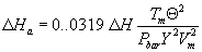 Where
0.0319 = (0.0567 in. Hg/ °R)(0.75 cfm) 2; ΔH = Average pressure
differential across the orifice meter, in. H20; Tm = Absolute
average DGM temperature, °R; Θ = Total sampling time, min; Pbar =
Barometric pressure, in. Hg; Y = DGM calibration factor,
dimensionless; Vm = Volume of gas sample as measured by DGM, dcf.
Where
0.0319 = (0.0567 in. Hg/ °R)(0.75 cfm) 2; ΔH = Average pressure
differential across the orifice meter, in. H20; Tm = Absolute
average DGM temperature, °R; Θ = Total sampling time, min; Pbar =
Barometric pressure, in. Hg; Y = DGM calibration factor,
dimensionless; Vm = Volume of gas sample as measured by DGM, dcf.
9.2.1.1 Before beginning the field test (a set of three runs usually constitutes a field test), operate the metering system (i.e., pump, volume meter, and orifice) at the ΔHa pressure differential for 10 minutes. Record the volume collected, the DGM temperature, and the barometric pressure. Calculate a DGM calibration check value, Yc, as follows:
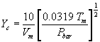 Where Yc
= DGM calibration check value, dimensionless; 10 = Run time, min.
Where Yc
= DGM calibration check value, dimensionless; 10 = Run time, min.
9.2.1.2 Compare the Yc value with the dry gas meter calibration factor Y to determine that: 0.97 Y <Yc <1.03Y. If the Yc value is not within this range, the volume metering system should be investigated before beginning the test.
9.2.2 Calibrated critical orifice. A calibrated critical orifice, calibrated against a wet test meter or spirometer and designed to be inserted at the inlet of the sampling meter box, may be used as a quality control check by following the procedure of section 16.2 of this method.
10.0 Calibration and Standardization Note:Maintain a laboratory log of all calibrations.
10.1 Probe nozzle. Probe nozzles shall be calibrated before their initial use in the field. Using a micrometer, measure the ID of the nozzle to the nearest 0.025 mm (0.001 in.). Make three separate measurements using different diameters each time, and obtain the average of the measurements. The difference between the high and low numbers shall not exceed 0.1 mm (0.004 in.). When nozzles become nicked, dented, or corroded, they shall be reshaped, sharpened, and recalibrated before use. Each nozzle shall be permanently and uniquely identified.
10.2 Pitot tube assembly. The Type S pitot tube assembly shall be calibrated according to the procedure outlined in section 10.1 of Method 2, 40 CFR part 60, appendix A.
10.3 Metering system.
10.3.1 Calibration prior to use. Before its initial use in the field, the metering system shall be calibrated as follows: Connect the metering system inlet to the outlet of a wet test meter that is accurate to within 1 percent. Refer to Figure 5-5 of Method 5, 40 CFR part 60, appendix A. The wet test meter should have a capacity of 30 liters/revolution (1 ft 3/rev). A spirometer of 400 liters (14 ft 3) or more capacity, or equivalent, may be used for this calibration, although a wet test meter is usually more practical. The wet test meter should be periodically calibrated with a spirometer or a liquid displacement meter to ensure the accuracy of the wet test meter. Spirometers or wet test meters of other sizes may be used, provided that the specified accuracies of the procedure are maintained. Run the metering system pump for about 15 minutes with the orifice manometer indicating a median reading, as expected in field use, to allow the pump to warm up and to permit the interior surface of the wet test meter to be thoroughly wetted. Then, at each of a minimum of three orifice manometer settings, pass an exact quantity of gas through the wet test meter and note the gas volume indicated by the DGM. Also note the barometric pressure and the temperatures of the wet test meter, the inlet of the DGM, and the outlet of the DGM. Select the highest and lowest orifice settings to bracket the expected field operating range of the orifice. Use a minimum volume of 0.15 m 3 (5 cf) at all orifice settings. Record all the data on a form similar to Figure 5-6 of Method 5, 40 CFR part 60, appendix A, and calculate Y (the DGM calibration factor) and ΔHa (the orifice calibration factor) at each orifice setting, as shown on Figure 5-6 of Method 5, 40 CFR part 60, appendix A. Allowable tolerances for individual Y and ΔHa values are given in Figure 5-6 of Method 5, 40 CFR part 60, appendix A. Use the average of the Y values in the calculations in section 12 of this method.
10.3.1.1 Before calibrating the metering system, it is suggested that a leak check be conducted. For metering systems having diaphragm pumps, the normal leak check procedure will not detect leakages within the pump. For these cases the following leak check procedure is suggested: make a 10-minute calibration run at 0.00057 m 3/min (0.02 cfm); at the end of the run, take the difference of the measured wet test meter and DGM volumes; divide the difference by 10 to get the leak rate. The leak rate should not exceed 0.00057 m 3/min (0.02 cfm).
10.3.2 Calibration after use. After each field use, the calibration of the metering system shall be checked by performing three calibration runs at a single, intermediate orifice setting (based on the previous field test) with the vacuum set at the maximum value reached during the test series. To adjust the vacuum, insert a valve between the wet test meter and the inlet of the metering system. Calculate the average value of the DGM calibration factor. If the value has changed by more than 5 percent, recalibrate the meter over the full range of orifice settings, as previously detailed.
Note:Alternative procedures, e.g., rechecking the orifice meter coefficient, may be used, subject to the approval of the Administrator.
10.3.3 Acceptable variation in calibration. If the DGM coefficient values obtained before and after a test series differ by more than 5 percent, either the test series shall be voided or calculations for the test series shall be performed using whichever meter coefficient value (i.e., before or after) gives the lower value of total sample volume.
10.4 Probe heater calibration. Use a heat source to generate air heated to selected temperatures that approximate those expected to occur in the sources to be sampled. Pass this air through the probe at a typical sample flow rate while measuring the probe inlet and outlet temperatures at various probe heater settings. For each air temperature generated, construct a graph of probe heating system setting versus probe outlet temperature. The procedure outlined in APTD-0576 can also be used. Probes constructed according to APTD-0581 need not be calibrated if the calibration curves in APTD-0576 are used. Also, probes with outlet temperature monitoring capabilities do not require calibration.
Note:The probe heating system shall be calibrated before its initial use in the field.
10.5 Temperature sensors. Use the procedure in Section 10.3 of Method 2, 40 CFR part 60, appendix A-1 to calibrate in-stack temperature sensors. Dial thermometers, such as are used for the DGM and condenser outlet, shall be calibrated against mercury-in-glass thermometers. An alternative mercury-free thermometer may be used if the thermometer is, at a minimum, equivalent in terms of performance or suitably effective for the specific temperature measurement application.
10.6 Barometer. Calibrate against a mercury barometer.
11.0 Analytical Procedure11.1 Record the data required on a sheet such as the one shown in Figure 315-1 of this method.
11.2 Handle each sample container as follows:
11.2.1 Container No. 1.
11.2.1.1 PM analysis. Leave the contents in the shipping container or transfer the filter and any loose PM from the sample container to a tared glass weighing dish. Desiccate for 24 hours in a desiccator containing anhydrous calcium sulfate. Weigh to a constant weight and report the results to the nearest 0.1 mg. For purposes of this section, the term “constant weight” means a difference of no more than 0.5 mg or 1 percent of total weight less tare weight, whichever is greater, between two consecutive weighings, with no less than 6 hours of desiccation time between weighings (overnight desiccation is a common practice). If a third weighing is required and it agrees within ±0.5 mg, then the results of the second weighing should be used. For quality assurance purposes, record and report each individual weighing; if more than three weighings are required, note this in the results for the subsequent MCEM results.
11.2.1.2 MCEM analysis. Transfer the filter and contents quantitatively into a beaker. Add 100 ml of methylene chloride and cover with aluminum foil. Sonicate for 3 minutes then allow to stand for 20 minutes. Set up the filtration apparatus. Decant the solution into a clean Buchner fritted funnel. Immediately pressure filter the solution through the tube into another clean, dry beaker. Continue decanting and pressure filtration until all the solvent is transferred. Rinse the beaker and filter with 10 to 20 ml methylene chloride, decant into the Buchner fritted funnel and pressure filter. Place the beaker on a low-temperature hot plate (maximum 40 °C) and slowly evaporate almost to dryness. Transfer the remaining last few milliliters of solution quantitatively from the beaker (using at least three aliquots of methylene chloride rinse) to a tared clean dry aluminum dish and evaporate to complete dryness. Remove from heat once solvent is evaporated. Reweigh the dish after a 30-minute equilibrium in the balance room and determine the weight to the nearest 0.1 mg. Conduct a methylene chloride blank run in an identical fashion.
11.2.2 Container No. 2.
11.2.2.1 PM analysis. Note the level of liquid in the container, and confirm on the analysis sheet whether leakage occurred during transport. If a noticeable amount of leakage has occurred, either void the sample or use methods, subject to the approval of the Administrator, to correct the final results. Measure the liquid in this container either volumetrically to ±1 ml or gravimetrically to 1 ±0.5 g. Transfer the contents to a tared 250 ml beaker and evaporate to dryness at ambient temperature and pressure. Desiccate for 24 hours, and weigh to a constant weight. Report the results to the nearest 0.1 mg.
11.2.2.2 MCEM analysis. Add 25 ml methylene chloride to the beaker and cover with aluminum foil. Sonicate for 3 minutes then allow to stand for 20 minutes; combine with contents of Container No. 2M and pressure filter and evaporate as described for Container 1 in section 11.2.1.2 of this method.
Notes for MCEM Analysis1. Light finger pressure only is necessary on 24/40 adaptor. A Chemplast adapter #15055-240 has been found satisfactory.
2. Avoid aluminum dishes made with fluted sides, as these may promote solvent “creep,” resulting in possible sample loss.
3. If multiple samples are being run, rinse the Buchner fritted funnel twice between samples with 5 ml solvent using pressure filtration. After the second rinse, continue the flow of air until the glass frit is completely dry. Clean the Buchner fritted funnels thoroughly after filtering five or six samples.
11.2.3 Container No. 3. Weigh the spent silica gel (or silica gel plus impinger) to the nearest 0.5 g using a balance. This step may be conducted in the field.
11.2.4 Container 3W (impinger water).
11.2.4.1 MCEM analysis. Transfer the solution into a 1,000 ml separatory funnel quantitatively with methylene chloride washes. Add enough solvent to total approximately 50 ml, if necessary. Shake the funnel for 1 minute, allow the phases to separate, and drain the solvent layer into a 250 ml beaker. Repeat the extraction twice. Evaporate with low heat (less than 40 °C) until near dryness. Transfer the remaining few milliliters of solvent quantitatively with small solvent washes into a clean, dry, tared aluminum dish and evaporate to dryness. Remove from heat once solvent is evaporated. Reweigh the dish after a 30-minute equilibration in the balance room and determine the weight to the nearest 0.1 mg.
11.2.5 Container 3S (solvent).
11.2.5.1 MCEM analysis. Transfer the mixed solvent to 250 ml beaker(s). Evaporate and weigh following the procedures detailed for container 3W in section 11.2.4 of this method.
11.2.6 Blank containers. Measure the distilled water, acetone, or methylene chloride in each container either volumetrically or gravimetrically. Transfer the “solvent” to a tared 250 ml beaker, and evaporate to dryness at ambient temperature and pressure. (Conduct a solvent blank on the distilled deionized water blank in an identical fashion to that described in section 11.2.4.1 of this method.) Desiccate for 24 hours, and weigh to a constant weight. Report the results to the nearest 0.l mg.
Note:The contents of Containers No. 2, 3W, and 3M as well as the blank containers may be evaporated at temperatures higher than ambient. If evaporation is done at an elevated temperature, the temperature must be below the boiling point of the solvent; also, to prevent “bumping,” the evaporation process must be closely supervised, and the contents of the beaker must be swirled occasionally to maintain an even temperature. Use extreme care, as acetone and methylene chloride are highly flammable and have a low flash point.
12.0 Data Analysis and Calculations12.1 Carry out calculations, retaining at least one extra decimal figure beyond that of the acquired data. Round off figures after the final calculation. Other forms of the equations may be used as long as they give equivalent results.
12.2 Nomenclature.
An = Cross-sectional area of nozzle, m 3 (ft 3). Bws = Water vapor in the gas stream, proportion by volume. Ca = Acetone blank residue concentration, mg/g. Cs = Concentration of particulate matter in stack gas, dry basis, corrected to standard conditions, g/dscm (g/dscf). I = Percent of isokinetic sampling. La = Maximum acceptable leakage rate for either a pretest leak check or for a leak check following a component change; equal to 0.00057 m 3/min (0.02 cfm) or 4 percent of the average sampling rate, whichever is less. Li = Individual leakage rate observed during the leak check conducted prior to the “i th” component change (I = l, 2, 3...n), m 3/min (cfm). Lp = Leakage rate observed during the post-test leak check, m 3/min (cfm). ma = Mass of residue of acetone after evaporation, mg. mn = Total amount of particulate matter collected, mg. Mw = Molecular weight of water, 18.0 g/g-mole (18.0 lb/lb-mole). Pbar = Barometric pressure at the sampling site, mm Hg (in Hg). Ps = Absolute stack gas pressure, mm Hg (in. Hg). Pstd = Standard absolute pressure, 760 mm Hg (29.92 in. Hg). R = Ideal gas constant, 0.06236 [(mm Hg)(m 3)]/[(°K) (g-mole)] '61' 21.85 [(in. Hg)(ft 3)]/[(°R)(lb-mole)'61' ]. Tm = Absolute average dry gas meter (DGM) temperature (see Figure 5-2 of Method 5, 40 CFR part 60, appendix A), °K (°R). Ts = Absolute average stack gas temperature (see Figure 5-2 of Method 5, 40 CFR part 60, appendix A), °K(°R). Tstd = Standard absolute temperature, 293 °K (528 °R). Va = Volume of acetone blank, ml. Vaw = Volume of acetone used in wash, ml. Vt = Volume of methylene chloride blank, ml. Vtw = Volume of methylene chloride used in wash, ml. Vlc = Total volume liquid collected in impingers and silica gel (see Figure 5-3 of Method 5, 40 CFR part 60, appendix A), ml. Vm = Volume of gas sample as measured by dry gas meter, dcm (dcf). Vm(std) = Volume of gas sample measured by the dry gas meter, corrected to standard conditions, dscm (dscf). Vw(std) = Volume of water vapor in the gas sample, corrected to standard conditions, scm (scf). Vs = Stack gas velocity, calculated by Equation 2-9 in Method 2, 40 CFR part 60, appendix A, using data obtained from Method 5, 40 CFR part 60, appendix A, m/sec (ft/sec). Wa = Weight of residue in acetone wash, mg. Y = Dry gas meter calibration factor. ΔH = Average pressure differential across the orifice meter (see Figure 5-2 of Method 5, 40 CFR part 60, appendix A), mm H2O (in H2O). ρa = Density of acetone, 785.1 mg/ml (or see label on bottle). ρw = Density of water, 0.9982 g/ml (0.00220l lb/ml). ρt = Density of methylene chloride, 1316.8 mg/ml (or see label on bottle). Θ = Total sampling time, min. Θ1 = Sampling time interval, from the beginning of a run until the first component change, min. Θ1 = Sampling time interval, between two successive component changes, beginning with the interval between the first and second changes, min. Θp = Sampling time interval, from the final (n th) component change until the end of the sampling run, min. 13.6 = Specific gravity of mercury. 60 = Sec/min. 100 = Conversion to percent.12.3 Average dry gas meter temperature and average orifice pressure drop. See data sheet (Figure 5-2 of Method 5, 40 CFR part 60, appendix A).
12.4 Dry gas volume. Correct the sample volume measured by the dry gas meter to standard conditions (20 °C, 760 mm Hg or 68 °F, 29.92 in Hg) by using Equation 315-1.
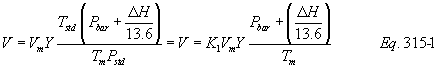 Where Kl
= 0.3858 °K/mm Hg for metric units, = 17.64 °R/in Hg for English
units. Note:
Where Kl
= 0.3858 °K/mm Hg for metric units, = 17.64 °R/in Hg for English
units. Note:
Equation 315-1 can be used as written unless the leakage rate observed during any of the mandatory leak checks (i.e., the post-test leak check or leak checks conducted prior to component changes) exceeds La. If Lp or Li exceeds La, Equation 315-1 must be modified as follows:
(a) Case I. No component changes made during sampling run. In this case, replace Vm in Equation 315-1 with the expression:
[Vm - (Lp - La) Θ](b) Case II. One or more component changes made during the sampling run. In this case, replace Vm in Equation 315-1 by the expression:
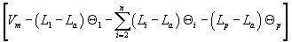 and
substitute only for those leakage rates (Li or Lp) which exceed La.
and
substitute only for those leakage rates (Li or Lp) which exceed La.
12.5 Volume of water vapor condensed.
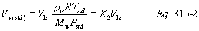 Where K2
= 0.001333 m 3/ml for metric units; = 0.04706 ft 3/ml for English
units. 12.6 Moisture content.
Where K2
= 0.001333 m 3/ml for metric units; = 0.04706 ft 3/ml for English
units. 12.6 Moisture content. 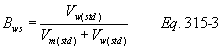 Note:
Note:
In saturated or water droplet-laden gas streams, two calculations of the moisture content of the stack gas shall be made, one from the impinger analysis (Equation 315-3), and a second from the assumption of saturated conditions. The lower of the two values of Bws shall be considered correct. The procedure for determining the moisture content based upon assumption of saturated conditions is given in section 4.0 of Method 4, 40 CFR part 60, appendix A. For the purposes of this method, the average stack gas temperature from Figure 5-2 of Method 5, 40 CFR part 60, appendix A may be used to make this determination, provided that the accuracy of the in-stack temperature sensor is ±1 °C (2 °F).
12.7 Acetone blank concentration.
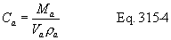
12.8 Acetone wash blank.
Wa = Ca Vaw ρa Eq. 315-512.9 Total particulate weight. Determine the total PM catch from the sum of the weights obtained from Containers l and 2 less the acetone blank associated with these two containers (see Figure 315-1).
Note:Refer to section 8.5.8 of this method to assist in calculation of results involving two or more filter assemblies or two or more sampling trains.
12.10 Particulate concentration.
cs = K3 mn/Vm(std) Eq. 315-6 where K = 0.001 g/mg for metric units; = 0.0154 gr/mg for English units.12.11 Conversion factors.
| From | To | Multiply by |
|---|---|---|
| ft 3 | m 3 | 0.02832 |
| gr | mg | 64.80004 |
| gr/ft 3 | mg/m 3 | 2288.4 |
| mg | g | 0.001 |
| gr | lb | 1.429 × 10⁻⁴ |
12.12 Isokinetic variation.
12.12.1 Calculation from raw data.
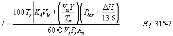 where K4
= 0.003454 [(mm Hg)(m 3)]/[(m1)(°K)] for metric units; = 0.002669
[(in Hg)(ft 3)]/[(m1)(°R)] for English units.
where K4
= 0.003454 [(mm Hg)(m 3)]/[(m1)(°K)] for metric units; = 0.002669
[(in Hg)(ft 3)]/[(m1)(°R)] for English units.
12.12.2 Calculation from intermediate values.
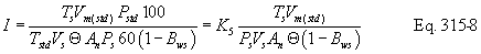 where K5
= 4.320 for metric units; = 0.09450 for English units.
where K5
= 4.320 for metric units; = 0.09450 for English units.
12.12.3 Acceptable results. If 90 percent ≤I ≤110 percent, the results are acceptable. If the PM or MCEM results are low in comparison to the standard, and “I” is over 110 percent or less than 90 percent, the Administrator may opt to accept the results. Reference 4 in the Bibliography may be used to make acceptability judgments. If “I” is judged to be unacceptable, reject the results, and repeat the test.
12.13 Stack gas velocity and volumetric flow rate. Calculate the average stack gas velocity and volumetric flow rate, if needed, using data obtained in this method and the equations in sections 5.2 and 5.3 of Method 2, 40 CFR part 60, appendix A.
12.14 MCEM results. Determine the MCEM concentration from the results from Containers 1, 2, 2M, 3W, and 3S less the acetone, methylene chloride, and filter blanks value as determined in the following equation:
mmcem = Smtotal − wa − wt − fb 13.0 Method Performance [Reserved] 14.0 Pollution Prevention [Reserved] 15.0 Waste Management [Reserved] 16.0 Alternative Procedures16.1 Dry gas meter as a calibration standard. A DGM may be used as a calibration standard for volume measurements in place of the wet test meter specified in section 16.1 of this method, provided that it is calibrated initially and recalibrated periodically as follows:
16.1.1 Standard dry gas meter calibration.
16.1.1.1. The DGM to be calibrated and used as a secondary reference meter should be of high quality and have an appropriately sized capacity, e.g., 3 liters/rev (0.1 ft 3/rev). A spirometer (400 liters or more capacity), or equivalent, may be used for this calibration, although a wet test meter is usually more practical. The wet test meter should have a capacity of 30 liters/rev (1 ft 3/rev) and be capable of measuring volume to within 1.0 percent; wet test meters should be checked against a spirometer or a liquid displacement meter to ensure the accuracy of the wet test meter. Spirometers or wet test meters of other sizes may be used, provided that the specified accuracies of the procedure are maintained.
16.1.1.2 Set up the components as shown in Figure 5-7 of Method 5, 40 CFR part 60, appendix A. A spirometer, or equivalent, may be used in place of the wet test meter in the system. Run the pump for at least 5 minutes at a flow rate of about 10 liters/min (0.35 cfm) to condition the interior surface of the wet test meter. The pressure drop indicated by the manometer at the inlet side of the DGM should be minimized (no greater than 100 mm H2O [4 in. H2O] at a flow rate of 30 liters/min [1 cfm]). This can be accomplished by using large-diameter tubing connections and straight pipe fittings.
16.1.1.3 Collect the data as shown in the example data sheet (see Figure 5-8 of Method 5, 40 CFR part 60, appendix A). Make triplicate runs at each of the flow rates and at no less than five different flow rates. The range of flow rates should be between 10 and 34 liters/min (0.35 and 1.2 cfm) or over the expected operating range.
16.1.1.4 Calculate flow rate, Q, for each run using the wet test meter volume, Vw, and the run time, q. Calculate the DGM coefficient, Yds, for each run. These calculations are as follows:
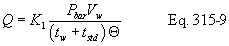
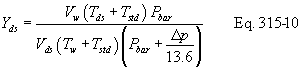 Where K1 = 0.3858
for international system of units (SI); 17.64 for English units;
Pbar = Barometric pressure, mm Hg (in Hg); Vw = Wet test meter
volume, liter (ft 3); tw = Average wet test meter temperature, °C
(°F); tstd = 273 °C for SI units; 460 °F for English units; Θ = Run
time, min; tds = Average dry gas meter temperature, °C (°F); Vds =
Dry gas meter volume, liter (ft 3); Δp = Dry gas meter inlet
differential pressure, mm H2O (in H2O).
Where K1 = 0.3858
for international system of units (SI); 17.64 for English units;
Pbar = Barometric pressure, mm Hg (in Hg); Vw = Wet test meter
volume, liter (ft 3); tw = Average wet test meter temperature, °C
(°F); tstd = 273 °C for SI units; 460 °F for English units; Θ = Run
time, min; tds = Average dry gas meter temperature, °C (°F); Vds =
Dry gas meter volume, liter (ft 3); Δp = Dry gas meter inlet
differential pressure, mm H2O (in H2O).
16.1.1.5 Compare the three Yds values at each of the flow rates and determine the maximum and minimum values. The difference between the maximum and minimum values at each flow rate should be no greater than 0.030. Extra sets of triplicate runs may be made in order to complete this requirement. In addition, the meter coefficients should be between 0.95 and 1.05. If these specifications cannot be met in three sets of successive triplicate runs, the meter is not suitable as a calibration standard and should not be used as such. If these specifications are met, average the three Yds values at each flow rate resulting in five average meter coefficients, Yds.
16.1.1.6 Prepare a curve of meter coefficient, Yds, versus flow rate, Q, for the DGM. This curve shall be used as a reference when the meter is used to calibrate other DGMs and to determine whether recalibration is required.
16.1.2 Standard dry gas meter recalibration.
16.1.2.1 Recalibrate the standard DGM against a wet test meter or spirometer annually or after every 200 hours of operation, whichever comes first. This requirement is valid provided the standard DGM is kept in a laboratory and, if transported, cared for as any other laboratory instrument. Abuse to the standard meter may cause a change in the calibration and will require more frequent recalibrations.
16.1.2.2 As an alternative to full recalibration, a two-point calibration check may be made. Follow the same procedure and equipment arrangement as for a full recalibration, but run the meter at only two flow rates (suggested rates are 14 and 28 liters/min [0.5 and 1.0 cfm]). Calculate the meter coefficients for these two points, and compare the values with the meter calibration curve. If the two coefficients are within 1.5 percent of the calibration curve values at the same flow rates, the meter need not be recalibrated until the next date for a recalibration check.
6.2 Critical orifices as calibration standards. Critical orifices may be used as calibration standards in place of the wet test meter specified in section 10.3 of this method, provided that they are selected, calibrated, and used as follows:
16.2.1 Selection of critical orifices.
16.2.1.1 The procedure that follows describes the use of hypodermic needles or stainless steel needle tubing that has been found suitable for use as critical orifices. Other materials and critical orifice designs may be used provided the orifices act as true critical orifices; i.e., a critical vacuum can be obtained, as described in section 7.2.2.2.3 of Method 5, 40 CFR part 60, appendix A. Select five critical orifices that are appropriately sized to cover the range of flow rates between 10 and 34 liters/min or the expected operating range. Two of the critical orifices should bracket the expected operating range. A minimum of three critical orifices will be needed to calibrate a Method 5 DGM; the other two critical orifices can serve as spares and provide better selection for bracketing the range of operating flow rates. The needle sizes and tubing lengths shown in Table 315-1 give the approximate flow rates indicated in the table.
16.2.1.2 These needles can be adapted to a Method 5 type sampling train as follows: Insert a serum bottle stopper, 13 × 20 mm sleeve type, into a 0.5 in Swagelok quick connect. Insert the needle into the stopper as shown in Figure 5-9 of Method 5, 40 CFR part 60, appendix A.
16.2.2 Critical orifice calibration. The procedure described in this section uses the Method 5 meter box configuration with a DGM as described in section 6.1.1.9 of this method to calibrate the critical orifices. Other schemes may be used, subject to the approval of the Administrator.
16.2.2.1 Calibration of meter box. The critical orifices must be calibrated in the same configuration as they will be used; i.e., there should be no connections to the inlet of the orifice.
16.2.2.1.1 Before calibrating the meter box, leak-check the system as follows: Fully open the coarse adjust valve and completely close the bypass valve. Plug the inlet. Then turn on the pump and determine whether there is any leakage. The leakage rate shall be zero; i.e., no detectable movement of the DGM dial shall be seen for 1 minute.
16.2.2.1.2 Check also for leakages in that portion of the sampling train between the pump and the orifice meter. See section 5.6 of Method 5, 40 CFR part 60, appendix A for the procedure; make any corrections, if necessary. If leakage is detected, check for cracked gaskets, loose fittings, worn 0-rings, etc. and make the necessary repairs.
16.2.2.1.3 After determining that the meter box is leakless, calibrate the meter box according to the procedure given in section 5.3 of Method 5, 40 CFR part 60, appendix A. Make sure that the wet test meter meets the requirements stated in section 7.1.1.1 of Method 5, 40 CFR part 60, appendix A. Check the water level in the wet test meter. Record the DGM calibration factor, Y.
16.2.2.2 Calibration of critical orifices. Set up the apparatus as shown in Figure 5-10 of Method 5, 40 CFR part 60, appendix A.
16.2.2.2.1 Allow a warm-up time of 15 minutes. This step is important to equilibrate the temperature conditions through the DGM.
16.2.2.2.2 Leak-check the system as in section 7.2.2.1.1 of Method 5, 40 CFR part 60, appendix A. The leakage rate shall be zero.
16.2.2.2.3 Before calibrating the critical orifice, determine its suitability and the appropriate operating vacuum as follows: turn on the pump, fully open the coarse adjust valve, and adjust the bypass valve to give a vacuum reading corresponding to about half of atmospheric pressure. Observe the meter box orifice manometer reading, DH. Slowly increase the vacuum reading until a stable reading is obtained on the meter box orifice manometer. Record the critical vacuum for each orifice. Orifices that do not reach a critical value shall not be used.
16.2.2.2.4 Obtain the barometric pressure using a barometer as described in section 6.1.2 of this method. Record the barometric pressure, Pbar, in mm Hg (in. Hg).
16.2.2.2.5 Conduct duplicate runs at a vacuum of 25 to 50 mm Hg (1 to 2 in. Hg) above the critical vacuum. The runs shall be at least 5 minutes each. The DGM volume readings shall be in increments of complete revolutions of the DGM. As a guideline, the times should not differ by more than 3.0 seconds (this includes allowance for changes in the DGM temperatures) to achieve ±0.5 percent in K′. Record the information listed in Figure 5-11 of Method 5, 40 CFR part 60, appendix A.
16.2.2.2.6 Calculate K′ using Equation 315-11.
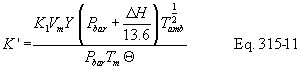 where K′
= Critical orifice coefficient, [m 3)(°K) 1/2]/[(mm Hg)(min)] [(ft
3)(°R) 1/2)]/[(in. Hg)(min)] Tamb = Absolute ambient temperature,
°K (°R).
where K′
= Critical orifice coefficient, [m 3)(°K) 1/2]/[(mm Hg)(min)] [(ft
3)(°R) 1/2)]/[(in. Hg)(min)] Tamb = Absolute ambient temperature,
°K (°R).
16.2.2.2.7 Average the K′ values. The individual K′ values should not differ by more than ±0.5 percent from the average.
16.2.3 Using the critical orifices as calibration standards.
16.2.3.1 Record the barometric pressure.
16.2.3.2 Calibrate the metering system according to the procedure outlined in sections 7.2.2.2.1 to 7.2.2.2.5 of Method 5, 40 CFR part 60, appendix A. Record the information listed in Figure 5-12 of Method 5, 40 CFR part 60, appendix A.
16.2.3.3 Calculate the standard volumes of air passed through the DGM and the critical orifices, and calculate the DGM calibration factor, Y, using the equations below:
Vm(std) = K1 Vm [Pbar + (ΔH/13.6)]/Tm Eq. 315-12 Vcr(std) = K′ (Pbar Θ)/Tamb 1/2 Eq. 315-13 Y = Vcr(std)/Vm(std) Eq. 315-14 where Vcr(std) = Volume of gas sample passed through the critical orifice, corrected to standard conditions, dscm (dscf). K′ = 0.3858 °K/mm Hg for metric units = 17.64 °R/in Hg for English units.16.2.3.4 Average the DGM calibration values for each of the flow rates. The calibration factor, Y, at each of the flow rates should not differ by more than ±2 percent from the average.
16.2.3.5 To determine the need for recalibrating the critical orifices, compare the DGM Y factors obtained from two adjacent orifices each time a DGM is calibrated; for example, when checking orifice 13/2.5, use orifices 12/10.2 and 13/5.1. If any critical orifice yields a DGM Y factor differing by more than 2 percent from the others, recalibrate the critical orifice according to section 7.2.2.2 of Method 5, 40 CFR part 60, appendix A.
17.0 References1. Addendum to Specifications for Incinerator Testing at Federal Facilities. PHS, NCAPC. December 6, 1967.
2. Martin, Robert M. Construction Details of Isokinetic Source-Sampling Equipment. Environmental Protection Agency. Research Triangle Park, NC. APTD-0581. April 1971.
3. Rom, Jerome J. Maintenance, Calibration, and Operation of Isokinetic Source Sampling Equipment. Environmental Protection Agency. Research Triangle Park, NC. APTD-0576. March 1972.
4. Smith, W.S., R.T. Shigehara, and W.F. Todd. A Method of Interpreting Stack Sampling Data. Paper Presented at the 63rd Annual Meeting of the Air Pollution Control Association, St. Louis, MO. June 14-19, 1970.
5. Smith, W.S., et al. Stack Gas Sampling Improved and Simplified With New Equipment. APCA Paper No. 67-119. 1967.
6. Specifications for Incinerator Testing at Federal Facilities. PHS, NCAPC. 1967.
7. Shigehara, R.T. Adjustment in the EPA Nomograph for Different Pitot Tube Coefficients and Dry Molecular Weights. Stack Sampling News 2:4-11. October 1974.
8. Vollaro, R.F. A Survey of Commercially Available Instrumentation for the Measurement of Low-Range Gas Velocities. U.S. Environmental Protection Agency, Emission Measurement Branch. Research Triangle Park, NC. November 1976 (unpublished paper).
9. Annual Book of ASTM Standards. Part 26. Gaseous Fuels; Coal and Coke; Atmospheric Analysis. American Society for Testing and Materials. Philadelphia, PA. 1974. pp. 617-622.
10. Felix, L.G., G.I. Clinard, G.E. Lacy, and J.D. McCain. Inertial Cascade Impactor Substrate Media for Flue Gas Sampling. U.S. Environmental Protection Agency. Research Triangle Park, NC 27711. Publication No. EPA-600/7-77-060. June 1977. 83 p.
11. Westlin, P.R., and R.T. Shigehara. Procedure for Calibrating and Using Dry Gas Volume Meters as Calibration Standards. Source Evaluation Society Newsletter. 3 (1):17-30. February 1978.
12. Lodge, J.P., Jr., J.B. Pate, B.E. Ammons, and G.A. Swanson. The Use of Hypodermic Needles as Critical Orifices in Air Sampling. J. Air Pollution Control Association. 16:197-200. 1966.
18.0 Tables, Diagrams, Flowcharts, and Validation Data
Table 315-1. Flow Rates for Various Needle Sizes and Tube Lengths.
| Gauge/length (cm) |
Flow rate (liters/min) |
Gauge/length (cm) |
Flow rate (liters/min) |
|---|---|---|---|
| 12/7.6 | 32.56 | 14/2.5 | 19.54 |
| 12/10.2 | 30.02 | 14/5.1 | 17.27 |
| 13/2.5 | 25.77 | 14/7.6 | 16.14 |
| 13/5.1 | 23.50 | 15/3.2 | 14.16 |
| 13/7.6 | 22.37 | 15/7.6 | 11.61 |
| 13/10.2 | 20.67 | 115/10.2 | 10.48 |

 Method 316 -
Sampling and Analysis for Formaldehyde Emissions From Stationary
Sources in the Mineral Wool and Wool Fiberglass Industries 1.0
Scope and Application
Method 316 -
Sampling and Analysis for Formaldehyde Emissions From Stationary
Sources in the Mineral Wool and Wool Fiberglass Industries 1.0
Scope and Application
This method is applicable to the determination of formaldehyde, CAS Registry number 50-00-0, from stationary sources in the mineral wool and wool fiber glass industries. High purity water is used to collect the formaldehyde. The formaldehyde concentrations in the stack samples are determined using the modified pararosaniline method. Formaldehyde can be detected as low as 8.8 × 10⁻¹⁰ lbs/cu ft (11.3 ppbv) or as high as 1.8 × 10⁻³ lbs/cu ft (23,000,000 ppbv), at standard conditions over a 1-hour sampling period, sampling approximately 30 cu ft.
2.0 Summary of MethodGaseous and particulate pollutants are withdrawn isokinetically from an emission source and are collected in high purity water. Formaldehyde present in the emissions is highly soluble in high purity water. The high purity water containing formaldehyde is then analyzed using the modified pararosaniline method. Formaldehyde in the sample reacts with acidic pararosaniline, and the sodium sulfite, forming a purple chromophore. The intensity of the purple color, measured spectrophotometrically, provides an accurate and precise measure of the formaldehyde concentration in the sample.
3.0 DefinitionsSee the definitions in the General Provisions of this Subpart.
4.0 InterferencesSulfite and cyanide in solution interfere with the pararosaniline method. A procedure to overcome the interference by each compound has been described by Miksch, et al.
5.0 Safety [Reserved] 6.0 Apparatus and Materials6.1 A schematic of the sampling train is shown in Figure 1. This sampling train configuration is adapted from EPA Method 5, 40 CFR part 60, appendix A, procedures.
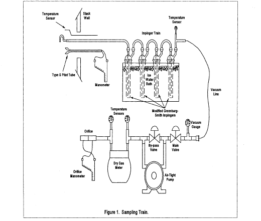
The sampling train consists of the following components: probe nozzle, probe liner, pitot tube, differential pressure gauge, impingers, metering system, barometer, and gas density determination equipment.
6.1.1 Probe Nozzle: Quartz, glass, or stainless steel with sharp, tapered (30 ° angle) leading edge. The taper shall be on the outside to preserve a constant inner diameter. The nozzle shall be buttonhook or elbow design. A range of nozzle sizes suitable for isokinetic sampling should be available in increments of 0.15 cm ( 1/16 in), e.g., 0.32 to 1.27 cm ( 1/8 to 1/2 in), or larger if higher volume sampling trains are used. Each nozzle shall be calibrated according to the procedure outlined in Section 10.1.
6.1.2 Probe Liner: Borosilicate glass or quartz shall be used for the probe liner. The probe shall be maintained at a temperature of 120 °C ±14 °C (248 °F ±25 °F).
6.1.3 Pitot Tube: The pitot tube shall be Type S, as described in Section 2.1 of EPA Method 2, 40 CFR part 60, appendix A, or any other appropriate device. The pitot tube shall be attached to the probe to allow constant monitoring of the stack gas velocity. The impact (high pressure) opening plane of the pitot tube shall be even with or above the nozzle entry plane (see Figure 2-6b, EPA Method 2, 40 CFR part 60, appendix A) during sampling. The Type S pitot tube assembly shall have a known coefficient, determined as outlined in Section 4 of EPA Method 2, 40 CFR part 60, appendix A.
6.1.4 Differential Pressure Gauge: The differential pressure gauge shall be an inclined manometer or equivalent device as described in Section 2.2 of EPA Method 2, 40 CFR part 60, appendix A. One manometer shall be used for velocity-head reading and the other for orifice differential pressure readings.
6.1.5 Impingers: The sampling train requires a minimum of four impingers, connected as shown in Figure 1, with ground glass (or equivalent) vacuum-tight fittings. For the first, third, and fourth impingers, use the Greenburg-Smith design, modified by replacing the tip with a 1.3 cm inside diameters ( 1/2 in) glass tube extending to 1.3 cm ( 1/2 in) from the bottom of the flask. For the second impinger, use a Greenburg-Smith impinger with the standard tip. Place a thermometer capable of measuring temperature to within 1 °C (2 °F) at the outlet of the fourth impinger for monitoring purposes.
6.1.6 Metering System: The necessary components are a vacuum gauge, leak-free pump, thermometers capable of measuring temperatures within 3 °C (5.4 °F), dry-gas meter capable of measuring volume to within 1 percent, and related equipment as shown in Figure 1. At a minimum, the pump should be capable of 4 cfm free flow, and the dry gas meter should have a recording capacity of 0-999.9 cu ft with a resolution of 0.005 cu ft. Other metering systems may be used which are capable of maintaining sample volumes to within 2 percent. The metering system may be used in conjunction with a pitot tube to enable checks of isokinetic sampling rates.
6.1.7 Barometer: The barometer may be mercury, aneroid, or other barometer capable of measuring atmospheric pressure to within 2.5 mm Hg (0.1 in Hg). In many cases, the barometric reading may be obtained from a nearby National Weather Service Station, in which case the station value (which is the absolute barometric pressure) is requested and an adjustment for elevation differences between the weather station and sampling point is applied at a rate of minus 2.5 mm Hg (0.1 in Hg) per 30 m (100 ft) elevation increase (rate is plus 2.5 mm Hg per 30 m (100 ft) of elevation decrease).
6.1.8 Gas Density Determination Equipment: Temperature sensor and pressure gauge (as described in Sections 2.3 and 2.3 of EPA Method 2, 40 CFR part 60, appendix A), and gas analyzer, if necessary (as described in EPA Method 3, 40 CFR part 60, appendix A). The temperature sensor ideally should be permanently attached to the pitot tube or sampling probe in a fixed configuration such that the top of the sensor extends beyond the leading edge of the probe sheath and does not touch any metal. Alternatively, the sensor may be attached just prior to use in the field. Note, however, that if the temperature sensor is attached in the field, the sensor must be placed in an interference-free arrangement with respect to the Type S pitot openings (see Figure 2-7, EPA Method 2, 40 CFR part 60, appendix A). As a second alternative, if a difference of no more than 1 percent in the average velocity measurement is to be introduced, the temperature gauge need not be attached to the probe or pitot tube.
6.2 Sample Recovery
6.2.1 Probe Liner: Probe nozzle and brushes; bristle brushes with stainless steel wire handles are required. The probe brush shall have extensions of stainless steel, Teflon TM, or inert material at least as long as the probe. The brushes shall be properly sized and shaped to brush out the probe liner, the probe nozzle, and the impingers.
6.2.2 Wash Bottles: One wash bottle is required. Polyethylene, Teflon TM, or glass wash bottles may be used for sample recovery.
6.2.3 Graduated Cylinder and/or Balance: A graduated cylinder or balance is required to measure condensed water to the nearest 1 ml or 1 g. Graduated cylinders shall have division not >2 ml. Laboratory balances capable of weighing to ±0.5 g are required.
6.2.4 Polyethylene Storage Containers: 500 ml wide-mouth polyethylene bottles are required to store impinger water samples.
6.2.5 Rubber Policeman and Funnel: A rubber policeman and funnel are required to aid the transfer of material into and out of containers in the field.
6.3 Sample Analysis
6.3.1 Spectrophotometer - B&L 70, 710, 2000, etc., or equivalent; 1 cm pathlength cuvette holder.
6.3.2 Disposable polystyrene cuvettes, pathlengh 1 cm, volume of about 4.5 ml.
6.3.3 Pipettors - Fixed-volume Oxford pipet (250 µl; 500 µl; 1000 µl); adjustable volume Oxford or equivalent pipettor 1-5 ml model, set to 2.50 ml.
6.3.4 Pipet tips for pipettors above.
6.3.5 Parafilm, 2 ° wide; cut into about 1” squares.
7.0 Reagents7.1 High purity water: All references to water in this method refer to high purity water (ASTM Type I water or equivalent). The water purity will dictate the lower limits of formaldehyde quantification.
7.2 Silica Gel: Silica gel shall be indicting type, 6-16 mesh. If the silica gel has been used previously, dry at 175 °C (350 °F) for 2 hours before using. New silica gel may be used as received. Alternatively, other types of desiccants (equivalent or better) may be used.
7.3 Crushed Ice: Quantities ranging from 10-50 lbs may be necessary during a sampling run, depending upon ambient temperature. Samples which have been taken must be stored and shipped cold; sufficient ice for this purpose must be allowed.
7.4 Quaternary ammonium compound stock solution: Prepare a stock solution of dodecyltrimethylammonium chloride (98 percent minimum assay, reagent grade) by dissolving 1.0 gram in 1000 ml water. This solution contains nominally 1000 µg/ml quaternary ammonium compound, and is used as a biocide for some sources which are prone to microbial contamination.
7.5 Pararosaniline: Weigh 0.16 grams pararosaniline (free base; assay of 95 percent or greater, C.I. 42500; Sigma P7632 has been found to be acceptable) into a 100 ml flask. Exercise care, since pararosaniline is a dye and will stain. Using a wash bottle with high-purity water, rinse the walls of the flask. Add no more than 25 ml water. Then, carefully add 20 ml of concentrated hydrochloric acid to the flask. The flask will become warm after the addition of acid. Add a magnetic stir bar to the flask, cap, and place on a magnetic stirrer for approximately 4 hours. Then, add additional water so the total volume is 100 ml. This solution is stable for several months when stored tightly capped at room temperature.
7.6 Sodium sulfite: Weigh 0.10 grams anhydrous sodium sulfite into a 100 ml flask. Dilute to the mark with high purity water. Invert 15-20 times to mix and dissolve the sodium sulfite. This solution must be prepared fresh every day.
7.7 Formaldehyde standard solution: Pipet exactly 2.70 ml of 37 percent formaldehyde solution into a 1000 ml volumetric flask which contains about 500 ml of high-purity water. Dilute to the mark with high-purity water. This solution contains nominally 1000 µg/ml of formaldehyde, and is used to prepare the working formaldehyde standards. The exact formaldehyde concentration may be determined if needed by suitable modification of the sodium sulfite method (Reference: J.F. Walker, Formaldehyde (Third Edition), 1964.). The 1000 µg/ml formaldehyde stock solution is stable for at least a year if kept tightly closed, with the neck of the flask sealed with Parafilm. Store at room temperature.
7.8 Working formaldehyde standards: Pipet exactly 10.0 ml of the 1000 µg/ml formaldehyde stock solution into a 100 ml volumetric flask which is about half full of high-purity water. Dilute to the mark with high-purity water, and invert 15-20 times to mix thoroughly. This solution contains nominally 100 µg/ml formaldehyde. Prepare the working standards from this 100 µg/ml standard solution and using the Oxford pipets:
| Working standard, µ/mL | µL or 100 µg/mL solution | Volumetric flask volume (dilute to mark with water) |
|---|---|---|
| 0.250 | 250 | 100 |
| 0.500 | 500 | 100 |
| 1.00 | 1000 | 100 |
| 2.00 | 2000 | 100 |
| 3.00 | 1500 | 50 |
8.1 Because of the complexity of this method, field personnel should be trained in and experienced with the test procedures in order to obtain reliable results.
8.2 Laboratory Preparation8.2.1 All the components shall be maintained and calibrated according to the procedure described in APTD-0576, unless otherwise specified.
8.2.2 Weigh several 200 to 300 g portions of silica gel in airtight containers to the nearest 0.5 g. Record on each container the total weight of the silica gel plus containers. As an alternative to preweighing the silica gel, it may instead be weighed directly in the impinger or sampling holder just prior to train assembly.
8.3 Preliminary Field Determinations
8.3.1 Select the sampling site and the minimum number of sampling points according to EPA Method 1, 40 CFR part 60, appendix A, or other relevant criteria. Determine the stack pressure, temperature, and range of velocity heads using EPA Method 2, 40 CFR part 60, appendix A. A leak-check of the pitot lines according to Section 3.1 of EPA Method 2, 40 CFR part 60, appendix A, must be performed. Determine the stack gas moisture content using EPA Approximation Method 4,40 CFR part 60, appendix A, or its alternatives to establish estimates of isokinetic sampling rate settings. Determine the stack gas dry molecular weight, as described in EPA Method 2, 40 CFR part 60, appendix A, Section 3.6. If integrated EPA Method 3, 40 CFR part 60, appendix A, sampling is used for molecular weight determination, the integrated bag sample shall be taken simultaneously with, and for the same total length of time as, the sample run.
8.3.2 Select a nozzle size based on the range of velocity heads so that it is not necessary to change the nozzle size in order to maintain isokinetic sampling rates below 28 l/min (1.0 cfm). During the run do not change the nozzle. Ensure that the proper differential pressure gauge is chosen for the range of velocity heads encountered (see Section 2.2 of EPA Method 2, 40 CFR part 60, appendix A).
8.3.3 Select a suitable probe liner and probe length so that all traverse points can be sampled. For large stacks, to reduce the length of the probe, consider sampling from opposite sides of the stack.
8.3.4 A minimum of 30 cu ft of sample volume is suggested for emission sources with stack concentrations not greater than 23,000,000 ppbv. Additional sample volume shall be collected as necessitated by the capacity of the water reagent and analytical detection limit constraint. Reduced sample volume may be collected as long as the final concentration of formaldehyde in the stack sample is greater than 10 (ten) times the detection limit.
8.3.5 Determine the total length of sampling time needed to obtain the identified minimum volume by comparing the anticipated average sampling rate with the volume requirement. Allocate the same time to all traverse points defined by EPA Method 1, 40 CFR part 60, appendix A. To avoid timekeeping errors, the length of time sampled at each traverse point should be an integer or an integer plus 0.5 min.
8.3.6 In some circumstances (e.g., batch cycles) it may be necessary to sample for shorter times at the traverse points and to obtain smaller gas-volume samples. In these cases, careful documentation must be maintained in order to allow accurate calculations of concentrations.
8.4 Preparation of Collection Train
8.4.1 During preparation and assembly of the sampling train, keep all openings where contamination can occur covered with Teflon TM film or aluminum foil until just prior to assembly or until sampling is about to begin.
8.4.2 Place 100 ml of water in each of the first two impingers, and leave the third impinger empty. If additional capacity is required for high expected concentrations of formaldehyde in the stack gas, 200 ml of water per impinger may be used or additional impingers may be used for sampling. Transfer approximately 200 to 300 g of pre-weighed silica gel from its container to the fourth impinger. Care should be taken to ensure that the silica gel is not entrained and carried out from the impinger during sampling. Place the silica gel container in a clean place for later use in the sample recovery. Alternatively, the weight of the silica gel plus impinger may be determined to the nearest 0.5 g and recorded.
8.4.3 With a glass or quartz liner, install the selected nozzle using a Viton-A O-ring when stack temperatures are <260 °C (500 °F) and a woven glass-fiber gasket when temperatures are higher. See APTD-0576 for details. Other connection systems utilizing either 316 stainless steel or Teflon TM ferrules may be used. Mark the probe with heat-resistant tape or by some other method to denote the proper distance into the stack or duct for each sampling point.
8.4.4 Assemble the train as shown in Figure 1. During assembly, a very light coating of silicone grease may be used on ground-glass joints of the impingers, but the silicone grease should be limited to the outer portion (see APTD-0576) of the ground-glass joints to minimize silicone grease contamination. If necessary, Teflon TM tape may be used to seal leaks. Connect all temperature sensors to an appropriate potentiometer/display unit. Check all temperature sensors at ambient temperatures.
8.4.5 Place crushed ice all around the impingers.
8.4.6 Turn on and set the probe heating system at the desired operating temperature. Allow time for the temperature to stabilize.
8.5 Leak-Check Procedures
8.5.1 Pre-test Leak-check: Recommended, but not required. If the tester elects to conduct the pre-test leak-check, the following procedure shall be used.
8.5.1.1 After the sampling train has been assembled, turn on and set probe heating system at the desired operating temperature. Allow time for the temperature to stabilize. If a Viton-a O-ring or other leak-free connection is used in assembling the probe nozzle to the probe liner, leak-check the train at the sampling site by plugging the nozzle and pulling a 381 mm Hg (15 in Hg) vacuum.
Note:A lower vacuum may be used, provided that the lower vacuum is not exceeded during the test.
If a woven glass fiber gasket is used, do not connect the probe to the train during the leak-check. Instead, leak-check the train by first attaching a carbon-filled leak-check impinger to the inlet and then plugging the inlet and pulling a 381 mm Hg (15 in Hg) vacuum. (A lower vacuum may be used if this lower vacuum is not exceeded during the test.) Next connect the probe to the train and leak-check at about 25 mm Hg (1 in Hg) vacuum. Alternatively, leak-check the probe with the rest of the sampling train in one step at 381 mm Hg (15 in Hg) vacuum. Leakage rates in excess of (a) 4 percent of the average sampling rate or (b) 0.00057 m 3/min (0.02 cfm), whichever is less, are unacceptable.
8.5.1.2 The following leak-check instructions for the sampling train described in APTD-0576 and APTD-0581 may be helpful. Start the pump with the fine-adjust valve fully open and coarse-valve completely closed. Partially open the coarse-adjust valve and slowly close the fine-adjust valve until the desired vacuum is reached. Do not reverse direction of the fine-adjust valve, as liquid will back up into the train. If the desired vacuum is exceeded, either perform the leak-check at this higher vacuum or end the leak-check, as described below, and start over.
8.5.1.3 When the leak-check is completed, first slowly remove the plug from the inlet to the probe. When the vacuum drops to 127 mm (5 in) Hg or less, immediately close the coarse-adjust valve. Switch off the pumping system and reopen the fine-adjust valve. Do not reopen the fine-adjust valve until the coarse-adjust valve has been closed to prevent the liquid in the impingers from being forced backward in the sampling line and silica gel from being entrained backward into the third impinger.
8.5.2 Leak-checks During Sampling Run:
8.5.2.1 If, during the sampling run, a component change (e.g., impinger) becomes necessary, a leak-check shall be conducted immediately after the interruption of sampling and before the change is made. The leak-check shall be done according to the procedure described in Section 10.3.3, except that it shall be done at a vacuum greater than or equal to the maximum value recorded up to that point in the test. If the leakage rate is found to be no greater than 0.0057 m 3/min (0.02 cfm) or 4 percent of the average sampling rate (whichever is less), the results are acceptable. If a higher leakage rate is obtained, the tester must void the sampling run.
Note:Any correction of the sample volume by calculation reduces the integrity of the pollutant concentration data generated and must be avoided.
8.5.2.2 Immediately after component changes, leak-checks are optional. If performed, the procedure described in section 8.5.1.1 shall be used.
8.5.3 Post-test Leak-check:
8.5.3.1 A leak-check is mandatory at the conclusion of each sampling run. The leak-check shall be done with the same procedures as the pre-test leak-check, except that the post-test leak-check shall be conducted at a vacuum greater than or equal to the maximum value reached during the sampling run. If the leakage rate is found to be no greater than 0.00057 m 3/min (0.02 cfm) or 4 percent of the average sampling rate (whichever is less), the results are acceptable. If, however, a higher leakage rate is obtained, the tester shall record the leakage rate and void the sampling run.
8.6 Sampling Train Operation
8.6.1 During the sampling run, maintain an isokinetic sampling rate to within 10 percent of true isokinetic, below 28 l/min (1.0 cfm). Maintain a temperature around the probe of 120 °C ±14 °C (248 ° ±25 °F).
8.6.2 For each run, record the data on a data sheet such as the one shown in Figure 2. Be sure to record the initial dry-gas meter reading. Record the dry-gas meter readings at the beginning and end of each sampling time increment, when changes in flow rates are made, before and after each leak-check, and when sampling is halted. Take other readings required by Figure 2 at least once at each sample point during each time increment and additional readings when significant adjustments (20 percent variation in velocity head readings) necessitate additional adjustments in flow rate. Level and zero the manometer. Because the manometer level and zero may drift due to vibrations and temperature changes, make periodic checks during the traverse.
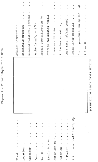
| Traverse point number | Sampling time (e) min. |
Vacuum mm Hg (in. Hg) |
Stack temperature
(T) °C (°F) |
Velocity head (ΔP) mm (in) H2O |
Pressure
differential across orifice meter mm H2O (in. H2O) |
Gas sample
volume m 3 (ft 3) |
Gas sample temperature at dry gas meter | Filter holder
temperature °C (°F) |
Temperature of
gas leaving condenser or last impinger °C (°F) |
|
|---|---|---|---|---|---|---|---|---|---|---|
| Inlet °C (°F) |
Outlet °C (°F) |
|||||||||
| Total | Avg. | Avg. | ||||||||
| Average | Avg. | |||||||||
8.6.3 Clean the stack access ports prior to the test run to eliminate the chance of sampling deposited material. To begin sampling, remove the nozzle cap, verify that the probe heating system are at the specified temperature, and verify that the pitot tube and probe are properly positioned. Position the nozzle at the first traverse point, with the tip pointing directly into the gas stream. Immediately start the pump and adjust the flow to isokinetic conditions. Nomographs, which aid in the rapid adjustment of the isokinetic sampling rate without excessive computations, are available. These nomographs are designed for use when the Type S pitot tube coefficient is 0.84 ±0.02 and the stack gas equivalent density (dry molecular weight) is equal to 29 ±4. APTD-0576 details the procedure for using the nomographs. If the stack gas molecular weight and the pitot tube coefficient are outside the above ranges, do not use the nomographs unless appropriate steps are taken to compensate for the deviations.
8.6.4 When the stack is under significant negative pressure (equivalent to the height of the impinger stem), take care to close the coarse-adjust valve before inserting the probe into the stack in order to prevent liquid from backing up through the train. If necessary, a low vacuum on the train may have to be started prior to entering the stack.
8.6.5 When the probe is in position, block off the openings around the probe and stack access port to prevent unrepresentative dilution of the gas stream.
8.6.6 Traverse the stack cross section, as required by EPA Method 1, 40 CFR part 60, appendix A, being careful not to bump the probe nozzle into the stack walls when sampling near the walls or when removing or inserting the probe through the access port, in order to minimize the chance of extracting deposited material.
8.6.7 During the test run, make periodic adjustments to keep the temperature around the probe at the proper levels. Add more ice and, if necessary, salt, to maintain a temperature of <20 °C (68 °F) at the silica gel outlet.
8.6.8 A single train shall be used for the entire sampling run, except in cases where simultaneous sampling is required in two or more separate ducts or at two or more different locations within the same duct, or in cases where equipment failure necessitates a change of trains. An additional train or trains may also be used for sampling when the capacity of a single train is exceeded.
8.6.9 When two or more trains are used, separate analyses of components from each train shall be performed. If multiple trains have been used because the capacity of a single train would be exceeded, first impingers from each train may be combined, and second impingers from each train may be combined.
8.6.10 At the end of the sampling run, turn off the coarse-adjust valve, remove the probe and nozzle from the stack, turn off the pump, record the final dry gas meter reading, and conduct a post-test leak-check. Also, check the pitot lines as described in EPA Method 2, 40 CFR part 60, appendix A. The lines must pass this leak-check in order to validate the velocity-head data.
8.6.11 Calculate percent isokineticity (see Method 2) to determine whether the run was valid or another test should be made.
8.7 Sample Preservation and Handling
8.7.1 Samples from most sources applicable to this method have acceptable holding times using normal handling practices (shipping samples iced, storing in refrigerator at 2 °C until analysis). However, forming section stacks and other sources using waste water sprays may be subject to microbial contamination. For these sources, a biocide (quaternary ammonium compound solution) may be added to collected samples to improve sample stability and method ruggedness.
8.7.2 Sample holding time: Samples should be analyzed within 14 days of collection. Samples must be refrigerated/kept cold for the entire period preceding analysis. After the samples have been brought to room temperature for analysis, any analyses needed should be performed on the same day. Repeated cycles of warming the samples to room temperature/refrigerating/rewarming, then analyzing again, etc., have not been investigated in depth to evaluate if analyte levels remain stable for all sources.
8.7.3 Additional studies will be performed to evaluate whether longer sample holding times are feasible for this method.
8.8 Sample Recovery
8.8.1 Preparation:
8.8.1.1 Proper cleanup procedure begins as soon as the probe is removed from the stack at the end of the sampling period. Allow the probe to cool. When the probe can be handled safely, wipe off all external particulate matter near the tip of the probe nozzle and place a cap over the tip to prevent losing or gaining particulate matter. Do not cap the probe tightly while the sampling train is cooling because a vacuum will be created, drawing liquid from the impingers back through the sampling train.
8.8.1.2 Before moving the sampling train to the cleanup site, remove the probe from the sampling train and cap the open outlet, being careful not to lose any condensate that might be present. Remove the umbilical cord from the last impinger and cap the impinger. If a flexible line is used, let any condensed water or liquid drain into the impingers. Cap off any open impinger inlets and outlets. Ground glass stoppers, Teflon TM caps, or caps of other inert materials may be used to seal all openings.
8.8.1.3 Transfer the probe and impinger assembly to an area that is clean and protected from wind so that the chances of contaminating or losing the sample are minimized.
8.8.1.4 Inspect the train before and during disassembly, and note any abnormal conditions.
8.8.1.5 Save a portion of the washing solution (high purity water) used for cleanup as a blank.
8.8.2 Sample Containers:
8.8.2.1 Container 1: Probe and Impinger Catches. Using a graduated cylinder, measure to the nearest ml, and record the volume of the solution in the first three impingers. Alternatively, the solution may be weighed to the nearest 0.5 g. Include any condensate in the probe in this determination. Transfer the combined impinger solution from the graduated cylinder into the polyethylene bottle. Taking care that dust on the outside of the probe or other exterior surfaces does not get into the sample, clean all surfaces to which the sample is exposed (including the probe nozzle, probe fitting, probe liner, first three impingers, and impinger connectors) with water. Use less than 400 ml for the entire waste (250 ml would be better, if possible). Add the rinse water to the sample container.
8.8.2.1.1 Carefully remove the probe nozzle and rinse the inside surface with water from a wash bottle. Brush with a bristle brush and rinse until the rinse shows no visible particles, after which make a final rinse of the inside surface. Brush and rinse the inside parts of the Swagelok (or equivalent) fitting with water in a similar way.
8.8.2.1.2 Rinse the probe liner with water. While squirting the water into the upper end of the probe, tilt and rotate the probe so that all inside surfaces will be wetted with water. Let the water drain from the lower end into the sample container. The tester may use a funnel (glass or polyethylene) to aid in transferring the liquid washes to the container. Follow the rinse with a bristle brush. Hold the probe in an inclined position, and squirt water into the upper end as the probe brush is being pushed with a twisting action through the probe. Hold the sample container underneath the lower end of the probe, and catch any water and particulate matter that is brushed from the probe. Run the brush through the probe three times or more. Rinse the brush with water and quantitatively collect these washings in the sample container. After the brushing, make a final rinse of the probe as describe above.
Note:Two people should clean the probe in order to minimize sample losses. Between sampling runs, brushes must be kept clean and free from contamination.
8.8.2.1.3 Rinse the inside surface of each of the first three impingers (and connecting tubing) three separate times. Use a small portion of water for each rinse, and brush each surface to which the sample is exposed with a bristle brush to ensure recovery of fine particulate matter. Make a final rinse of each surface and of the brush, using water.
8.8.2.1.4 After all water washing and particulate matter have been collected in the sample container, tighten the lid so the sample will not leak out when the container is shipped to the laboratory. Mark the height of the fluid level to determine whether leakage occurs during transport. Label the container clearly to identify its contents.
8.8.2.1.5 If the first two impingers are to be analyzed separately to check for breakthrough, separate the contents and rinses of the two impingers into individual containers. Care must be taken to avoid physical carryover from the first impinger to the second. Any physical carryover of collected moisture into the second impinger will invalidate a breakthrough assessment.
8.8.2.2 Container 2: Sample Blank. Prepare a blank by using a polyethylene container and adding a volume of water equal to the total volume in Container 1. Process the blank in the same manner as Container 1.
8.8.2.3 Container 3: Silica Gel. Note the color of the indicating silica gel to determine whether it has been completely spent and make a notation of its condition. The impinger containing the silica gel may be used as a sample transport container with both ends sealed with tightly fitting caps or plugs. Ground-glass stoppers or Teflon TM caps maybe used. The silica gel impinger should then be labeled, covered with aluminum foil, and packaged on ice for transport to the laboratory. If the silica gel is removed from the impinger, the tester may use a funnel to pour the silica gel and a rubber policeman to remove the silica gel from the impinger. It is not necessary to remove the small amount of dust particles that may adhere to the impinger wall and are difficult to remove. Since the gain in weight is to be used for moisture calculations, do not use water or other liquids to transfer the silica gel. If a balance is available in the field, the spent silica gel (or silica gel plus impinger) may be weighed to the nearest 0.5 g.
8.8.2.4 Sample containers should be placed in a cooler, cooled by (although not in contact with) ice. Putting sample bottles in Zip-Lock TM bags can aid in maintaining the integrity of the sample labels. Sample containers should be placed vertically to avoid leakage during shipment. Samples should be cooled during shipment so they will be received cold at the laboratory. It is critical that samples be chilled immediately after recovery. If the source is susceptible to microbial contamination from wash water (e.g. forming section stack), add biocide as directed in section 8.2.5.
8.8.2.5 A quaternary ammonium compound can be used as a biocide to stabilize samples against microbial degradation following collection. Using the stock quaternary ammonium compound (QAC) solution; add 2.5 ml QAC solution for every 100 ml of recovered sample volume (estimate of volume is satisfactory) immediately after collection. The total volume of QAC solution must be accurately known and recorded, to correct for any dilution caused by the QAC solution addition.
8.8.3 Sample Preparation for Analysis 8.8.3.1 The sample should be refrigerated if the analysis will not be performed on the day of sampling. Allow the sample to warm at room temperature for about two hours (if it has been refrigerated) prior to analyzing.
8.8.3.2 Analyze the sample by the pararosaniline method, as described in Section 11. If the color-developed sample has an absorbance above the highest standard, a suitable dilution in high purity water should be prepared and analyzed.
9.0 Quality Control9.1 Sampling: See EPA Manual 600/4-77-02b for Method 5 quality control.
9.2 Analysis: The quality assurance program required for this method includes the analysis of the field and method blanks, and procedure validations. The positive identification and quantitation of formaldehyde are dependent on the integrity of the samples received and the precision and accuracy of the analytical methodology. Quality assurance procedures for this method are designed to monitor the performance of the analytical methodology and to provide the required information to take corrective action if problems are observed in laboratory operations or in field sampling activities.
9.2.1 Field Blanks: Field blanks must be submitted with the samples collected at each sampling site. The field blanks include the sample bottles containing aliquots of sample recover water, and water reagent. At a minimum, one complete sampling train will be assembled in the field staging area, taken to the sampling area, and leak-checked at the beginning and end of the testing (or for the same total number of times as the actual sampling train). The probe of the blank train must be heated during the sample test. The train will be recovered as if it were an actual test sample. No gaseous sample will be passed through the blank sampling train.
9.2.2 Blank Correction: The field blank formaldehyde concentrations will be subtracted from the appropriate sample formaldehyde concentrations. Blank formaldehyde concentrations above 0.25 µg/ml should be considered suspect, and subtraction from the sample formaldehyde concentrations should be performed in a manner acceptable to the Administrator.
9.2.3 Method Blanks: A method blank must be prepared for each set of analytical operations, to evaluate contamination and artifacts that can be derived from glassware, reagents, and sample handling in the laboratory.
10 Calibration10.1 Probe Nozzle: Probe nozzles shall be calibrated before their initial use in the field. Using a micrometer, measure the inside diameter of the nozzle to the nearest 0.025 mm (0.001 in). Make measurements at three separate places across the diameter and obtain the average of the measurements. The difference between the high and low numbers shall not exceed 0.1 mm (0.004 in). When the nozzle becomes nicked or corroded, it shall be repaired and calibrated, or replaced with a calibrated nozzle before use. Each nozzle must be permanently and uniquely identified.
10.2 Pitot Tube: The Type S pitot tube assembly shall be calibrated according to the procedure outlined in Section 4 of EPA Method 2, or assigned a nominal coefficient of 0.84 if it is not visibly nicked or corroded and if it meets design and intercomponent spacing specifications.
10.3 Metering System
10.3.1 Before its initial use in the field, the metering system shall be calibrated according to the procedure outlined in APTD-0576. Instead of physically adjusting the dry-gas meter dial readings to correspond to the wet-test meter readings, calibration factors may be used to correct the gas meter dial readings mathematically to the proper values. Before calibrating the metering system, it is suggested that a leak-check be conducted. For metering systems having diaphragm pumps, the normal leak-check procedure will not delete leakages with the pump. For these cases, the following leak-check procedure will apply: Make a ten-minute calibration run at 0.00057 m 3/min (0.02 cfm). At the end of the run, take the difference of the measured wet-test and dry-gas meter volumes and divide the difference by 10 to get the leak rate. The leak rate should not exceed 0.00057 m 3/min (0.02 cfm).
10.3.2 After each field use, check the calibration of the metering system by performing three calibration runs at a single intermediate orifice setting (based on the previous field test). Set the vacuum at the maximum value reached during the test series. To adjust the vacuum, insert a valve between the wet-test meter and the inlet of the metering system. Calculate the average value of the calibration factor. If the calibration has changed by more than 5 percent, recalibrate the meter over the full range of orifice settings, as outlined in APTD-0576.
10.3.3 Leak-check of metering system: The portion of the sampling train from the pump to the orifice meter (see Figure 1) should be leak-checked prior to initial use and after each shipment. Leakage after the pump will result in less volume being recorded than is actually sampled. Use the following procedure: Close the main valve on the meter box. Insert a one-hole rubber stopper with rubber tubing attached into the orifice exhaust pipe. Disconnect and vent the low side of the orifice manometer. Close off the low side orifice tap. Pressurize the system to 13-18 cm (5-7 in) water column by blowing into the rubber tubing. Pinch off the tubing and observe the manometer for 1 min. A loss of pressure on the manometer indicates a leak in the meter box. Leaks must be corrected.
Note:If the dry-gas meter coefficient values obtained before and after a test series differ by >5 percent, either the test series must be voided or calculations for test series must be performed using whichever meter coefficient value (i.e., before or after) gives the lower value of total sample volume.
10.4 Probe Heater: The probe heating system must be calibrated before its initial use in the field according to the procedure outlined in APTD-0576. Probes constructed according to APTD-0581 need not be calibrated if the calibration curves in APTD-0576 are used.
10.5 Temperature gauges: Use the procedure in Section 4.3 of EPA Method 2 to calibrate in-stack temperature gauges. Dial thermometers, such as are used for the dry gas meter and condenser outlet, shall be calibrated against mercury-in-glass thermometers. An alternative mercury-free thermometer may be used if the thermometer is, at a minimum, equivalent in terms of performance or suitably effective for the specific temperature measurement application.
10.6 Barometer: Adjust the barometer initially and before each test series to agree to within ±2.5 mm Hg (0.1 in Hg) of the mercury barometer. Alternately, if a National Weather Service Station (NWSS) is located at the same altitude above sea level as the test site, the barometric pressure reported by the NWSS may be used.
10.7 Balance: Calibrate the balance before each test series, using Class S standard weights. The weights must be within ±0.5 percent of the standards, or the balance must be adjusted to meet these limits.
11.0 Procedure for AnalysisThe working formaldehyde standards (0.25, 0.50, 1.0, 2.0, and 3.0 µg/ml) are analyzed and a calibration curve is calculated for each day's analysis. The standards should be analyzed first to ensure that the method is working properly prior to analyzing the samples. In addition, a sample of the high-purity water should also be analyzed and used as a “0” formaldehyde standard.
The procedure for analysis of samples and standards is identical: Using the pipet set to 2.50 ml, pipet 2.50 ml of the solution to be analyzed into a polystyrene cuvette. Using the 250 µl pipet, pipet 250 µl of the pararosaniline reagent solution into the cuvette. Seal the top of the cuvette with a Parafilm square and shake at least 30 seconds to ensure the solution in the cuvette is well-mixed. Peel back a corner of the Parafilm so the next reagent can be added. Using the 250 µl pipet, pipet 250 µl of the sodium sulfite reagent solution into the cuvette. Reseal the cuvette with the Parafilm, and again shake for about 30 seconds to mix the solution in the cuvette. Record the time of addition of the sodium sulfite and let the color develop at room temperature for 60 minutes. Set the spectrophotometer to 570 nm and set to read in Absorbance Units. The spectrophotometer should be equipped with a holder for the 1-cm pathlength cuvettes. Place cuvette(s) containing high-purity water in the spectrophotometer and adjust to read 0.000 AU.
After the 60 minutes color development period, read the standard and samples in the spectrophotometer. Record the absorbance reading for each cuvette. The calibration curve is calculated by linear regression, with the formaldehyde concentration as the “x” coordinate of the pair, and the absorbance reading as the “y” coordinate. The procedure is very reproducible, and typically will yield values similar to these for the calibration curve:
Correlation Coefficient: 0.9999 Slope: 0.50 Y-Intercept: 0.090 The formaldehyde concentration of the samples can be found by using the trend-line feature of the calculator or computer program used for the linear regression. For example, the TI-55 calculators use the “X” key (this gives the predicted formaldehyde concentration for the value of the absorbance you key in for the sample). Multiply the formaldehyde concentration from the sample by the dilution factor, if any, for the sample to give the formaldehyde concentration of the original, undiluted, sample (units will be micrograms/ml).11.1 Notes on the Pararosaniline Procedure
11.1.1 The pararosaniline method is temperature-sensitive. However, the small fluctuations typical of a laboratory will not significantly affect the results.
11.1.2 The calibration curve is linear to beyond 4 “µg/ml” formaldehyde, however, a research-grade spectrophotometer is required to reproducibly read the high absorbance values. Consult your instrument manual to evaluate the capability of the spectrophotometer.
11.1.3 The quality of the laboratory water used to prepare standards and make dilutions is critical. It is important that the cautions given in the Reagents section be observed. This procedure allows quantitation of formaldehyde at very low levels, and thus it is imperative to avoid contamination from other sources of formaldehyde and to exercise the degree of care required for trace analyses.
11.1.4 The analyst should become familiar with the operation of the Oxford or equivalent pipettors before using them for an analysis. Follow the instructions of the manufacturer; one can pipet water into a tared container on any analytical balance to check pipet accuracy and precision. This will also establish if the proper technique is being used. Always use a new tip for each pipetting operation.
11.1.5 This procedure follows the recommendations of ASTM Standard Guide D 3614, reading all solutions versus water in the reference cell. This allows the absorbance of the blank to be tracked on a daily basis. Refer to ASTM D 3614 for more information.
12.0 CalculationsCarry out calculations, retaining at least one extra decimal figure beyond that of the acquired data. Round off figures after final calculations.
12.1 Calculations of Total Formaldehyde
12.1.1 To determine the total formaldehyde in mg, use the following equation if biocide was not used:
Total mg formaldehyde=
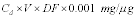 Where: Cd
= measured conc. formaldehyde, µg/ml V = total volume of stack
sample, ml DF = dilution factor
Where: Cd
= measured conc. formaldehyde, µg/ml V = total volume of stack
sample, ml DF = dilution factor
12.1.2 To determine the total formaldehyde in mg, use the following equation if biocide was used:
Total mg formaldehyde=
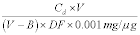 Where: Cd
= measured conc. formaldehyde, µg/ml V = total volume of stack
sample, ml B = total volume of biocide added to sample, ml DF =
dilution factor
Where: Cd
= measured conc. formaldehyde, µg/ml V = total volume of stack
sample, ml B = total volume of biocide added to sample, ml DF =
dilution factor
12.2 Formaldehyde concentration (mg/m 3) in stack gas. Determine the formaldehyde concentration (mg/m 3) in the stack gas using the following equation: Formaldehyde concentration (mg/m 3) =
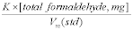 Where: K
= 35.31 cu ft/m 3 for Vm (std) in English units, or K = 1.00 m 3/m
3 for Vm (std) in metric units Vm (std) = volume of gas sample
measured by a dry gas meter, corrected to standard conditions, dscm
(dscf)
Where: K
= 35.31 cu ft/m 3 for Vm (std) in English units, or K = 1.00 m 3/m
3 for Vm (std) in metric units Vm (std) = volume of gas sample
measured by a dry gas meter, corrected to standard conditions, dscm
(dscf)
12.3 Average dry gas meter temperature and average orifice pressure drop are obtained from the data sheet.
12.4 Dry Gas Volume: Calculate Vm (std) and adjust for leakage, if necessary, using the equation in Section 6.3 of EPA Method 5, 40 CFR part 60, appendix A.
12.5 Volume of Water Vapor and Moisture Content: Calculated the volume of water vapor and moisture content from equations 5-2 and 5-3 of EPA Method 5.
13.0 Method PerformanceThe precision of this method is estimated to be better than ±5 percent, expressed as ±the percent relative standard deviation.
14.0 Pollution Prevention [Reserved] 15.0 Waste Management [Reserved] 16.0 References R.R. Miksch, et al., Analytical Chemistry, November 1981, 53 pp. 2118-2123. J.F. Walker, Formaldehyde, Third Edition, 1964. US EPA 40 CFR, part 60, Appendix A, Test Methods 1-5 Method 318 - Extractive FTIR Method for the Measurement of Emissions From the Mineral Wool and Wool Fiberglass Industries 1.0 Scope and ApplicationThis method has been validated and approved for mineral wool and wool fiberglass sources. This method may not be applied to other source categories without validation and approval by the Administrator according to the procedures in Test Method 301, 40 CFR part 63, appendix A. For sources seeking to apply FTIR to other source categories, Test Method 320 (40 CFR part 63, appendix A) may be utilized.
1.1 Scope. The analytes measured by this method and their CAS numbers are:
Carbon Monoxide 630-08-0 Carbonyl Sulfide 463-58-1 Formaldehyde 50-00-0 Methanol 1455-13-6 Phenol 108-95-21.2 Applicability
1.2.1 This method is applicable for the determination of formaldehyde, phenol, methanol, carbonyl sulfide (COS) and carbon monoxide (CO) concentrations in controlled and uncontrolled emissions from manufacturing processes using phenolic resins. The compounds are analyzed in the mid-infrared spectral region (about 400 to 4000 cm−1 or 25 to 2.5 µm). Suggested analytical regions are given below (Table 1). Slight deviations from these recommended regions may be necessary due to variations in moisture content and ammonia concentration from source to source.
Table 1 - Example Analytical Regions
| Compound | Analytical region (cm−1) FLm − FUm |
Potential interferants |
|---|---|---|
| Formaldehyde | 2840.93−2679.83 | Water, Methane. |
| Phenol | 1231.32−1131.47 | Water, Ammonia, Methane. |
| Methanol | 1041.56−1019.95 | Water, Ammonia. |
| COS a | 2028.4−2091.9 | Water, CO2 CO. |
| CO a | 2092.1−2191.8 | Water, CO2, COS. |
a Suggested analytical regions assume about 15 percent moisture and CO2, and that COS and CO have about the same absorbance (in the range of 10 to 50 ppm). If CO and COS are hundreds of ppm or higher, then CO2 and moisture interference is reduced. If CO or COS is present at high concentration and the other at low concentration, then a shorter cell pathlength may be necessary to measure the high concentration component.
1.3 Method Range and Sensitivity
1.3.1 The analytical range is a function of instrumental design and composition of the gas stream. Theoretical detection limits depend, in part, on (a) the absorption coefficient of the compound in the analytical frequency region, (b) the spectral resolution, (c) interferometer sampling time, (d) detector sensitivity and response, and (e) absorption pathlength.
1.3.2 Practically, there is no upper limit to the range. The practical lower detection limit is usually higher than the theoretical value, and depends on (a) moisture content of the flue gas, (b) presence of interferants, and (c) losses in the sampling system. In general, a 22 meter pathlength cell in a suitable sampling system can achieve practical detection limits of 1.5 ppm for three compounds (formaldehyde, phenol, and methanol) at moisture levels up to 15 percent by volume. Sources with uncontrolled emissions of CO and COS may require a 4 meter pathlength cell due to high concentration levels. For these two compounds, make sure absorbance of highest concentration component is <1.0.
1.4 Data Quality Objectives
1.4.1 In designing or configuring the system, the analyst first sets the data quality objectives, i.e., the desired lower detection limit (DLi) and the desired analytical uncertainty (AUi) for each compound. The instrumental parameters (factors b, c, d, and e in Section 1.3.1) are then chosen to meet these requirements, using Appendix D of the FTIR Protocol. 1.4.2 Data quality for each application is determined, in part, by measuring the RMS (Root Mean Square) noise level in each analytical spectral region (Appendix C of the FTIR Protocol). The RMS noise is defined as the RMSD (Root Mean Square Deviation) of the absorbance values in an analytical region from the mean absorbance value of the region. Appendix D of the FTIR Protocol defines the MAUim (minimum analyte uncertainty of the i th analyte in the m th analytical region). The MAU is the minimum analyte concentration for which the analytical uncertainty limit (AUi) can be maintained: if the measured analyte concentration is less than MAUi, then data quality is unacceptable. Table 2 gives some example DL and AU values along with calculated areas and MAU values using the protocol procedures.Table 2 - Example Pre-Test Protocol Calculations
| Protocol value | Form | Phenol | Methanol | Protocol appendix |
|---|---|---|---|---|
| Reference concentration a (ppm-meters)/K | 3.016 | 3.017 | 5.064 | |
| Reference Band Area | 8.2544 | 16.6417 | 4.9416 | B |
| DL (ppm-meters)/K | 0.1117 | 0.1117 | 0.1117 | B |
| AU | 0.2 | 0.2 | 0.2 | B |
| CL | 0.02234 | 0.02234 | 0.02234 | B |
| FL | 2679.83 | 1131.47 | 1019.95 | B |
| FU | 2840.93 | 1231.32 | 1041.56 | B |
| FC | 2760.38 | 1181.395 | 1030.755 | B |
| AAI (ppm-meters)/K | 0.18440 | 0.01201 | 0.00132 | B |
| RMSD | 2.28E-03 | 1.21E-03 | 1.07E-03 | C |
| MAU (ppm-meters)/K | 4.45E-02 | 7.26E-03 | 4.68E-03 | D |
| MAU (ppm at 22) | 0.0797 | 0.0130 | 0.0084 | D |
a Concentration units are: ppm concentration of the reference sample (ASC), times the path length of the FTIR cell used when the reference spectrum was measured (meters), divided by the absolute temperature of the reference sample in Kelvin (K), or (ppm-meters)/K.
2.1 Principle
2.1.1 Molecules are composed of chemically bonded atoms, which are in constant motion. The atomic motions result in bond deformations (bond stretching and bond-angle bending). The number of fundamental (or independent) vibrational motions depends on the number of atoms (N) in the molecule. At typical testing temperatures, most molecules are in the ground-state vibrational state for most of their fundamental vibrational motions. A molecule can undergo a transition from its ground state (for a particular vibration) to the first excited state by absorbing a quantum of light at a frequency characteristic of the molecule and the molecular motion. Molecules also undergo rotational transitions by absorbing energies in the far-infrared or microwave spectral regions. Rotational transition absorbencies are superimposed on the vibrational absorbencies to give a characteristic shape to each rotational-vibrational absorbance “band.”
2.1.2 Most molecules exhibit more than one absorbance band in several frequency regions to produce an infrared spectrum (a characteristic pattern of bands or a “fingerprint”) that is unique to each molecule. The infrared spectrum of a molecule depends on its structure (bond lengths, bond angles, bond strengths, and atomic masses). Even small differences in structure can produce significantly different spectra.
2.1.3 Spectral band intensities vary with the concentration of the absorbing compound. Within constraints, the relationship between absorbance and sample concentration is linear. Sample spectra are compared to reference spectra to determine the species and their concentrations.
2.2 Sampling and Analysis
2.2.1 Flue gas is continuously extracted from the source, and the gas or a portion of the gas is conveyed to the FTIR gas cell, where a spectrum of the flue gas is recorded. Absorbance band intensities are related to sample concentrations by Beer's Law.
 Where: An
= absorbance of the i th component at the given frequency, ν. a =
absorption coefficient of the i th component at the frequency, ν. b
= path length of the cell. c = concentration of the i th compound
in the sample at frequency ν.
Where: An
= absorbance of the i th component at the given frequency, ν. a =
absorption coefficient of the i th component at the frequency, ν. b
= path length of the cell. c = concentration of the i th compound
in the sample at frequency ν.
2.2.2 After identifying a compound from the infrared spectrum, its concentration is determined by comparing band intensities in the sample spectrum to band intensities in “reference spectra” of the formaldehyde, phenol, methanol, COS and CO. These reference spectra are available in a permanent soft copy from the EPA spectral library on the EMTIC bulletin board. The source may also prepare reference spectra according to Section 4.5 of the FTIR Protocol.
Note:Reference spectra not prepared according to the FTIR Protocol are not acceptable for use in this test method. Documentation detailing the FTIR Protocol steps used in preparing any non-EPA reference spectra shall be included in each test report submitted by the source.
2.3 Operator Requirements. The analyst must have some knowledge of source sampling and of infrared spectral patterns to operate the sampling system and to choose a suitable instrument configuration. The analyst should also understand FTIR instrument operation well enough to choose an instrument configuration consistent with the data quality objectives.
3.0 DefinitionsSee Appendix A of the FTIR Protocol.
4.0 Interferences4.1 Analytical (or Spectral) Interferences. Water vapor. High concentrations of ammonia (hundreds of ppm) may interfere with the analysis of low concentrations of methanol (1 to 5 ppm). For CO, carbon dioxide and water may be interferants. In cases where COS levels are low relative to CO levels, CO and water may be interferants.
4.2 Sampling System Interferences. Water, if it condenses, and ammonia, which reacts with formaldehyde.
5.0 Safety5.1 Formaldehyde is a suspected carcinogen; therefore, exposure to this compound must be limited. Proper monitoring and safety precautions must be practiced in any atmosphere with potentially high concentrations of CO.
5.2 This method may involve sampling at locations having high positive or negative pressures, high temperatures, elevated heights, high concentrations of hazardous or toxic pollutants, or other diverse sampling conditions. It is the responsibility of the tester(s) to ensure proper safety and health practices, and to determine the applicability of regulatory limitations before performing this test method.
6.0 Equipment and SuppliesThe equipment and supplies are based on the schematic of a sampling train shown in Figure 1. Either the evacuated or purged sampling technique may be used with this sampling train. Alternatives may be used, provided that the data quality objectives of this method are met.
6.1 Sampling Probe. Glass, stainless steel, or other appropriate material of sufficient length and physical integrity to sustain heating, prevent adsorption of analytes, and to reach gas sampling point.
6.2 Particulate Filters. A glass wool plug (optional) inserted at the probe tip (for large particulate removal) and a filter rated at 1-micron (e.g., Balston TM) for fine particulate removal, placed immediately after the heated probe.
6.3 Sampling Line/Heating System. Heated (maintained at 250 ±25 degrees F) stainless steel, Teflon TM, or other inert material that does not adsorb the analytes, to transport the sample to analytical system.
6.4 Stainless Steel Tubing. Type 316, e.g., 3/8 in. diameter, and appropriate length for heated connections.
6.5 Gas Regulators. Appropriate for individual gas cylinders.
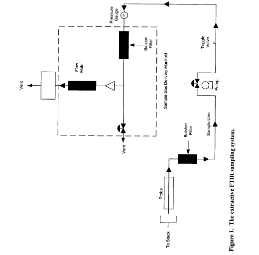
6.6 Teflon TM Tubing. Diameter (e.g., 3/8 in.) and length suitable to connect cylinder regulators.
6.7 Sample Pump. A leak-free pump (e.g., KNF TM), with by-pass valve, capable of pulling sample through entire sampling system at a rate of about 10 to 20 L/min. If placed before the analytical system, heat the pump and use a pump fabricated from materials non-reactive to the target pollutants. If the pump is located after the instrument, systematically record the sample pressure in the gas cell.
6.8 Gas Sample Manifold. A heated manifold that diverts part of the sample stream to the analyzer, and the rest to the by-pass discharge vent or other analytical instrumentation.
6.9 Rotameter. A calibrated 0 to 20 L/min range rotameter.
6.10 FTIR Analytical System. Spectrometer and detector, capable of measuring formaldehyde, phenol, methanol, COS and CO to the predetermined minimum detectable level. The system shall include a personal computer with compatible software that provides real-time updates of the spectral profile during sample collection and spectral collection.
6.11 FTIR Cell Pump. Required for the evacuated sampling technique, capable of evacuating the FTIR cell volume within 2 minutes. The FTIR cell pump should allow the operator to obtain at least 8 sample spectra in 1 hour.
6.12 Absolute Pressure Gauge. Heatable and capable of measuring pressure from 0 to 1000 mmHg to within ±2.5 mmHg (e.g., Baratron TM).
6.13 Temperature Gauge. Capable of measuring the cell temperature to within ±2 °C.
7.0 Reagents and Standards7.1 Ethylene (Calibration Transfer Standard). Obtain NIST traceable (or Protocol) cylinder gas.
7.2 Nitrogen. Ultra high purity (UHP) grade.
7.3 Reference Spectra. Obtain reference spectra for the target pollutants at concentrations that bracket (in ppm-meter/K) the emission source levels. Also, obtain reference spectra for SF6 and ethylene. Suitable concentrations are 0.0112 to 0.112 (ppm-meter)/K for SF6 and 5.61 (ppm-meter)/K or less for ethylene. The reference spectra shall meet the criteria for acceptance outlined in Section 2.2.2. The optical density (ppm-meters/K) of the reference spectrum must match the optical density of the sample spectrum within (less than) 25 percent.
8.0 Sample Collection, Preservation, and StorageSampling should be performed in the following sequence: Collect background, collect CTS spectrum, collect samples, collect post-test CTS spectrum, verify that two copies of all data were stored on separate computer media.
8.1 Pretest Preparations and Evaluations. Using the procedure in Section 4.0 of the FTIR Protocol, determine the optimum sampling system configuration for sampling the target pollutants. Table 2 gives some example values for AU, DL, and MAU. Based on a study (Reference 1), an FTIR system using 1 cm−1 resolution, 22 meter path length, and a broad band MCT detector was suitable for meeting the requirements in Table 2. Other factors that must be determined are:
a. Test requirements: AUi, CMAXi, DLi, OFUi, and tAN for each.
b. Interferants: See Table 1.
c. Sampling system: LS′, Pmin, PS′, TS′, tSS, VSS; fractional error, MIL.
d. Analytical regions: 1 through Nm, FLm, FCm, and FUm, plus interferants, FFUm, FFLm, wavenumber range FNU to FNL. See Tables 1 and 2.
8.1.1 If necessary, sample and acquire an initial spectrum. Then determine the proper operational pathlength of the instrument to obtain non-saturated absorbances of the target analytes.
8.1.2 Set up the sampling train as shown in Figure 1.
8.2 Sampling System Leak-check. Leak-check from the probe tip to pump outlet as follows: Connect a 0- to 250-mL/min rate meter (rotameter or bubble meter) to the outlet of the pump. Close off the inlet to the probe, and note the leakage rate. The leakage rate shall be ≤200 mL/min.
8.3 Analytical System Leak-check.
8.3.1 For the evacuated sample technique, close the valve to the FTIR cell, and evacuate the absorption cell to the minimum absolute pressure Pmin. Close the valve to the pump, and determine the change in pressure ΔPv after 2 minutes.
8.3.2 For both the evacuated sample and purging techniques, pressurize the system to about 100 mmHg above atmospheric pressure. Isolate the pump and determine the change in pressure ΔPp after 2 minutes.
8.3.3 Measure the barometric pressure, Pb in mmHg.
8.3.4 Determine the percent leak volume %VL for the signal integration time tSS and for ΔPmax, i.e., the larger of ΔPv or ΔPp, as follows:
 Where: 50
= 100% divided by the leak-check time of 2 minutes.
Where: 50
= 100% divided by the leak-check time of 2 minutes.
8.3.5 Leak volumes in excess of 4 percent of the sample system volume VSS are unacceptable.
8.4 Background Spectrum. Evacuate the gas cell to ≤5 mmHg, and fill with dry nitrogen gas to ambient pressure. Verify that no significant amounts of absorbing species (for example water vapor and CO2) are present. Collect a background spectrum, using a signal averaging period equal to or greater than the averaging period for the sample spectra. Assign a unique file name to the background spectrum. Store the spectra of the background interferogram and processed single-beam background spectrum on two separate computer media (one is used as the back-up). If continuous sampling will be used during sample collection, collect the background spectrum with nitrogen gas flowing through the cell at the same pressure and temperature as will be used during sampling.
8.5 Pre-Test Calibration Transfer Standard. Evacuate the gas cell to ≤5 mmHg absolute pressure, and fill the FTIR cell to atmospheric pressure with the CTS gas. Or, purge the cell with 10 cell volumes of CTS gas. Record the spectrum. If continuous sampling will be used during sample collection, collect the CTS spectrum with CTS gas flowing through the cell at the same pressure and temperature as will be used during sampling.
8.6 Samples
8.6.1 Evacuated Samples. Evacuate the absorbance cell to ≤5 mmHg absolute pressure. Fill the cell with flue gas to ambient pressure and record the spectrum. Before taking the next sample, evacuate the cell until no further evidence of absorption exists. Repeat this procedure to collect at least 8 separate spectra (samples) in 1 hour.
8.6.2 Purge Sampling. Purge the FTIR cell with 10 cell volumes of flue gas and at least for about 10 minutes. Discontinue the gas cell purge, isolate the cell, and record the sample spectrum and the pressure. Before taking the next sample, purge the cell with 10 cell volumes of flue gas.
8.6.3 Continuous Sampling. Spectra can be collected continuously while the FTIR cell is being purged. The sample integration time, tss, the sample flow rate through the FTIR gas cell, and the total run time must be chosen so that the collected data consist of at least 10 spectra with each spectrum being of a separate cell volume of flue gas. More spectra can be collected over the run time and the total run time (and number of spectra) can be extended as well.
8.7 Sampling QA, Data Storage and Reporting
8.7.1 Sample integration times should be sufficient to achieve the required signal-to-noise ratios. Obtain an absorbance spectrum by filling the cell with nitrogen. Measure the RMSD in each analytical region in this absorbance spectrum. Verify that the number of scans is sufficient to achieve the target MAU (Table 2).
8.7.2 Identify all sample spectra with unique file names.
8.7.3 Store on two separate computer media a copy of sample interferograms and processed spectra. The data shall be available to the Administrator on request for the length of time specified in the applicable regulation.
8.7.4 For each sample spectrum, document the sampling conditions, the sampling time (while the cell was being filled), the time the spectrum was recorded, the instrumental conditions (path length, temperature, pressure, resolution, integration time), and the spectral file name. Keep a hard copy of these data sheets.
8.8 Signal Transmittance. While sampling, monitor the signal transmittance through the instrumental system. If signal transmittance (relative to the background) drops below 95 percent in any spectral region where the sample does not absorb infrared energy, obtain a new background spectrum.
8.9 Post-run CTS. After each sampling run, record another CTS spectrum.
8.10 Post-test QA
8.10.1 Inspect the sample spectra immediately after the run to verify that the gas matrix composition was close to the expected (assumed) gas matrix.
8.10.2 Verify that the sampling and instrumental parameters were appropriate for the conditions encountered. For example, if the moisture is much greater than anticipated, it will be necessary to use a shorter path length or dilute the sample.
8.10.3 Compare the pre and post-run CTS spectra. They shall agree to within −5 percent. See FTIR Protocol, Appendix E.
9.0 Quality ControlFollow the quality assurance procedures in the method, including the analysis of pre and post-run calibration transfer standards (Sections 8.5 and 8.9) and the post-test quality assurance procedures in Section 8.10.
10.0 Calibration and Standardization10.1 Signal-to-Noise Ratio (S/N). The S/N shall be sufficient to meet the MAU in each analytical region.
10.2 Absorbance Pathlength. Verify the absorbance path length by comparing CTS spectra to reference spectra of the calibration gas(es). See FTIR Protocol, Appendix E.
10.3 Instrument Resolution. Measure the line width of appropriate CTS band(s) and compare to reference CTS spectra to verify instrumental resolution.
10.4 Apodization Function. Choose appropriate apodization function. Determine any appropriate mathematical transformations that are required to correct instrumental errors by measuring the CTS. Any mathematical transformations must be documented and reproducible.
10.5 FTIR Cell Volume. Evacuate the cell to ≤5 mmHg. Measure the initial absolute temperature (Ti) and absolute pressure (Pi). Connect a wet test meter (or a calibrated dry gas meter), and slowly draw room air into the cell. Measure the meter volume (Vm), meter absolute temperature (Tm), and meter absolute pressure (Pm), and the cell final absolute temperature (Tf) and absolute pressure (Pf). Calculate the FTIR cell volume Vss, including that of the connecting tubing, as follows:
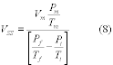 As an
alternative to the wet test meter/calibrated dry gas meter
procedure, measure the inside dimensions of the cell cylinder and
calculate its volume. 11.0 Procedure
As an
alternative to the wet test meter/calibrated dry gas meter
procedure, measure the inside dimensions of the cell cylinder and
calculate its volume. 11.0 Procedure
Refer to Sections 4.6-4.11, Sections 5, 6, and 7, and the appendices of the FTIR Protocol.
12.0 Data Analysis and Calculationsa. Data analysis is performed using appropriate reference spectra whose concentrations can be verified using CTS spectra. Various analytical programs are available to relate sample absorbance to a concentration standard. Calculated concentrations should be verified by analyzing spectral baselines after mathematically subtracting scaled reference spectra from the sample spectra. A full description of the data analysis and calculations may be found in the FTIR Protocol (Sections 4.0, 5.0, 6.0 and appendices).
b. Correct the calculated concentrations in sample spectra for differences in absorption pathlength between the reference and sample spectra by:
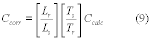 Where:
Ccorr = The pathlength corrected concentration. Ccalc = The initial
calculated concentration (output of the Multicomp program designed
for the compound). Lr = The pathlength associated with the
reference spectra. Ls = The pathlength associated with the sample
spectra. Ts = The absolute temperature (K) of the sample gas. Tr =
The absolute gas temperature (K) at which reference spectra were
recorded. 13.0 Reporting and Recordkeeping
Where:
Ccorr = The pathlength corrected concentration. Ccalc = The initial
calculated concentration (output of the Multicomp program designed
for the compound). Lr = The pathlength associated with the
reference spectra. Ls = The pathlength associated with the sample
spectra. Ts = The absolute temperature (K) of the sample gas. Tr =
The absolute gas temperature (K) at which reference spectra were
recorded. 13.0 Reporting and Recordkeeping
All interferograms used in determining source concentration shall be stored for the period of time required in the applicable regulation. The Administrator has the option of requesting the interferograms recorded during the test in electronic form as part of the test report.
14.0 Method PerformanceRefer to the FTIR Protocol.
15.0 Pollution Prevention [Reserved] 16.0 Waste ManagementLaboratory standards prepared from the formaldehyde and phenol are handled according to the instructions in the materials safety data sheets (MSDS).
17.0 References(1) “Field Validation Test Using Fourier Transform Infrared (FTIR) Spectrometry To Measure Formaldehyde, Phenol and Methanol at a Wool Fiberglass Production Facility.” Draft. U.S. Environmental Protection Agency Report, Entropy, Inc., EPA Contract No. 68D20163, Work Assignment I-32, December 1994 (docket item II-A-13).
(2) “Method 301 - Field Validation of Pollutant Measurement Methods from Various Waste Media,” 40 CFR part 63, appendix A.
Method 319 - Determination of Filtration Efficiency for Paint Overspray Arrestors 1.0 Scope and Application1.1 This method applies to the determination of the initial, particle size dependent, filtration efficiency for paint arrestors over the particle diameter range from 0.3 to 10 µm. The method applies to single and multiple stage paint arrestors or paint arrestor media. The method is applicable to efficiency determinations from 0 to 99 percent. Two test aerosols are used - one liquid phase and one solid phase. Oleic acid, a low-volatility liquid (CAS Number 112-80-1), is used to simulate the behavior of wet paint overspray. The solid-phase aerosol is potassium chloride salt (KCl, CAS Number 7447-40-7) and is used to simulate the behavior of a dry overspray. The method is limited to determination of the initial, clean filtration efficiency of the arrestor. Changes in efficiency (either increase or decrease) due to the accumulation of paint overspray on and within the arrestor are not evaluated.
1.2 Efficiency is defined as 1 - Penetration (e.g., 70 percent efficiency is equal to 0.30 penetration). Penetration is based on the ratio of the downstream particle concentration to the upstream concentration. It is often more useful, from a mathematical or statistical point of view, to discuss the upstream and downstream counts in terms of penetration rather than the derived efficiency value. Thus, this document uses both penetration and efficiency as appropriate.
1.3 For a paint arrestor system or subsystem which has been tested by this method, adding additional filtration devices to the system or subsystem shall be assumed to result in an efficiency of at least that of the original system without the requirement for additional testing. (For example, if the final stage of a three-stage paint arrestor system has been tested by itself, then the addition of the other two stages shall be assumed to maintain, as a minimum, the filtration efficiency provided by the final stage alone. Thus, in this example, if the final stage has been shown to meet the filtration requirements of Table 1 of § 63.745 of subpart GG, then the final stage in combination with any additional paint arrestor stages also passes the filtration requirements.)
2.0 Summary of Method2.1 This method applies to the determination of the fractional (i.e., particle-size dependent) aerosol penetration of several types of paint arrestors. Fractional penetration is computed from aerosol concentrations measured upstream and downstream of an arrestor installed in a laboratory test rig. The aerosol concentrations upstream and downstream of the arrestors are measured with an aerosol analyzer that simultaneously counts and sizes the particles in the aerosol stream. The aerosol analyzer covers the particle diameter size range from 0.3 to 10 µm in a minimum of 12 contiguous sizing channels. Each sizing channel covers a narrow range of particle diameters. For example, Channel 1 may cover from 0.3 to 0.4 µm, Channel 2 from 0.4 to 0.5 µm, * * * By taking the ratio of the downstream to upstream counts on a channel by channel basis, the penetration is computed for each of the sizing channels.
2.2 The upstream and downstream aerosol measurements are made while injecting the test aerosol into the air stream upstream of the arrestor (ambient aerosol is removed with HEPA filters on the inlet of the test rig). This test aerosol spans the particle size range from 0.3 to 10 µm and provides sufficient upstream concentration in each of the optical particle counter (OPC) sizing channels to allow accurate calculation of penetration, down to penetrations of approximately 0.01 (i.e., 1 percent penetration; 99 percent efficiency). Results are presented as a graph and a data table showing the aerodynamic particle diameter and the corresponding fractional efficiency.
3.0 DefinitionsAerodynamic Diameter - diameter of a unit density sphere having the same aerodynamic properties as the particle in question.
Efficiency is defined as equal to 1 - Penetration.
Optical Particle Counter (OPC) - an instrument that counts particles by size using light scattering. An OPC gives particle diameters based on size, index of refraction, and shape.
Penetration - the fraction of the aerosol that penetrates the filter at a given particle diameter. Penetration equals the downstream concentration divided by the upstream concentration.
4.0 Interferences4.1 The influence of the known interferences (particle losses) are negated by correction of the data using blanks.
5.0 Safety5.1 There are no specific safety precautions for this method above those of good laboratory practice. This standard does not purport to address all of the safety problems, if any, associated with its use. It is the responsibility of the user of this method to establish appropriate safety and health practices and determine the applicability of regulatory limitations prior to use.
6.0 Equipment and Supplies6.1 Test Facility. A schematic diagram of a test duct used in the development of the method is shown in Figure 319-1.
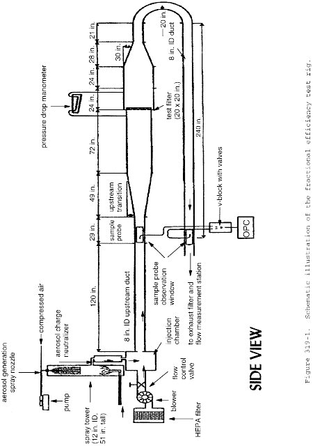
6.1.1 The test section, paint spray section, and attached transitions are constructed of stainless and galvanized steel. The upstream and downstream ducting is 20 cm diameter polyvinyl chloride (PVC). The upstream transition provides a 7 ° angle of expansion to provide a uniform air flow distribution to the paint arrestors. Aerosol concentration is measured upstream and downstream of the test section to obtain the challenge and penetrating aerosol concentrations, respectively. Because the downstream ducting runs back under the test section, the challenge and penetrating aerosol taps are located physically near each other, thereby facilitating aerosol sampling and reducing sample-line length. The inlet nozzles of the upstream and downstream aerosol probes are designed to yield isokinetic sampling conditions.
6.1.2 The configuration and dimensions of the test duct can deviate from those of Figure 319-1 provided that the following key elements are maintained: the test duct must meet the criteria specified in Table 319-1; the inlet air is HEPA filtered; the blower is on the upstream side of the duct thereby creating a positive pressure in the duct relative to the surrounding room; the challenge air has a temperature between 50 ° and 100 °F and a relative humidity of less than 65 percent; the angle of the upstream transition (if used) to the paint arrestor must not exceed 7 °; the angle of the downstream transition (if used) from the paint arrestor must not exceed 30 °; the test duct must provide a means for mixing the challenge aerosol with the upstream flow (in lieu of any mixing device, a duct length of 15 duct diameters fulfills this requirement); the test duct must provide a means for mixing any penetrating aerosol with the downstream flow (in lieu of any mixing device, a duct length of 15 duct diameters fulfills this requirement); the test section must provide a secure and leak-free mounting for single and multiple stage arrestors; and the test duct may utilize a 180 ° bend in the downstream duct.
Table 319-1 - QC Control Limits
| Frequency and description | Control limits | |
|---|---|---|
| OPC zero count | Each Test. OPC samples HEPA-filtered air | <50 counts per minute. |
| OPC sizing accuracy check | Daily. Sample aerosolized PSL spheres | Peak of distribution should be in correct OPC channel. |
| Minimum counts per channel for challenge aerosol | Each Test | Minimum total of 500 particle counts per channel. |
| Maximum particle concentration | Each Test. Needed to ensure OPC is not overloaded | <10% of manufacturer's claimed upper limit corresponding to a 10% count error. |
| Standard Deviation of Penetration | Computed for each test based on the CV of the upstream and downstream counts | <0.10 for 0.3 to 3 µm
diameter. <0.30 for >3 µm diameter. |
| 0% Penetration | Monthly | <0.01. |
| 100% Penetration - KCl | Triplicate tests performed immediately before, during, or after triplicate arrestor tests | 0.3 to 1 µm: 0.90 to 1.10. 1 to 3 µm: 0.75 to 1.25. 3 to 10 µm: 0.50 to 1.50. |
| 100% Penetration - Oleic Acid | Triplicate tests performed immediately before, during, or after triplicate arrestor tests | 0.3 to 1 µm: 0.90 to 1.10. 1 to 3 µm: 0.75 to 1.25. 3 to 10 µm: 0.50 to 1.50. |
6.2 Aerosol Generator. The aerosol generator is used to produce a stable aerosol covering the particle size range from 0.3 to 10 µm diameter. The generator used in the development of this method consists of an air atomizing nozzle positioned at the top of a 0.30-m (12-in.) diameter, 1.3-m (51-in.) tall, acrylic, transparent, spray tower. This tower allows larger sized particles, which would otherwise foul the test duct and sample lines, to fall out of the aerosol. It also adds drying air to ensure that the KCl droplets dry to solid salt particles. After generation, the aerosol passes through an aerosol neutralizer (Kr85 radioactive source) to neutralize any electrostatic charge on the aerosol (electrostatic charge is an unavoidable consequence of most aerosol generation methods). To improve the mixing of the aerosol with the air stream, the aerosol is injected counter to the airflow. Generators of other designs may be used, but they must produce a stable aerosol concentration over the 0.3 to 10 µm diameter size range; provide a means of ensuring the complete drying of the KCl aerosol; and utilize a charge neutralizer to neutralize any electrostatic charge on the aerosol. The resultant challenge aerosol must meet the minimum count per channel and maximum concentration criteria of Table 319-1.
6.3 Installation of Paint Arrestor. The paint arrestor is to be installed in the test duct in a manner that precludes air bypassing the arrestor. Since arrestor media are often sold unmounted, a mounting frame may be used to provide back support for the media in addition to sealing it into the duct. The mounting frame for 20 in. × 20 in. arrestors will have minimum open internal dimensions of 18 in. square. Mounting frames for 24 in. × 24 in. arrestors will have minimum open internal dimensions of 22 in. square. The open internal dimensions of the mounting frame shall not be less than 75 percent of the approach duct dimensions.
6.4 Optical Particle Counter. The upstream and downstream aerosol concentrations are measured with a high-resolution optical particle counter (OPC). To ensure comparability of test results, the OPC shall utilize an optical design based on wide-angle light scattering and provided a minimum of 12 contiguous particle sizing channels from 0.3 to 10 µm diameter (based on response to PSL) where, for each channel, the ratio of the diameter corresponding to the upper channel bound to the lower channel bound must not exceed 1.5.
6.5 Aerosol Sampling System. The upstream and downstream sample lines must be made of rigid electrically-grounded metallic tubing having a smooth inside surface, and they must be rigidly secured to prevent movement during testing. The upstream and downstream sample lines are to be nominally identical in geometry. The use of a short length (100 mm maximum) of straight flexible tubing to make the final connection to the OPC is acceptable. The inlet nozzles of the upstream and downstream probes must be sharp-edged and of appropriate entrance diameter to maintain isokinetic sampling within 20 percent of the air velocity.
6.5.1 The sampling system may be designed to acquire the upstream and downstream samples using (a) sequential upstream-downstream sampling with a single OPC, (b) simultaneous upstream and downstream sampling with two OPC's, or (c) sequential upstream-downstream sampling with two OPC's.
6.5.2 When two particle counters are used to acquire the upstream and downstream counts, they must be closely matched in flowrate and optical design.
6.6 Airflow Monitor. The volumetric airflow through the system shall be measured with a calibrated orifice plate, flow nozzle, or laminar flow element. The measurement device must have an accuracy of 5 percent or better.
7.0 Reagents and Standards7.1 The liquid test aerosol is reagent grade, 98 percent pure, oleic acid (Table 319-2). The solid test aerosol is KCl aerosolized from a solution of KCl in water. In addition to the test aerosol, a calibration aerosol of monodisperse polystyrene latex (PSL) spheres is used to verify the calibration of the OPC.
Table 319-2 - Properties of the Test and Calibration Aerosols
| Refractive index | Density, g/cm 3 |
Shape | |
|---|---|---|---|
| Oleic Acid (liquid-phase challenge aerosol) | 1.46 nonabsorbing | 0.89 | Spherical. |
| KCl (solid-phase challenge aerosol) | 1.49 | 1.98 | Cubic or agglomerated cubes. |
| PSL (calibration aerosol) | 1.59 nonabsorbing | 1.05 | Spherical. |
8.1 In this test, all sampling occurs in real-time, thus no samples are collected that require preservation or storage during the test. The paint arrestors are shipped and stored to avoid structural damage or soiling. Each arrestor may be shipped in its original box from the manufacturer or similar cardboard box. Arrestors are stored at the test site in a location that keeps them clean and dry. Each arrestor is clearly labeled for tracking purposes.
9.0 Quality Control9.1 Table 319-1 lists the QC control limits.
9.2 The standard deviation (σ) of the penetration (P) for a given test at each of the 15 OPC sizing channels is computed from the coefficient of variation (CV, the standard deviation divided by the mean) of the upstream and downstream measurements as:
 For a
properly operating system, the standard deviation of the
penetration is <0.10 at particle diameters from 0.3 to 3 µm and
less than 0.30 at diameters >3 µm.
For a
properly operating system, the standard deviation of the
penetration is <0.10 at particle diameters from 0.3 to 3 µm and
less than 0.30 at diameters >3 µm.
9.3 Data Quality Objectives (DQO).
9.3.1 Fractional Penetration. From the triplicate tests of each paint arrestor model, the standard deviation for the penetration measurements at each particle size (i.e., for each sizing channel of the OPC) is computed as:
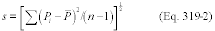 where Pi
represents an individual penetration measurement, and P the average
of the 3 (n = 3) individual measurements.
where Pi
represents an individual penetration measurement, and P the average
of the 3 (n = 3) individual measurements.
9.3.2 Bias of the fractional penetration values is determined from triplicate no-filter and HEPA filter tests. These tests determine the measurement bias at 100 percent penetration and 0 percent penetration, respectively.
9.3.3 PSL-Equivalent Light Scattering Diameter. The precision and bias of the OPC sizing determination are based on sampling a known diameter of PSL and noting whether the particle counts peak in the correct channel of the OPC. This is a pass/fail measurement with no calculations involved.
9.3.4 Airflow. The precision of the measurement must be within 5 percent of the set point.
10.0 Calibration and Standardization10.1 Optical Particle Counter. The OPC must have an up-to-date factory calibration. Check the OPC zero at the beginning and end of each test by sampling HEPA-filtered air. Verify the sizing accuracy on a daily basis (for days when tests are performed) with 1-size PSL spheres.
10.2 Airflow Measurement. Airflow measurement devices must have an accuracy of 5 percent or better. Manometers used in conjunction with the orifice plate must be inspected prior to use for proper level, zero, and mechanical integrity. Tubing connections to the manometer must be free from kinks and have secure connections.
10.3 Pressure Drop. Measure pressure drop across the paint arrestor with an inclined manometer readable to within 0.01 in. H2O. Prior to use, the level and zero of the manometer, and all tubing connections, must be inspected and adjusted as needed.
11.0 Procedure11.1 Filtration Efficiency. For both the oleic acid and KCl challenges, this procedure is performed in triplicate using a new arrestor for each test.
11.1.1 General Information and Test Duct Preparation
11.1.1.1 Use the “Test Run Sheet” form (Figure 319-2) to record the test information.
Run Sheet Part 1. General Information Date and Time: Test Operator: Test #: Paint Arrestor: Brand/Model Arrestor Assigned ID #Condition of arrestor (i.e., is there any damage? Must be new condition to proceed):
Manometer zero and level confirmed?
Part 2. Clean Efficiency Test Date and Time: Optical Particle Counter: 20 min. warm up Zero count (<50 counts/min) Daily PSL check PSL Diam: ___ µm File name for OPC data: Test Conditions: Air Flow: ___ Temp & RH: Temp ___ °F RH ___ % Atm. Pressure: ___in. Hg (From mercury barometer) Aerosol Generator: (record all operating parameters) Test Aerosol: (Oleic acid or KCl) Arrestor: Pressure drop: at start ___ in. H2O at end ___ in. H2OCondition of arrestor at end of test (note any physical deterioration):
Figure 319-2. Test Run SheetOther report formats which contain the same information are acceptable.
11.1.1.2 Record the date, time, test operator, Test #, paint arrestor brand/model and its assigned ID number. For tests with no arrestor, record none.
11.1.1.3 Ensure that the arrestor is undamaged and is in “new” condition.
11.1.1.4 Mount the arrestor in the appropriate frame. Inspect for any airflow leak paths.
11.1.1.5 Install frame-mounted arrestor in the test duct. Examine the installed arrestor to verify that it is sealed in the duct. For tests with no arrestor, install the empty frame.
11.1.1.6 Visually confirm the manometer zero and level. Adjust as needed.
11.1.2 Clean Efficiency Test.
11.1.2.1 Record the date and time upon beginning this section.
11.1.2.2 Optical Particle Counter.
11.1.2.2.1 General: Operate the OPC per the manufacturer's instructions allowing a minimum of 20 minutes warm up before making any measurements.
11.1.2.2.2 Overload: The OPC will yield inaccurate data if the aerosol concentration it is attempting to measure exceeds its operating limit. To ensure reliable measurements, the maximum aerosol concentration will not exceed 10 percent of the manufacturer's claimed upper concentration limit corresponding to a 10 percent count error. If this value is exceeded, reduce the aerosol concentration until the acceptable conditions are met.
11.1.2.2.3 Zero Count: Connect a HEPA capsule to the inlet of the OPC and obtain printouts for three samples (each a minimum of 1-minute each). Record maximum cumulative zero count. If the count rate exceeds 50 counts per minute, the OPC requires servicing before continuing.
11.1.2.2.4 PSL Check of OPC Calibration: Confirm the calibration of the OPC by sampling a known size PSL aerosol. Aerosolize the PSL using an appropriate nebulizer. Record whether the peak count is observed in the proper channel. If the peak is not seen in the appropriate channel, have the OPC recalibrated.
11.1.2.3 Test Conditions:
11.1.2.3.1 Airflow: The test airflow corresponds to a nominal face velocity of 120 FPM through the arrestor. For arrestors having nominal 20 in. × 20 in. face dimensions, this measurement corresponds to an airflow of 333 cfm. For arrestors having nominal face dimensions of 24 in. × 24 in., this measurement corresponds to an airflow of 480 cfm.
11.1.2.3.2 Temperature and Relative Humidity: The temperature and relative humidity of the challenge air stream will be measured to within an accuracy of ±2 °F and ±10 percent RH. To protect the probe from fouling, it may be removed during periods of aerosol generation.
11.1.2.3.3 Barometric Pressure: Use a mercury barometer. Record the atmospheric pressure.
11.1.2.4 Upstream and Downstream Background Counts.
11.1.2.4.1 With the arrestor installed in the test duct and the airflow set at the proper value, turn on the data acquisition computer and bring up the data acquisition program.
11.1.2.4.2 Set the OPC settings for the appropriate test sample duration with output for both printer and computer data collection.
11.1.2.4.3 Obtain one set of upstream-downstream background measurements.
11.1.2.4.4 After obtaining the upstream-downstream measurements, stop data acquisition.
11.1.2.5 Efficiency Measurements:
11.1.2.5.1 Record the arrestor pressure drop.
11.1.2.5.2 Turn on the Aerosol Generator. Begin aerosol generation and record the operating parameters.
11.1.2.5.3 Monitor the particle counts. Allow a minimum of 5 minutes for the generator to stabilize.
11.1.2.5.4 Confirm that the total particle count does not exceed the predetermined upper limit. Adjust generator as needed.
11.1.2.5.5 Confirm that a minimum of 50 particle counts are measured in the upstream sample in each of the OPC channels per sample. (A minimum of 50 counts per channel per sample will yield the required minimum 500 counts per channel total for the 10 upstream samples as specified in Table 319-1.) Adjust generator or sample time as needed.
11.1.2.5.6 If you are unable to obtain a stable concentration within the concentration limit and with the 50 count minimum per channel, adjust the aerosol generator.
11.1.2.5.7 When the counts are stable, perform repeated upstream-downstream sampling until 10 upstream-downstream measurements are obtained.
11.1.2.5.8 After collection of the 10 upstream-downstream samples, stop data acquisition and allow 2 more minutes for final purging of generator.
11.1.2.5.9 Obtain one additional set of upstream-downstream background samples.
11.1.2.5.10 After obtaining the upstream-downstream background samples, stop data acquisition.
11.1.2.5.11 Record the arrestor pressure drop.
11.1.2.5.12 Turn off blower.
11.1.2.5.13 Remove the paint arrestor assembly from the test duct. Note any signs of physical deterioration.
11.1.2.5.14 Remove the arrestor from the frame and place the arrestor in an appropriate storage bag.
11.2 Control Test: 100 Percent Penetration Test. A 100 percent penetration test must be performed immediately before each individual paint arrestor test using the same challenge aerosol substance (i.e., oleic acid or KCl) as to be used in the arrestor test. These tests are performed with no arrestor installed in the test housing. This test is a relatively stringent test of the adequacy of the overall duct, sampling, measurement, and aerosol generation system. The test is performed as a normal penetration test except the paint arrestor is not used. A perfect system would yield a measured penetration of 1 at all particle sizes. Deviations from 1 can occur due to particle losses in the duct, differences in the degree of aerosol uniformity (i.e., mixing) at the upstream and downstream probes, and differences in particle transport efficiency in the upstream and downstream sampling lines.
11.3 Control Test: 0 Percent Penetration. One 0 percent penetration test must be performed at least monthly during testing. The test is performed by using a HEPA filter rather than a paint arrestor. This test assesses the adequacy of the instrument response time and sample line lag.
12.0 Data Analysis and Calculations12.1 Analysis. The analytical procedures for the fractional penetration and flow velocity measurements are described in Section 11. Note that the primary measurements, those of the upstream and downstream aerosol concentrations, are performed with the OPC which acquires the sample and analyzes it in real time. Because all the test data are collected in real time, there are no analytical procedures performed subsequent to the actual test, only data analysis.
12.2 Calculations.
12.2.1 Penetration.
Nomenclature U = Upstream particle count D = Downstream particle count Ub = Upstream background count Db = Downstream background count P100 = 100 percent penetration value determined immediately prior to the arrestor test computed for each channel as: P = Penetration of
the arrestor corrected for P100 ρ= sample standard deviation CV =
coefficient of variation = ρ/mean E = Efficiency.
P = Penetration of
the arrestor corrected for P100 ρ= sample standard deviation CV =
coefficient of variation = ρ/mean E = Efficiency.
Overbar denotes arithmetic mean of quantity.
Analysis of each test involves the following quantities:
• P100 value for each sizing channel from the 100 percent penetration control test,
• 2 upstream background values,
• 2 downstream background values,
• 10 upstream values with aerosol generator on, and
• 10 downstream values with aerosol generator on.
Using the values associated with each sizing channel, the penetration associated with each particle-sizing channel is calculated as:
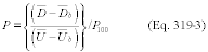
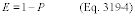
Most often, the background levels are small compared to the values when the aerosol generator is on.
12.3 The relationship between the physical diameter (DPhysical) as measured by the OPC to the aerodynamic diameter (DAero) is given by:
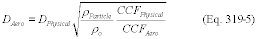 Where: pO
= unit density of 1 g/cm 3. pParticle = the density of the
particle, 0.89 g/cm 3 for oleic acid. CCFPhysical = the Cunningham
Correction Factor at DPhysical. CCFAero = the Cunningham Correction
Factor at D Aero.
Where: pO
= unit density of 1 g/cm 3. pParticle = the density of the
particle, 0.89 g/cm 3 for oleic acid. CCFPhysical = the Cunningham
Correction Factor at DPhysical. CCFAero = the Cunningham Correction
Factor at D Aero.
12.4 Presentation of Results. For a given arrestor, results will be presented for:
• Triplicate arrestor tests with the liquid-phase challenge aerosol,
• Triplicate arrestor tests with the solid-phase challenge aerosol,
• Triplicate 100 percent penetration tests with the liquid-phase challenge aerosol,
• Triplicate 100 percent penetration tests with the solid-phase challenge aerosol, and
• One 0 percent filter test (using either the liquid-phase or solid-phase aerosol and performed at least monthly).
12.4.1 Results for the paint arrestor test must be presented in both graphical and tabular form. The X-axis of the graph will be a logarithmic scale of aerodynamic diameter from 0.1 to 100 µm. The Y-axis will be efficiency (%) on a linear scale from 0 to 100. Plots for each individual run and a plot of the average of triplicate solid-phase and of the average triplicate liquid-phase tests must be prepared. All plots are to be based on point-to-point plotting (i.e., no curve fitting is to be used). The data are to be plotted based on the geometric mean diameter of each of the OPC's sizing channels.
12.4.2 Tabulated data from each test must be provided. The data must include the upper and lower diameter bound and geometric mean diameter of each of the OPC sizing channels, the background particle counts for each channel for each sample, the upstream particle counts for each channel for each sample, the downstream particle counts for each channel for each sample, the 100 percent penetration values computed for each channel, and the 0 percent penetration values computed for each channel.
13.0 Pollution Prevention13.1 The quantities of materials to be aerosolized should be prepared in accord with the amount needed for the current tests so as to prevent wasteful excess.
14.0 Waste Management14.1 Paint arrestors may be returned to originator, if requested, or disposed of with regular laboratory waste.
15.0 References1. Hanley, J.T., D.D. Smith and L. Cox. “Fractional Penetration of Paint Overspray Arrestors, Draft Final Report,” EPA Cooperative Agreement CR-817083-01-0, January 1994.
2. Hanley, J.T., D.D. Smith, and D.S. Ensor. “Define a Fractional Efficiency Test Method that is Compatible with Particulate Removal Air Cleaners Used in General Ventilation,” Final Report, 671-RP, American Society of Heating, Refrigerating, and Air-Conditioning Engineers, Inc., December 1993.
3. “Project Work and Quality Assurance Plan: Fractional Penetration of Paint Overspray Arrestors, Category II,” EPA Cooperative Agreement No. CR-817083, July 1994.
Test Method 320 - Measurement of Vapor Phase Organic and Inorganic Emissions by Extractive Fourier Transform Infrared (FTIR) Spectroscopy 1.0 IntroductionPersons unfamiliar with basic elements of FTIR spectroscopy should not attempt to use this method. This method describes sampling and analytical procedures for extractive emission measurements using Fourier transform infrared (FTIR) spectroscopy. Detailed analytical procedures for interpreting infrared spectra are described in the “Protocol for the Use of Extractive Fourier Transform Infrared (FTIR) Spectrometry in Analyses of Gaseous Emissions from Stationary Sources,” hereafter referred to as the “Protocol.” Definitions not given in this method are given in appendix A of the Protocol. References to specific sections in the Protocol are made throughout this Method. For additional information refer to references 1 and 2, and other EPA reports, which describe the use of FTIR spectrometry in specific field measurement applications and validation tests. The sampling procedure described here is extractive. Flue gas is extracted through a heated gas transport and handling system. For some sources, sample conditioning systems may be applicable. Some examples are given in this method.
Note:Sample conditioning systems may be used providing the method validation requirements in Sections 9.2 and 13.0 of this method are met.
1.1 Scope and Applicability.
1.1.1 Analytes. Analytes include hazardous air pollutants (HAPs) for which EPA reference spectra have been developed. Other compounds can also be measured with this method if reference spectra are prepared according to section 4.6 of the protocol.
1.1.2 Applicability. This method applies to the analysis of vapor phase organic or inorganic compounds which absorb energy in the mid-infrared spectral region, about 400 to 4000 cm−1 (25 to 2.5 µm). This method is used to determine compound-specific concentrations in a multi-component vapor phase sample, which is contained in a closed-path gas cell. Spectra of samples are collected using double beam infrared absorption spectroscopy. A computer program is used to analyze spectra and report compound concentrations.
1.2 Method Range and Sensitivity. Analytical range and sensitivity depend on the frequency-dependent analyte absorptivity, instrument configuration, data collection parameters, and gas stream composition. Instrument factors include: (a) spectral resolution, (b) interferometer signal averaging time, (c) detector sensitivity and response, and (d) absorption path length.
1.2.1 For any optical configuration the analytical range is between the absorbance values of about .01 (infrared transmittance relative to the background = 0.98) and 1.0
(T = 0.1). (For absorbance >1.0 the relation between absorbance and concentration may not be linear.)1.2.2 The concentrations associated with this absorbance range depend primarily on the cell path length and the sample temperature. An analyte absorbance greater than 1.0, can be lowered by decreasing the optical path length. Analyte absorbance increases with a longer path length. Analyte detection also depends on the presence of other species exhibiting absorbance in the same analytical region. Additionally, the estimated lower absorbance (A) limit
(A = 0.01) depends on the root mean square deviation (RMSD) noise in the analytical region.1.2.3 The concentration range of this method is determined by the choice of optical configuration.
1.2.3.1 The absorbance for a given concentration can be decreased by decreasing the path length or by diluting the sample. There is no practical upper limit to the measurement range.
1.2.3.2 The analyte absorbance for a given concentration may be increased by increasing the cell path length or (to some extent) using a higher resolution. Both modifications also cause a corresponding increased absorbance for all compounds in the sample, and a decrease in the signal throughput. For this reason the practical lower detection range (quantitation limit) usually depends on sample characteristics such as moisture content of the gas, the presence of other interferants, and losses in the sampling system.
1.3 Sensitivity. The limit of sensitivity for an optical configuration and integration time is determined using appendix D of the Protocol: Minimum Analyte Uncertainty, (MAU). The MAU depends on the RMSD noise in an analytical region, and on the absorptivity of the analyte in the same region.
1.4 Data Quality. Data quality shall be determined by executing Protocol pre-test procedures in appendices B to H of the protocol and post-test procedures in appendices I and J of the protocol.
1.4.1 Measurement objectives shall be established by the choice of detection limit (DLi) and analytical uncertainty (AUi) for each analyte.
1.4.2 An instrumental configuration shall be selected. An estimate of gas composition shall be made based on previous test data, data from a similar source or information gathered in a pre-test site survey. Spectral interferants shall be identified using the selected DLi and AUi and band areas from reference spectra and interferant spectra. The baseline noise of the system shall be measured in each analytical region to determine the MAU of the instrument configuration for each analyte and interferant (MIUi).
1.4.3 Data quality for the application shall be determined, in part, by measuring the RMS (root mean square) noise level in each analytical spectral region (appendix C of the Protocol). The RMS noise is defined as the RMSD of the absorbance values in an analytical region from the mean absorbance value in the region.
1.4.4 The MAU is the minimum analyte concentration for which the AUi can be maintained; if the measured analyte concentration is less than MAUi then data quality are unacceptable.
2.0 Summary of Method2.1 Principle. References 4 through 7 provide background material on infrared spectroscopy and quantitative analysis. A summary is given in this section.
2.1.1 Infrared absorption spectroscopy is performed by directing an infrared beam through a sample to a detector. The frequency-dependent infrared absorbance of the sample is measured by comparing this detector signal (single beam spectrum) to a signal obtained without a sample in the beam path (background).
2.1.2 Most molecules absorb infrared radiation and the absorbance occurs in a characteristic and reproducible pattern. The infrared spectrum measures fundamental molecular properties and a compound can be identified from its infrared spectrum alone.
2.1.3 Within constraints, there is a linear relationship between infrared absorption and compound concentration. If this frequency dependent relationship (absorptivity) is known (measured), it can be used to determine compound concentration in a sample mixture.
2.1.4 Absorptivity is measured by preparing, in the laboratory, standard samples of compounds at known concentrations and measuring the FTIR “reference spectra” of these standard samples. These “reference spectra” are then used in sample analysis: (1) Compounds are detected by matching sample absorbance bands with bands in reference spectra, and (2) concentrations are measured by comparing sample band intensities with reference band intensities.
2.1.5 This method is self-validating provided that the results meet the performance requirement of the QA spike in sections 8.6.2 and 9.0 of this method, and results from a previous method validation study support the use of this method in the application.
2.2 Sampling and Analysis. In extractive sampling a probe assembly and pump are used to extract gas from the exhaust of the affected source and transport the sample to the FTIR gas cell. Typically, the sampling apparatus is similar to that used for single-component continuous emission monitor (CEM) measurements.
2.2.1 The digitized infrared spectrum of the sample in the FTIR gas cell is measured and stored on a computer. Absorbance band intensities in the spectrum are related to sample concentrations by what is commonly referred to as Beer's Law.
 Where: Ai
= absorbance at a given frequency of the ith sample component. ai =
absorption coefficient (absorptivity) of the ith sample component.
b = path length of the cell. ci = concentration of the ith sample
component.
Where: Ai
= absorbance at a given frequency of the ith sample component. ai =
absorption coefficient (absorptivity) of the ith sample component.
b = path length of the cell. ci = concentration of the ith sample
component.
2.2.2 Analyte spiking is used for quality assurance (QA). In this procedure (section 8.6.2 of this method) an analyte is spiked into the gas stream at the back end of the sample probe. Analyte concentrations in the spiked samples are compared to analyte concentrations in unspiked samples. Since the concentration of the spike is known, this procedure can be used to determine if the sampling system is removing the spiked analyte(s) from the sample stream.
2.3 Reference Spectra Availability. Reference spectra of over 100 HAPs are available in the EPA FTIR spectral library on the EMTIC (Emission Measurement Technical Information Center) computer bulletin board service and at internet address http://info.arnold.af.mil/epa/welcome.htm. Reference spectra for HAPs, or other analytes, may also be prepared according to section 4.6 of the Protocol.
2.4 Operator Requirements. The FTIR analyst shall be trained in setting up the instrumentation, verifying the instrument is functioning properly, and performing routine maintenance. The analyst must evaluate the initial sample spectra to determine if the sample matrix is consistent with pre-test assumptions and if the instrument configuration is suitable. The analyst must be able to modify the instrument configuration, if necessary.
2.4.1 The spectral analysis shall be supervised by someone familiar with EPA FTIR Protocol procedures.
2.4.2 A technician trained in instrumental test methods is qualified to install and operate the sampling system. This includes installing the probe and heated line assembly, operating the analyte spike system, and performing moisture and flow measurements.
3.0 DefinitionsSee appendix A of the Protocol for definitions relating to infrared spectroscopy. Additional definitions are given in sections 3.1 through 3.29.
3.1 Analyte. A compound that this method is used to measure. The term “target analyte” is also used. This method is multi-component and a number of analytes can be targeted for a test.
3.2 Reference Spectrum. Infrared spectrum of an analyte prepared under controlled, documented, and reproducible laboratory conditions according to procedures in section 4.6 of the Protocol. A library of reference spectra is used to measure analytes in gas samples.
3.3 Standard Spectrum. A spectrum that has been prepared from a reference spectrum through a (documented) mathematical operation. A common example is de-resolving of reference spectra to lower-resolution standard spectra (Protocol, appendix K to the addendum of this method). Standard spectra, prepared by approved, and documented, procedures can be used as reference spectra for analysis.
3.4 Concentration. In this method concentration is expressed as a molar concentration, in ppm-meters, or in (ppm-meters)/K, where K is the absolute temperature (Kelvin). The latter units allow the direct comparison of concentrations from systems using different optical configurations or sampling temperatures.
3.5 Interferant. A compound in the sample matrix whose infrared spectrum overlaps with part of an analyte spectrum. The most accurate analyte measurements are achieved when reference spectra of interferants are used in the quantitative analysis with the analyte reference spectra. The presence of an interferant can increase the analytical uncertainty in the measured analyte concentration.
3.6 Gas Cell. A gas containment cell that can be evacuated. It is equipped with the optical components to pass the infrared beam through the sample to the detector. Important cell features include: path length (or range if variable), temperature range, materials of construction, and total gas volume.
3.7 Sampling System. Equipment used to extract the sample from the test location and transport the sample gas to the FTIR analyzer. This includes sample conditioning systems.
3.8 Sample Analysis. The process of interpreting the infrared spectra to obtain sample analyte concentrations. This process is usually automated using a software routine employing a classical least squares (cls), partial least squares (pls), or K- or P-matrix method.
3.9 One hundred percent line. A double beam transmittance spectrum obtained by combining two background single beam spectra. Ideally, this line is equal to 100 percent transmittance (or zero absorbance) at every frequency in the spectrum. Practically, a zero absorbance line is used to measure the baseline noise in the spectrum.
3.10 Background Deviation. A deviation from 100 percent transmittance in any region of the 100 percent line. Deviations greater than ±5 percent in an analytical region are unacceptable (absorbance of 0.021 to −0.022). Such deviations indicate a change in the instrument throughput relative to the background single beam.
3.11 Batch Sampling. A procedure where spectra of discreet, static samples are collected. The gas cell is filled with sample and the cell is isolated. The spectrum is collected. Finally, the cell is evacuated to prepare for the next sample.
3.12 Continuous Sampling. A procedure where spectra are collected while sample gas is flowing through the cell at a measured rate.
3.13 Sampling resolution. The spectral resolution used to collect sample spectra.
3.14 Truncation. Limiting the number of interferogram data points by deleting points farthest from the center burst (zero path difference, ZPD).
3.15 Zero filling. The addition of points to the interferogram. The position of each added point is interpolated from neighboring real data points. Zero filling adds no information to the interferogram, but affects line shapes in the absorbance spectrum (and possibly analytical results).
3.16 Reference CTS. Calibration Transfer Standard spectra that were collected with reference spectra.
3.17 CTS Standard. CTS spectrum produced by applying a de-resolution procedure to a reference CTS.
3.18 Test CTS. CTS spectra collected at the sampling resolution using the same optical configuration as for sample spectra. Test spectra help verify the resolution, temperature and path length of the FTIR system.
3.19 RMSD. Root Mean Square Difference, defined in EPA FTIR Protocol, appendix A.
3.20 Sensitivity. The noise-limited compound-dependent detection limit for the FTIR system configuration. This is estimated by the MAU. It depends on the RMSD in an analytical region of a zero absorbance line.
3.21 Quantitation Limit. The lower limit of detection for the FTIR system configuration in the sample spectra. This is estimated by mathematically subtracting scaled reference spectra of analytes and interferences from sample spectra, then measuring the RMSD in an analytical region of the subtracted spectrum. Since the noise in subtracted sample spectra may be much greater than in a zero absorbance spectrum, the quantitation limit is generally much higher than the sensitivity. Removing spectral interferences from the sample or improving the spectral subtraction can lower the quantitation limit toward (but not below) the sensitivity.
3.22 Independent Sample. A unique volume of sample gas; there is no mixing of gas between two consecutive independent samples. In continuous sampling two independent samples are separated by at least 5 cell volumes. The interval between independent measurements depends on the cell volume and the sample flow rate (through the cell).
3.23 Measurement. A single spectrum of flue gas contained in the FTIR cell.
3.24 Run. A run consists of a series of measurements. At a minimum a run includes 8 independent measurements spaced over 1 hour.
3.25 Validation. Validation of FTIR measurements is described in sections 13.0 through 13.4 of this method. Validation is used to verify the test procedures for measuring specific analytes at a source. Validation provides proof that the method works under certain test conditions.
3.26 Validation Run. A validation run consists of at least 24 measurements of independent samples. Half of the samples are spiked and half are not spiked. The length of the run is determined by the interval between independent samples.
3.27 Screening. Screening is used when there is little or no available information about a source. The purpose of screening is to determine what analytes are emitted and to obtain information about important sample characteristics such as moisture, temperature, and interferences. Screening results are semi-quantitative (estimated concentrations) or qualitative (identification only). Various optical and sampling configurations may be used. Sample conditioning systems may be evaluated for their effectiveness in removing interferences. It is unnecessary to perform a complete run under any set of sampling conditions. Spiking is not necessary, but spiking can be a useful screening tool for evaluating the sampling system, especially if a reactive or soluble analyte is used for the spike.
3.28 Emissions Test. An FTIR emissions test is performed according specific sampling and analytical procedures. These procedures, for the target analytes and the source, are based on previous screening and validation results. Emission results are quantitative. A QA spike (sections 8.6.2 and 9.2 of this method) is performed under each set of sampling conditions using a representative analyte. Flow, gas temperature and diluent data are recorded concurrently with the FTIR measurements to provide mass emission rates for detected compounds.
3.29 Surrogate. A surrogate is a compound that is used in a QA spike procedure (section 8.6.2 of this method) to represent other compounds. The chemical and physical properties of a surrogate shall be similar to the compounds it is chosen to represent. Under given sampling conditions, usually a single sampling factor is of primary concern for measuring the target analytes: for example, the surrogate spike results can be representative for analytes that are more reactive, more soluble, have a lower absorptivity, or have a lower vapor pressure than the surrogate itself.
4.0 InterferencesInterferences are divided into two classifications: analytical and sampling.
4.1 Analytical Interferences. An analytical interference is a spectral feature that complicates (in extreme cases may prevent) the analysis of an analyte. Analytical interferences are classified as background or spectral interference.
4.1.1 Background Interference. This results from a change in throughput relative to the single beam background. It is corrected by collecting a new background and proceeding with the test. In severe instances the cause must be identified and corrected. Potential causes include: (1) Deposits on reflective surfaces or transmitting windows, (2) changes in detector sensitivity, (3) a change in the infrared source output, or (4) failure in the instrument electronics. In routine sampling throughput may degrade over several hours. Periodically a new background must be collected, but no other corrective action will be required.
4.1.2 Spectral Interference. This results from the presence of interfering compound(s) (interferant) in the sample. Interferant spectral features overlap analyte spectral features. Any compound with an infrared spectrum, including analytes, can potentially be an interferant. The Protocol measures absorbance band overlap in each analytical region to determine if potential interferants shall be classified as known interferants (FTIR Protocol, section 4.9 and appendix B). Water vapor and CO2 are common spectral interferants. Both of these compounds have strong infrared spectra and are present in many sample matrices at high concentrations relative to analytes. The extent of interference depends on the (1) interferant concentration, (2) analyte concentration, and (3) the degree of band overlap. Choosing an alternate analytical region can minimize or avoid the spectral interference. For example, CO2 interferes with the analysis of the 670 cm−1 benzene band. However, benzene can also be measured near 3000 cm−1 (with less sensitivity).
4.2 Sampling System Interferences. These prevent analytes from reaching the instrument. The analyte spike procedure is designed to measure sampling system interference, if any.
4.2.1 Temperature. A temperature that is too low causes condensation of analytes or water vapor. The materials of the sampling system and the FTIR gas cell usually set the upper limit of temperature.
4.2.2 Reactive Species. Anything that reacts with analytes. Some analytes, like formaldehyde, polymerize at lower temperatures.
4.2.3 Materials. Poor choice of material for probe, or sampling line may remove some analytes. For example, HF reacts with glass components.
4.2.4 Moisture. In addition to being a spectral interferant, condensed moisture removes soluble compounds.
5.0 SafetyThe hazards of performing this method are those associated with any stack sampling method and the same precautions shall be followed. Many HAPs are suspected carcinogens or present other serious health risks. Exposure to these compounds should be avoided in all circumstances. For instructions on the safe handling of any particular compound, refer to its material safety data sheet. When using analyte standards, always ensure that gases are properly vented and that the gas handling system is leak free. (Always perform a leak check with the system under maximum vacuum and, again, with the system at greater than ambient pressure.) Refer to section 8.2 of this method for leak check procedures. This method does not address all of the potential safety risks associated with its use. Anyone performing this method must follow safety and health practices consistent with applicable legal requirements and with prudent practice for each application.
6.0 Equipment and Supplies Note:Mention of trade names or specific products does not constitute endorsement by the Environmental Protection Agency.
The equipment and supplies are based on the schematic of a sampling system shown in Figure 1. Either the batch or continuous sampling procedures may be used with this sampling system. Alternative sampling configurations may also be used, provided that the data quality objectives are met as determined in the post-analysis evaluation. Other equipment or supplies may be necessary, depending on the design of the sampling system or the specific target analytes.
6.1 Sampling Probe. Glass, stainless steel, or other appropriate material of sufficient length and physical integrity to sustain heating, prevent adsorption of analytes, and to transport analytes to the infrared gas cell. Special materials or configurations may be required in some applications. For instance, high stack sample temperatures may require special steel or cooling the probe. For very high moisture sources it may be desirable to use a dilution probe.
6.2 Particulate Filters. A glass wool plug (optional) inserted at the probe tip (for large particulate removal) and a filter (required) rated for 99 percent removal efficiency at 1-micron (e.g., Balston”) connected at the outlet of the heated probe.
6.3 Sampling Line/Heating System. Heated (sufficient to prevent condensation) stainless steel, polytetrafluoroethane, or other material inert to the analytes.
6.4 Gas Distribution Manifold. A heated manifold allowing the operator to control flows of gas standards and samples directly to the FTIR system or through sample conditioning systems. Usually includes heated flow meter, heated valve for selecting and sending sample to the analyzer, and a by-pass vent. This is typically constructed of stainless steel tubing and fittings, and high-temperature valves.
6.5 Stainless Steel Tubing. Type 316, appropriate diameter (e.g., 3/8 in.) and length for heated connections. Higher grade stainless may be desirable in some applications.
6.6 Calibration/Analyte Spike Assembly. A three way valve assembly (or equivalent) to introduce analyte or surrogate spikes into the sampling system at the outlet of the probe upstream of the out-of-stack particulate filter and the FTIR analytical system.
6.7 Mass Flow Meter (MFM). These are used for measuring analyte spike flow. The MFM shall be calibrated in the range of 0 to 5 L/min and be accurate to ±2 percent (or better) of the flow meter span.
6.8 Gas Regulators. Appropriate for individual gas standards.
6.9 Polytetrafluoroethane Tubing. Diameter (e.g., 3/8 in.) and length suitable to connect cylinder regulators to gas standard manifold.
6.10 Sample Pump. A leak-free pump (e.g., KNF TM), with by-pass valve, capable of producing a sample flow rate of at least 10 L/min through 100 ft of sample line. If the pump is positioned upstream of the distribution manifold and FTIR system, use a heated pump that is constructed from materials non-reactive to the analytes. If the pump is located downstream of the FTIR system, the gas cell sample pressure will be lower than ambient pressure and it must be recorded at regular intervals.
6.11 Gas Sample Manifold. Secondary manifold to control sample flow at the inlet to the FTIR manifold. This is optional, but includes a by-pass vent and heated rotameter.
6.12 Rotameter. A 0 to 20 L/min rotameter. This meter need not be calibrated.
6.13 FTIR Analytical System. Spectrometer and detector, capable of measuring the analytes to the chosen detection limit. The system shall include a personal computer with compatible software allowing automated collection of spectra.
6.14 FTIR Cell Pump. Required for the batch sampling technique, capable of evacuating the FTIR cell volume within 2 minutes. The pumping speed shall allow the operator to obtain 8 sample spectra in 1 hour.
6.15 Absolute Pressure Gauge. Capable of measuring pressure from 0 to 1000 mmHg to within ±2.5 mmHg (e.g., Baratron TM).
6.16 Temperature Gauge. Capable of measuring the cell temperature to within ±2 °C.
6.17 Sample Conditioning. One option is a condenser system, which is used for moisture removal. This can be helpful in the measurement of some analytes. Other sample conditioning procedures may be devised for the removal of moisture or other interfering species.
6.17.1 The analyte spike procedure of section 9.2 of this method, the QA spike procedure of section 8.6.2 of this method, and the validation procedure of section 13 of this method demonstrate whether the sample conditioning affects analyte concentrations. Alternatively, measurements can be made with two parallel FTIR systems; one measuring conditioned sample, the other measuring unconditioned sample.
6.17.2 Another option is sample dilution. The dilution factor measurement must be documented and accounted for in the reported concentrations. An alternative to dilution is to lower the sensitivity of the FTIR system by decreasing the cell path length, or to use a short-path cell in conjunction with a long path cell to measure more than one concentration range.
7.0 Reagents and Standards7.1 Analyte(s) and Tracer Gas. Obtain a certified gas cylinder mixture containing all of the analyte(s) at concentrations within ±2 percent of the emission source levels (expressed in ppm-meter/K). If practical, the analyte standard cylinder shall also contain the tracer gas at a concentration which gives a measurable absorbance at a dilution factor of at least 10:1. Two ppm SF6 is sufficient for a path length of 22 meters at 250 °F.
7.2 Calibration Transfer Standard(s). Select the calibration transfer standards (CTS) according to section 4.5 of the FTIR Protocol. Obtain a National Institute of Standards and Technology (NIST) traceable gravimetric standard of the CTS (±2 percent).
7.3 Reference Spectra. Obtain reference spectra for each analyte, interferant, surrogate, CTS, and tracer. If EPA reference spectra are not available, use reference spectra prepared according to procedures in section 4.6 of the EPA FTIR Protocol.
8.0 Sampling and Analysis ProcedureThree types of testing can be performed: (1) Screening, (2) emissions test, and (3) validation. Each is defined in section 3 of this method. Determine the purpose(s) of the FTIR test. Test requirements include: (a) AUi, DLi, overall fractional uncertainty, OFUi, maximum expected concentration (CMAXi), and tAN for each, (b) potential interferants, (c) sampling system factors, e.g., minimum absolute cell pressure, (Pmin), FTIR cell volume (VSS), estimated sample absorption pathlength, LS′, estimated sample pressure, PS′, TS′, signal integration time (tSS), minimum instrumental linewidth, MIL, fractional error, and (d) analytical regions, e.g., m = 1 to M, lower wavenumber position, FLm, center wavenumber position, FCm, and upper wavenumber position, FUm, plus interferants, upper wavenumber position of the CTS absorption band, FFUm, lower wavenumber position of the CTS absorption band, FFLm, wavenumber range FNU to FNL. If necessary, sample and acquire an initial spectrum. From analysis of this preliminary spectrum determine a suitable operational path length. Set up the sampling train as shown in Figure 1 or use an appropriate alternative configuration. Sections 8.1 through 8.11 of this method provide guidance on pre-test calculations in the EPA protocol, sampling and analytical procedures, and post-test protocol calculations.
8.1 Pretest Preparations and Evaluations. Using the procedure in section 4.0 of the FTIR Protocol, determine the optimum sampling system configuration for measuring the target analytes. Use available information to make reasonable assumptions about moisture content and other interferences.
8.1.1 Analytes. Select the required detection limit (DLi) and the maximum permissible analytical uncertainty (AUi) for each analyte (labeled from 1 to i). Estimate, if possible, the maximum expected concentration for each analyte, CMAXi. The expected measurement range is fixed by DLi and CMAXi for each analyte (i).
8.1.2 Potential Interferants. List the potential interferants. This usually includes water vapor and CO2, but may also include some analytes and other compounds.
8.1.3. Optical Configuration. Choose an optical configuration that can measure all of the analytes within the absorbance range of .01 to 1.0 (this may require more than one path length). Use Protocol sections 4.3 to 4.8 for guidance in choosing a configuration and measuring CTS.
8.1.4 Fractional Reproducibility Uncertainty (FRUi). The FRU is determined for each analyte by comparing CTS spectra taken before and after the reference spectra were measured. The EPA para-xylene reference spectra were collected on 10/31/91 and 11/01/91 with corresponding CTS spectra “cts1031a,” and “cts1101b.” The CTS spectra are used to estimate the reproducibility (FRU) in the system that was used to collect the references. The FRU must be <AU. Appendix E of the protocol is used to calculate the FRU from CTS spectra. Figure 2 plots results for 0.25 cm−1 CTS spectra in EPA reference library: S3 (cts1101b−cts1031a), and S4 [(cts1101b + cts1031a)/2]. The RMSD (SRMS) is calculated in the subtracted baseline, S3, in the corresponding CTS region from 850 to 1065 cm−1. The area (BAV) is calculated in the same region of the averaged CTS spectrum, S4.
8.1.5 Known Interferants. Use appendix B of the EPA FTIR Protocol.
8.1.6 Calculate the Minimum Analyte Uncertainty, MAU (section 1.3 of this method discusses MAU and protocol appendix D gives the MAU procedure). The MAU for each analyte, i, and each analytical region, m, depends on the RMS noise.
8.1.7 Analytical Program. See FTIR Protocol, section 4.10. Prepare computer program based on the chosen analytical technique. Use as input reference spectra of all target analytes and expected interferants. Reference spectra of additional compounds shall also be included in the program if their presence (even if transient) in the samples is considered possible. The program output shall be in ppm (or ppb) and shall be corrected for differences between the reference path length, LR, temperature, TR, and pressure, PR, and the conditions used for collecting the sample spectra. If sampling is performed at ambient pressure, then any pressure correction is usually small relative to corrections for path length and temperature, and may be neglected.
8.2 Leak-Check
8.2.1 Sampling System. A typical FTIR extractive sampling train is shown in Figure 1. Leak check from the probe tip to pump outlet as follows: Connect a 0-to 250-mL/min rate meter (rotameter or bubble meter) to the outlet of the pump. Close off the inlet to the probe, and record the leak rate. The leak rate shall be ≤200 mL/min.
8.2.2 Analytical System Leak check. Leak check the FTIR cell under vacuum and under pressure (greater than ambient). Leak check connecting tubing and inlet manifold under pressure.
8.2.2.1 For the evacuated sample technique, close the valve to the FTIR cell, and evacuate the absorption cell to the minimum absolute pressure Pmin. Close the valve to the pump, and determine the change in pressure ΔPv after 2 minutes.
8.2.2.2 For both the evacuated sample and purging techniques, pressurize the system to about 100 mmHg above atmospheric pressure. Isolate the pump and determine the change in pressure ΔPp after 2 minutes.
8.2.2.3 Measure the barometric pressure, Pb in mmHg.
8.2.2.4 Determine the percent leak volume %VL for the signal integration time tSS and for ΔPmax, i.e., the larger of ΔPv or ΔPp, as follows:
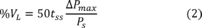 Where: 50
= 100% divided by the leak-check time of 2 minutes.
Where: 50
= 100% divided by the leak-check time of 2 minutes.
8.2.2.5 Leak volumes in excess of 4 percent of the FTIR system volume VSS are unacceptable.
8.3 Detector Linearity. Once an optical configuration is chosen, use one of the procedures of sections 8.3.1 through 8.3.3 to verify that the detector response is linear. If the detector response is not linear, decrease the aperture, or attenuate the infrared beam. After a change in the instrument configuration perform a linearity check until it is demonstrated that the detector response is linear.
8.3.1 Vary the power incident on the detector by modifying the aperture setting. Measure the background and CTS at three instrument aperture settings: (1) at the aperture setting to be used in the testing, (2) at one half this aperture and (3) at twice the proposed testing aperture. Compare the three CTS spectra. CTS band areas shall agree to within the uncertainty of the cylinder standard and the RMSD noise in the system. If test aperture is the maximum aperture, collect CTS spectrum at maximum aperture, then close the aperture to reduce the IR throughput by half. Collect a second background and CTS at the smaller aperture setting and compare the spectra again.
8.3.2 Use neutral density filters to attenuate the infrared beam. Set up the FTIR system as it will be used in the test measurements. Collect a CTS spectrum. Use a neutral density filter to attenuate the infrared beam (either immediately after the source or the interferometer) to approximately 1/2 its original intensity. Collect a second CTS spectrum. Use another filter to attenuate the infrared beam to approximately 1/4 its original intensity. Collect a third background and CTS spectrum. Compare the CTS spectra. CTS band areas shall agree to within the uncertainty of the cylinder standard and the RMSD noise in the system.
8.3.3 Observe the single beam instrument response in a frequency region where the detector response is known to be zero. Verify that the detector response is “flat” and equal to zero in these regions.
8.4 Data Storage Requirements. All field test spectra shall be stored on a computer disk and a second backup copy must stored on a separate disk. The stored information includes sample interferograms, processed absorbance spectra, background interferograms, CTS sample interferograms and CTS absorbance spectra. Additionally, documentation of all sample conditions, instrument settings, and test records must be recorded on hard copy or on computer medium. Table 1 gives a sample presentation of documentation.
8.5 Background Spectrum. Evacuate the gas cell to ≤5 mmHg, and fill with dry nitrogen gas to ambient pressure (or purge the cell with 10 volumes of dry nitrogen). Verify that no significant amounts of absorbing species (for example water vapor and CO2) are present. Collect a background spectrum, using a signal averaging period equal to or greater than the averaging period for the sample spectra. Assign a unique file name to the background spectrum. Store two copies of the background interferogram and processed single-beam spectrum on separate computer disks (one copy is the back-up).
8.5.1 Interference Spectra. If possible, collect spectra of known and suspected major interferences using the same optical system that will be used in the field measurements. This can be done on-site or earlier. A number of gases, e.g. CO2, SO2, CO, NH3, are readily available from cylinder gas suppliers.
8.5.2 Water vapor spectra can be prepared by the following procedure. Fill a sample tube with distilled water. Evacuate above the sample and remove dissolved gasses by alternately freezing and thawing the water while evacuating. Allow water vapor into the FTIR cell, then dilute to atmospheric pressure with nitrogen or dry air. If quantitative water spectra are required, follow the reference spectrum procedure for neat samples (protocol, section 4.6). Often, interference spectra need not be quantitative, but for best results the absorbance must be comparable to the interference absorbance in the sample spectra.
8.6 Pre-Test Calibrations
8.6.1 Calibration Transfer Standard. Evacuate the gas cell to ≤5 mmHg absolute pressure, and fill the FTIR cell to atmospheric pressure with the CTS gas. Alternatively, purge the cell with 10 cell volumes of CTS gas. (If purge is used, verify that the CTS concentration in the cell is stable by collecting two spectra 2 minutes apart as the CTS gas continues to flow. If the absorbance in the second spectrum is no greater than in the first, within the uncertainty of the gas standard, then this can be used as the CTS spectrum.) Record the spectrum.
8.6.2 QA Spike. This procedure assumes that the method has been validated for at least some of the target analytes at the source. For emissions testing perform a QA spike. Use a certified standard, if possible, of an analyte, which has been validated at the source. One analyte standard can serve as a QA surrogate for other analytes which are less reactive or less soluble than the standard. Perform the spike procedure of section 9.2 of this method. Record spectra of at least three independent (section 3.22 of this method) spiked samples. Calculate the spiked component of the analyte concentration. If the average spiked concentration is within 0.7 to 1.3 times the expected concentration, then proceed with the testing. If applicable, apply the correction factor from the Method 301 of this appendix validation test (not the result from the QA spike).
8.7 Sampling. If analyte concentrations vary rapidly with time, continuous sampling is preferable using the smallest cell volume, fastest sampling rate and fastest spectra collection rate possible. Continuous sampling requires the least operator intervention even without an automated sampling system. For continuous monitoring at one location over long periods, Continuous sampling is preferred. Batch sampling and continuous static sampling are used for screening and performing test runs of finite duration. Either technique is preferred for sampling several locations in a matter of days. Batch sampling gives reasonably good time resolution and ensures that each spectrum measures a discreet (and unique) sample volume. Continuous static (and continuous) sampling provide a very stable background over long periods. Like batch sampling, continuous static sampling also ensures that each spectrum measures a unique sample volume. It is essential that the leak check procedure under vacuum (section 8.2 of this method) is passed if the batch sampling procedure is used. It is essential that the leak check procedure under positive pressure is passed if the continuous static or continuous sampling procedures are used. The sampling techniques are described in sections 8.7.1 through 8.7.2 of this method.
8.7.1 Batch Sampling. Evacuate the absorbance cell to ≤5 mmHg absolute pressure. Fill the cell with exhaust gas to ambient pressure, isolate the cell, and record the spectrum. Before taking the next sample, evacuate the cell until no spectral evidence of sample absorption remains. Repeat this procedure to collect eight spectra of separate samples in 1 hour.
8.7.2 Continuous Static Sampling. Purge the FTIR cell with 10 cell volumes of sample gas. Isolate the cell, collect the spectrum of the static sample and record the pressure. Before measuring the next sample, purge the cell with 10 more cell volumes of sample gas.
8.8 Sampling QA and Reporting
8.8.1 Sample integration times shall be sufficient to achieve the required signal-to-noise ratio. Obtain an absorbance spectrum by filling the cell with N2. Measure the RMSD in each analytical region in this absorbance spectrum. Verify that the number of scans used is sufficient to achieve the target MAU.
8.8.2 Assign a unique file name to each spectrum.
8.8.3 Store two copies of sample interferograms and processed spectra on separate computer disks.
8.8.4 For each sample spectrum, document the sampling conditions, the sampling time (while the cell was being filled), the time the spectrum was recorded, the instrumental conditions (path length, temperature, pressure, resolution, signal integration time), and the spectral file name. Keep a hard copy of these data sheets.
8.9 Signal Transmittance. While sampling, monitor the signal transmittance. If signal transmittance (relative to the background) changes by 5 percent or more (absorbance = -.02 to .02) in any analytical spectral region, obtain a new background spectrum.
8.10 Post-test CTS. After the sampling run, record another CTS spectrum.
8.11 Post-test QA
8.11.1 Inspect the sample spectra immediately after the run to verify that the gas matrix composition was close to the expected (assumed) gas matrix.
8.11.2 Verify that the sampling and instrumental parameters were appropriate for the conditions encountered. For example, if the moisture is much greater than anticipated, it may be necessary to use a shorter path length or dilute the sample.
8.11.3 Compare the pre- and post-test CTS spectra. The peak absorbance in pre- and post-test CTS must be ±5 percent of the mean value. See appendix E of the FTIR Protocol.
9.0 Quality ControlUse analyte spiking (sections 8.6.2, 9.2 and 13.0 of this method) to verify that the sampling system can transport the analytes from the probe to the FTIR system.
9.1 Spike Materials. Use a certified standard (accurate to ±2 percent) of the target analyte, if one can be obtained. If a certified standard cannot be obtained, follow the procedures in section 4.6.2.2 of the FTIR Protocol.
9.2 Spiking Procedure. QA spiking (section 8.6.2 of this method) is a calibration procedure used before testing. QA spiking involves following the spike procedure of sections 9.2.1 through 9.2.3 of this method to obtain at least three spiked samples. The analyte concentrations in the spiked samples shall be compared to the expected spike concentration to verify that the sampling/analytical system is working properly. Usually, when QA spiking is used, the method has already been validated at a similar source for the analyte in question. The QA spike demonstrates that the validated sampling/analytical conditions are being duplicated. If the QA spike fails then the sampling/analytical system shall be repaired before testing proceeds. The method validation procedure (section 13.0 of this method) involves a more extensive use of the analyte spike procedure of sections 9.2.1 through 9.2.3 of this method. Spectra of at least 12 independent spiked and 12 independent unspiked samples are recorded. The concentration results are analyzed statistically to determine if there is a systematic bias in the method for measuring a particular analyte. If there is a systematic bias, within the limits allowed by Method 301 of this appendix, then a correction factor shall be applied to the analytical results. If the systematic bias is greater than the allowed limits, this method is not valid and cannot be used.
9.2.1 Introduce the spike/tracer gas at a constant flow rate of ≤10 percent of the total sample flow, when possible.
Note:Use the rotameter at the end of the sampling train to estimate the required spike/tracer gas flow rate.
Use a flow device, e.g., mass flow meter (# 2 percent), to monitor the spike flow rate. Record the spike flow rate every 10 minutes.
9.2.2 Determine the response time (RT) of the system by continuously collecting spectra of the spiked effluent until the spectrum of the spiked component is constant for 5 minutes. The RT is the interval from the first measurement until the spike becomes constant. Wait for twice the duration of the RT, then collect spectra of two independent spiked gas samples. Duplicate analyses of the spiked concentration shall be within 5 percent of the mean of the two measurements.
9.2.3 Calculate the dilution ratio using the tracer gas as follows:

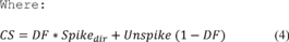 DF = Dilution
factor of the spike gas; this value shall be ≥10. SF6(dir) = SF6
(or tracer gas) concentration measured directly in undiluted spike
gas. SF6(spk) = Diluted SF6 (or tracer gas) concentration measured
in a spiked sample. Spikedir = Concentration of the analyte in the
spike standard measured by filling the FTIR cell directly. CS =
Expected concentration of the spiked samples. Unspike = Native
concentration of analytes in unspiked samples. 10.0 Calibration and
Standardization
DF = Dilution
factor of the spike gas; this value shall be ≥10. SF6(dir) = SF6
(or tracer gas) concentration measured directly in undiluted spike
gas. SF6(spk) = Diluted SF6 (or tracer gas) concentration measured
in a spiked sample. Spikedir = Concentration of the analyte in the
spike standard measured by filling the FTIR cell directly. CS =
Expected concentration of the spiked samples. Unspike = Native
concentration of analytes in unspiked samples. 10.0 Calibration and
Standardization
10.1 Signal-to-Noise Ratio (S/N). The RMSD in the noise must be less than one tenth of the minimum analyte peak absorbance in each analytical region. For example if the minimum peak absorbance is 0.01 at the required DL, then RMSD measured over the entire analytical region must be ≤0.001.
10.2 Absorbance Path length. Verify the absorbance path length by comparing reference CTS spectra to test CTS spectra. See appendix E of the FTIR Protocol.
10.3 Instrument Resolution. Measure the line width of appropriate test CTS band(s) to verify instrument resolution. Alternatively, compare CTS spectra to a reference CTS spectrum, if available, measured at the nominal resolution.
10.4 Apodization Function.In transforming the sample interferograms to absorbance spectra use the same apodization function that was used in transforming the reference spectra.
10.5 FTIR Cell Volume. Evacuate the cell to ≤5 mmHg. Measure the initial absolute temperature (Ti) and absolute pressure (Pi). Connect a wet test meter (or a calibrated dry gas meter), and slowly draw room air into the cell. Measure the meter volume (Vm), meter absolute temperature (Tm), and meter absolute pressure (Pm); and the cell final absolute temperature (Tf) and absolute pressure (Pf). Calculate the FTIR cell volume VSS, including that of the connecting tubing, as follows:
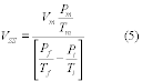 11.0 Data
Analysis and Calculations
11.0 Data
Analysis and Calculations
Analyte concentrations shall be measured using reference spectra from the EPA FTIR spectral library. When EPA library spectra are not available, the procedures in section 4.6 of the Protocol shall be followed to prepare reference spectra of all the target analytes.
11.1 Spectral De-resolution. Reference spectra can be converted to lower resolution standard spectra (section 3.3 of this method) by truncating the original reference sample and background interferograms. Appendix K of the FTIR Protocol gives specific deresolution procedures. Deresolved spectra shall be transformed using the same apodization function and level of zero filling as the sample spectra. Additionally, pre-test FTIR protocol calculations (e.g., FRU, MAU, FCU) shall be performed using the de-resolved standard spectra.
11.2 Data Analysis. Various analytical programs are available for relating sample absorbance to a concentration standard. Calculated concentrations shall be verified by analyzing residual baselines after mathematically subtracting scaled reference spectra from the sample spectra. A full description of the data analysis and calculations is contained in the FTIR Protocol (sections 4.0, 5.0, 6.0 and appendices). Correct the calculated concentrations in the sample spectra for differences in absorption path length and temperature between the reference and sample spectra using equation 6,
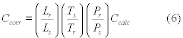 Where:
Ccorr = Concentration, corrected for path length. Ccalc =
Concentration, initial calculation (output of the analytical
program designed for the compound). Lr = Reference spectra path
length. Ls = Sample spectra path length. Ts = Absolute temperature
of the sample gas, K. Tr = Absolute gas temperature of reference
spectra, K. Ps = Sample cell pressure. Pr = Reference spectrum
sample pressure. 12.0 Method Performance
Where:
Ccorr = Concentration, corrected for path length. Ccalc =
Concentration, initial calculation (output of the analytical
program designed for the compound). Lr = Reference spectra path
length. Ls = Sample spectra path length. Ts = Absolute temperature
of the sample gas, K. Tr = Absolute gas temperature of reference
spectra, K. Ps = Sample cell pressure. Pr = Reference spectrum
sample pressure. 12.0 Method Performance
12.1 Spectral Quality. Refer to the FTIR Protocol appendices for analytical requirements, evaluation of data quality, and analysis of uncertainty.
12.2 Sampling QA/QC. The analyte spike procedure of section 9 of this method, the QA spike of section 8.6.2 of this method, and the validation procedure of section 13 of this method are used to evaluate the performance of the sampling system and to quantify sampling system effects, if any, on the measured concentrations. This method is self-validating provided that the results meet the performance requirement of the QA spike in sections 9.0 and 8.6.2 of this method and results from a previous method validation study support the use of this method in the application. Several factors can contribute to uncertainty in the measurement of spiked samples. Factors which can be controlled to provide better accuracy in the spiking procedure are listed in sections 12.2.1 through 12.2.4 of this method.
12.2.1 Flow meter. An accurate mass flow meter is accurate to ±1 percent of its span. If a flow of 1 L/min is monitored with such a MFM, which is calibrated in the range of 0-5 L/min, the flow measurement has an uncertainty of 5 percent. This may be improved by re-calibrating the meter at the specific flow rate to be used.
12.2.2 Calibration gas. Usually the calibration standard is certified to within ±2 percent. With reactive analytes, such as HCl, the certified accuracy in a commercially available standard may be no better than ±5 percent.
12.2.3 Temperature. Temperature measurements of the cell shall be quite accurate. If practical, it is preferable to measure sample temperature directly, by inserting a thermocouple into the cell chamber instead of monitoring the cell outer wall temperature.
12.2.4 Pressure. Accuracy depends on the accuracy of the barometer, but fluctuations in pressure throughout a day may be as much as 2.5 percent due to weather variations.
13.0 Method Validation ProcedureThis validation procedure, which is based on EPA Method 301 (40 CFR part 63, appendix (A), may be used to validate this method for the analytes in a gas matrix. Validation at one source may also apply to another type of source, if it can be shown that the exhaust gas characteristics are similar at both sources.
13.1 Section 6.0 of Method 301 (40 CFR part 63, appendix A), the Analyte Spike procedure, is used with these modifications. The statistical analysis of the results follows section 12.0 of EPA Method 301. Section 3 of this method defines terms that are not defined in Method 301.
13.1.1 The analyte spike is performed dynamically. This means the spike flow is continuous and constant as spiked samples are measured.
13.1.2 The spike gas is introduced at the back of the sample probe.
13.1.3 Spiked effluent is carried through all sampling components downstream of the probe.
13.1.4 A single FTIR system (or more) may be used to collect and analyze spectra (not quadruplicate integrated sampling trains).
13.1.5 All of the validation measurements are performed sequentially in a single “run” (section 3.26 of this method).
13.1.6 The measurements analyzed statistically are each independent (section 3.22 of this method).
13.1.7 A validation data set can consist of more than 12 spiked and 12 unspiked measurements.
13.2 Batch Sampling. The procedure in sections 13.2.1 through 13.2.2 may be used for stable processes. If process emissions are highly variable, the procedure in section 13.2.3 shall be used.
13.2.1 With a single FTIR instrument and sampling system, begin by collecting spectra of two unspiked samples. Introduce the spike flow into the sampling system and allow 10 cell volumes to purge the sampling system and FTIR cell. Collect spectra of two spiked samples. Turn off the spike and allow 10 cell volumes of unspiked sample to purge the FTIR cell. Repeat this procedure until the 24 (or more) samples are collected.
13.2.2 In batch sampling, collect spectra of 24 distinct samples. (Each distinct sample consists of filling the cell to ambient pressure after the cell has been evacuated.)
13.2.3 Alternatively, a separate probe assembly, line, and sample pump can be used for spiked sample. Verify and document that sampling conditions are the same in both the spiked and the unspiked sampling systems. This can be done by wrapping both sample lines in the same heated bundle. Keep the same flow rate in both sample lines. Measure samples in sequence in pairs. After two spiked samples are measured, evacuate the FTIR cell, and turn the manifold valve so that spiked sample flows to the FTIR cell. Allow the connecting line from the manifold to the FTIR cell to purge thoroughly (the time depends on the line length and flow rate). Collect a pair of spiked samples. Repeat the procedure until at least 24 measurements are completed.
13.3 Simultaneous Measurements With Two FTIR Systems. If unspiked effluent concentrations of the target analyte(s) vary significantly with time, it may be desirable to perform synchronized measurements of spiked and unspiked sample. Use two FTIR systems, each with its own cell and sampling system to perform simultaneous spiked and unspiked measurements. The optical configurations shall be similar, if possible. The sampling configurations shall be the same. One sampling system and FTIR analyzer shall be used to measure spiked effluent. The other sampling system and FTIR analyzer shall be used to measure unspiked flue gas. Both systems shall use the same sampling procedure (i.e., batch or continuous).
13.3.1 If batch sampling is used, synchronize the cell evacuation, cell filling, and collection of spectra. Fill both cells at the same rate (in cell volumes per unit time).
13.3.2 If continuous sampling is used, adjust the sample flow through each gas cell so that the same number of cell volumes pass through each cell in a given time (i.e. TC1 = TC2).
13.4 Statistical Treatment. The statistical procedure of EPA Method 301 of this appendix, section 12.0 is used to evaluate the bias and precision. For FTIR testing a validation “run” is defined as spectra of 24 independent samples, 12 of which are spiked with the analyte(s) and 12 of which are not spiked.
13.4.1 Bias. Determine the bias (defined by EPA Method 301 of this appendix, section 12.1.1) using equation 7:
B=Sm − CS Where: B = Bias at spike level. Sm = Mean concentration of the analyte spiked samples. CS = Expected concentration of the spiked samples.13.4.2 Correction Factor. Use section 6.3.2.2 of Method 301 of this appendix to evaluate the statistical significance of the bias. If it is determined that the bias is significant, then use section 6.3.3 of Method 301 to calculate a correction factor (CF). Analytical results of the test method are multiplied by the correction factor, if 0.7 ≤CF ≤1.3. If is determined that the bias is significant and CF >±30 percent, then the test method is considered to “not valid.”
13.4.3 If measurements do not pass validation, evaluate the sampling system, instrument configuration, and analytical system to determine if improper set-up or a malfunction was the cause. If so, repair the system and repeat the validation.
14.0 Pollution PreventionThe extracted sample gas is vented outside the enclosure containing the FTIR system and gas manifold after the analysis. In typical method applications the vented sample volume is a small fraction of the source volumetric flow and its composition is identical to that emitted from the source. When analyte spiking is used, spiked pollutants are vented with the extracted sample gas. Approximately 1.6 × 10⁻⁴ to 3.2 × 10⁻⁴ lbs of a single HAP may be vented to the atmosphere in a typical validation run of 3 hours. (This assumes a molar mass of 50 to 100 g, spike rate of 1.0 L/min, and a standard concentration of 100 ppm). Minimize emissions by keeping the spike flow off when not in use.
15.0 Waste ManagementSmall volumes of laboratory gas standards can be vented through a laboratory hood. Neat samples must be packed and disposed according to applicable regulations. Surplus materials may be returned to supplier for disposal.
16.0 References1. “Field Validation Test Using Fourier Transform Infrared (FTIR) Spectrometry To Measure Formaldehyde, Phenol and Methanol at a Wool Fiberglass Production Facility.” Draft. U.S. Environmental Protection Agency Report, EPA Contract No. 68D20163, Work Assignment I-32, September 1994.
2. “FTIR Method Validation at a Coal-Fired Boiler”. Prepared for U.S. Environmental Protection Agency, Research Triangle Park, NC. Publication No.: EPA-454/R95-004, NTIS No.: PB95-193199. July, 1993.
3. “Method 301 - Field Validation of Pollutant Measurement Methods from Various Waste Media,” 40 CFR part 63, appendix A.
4. “Molecular Vibrations; The Theory of Infrared and Raman Vibrational Spectra,” E. Bright Wilson, J.C. Decius, and P.C. Cross, Dover Publications, Inc., 1980. For a less intensive treatment of molecular rotational-vibrational spectra see, for example, “Physical Chemistry,” G.M. Barrow, chapters 12, 13, and 14, McGraw Hill, Inc., 1979.
5. “Fourier Transform Infrared Spectrometry,” Peter R. Griffiths and James de Haseth, Chemical Analysis, 83, 16-25,(1986), P.J. Elving, J.;D. Winefordner and I.M. Kolthoff (ed.), John Wiley and Sons.
6. “Computer-Assisted Quantitative Infrared Spectroscopy,” Gregory L. McClure (ed.), ASTM Special Publication 934 (ASTM), 1987.
7. “Multivariate Least-Squares Methods Applied to the Quantitative Spectral Analysis of Multicomponent Mixtures,” Applied Spectroscopy, 39(10), 73-84, 1985.
Table 1 - Example Presentation of Sampling Documentation
| Sample time | Spectrum file name | Background file name | Sample conditioning | Process condition |
|---|---|---|---|---|
| Sample time | Spectrum file | Interferogram | Resolution | Scans | Apodization | Gain | CTS Spectrum |
|---|---|---|---|---|---|---|---|
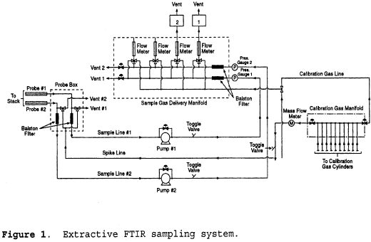
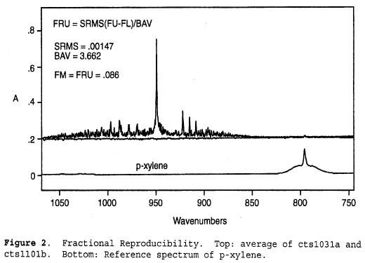 Addendum to Test
Method 320 - Protocol for the Use of Extractive Fourier Transform
Infrared (FTIR) Spectrometry for the Analyses of Gaseous Emissions
from Stationary Sources 1.0 Introduction
Addendum to Test
Method 320 - Protocol for the Use of Extractive Fourier Transform
Infrared (FTIR) Spectrometry for the Analyses of Gaseous Emissions
from Stationary Sources 1.0 Introduction
The purpose of this addendum is to set general guidelines for the use of modern FTIR spectroscopic methods for the analysis of gas samples extracted from the effluent of stationary emission sources. This addendum outlines techniques for developing and evaluating such methods and sets basic requirements for reporting and quality assurance procedures.
1.1 Nomenclature
1.1.1 Appendix A to this addendum lists definitions of the symbols and terms used in this Protocol, many of which have been taken directly from American Society for Testing and Materials (ASTM) publication E 131-90a, entitled “Terminology Relating to Molecular Spectroscopy.”
1.1.2 Except in the case of background spectra or where otherwise noted, the term “spectrum” refers to a double-beam spectrum in units of absorbance vs. wavenumber (cm−1).
1.1.3 The term “Study” in this addendum refers to a publication that has been subjected to EPA- or peer-review.
2.0 Applicability and Analytical Principle2.1 Applicability. This Protocol applies to the determination of compound-specific concentrations in single- and multiple-component gas phase samples using double-beam absorption spectroscopy in the mid-infrared band. It does not specifically address other FTIR applications, such as single-beam spectroscopy, analysis of open-path (non-enclosed) samples, and continuous measurement techniques. If multiple spectrometers, absorption cells, or instrumental linewidths are used in such analyses, each distinct operational configuration of the system must be evaluated separately according to this Protocol.
2.2 Analytical Principle
2.2.1 In the mid-infrared band, most molecules exhibit characteristic gas phase absorption spectra that may be recorded by FTIR systems. Such systems consist of a source of mid-infrared radiation, an interferometer, an enclosed sample cell of known absorption pathlength, an infrared detector, optical elements for the transfer of infrared radiation between components, and gas flow control and measurement components. Adjunct and integral computer systems are used for controlling the instrument, processing the signal, and for performing both Fourier transforms and quantitative analyses of spectral data.
2.2.2 The absorption spectra of pure gases and of mixtures of gases are described by a linear absorbance theory referred to as Beer's Law. Using this law, modern FTIR systems use computerized analytical programs to quantify compounds by comparing the absorption spectra of known (reference) gas samples to the absorption spectrum of the sample gas. Some standard mathematical techniques used for comparisons are classical least squares, inverse least squares, cross-correlation, factor analysis, and partial least squares. Reference A describes several of these techniques, as well as additional techniques, such as differentiation methods, linear baseline corrections, and non-linear absorbance corrections.
3.0 General Principles of Protocol RequirementsThe characteristics that distinguish FTIR systems from gas analyzers used in instrumental gas analysis methods (e.g., Methods 6C and 7E of appendix A to part 60 of this chapter) are: (1) Computers are necessary to obtain and analyze data; (2) chemical concentrations can be quantified using previously recorded infrared reference spectra; and (3) analytical assumptions and results, including possible effects of interfering compounds, can be evaluated after the quantitative analysis. The following general principles and requirements of this Protocol are based on these characteristics.
3.1 Verifiability and Reproducibility of Results. Store all data and document data analysis techniques sufficient to allow an independent agent to reproduce the analytical results from the raw interferometric data.
3.2 Transfer of Reference Spectra. To determine whether reference spectra recorded under one set of conditions (e.g., optical bench, instrumental linewidth, absorption pathlength, detector performance, pressure, and temperature) can be used to analyze sample spectra taken under a different set of conditions, quantitatively compare “calibration transfer standards” (CTS) and reference spectra as described in this Protocol.
Note:The CTS may, but need not, include analytes of interest). To effect this, record the absorption spectra of the CTS (a) immediately before and immediately after recording reference spectra and (b) immediately after recording sample spectra.
3.3 Evaluation of FTIR Analyses. The applicability, accuracy, and precision of FTIR measurements are influenced by a number of interrelated factors, which may be divided into two classes:
3.3.1 Sample-Independent Factors. Examples are system configuration and performance (e.g., detector sensitivity and infrared source output), quality and applicability of reference absorption spectra, and type of mathematical analyses of the spectra. These factors define the fundamental limitations of FTIR measurements for a given system configuration. These limitations may be estimated from evaluations of the system before samples are available. For example, the detection limit for the absorbing compound under a given set of conditions may be estimated from the system noise level and the strength of a particular absorption band. Similarly, the accuracy of measurements may be estimated from the analysis of the reference spectra.
3.3.2 Sample-Dependent Factors. Examples are spectral interferants (e.g., water vapor and CO2) or the overlap of spectral features of different compounds and contamination deposits on reflective surfaces or transmitting windows. To maximize the effectiveness of the mathematical techniques used in spectral analysis, identification of interferants (a standard initial step) and analysis of samples (includes effect of other analytical errors) are necessary. Thus, the Protocol requires post-analysis calculation of measurement concentration uncertainties for the detection of these potential sources of measurement error.
4.0 Pre-Test Preparations and EvaluationsBefore testing, demonstrate the suitability of FTIR spectrometry for the desired application according to the procedures of this section.
4.1 Identify Test Requirements. Identify and record the test requirements described in sections 4.1.1 through 4.1.4 of this addendum. These values set the desired or required goals of the proposed analysis; the description of methods for determining whether these goals are actually met during the analysis comprises the majority of this Protocol.
4.1.1 Analytes (specific chemical species) of interest. Label the analytes from i = 1 to I.
4.1.2 Analytical uncertainty limit (AUi). The AUi is the maximum permissible fractional uncertainty of analysis for the i th analyte concentration, expressed as a fraction of the analyte concentration in the sample.
4.1.3 Required detection limit for each analyte (DLi, ppm). The detection limit is the lowest concentration of an analyte for which its overall fractional uncertainty (OFUi) is required to be less than its analytical uncertainty limit (AUi).
4.1.4 Maximum expected concentration of each analyte (CMAXi, ppm).
4.2 Identify Potential Interferants. Considering the chemistry of the process or results of previous studies, identify potential interferants, i.e., the major effluent constituents and any relatively minor effluent constituents that possess either strong absorption characteristics or strong structural similarities to any analyte of interest. Label them 1 through Nj, where the subscript “j” pertains to potential interferants. Estimate the concentrations of these compounds in the effluent (CPOTj, ppm).
4.3 Select and Evaluate the Sampling System. Considering the source, e.g., temperature and pressure profiles, moisture content, analyte characteristics, and particulate concentration), select the equipment for extracting gas samples. Recommended are a particulate filter, heating system to maintain sample temperature above the dew point for all sample constituents at all points within the sampling system (including the filter), and sample conditioning system (e.g., coolers, water-permeable membranes that remove water or other compounds from the sample, and dilution devices) to remove spectral interferants or to protect the sampling and analytical components. Determine the minimum absolute sample system pressure (Pmin, mmHg) and the infrared absorption cell volume (VSS, liter). Select the techniques and/or equipment for the measurement of sample pressures and temperatures.
4.4 Select Spectroscopic System. Select a spectroscopic configuration for the application. Approximate the absorption pathlength (LS′, meter), sample pressure (PS′, kPa), absolute sample temperature TS′, and signal integration period (tSS, seconds) for the analysis. Specify the nominal minimum instrumental linewidth (MIL) of the system. Verify that the fractional error at the approximate values PS′ and TS′ is less than one half the smallest value AUi (see section 4.1.2 of this addendum).
4.5 Select Calibration Transfer Standards (CTS's). Select CTS's that meet the criteria listed in sections 4.5.1, 4.5.2, and 4.5.3 of this addendum.
Note:It may be necessary to choose preliminary analytical regions (see section 4.7 of this addendum), identify the minimum analyte linewidths, or estimate the system noise level (see section 4.12 of this addendum) before selecting the CTS. More than one compound may be needed to meet the criteria; if so, obtain separate cylinders for each compound.
4.5.1 The central wavenumber position of each analytical region shall lie within 25 percent of the wavenumber position of at least one CTS absorption band.
4.5.2 The absorption bands in section 4.5.1 of this addendum shall exhibit peak absorbances greater than ten times the value RMSEST (see section 4.12 of this addendum) but less than 1.5 absorbance units.
4.5.3 At least one absorption CTS band within the operating range of the FTIR instrument shall have an instrument-independent linewidth no greater than the narrowest analyte absorption band. Perform and document measurements or cite Studies to determine analyte and CTS compound linewidths.
4.5.4 For each analytical region, specify the upper and lower wavenumber positions (FFUm and FFLm, respectively) that bracket the CTS absorption band or bands for the associated analytical region. Specify the wavenumber range, FNU to FNL, containing the absorption band that meets the criterion of section 4.5.3 of this addendum.
4.5.5 Associate, whenever possible, a single set of CTS gas cylinders with a set of reference spectra. Replacement CTS gas cylinders shall contain the same compounds at concentrations within 5 percent of that of the original CTS cylinders; the entire absorption spectra (not individual spectral segments) of the replacement gas shall be scaled by a factor between 0.95 and 1.05 to match the original CTS spectra.
4.6 Prepare Reference Spectra
Note:Reference spectra are available in a permanent soft copy from the EPA spectral library on the EMTIC (Emission Measurement Technical Information Center) computer bulletin board; they may be used if applicable.
4.6.1 Select the reference absorption pathlength (LR) of the cell.
4.6.2 Obtain or prepare a set of chemical standards for each analyte, potential and known spectral interferants, and CTS. Select the concentrations of the chemical standards to correspond to the top of the desired range.
4.6.2.1 Commercially-Prepared Chemical Standards. Chemical standards for many compounds may be obtained from independent sources, such as a specialty gas manufacturer, chemical company, or commercial laboratory. These standards (accurate to within ±2 percent) shall be prepared according to EPA Traceability Protocol (see Reference D) or shall be traceable to NIST standards. Obtain from the supplier an estimate of the stability of the analyte concentration. Obtain and follow all of the supplier's recommendations for recertifying the analyte concentration.
4.6.2.2 Self-Prepared Chemical Standards. Chemical standards may be prepared by diluting certified commercially prepared chemical gases or pure analytes with ultra-pure carrier (UPC) grade nitrogen according to the barometric and volumetric techniques generally described in Reference A, section A4.6.
4.6.3 Record a set of the absorption spectra of the CTS {R1}, then a set of the reference spectra at two or more concentrations in duplicate over the desired range (the top of the range must be less than 10 times that of the bottom), followed by a second set of CTS spectra {R2}. (If self-prepared standards are used, see section 4.6.5 of this addendum before disposing of any of the standards.) The maximum accepted standard concentration-pathlength product (ASCPP) for each compound shall be higher than the maximum estimated concentration-pathlength products for both analytes and known interferants in the effluent gas. For each analyte, the minimum ASCPP shall be no greater than ten times the concentration-pathlength product of that analyte at its required detection limit.
4.6.4 Permanently store the background and interferograms in digitized form. Document details of the mathematical process for generating the spectra from these interferograms. Record the sample pressure (PR), sample temperature (TR), reference absorption pathlength (LR), and interferogram signal integration period (tSR). Signal integration periods for the background interferograms shall be ≥tSR. Values of PR, LR, and tSR shall not deviate by more than ±1 percent from the time of recording [R1] to that of recording [R2].
4.6.5 If self-prepared chemical standards are employed and spectra of only two concentrations are recorded for one or more compounds, verify the accuracy of the dilution technique by analyzing the prepared standards for those compounds with a secondary (non-FTIR) technique in accordance with sections 4.6.5.1 through 4.6.5.4 of this addendum.
4.6.5.1 Record the response of the secondary technique to each of the four standards prepared.
4.6.5.2 Perform a linear regression of the response values (dependant variable) versus the accepted standard concentration (ASC) values (independent variable), with the regression constrained to pass through the zero-response, zero ASC point.
4.6.5.3 Calculate the average fractional difference between the actual response values and the regression-predicted values (those calculated from the regression line using the four ASC values as the independent variable).
4.6.5.4 If the average fractional difference value calculated in section 4.6.5.3 of this addendum is larger for any compound than the corresponding AUi, the dilution technique is not sufficiently accurate and the reference spectra prepared are not valid for the analysis.
4.7 Select Analytical Regions. Using the general considerations in section 7 of Reference A and the spectral characteristics of the analytes and interferants, select the analytical regions for the application. Label them m = 1 to M. Specify the lower, center and upper wavenumber positions of each analytical region (FLm, FCm, and FUm, respectively). Specify the analytes and interferants which exhibit absorption in each region.
4.8 Determine Fractional Reproducibility Uncertainties. Using appendix E of this addendum, calculate the fractional reproducibility uncertainty for each analyte (FRUi) from a comparison of [R1] and [R2]. If FRUi >AUi for any analyte, the reference spectra generated in accordance with section 4.6 of this addendum are not valid for the application.
4.9 Identify Known Interferants. Using appendix B of this addendum, determine which potential interferants affect the analyte concentration determinations. Relabel these potential interferant as “known” interferants, and designate these compounds from k = 1 to K. Appendix B to this addendum also provides criteria for determining whether the selected analytical regions are suitable.
4.10 Prepare Computerized Analytical Programs
4.10.1 Choose or devise mathematical techniques (e.g, classical least squares, inverse least squares, cross-correlation, and factor analysis) based on equation 4 of Reference A that are appropriate for analyzing spectral data by comparison with reference spectra.
4.10.2 Following the general recommendations of Reference A, prepare a computer program or set of programs that analyzes all of the analytes and known interferants, based on the selected analytical regions (section 4.7 of this addendum) and the prepared reference spectra (section 4.6 of this addendum). Specify the baseline correction technique (e.g., determining the slope and intercept of a linear baseline contribution in each analytical region) for each analytical region, including all relevant wavenumber positions.
4.10.3 Use programs that provide as output [at the reference absorption pathlength (LR), reference gas temperature (TR), and reference gas pressure (PR)] the analyte concentrations, the known interferant concentrations, and the baseline slope and intercept values. If the sample absorption pathlength (LS), sample gas temperature (TS), or sample gas pressure (PS) during the actual sample analyses differ from LR, TR, and PR, use a program or set of programs that applies multiplicative corrections to the derived concentrations to account for these variations, and that provides as output both the corrected and uncorrected values. Include in the report of the analysis (see section 7.0 of this addendum) the details of any transformations applied to the original reference spectra (e.g., differentiation), in such a fashion that all analytical results may be verified by an independent agent from the reference spectra and data spectra alone.
4.11 Determine the Fractional Calibration Uncertainty. Calculate the fractional calibration uncertainty for each analyte (FCUi) according to appendix F of this addendum, and compare these values to the fractional uncertainty limits (AUi; see section 4.1.2 of this addendum). If FCUi >AUi, either the reference spectra or analytical programs for that analyte are unsuitable.
4.12 Verify System Configuration Suitability. Using appendix C of this addendum, measure or obtain estimates of the noise level (RMSEST, absorbance) of the FTIR system. Alternatively, construct the complete spectrometer system and determine the values RMSSm using appendix G of this addendum. Estimate the minimum measurement uncertainty for each analyte (MAUi, ppm) and known interferant (MIUk, ppm) using appendix D of this addendum. Verify that (a) MAUi <(AUi)(DLi), FRUi <AUi, and FCUi <AUi for each analyte and that (b) the CTS chosen meets the requirements listed in sections 4.5.1 through 4.5.5 of this addendum.
5.0 Sampling and Analysis Procedure5.1 Analysis System Assembly and Leak-Test. Assemble the analysis system. Allow sufficient time for all system components to reach the desired temperature. Then, determine the leak-rate (LR) and leak volume (VL), where VL = LR tSS. Leak volumes shall be ≤4 percent of VSS.
5.2 Verify Instrumental Performance. Measure the noise level of the system in each analytical region using the procedure of appendix G of this addendum. If any noise level is higher than that estimated for the system in section 4.12 of this addendum, repeat the calculations of appendix D of this addendum and verify that the requirements of section 4.12 of this addendum are met; if they are not, adjust or repair the instrument and repeat this section.
5.3 Determine the Sample Absorption Pathlength
Record a background spectrum. Then, fill the absorption cell with CTS at the pressure PR and record a set of CTS spectra [R3]. Store the background and unscaled CTS single beam interferograms and spectra. Using appendix H of this addendum, calculate the sample absorption pathlength (LS) for each analytical region. The values LS shall not differ from the approximated sample pathlength LS′ (see section 4.4 of this addendum) by more than 5 percent.
5.4 Record Sample Spectrum. Connect the sample line to the source. Either evacuate the absorption cell to an absolute pressure below 5 mmHg before extracting a sample from the effluent stream into the absorption cell, or pump at least ten cell volumes of sample through the cell before obtaining a sample. Record the sample pressure PS. Generate the absorbance spectrum of the sample. Store the background and sample single beam interferograms, and document the process by which the absorbance spectra are generated from these data. (If necessary, apply the spectral transformations developed in section 5.6.2 of this addendum). The resulting sample spectrum is referred to below as SS.
Note:Multiple sample spectra may be recorded according to the procedures of section 5.4 of this addendum before performing sections 5.5 and 5.6 of this addendum.
5.5 Quantify Analyte Concentrations. Calculate the unscaled analyte concentrations RUAi and unscaled interferant concentrations RUIK using the programs developed in section 4 of this addendum. To correct for pathlength and pressure variations between the reference and sample spectra, calculate the scaling factor, RLPS using equation A.1,
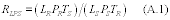 Calculate
the final analyte and interferant concentrations RSAi and RSIk
using equations A.2 and A.3,
Calculate
the final analyte and interferant concentrations RSAi and RSIk
using equations A.2 and A.3, 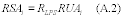
5.6 Determine Fractional Analysis Uncertainty. Fill the absorption cell with CTS at the pressure PS. Record a set of CTS spectra [R4]. Store the background and CTS single beam interferograms. Using appendix H of this addendum, calculate the fractional analysis uncertainty (FAU) for each analytical region. If the FAU indicated for any analytical region is greater than the required accuracy requirements determined in sections 4.1.1 through 4.1.4 of this addendum, then comparisons to previously recorded reference spectra are invalid in that analytical region, and the analyst shall perform one or both of the procedures of sections 5.6.1 through 5.6.2 of this addendum.
5.6.1 Perform instrumental checks and adjust the instrument to restore its performance to acceptable levels. If adjustments are made, repeat sections 5.3, 5.4 (except for the recording of a sample spectrum), and 5.5 of this addendum to demonstrate that acceptable uncertainties are obtained in all analytical regions.
5.6.2 Apply appropriate mathematical transformations (e.g., frequency shifting, zero-filling, apodization, smoothing) to the spectra (or to the interferograms upon which the spectra are based) generated during the performance of the procedures of section 5.3 of this addendum. Document these transformations and their reproducibility. Do not apply multiplicative scaling of the spectra, or any set of transformations that is mathematically equivalent to multiplicative scaling. Different transformations may be applied to different analytical regions. Frequency shifts shall be less than one-half the minimum instrumental linewidth, and must be applied to all spectral data points in an analytical region. The mathematical transformations may be retained for the analysis if they are also applied to the appropriate analytical regions of all sample spectra recorded, and if all original sample spectra are digitally stored. Repeat sections 5.3, 5.4 (except the recording of a sample spectrum), and 5.5 of this addendum to demonstrate that these transformations lead to acceptable calculated concentration uncertainties in all analytical regions.
6.0 Post-Analysis EvaluationsEstimate the overall accuracy of the analyses performed in accordance with sections 5.1 through 5.6 of this addendum using the procedures of sections 6.1 through 6.3 of this addendum.
6.1 Qualitatively Confirm the Assumed Matrix. Examine each analytical region of the sample spectrum for spectral evidence of unexpected or unidentified interferants. If found, identify the interfering compounds (see Reference C for guidance) and add them to the list of known interferants. Repeat the procedures of section 4 of this addendum to include the interferants in the uncertainty calculations and analysis procedures. Verify that the MAU and FCU values do not increase beyond acceptable levels for the application requirements. Re-calculate the analyte concentrations (section 5.5 of this addendum) in the affected analytical regions.
6.2 Quantitatively Evaluate Fractional Model Uncertainty (FMU). Perform the procedures of either section 6.2.1 or 6.2.2 of this addendum:
6.2.1 Using appendix I of this addendum, determine the fractional model error (FMU) for each analyte.
6.2.2 Provide statistically determined uncertainties FMU for each analyte which are equivalent to two standard deviations at the 95 percent confidence level. Such determinations, if employed, must be based on mathematical examinations of the pertinent sample spectra (not the reference spectra alone). Include in the report of the analysis (see section 7.0 of this addendum) a complete description of the determination of the concentration uncertainties.
6.3 Estimate Overall Concentration Uncertainty (OCU). Using appendix J of this addendum, determine the overall concentration uncertainty (OCU) for each analyte. If the OCU is larger than the required accuracy for any analyte, repeat sections 4 and 6 of this addendum.
7.0 Reporting Requirements [Documentation pertaining to virtually all the procedures of sections 4, 5, and 6 will be required. Software copies of reference spectra and sample spectra will be retained for some minimum time following the actual testing.] 8.0 References(A) Standard Practices for General Techniques of Infrared Quantitative Analysis (American Society for Testing and Materials, Designation E 168-88).
(B) The Coblentz Society Specifications for Evaluation of Research Quality Analytical Infrared Reference Spectra (Class II); Anal. Chemistry 47, 945A (1975); Appl. Spectroscopy 444, pp. 211-215, 1990.
(C) Standard Practices for General Techniques for Qualitative Infrared Analysis, American Society for Testing and Materials, Designation E 1252-88.
(D) “EPA Traceability Protocol for Assay and Certification of Gaseous Calibration Standards,” U.S. Environmental Protection Agency Publication No. EPA/600/R-93/224, December 1993.
Appendix A to Addendum to Method 320 - Definitions of Terms and SymbolsA.1 Definitions of Terms. All terms used in this method that are not defined below have the meaning given to them in the CAA and in subpart A of this part.
Absorption band means a contiguous wavenumber region of a spectrum (equivalently, a contiguous set of absorbance spectrum data points) in which the absorbance passes through a maximum or a series of maxima.
Absorption pathlength means the distance in a spectrophotometer, measured in the direction of propagation of the beam of radiant energy, between the surface of the specimen on which the radiant energy is incident and the surface of the specimen from which it is emergent.
Analytical region means a contiguous wavenumber region (equivalently, a contiguous set of absorbance spectrum data points) used in the quantitative analysis for one or more analytes.
Note:The quantitative result for a single analyte may be based on data from more than one analytical region.
Apodization means modification of the ILS function by multiplying the interferogram by a weighing function whose magnitude varies with retardation.
Background spectrum means the single beam spectrum obtained with all system components without sample present.
Baseline means any line drawn on an absorption spectrum to establish a reference point that represents a function of the radiant power incident on a sample at a given wavelength.
Beers's law means the direct proportionality of the absorbance of a compound in a homogeneous sample to its concentration.
Calibration transfer standard (CTS) gas means a gas standard of a compound used to achieve and/or demonstrate suitable quantitative agreement between sample spectra and the reference spectra; see section 4.5.1 of this addendum.
Compound means a substance possessing a distinct, unique molecular structure.
Concentration (c) means the quantity of a compound contained in a unit quantity of sample. The unit “ppm” (number, or mole, basis) is recommended.
Concentration-pathlength product means the mathematical product of concentration of the species and absorption pathlength. For reference spectra, this is a known quantity; for sample spectra, it is the quantity directly determined from Beer's law. The units “centimeters-ppm” or “meters-ppm” are recommended.
Derivative absorption spectrum means a plot of rate of change of absorbance or of any function of absorbance with respect to wavelength or any function of wavelength.
Double beam spectrum means a transmission or absorbance spectrum derived by dividing the sample single beam spectrum by the background spectrum.
Note:The term “double-beam” is used elsewhere to denote a spectrum in which the sample and background interferograms are collected simultaneously along physically distinct absorption paths. Here, the term denotes a spectrum in which the sample and background interferograms are collected at different times along the same absorption path.
Fast Fourier transform (FFT) means a method of speeding up the computation of a discrete FT by factoring the data into sparse matrices containing mostly zeros.
Flyback means interferometer motion during which no data are recorded.
Fourier transform (FT) means the mathematical process for converting an amplitude-time spectrum to an amplitude-frequency spectrum, or vice versa.
Fourier transform infrared (FTIR) spectrometer means an analytical system that employs a source of mid-infrared radiation, an interferometer, an enclosed sample cell of known absorption pathlength, an infrared detector, optical elements that transfer infrared radiation between components, and a computer system. The time-domain detector response (interferogram) is processed by a Fourier transform to yield a representation of the detector response vs. infrared frequency.
Note:When FTIR spectrometers are interfaced with other instruments, a slash should be used to denote the interface; e.g., GC/FTIR; HPCL/FTIR, and the use of FTIR should be explicit; i.e., FTIR not IR.
Frequency, v means the number of cycles per unit time.
Infrared means the portion of the electromagnetic spectrum containing wavelengths from approximately 0.78 to 800 microns.
Interferogram, I(σ) means record of the modulated component of the interference signal measured as a function of retardation by the detector.
Interferometer means device that divides a beam of radiant energy into two or more paths, generates an optical path difference between the beams, and recombines them in order to produce repetitive interference maxima and minima as the optical retardation is varied.
Linewidth means the full width at half maximum of an absorption band in units of wavenumbers (cm−1).
Mid-infrared means the region of the electromagnetic spectrum from approximately 400 to 5000 cm−1.
Reference spectra means absorption spectra of gases with known chemical compositions, recorded at a known absorption pathlength, which are used in the quantitative analysis of gas samples.
Retardation, σ means optical path difference between two beams in an interferometer; also known as “optical path difference” or “optical retardation.”
Scan means digital representation of the detector output obtained during one complete motion of the interferometer's moving assembly or assemblies.
Scaling means application of a multiplicative factor to the absorbance values in a spectrum.
Single beam spectrum means Fourier-transformed interferogram, representing the detector response vs. wavenumber.
Note:The term “single-beam” is used elsewhere to denote any spectrum in which the sample and background interferograms are recorded on the same physical absorption path; such usage differentiates such spectra from those generated using interferograms recorded along two physically distinct absorption paths (see “double-beam spectrum” above). Here, the term applies (for example) to the two spectra used directly in the calculation of transmission and absorbance spectra of a sample.
Standard reference material means a reference material, the composition or properties of which are certified by a recognized standardizing agency or group.
Note:The equivalent ISO term is “certified reference material.”
Transmittance, T means the ratio of radiant power transmitted by the sample to the radiant power incident on the sample. Estimated in FTIR spectroscopy by forming the ratio of the single-beam sample and background spectra.
Wavenumber, v means the number of waves per unit length.
Note:The usual unit of wavenumber is the reciprocal centimeter, cm−1. The wavenumber is the reciprocal of the wavelength, λ, when λ is expressed in centimeters.
Zero-filling means the addition of zero-valued points to the end of a measured interferogram.
Note:Performing the FT of a zero-filled interferogram results in correctly interpolated points in the computed spectrum.
A.2 Definitions of Mathematical Symbols. The symbols used in equations in this protocol are defined as follows:
(1) A, absorbance = the logarithm to the base 10 of the reciprocal of the transmittance (T).
(2) AAIim = band area of the i th analyte in the m th analytical region, at the concentration (CLi) corresponding to the product of its required detection limit (DLi) and analytical uncertainty limit (AUi) .
(3) AAVim = average absorbance of the i th analyte in the m th analytical region, at the concentration (CLi) corresponding to the product of its required detection limit (DLi) and analytical uncertainty limit (AUi).
(4) ASC, accepted standard concentration = the concentration value assigned to a chemical standard.
(5) ASCPP, accepted standard concentration-pathlength product = for a chemical standard, the product of the ASC and the sample absorption pathlength. The units “centimeters-ppm” or “meters-ppm” are recommended.
(6) AUi, analytical uncertainty limit = the maximum permissible fractional uncertainty of analysis for the i th analyte concentration, expressed as a fraction of the analyte concentration determined in the analysis.
(7) AVTm = average estimated total absorbance in the m th analytical region.
(8) CKWNk = estimated concentration of the k th known interferant.
(9) CMAXi = estimated maximum concentration of the i th analyte.
(10) CPOTj = estimated concentration of the j th potential interferant.
(11) DLi, required detection limit = for the i th analyte, the lowest concentration of the analyte for which its overall fractional uncertainty (OFUi) is required to be less than the analytical uncertainty limit (AUi).
(12) FCm = center wavenumber position of the m th analytical region.
(13) FAUi, fractional analytical uncertainty = calculated uncertainty in the measured concentration of the i th analyte because of errors in the mathematical comparison of reference and sample spectra.
(14) FCUi, fractional calibration uncertainty = calculated uncertainty in the measured concentration of the i th analyte because of errors in Beer's law modeling of the reference spectra concentrations.
(15) FFLm = lower wavenumber position of the CTS absorption band associated with the m th analytical region.
(16) FFUm = upper wavenumber position of the CTS absorption band associated with the m th analytical region.
(17) FLm = lower wavenumber position of the m th analytical region.
(18) FMUi, fractional model uncertainty = calculated uncertainty in the measured concentration of the i th analyte because of errors in the absorption model employed.
(19) FNL = lower wavenumber position of the CTS spectrum containing an absorption band at least as narrow as the analyte absorption bands.
(20) FNU = upper wavenumber position of the CTS spectrum containing an absorption band at least as narrow as the analyte absorption bands.
(21) FRUi, fractional reproducibility uncertainty = calculated uncertainty in the measured concentration of the i th analyte because of errors in the reproducibility of spectra from the FTIR system.
(22) FUm = upper wavenumber position of the m th analytical region.
(23) IAIjm = band area of the j th potential interferant in the m th analytical region, at its expected concentration (CPOTj).
(24) IAVim = average absorbance of the i th analyte in the m th analytical region, at its expected concentration (CPOTj).
(25) ISCi or k, indicated standard concentration = the concentration from the computerized analytical program for a single-compound reference spectrum for the i th analyte or k th known interferant.
(26) kPa = kilo-Pascal (see Pascal).
(27) LS′ = estimated sample absorption pathlength.
(28) LR = reference absorption pathlength.
(29) LS = actual sample absorption pathlength.
(30) MAUi = mean of the MAUim over the appropriate analytical regions.
(31) MAUim, minimum analyte uncertainty = the calculated minimum concentration for which the analytical uncertainty limit (AUi) in the measurement of the i th analyte, based on spectral data in the m th analytical region, can be maintained.
(32) MIUj = mean of the MIUjm over the appropriate analytical regions.
(33) MIUjm, minimum interferant uncertainty = the calculated minimum concentration for which the analytical uncertainty limit CPOTj/20 in the measurement of the j th interferant, based on spectral data in the m th analytical region, can be maintained.
(34) MIL, minimum instrumental linewidth = the minimum linewidth from the FTIR system, in wavenumbers.
Note:The MIL of a system may be determined by observing an absorption band known (through higher resolution examinations) to be narrower than indicated by the system. The MIL is fundamentally limited by the retardation of the interferometer, but is also affected by other operational parameters (e.g., the choice of apodization).
(35) Ni = number of analytes.
(36) Nj = number of potential interferants.
(37) Nk = number of known interferants.
(38) Nscan = the number of scans averaged to obtain an interferogram.
(39) OFUi = the overall fractional uncertainty in an analyte concentration determined in the analysis (OFUi = MAX[FRUi, FCUi, FAUi, FMUi]).
(40) Pascal (Pa) = metric unit of static pressure, equal to one Newton per square meter; one atmosphere is equal to 101,325 Pa; 1/760 atmosphere (one Torr, or one millimeter Hg) is equal to 133.322 Pa.
(41) Pmin = minimum pressure of the sampling system during the sampling procedure.
(42) PS′ = estimated sample pressure.
(43) PR = reference pressure.
(44) PS = actual sample pressure.
(45) RMSSm = measured noise level of the FTIR system in the m th analytical region.
(46) RMSD, root mean square difference = a measure of accuracy determined by the following equation:
 Where: n
= the number of observations for which the accuracy is determined.
ei = the difference between a measured value of a property and its
mean value over the n observations. Note:
Where: n
= the number of observations for which the accuracy is determined.
ei = the difference between a measured value of a property and its
mean value over the n observations. Note:
The RMSD value “between a set of n contiguous absorbance values (Ai) and the mean of the values” (AM) is defined as
(47) RSAi = the (calculated) final concentration of the i th analyte.
(48) RSIk = the (calculated) final concentration of the k th known interferant.
(49) tscan, scan time = time used to acquire a single scan, not including flyback.
(50) tS, signal integration period = the period of time over which an interferogram is averaged by addition and scaling of individual scans. In terms of the number of scans Nscan and scan time tscan, tS = Nscantscan.
(51) tSR = signal integration period used in recording reference spectra.
(52) tSS = signal integration period used in recording sample spectra.
(53) TR = absolute temperature of gases used in recording reference spectra.
(54) TS = absolute temperature of sample gas as sample spectra are recorded.
(55) TP, Throughput = manufacturer's estimate of the fraction of the total infrared power transmitted by the absorption cell and transfer optics from the interferometer to the detector.
(56) VSS = volume of the infrared absorption cell, including parts of attached tubing.
(57) Wik = weight used to average over analytical regions k for quantities related to the analyte i; see appendix D of this addendum.
Appendix B to Addendum to Method 320 - Identifying Spectral Interferants B.1 GeneralB.1.1 Assume a fixed absorption pathlength equal to the value LS′.
B.1.2 Use band area calculations to compare the relative absorption strengths of the analytes and potential interferants. In the m th analytical region (FLm to FUm), use either rectangular or trapezoidal approximations to determine the band areas described below (see Reference A, sections A.3.1 through A.3.3). Document any baseline corrections applied to the spectra.
B.1.3 Use the average total absorbance of the analytes and potential interferants in each analytical region to determine whether the analytical region is suitable for analyte concentration determinations.
Note:The average absorbance in an analytical region is the band area divided by the width of the analytical region in wavenumbers. The average total absorbance in an analytical region is the sum of the average absorbances of all analytes and potential interferants.
B.2 CalculationsB.2.1 Prepare spectral representations of each analyte at the concentration CLi = (DLi)(AUi), where DLi is the required detection limit and AUi is the maximum permissible analytical uncertainty. For the m th analytical region, calculate the band area (AAIim) and average absorbance (AAVim) from these scaled analyte spectra.
B.2.2 Prepare spectral representations of each potential interferant at its expected concentration (CPOTj). For the m th analytical region, calculate the band area (IAIjm) and average absorbance (IAVjm) from these scaled potential interferant spectra.
B.2.3 Repeat the calculation for each analytical region, and record the band area results in matrix form as indicated in Figure B.1.
B.2.4 If the band area of any potential interferant in an analytical region is greater than the one-half the band area of any analyte (i.e., IAIjm >0.5 AAIim for any pair ij and any m), classify the potential interferant as a known interferant. Label the known interferants k = 1 to K. Record the results in matrix form as indicated in Figure B.2.
B.2.5 Calculate the average total absorbance (AVTm) for each analytical region and record the values in the last row of the matrix described in Figure B.2. Any analytical region where AVTm >2.0 is unsuitable.
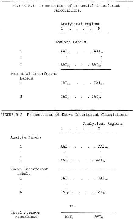 Appendix
C to Addendum to Method 320 - Estimating Noise Levels C.1 General
Appendix
C to Addendum to Method 320 - Estimating Noise Levels C.1 General
C.1.1 The root-mean-square (RMS) noise level is the standard measure of noise in this addendum. The RMS noise level of a contiguous segment of a spectrum is defined as the RMS difference (RMSD) between the absorbance values which form the segment and the mean value of that segment (see appendix A of this addendum).
C.1.2 The RMS noise value in double-beam absorbance spectra is assumed to be inversely proportional to: (a) the square root of the signal integration period of the sample single beam spectra from which it is formed, and (b) the total infrared power transmitted through the interferometer and absorption cell.
C.1.3 Practically, the assumption of C.1.2 allows the RMS noise level of a complete system to be estimated from the quantities described in sections C.1.3.1 through C.1.3.4:
C.1.3.1 RMSMAN, the noise level of the system (in absorbance units), without the absorption cell and transfer optics, under those conditions necessary to yield the specified minimum instrumental linewidth, e.g., Jacquinot stop size.
C.1.3.2 tMAN, the manufacturer's signal integration time used to determine RMSMAN.
C.1.3.3 tSS, the signal integration time for the analyses.
C.1.3.4 TP, the manufacturer's estimate of the fraction of the total infrared power transmitted by the absorption cell and transfer optics from the interferometer to the detector.
C.2 CalculationsC.2.1 Obtain the values of RMSMAN, tMAN, and TP from the manufacturers of the equipment, or determine the noise level by direct measurements with the completely constructed system proposed in section 4 of this addendum.
C.2.2 Calculate the noise value of the system (RMSEST) using equation C.1.
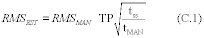 Appendix
D to Addendum to Method 320 - Estimating Minimum Concentration
Measurement Uncertainties (MAU and MIU) D.1 General
Appendix
D to Addendum to Method 320 - Estimating Minimum Concentration
Measurement Uncertainties (MAU and MIU) D.1 General
Estimate the minimum concentration measurement uncertainties for the i th analyte (MAUi) and j th interferant (MIUj) based on the spectral data in the m th analytical region by comparing the analyte band area in the analytical region (AAIim) and estimating or measuring the noise level of the system (RMSEST or RMSSM).
Note:For a single analytical region, the MAU or MIU value is the concentration of the analyte or interferant for which the band area is equal to the product of the analytical region width (in wavenumbers) and the noise level of the system (in absorbance units). If data from more than one analytical region are used in the determination of an analyte concentration, the MAU or MIU is the mean of the separate MAU or MIU values calculated for each analytical region.
D.2 CalculationsD.2.1 For each analytical region, set RMS = RMSSM if measured (appendix G of this addendum), or set RMS = RMSEST if estimated (appendix C of this addendum).
D.2.2 For each analyte associated with the analytical region, calculate MAUim using equation D.1,
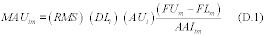
D.2.3 If only the m th analytical region is used to calculate the concentration of the i th analyte, set MAUi = MAUim.
D.2.4 If more than one analytical region is used to calculate the concentration of the i th analyte, set MAUi equal to the weighted mean of the appropriate MAUim values calculated above; the weight for each term in the mean is equal to the fraction of the total wavenumber range used for the calculation represented by each analytical region. Mathematically, if the set of analytical regions employed is [m′], then the MAU for each analytical region is given by equation D.2.
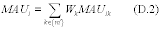 where the
weight Wik is defined for each term in the sum as
where the
weight Wik is defined for each term in the sum as 
D.2.5 Repeat sections D.2.1 through D.2.4 of this appendix to calculate the analogous values MIUj for the interferants j = 1 to J. Replace the value (AUi) (DLi) in equation D.1 with CPOTj/20; replace the value AAIim in equation D.1 with IAIjm.
Appendix E to Addendum to Method 320 - Determining Fractional Reproducibility Uncertainties (FRU) E.1 GeneralTo estimate the reproducibility of the spectroscopic results of the system, compare the CTS spectra recorded before and after preparing the reference spectra. Compare the difference between the spectra to their average band area. Perform the calculation for each analytical region on the portions of the CTS spectra associated with that analytical region.
E.2 CalculationsE.2.1 The CTS spectra {R1} consist of N spectra, denoted by S1i, i = 1, N. Similarly, the CTS spectra {R2} consist of N spectra, denoted by S2i, i = 1, N. Each Ski is the spectrum of a single compound, where i denotes the compound and k denotes the set {} of which Ski is a member. Form the spectra S3 according to S3i = S2i−S1i for each i. Form the spectra S4 according to S4i = [S2i + S1i]/2 for each i.
E.2.2 Each analytical region m is associated with a portion of the CTS spectra S2i and S1i, for a particular i, with lower and upper wavenumber limits FFLm and FFUm, respectively.
E.2.3 For each m and the associated i, calculate the band area of S4i in the wavenumber range FFUm to FFLm. Follow the guidelines of section B.1.2 of this addendum for this band area calculation. Denote the result by BAVm.
E.2.4 For each m and the associated i, calculate the RMSD of S3i between the absorbance values and their mean in the wavenumber range FFUm to FFLm. Denote the result by SRMSm.
E.2.5 For each analytical region m, calculate FMm using equation E.1,

E.2.6 If only the m th analytical region is used to calculate the concentration of the i th analyte, set FRUi = FMm.
E.2.7 If a number pi of analytical regions are used to calculate the concentration of the i th analyte, set FRUi equal to the weighted mean of the appropriate FMm values calculated according to section E.2.5. Mathematically, if the set of analytical regions employed is {m′}, then FRUi is given by equation E.2,
 where the
Wik are calculated as described in appendix D of this addendum.
Appendix F of Addendum to Method 320 - Determining Fractional
Calibration Uncertainties (FCU) F.1 General
where the
Wik are calculated as described in appendix D of this addendum.
Appendix F of Addendum to Method 320 - Determining Fractional
Calibration Uncertainties (FCU) F.1 General
F.1.1 The concentrations yielded by the computerized analytical program applied to each single-compound reference spectrum are defined as the indicated standard concentrations (ISC's). The ISC values for a single compound spectrum should ideally equal the accepted standard concentration (ASC) for one analyte or interferant, and should ideally be zero for all other compounds. Variations from these results are caused by errors in the ASC values, variations from the Beer's law (or modified Beer's law) model used to determine the concentrations, and noise in the spectra. When the first two effects dominate, the systematic nature of the errors is often apparent and the analyst shall take steps to correct them.
F.1.2 When the calibration error appears non-systematic, apply the procedures of sections F.2.1 through F.2.3 of this appendix to estimate the fractional calibration uncertainty (FCU) for each compound. The FCU is defined as the mean fractional error between the ASC and the ISC for all reference spectra with non-zero ASC for that compound. The FCU for each compound shall be less than the required fractional uncertainty specified in section 4.1 of this addendum.
F.1.3 The computerized analytical programs shall also be required to yield acceptably low concentrations for compounds with ISC = 0 when applied to the reference spectra. The ISC of each reference spectrum for each analyte or interferant shall not exceed that compound's minimum measurement uncertainty (MAU or MIU).
F.2 CalculationsF.2.1 Apply each analytical program to each reference spectrum. Prepare a similar table to that in Figure F.1 to present the ISC and ASC values for each analyte and interferant in each reference spectrum. Maintain the order of reference file names and compounds employed in preparing Figure F.1.
F.2.2 For all reference spectra in Figure F.1, verify that the absolute values of the ISC's are less than the compound's MAU (for analytes) or MIU (for interferants).
F.2.3 For each analyte reference spectrum, calculate the quantity (ASC-ISC)/ASC. For each analyte, calculate the mean of these values (the FCUi for the i th analyte) over all reference spectra. Prepare a similar table to that in Figure F.2 to present the FCUi and analytical uncertainty limit (AUi) for each analyte.
Figure F.1 - Presentation of Accepted Standard Concentrations (ASC's) and Indicated Standard Concentrations (ISC's)
| Compound name | Reference spectrum file name | ASC (ppm) | ISC (ppm) | |||||
| Analytes Interferants | ||||||||
| i = 1 I | ||||||||
| j = 1 J | ||||||||
Figure F.2 - Presentation of Fractional Calibration Uncertainties (FCU's) and Analytical Uncertainties (AU's)
| Analyte name | FCU (%) | AU (%) |
|---|---|---|
The root-mean-square (RMS) noise level is the standard measure of noise. The RMS noise level of a contiguous segment of a spectrum is the RMSD between the absorbance values that form the segment and the mean value of the segment (see appendix A of this addendum).
G.2 CalculationsG.2.1 Evacuate the absorption cell or fill it with UPC grade nitrogen at approximately one atmosphere total pressure.
G.2.2 Record two single beam spectra of signal integration period tSS.
G.2.3 Form the double beam absorption spectrum from these two single beam spectra, and calculate the noise level RMSSm in the M analytical regions.
Appendix H of Addendum to Method 320 - Determining Sample Absorption Pathlength (LS) and Fractional Analytical Uncertainty (FAU) H.1 GeneralReference spectra recorded at absorption pathlength (LR), gas pressure (PR), and gas absolute temperature (TR) may be used to determine analyte concentrations in samples whose spectra are recorded at conditions different from that of the reference spectra, i.e., at absorption pathlength (LS), absolute temperature (TS), and pressure (PS). This appendix describes the calculations for estimating the fractional uncertainty (FAU) of this practice. It also describes the calculations for determining the sample absorption pathlength from comparison of CTS spectra, and for preparing spectra for further instrumental and procedural checks.
H.1.1 Before sampling, determine the sample absorption pathlength using least squares analysis. Determine the ratio LS/LR by comparing the spectral sets {R1} and {R3}, which are recorded using the same CTS at LS and LR, and TS and TR, but both at PR.
H.1.2 Determine the fractional analysis uncertainty (FAU) for each analyte by comparing a scaled CTS spectral set, recorded at LS, TS, and PS, to the CTS reference spectra of the same gas, recorded at LR, TR, and PR. Perform the quantitative comparison after recording the sample spectra, based on band areas of the spectra in the CTS absorbance band associated with each analyte.
H.2 CalculationsH.2.1 Absorption Pathlength Determination. Perform and document separate linear baseline corrections to each analytical region in the spectral sets {R1} and {R3}. Form a one-dimensional array AR containing the absorbance values from all segments of {R1} that are associated with the analytical regions; the members of the array are ARi, i = 1, n. Form a similar one-dimensional array AS from the absorbance values in the spectral set {R3}; the members of the array are ASi, i = 1, n. Based on the model AS = rAR + E, determine the least-squares estimate of r, the value of r which minimizes the square error E 2. Calculate the sample absorption pathlength, LS, using equation H.1,
H.2.2 Fractional Analysis Uncertainty. Perform and document separate linear baseline corrections to each analytical region in the spectral sets {R1} and {R4}. Form the arrays AS and AR as described in section H.2.1 of this appendix, using values from {R1} to form AR, and values from {R4} to form AS. Calculate NRMSE and IAAV using equations H.2 and H.3,
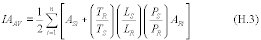
The fractional analytical uncertainty, FAU, is given by equation H.4,
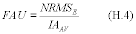 Appendix
I to Addendum to Method 320 - Determining Fractional Model
Uncertainties (FMU) I.1 General
Appendix
I to Addendum to Method 320 - Determining Fractional Model
Uncertainties (FMU) I.1 General
To prepare analytical programs for FTIR analyses, the sample constituents must first be assumed. The calculations in this appendix, based upon a simulation of the sample spectrum, shall be used to verify the appropriateness of these assumptions. The simulated spectra consist of the sum of single compound reference spectra scaled to represent their contributions to the sample absorbance spectrum; scaling factors are based on the indicated standard concentrations (ISC) and measured (sample) analyte and interferant concentrations, the sample and reference absorption pathlengths, and the sample and reference gas pressures. No band-shape correction for differences in the temperature of the sample and reference spectra gases is made; such errors are included in the FMU estimate. The actual and simulated sample spectra are quantitatively compared to determine the fractional model uncertainty; this comparison uses the reference spectra band areas and residuals in the difference spectrum formed from the actual and simulated sample spectra.
I.2 CalculationsI.2.1 For each analyte (with scaled concentration RSAi), select a reference spectrum SAi with indicated standard concentration ISCi. Calculate the scaling factors, RAi, using equation I.1,
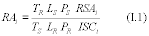 Form the
spectra SACi by scaling each SAi by the factor RAi.
Form the
spectra SACi by scaling each SAi by the factor RAi.
I.2.2 For each interferant, select a reference spectrum SIk with indicated standard concentration ISCk. Calculate the scaling factors, RIk, using equation I.2,
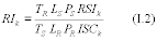 Form the
spectra SICk by scaling each SIk by the factor RIk.
Form the
spectra SICk by scaling each SIk by the factor RIk.
I.2.3 For each analytical region, determine by visual inspection which of the spectra SACi and SICk exhibit absorbance bands within the analytical region. Subtract each spectrum SACi and SICk exhibiting absorbance from the sample spectrum SS to form the spectrum SUBS. To save analysis time and to avoid the introduction of unwanted noise into the subtracted spectrum, it is recommended that the calculation be made (1) only for those spectral data points within the analytical regions, and (2) for each analytical region separately using the original spectrum SS.
I.2.4 For each analytical region m, calculate the RMSD of SUBS between the absorbance values and their mean in the region FFUm to FFLm. Denote the result by RMSSm.
I.2.5 For each analyte i, calculate FMm, using equation I.3,
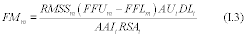 for each
analytical region associated with the analyte.
for each
analytical region associated with the analyte.
I.2.6 If only the m th analytical region is used to calculate the concentration of the i th analyte, set FMUi = FMm.
I.2.7 If a number of analytical regions are used to calculate the concentration of the i th analyte, set FMi equal to the weighted mean of the appropriate FMm values calculated using equation I-3. Mathematically, if the set of analytical regions employed is {m′}, then the fractional model uncertainty, FMU, is given by equation I.4,
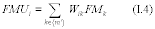 where Wik
is calculated as described in appendix D of this addendum. Appendix
J of Addendum to Method 320 - Determining Overall Concentration
Uncertainties (OCU)
where Wik
is calculated as described in appendix D of this addendum. Appendix
J of Addendum to Method 320 - Determining Overall Concentration
Uncertainties (OCU)
The calculations in this addendum estimate the measurement uncertainties for various FTIR measurements. The lowest possible overall concentration uncertainty (OCU) for an analyte is its MAU value, which is an estimate of the absolute concentration uncertainty when spectral noise dominates the measurement error. However, if the product of the largest fractional concentration uncertainty (FRU, FCU, FAU, or FMU) and the measured concentration of an analyte exceeds the MAU for the analyte, then the OCU is this product. In mathematical terms, set OFUi = MAX{FRUi, FCUi, FAUi, FMUi} and OCUi = MAX{RSAi*OFUi, MAUi}.
Test Method 321 - Measurement of Gaseous Hydrogen Chloride Emissions At Portland Cement Kilns by Fourier Transform Infrared (FTIR) Spectroscopy 1.0 IntroductionThis method should be performed by those persons familiar with the operation of Fourier Transform Infrared (FTIR) instrumentation in the application to source sampling. This document describes the sampling procedures for use in the application of FTIR spectrometry for the determination of vapor phase hydrogen chloride (HCl) concentrations both before and after particulate matter control devices installed at portland cement kilns. A procedure for analyte spiking is included for quality assurance. This method is considered to be self validating provided that the requirements listed in section 9 of this method are followed. The analytical procedures for interpreting infrared spectra from emission measurements are described in the “Protocol For The Use of Extractive Fourier Transform Infrared (FTIR) Spectrometry in Analyses of Gaseous Emissions From Stationary Industrial Sources”, included as an addendum to proposed Method 320 of this appendix (hereafter referred to as the “FTIR Protocol)”. References 1 and 2 describe the use of FTIR spectrometry in field measurements. Sample transport presents the principal difficulty in directly measuring HCl emissions. This identical problem must be overcome by any extractive measurement method. HCl is reactive and water soluble. The sampling system must be adequately designed to prevent sample condensation in the system.
1.1 Scope and Application
This method is specifically designed for the application of FTIR Spectrometry in extractive measurements of gaseous HCl concentrations in portland cement kiln emissions.
1.2 ApplicabilityThis method applies to the measurement of HCl [CAS No. 7647-01-0]. This method can be applied to the determination of HCl concentrations both before and after particulate matter control devices installed at portland cement manufacturing facilities. This method applies to either continuous flow through measurement (with isolated sample analysis) or grab sampling (batch analysis). HCl is measured using the mid-infrared spectral region for analysis (about 400 to 4000 cm−1 or 25 to 2.5 µm). Table 1 lists the suggested analytical region for quantification of HCl taking the interference from water vapor into consideration.
Table 1 - Example Analytical Region for HCl
| Compound | Analytical region (cm−1) |
Potential interferants |
|---|---|---|
| Hydrogen chloride | 2679-2840 | Water. |
1.3 Method Range and Sensitivity
1.3.1 The analytical range is determined by the instrumental design and the composition of the gas stream. For practical purposes there is no upper limit to the range because the pathlength may be reduced or the sample may be diluted. The lower detection range depends on (1) the absorption coefficient of the compound in the analytical frequency region, (2) the spectral resolution, (3) the interferometer sampling time, (4) the detector sensitivity and response, and (5) the absorption pathlength.
1.3.2 The practical lower quantification range is usually higher than that indicated by the instrument performance in the laboratory, and is dependent upon (1) the presence of interfering species in the exhaust gas (notably H2O), (2) the optical alignment of the gas cell and transfer optics, and (3) the quality of the reflective surfaces in the cell (cell throughput). Under typical test conditions (moisture content of up to 30 percent, 10 meter absorption path length, liquid nitrogen-cooled IR detector, 0.5 cm−1 resolution, and an interferometer sampling time of 60 seconds) a typical lower quantification range for HCl is 0.1 to 1.0 ppm.
1.4 Data Quality Objectives
1.4.1 In designing or configuring the analytical system, data quality is determined by measuring of the root mean square deviation (RMSD) of the absorbance values within a chosen spectral (analytical) region. The RMSD provides an indication of the signal-to-noise ratio (S/N) of the spectral baseline. Appendix D of the FTIR Protocol (the addendum to Method 320 of this appendix) presents a discussion of the relationship between the RMSD, lower detection limit, DLi, and analytical uncertainty, AUi. It is important to consider the target analyte quantification limit when performing testing with FTIR instrumentation, and to optimize the system to achieve the desired detection limit.
1.4.2 Data quality is determined by measuring the root mean square (RMS) noise level in each analytical spectral region (appendix C of the FTIR Protocol). The RMS noise is defined as the root mean square deviation (RMSD) of the absorbance values in an analytical region from the mean absorbance value in the same region. Appendix D of the FTIR Protocol defines the minimum analyte uncertainty (MAU), and how the RMSD is used to calculate the MAU. The MAUim is the minimum concentration of the ith analyte in the mth analytical region for which the analytical uncertainty limit can be maintained. Table 2 presents example values of AU and MAU using the analytical region presented in Table 1.
Table 2 - Example Pre-Test Protocol Calculations for Hydrogen Chloride
| HCl | |
|---|---|
| Reference concentration (ppm-meters)/K | 11.2 |
| Reference Band area | 2.881 |
| DL (ppm-meters)/K | 0.1117 |
| AU | 0.2 |
| CL (DL × AU) | 0.02234 |
| FL (cm−1) | 2679.83 |
| FU (cm−1) | 2840.93 |
| FC (cm−1) | 2760.38 |
| AAI (ppm-meters)/K | 0.06435 |
| RMSD | 2.28E-03 |
| MAU (ppm-meters)/K | 1.28E-01 |
| MAU ppm at 22 meters and 250 °F | .0.2284 |
2.1 Principle
See Method 320 of this appendix. HCl can also undergo rotation transitions by absorbing energy in the far-infrared spectral region. The rotational transitions are superimposed on the vibrational fundamental to give a series of lines centered at the fundamental vibrational frequency, 2885 cm- 1. The frequencies of absorbance and the pattern of rotational/vibrational lines are unique to HCl. When this distinct pattern is observed in an infrared spectrum of an unknown sample, it unequivocally identifies HCl as a component of the mixture. The infrared spectrum of HCl is very distinctive and cannot be confused with the spectrum of any other compound. See Reference 6.
2.2 Sampling and Analysis. See Method 320 of this appendix.
2.3 Operator Requirements. The analyst must have knowledge of spectral patterns to choose an appropriate absorption path length or determine if sample dilution is necessary. The analyst should also understand FTIR instrument operation well enough to choose instrument settings that are consistent with the objectives of the analysis.
3.0 DefinitionsSee appendix A of the FTIR Protocol.
4.0 InterferencesThis method will not measure HCl under conditions: (1) where the sample gas stream can condense in the sampling system or the instrumentation, or (2) where a high moisture content sample relative to the analyte concentrations imparts spectral interference due to the water vapor absorbance bands. For measuring HCl the first (sampling) consideration is more critical. Spectral interference from water vapor is not a significant problem except at very high moisture levels and low HCl concentrations.
4.1 Analytical Interferences. See Method 320 of this appendix.
4.1.1 Background Interferences. See Method 320 of this appendix.
4.1.2 Spectral interferences. Water vapor can present spectral interference for FTIR gas analysis of HCl. Therefore, the water vapor in the spectra of kiln gas samples must be accounted for. This means preparing at least one spectrum of a water vapor sample where the moisture concentration is close to that in the kiln gas.
4.2 Sampling System Interferences. The principal sampling system interferant for measuring HCl is water vapor. Steps must be taken to ensure that no condensation forms anywhere in the probe assembly, sample lines, or analytical instrumentation. Cold spots anywhere in the sampling system must be avoided. The extent of sampling system bias in the FTIR analysis of HCl depends on concentrations of potential interferants, moisture content of the gas stream, temperature of the gas stream, temperature of sampling system components, sample flow rate, and reactivity of HCl with other species in the gas stream (e.g., ammonia). For measuring HCl in a wet gas stream the temperatures of the gas stream, sampling components, and the sample flow rate are of primary importance. Analyte spiking with HCl is performed to demonstrate the integrity of the sampling system for transporting HCl vapor in the flue gas to the FTIR instrument. See section 9 of this method for a complete description of analyte spiking.
5.0 Safety5.1 Hydrogen chloride vapor is corrosive and can cause irritation or severe damage to respiratory system, eyes and skin. Exposure to this compound should be avoided.
5.2 This method may involve sampling at locations having high positive or negative pressures, or high concentrations of hazardous or toxic pollutants, and can not address all safety problems encountered under these diverse sampling conditions. It is the responsibility of the tester(s) to ensure proper safety and health practices, and to determine the applicability of regulatory limitations before performing this test method. Leak-check procedures are outlined in section 8.2 of Method 320 of this appendix.
6.0 Equipment and Supplies Note:Mention of trade names or specific products does not constitute endorsement by the Environmental Protection Agency.
6.1 FTIR Spectrometer and Detector. An FTIR Spectrometer system (interferometer, transfer optics, gas cell and detector) having the capability of measuring HCl to the predetermined minimum detectable level required (see section 4.1.3 of the FTIR Protocol). The system must also include an accurate means to control and/or measure the temperature of the FTIR gas analysis cell, and a personal computer with compatible software that provides real-time updates of the spectral profile during sample and spectral collection.
6.2 Pump. Capable of evacuating the FTIR cell volume to 1 Torr (133.3 Pascals) within two minutes (for batch sample analysis).
6.3 Mass Flow Meters/Controllers. To accurately measure analyte spike flow rate, having the appropriate calibrated range and a stated accuracy of ±2 percent of the absolute measurement value. This device must be calibrated with the major component of the calibration/spike gas (e.g., nitrogen) using an NIST traceable bubble meter or equivalent. Single point calibration checks should be performed daily in the field. When spiking HCl, the mass flow meter/controller should be thoroughly purged before and after introduction of the gas to prevent corrosion of the interior parts.
6.4 Polytetrafluoroethane tubing. Diameter and length suitable to connect cylinder regulators.
6.5 Stainless Steel tubing. Type 316 of appropriate length and diameter for heated connections.
6.6 Gas Regulators. Purgeable HCl regulator.
6.7 Pressure Gauge. Capable of measuring pressure from 0 to 1000 Torr (133.3 Pa = 1 Torr) within ±5 percent.
6.8 Sampling Probe. Glass, stainless steel or other appropriate material of sufficient length and physical integrity to sustain heating, prevent adsorption of analytes and capable of reaching gas sampling point.
6.9 Sampling Line. Heated 180 °C (360 °F) and fabricated of either stainless steel, polytetrafluoroethane or other material that prevents adsorption of HCl and transports effluent to analytical instrumentation. The extractive sample line must have the capability to transport sample gas to the analytical components as well as direct heated calibration spike gas to the calibration assembly located at the sample probe. It is important to minimize the length of heated sample line.
6.10 Particulate Filters. A sintered stainless steel filter rated at 20 microns or greater may be placed at the inlet of the probe (for removal of large particulate matter). A heated filter (Balston or equivalent) rated at 1 micron is necessary for primary particulate matter removal, and shall be placed immediately after the heated probe. The filter/filter holder temperature should be maintained at 180 °C (360 °F).
6.11 Calibration/Analyte Spike Assembly. A heated three-way valve assembly (or equivalent) to introduce surrogate spikes into the sampling system at the outlet of the probe before the primary particulate filter.
6.12 Sample Extraction Pump. A leak-free heated head pump (KNF Neuberger or equivalent) capable of extracting sample effluent through entire sampling system at a rate which prevents analyte losses and minimizes analyzer response time. The pump should have a heated by-pass and may be placed either before the FTIR instrument or after. If the sample pump is located upstream of the FTIR instrument, it must be fabricated from materials non-reactive to HCl. The sampling system and FTIR measurement system shall allow the operator to obtain at least six sample spectra during a one-hour period.
6.13 Barometer. For measurement of barometric pressure.
6.14 Gas Sample Manifold. A distribution manifold having the capabilities listed in sections 6.14.1 through 6.14.4;
6.14.1 Delivery of calibration gas directly to the analytical instrumentation;
6.14.2 Delivery of calibration gas to the sample probe (system calibration or analyte spike) via a heated traced sample line;
6.14.3 Delivery of sample gas (kiln gas, spiked kiln gas, or system calibrations) to the analytical instrumentation;
6.14.4 Delivery (optional) of a humidified nitrogen sample stream.
6.15 Flow Measurement Device. Type S Pitot tube (or equivalent) and Magnahelic set for measurement of volumetric flow rate.
7.0 Reagents and StandardsHCl can be purchased in a standard compressed gas cylinder. The most stable HCl cylinder mixture available has a concentration certified at ±5 percent. Such a cylinder is suitable for performing analyte spiking because it will provide reproducible samples. The stability of the cylinder can be monitored over time by periodically performing direct FTIR analysis of cylinder samples. It is recommended that a 10-50 ppm cylinder of HCl be prepared having from 2-5 ppm SF6 as a tracer compound. (See sections 7.1 through 7.3 of Method 320 of this appendix for a complete description of the use of existing HCl reference spectra. See section 9.1 of Method 320 of this appendix for a complete discussion of standard concentration selection.)
8.0 Sample Collection, Preservation and StorageSee also Method 320 of this appendix.
8.1 Pretest. A screening test is ideal for obtaining proper data that can be used for preparing analytical program files. Information from literature surveys and source personnel is also acceptable. Information about the sampling location and gas stream composition is required to determine the optimum sampling system configuration for measuring HCl. Determine the percent moisture of the kiln gas by Method 4 of appendix A to part 60 of this chapter or by performing a wet bulb/dry bulb measurement. Perform a preliminary traverse of the sample duct or stack and select the sampling point(s). Acquire an initial spectrum and determine the optimum operational pathlength of the instrument.
8.2 Leak-Check. See Method 320 of this appendix, section 8.2 for direction on performing leak-checks.
8.3 Background Spectrum. See Method 320 of this appendix, section 8.5 for direction in background spectral acquisition.
8.4 Pre-Test Calibration Transfer Standard (Direct Instrument Calibration). See Method 320 of this appendix, section 8.3 for direction in CTS spectral acquisition.
8.5 Pre-Test System Calibration. See Method 320 of this appendix, sections 8.6.1 through 8.6.2 for direction in performing system calibration.
8.6 Sampling
8.6.1 Extractive System. An extractive system maintained at 180 °C (360 °F) or higher which is capable of directing a total flow of at least 12 L/min to the sample cell is required (References 1 and 2). Insert the probe into the duct or stack at a point representing the average volumetric flow rate and 25 percent of the cross sectional area. Co-locate an appropriate flow monitoring device with the sample probe so that the flow rate is recorded at specified time intervals during emission testing (e.g., differential pressure measurements taken every 10 minutes during each run).
8.6.2 Batch Samples. Evacuate the absorbance cell to 5 Torr (or less) absolute pressure before taking first sample. Fill the cell with kiln gas to ambient pressure and record the infrared spectrum, then evacuate the cell until there is no further evidence of infrared absorption. Repeat this procedure, collecting a total of six separate sample spectra within a 1-hour period.
8.6.3 Continuous Flow Through Sampling. Purge the FTIR cell with kiln gas for a time period sufficient to equilibrate the entire sampling system and FTIR gas cell. The time required is a function of the mechanical response time of the system (determined by performing the system calibration with the CTS gas or equivalent), and by the chemical reactivity of the target analytes. If the effluent target analyte concentration is not variable, observation of the spectral up-date of the flowing gas sample should be performed until equilibration of the sample is achieved. Isolate the gas cell from the sample flow by directing the purge flow to vent. Record the spectrum and pressure of the sample gas. After spectral acquisition, allow the sample gas to purge the cell with at least three volumes of kiln gas. The time required to adequately purge the cell with the required volume of gas is a function of (1) cell volume, (2) flow rate through the cell, and (3) cell design. It is important that the gas introduction and vent for the FTIR cell provides a complete purge through the cell.
8.6.4 Continuous Sampling. In some cases it is possible to collect spectra continuously while the FTIR cell is purged with sample gas. The sample integration time, tss, the sample flow rate through the gas cell, and the sample integration time must be chosen so that the collected data consist of at least 10 spectra with each spectrum being of a separate cell volume of flue gas. Sampling in this manner may only be performed if the native source analyte concentrations do not affect the test results.
8.7 Sample Conditioning
8.7.1 High Moisture Sampling. Kiln gas emitted from wet process cement kilns may contain 3- to 40 percent moisture. Zinc selenide windows or the equivalent should be used when attempting to analyze hot/wet kiln gas under these conditions to prevent dissolution of water soluble window materials (e.g., KBr).
8.7.2 Sample Dilution. The sample may be diluted using an in-stack dilution probe, or an external dilution device provided that the sample is not diluted below the instrument's quantification range. As an alternative to using a dilution probe, nitrogen may be dynamically spiked into the effluent stream in the same manner as analyte spiking. A constant dilution rate shall be maintained throughout the measurement process. It is critical to measure and verify the exact dilution ratio when using a dilution probe or the nitrogen spiking approach. Calibrating the system with a calibration gas containing an appropriate tracer compound will allow determination of the dilution ratio for most measurement systems. The tester shall specify the procedures used to determine the dilution ratio, and include these calibration results in the report.
8.8 Sampling QA, Data Storage and Reporting. See the FTIR Protocol. Sample integration times shall be sufficient to achieve the required signal-to-noise ratio, and all sample spectra should have unique file names. Two copies of sample interferograms and processed spectra will be stored on separate computer media. For each sample spectrum the analyst must document the sampling conditions, the sampling time (while the cell was being filled), the time the spectrum was recorded, the instrumental conditions (path length, temperature, pressure, resolution, integration time), and the spectral file name. A hard copy of these data must be maintained until the test results are accepted.
8.9 Signal Transmittance. Monitor the signal transmittance through the instrumental system. If signal transmittance (relative to the background) drops below 95 percent in any spectral region where the sample does not absorb infrared energy, then a new background spectrum must be obtained.
8.10 Post-test CTS. After the sampling run completion, record the CTS spectrum. Analysis of the spectral band area used for quantification from pre- and post-test CTS spectra should agree to within ±5 percent or corrective action must be taken.
8.11 Post-test QA. The sample spectra shall be inspected immediately after the run to verify that the gas matrix composition was close to the assumed gas matrix, (this is necessary to account for the concentrations of the interferants for use in the analytical analysis programs), and to confirm that the sampling and instrumental parameters were appropriate for the conditions encountered.
9.0 Quality ControlUse analyte spiking to verify the effectiveness of the sampling system for the target compounds in the actual kiln gas matrix. QA spiking shall be performed before and after each sample run. QA spiking shall be performed after the pre- and post-test CTS direct and system calibrations. The system biases calculated from the pre- and post-test dynamic analyte spiking shall be within ±30 percent for the spiked surrogate analytes for the measurements to be considered valid. See sections 9.3.1 through 9.3.2 for the requisite calculations. Measurement of the undiluted spike (direct-to-cell measurement) involves sending dry, spike gas to the FTIR cell, filling the cell to 1 atmosphere and obtaining the spectrum of this sample. The direct-to-cell measurement should be performed before each analyte spike so that the recovery of the dynamically spiked analytes may be calculated. Analyte spiking is only effective for assessing the integrity of the sampling system when the concentration of HCl in the source does not vary substantially. Any attempt to quantify an analyte recovery in a variable concentration matrix will result in errors in the expected concentration of the spiked sample. If the kiln gas target analyte concentrations vary by more than ±5 percent (or 5 ppm, whichever is greater) in the time required to acquire a sample spectrum, it may be necessary to: (1) Use a dual sample probe approach, (2) use two independent FTIR measurement systems, (3) use alternate QA/QC procedures, or (4) postpone testing until stable emission concentrations are achieved. (See section 9.2.3 of this method). It is recommended that a laboratory evaluation be performed before attempting to employ this method under actual field conditions. The laboratory evaluation shall include (1) performance of all applicable calculations in section 4 of the FTIR Protocol; (2) simulated analyte spiking experiments in dry (ambient) and humidified sample matrices using HCl; and (3) performance of bias (recovery) calculations from analyte spiking experiments. It is not necessary to perform a laboratory evaluation before every field test. The purpose of the laboratory study is to demonstrate that the actual instrument and sampling system configuration used in field testing meets the requirements set forth in this method.
9.1 Spike Materials. Perform analyte spiking with an HCl standard to demonstrate the integrity of the sampling system.
9.1.1 An HCl standard of approximately 50 ppm in a balance of ultra pure nitrogen is recommended. The SF6 (tracer) concentration shall be 2 to 5 ppm depending upon the measurement pathlength. The spike ratio (spike flow/total flow) shall be no greater than 1:10, and an ideal spike concentration should approximate the native effluent concentration.
9.1.2 The ideal spike concentration may not be achieved because the target concentration cannot be accurately predicted prior to the field test, and limited calibration standards will be available during testing. Therefore, practical constraints must be applied that allow the tester to spike at an anticipated concentration. For these tests, the analyte concentration contributed by the HCl standard spike should be 1 to 5 ppm or should more closely approximate the native concentration if it is greater.
9.2 Spike Procedure
9.2.1 A spiking/sampling apparatus is shown in Figure 2. Introduce the spike/tracer gas mixture at a constant flow (±2 percent) rate at approximately 10 percent of the total sample flow. (For example, introduce the surrogate spike at 1 L/min 20 cc/min, into a total sample flow rate of 10 L/min). The spike must be pre-heated before introduction into the sample matrix to prevent a localized condensation of the gas stream at the spike introduction point. A heated sample transport line(s) containing multiple transport tubes within the heated bundle may be used to spike gas up through the sampling system to the spike introduction point. Use a calibrated flow device (e.g., mass flow meter/controller), to monitor the spike flow as indicated by a calibrated flow meter or controller, or alternately, the SF6 tracer ratio may be calculated from the direct measurement and the diluted measurement. It is often desirable to use the tracer approach in calculating the spike/total flow ratio because of the difficulty in accurately measuring hot/wet total flow. The tracer technique has been successfully used in past validation efforts (Reference 1).
9.2.2 Perform a direct-to-cell measurement of the dry, undiluted spike gas. Introduce the spike directly to the FTIR cell, bypassing the sampling system. Fill cell to 1 atmosphere and collect the spectrum of this sample. Ensure that the spike gas has equilibrated to the temperature of the measurement cell before acquisition of the spectra. Inspect the spectrum and verify that the gas is dry and contains negligible CO2. Repeat the process to obtain a second direct-to-cell measurement. Analysis of spectral band areas for HCl from these duplicate measurements should agree to within ±5 percent of the mean.
9.2.3 Analyte Spiking. Determine whether the kiln gas contains native concentrations of HCl by examination of preliminary spectra. Determine whether the concentration varies significantly with time by observing a continuously up-dated spectrum of sample gas in the flow-through sampling mode. If the concentration varies by more than ±5 percent during the period of time required to acquire a spectra, then an alternate approach should be used. One alternate approach uses two sampling lines to convey sample to the gas distribution manifold. One of the sample lines is used to continuously extract unspiked kiln gas from the source. The other sample line serves as the analyte spike line. One FTIR system can be used in this arrangement. Spiked or unspiked sample gas may be directed to the FTIR system from the gas distribution manifold, with the need to purge only the components between the manifold and the FTIR system. This approach minimizes the time required to acquire an equilibrated sample of spiked or unspiked kiln gas. If the source varies by more than ±5 percent (or 5 ppm, whichever is greater) in the time it takes to switch from the unspiked sample line to the spiked sample line, then analyte spiking may not be a feasible means to determine the effectiveness of the sampling system for the HCl in the sample matrix. A second alternative is to use two completely independent FTIR measurement systems. One system would measure unspiked samples while the other system would measure the spiked samples. As a last option, (where no other alternatives can be used) a humidified nitrogen stream may be generated in the field which approximates the moisture content of the kiln gas. Analyte spiking into this humidified stream can be employed to assure that the sampling system is adequate for transporting the HCl to the FTIR instrumentation.
9.2.3.1 Adjust the spike flow rate to approximately 10 percent of the total flow by metering spike gas through a calibrated mass flowmeter or controller. Allow spike flow to equilibrate within the sampling system before analyzing the first spiked kiln gas samples. A minimum of two consecutive spikes are required. Analysis of the spectral band area used for quantification should agree to within ±5 percent or corrective action must be taken.
9.2.3.2 After QA spiking is completed, the sampling system components shall be purged with nitrogen or dry air to eliminate traces of the HCl compound from the sampling system components. Acquire a sample spectra of the nitrogen purge to verify the absence of the calibration mixture.
9.2.3.3 Analyte spiking procedures must be carefully executed to ensure that meaningful measurements are achieved. The requirements of sections 9.2.3.3.1 through 9.2.3.3.4 shall be met.
9.2.3.3.1 The spike must be in the vapor phase, dry, and heated to (or above) the kiln gas temperature before it is introduced to the kiln gas stream.
9.2.3.3.2 The spike flow rate must be constant and accurately measured.
9.2.3.3.3 The total flow must also be measured continuously and reliably or the dilution ratio must otherwise be verified before and after a run by introducing a spike of a non-reactive, stable compound (i.e., tracer).
9.2.3.3.4 The tracer must be inert to the sampling system components, not contained in the effluent gas, and readily detected by the analytical instrumentation. Sulfur hexafluoride (SF6) has been used successfully (References 1 and 2) for this purpose.
9.3 Calculations
9.3.1 Recovery. Calculate the percent recovery of the spiked analytes using equations 1 and 2.
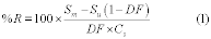 Sm = Mean
concentration of the analyte spiked effluent samples (observed).
Sm = Mean
concentration of the analyte spiked effluent samples (observed).
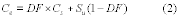 Ce =
Expected concentration of the spiked samples (theoretical). DF =
Dilution Factor (Total flow/Spike flow). Total flow = spike flow
plus effluent flow. Cs = cylinder concentration of spike gas. Su =
native concentration of analytes in unspiked samples. The spike
dilution factor may be confirmed by measuring the total flow and
the spike flow directly. Alternately, the spike dilution can be
verified by comparing the concentration of the tracer compound in
the spiked samples (diluted) to the tracer concentration in the
direct (undiluted) measurement of the spike gas. If SF6 is the
tracer gas, then
Ce =
Expected concentration of the spiked samples (theoretical). DF =
Dilution Factor (Total flow/Spike flow). Total flow = spike flow
plus effluent flow. Cs = cylinder concentration of spike gas. Su =
native concentration of analytes in unspiked samples. The spike
dilution factor may be confirmed by measuring the total flow and
the spike flow directly. Alternately, the spike dilution can be
verified by comparing the concentration of the tracer compound in
the spiked samples (diluted) to the tracer concentration in the
direct (undiluted) measurement of the spike gas. If SF6 is the
tracer gas, then  [SF6]spike = the
diluted SF6 concentration measured in a spiked sample. [SF6]direct
= the SF6 concentration measured directly.
[SF6]spike = the
diluted SF6 concentration measured in a spiked sample. [SF6]direct
= the SF6 concentration measured directly.
9.3.2 Bias. The bias may be determined by the difference between the observed spike value and the expected response (i.e., the equivalent concentration of the spiked material plus the analyte concentration adjusted for spike dilution). Bias is defined by section 6.3.1 of EPA Method 301 of this appendix (Reference 8) as,
 Where: B
= Bias at spike level. Sm = Mean concentration of the analyte
spiked samples. Ce = Expected concentration of the analyte in
spiked samples. Acceptable recoveries for analyte spiking are ±30
percent. Application of correction factors to the data based upon
bias and recovery calculations is subject to the approval of the
Administrator. 10.0 Calibration and Standardization
Where: B
= Bias at spike level. Sm = Mean concentration of the analyte
spiked samples. Ce = Expected concentration of the analyte in
spiked samples. Acceptable recoveries for analyte spiking are ±30
percent. Application of correction factors to the data based upon
bias and recovery calculations is subject to the approval of the
Administrator. 10.0 Calibration and Standardization
10.1 Calibration transfer standards (CTS). The EPA Traceability Protocol gases or NIST traceable standards, with a minimum accuracy of ±2 percent shall be used. For other requirements of the CTS, see the FTIR Protocol section 4.5.
10.2 Signal-to-Noise Ratio (S/N). The S/N shall be less than the minimum acceptable measurement uncertainty in the analytical regions to be used for measuring HCl.
10.3 Absorbance Pathlength. Verify the absorbance path length by comparing CTS spectra to reference spectra of the calibration gas(es).
10.4 Instrument Resolution. Measure the line width of appropriate CTS band(s) to verify instrumental resolution.
10.5 Apodization Function. Choose the appropriate apodization function. Determine any appropriate mathematical transformations that are required to correct instrumental errors by measuring the CTS. Any mathematical transformations must be documented and reproducible. Reference 9 provides additional information about FTIR instrumentation.
11.0 Analytical ProcedureA full description of the analytical procedures is given in sections 4.6-4.11, sections 5, 6, and 7, and the appendices of the FTIR Protocol. Additional description of quantitative spectral analysis is provided in References 10 and 11.
12.0 Data Analysis and CalculationsData analysis is performed using appropriate reference spectra whose concentrations can be verified using CTS spectra. Various analytical programs (References 10 and 11) are available to relate sample absorbance to a concentration standard. Calculated concentrations should be verified by analyzing spectral baselines after mathematically subtracting scaled reference spectra from the sample spectra. A full description of the data analysis and calculations may be found in the FTIR Protocol (sections 4.0, 5.0, 6.0 and appendices).
12.1 Calculated concentrations in sample spectra are corrected for differences in absorption pathlength between the reference and sample spectra by
 Where:
Ccorr = The pathlength corrected concentration. Ccalc = The initial
calculated concentration (output of the multicomponent analysis
program designed for the compound). Lr = The pathlength associated
with the reference spectra. Ls = The pathlength associated with the
sample spectra. Ts = The absolute temperature (K) of the sample
gas. Tr = The absolute temperature (K) at which reference spectra
were recorded.
Where:
Ccorr = The pathlength corrected concentration. Ccalc = The initial
calculated concentration (output of the multicomponent analysis
program designed for the compound). Lr = The pathlength associated
with the reference spectra. Ls = The pathlength associated with the
sample spectra. Ts = The absolute temperature (K) of the sample
gas. Tr = The absolute temperature (K) at which reference spectra
were recorded.
12.2 The temperature correction in equation 5 is a volumetric correction. It does not account for temperature dependence of rotational-vibrational relative line intensities. Whenever possible, the reference spectra used in the analysis should be collected at a temperature near the temperature of the FTIR cell used in the test to minimize the calculated error in the measurement (FTIR Protocol, appendix D). Additionally, the analytical region chosen for the analysis should be sufficiently broad to minimize errors caused by small differences in relative line intensities between reference spectra and the sample spectra.
13.0 Method PerformanceA description of the method performance may be found in the FTIR Protocol. This method is self validating provided the results meet the performance specification of the QA spike in sections 9.0 through 9.3 of this method.
14.0 Pollution PreventionThis is a gas phase measurement. Gas is extracted from the source, analyzed by the instrumentation, and discharged through the instrument vent.
15.0 Waste ManagementGas standards of HCl are handled according to the instructions enclosed with the material safety data sheet.
16.0 References1. “Laboratory and Field Evaluation of a Methodology for Determination of Hydrogen Chloride Emissions From Municipal and Hazardous Waste Incinerators,” S.C. Steinsberger and J.H. Margeson. Prepared for U.S. Environmental Protection Agency, Research Triangle Park, NC. NTIS Report No. PB89-220586. (1989).
2. “Evaluation of HCl Measurement Techniques at Municipal and Hazardous Waste Incinerators,” S.A. Shanklin, S.C. Steinsberger, and L. Cone, Entropy, Inc. Prepared for U.S. Environmental Protection Agency, Research Triangle Park, NC. NTIS Report No. PB90-221896. (1989).
3. “Fourier Transform Infrared (FTIR) Method Validation at a Coal Fired-Boiler,” Entropy, Inc. Prepared for U.S. Environmental Protection Agency, Research Triangle Park, NC. EPA Publication No. EPA-454/R95-004. NTIS Report No. PB95-193199. (1993).
4. “Field Validation Test Using Fourier Transform Infrared (FTIR) Spectrometry To Measure Formaldehyde, Phenol and Methanol at a Wool Fiberglass Production Facility.” Draft. U.S. Environmental Protection Agency Report, Entropy, Inc., EPA Contract No. 68D20163, Work Assignment I-32.
5. Kinner, L.L., Geyer, T.G., Plummer, G.W., Dunder, T.A., Entropy, Inc. “Application of FTIR as a Continuous Emission Monitoring System.” Presentation at 1994 International Incineration Conference, Houston, TX. May 10, 1994.
6. “Molecular Vibrations; The Theory of Infrared and Raman Vibrational Spectra,” E. Bright Wilson, J.C. Decius, and P.C. Cross, Dover Publications, Inc., 1980. For a less intensive treatment of molecular rotational-vibrational spectra see, for example, “Physical Chemistry,” G.M. Barrow, chapters 12, 13, and 14, McGraw Hill, Inc., 1979.
7. “Laboratory and Field Evaluations of Ammonium Chloride Interference in Method 26,” U.S. Environmental Protection Agency Report, Entropy, Inc., EPA Contract No. 68D20163, Work Assignment No. I-45.
8. 40 CFR 63, appendix A. Method 301 - Field Validation of Pollutant Measurement Methods from Various Waste Media.
9. “Fourier Transform Infrared Spectrometry,” Peter R. Griffiths and James de Haseth, Chemical Analysis, 83, 16-25, (1986), P.J. Elving, J.D. Winefordner and I.M. Kolthoff (ed.), John Wiley and Sons.
10. “Computer-Assisted Quantitative Infrared Spectroscopy,” Gregory L. McClure (ed.), ASTM Special Publication 934 (ASTM), 1987.
11. “Multivariate Least-Squares Methods Applied to the Quantitative Spectral Analysis of Multicomponent Mixtures,” Applied Spectroscopy, 39(10), 73-84, 1985.
 Method 323 -
Measurement of Formaldehyde Emissions From Natural Gas-Fired
Stationary Sources - Acetyl Acetone Derivatization Method
Method 323 -
Measurement of Formaldehyde Emissions From Natural Gas-Fired
Stationary Sources - Acetyl Acetone Derivatization Method
1.0 Introduction. This method describes the sampling and analysis procedures of the acetyl acetone colorimetric method for measuring formaldehyde emissions in the exhaust of natural gas-fired, stationary combustion sources. This method, which was prepared by the Gas Research Institute (GRI), is based on the Chilled Impinger Train Method for Methanol, Acetone, Acetaldehyde, Methyl Ethyl Ketone, and Formaldehyde (Technical Bulletin No. 684) developed and published by the National Council of the Paper Industry for Air and Stream Improvement, Inc. (NCASI). However, this method has been prepared specifically for formaldehyde and does not include specifications (e.g., equipment and supplies) and procedures (e.g., sampling and analytical) for methanol, acetone, acetaldehyde, and methyl ethyl ketone. To obtain reliable results, persons using this method should have a thorough knowledge of at least Methods 1 and 2 of 40 CFR part 60, appendix A-1; Method 3 of 40 CFR part 60, appendix A-2; and Method 4 of 40 CFR part 60, appendix A-3.
1.1 Scope and Application1.1.1 Analytes. The only analyte measured by this method is formaldehyde (CAS Number 50-00-0).
1.1.2 Applicability. This method is for analyzing formaldehyde emissions from uncontrolled and controlled natural gas-fired, stationary combustion sources.
1.1.3 Data Quality Objectives. If you adhere to the quality control and quality assurance requirements of this method, then you and future users of your data will be able to assess the quality of the data you obtain and estimate the uncertainty in the measurements.
2.0 Summary of Method. An emission sample from the combustion exhaust is drawn through a midget impinger train containing chilled reagent water to absorb formaldehyde. The formaldehyde concentration in the impinger is determined by reaction with acetyl acetone to form a colored derivative which is measured colorimetrically.
3.0 Definitions[Reserved]
4.0 Interferences. The presence of acetaldehyde, amines, polymers of formaldehyde, periodate, and sulfites can cause interferences with the acetyl acetone procedure which is used to determine the formaldehyde concentration. However, based on experience gained from extensive testing of natural gas-fired combustion sources using FTIR to measure a variety of compounds, GRI expects only acetaldehyde to be potentially present when combusting natural gas. Acetaldehyde has been reported to be a significant interference only when present at concentrations above 50 ppmv. However, GRI reports that the concentration of acetaldehyde from gas-fired sources is very low (typically below the FTIR detection limit of around 0.5 ppmv); therefore, the potential positive bias due to acetaldehyde interference is expected to be negligible.
5.0 Safety5.1 Prior to applying the method in the field, a site-specific Health and Safety Plan should be prepared. General safety precautions include the use of steel-toed boots, safety glasses, hard hats, and work gloves. In certain cases, facility policy may require the use of fire-resistant clothing while on-site. Since the method involves testing at high-temperature sampling locations, precautions must be taken to limit the potential for exposure to high-temperature gases and surfaces while inserting or removing the sample probe. In warm locations, precautions must also be taken to avoid dehydration.
5.2 Potential chemical hazards associated with sampling include formaldehyde, nitrogen oxides (NOX), and carbon monoxide (CO). Formalin solution, used for field spiking, is an aqueous solution containing formaldehyde and methanol. Formaldehyde is a skin, eye, and respiratory irritant and a carcinogen, and should be handled accordingly. Eye and skin contact and inhalation of formaldehyde vapors should be avoided. Natural gas-fired combustion sources can potentially emit CO at toxic concentrations. Care should be taken to minimize exposure to the sample gas while inserting or removing the sample probe. If the work area is enclosed, personal CO monitors should be used to insure that the concentration of CO in the work area is maintained at safe levels.
5.3 Potential chemical hazards associated with the analytical procedures include acetyl acetone and glacial acetic acid. Acetyl acetone is an irritant to the skin and respiratory system, as well as being moderately toxic. Glacial acetic acid is highly corrosive and is an irritant to the skin, eyes, and respiratory system. Eye and skin contact and inhalation of vapors should be avoided. Acetyl acetone and glacial acetic acid have flash points of 41 °C (105.8 °F) and 43 °C (109.4 °F), respectively. Exposure to heat or flame should be avoided.
6.0 Equipment and Supplies6.1 Sampling Probe. Quartz glass probe with stainless steel sheath or stainless steel probe.
6.2 Teflon Tubing. Teflon tubing to connect the sample probe to the impinger train. A heated sample line is not needed since the sample transfer system is rinsed to recover condensed formaldehyde and the rinsate combined with the impinger contents prior to sample analysis.
6.3 Midget Impingers. Three midget impingers are required for sample collection. The first impinger serves as a moisture knockout, the second impinger contains 20 mL of reagent water, and the third impinger contains silica gel to remove residual moisture from the sample prior to the dry gas meter.
6.4 Vacuum Pump. Vacuum pump capable of delivering a controlled extraction flow rate between 0.2 and 0.4 L/min.
6.5 Flow Measurement Device. A rotameter or other flow measurement device is required to indicate consistent sample flow.
6.6 Dry Gas Meter. A dry gas meter is used to measure the total sample volume collected. The dry gas meter must be sufficiently accurate to measure the sample volume to within 2 percent, calibrated at the selected flow rate and conditions actually encountered during sampling, and equipped with a temperature sensor (dial thermometer, or equivalent) capable of measuring temperature accurately to within 3 °C (5.4 °F).
6.7 Spectrophotometer. A spectrophotometer is required for formaldehyde analysis, and must be capable of measuring absorbance at 412 nm.
7.0 Reagents and Standards 7.1 Sampling Reagents7.1.1 Reagent water. Deionized, distilled, organic-free water. This water is used as the capture solution, for rinsing the sample probe, sample line, and impingers at the completion of the sampling run, in reagent dilutions, and in blanks.
7.1.2 Ice. Ice is necessary to pack around the impingers during sampling in order to keep the impingers cold. Ice is also needed for sample transport and storage.
7.2 Analysis7.2.1 Acetyl acetone Reagent. Prepare the acetyl acetone reagent by dissolving 15.4 g of ammonium acetate in 50 mL of reagent water in a 100-mL volumetric flask. To this solution, add 0.20 mL of acetyl acetone and 0.30 mL of glacial acetic acid. Mix the solution thoroughly, then dilute to 100 mL with reagent water. The solution can be stored in a brown glass bottle in the refrigerator, and is stable for at least two weeks.
7.2.2 Formaldehyde. Reagent grade.
7.2.3 Ammonium Acetate
7.2.4 Glacial Acetic Acid
8.0 Sample Collection, Preservation, Storage, and Transport 8.1 Pre-test8.1.1 Collect information about the site characteristics such as exhaust pipe diameter, gas flow rates, port location, access to ports, and safety requirements during a pre-test site survey. You should then decide the sample collection period per run and the target sample flow rate based on your best estimate of the formaldehyde concentration likely to be present. You want to assure that sufficient formaldehyde is captured in the impinger solution so that it can be measured precisely by the spectrophotometer. You may use Equation 323-1 to design your test program. As a guideline for optimum performance, if you can, design your test so that the liquid concentration (Cl) is approximately 10 times the assumed spectrophotometer detection limit of 0.2 µg/mL. However, since actual detection limits are instrument specific, we also suggest that you confirm that the laboratory equipment can meet or exceed this detection limit.
8.1.2 Prepare and then weigh the midget impingers prior to configuring the sampling train. The first impinger is initially dry. The second impinger contains 20 mL of reagent water, and the third impinger contains silica gel that is added before weighing the impinger. Each prepared impinger is weighed and the pre-sampling weight is recorded to the nearest 0.5 gm.
8.1.3 Assemble the sampling train (see Figure 1). Ice is packed around the impingers in order to keep them cold during sample collection. A small amount of water may be added to the ice to improve thermal transfer.
8.1.4 Perform a sampling system leak check (from the probe tip to the pump outlet) as follows: Connect a rotameter to the outlet of the pump. Close off the inlet to the probe and observe the leak rate. The leak rate must be less than 2 percent of the planned sampling rate of 0.2 or 0.4 L/min.
8.1.5 Source gas temperature and static pressure should also be considered prior to field sampling to ensure adequate safety precautions during sampling.
8.2 Sample Collection8.2.1 Set the sample flow rate between 0.2-0.4 L/min, depending upon the anticipated concentration of formaldehyde in the engine exhaust. (You may have to refer to published data for anticipated concentration levels - see References 5 and 6.) If no information is available for the anticipated levels of formaldehyde, use the higher sampling rate of 0.4 L/min.
8.2.2 Record the sampling flow rate every 5 to 10 minutes during the sample collection period.
Note:It is critical that you do not sample at a flow rate higher than 0.4 L/min. Sampling at higher flow rates may reduce formaldehyde collection efficiency resulting in measured formaldehyde concentrations that are less than the actual concentrations.
8.2.3 Monitor the amount of ice surrounding the impingers and add ice as necessary to maintain the proper impinger temperature. Remove excess water as needed to maintain an adequate amount of ice.
8.2.4 Record measured leak rate, beginning and ending times and dry gas meter readings for each sampling run, impinger weights before and after sampling, and sampling flow rates and dry gas meter exhaust temperature every 5 to 10 minutes during the run, in a signed and dated notebook.
8.2.5 If possible, monitor and record the fuel flow rate to the engine and the exhaust oxygen concentration during the sampling period. This data can be used to estimate the engine exhaust flow rate based on the Method 19 approach. This approach, if accurate fuel flow rates can be determined, is preferred for reciprocating IC engine exhaust flow rate estimation due to the pulsating nature of the engine exhaust. The F-Factor procedures described in Method 19 may be used based on measurement of fuel flow rate and exhaust oxygen concentration. One example equation is Equation 323-2.
8.3 Post-test. Perform a sampling system leak-check (from the probe tip to pump outlet). Connect a rotameter to the outlet of the pump. Close off the inlet to the probe and observe the leak rate. The leak rate must be less than 2 percent of the sampling rate. Weigh and record each impinger immediately after sampling to determine the moisture weight gain. The impinger weights are measured before transferring the impinger contents, and before rinsing the sample probe and sample line. The moisture content of the exhaust gas is determined by measuring the weight gain of the impinger solutions and volume of gas sampled as described in Method 4. Rinse the sample probe and sample line with reagent water. Transfer the impinger catch to an amber 40-mL VOA bottle with a Teflon-lined cap. If there is a small amount of liquid in the dropout impinger (<10 mL), the impinger catches can be combined in one 40 mL VOA bottle. If there is a larger amount of liquid in the dropout impinger, use a larger VOA bottle to combine the impinger catches. Rinse the impingers and combine the rinsings from the sample probe, sample line, and impingers with the impinger catch. In general, combined rinse volumes should not exceed 10 mL. However, in cases where a long, flexible extension line must be used to connect the sample probe to the sample box, sufficient water must be used to rinse the connecting line to insure that any sample that may have collected there is recovered. The volume of the rinses during sample recovery should not be excessive as this may result in your having to use a larger VOA bottle. This in turn would raise the detection limit of the method since after combining the rinses with the impinger catches in the VOA bottle, the bottle should be filled with reagent water to eliminate the headspace in the sample vial. Keep the sample bottles over ice until analyzed on-site or received at the laboratory. Samples should be analyzed as soon as possible to minimize possible sample degradation. Based on a limited number of previous analyses, samples held in refrigerated conditions showed some sample degradation over time.
8.4 Quality Control Samples8.4.1 Field Duplicates. During at least one run, a pair of samples should be collected concurrently and analyzed as separate samples. Results of the field duplicate samples should be identified and reported with the sample results. The percent difference in exhaust (stack) concentration indicated by field duplicates should be within 20 percent of their mean concentration. Data are to be flagged as suspect if the duplicates do not meet the acceptance criteria.
8.4.2 Spiked Samples. An aliquot of one sample from each source sample set should be spiked at 2 to 3 times the formaldehyde level found in the unspiked sample. It is also recommended that a second aliquot of the same sample be spiked at around half the level of the first spike; however, the second spike is not mandatory. The results are acceptable if the measured spike recovery is 80 to 120 percent. Use Equation 323-4. Data are to be flagged as suspect if the spike recovery do not meet the acceptance criteria.
8.4.3 Field Blank. A field blank consisting of reagent water placed in a clean impinger train, taken to the test site but not sampled, then recovered and analyzed in the same manner as the other samples, should be collected with each set of source samples. The field blank results should be less than 50 percent of the lowest calibration standard used in the sample analysis. If this criteria is not met, the data should be flagged as suspect.
9.0 Quality Control| QA/QC | Acceptance | Frequency | Corrective action |
|---|---|---|---|
| Leak-check - Sections 8.1.4, 8.3 | <2% of Sampling rate | Pre- and Post-sampling | Pre-sampling: Repair leak and
recheck Post-sampling: Flag data and repeat run if for regulatory compliance. |
| Sample flow rate | Between 0.2 and 0.4 L/min | Throughout sampling | Adjust. |
| VOA vial headspace | No headspace | After sample recovery | Flag data. |
| Sample preservation | Maintain on ice | After sample recovery | Flag data. |
| Sample hold time | 14 day maximum | After sample recovery | Flag data. |
| Field Duplicates - Section 8.4.1 | Within 20% of mean of original and duplicate sample | One duplicate per source sample set | Flag data. |
| Spiked Sample - Section 8.4.2 | Recovery between 80 and 120% | One spike per source sample set | Flag data. |
| Field Blank - Section 8.4.3 | <50% of the lowest calibration standard | One blank per source sample set | Flag data. |
| Calibration Linearity - Section 10.1 | Correlation coefficient of 0.99 or higher | Per source sample set | Repeat calibration procedures. |
| Calibration Check Standard - Section 10.3 | Within 10% of theoretical value | One calibration check per source sample set | Repeat check, remake standard and repeat, repeat calibration. |
| Lab Duplicates - Section 11.2.1 | Within 10% of mean of original and duplicate sample analysis | One duplicate per 10 samples | Flag data. |
| Analytical Blanks - Section 11.2.2 | <50% of the lowest calibration standard | One blank per source sample set | Clean glassware/analytical equipment and repeat. |
10.1 Spectrophotometer Calibration. Prepare a stock solution of 10 µg/mL formaldehyde. Prepare a series of calibration standards from the stock solution by adding 0, 0.1, 0.3, 0.7, 1.0, and 1.5 mL of stock solution (corresponding to 0, 1.0, 3.0, 7.0, 10.0, and 15.0 µg formaldehyde, respectively) to screw-capped vials. Adjust each vial's volume to 2.0 mL with reagent water. At this point the concentration of formaldehyde in the standards is 0.0, 0.5, 1.5, 3.5, 5.0, and 7.5 µg/mL, respectively. Add 2.0 mL of acetyl acetone reagent, thoroughly mix the solution, and place the vials in a water bath (or heating block) at 60 °C for 10 minutes. Remove the vials and allow to cool to room temperature. Transfer each solution to a cuvette and measure the absorbance at 412 nm using the spectrophotometer. Develop a calibration curve from the analytical results of these standards. The acceptance criteria for the spectrophotometer calibration is a correlation coefficient of 0.99 or higher. If this criteria is not met, the calibration procedures should be repeated.
10.2 Spectrophotometer Zero. The spectrophotometer should be zeroed with reagent water when analyzing each set of samples.
10.3 Calibration Checks. Calibration checks consisting of analyzing a standard separate from the calibration standards must be performed with each set of samples. The calibration check standard should not be prepared from the calibration stock solution. The result of the check standard must be within 10 percent of the theoretical value to be acceptable. If the acceptance criteria are not met, the standard must be reanalyzed. If still unacceptable, a new calibration curve must be prepared using freshly prepared standards.
11.0 Analytical Procedure11.1 Sample Analysis. A 2.0-mL aliquot of the impinger catch/rinsate is transferred to a screw-capped vial. Two mL of the acetyl acetone reagent are added and the solution is thoroughly mixed. Once mixed, the vial is placed in a water bath (or heating block) at 60 °C for 10 minutes. Remove the vial and allow to cool to room temperature. Transfer the solution to a cuvette and measure the absorbance using the spectrophotometer at 412 nm. The quantity of formaldehyde present is determined by comparing the sample response to the calibration curve. Use Equation 323-5. If the sample response is out of the calibration range, the sample must be diluted and reanalyzed. Such dilutions must be performed on another aliquot of the original sample before the addition of the acetyl acetone reagent. The full procedure is repeated with the diluted sample.
11.2 Analytical Quality Control
11.2.1 Laboratory Duplicates. Two aliquots of one sample from each source sample set should be prepared and analyzed (with a minimum of one pair of aliquots for every 10 samples). The percent difference between aliquot analysis should be within 10 percent of their mean. Use Equation 323-3. Data are flagged if the laboratory duplicates do not meet this criteria.
11.2.2 Analytical blanks. Blank samples (reagent water) should be incorporated into each sample set to evaluate the possible presence of any cross-contamination. The acceptance criteria for the analytical blank is less than 50 percent of the lowest calibration standard. If the analytical blank does not meet this criteria, the glassware/analytical equipment should be cleaned and the analytical blank repeated.
12.0 Calculations and Data Analysis12.1 Nomenclature
A = measured absorbance of 2 mL aliquot B = estimated sampling rate, Lpm Cl = target concentration in liquid, µg/mL D = estimated stack formaldehyde concentration (ppmv) E = estimated liquid volume, normally 40 mL (the size of the VOA used) cform = formaldehyde concentration in gas stream, ppmvd cform @15%02 = formaldehyde concentration in gas stream corrected to 15% oxygen, ppmvd Csm = measured concentration of formaldehyde in the spiked aliquot Cu = measured concentration of formaldehyde in the unspiked aliquot of the same sample Cs = calculated concentration of formaldehyde spiking solution added to the spiked aliquot F = dilution factor, 1 unless dilution of the sample was needed to reduce the absorbance into the calibration range Fd = dry basis F-factor from Method 19, dscf per million btu GCVg = Gross calorific value (or higher heating value), btu per scf Kc = spectrophotometer calibration factor, slope of the least square regression line, µg/absorbance (Note: Most spreadsheets are capable of calculating a least squares line.) K1 = 0.3855°K/mm Hg for metric units, (17.65°R/in.Hg for English units.) MW = molecular weight, 30 g/g-mole, for formaldehyde 24.05 = mole specific volume constant, liters per g-mole m = mass of formaldehyde in liquid sample, mg Pstd = Standard pressure, 760 mm Hg (29.92 in.Hg) Pbar = Barometric pressure, mm Hg (in.Hg) PD = Percent Difference Qe = exhaust flow rate, dscf per minute Qg = natural gas fuel flow rate, scf per minute Tm = Average DGM absolute temperature, °K (°R). Tstd = Standard absolute temperature, 293 °K (528 °R). t = sample time (minutes) Vm = Dry gas volume as measured by the DGM, dcm (dcf). Vm(std) = Dry gas volume measured by the DGM, corrected to standard conditions of 1 atmosphere and 20 °C, dscm (dscf). Vt = actual total volume of impinger catch/rinsate, mL Va = volume (2.0) of aliquot analyzed, mL X1 = first value X2 = second value O2d = oxygen concentration measured, percent by volume, dry basis %R = percent recovery of spike Zu = volume fraction of unspiked (native) sample contained in the final spiked aliquot [e.g., Vu/(Vu + Vs), where Vu + Vs should = 2.0 mL] Zs = volume fraction of spike solution contained in the final spiked aliquot [e.g., Vs/(Vu + Vs)] R = 0.02405 dscm per g-mole, for metric units at standard conditions of 1 atmosphere and 20 °C Y = Dry Gas Meter calibration factor12.2 Pretest Design
12.3 Exhaust Flow Rate
12.4 Percent Difference - (Applicable to Field and Lab Duplicates)
12.5 Percent Recovery of Spike
12.6 Mass of Formaldehyde in Liquid Sample
12.7 Dry Gas Sample Volume Corrected to Standard Conditions
12.8 Formaldehyde Concentration in gas Stream
12.9 Formaldehyde Concentration Corrected to 15% Oxygen
 13.0
Method Performance
13.0
Method Performance
13.1 Precision. Based on a Method 301 validation using quad train arrangement with post sampling spiking study of the method at a natural gas-fired IC engine, the relative standard deviation of six pairs of unspiked samples was 11.2 percent at a mean stack gas concentration of 16.7 ppmvd.
13.2 Bias. No bias correction is allowed. The single Method 301 validation study of the method at a natural gas-fired IC engine, indicated a bias correction factor of 0.91 for that set of data. An earlier spiking study got similar average percent spike recovery when spiking into a blank sample. This data set is too limited to justify using a bias correction factor for future tests at other sources.
13.3 Range. The range of this method for formaldehyde is 0.2 to 7.5 µg/mL in the liquid phase. (This corresponds to a range of 0.27 to 10 ppmv in the engine exhaust if sampling at a rate of 0.4 Lpm for 60 minutes and using a 40-mL VOA bottle.) If the liquid sample concentration is above this range, perform the appropriate dilution for accurate measurement. Any dilutions must be taken from new aliquots of the original sample before reanalysis.
13.4 Sample Stability. Based on a sample stability study conducted in conjunction with the method validation, sample degradation for 7- and 14-day hold times does not exceed 2.3 and 4.6 percent, respectively, based on a 95 percent level of confidence. Therefore, the recommended maximum sample holding time for the underivatized impinger catch/rinsings is 14 days, where projected sample degradation is below 5 percent.
14.0 Pollution PreventionSample gas from the combustion source exhaust is vented to the atmosphere after passing through the chilled impinger sampling train. Reagent solutions and samples should be collected for disposal as aqueous waste.
15.0 Waste ManagementStandards of formaldehyde and the analytical reagents should be handled according to the Material Safety Data Sheets.
16.0 References1. National Council of the Paper Industry for Air and Stream Improvement, Inc. “Volatile Organic Emissions from Pulp and Paper Mill Sources, Part X - Test Methods, Quality Assurance/Quality Control Procedures, and Data Analysis Protocols.” Technical Bulletin No. 684, December 1994.
2. National Council of the Paper Industry for Air and Stream Improvement, Inc., “Field Validation of a Source Sampling Method for Formaldehyde, Methanol, and Phenol at Wood Products Mills.” 1997 TAPPI International Environmental Conference.
3. Roy F. Weston, Inc. “Formaldehyde Sampling Method Field Evaluation and Emission Test Report for Georgia-Pacific Resins, Inc., Russellville, South Carolina.” August 1996.
4. Hoechst Celanese Method CL 8-4. “Standard Test Method for Free Formaldehyde in Air Using Acetyl Acetone.” Revision 0, September 1986.
5. Shareef, G.S., et al. “Measurement of Air Toxic Emissions from Natural Gas-Fired Internal Combustion Engines at Natural Gas Transmission and Storage Facilities.” Report No. GRI-96/0009.1, Gas Research Institute, Chicago, Illinois, February 1996.
6. Gundappa, M., et al. “Characteristics of Formaldehyde Emissions from Natural Gas-Fired Reciprocating Internal Combustion Engines in Gas Transmission. Volume I: Phase I Predictive Model for Estimating Formaldehyde Emissions from 2-Stroke Engines.” Report No. GRI-97/0376.1, Gas Research Institute, Chicago, Illinois, September 1997.
17.0 Tables, Diagrams, Flowcharts, and Validation Data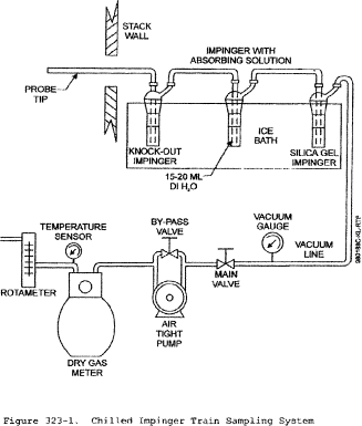 Method 325A -
Volatile Organic Compounds from Fugitive and Area Sources: Sampler
Deployment and VOC Sample Collection 1.0 Scope and Application
Method 325A -
Volatile Organic Compounds from Fugitive and Area Sources: Sampler
Deployment and VOC Sample Collection 1.0 Scope and Application
1.1 This method describes collection of volatile organic compounds (VOCs) at or inside a facility property boundary or from fugitive and area emission sources using passive (diffusive) tube samplers (PS). The concentration of airborne VOCs at or near these potential fugitive- or area-emission sources may be determined using this method in combination with Method 325B. Companion Method 325B (Sampler Preparation and Analysis) describes preparation of sampling tubes, shipment and storage of exposed sampling tubes, and analysis of sampling tubes collected using either this passive sampling procedure or alternative active (pumped) sampling methods.
1.2 This method may be used to determine the average concentration of the select VOCs using the corresponding uptake rates listed in Method 325B, Table 12.1. Additional compounds or alternative sorbents must be evaluated as described in Addendum A of Method 325B or by one of the following national/international standard methods: ISO 16017-2:2003(E), ASTM D6196-03 (Reapproved 2009), or BS EN 14662-4:2005 (all incorporated by reference - see § 63.14), or reported in the peer-reviewed open literature.
1.3 Methods 325A and 325B are valid for the measurement of benzene. Supporting literature (References 1-8) indicates that benzene can be measured by flame ionization detection or mass spectrometry over a concentration range of approximately 0.5 micrograms per cubic meter (µg/m 3) to at least 500 µg/m 3 when industry standard (3.5 inch long × 0.25 inch outside diameter (o.d.) × 5 mm inner diameter (i.d.)) inert-coated stainless steel sorbent tubes packed with Carbograph TM 1 TD, Carbopack TM B, or Carbopack TM X or equivalent are used and when samples are accumulated over a period of 14 days.
1.4 This method may be applied to screening average airborne VOC concentrations at facility property boundaries or monitoring perimeters over an extended period of time using multiple sampling periods (e.g., 26 × 14-day sampling periods). The duration of each sampling period is normally 14 days.
1.5 This method requires the collection of local meteorological data (wind speed and direction, temperature, and barometric pressure). Although local meteorology is a component of this method, non-regulatory applications of this method may use regional meteorological data. Such applications risk that the results may not identify the precise source of the emissions.
2.0 Summary of the Method 2.1 Principle of the MethodThe diffusive passive sampler collects VOC from air for a measured time period at a rate that is proportional to the concentration of vapor in the air at that location.
2.1.1 This method describes the deployment of prepared passive samplers, including determination of the number of passive samplers needed for each survey and placement of samplers along or inside the facility property boundary depending on the size and shape of the site or linear length of the boundary.
2.1.2 The rate of sampling is specific to each compound and depends on the diffusion constants of that VOC and the sampler dimensions/characteristics as determined by prior calibration in a standard atmosphere (Reference 1).
2.1.3 The gaseous VOC target compounds migrate through a constant diffusion barrier (e.g., an air gap of fixed dimensions) at the sampling end of the diffusion sampling tube and adsorb onto the sorbent.
2.1.4 Heat and a flow of inert carrier gas are then used to extract (desorb) the retained VOCs back from the sampling end of the tube and transport/transfer them to a gas chromatograph (GC) equipped with a chromatographic column to separate the VOCs and a detector to determine the quantity of target VOCs.
2.1.5 Gaseous or liquid calibration standards loaded onto the sampling ends of clean sorbent tubes must be used to calibrate the analytical equipment.
2.1.6 This method requires the use of field blanks to ensure sample integrity associated with shipment, collection, and storage of the passive samples. It also requires the use of field duplicates to validate the sampling process.
2.1.7 At the end of each sampling period, the passive samples are collected, sealed, and shipped to a laboratory for analysis of target VOCs by thermal desorption gas chromatography, as described in Method 325B.
2.2 Application of Diffusive Sampling2.2.1 This method requires deployment of passive sampling tubes on a monitoring perimeter encompassing all known emission sources at a facility and collection of local meteorological data. It may be used to determine average concentration of VOC at a facility's “fenceline” using time integrated passive sampling (Reference 2).
2.2.2 Collecting samples and meteorological data at progressively higher frequencies may be employed to resolve shorter term concentration fluctuations and wind conditions that could introduce interfering emissions from other sources.
2.2.3 This passive sampling method provides a low cost approach to screening of fugitive or area emissions compared to active sampling methods that are based on pumped sorbent tubes or time weighted average canister sampling.
2.2.3.1 Additional passive sampling tubes may be deployed at different distances from the facility property boundary or from the geometric center of the fugitive emission source.
2.2.3.2 Additional meteorological measurements may also be collected as needed to perform preliminary gradient-based assessment of the extent of the pollution plume at ground level and the effect of “background” sources contributing to airborne VOC concentrations at the location.
2.2.4 Time-resolved concentration measurements coupled with time-resolved meteorological monitoring may be used to generate data needed for source apportionment procedures and mass flux calculations.
3.0 Definitions(See also Section 3.0 of Method 325B.)
3.1 Fenceline means the property boundary of a facility or internal monitoring perimeter established in accordance with the requirements in Section 8.2 of this method.
3.2 Passive sampler (PS) means a specific type of sorbent tube (defined in this method) that has a fixed dimension air (diffusion) gap at the sampling end and is sealed at the other end.
3.3 Passive sampling refers to the activity of quantitatively collecting VOC on sorbent tubes using the process of diffusion.
3.4 PSi is the annual average for all PS concentration results from location i.
3.5 PSi3 is the set of annual average concentration results for PSi and two sorbent tubes nearest to the PS location i.
3.6 PSip is the concentration from the sorbent tube at location i for the test period or episode p.
3.7 Sampling period is the length of time each passive sampler is exposed during field monitoring. The sampling period for this method is 14 days.
3.8 Sorbent tube (Also referred to as tube, PS tube, adsorbent tube, and sampling tube) is an inert coated stainless steel tube. Standard PS tube dimensions for this method are 3.5-inch (89 mm) long × 0.25-inch (6.4 mm) o.d. with an i.d. of 5 mm, a cross-sectional area of 19.6 mm 2 and an air gap of 15 mm. The central portion of the tube is packed with solid adsorbent material contained between 2 × 100-mesh stainless steel gauzes and terminated with a diffusion cap at the sampling end of the tube. These axial passive samplers are installed under a protective hood during field deployment.
Note:Glass and glass- (or fused silica-) lined stainless steel sorbent tubes (typically 4 mm i.d.) are also available in various lengths to suit different makes of thermal desorption equipment, but these are rarely used for passive sampling because it is more difficult to adequately define the diffusive air gap in glass or glass-line tubing. Such tubes are not recommended for this method.
4.0 Sampling Interferences 4.1 General InterferencesPassive tube samplers should be sited at a distance beyond the influence of possible obstructions such as trees, walls, or buildings at the monitoring site. Complex topography and physical site obstructions, such as bodies of water, hills, buildings, and other structures that may prevent access to a planned PS location must be taken into consideration. You must document and report siting interference with the results of this method.
4.2 Background InterferenceNearby or upwind sources of target emissions outside the facility being tested can contribute to background concentrations. Moreover, because passive samplers measure continuously, changes in wind direction can cause variation in the level of background concentrations from interfering sources during the monitoring period. This is why local meteorological information, particularly wind direction and speed, is required to be collected throughout the monitoring period. Interfering sources can include neighboring industrial facilities, transportation facilities, fueling operations, combustion sources, short-term transient sources, residential sources, and nearby highways or roads. As PS data are evaluated, the location of potential interferences with respect to PS locations and local wind conditions should be considered, especially when high PS concentration values are observed.
4.3 Tube HandlingYou must protect the PS tubes from gross external contamination during field sampling. Analytical thermal desorption equipment used to analyze PS tubes must desorb organic compounds from the interior of PS tubes and exclude contamination from external sampler surfaces in the analytical/sample flow path. If the analytical equipment does not comply with this requirement, you must wear clean, white, cotton or powder-free nitrile gloves to handle sampling tubes to prevent contamination of the external sampler surfaces. Sampling tubes must be capped with two-piece, brass, 0.25 inch, long-term storage caps fitted with combined polytetrafluoroethylene ferrules (see Section 6.1 and Method 325B) to prevent ingress of airborne contaminants outside the sampling period. When not being used for field monitoring, the capped tubes must be stored in a clean, air-tight, shipping container to prevent the collection of VOCs (see Section 6.4.2 of Method 325B).
4.4 Local Weather Conditions and Airborne ParticulatesAlthough air speeds are a constraint for many forms of passive samplers, axial tube PS devices have such a slow inherent uptake rate that they are largely immune to these effects (References 4,5). Passive samplers must nevertheless be deployed under non-emitting weatherproof hoods to moderate the effect of local weather conditions such as solar heating and rain. The cover must not impede the ingress of ambient air. Sampling tubes should also be orientated vertically and pointing downwards, to minimize accumulation of particulates.
4.5 TemperatureThe normal working range for field sampling for sorbent packing is 0-40 °C (References 6,7). Note that most published passive uptake rate data for sorbent tubes is quoted at 20 °C. Note also that, as a rough guide, an increase in temperature of 10 °C will reduce the collection capacity for a given analyte on a given sorbent packing by a factor of 2, but the uptake rate will not change significantly (Reference 4).
5.0 SafetyThis method does not purport to include all safety issues or procedures needed when deploying or collecting passive sampling tubes. Precautions typical of field air sampling projects are required. Tripping, falling, electrical, and weather safety considerations must all be included in plans to deploy and collect passive sampling tubes.
6.0 Sampling Equipment and Supplies, and Pre-Deployment PlanningThis section describes the equipment and supplies needed to deploy passive sampling monitoring equipment at a facility property boundary. Details of the passive sampling tubes themselves and equipment required for subsequent analysis are described in Method 325B.
6.1 Passive Sampling TubesThe industry standard PS tubes used in this method must meet the specific configuration and preparation requirements described in Section 3.0 of this method and Section 6.1 of Method 325B.
Note:The use of PS tubes packed with various sorbent materials for monitoring a wide variety of organic compounds in ambient air has been documented in the literature (References 4-10). Other sorbents may be used in standard passive sampling tubes for monitoring additional target compound(s) once their uptake rate and performance has been demonstrated following procedures in Addendum A to Method 325B. Guidance on sorbent selection can also be obtained from relevant national and international standard methods such as ASTM D6196-03 (Reapproved 2009) (Reference 14) and ISO 16017-2:2003(E) (Reference 13) (both incorporated by reference - see § 63.14).
6.2 Passive or Diffusive Sampling CapOne diffusive sampling cap is required per PS tube. The cap fits onto the sampling end of the tube during air monitoring. The other end of the tube remains sealed with the long-term storage cap. Each diffusive sampling cap is fitted with a stainless steel gauze, which defines the outer limit of the diffusion air gap.
6.3 Sorbent Tube Protection CoverA simple weatherproof hood, suitable for protecting passive sampling tubes from the worst of the weather (see Section 4.4) consists of an inverted cone/funnel constructed of an inert, non-outgassing material that fits over the diffusive tube, with the open (sampling) end of the tube projecting just below the cone opening. An example is shown in Figure 6.1 (Adapted from Reference 13).
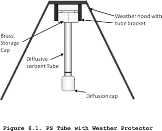 6.4
Thermal Desorption Apparatus
6.4
Thermal Desorption Apparatus
If the analytical thermal desorber that will subsequently be used to analyze the passive sampling tubes does not meet the requirement to exclude outer surface contaminants from the sample flow path (see Section 6.6 of Method 325B), then clean, white, cotton or powder-free nitrile gloves must be used for handling the passive sampling tubes during field deployment.
6.5 Sorbent SelectionSorbent tube configurations, sorbents or other VOC not listed in this method must be evaluated according to Method 325B, Addendum A or ISO 16017-2:2003(E) (Reference 13) (incorporated by reference - see § 63.14). The supporting evaluation and verification data described in Method 325B, Addendum A for configurations or compounds different from the ones described in this method must meet the performance requirements of Method 325A/B and must be submitted with the test plan for your measurement program.
7.0 Reagents and StandardsNo reagents or standards are needed for the field deployment and collection of passive sampling tubes. Specifications for sorbents, gas and liquid phase standards, preloaded standard tubes, and carrier gases are covered in Section 7 of Method 325B.
8.0 Sample Deployment, Recovery, and StoragePre-deployment and planning steps are required before field deployment of passive sampling tubes. These activities include but are not limited to conducting a site visit, determining suitable and required monitoring locations, and determining the monitoring frequency to be used.
8.1 Conducting the Site Visit8.1.1 Determine the size and shape of the facility footprint in order to determine the required number of monitoring locations.
8.1.2 Identify obstacles or obstructions (buildings, roads, fences), hills and other terrain issues (e.g., bodies of water or swamp land) that could interfere with air parcel flow to the sampler or that prevent reasonable access to the location. You may use the general guidance in Section 4.1 of this method during the site visit to identify sampling locations. You must evaluate the placement of each passive sampler to determine if the conditions in this section are met.
8.1.3 Identify to the extent possible and record potential off-site source interferences (e.g., neighboring industrial facilities, transportation facilities, fueling operations, combustion sources, short-term transient sources, residential sources, nearby highways).
8.1.4 Identify the closest available meteorological station. Identify potential locations for one or more on-site or near-site meteorological station(s) following the guidance in EPA-454/B-08-002 (Reference 11) (incorporated by reference - see § 63.14).
8.2 Determining Sampling Locations (References 2, 3)8.2.1 The number and placement of the passive samplers depends on the size, the shape of the facility footprint or the linear distance around the facility, and the proximity of emission sources near the property boundaries. Aerial photographs or site maps may be used to determine the size (acreage) and shape of the facility or the length of the monitoring perimeter. Place passive samplers on an internal monitoring perimeter on or inside the facility boundary encompassing all emission sources at the facility at different angles circling the geometric center of the facility or at different distances based on the monitoring perimeter length of the facility.
Note:In some instances, permanent air monitoring stations may already be located in close proximity to the facility. These stations may be operated and maintained by the site, or local or state regulatory agencies. If access to the station is possible, a PS may be deployed adjacent to other air monitoring instrumentation. A comparison of the pollutant concentrations measured with the PS to concentrations measured by site instrumentation may be used as an optional data quality indicator to assess the accuracy of PS results.
8.2.1.1 The monitoring perimeter may be located between the property boundary and any potential emission source near the property boundary, as long as the distance from the source to the monitoring perimeter is at least 50 meters (162 feet). If a potential emissions source is within 50 meters (162 feet) of the property boundary, the property boundary shall be used as the monitoring perimeter near that source.
8.2.1.2 Samplers need only be placed around the monitoring perimeter and not along internal roads or other right of ways that may bisect the facility.
8.2.1.3 An extra sampler must be placed near known sources of VOCs if potential emission sources are within 50 meters (162 feet) of the boundary and the source or sources are located between two monitors. Measure the distance (x) between the two monitors and place another monitor approximately halfway between (x/2 ±10 percent) the two monitors. Only one extra sampler is required between two monitors to account for known sources of VOCs. For example, in Figure 8.1, the facility added three additional monitors (i.e., light shaded sampler locations), and in Figure 8.2, the facility added two additional monitors to provide sufficient coverage of all area sources.
Figure 8.1. Facility with a Regular Shape Between 750 and 1,500 Acres in Area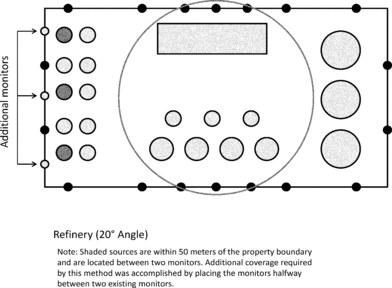
 Figure 8.1.
Facility with a Regular Shape Between 750 and 1,500 Acres in Area
Figure 8.1.
Facility with a Regular Shape Between 750 and 1,500 Acres in Area
8.2.2 Option 1 for Determining Sampling Locations.
8.2.2.1 For facilities with a regular (circular, triangular, rectangular, or square) shape, determine the geographic center of the facility.
8.2.2.1.1 For facilities with an area of less than or equal to 750 acres, measure angles of 30 degrees from the center point for a total of twelve 30 degree measurements evenly spaced (±1 degree).
8.2.2.1.2 For facilities covering an area greater than 750 acres but less than or equal to 1,500 acres, measure angles of 20 degrees from the center point for a total of eighteen 20 degree measurements evenly spaced (±1 degree). Figure 8.1 shows the monitor placement around the property boundary of a facility with an area between 750 and 1,500 acres. Monitor placements are represented with black dots along the property boundary.
8.2.2.1.3 For facilities covering an area greater than 1,500 acres, measure angles of 15 degrees from the center point for a total of twenty-four 15 degree measurements evenly spaced (±1 degree).
8.2.2.1.4 Locate each sampling point where the measured angle intersects the outer monitoring perimeter.
8.2.2.2 For irregularly shaped facilities, divide the area into a set of connecting subarea circles, triangles or rectangles to determine sampling locations. The subareas must be defined such that a circle can reasonably encompass the subarea. Then determine the geometric center point of each of the subareas.
8.2.2.2.1 If a subarea is less than or equal to 750 acres (e.g., Figure 8.3), measure angles of 30 degrees from the center point for a total of twelve 30 degree measurements (±1 degree).
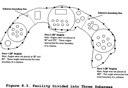
8.2.2.2.2 If a subarea is greater than 750 acres but less than or equal to 1,500 acres (e.g., Figure 8.4), measure angles of 20 degrees from the center point for a total of eighteen 20 degree measurements (±1 degree).
8.2.2.2.3 If a subarea is greater than 1,500 acres, measure angles of 15 degrees from the center for a total of twenty-four 15 degree measurements (±1 degree).
8.2.2.2.4 Locate each sampling point where the measured angle intersects the outer monitoring perimeter. Sampling points need not be placed closer than 152 meters (500 feet) apart (or 76 meters (250 feet) if known sources are within 50 meters (162 feet) of the monitoring perimeter), as long as a minimum of 3 monitoring locations are used for each subarea.
8.2.2.2.5 Sampling sites are not needed at the intersection of an inner boundary with an adjacent subarea. The sampling location must be sited where the measured angle intersects the subarea's outer monitoring perimeter.
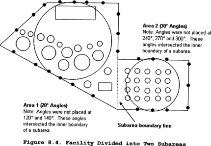
8.2.3 Option 2 for Determining Sampling Locations.
8.2.3.1 For facilities with a monitoring perimeter length of less than 7,315 meters (24,000 feet), a minimum of twelve sampling locations evenly spaced ±10 percent of the location interval is required.
8.2.3.2 For facilities with a monitoring perimeter length greater than or equal to 7,315 meters (24,000 feet), sampling locations are spaced 610 ± 76 meters (2,000 ± 250 feet) apart.
8.2.3.3 Unless otherwise specified in an applicable regulation, permit or other requirement, for small disconnected subareas with known sources within 50 meters (162 feet) of the monitoring perimeter, sampling points need not be placed closer than 152 meters (500 feet) apart as long as a minimum of 3 monitoring locations are used for each subarea.
8.3 Siting a Meteorological StationA meteorological station is required at or near the facility you are monitoring. A number of commercially available meteorological stations can be used. Information on meteorological instruments can be found in EPA-454/R-99-005 (Reference 11) (incorporated by reference - see § 63.14). Some important considerations for siting of meteorological stations are detailed below.
8.3.1 Place meteorological stations in locations that represent conditions affecting the transport and dispersion of pollutants in the area of interest. Complex terrain may require the use of more than one meteorological station.
8.3.2 Deploy wind instruments over level, open terrain at a height of 10 meters (33 feet). If possible, locate wind instruments at a distance away from nearby structures that is equal to at least 10 times the height of the structure.
8.3.3 Protect meteorological instruments from thermal radiation and adequately ventilate them using aspirated shields. The temperature sensor must be located at a distance away from any nearby structures that is equal to at least four times the height of the structure. Temperature sensors must be located at least 30 meters (98 feet) from large paved areas.
8.3.4 Collect and record meteorological data, including wind speed, wind direction, temperature and barometric pressure on an hourly basis. Calculate average unit vector wind direction, sigma theta, temperature and barometric pressure per sampling period to enable calculation of concentrations at standard conditions. Supply this information to the laboratory.
8.3.5 Identify and record the location of the meteorological station by its GPS coordinate.
8.4 Monitoring Frequency8.4.1 Sample collection may be performed for periods up to 14 days.
8.4.2 A site screening protocol that meets method requirements may be performed by collecting samples for a year where each PS accumulates VOC for a 14-day sampling period. Study results are accumulated for the sampling periods (typically 26) over the course of one calendar year. To the extent practical, sampling tubes should be changed at approximately the same time of day at each of the monitoring sites.
8.4.3 When extenuating circumstances do not permit safe deployment or retrieval of passive samplers (e.g., extreme weather, power failure), sampler placement or retrieval earlier or later than the prescribed schedule is allowed but must occur as soon as safe access to sampling sites is possible.
8.5 Passive Sampler Deployment8.5.1 Clean (conditioned) sorbent tubes must be prepared and packaged by the laboratory as described in Method 325B and must be deployed for sampling within 30 days of conditioning.
8.5.2 Allow the tubes to equilibrate with ambient temperature (approximately 30 minutes to 1 hour) at the monitoring location before removing them from their storage/shipping container for sample collection.
8.5.3 If there is any risk that the analytical equipment will not meet the requirement to exclude contamination on outer tube surfaces from the sample flow path (see Section 6.6 of Method 325B), sample handlers must wear clean, white, cotton or powder-free nitrile gloves during PS deployment and collection and throughout any other tube handling operations.
8.5.4 Inspect the sampling tubes immediately prior to deployment. Ensure that they are intact, securely capped, and in good condition. Any suspect tubes (e.g., tubes that appear to have leaked sorbent) should be removed from the sampling set.
8.5.5 Secure passive samplers so the bottom of the diffusive sampling cap is 1.5 to 3 meters (4.9 to 9.8 feet) above ground using a pole or other secure structure at each sampling location. Orient the PS vertically and with the sampling end pointing downward to avoid ingress of particulates.
Note:Duplicate sampling assemblies must be deployed in at least one monitoring location for every 10 monitoring locations during each field monitoring period.
8.5.6 Protect the PS from rain and excessive wind velocity by placing them under the type of protective hood described in Section 6.1.3 or equivalent.
8.5.7 Remove the storage cap on the sampling end of the tube and replace it with a diffusive sampling cap at the start of the sampling period. Make sure the diffusion cap is properly seated and store the removed storage caps in the empty tube shipping container.
8.5.8 Record the start time and location details for each sampler on the field sample data sheet (see example in Section 17.0.).
8.5.9 Expose the sampling tubes for the required sampling period-normally 14-days.
8.5.10 Field blank tubes (see Section 9.3 of Method 325B) are stored outside the shipping container at representative sampling locations around the site, but with both long-term storage caps kept in place throughout the monitoring exercise. Collect at least two field blanks sorbent samples per sampling period to ensure sample integrity associated with shipment, collection, and storage.
8.6 Sorbent Tube Recovery and Meteorological Data CollectionRecover deployed sampling tubes and field blanks as follows:
8.6.1 After the sampling period is complete, immediately replace the diffusion end cap on each sampled tube with a long-term storage end cap. Tighten the seal securely by hand and then tighten an additional quarter turn with an appropriate tool. Record the stop date and time and any additional relevant information on the sample data sheet.
8.6.2 Place the sampled tubes, together with the field blanks, in the storage/shipping container. Label the storage container, but do not use paints, markers, or adhesive labels to identify the tubes. TD-compatible electronic (radio frequency identification (RFID)) tube labels are available commercially and are compatible with some brands of thermal desorber. If used, these may be programmed with relevant tube and sample information, which can be read and automatically transcribed into the sequence report by the TD system.
Note:Sampled tubes must not be placed in the same shipping container as clean conditioned sampling tubes.
8.6.3 Sampled tubes may be shipped at ambient temperature to a laboratory for sample analysis.
8.6.4 Specify whether the tubes are field blanks or were used for sampling and document relevant information for each tube using a Chain of Custody form (see example in Section 17.0) that accompanies the samples from preparation of the tubes through receipt for analysis, including the following information: Unique tube identification numbers for each sampled tube; the date, time, and location code for each PS placement; the date, time, and location code for each PS recovery; the GPS reference for each sampling location; the unique identification number of the duplicate sample (if applicable); and problems or anomalies encountered.
8.6.5 If the sorbent tubes are supplied with electronic (e.g., RFID) tags, it is also possible to allocate a sample identifier to each PS tube. In this case, the recommended format for the identification number of each sampled tube is AA-BB-CC-DD-VOC, where:
AA = Sequence number of placement on route (01, 02, 03 . . .) BB = Sampling location code (01, 02, 03 . . .) CC = 14-day sample period number (01 to 26) DD = Sample code (SA = sample, DU = duplicate, FB = field blank) VOC = 3-letter code for target compound(s) (e.g., BNZ for benzene or BTX for benzene, toluene, and xylenes) Note:Sampling start and end times/dates can also be logged using RFID tube tags.
9.0 Quality Control9.1 Most quality control checks are carried out by the laboratory and associated requirements are in Section 9.0 of Method 325B, including requirements for laboratory blanks, field blanks, and duplicate samples.
9.2 Evaluate for potential outliers the laboratory results for neighboring sampling tubes collected over the same time period. A potential outlier is a result for which one or more PS tube does not agree with the trend in results shown by neighboring PS tubes - particularly when data from those locations have been more consistent during previous sampling periods. Accidental contamination by the sample handler must be documented before any result can be eliminated as an outlier. Rare but possible examples of contamination include loose or missing storage caps or contaminated storage/shipping containers. Review data from the same and neighboring monitoring locations for the subsequent sampling periods. If the anomalous result is not repeated for that monitoring location, the episode can be ascribed to transient contamination and the data in question must be flagged for potential elimination from the dataset.
9.3 Duplicates and Field Blanks9.3.1 Collect at least one co-located/duplicate sample for every 10 field samples to determine precision of the measurements.
9.3.2 Collect at least two field blanks sorbent samples per sampling period to ensure sample integrity associated with shipment, collection, and storage. You must use the entire sampling apparatus for field blanks including unopened sorbent tubes mounted in protective sampling hoods. The tube closures must not be removed. Field blanks must be placed in two different quadrants (e.g., 90° and 270°) and remain at the sampling location for the sampling period.
10.0 Calibration and StandardizationFollow the calibration and standardization procedures for meteorological measurements in EPA-454/B-08-002 March 2008 (Reference 11) (incorporated by reference - see § 63.14). Refer to Method 325B for calibration and standardization procedures for analysis of the passive sampling tubes.
11.0 Analytical ProceduresRefer to Method 325B, which provides details for the preparation and analysis of sampled passive monitoring tubes (preparation of sampling tubes, shipment and storage of exposed sampling tubes, and analysis of sampling tubes).
12.0 Data Analysis, Calculations and Documentation 12.1 Calculate Annual Average Fenceline Concentration.After a year's worth of sampling at the facility fenceline (for example, 26 14-day samples), the average (PSi) may be calculated for any specified period at each PS location using Equation 12.1.
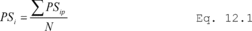 Where:
PSi = Annual average for location i. PSip = Sampling period
specific concentration from Method 325B. i = Location of passive
sampler (0 to 360°). p = The sampling period. N = The number of
sampling periods in the year (e.g., for 14-day sampling
periods, from 1 to 26). Note:
Where:
PSi = Annual average for location i. PSip = Sampling period
specific concentration from Method 325B. i = Location of passive
sampler (0 to 360°). p = The sampling period. N = The number of
sampling periods in the year (e.g., for 14-day sampling
periods, from 1 to 26). Note:
PSip is a function of sampling location-specific factors such as the contribution from facility sources, unusual localized meteorological conditions, contribution from nearby interfering sources, the background caused by integrated far-field sources and measurement error due to deployment, handling, siting, or analytical errors.
12.2 Identify Sampling Locations of InterestIf data from neighboring sampling locations are significantly different, then you may add extra sampling points to isolate background contributions or identify facility-specific “hot spots.”
12.3 Evaluate TrendsYou may evaluate trends and patterns in the PS data over multiple sampling periods to determine if elevated concentrations of target compounds are due to operations on the facility or if contributions from background sources are significant.
12.3.1 Obtain meteorological data including wind speed and wind direction or unit vector wind data from the on-site meteorological station. Use this meteorological data to determine the prevailing wind direction and speed during the periods of elevated concentrations.
12.3.2 As an option you may perform preliminary back trajectory calculations (http://ready.arl.noaa.gov/HYSPLIT.php) to aid in identifying the source of the background contribution to elevated target compound concentrations.
12.3.3 Information on published or documented events on- and off-site may also be included in the associated sampling period report to explain elevated concentrations if relevant. For example, you would describe if there was a chemical spill on site, or an accident on an adjacent road.
12.3.4 Additional monitoring for shorter periods (See section 8.4) may be necessary to allow better discrimination/resolution of contributing emission sources if the measured trends and associated meteorology do not provide a clear assessment of facility contribution to the measured fenceline concentration.
12.3.5 Additional records necessary to calculate sampling period average target compound concentration can be found in Section 12.1 of Method 325B.
13.0 Method PerformanceMethod performance requirements are described in Method 325B.
14.0 Pollution Prevention[Reserved]
15.0 Waste Management[Reserved]
16.0 References 1. Ambient air quality - Standard method for measurement of benzene concentrations - Part 4: Diffusive sampling followed by thermal desorption and gas chromatography, BS EN 14662-4:2005. 2. Thoma, E.D., Miller, C.M., Chung, K.C., Parsons, N.L. and Shine, B.C. Facility Fence Line Monitoring using Passive Samplers, J. Air & Waste Mange. Assoc. 2011, 61:834-842. 3. Quality Assurance Handbook for Air Pollution C Systems, Volume II: Ambient Air Quality Monitoring Program, EPA-454/B-13-003, May 2013. Available at http://www.epa.gov/ttnamti1/files/ambient/pm25/qa/QA-Handbook-Vol-II.pdf. 4. Brown, R.H., Charlton, J. and Saunders, K.J.: The development of an improved diffusive sampler. Am. Ind. Hyg. Assoc. J. 1981, 42(12): 865-869. 5. Brown, R. H. Environmental use of diffusive samplers: evaluation of reliable diffusive uptake rates for benzene, toluene and xylene. J. Environ. Monit. 1999, 1 (1), 115-116. 6. Ballach, J.; Greuter, B.; Schultz, E.; Jaeschke, W. Variations of uptake rates in benzene diffusive sampling as a function of ambient conditions. Sci. Total Environ. 1999, 244, 203-217. 7. Brown, R. H. Monitoring the ambient environment with diffusive samplers: theory and practical considerations. J Environ. Monit. 2000, 2 (1), 1-9. 8. Buzica, D.; Gerboles, M.; Plaisance, H. The equivalence of diffusive samplers to reference methods for monitoring O3, benzene and NO2 in ambient air. J. Environ. Monit. 2008, 10 (9), 1052-1059. 9. Woolfenden, E. Sorbent-based sampling methods for volatile and semi-volatile organic compounds in air. Part 2. Sorbent selection and other aspects of optimizing air monitoring methods. J. Chromatogr. A 2010, 1217, (16), 2685-94. 10. Pfeffer, H. U.; Breuer, L. BTX measurements with diffusive samplers in the vicinity of a cokery: Comparison between ORSA-type samplers and pumped sampling. J. Environ. Monit. 2000, 2 (5), 483-486. 11. US EPA. 2000. Meteorological Monitoring Guidance for Regulatory Modeling Applications. EPA-454/R-99-005. Office of Air Quality Planning and Standards, Research Triangle Park, NC. February 2000. Available at http://www.epa.gov/scram001/guidance/met/mmgrma.pdf. 12. Quality Assurance Handbook for Air Pollution Measurement Systems. Volume IV: Meteorological Measurements Version 2.0 Final, EPA-454/B-08-002 March 2008. Available at http://www.epa.gov/ttnamti1/files/ambient/met/ Volume%20IV_Meteorological_ Measurements.pdf. 13. ISO 16017-2:2003(E), Indoor, ambient and workplace air - Sampling and analysis of volatile organic compounds by sorbent tube/thermal desorption/capillary gas chromatography. Part 2: Diffusive sampling. 14. ASTM D6196-03 (Reapproved 2009): Standard practice for selection of sorbents, sampling, and thermal desorption analysis procedures for volatile organic compounds in air. 17.0 Tables, Diagrams, Flowcharts and Validation Data Method 325B -
Volatile Organic Compounds from Fugitive and Area Sources: Sampler
Preparation and Analysis 1.0 Scope and Application
Method 325B -
Volatile Organic Compounds from Fugitive and Area Sources: Sampler
Preparation and Analysis 1.0 Scope and Application
1.1 This method describes thermal desorption/gas chromatography (TD/GC) analysis of volatile organic compounds (VOCs) from fugitive and area emission sources collected onto sorbent tubes using passive sampling. It could also be applied to the TD/GC analysis of VOCs collected using active (pumped) sampling onto sorbent tubes. The concentration of airborne VOCs at or near potential fugitive- or area-emission sources may be determined using this method in combination with Method 325A. Companion Method 325A (Sampler Deployment and VOC Sample Collection) describes procedures for deploying the sorbent tubes and passively collecting VOCs.
1.2 The preferred GC detector for this method is a mass spectrometer (MS), but flame ionization detectors (FID) may also be used. Other conventional GC detectors such as electron capture (ECD), photoionization (PID), or flame photometric (FPD) may also be used if they are selective and sensitive to the target compound(s) and if they meet the method performance criteria provided in this method.
1.3 There are 97 VOCs listed as hazardous air pollutants in Title III of the Clean Air Act Amendments of 1990. Many of these VOC are candidate compounds for this method. Compounds with known uptake rates for Carbograph TM 1 TD, Carbopack TM B, or Carbopack TM X are listed in Table 12.1. This method provides performance criteria to demonstrate acceptable performance of the method (or modifications of the method) for monitoring one or more of the compounds listed Table 12.1. If standard passive sampling tubes are packed with other sorbents or used for other analytes than those listed in Table 12.1, then method performance and relevant uptake rates should be verified according to Addendum A to this method or by one of the following national/international standard methods: ISO 16017-2:2003(E), ASTM D6196-03 (Reapproved 2009), or BS EN 14662-4:2005 (all incorporated by reference - see § 63.14), or reported in the peer-reviewed open literature.
1.4 The analytical approach using TD/GC/MS is based on previously published EPA guidance in Compendium Method TO-17 (http://www.epa.gov/ttnamti1/airtox.html#compendium) (Reference 1), which describes active (pumped) sampling of VOCs from ambient air onto tubes packed with thermally stable adsorbents.
1.5 Inorganic gases not suitable for analysis by this method include oxides of carbon, nitrogen and sulfur, ozone (O3), and other diatomic permanent gases. Other pollutants not suitable for this analysis method include particulate pollutants, (i.e., fumes, aerosols, and dusts), compounds too labile (reactive) for conventional GC analysis, and VOCs that are more volatile than propane.
2.0 Summary of Method2.1 This method provides procedures for the preparation, conditioning, blanking, and shipping of sorbent tubes prior to sample collection.
2.2 Laboratory and field personnel must have experience of sampling trace-level VOCs using sorbent tubes (References 2,5) and must have experience operating thermal desorption/GC/multi-detector instrumentation.
2.3 Key steps of this method as implemented for each sample tube include: Stringent leak testing under stop flow, recording ambient temperature conditions, adding internal standards, purging the tube, thermally desorbing the sampling tube, refocusing on a focusing trap, desorbing and transferring/injecting the VOCs from the secondary trap into the capillary GC column for separation and analysis.
2.4 Water management steps incorporated into this method include: (a) Selection of hydrophobic sorbents in the sampling tube; (b) optional dry purging of sample tubes prior to analysis; and (c) additional selective elimination of water during primary (tube) desorption (if required) by selecting trapping sorbents and temperatures such that target compounds are quantitatively retained while water is purged to vent.
3.0 Definitions(See also Section 3.0 of Method 325A).
3.1 Blanking is the desorption and confirmatory analysis of conditioned sorbent tubes before they are sent for field sampling.
3.2 Breakthrough volume and associated relation to passive sampling. Breakthrough volumes, as applied to active sorbent tube sampling, equate to the volume of air containing a constant concentration of analyte that may be passed through a sorbent tube at a given temperature before a detectable level (5 percent) of the input analyte concentration elutes from the tube. Although breakthrough volumes are directly related to active rather than passive sampling, they provide a measure of the strength of the sorbent-sorbate interaction and therefore also relate to the efficiency of the passive sampling process. The best direct measure of passive sampling efficiency is the stability of the uptake rate. Quantitative passive sampling is compromised when the sorbent no longer acts as a perfect sink - i.e., when the concentration of a target analyte immediately above the sorbent sampling surface no longer approximates to zero. This causes a reduction in the uptake rate over time. If the uptake rate for a given analyte on a given sorbent tube remains relatively constant - i.e., if the uptake rate determined for 48 hours is similar to that determined for 7 or 14 days - the user can be confident that passive sampling is occurring at a constant rate. As a general rule of thumb, such ideal passive sampling conditions typically exist for analyte:sorbent combinations where the breakthrough volume exceeds 100 L (Reference 4).
3.3 Continuing calibration verification sample (CCV). Single level calibration samples run periodically to confirm that the analytical system continues to generate sample results within acceptable agreement to the current calibration curve.
3.4 Focusing trap is a cooled, secondary sorbent trap integrated into the analytical thermal desorber. It typically has a smaller i.d. and lower thermal mass than the original sample tube allowing it to effectively refocus desorbed analytes and then heat rapidly to ensure efficient transfer/injection into the capillary GC analytical column.
3.5 High Resolution Capillary Column Chromatography uses fused silica capillary columns with an inner diameter of 320 µm or less and with a stationary phase film thickness of 5 µm or less.
3.6 h is time in hours.
3.7 i.d. is inner diameter.
3.8 min is time in minutes.
3.9 Method Detection Limit is the lowest level of analyte that can be detected in the sample matrix with 99% confidence.
3.10 MS-SCAN is the mode of operation of a GC quadrupole mass spectrometer detector that measures all ions over a given mass range over a given period of time.
3.11 MS-SIM is the mode of operation of a GC quadrupole mass spectrometer detector that measures only a single ion or a selected number of discrete ions for each analyte.
3.12 o.d. is outer diameter.
3.13 ppbv is parts per billion by volume.
3.14 Thermal desorption is the use of heat and a flow of inert (carrier) gas to extract volatiles from a solid matrix. No solvent is required.
3.15 Total ion chromatogram is the chromatogram produced from a mass spectrometer detector collecting full spectral information.
3.16 Two-stage thermal desorption is the process of thermally desorbing analytes from a sorbent tube, reconcentrating them on a focusing trap (see Section 3.4), which is then itself rapidly heated to “inject” the concentrated compounds into the GC analyzer.
3.17 VOC is volatile organic compound.
4.0 Analytical Interferences4.1 Interference from Sorbent Artifacts. Artifacts may include target analytes as well as other VOC that co-elute chromatographically with the compounds of interest or otherwise interfere with the identification or quantitation of target analytes.
4.1.1 Sorbent decomposition artifacts are VOCs that form when sorbents degenerate, e.g., when exposed to reactive species during sampling. For example, benzaldehyde, phenol, and acetophenone artifacts are reported to be formed via oxidation of the polymeric sorbent Tenax® when sampling high concentration (100-500 ppb) ozone atmospheres (Reference 5).
4.1.2 Preparation and storage artifacts are VOCs that were not completely cleaned from the sorbent tube during conditioning or that are an inherent feature of that sorbent at a given temperature.
4.2 Humidity. Moisture captured during sampling can interfere with VOC analysis. Passive sampling using tubes packed with hydrophobic sorbents, like those described in this method, minimizes water retention. However, if water interference is found to be an issue under extreme conditions, one or more of the water management steps described in Section 2.4 can be applied.
4.3 Contamination from Sample Handling. The type of analytical thermal desorption equipment selected should exclude the possibility of outer tube surface contamination entering the sample flow path (see Section 6.6). If the available system does not meet this requirement, sampling tubes and caps must be handled only while wearing clean, white cotton or powder free nitrile gloves to prevent contamination with body oils, hand lotions, perfumes, etc.
5.0 Safety5.1 This method does not address all of the safety concerns associated with its use. It is the responsibility of the user of this standard to establish appropriate field and laboratory safety and health practices prior to use.
5.2 Laboratory analysts must exercise extreme care in working with high-pressure gas cylinders.
5.3 Due to the high temperatures involved, operators must use caution when conditioning and analyzing tubes.
6.0 Equipment and Supplies6.1 Tube Dimensions and Materials. The sampling tubes for this method are 3.5-inches (89 mm) long, 1/4 inch (6.4 mm) o.d., and 5 mm i.d. passive sampling tubes (see Figure 6.1). The tubes are made of inert-coated stainless steel with the central section (up to 60 mm) packed with sorbent, typically supported between two 100 mesh stainless steel gauze. The tubes have a cross sectional area of 19.6 square mm (5 mm i.d.). When used for passive sampling, these tubes have an internal diffusion (air) gap (DG) of 1.5 cm between the sorbent retaining gauze at the sampling end of the tube, and the gauze in the diffusion cap.
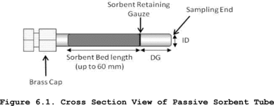 6.2 Tube
Conditioning Apparatus
6.2 Tube
Conditioning Apparatus
6.2.1 Freshly packed or newly purchased tubes must be conditioned as described in Section 9 using an appropriate dedicated tube conditioning unit or the thermal desorber. Note that the analytical TD system should be used for tube conditioning if it supports a dedicated tube conditioning mode in which effluent from contaminated tubes is directed to vent without passing through key parts of the sample flow path such as the focusing trap.
6.2.2 Dedicated tube conditioning units must be leak-tight to prevent air ingress, allow precise and reproducible temperature selection (±5 °C), offer a temperature range at least as great as that of the thermal desorber, and support inert gas flows in the range up to 100 mL/min.
Note:For safety and to avoid laboratory contamination, effluent gases from freshly packed or highly contaminated tubes should be passed through a charcoal filter during the conditioning process to prevent desorbed VOCs from polluting the laboratory atmosphere.
6.3 Tube Labeling6.3.1 Label the sample tubes with a unique permanent identification number and an indication of the sampling end of the tube. Labeling options include etching and TD-compatible electronic (radio frequency identification (RFID)) tube labels.
6.3.2 To avoid contamination, do not make ink markings of any kind on clean sorbent tubes or apply adhesive labels.
Note:TD-compatible electronic (RFID) tube labels are available commercially and are compatible with some brands of thermal desorber. If used, these may be programmed with relevant tube and sample information, which can be read and automatically transcribed into the sequence report by the TD system (see Section 8.6 of Method 325A).
6.4 Blank and Sampled Tube Storage Apparatus6.4.1 Long-term storage caps. Seal clean, blank and sampled sorbent tubes using inert, long-term tube storage caps comprising non-greased, 2-piece, 0.25-inch, metal SwageLok®-type screw caps fitted with combined polytetrafluoroethylene ferrules.
6.4.2 Storage and transportation containers. Use clean glass jars, metal cans or rigid, non-emitting polymer boxes.
Note:You may add a small packet of new activated charcoal or charcoal/silica gel to the shipping container for storage and transportation of batches of conditioned sorbent tubes prior to use. Coolers without ice packs make suitable shipping boxes for containers of tubes because the coolers help to insulate the samples from extreme temperatures (e.g., if left in a parked vehicle).
6.5 Unheated GC Injection Unit for Loading Standards Onto Blank TubesA suitable device has a simple push fit or finger-tightening connector for attaching the sampling end of blank sorbent tubes without damaging the tube. It also has a means of controlling carrier gas flow through the injector and attached sorbent tube at 50-100 mL/min and includes a low emission septum cap that allows the introduction of gas or liquid standards via appropriate syringes. Reproducible and quantitative transfer of higher boiling compounds in liquid standards is facilitated if the injection unit allows the tip of the syringe to just touch the sorbent retaining gauze inside the tube.
6.6 Thermal Desorption ApparatusThe manual or automated thermal desorption system must heat sorbent tubes while a controlled flow of inert (carrier) gas passes through the tube and out of the sampling end. The apparatus must also incorporate a focusing trap to quantitatively refocus compounds desorbed from the tube. Secondary desorption of the focusing trap should be fast/efficient enough to transfer the compounds into the high resolution capillary GC column without band broadening and without any need for further pre- or on-column focusing. Typical TD focusing traps comprise small sorbent traps (Reference 16) that are electrically-cooled using multistage Peltier cells (References 17, 18). The direction of gas flow during trap desorption should be the reverse of that used for focusing to extend the compatible analyte volatility range. Closed cycle coolers offer another cryogen-free trap cooling option. Other TD system requirements and operational stages are described in Section 11 and in Figures 17-2 through 17-4.
6.7 Thermal Desorber - GC Interface6.7.1 The interface between the thermal desorber and the GC must be heated uniformly and the connection between the transfer line insert and the capillary GC analytical column itself must be leak tight.
6.7.2 A portion of capillary column can alternatively be threaded through the heated transfer line/TD interface and connected directly to the thermal desorber.
Note:Use of a metal syringe-type needle or unheated length of fused silica pushed through the septum of a conventional GC injector is not permitted as a means of interfacing the thermal desorber to the chromatograph. Such connections result in cold spots, cause band broadening and are prone to leaks.
6.8 GC/MS Analytical Components6.8.1 The GC system must be capable of temperature programming and operation of a high resolution capillary column. Depending on the choice of column (e.g., film thickness) and the volatility of the target compounds, it may be necessary to cool the GC oven to subambient temperatures (e.g., −50 °C) at the start of the run to allow resolution of very volatile organic compounds.
6.8.2 All carrier gas lines supplying the GC must be constructed from clean stainless steel or copper tubing. Non-polytetrafluoroethylene thread sealants. Flow controllers, cylinder regulators, or other pneumatic components fitted with rubber components are not suitable.
6.9 Chromatographic ColumnsHigh-resolution, fused silica or equivalent capillary columns that provide adequate separation of sample components to permit identification and quantitation of target compounds must be used.
Note:100-percent methyl silicone or 5-percent phenyl, 95-percent methyl silicone fused silica capillary columns of 0.25- to 0.32-mm i.d. of varying lengths and with varying thicknesses of stationary phase have been used successfully for non-polar and moderately polar compounds. However, given the diversity of potential target lists, GC column choice is left to the operator, subject to the performance criteria of this method.
6.10 Mass SpectrometerLinear quadrupole, magnetic sector, ion trap or time-of-flight mass spectrometers may be used provided they meet specified performance criteria. The mass detector must be capable of collecting data from 35 to 300 atomic mass units (amu) every 1 second or less, utilizing 70 volts (nominal) electron energy in the electron ionization mode, and producing a mass spectrum that meets all the instrument performance acceptance criteria in Section 9 when 50 ηg or less of p-bromofluorobenzene is analyzed.
7.0 Reagents and Standards 7.1 Sorbent Selection7.1.1 Use commercially packed tubes meeting the requirements of this method or prepare tubes in the laboratory using sieved sorbents of particle size in the range 20 to 80 mesh that meet the retention and quality control requirements of this method.
7.1.2 This passive air monitoring method can be used without the evaluation specified in Addendum A if the type of tubes described in Section 6.1 are packed with 4-6 cm (typically 400-650 mg) of the sorbents listed in Table 12.1 and used for the respective target analytes.
Note:Although Carbopack TM X is the optimum sorbent choice for passive sampling of 1,3-butadiene, recovery of compounds with vapor pressure lower than benzene may be difficult to achieve without exceeding sorbent maximum temperature limitations (see Table 8.1). See ISO 16017-2:2003(E) or ASTM D6196-03 (Reapproved 2009) (both incorporated by reference - see § 63.14) for more details on sorbent choice for air monitoring using passive sampling tubes.
7.1.3 If standard passive sampling tubes are packed with other sorbents or used for analytes other than those tabulated in Section 12.0, method performance and relevant uptake rates should be verified according to Addendum A to this method or by following the techniques described in one of the following national/international standard methods: ISO 16017-2:2003(E), ASTM D6196-03 (Reapproved 2009), or BS EN 14662-4:2005 (all incorporated by reference - see § 63.14) - or reported in the peer-reviewed open literature. A summary table and the supporting evaluation data demonstrating the selected sorbent meets the requirements in Addendum A to this method must be submitted to the regulatory authority as part of a request to use an alternative sorbent.
7.1.4 Passive (diffusive) sampling and thermal desorption methods that have been evaluated at relatively high atmospheric concentrations (i.e., mid-ppb to ppm) and published for use in workplace air and industrial/mobile source emissions testing (References 9-20) may be applied to this procedure. However, the validity of any shorter term uptake rates must be verified and adjusted if necessary for the longer monitoring periods required by this method by following procedures described in Addendum A to this method or those presented in national/international standard methods: ISO 16017-2:2003(E), ASTM D6196-03 (Reapproved 2009), or BS EN 14662-4:2005 (all incorporated by reference-see § 63.14).
7.1.5 Suitable sorbents for passive sampling must have breakthrough volumes of at least 20 L (preferably >100 L) for the compounds of interest and must quantitatively release the analytes during desorption without exceeding maximum temperatures for the sorbent or instrumentation.
7.1.6 Repack/replace the sorbent tubes or demonstrate tube performance following the requirements in Addendum A to this method at least every 2 years or every 50 uses, whichever occurs first.
7.2 Gas Phase Standards7.2.1 Static or dynamic standard atmospheres may be used to prepare calibration tubes and/or to validate passive sampling uptake rates and can be generated from pure chemicals or by diluting concentrated gas standards. The standard atmosphere must be stable at ambient pressure and accurate to ±10 percent of the target gas concentration. It must be possible to maintain standard atmosphere concentrations at the same or lower levels than the target compound concentration objectives of the test. Test atmospheres used for validation of uptake rates must also contain at least 35 percent relative humidity.
Note:Accurate, low-(ppb-) level gas-phase VOC standards are difficult to generate from pure materials and may be unstable depending on analyte polarity and volatility. Parallel monitoring of vapor concentrations with alternative methods, such as pumped sorbent tubes or sensitive/selective on-line detectors, may be necessary to minimize uncertainty. For these reasons, standard atmospheres are rarely used for routine calibration.
7.2.2 Concentrated, pressurized gas phase standards. Accurate (±5 percent or better), concentrated gas phase standards supplied in pressurized cylinders may also be used for calibration. The concentration of the standard should be such that a 0.5-5.0 mL volume contains approximately the same mass of analytes as will be collected from a typical air sample.
7.2.3 Follow manufacturer's guidelines concerning storage conditions and recertification of the concentrated gas phase standard. Gas standards must be recertified a minimum of once every 12 months.
7.3 Liquid StandardsTarget analytes can also be introduced to the sampling end of sorbent tubes in the form of liquid calibration standards.
7.3.1 The concentration of liquid standards must be such that an injection of 0.5-2 µl of the solution introduces the same mass of target analyte that is expected to be collected during the passive air sampling period.
7.3.2 Solvent Selection. The solvent selected for the liquid standard must be pure (contaminants <10 percent of minimum analyte levels) and must not interfere chromatographically with the compounds of interest.
7.3.3 If liquid standards are sourced commercially, follow manufacturer's guidelines concerning storage conditions and shelf life of unopened and opened liquid stock standards.
Note:Commercial VOC standards are typically supplied in volatile or non-interfering solvents such as methanol.
7.3.4 Working standards must be stored at 6 °C or less and used or discarded within two weeks of preparation.
7.4 Gas Phase Internal Standards7.4.1 Gas-phase deuterated or fluorinated organic compounds may be used as internal standards for MS-based systems.
7.4.2 Typical compounds include deuterated toluene, perfluorobenzene and perfluorotoluene.
7.4.3 Use multiple internal standards to cover the volatility range of the target analytes.
7.4.4 Gas-phase standards must be obtained in pressurized cylinders and containing vendor certified gas concentrations accurate to ±5 percent. The concentration should be such that the mass of internal standard components introduced is similar to those of the target analytes collected during field monitoring.
7.5 Preloaded Standard TubesCertified, preloaded standard tubes, accurate within ±5 percent for each analyte at the microgram level and ±10 percent at the nanogram level, are available commercially and may be used for auditing and quality control purposes. (See Section 9.5 for audit accuracy evaluation criteria.) Certified preloaded tubes may also be used for routine calibration.
Note:Proficiency testing schemes are also available for TD/GC/MS analysis of sorbent tubes preloaded with common analytes such as benzene, toluene, and xylene.
7.6 Carrier GasesUse inert, 99.999-percent or higher purity helium as carrier gas. Oxygen and organic filters must be installed in the carrier gas lines supplying the analytical system according to the manufacturer's instructions. Keep records of filter and oxygen scrubber replacement.
8.0 Sorbent Tube Handling (Before and After Sampling) 8.1 Sample Tube Conditioning8.1.1 Sampling tubes must be conditioned using the apparatus described in Section 6.2.
8.1.2 New tubes should be conditioned for 2 hours to supplement the vendor's conditioning procedure. Recommended temperatures for tube conditioning are given in Table 8.1.
8.1.3 After conditioning, the blank must be verified on each new sorbent tube and on 10 percent of each batch of reconditioned tubes. See Section 9.0 for acceptance criteria.
Table 8.1 - Example Sorbent Tube Conditioning Parameters
| Sampling sorbent | Maximum temperature ( °C) |
Conditioning temperature ( °C) |
Carrier gas flow rate |
|---|---|---|---|
| Carbotrap® C | >400 | 350 | 100 mL/min |
| Carbopack TM C | |||
| Anasorb® GCB2 | |||
| Carbograph TM 1 TD | |||
| Carbotrap® | |||
| Carbopack TM B | |||
| Anasorb® GCB1 | |||
| Tenax® TA Carbopack TM X |
350 | 330 | 100 mL/min |
8.2.1 Conditioned tubes must be sealed using long-term storage caps (see Section 6.4) pushed fully down onto both ends of the PS sorbent tube, tightened by hand and then tighten an additional quarter turn using an appropriate tool.
8.2.2 The capped tubes must be kept in appropriate containers for storage and transportation (see Section 6.4.2). Containers of sorbent tubes may be stored and shipped at ambient temperature and must be kept in a clean environment.
8.2.3 You must keep batches of capped tubes in their shipping boxes or wrap them in uncoated aluminum foil before placing them in their storage container, especially before air freight, because the packaging helps hold caps in position if the tubes get very cold.
8.3 Calculating the Number of Tubes Required for a Monitoring Exercise8.3.1 Follow guidance given in Method 325A to determine the number of tubes required for site monitoring.
8.3.2 The following additional samples will also be required: Laboratory blanks as specified in Section 9.1.2 (one per analytical sequence minimum), field blanks as specified in Section 9.3.2 (two per sampling period minimum), CCV tubes as specified in Section 10.9.4. (at least one per analysis sequence or every 24 hours), and duplicate samples as specified in Section 9.4 (at least one duplicate sample is required for every 10 sampling locations during each monitoring period).
8.4 Sample Collection8.4.1 Allow the tubes to equilibrate with ambient temperature (approximately 30 minutes to 1 hour) at the monitoring location before removing them from their storage/shipping container for sample collection.
8.4.2 Tubes must be used for sampling within 30 days of conditioning (Reference 4).
8.4.3 During field monitoring, the long-term storage cap at the sampling end of the tube is replaced with a diffusion cap and the whole assembly is arranged vertically, with the sampling end pointing downward, under a protective hood or shield - See Section 6.1 of Method 325A for more details.
8.5 Sample Storage8.5.1 After sampling, tubes must be immediately resealed with long-term storage caps and placed back inside the type of storage container described in Section 6.4.2.
8.5.2 Exposed tubes may not be placed in the same container as clean tubes. They should not be taken back out of the container until ready for analysis and after they have had time to equilibrate with ambient temperature in the laboratory.
8.5.3 Sampled tubes must be inspected before analysis to identify problems such as loose or missing caps, damaged tubes, tubes that appear to be leaking sorbent or container contamination. Any and all such problems must be documented together with the unique identification number of the tube or tubes concerned. Affected tubes must not be analyzed but must be set aside.
8.5.4 Intact tubes must be analyzed within 30 days of the end of sample collection (within one week for limonene, carene, bis-chloromethyl ether, labile sulfur or nitrogen-containing compounds, and other reactive VOCs).
Note:Ensure ambient temperatures stay below 23 °C during transportation and storage. Refrigeration is not normally required unless the samples contain reactive compounds or cannot be analyzed within 30 days. If refrigeration is used, the atmosphere inside the refrigerator must be clean and free of organic solvents.
9.0 Quality Control 9.1 Laboratory BlankThe analytical system must be demonstrated to be contaminant free by performing a blank analysis at the beginning of each analytical sequence to demonstrate that the secondary trap and TD/GC/MS analytical equipment are free of any significant interferents.
9.1.1 Laboratory blank tubes must be prepared from tubes that are identical to those used for field sampling.
9.1.2 Analysis of at least one laboratory blank is required per analytical sequence. The laboratory blank must be stored in the laboratory under clean, controlled ambient temperature conditions.
9.1.3 Laboratory blank/artifact levels must meet the requirements of Section 9.2.2 (see also Table 17.1). If the laboratory blank does not meet requirements, stop and perform corrective actions and then re-analyze laboratory blank to ensure it meets requirements.
9.2 Tube Conditioning9.2.1 Conditioned tubes must be demonstrated to be free of contaminants and interference by running 10 percent of the blank tubes selected at random from each conditioned batch under standard sample analysis conditions (see Section 8.1).
9.2.2 Confirm that artifacts and background contamination are ≤ 0.2 ppbv or less than three times the detection limit of the procedure or less than 10 percent of the target compound(s) mass that would be collected if airborne concentrations were at the regulated limit value, whichever is larger. Only tubes that meet these criteria can be used for field monitoring, field or laboratory blanks, or for system calibration.
9.2.3 If unacceptable levels of VOCs are observed in the tube blanks, then the processes of tube conditioning and checking the blanks must be repeated.
9.3 Field Blanks9.3.1 Field blank tubes must be prepared from tubes that are identical to those used for field sampling - i.e., they should be from the same batch, have a similar history, and be conditioned at the same time.
9.3.2 Field blanks must be shipped to the monitoring site with the sampling tubes and must be stored at the sampling location throughout the monitoring exercise. The field blanks must be installed under a protective hood/cover at the sampling location, but the long-term storage caps must remain in place throughout the monitoring period (see Method 325A). The field blanks are then shipped back to the laboratory in the same container as the sampled tubes. Collect at least two field blank samples per sampling period to ensure sample integrity associated with shipment, collection, and storage.
9.3.3 Field blanks must contain no greater than one-third of the measured target analyte or compliance limit for field samples (see Table 17.1). If either field blank fails, flag all data that do not meet this criterion with a note that the associated results are estimated and likely to be biased high due to field blank background.
9.4 Duplicate SamplesDuplicate (co-located) samples collected must be analyzed and reported as part of method quality control. They are used to evaluate sampling and analysis precision. Relevant performance criteria are given in Section 9.9.
9.5 Method Performance CriteriaUnless otherwise noted, monitoring method performance specifications must be demonstrated for the target compounds using the procedures described in Addendum A to this method and the statistical approach presented in Method 301.
9.6 Method Detection LimitDetermine the method detection limit under the analytical conditions selected (see Section 11.3) using the procedure in Section 15 of Method 301. The method detection limit is defined for each system by making seven replicate measurements of a concentration of the compound of interest within a factor of five of the detection limit. Compute the standard deviation for the seven replicate concentrations, and multiply this value by three. The results should demonstrate that the method is able to detect analytes such as benzene at concentrations as low as 50 ppt or 1/3rd (preferably 1/10th) of the lowest concentration of interest, whichever is larger.
Note:Determining the detection limit may be an iterative process as described in 40 CFR part 136, Appendix B.
9.7 Analytical BiasAnalytical bias must be demonstrated to be within ±30 percent using Equation 9.1. Analytical bias must be demonstrated during initial setup of this method and as part of the CCV carried out with every sequence of 10 samples or less (see Section 9.14). Calibration standard tubes (see Section 10.0) may be used for this purpose.
 Eq. 9.1
Where: Spiked Value = A known mass of VOCs added to the tube.
Measured Value = Mass determined from analysis of the tube. 9.8
Analytical Precision
Eq. 9.1
Where: Spiked Value = A known mass of VOCs added to the tube.
Measured Value = Mass determined from analysis of the tube. 9.8
Analytical Precision
Demonstrate an analytical precision within ±20 percent using Equation 9.2. Analytical precision must be demonstrated during initial setup of this method and at least once per year. Calibration standard tubes may be used (see Section 10.0) and data from CCV may also be applied for this purpose.
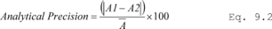 Eq. 9.2
Where: A1 = A measurement value taken from one spiked tube. A2 = A
measurement value taken from a second spiked tube. A = The average
of A1 and A2. 9.9 Field Replicate Precision
Eq. 9.2
Where: A1 = A measurement value taken from one spiked tube. A2 = A
measurement value taken from a second spiked tube. A = The average
of A1 and A2. 9.9 Field Replicate Precision
Use Equation 9.3 to determine and report replicate precision for duplicate field samples (see Section 9.4). The level of agreement between duplicate field samples is a measure of the precision achievable for the entire sampling and analysis procedure. Flag data sets for which the duplicate samples do not agree within 30 percent.
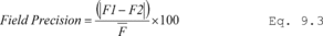 Eq. 9.3
Where: F1 = A measurement value (mass) taken from one of the two
field replicate tubes used in sampling. F2 = A measurement value
(mass) taken from the second of two field replicate tubes used in
sampling. F = The average of F1 and F2. 9.10 Desorption Efficiency
and Compound Recovery
Eq. 9.3
Where: F1 = A measurement value (mass) taken from one of the two
field replicate tubes used in sampling. F2 = A measurement value
(mass) taken from the second of two field replicate tubes used in
sampling. F = The average of F1 and F2. 9.10 Desorption Efficiency
and Compound Recovery
The efficiency of the thermal desorption method must be determined.
9.10.1 Quantitative (>95 percent) compound recovery must be demonstrated by repeat analyses on a same standard tube.
9.10.2 Compound recovery through the TD system can also be demonstrated by comparing the calibration check sample response factor obtained from direct GC injection of liquid standards with that obtained from thermal desorption analysis response factor using the same column under identical conditions.
9.10.3 If the relative response factors obtained for one or more target compounds introduced to the column via thermal desorption fail to meet the criteria in Section 9.10.1, you must adjust the TD parameters to meet the criteria and repeat the experiment. Once the thermal desorption conditions have been optimized, you must repeat this test each time the analytical system is recalibrated to demonstrate continued method performance.
9.11 Audit SamplesCertified reference standard samples must be used to audit this procedure (if available). Accuracy within 30 percent must be demonstrated for relevant ambient air concentrations (0.5 to 25 ppb).
9.12 Mass Spectrometer Tuning CriteriaTune the mass spectrometer (if used) according to manufacturer's specifications. Verify the instrument performance by analyzing a 50 ηg injection of bromofluorobenzene. Prior to the beginning of each analytical sequence or every 24 hours during continuous GC/MS operation for this method demonstrate that the bromofluorobenzene tuning performance criteria in Table 9.1 have been met.
Table 9.1 - GC/MS Tuning Criteria 1
| Target mass | Rel. to mass | Lower limit % | Upper limit % |
|---|---|---|---|
| 50 | 95 | 8 | 40 |
| 75 | 95 | 30 | 66 |
| 95 | 95 | 100 | 100 |
| 96 | 95 | 5 | 9 |
| 173 | 174 | 0 | 2 |
| 174 | 95 | 50 | 120 |
| 175 | 174 | 4 | 9 |
| 176 | 174 | 93 | 101 |
| 177 | 176 | 5 | 9 |
1 All ion abundances must be normalized to m/z 95, the nominal base peak, even though the ion abundance of m/z 174 may be up to 120 percent that of m/z 95.
Run CCV before each sequence of analyses and after every tenth sample to ensure that the previous multi-level calibration (see section 10.0) is still valid.
9.13.1 The sample concentration used for the CCV should be near the mid-point of the multi-level calibration range.
9.13.2 Quantitation software must be updated with response factors determined from the CCV standard. The percent deviation between the initial calibration and the CCV for all compounds must be within 30 percent.
9.14 CCV at the End of a SequenceRun another CCV after running each sequence of samples. The initial CCV for a subsequent set of samples may be used as the final CCV for a previous analytical sequence, provided the same analytical method is used and the subsequent set of samples is analyzed immediately (within 4 hours) after the last CCV.
9.15 Additional VerificationUse a calibration check standard from a second, separate source to verify the original calibration at least once every three months.
9.16 Integration MethodDocument the procedure used for integration of analytical data including field samples, calibration standards and blanks.
9.17 QC RecordsMaintain all QC reports/records for each TD/GC/MS analytical system used for application of this method. Routine quality control requirements for this method are listed below and summarized in Table 17.1.
10.0 Calibration and Standardization10.1 Calibrate the analytical system using standards covering the range of analyte masses expected from field samples.
10.2 Analytical results for field samples must fall within the calibrated range of the analytical system to be valid.
10.3 Calibration standard preparation must be fully traceable to primary standards of mass and/or volume, and/or be confirmed using an independent certified reference method.
10.3.1 Preparation of calibration standard tubes from standard atmospheres.
10.3.1.1 Subject to the requirements in Section 7.2.1, low-level standard atmospheres may be introduced to clean, conditioned sorbent tubes in order to produce calibration standards.
10.3.1.2 The standard atmosphere generator or system must be capable of producing sufficient flow at a constant rate to allow the required analyte mass to be introduced within a reasonable time frame and without affecting the concentration of the standard atmosphere itself.
10.3.1.3 The sampling manifold may be heated to minimize risk of condensation but the temperature of the gas delivered to the sorbent tubes may not exceed 100 °F.
10.3.1.4 The flow rates passed through the tube should be in the order of 50-100 mL/min and the volume of standard atmosphere sampled from the manifold or chamber must not exceed the breakthrough volume of the sorbent at the given temperature.
10.4 Preparation of calibration standard tubes from concentrated gas standards.
10.4.1 If a suitable concentrated gas standard (see Section 7.2.2) can be obtained, follow the manufacturer's recommendations relating to suitable storage conditions and product lifetime.
10.4.2 Introduce precise 0.5 to 500.0 mL aliquots of the standard to the sampling end of conditioned sorbent tubes in a 50-100 mL/min flow of pure carrier gas.
Note:This can be achieved by connecting the sampling end of the tube to an unheated GC injector (see Section 6.6) and introducing the aliquot of gas using a suitable gas syringe. Gas sample valves could alternatively be used to meter the standard gas volume.
10.4.3 Each sorbent tube should be left connected to the flow of gas for 2 minutes after standard introduction. As soon as each spiked tube is removed from the injection unit, seal it with long-term storage caps and place it in an appropriate tube storage/transportation container if it is not to be analyzed within 24 hours.
10.5 Preparation of calibration standard tubes from liquid standards.
10.5.1 Suitable standards are described in Section 7.3.
10.5.2 Introduce precise 0.5 to 2 µl aliquots of liquid standards to the sampling end of sorbent tubes in a flow (50-100 mL/min) of carrier gas using a precision syringe and an unheated injector (Section 6.5). The flow of gas should be sufficient to completely vaporize the liquid standard.
Note:If the analytes of interest are higher boiling than n-decane, reproducible analyte transfer to the sorbent bed is optimized by allowing the tip of the syringe to gently touch the sorbent retaining gauze at the sampling end of the tube.
10.5.3 Each sorbent tube is left connected to the flow of gas for 5 minutes after liquid standard introduction.
10.5.3.1 As soon as each spiked tube is removed from the injection unit, seal it with long-term storage caps and place it in an appropriate tube storage container if it is not to be analyzed within 24 hours.
Note:In cases where it is possible to selectively purge the solvent from the tube while all target analytes are quantitatively retained, a larger 2 µL injection may be made for optimum accuracy. However, if the solvent cannot be selectively purged and will be present during analysis, the injection volume should be as small as possible (e.g., 0.5 µL) to minimize solvent interference.
Note:This standard preparation technique requires the entire liquid plug including the tip volume be brought into the syringe barrel. The volume in the barrel is recorded, the syringe is inserted into the septum of the spiking apparatus. The liquid is then quickly injected. Any remaining liquid in the syringe tip is brought back into the syringe barrel. The volume in the barrel is recorded and the amount spiked onto the tube is the difference between the before spiking volume and the after spiking volume. A bias occurs with this method when sample is drawn continuously up into the syringe to the specified volume and the calibration solution in the syringe tip is ignored.
10.6 Preparation of calibration standard tubes from multiple standards.
10.6.1 If it is not possible to prepare one standard containing all the compounds of interest (e.g., because of chemical reactivity or the breadth of the volatility range), standard tubes can be prepared from multiple gas or liquid standards.
10.6.2 Follow the procedures described in Sections 10.4 and 10.5, respectively, for introducing each gas and/or liquid standard to the tube and load those containing the highest boiling compounds of interest first and the lightest species last.
10.7 Additional requirements for preparation of calibration tubes.
10.7.1 Storage of Calibration Standard Tubes
10.7.1.1 Seal tubes with long-term storage caps immediately after they have been disconnected from the standard loading manifold or injection apparatus.
10.7.1.2 Calibration standard tubes may be stored for no longer than 30 days and should be refrigerated if there is any risk of chemical interaction or degradation. Audit standards (see section 9.11) are exempt from this criteria and may be stored for the shelf-life specified on their certificates.
10.8 Keep records for calibration standard tubes to include the following:
10.8.1 The stock number of any commercial liquid or gas standards used.
10.8.2 A chromatogram of the most recent blank for each tube used as a calibration standard together with the associated analytical conditions and date of cleaning.
10.8.3 Date of standard loading.
10.8.4 List of standard components, approximate masses and associated confidence levels.
10.8.5 Example analysis of an identical standard with associated analytical conditions.
10.8.6 A brief description of the method used for standard preparation.
10.8.7 The standard's expiration date.
10.9 TD/GC/MS using standard tubes to calibrate system response.
10.9.1 Verify that the TD/GC/MS analytical system meets the instrument performance criteria given in Section 9.1.
10.9.2 The prepared calibration standard tubes must be analyzed using the analytical conditions applied to field samples (see Section 11.0) and must be selected to ensure quantitative transfer and adequate chromatographic resolution of target compounds, surrogates, and internal standards in order to enable reliable identification and quantitation of compounds of interest. The analytical conditions should also be sufficiently stringent to prevent buildup of higher boiling, non-target contaminants that may be collected on the tubes during field monitoring.
10.9.3 Calibration range. Each TD/GC/MS system must be calibrated at five concentrations that span the monitoring range of interest before being used for sample analysis. This initial multi-level calibration determines instrument sensitivity under the analytical conditions selected and the linearity of GC/MS response for the target compounds. One of the calibration points must be within a factor of five of the detection limit for the compounds of interest.
10.9.4 One of the calibration points from the initial calibration curve must be at the same concentration as the daily CCV standard (e.g., the mass collected when sampling air at typical concentrations).
10.9.5 Calibration frequency. Each GC/MS system must be recalibrated with a full 5-point calibration curve following corrective action (e.g., ion source cleaning or repair, column replacement) or if the instrument fails the daily calibration acceptance criteria.
10.9.5.1 CCV checks must be carried out on a regular routine basis as described in Section 9.14.
10.9.5.2 Quantitation ions for the target compounds are shown in Table 10.1. Use the primary ion unless interferences are present, in which case you should use a secondary ion.
Table 10.1 - Clean Air Act Volatile Organic Compounds for Passive Sorbent Sampling
| Compound | CAS No. | BP ( °C) |
Vapor pressure (mmHg) a |
MW b | Characteristic ion(s) | |
|---|---|---|---|---|---|---|
| Primary | Secondary | |||||
| 1,1-Dichloroethene | 75-35-4 | 32 | 500 | 96.9 | 61 | 96 |
| 3-Chloropropene | 107-05-1 | 44.5 | 340 | 76.5 | 76 | 41, 39, 78 |
| 1,1,2-Trichloro-1,2,2-trifluoroethane-1,1-Dichloroethane | 75-34-3 | 57.0 | 230 | 99 | 63 | 65, 83, 85, 98, 100 |
| 1,2-Dichloroethane | 107-06-2 | 83.5 | 61.5 | 99 | 62 | 98 |
| 1,1,1-Trichloroethane | 71-55-6 | 74.1 | 100 | 133.4 | 97 | 99, 61 |
| Benzene | 71-43-2 | 80.1 | 76.0 | 78 | 78 | |
| Carbon tetrachloride | 56-23-5 | 76.7 | 90.0 | 153.8 | 117 | 119 |
| 1,2-Dichloropropane | 78-87-5 | 97.0 | 42.0 | 113 | 63 | 112 |
| Trichloroethene | 79-01-6 | 87.0 | 20.0 | 131.4 | 95 | 97, 130, 132 |
| 1,1,2-Trichloroethane | 79-00-5 | 114 | 19.0 | 133.4 | 83 | 97, 85 |
| Toluene | 108-88-3 | 111 | 22.0 | 92 | 92 | 91 |
| Tetrachloroethene | 127-18-4 | 121 | 14.0 | 165.8 | 164 | 129, 131, 166 |
| Chlorobenzene | 108-90-7 | 132 | 8.8 | 112.6 | 112 | 77, 114 |
| Ethylbenzene | 100-41-4 | 136 | 7.0 | 106 | 91 | 106 |
| m,p-Xylene | 108-38-3, 106-42-3 | 138 | 6.5 | 106.2 | 106 | 91 |
| Styrene | 100-42-5 | 145 | 6.6 | 104 | 104 | 78 |
| o-Xylene | 95-47-6 | 144 | 5.0 | 106.2 | 106 | 91 |
| p-Dichlorobenzene | 106-46-7 | 173 | 0.60 | 147 | 146 | 111, 148 |
a Pressure in millimeters of mercury.
b Molecular weight.
11.1.1 Each sequence of analyses must be ordered as follows:
11.1.1.1 CCV.
11.1.1.2 A laboratory blank.
11.1.1.3 Field blank.
11.1.1.4 Sample(s).
11.1.1.5 Field blank.
11.1.1.6 CCV after 10 field samples.
11.1.1.7 CCV at the end of the sample batch.
11.2 Pre-desorption System Checks and Procedures11.2.1 Ensure all sample tubes and field blanks are at ambient temperature before removing them from the storage container.
11.2.2 If using an automated TD/GC/MS analyzer, remove the long-term storage caps from the tubes, replace them with appropriate analytical caps, and load them into the system in the sequence described in Section 11.1. Alternatively, if using a manual system, uncap and analyze each tube, one at a time, in the sequence described in Section 11.1.
11.2.3 The following thermal desorption system integrity checks and procedures are required before each tube is analyzed.
Note:Commercial thermal desorbers should implement these steps automatically.
11.2.3.1 Tube leak test: Each tube must be leak tested as soon as it is loaded into the carrier gas flow path before analysis to ensure data integrity.
11.2.3.2 Conduct the leak test at the GC carrier gas pressure, without heat or gas flow applied. Tubes that fail the leak test should not be analyzed, but should be resealed and stored intact. On automated systems, the instrument should continue to leak test and analyze subsequent tubes after a given tube has failed. Automated systems must also store and record which tubes in a sequence have failed the leak test. Information on failed tubes should be downloaded with the batch of sequence information from the analytical system.
11.2.3.3 Leak test the sample flow path. Leak check the sample flow path of the thermal desorber before each analysis without heat or gas flow applied to the sample tube. Stop the automatic sequence of tube desorption and GC analysis if any leak is detected in the main sample flow path. This process may be carried out as a separate step or as part of Section 11.2.3.2.
11.2.4 Optional Dry Purge11.2.4.1 Tubes may be dry purged with a flow of pure dry gas passing into the tube from the sampling end, to remove water vapor and other very volatile interferents if required.
11.2.5 Internal Standard (IS) Addition11.2.5.1 Use the internal standard addition function of the automated thermal desorber (if available) to introduce a precise aliquot of the internal standard to the sampling end of each tube after the leak test and shortly before primary (tube) desorption).
Note:This step can be combined with dry purging the tube (Section 11.2.4) if required.
11.2.5.2 If the analyzer does not have a facility for automatic IS addition, gas or liquid internal standard can be manually introduced to the sampling end of tubes in a flow of carrier gas using the types of procedure described in Sections 10.3 and 10.4, respectively.
11.2.6 Pre-purge. Each tube should be purged to vent with carrier gas flowing in the desorption direction (i.e., flowing into the tube from the non-sampling end) to remove oxygen before heat is applied. This is to prevent analyte and sorbent oxidation and to prevent deterioration of key analyzer components such as the GC column and mass spectrometer (if applicable). A series of schematics illustrating these steps is presented in Figures 17.2 and 17.3.
11.3 Analytical Procedure 11.3.1 Steps Required for Thermal Desorption11.3.1.1 Ensure that the pressure and purity of purge and carrier gases supplying the TD/GC/MS system, meet manufacturer specifications and the requirements of this method.
11.3.1.2 Ensure also that the analytical method selected meets the QC requirements of this method (Section 9) and that all the analytical parameters are at set point.
11.3.1.3 Conduct predesorption system checks (see Section 11.2).
11.3.1.4 Desorb the sorbent tube under conditions demonstrated to achieve >95 percent recovery of target compounds (see Section 9.5.2).
Note:Typical tube desorption conditions range from 280-350 °C for 5-15 minutes with a carrier gas flow of 30-100 mL/min passing through the tube from the non-sampling end such that analytes are flushed out of the tube from the sampling end. Desorbed VOCs are concentrated (refocused) on a secondary, cooled sorbent trap integrated into the analytical equipment (see Figure 17.4). The focusing trap is typically maintained at a temperature between −30 and +30 °C during focusing. Selection of hydrophobic sorbents for focusing and setting a trapping temperature of +25 to 27 °C aid analysis of humid samples because these settings allow selective elimination of any residual water from the system, prior to GC/MS analysis.
Note:The transfer of analytes from the tube to the focusing trap during primary (tube) desorption can be carried out splitless or under controlled split conditions (see Figure 17.4) depending on the masses of target compounds sampled and the requirements of the system - sensitivity, required calibration range, column overload limitations, etc. Instrument controlled sample splits must be demonstrated by showing the reproducibility using calibration standards. Field and laboratory blank samples must be analyzed at the same split as the lowest calibration standard. During secondary (trap) desorption the focusing trap is heated rapidly (typically at rates >40 °C/s) with inert (carrier) gas flowing through the trap (3-100 mL/min) in the reverse direction to that used during focusing.
11.3.1.5 The split conditions selected for optimum field sample analysis must also be demonstrated on representative standards.
Note:Typical trap desorption temperatures are in the range 250-360 °C, with a “hold” time of 1-3 minutes at the highest temperature. Trap desorption automatically triggers the start of GC analysis. The trap desorption can also be carried out under splitless conditions (i.e., with everything desorbed from the trap being transferred to the analytical column and GC detector) or, more commonly, under controlled split conditions (see Figure 17.4). The selected split ratio depends on the masses of target compounds sampled and the requirements of the system - sensitivity, required calibration range, column overload limitations, etc. If a split is selected during both primary (trap) desorption and secondary (trap) desorption, the overall split ratio is the product of the two. Such `double' split capability gives optimum flexibility for accommodating concentrated samples as well as trace-level samples on the TD/GC/MS analytical system. High resolution capillary columns and most GC/MS detectors tend to work best with approximately 20-200 ng per compound per tube to avoid saturation. The overall split ratio must be adjusted such that, when it is applied to the sample mass that is expected to be collected during field monitoring, the amount reaching the column will be attenuated to fall within this range. As a rule of thumb this means that ∼20 ng samples will require splitless or very low split analysis, ∼2 µg samples will require a split ratio in the order of ∼50:1 and 200 µg samples will require a double split method with an overall split ratio in the order of 2,000:1.
11.3.1.6 Analyzed tubes must be resealed with long-term storage caps immediately after analysis (manual systems) or after completion of a sequence (automated systems). This prevents contamination, minimizing the extent of tube reconditioning required before subsequent reuse.
11.3.2 GC/MS Analytical Procedure11.3.2.1 Heat/cool the GC oven to its starting set point.
11.3.2.2 If using a GC/MS system, it can be operated in either MS-Scan or MS-SIM mode (depending on required sensitivity levels and the type of mass spectrometer selected). As soon as trap desorption and transfer of analytes into the GC column triggers the start of the GC/MS analysis, collect mass spectral data over a range of masses from 35 to 300 amu. Collect at least 10 data points per eluting chromatographic peak in order to adequately integrate and quantify target compounds.
11.3.2.3 Use secondary ion quantitation only when there are sample matrix interferences with the primary ion. If secondary ion quantitation is performed, flag the data and document the reasons for the alternative quantitation procedure.
11.3.2.4 Data reduction is performed by the instruments post processing program that is automatically accessed after data acquisition is completed at the end of the GC run. The concentration of each target compound is calculated using the previously established response factors for the CCV analyzed in Section 11.1.1.6.
11.3.2.5 Whenever the thermal desorption - GC/MS analytical method is changed or major equipment maintenance is performed, you must conduct a new five-level calibration (see section 10.0). System calibration remains valid as long as results from subsequent CCV are within 30 percent of the most recent 5-point calibration (see section 9.13). Include relevant CCV data in the supporting information in the data report for each set of samples.
11.3.2.6 Document, flag and explain all sample results that exceed the calibration range. Report flags and provide documentation in the analytical results for the affected sample(s).
12.0 Data Analysis, Calculations, and Reporting 12.1 Recordkeeping Procedures for Sorbent Tubes12.1.1 Label sample tubes with a unique identification number as described in Section 6.3.
12.1.2 Keep records of the tube numbers and sorbent lots used for each sampling period.
12.1.3 Keep records of sorbent tube packing if tubes are manually prepared in the laboratory and not supplied commercially. These records must include the masses and/or bed lengths of sorbent(s) contained in each tube, the maximum allowable temperature for that tube and the date each tube was packed. If a tube is repacked at any stage, record the date of tube repacking and any other relevant information required in Section 12.1.
12.1.4 Keep records of the conditioning and blanking of tubes. These records must include, but are not limited to, the unique identification number and measured background resulting from the tube conditioning.
12.1.5 Record the location, dates, tube identification and times associated with each sample collection. Record this information on a Chain of Custody form that is sent to the analytical laboratory.
12.1.6 Field sampling personnel must complete and send a Chain of Custody to the analysis laboratory (see Section 8.6.4 of Method 325A for what information to include and Section 17.0 of this method for an example form). Duplicate copies of the Chain of Custody must be included with the sample report and stored with the field test data archive.
12.1.7 Field sampling personnel must also keep records of the unit vector wind direction, sigma theta, temperature and barometric pressure averages for the sampling period. See Section 8.3.4 of Method 325A.
12.1.8 Laboratory personnel must record the sample receipt date, and analysis date.
12.1.9 Laboratory personnel must maintain records of the analytical method and sample results in electronic or hardcopy in sufficient detail to reconstruct the calibration, sample, and quality control results from each sampling period.
12.2 Calculations12.2.1 Complete the calculations in this section to determine compliance with calibration quality control criteria (see also Table 17.1).
12.2.1.1 Response factor (RF). Calculate the RF using Equation 12.1:
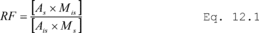 Where: As
= Peak area for the characteristic ion of the analyte. Ais = Peak
area for the characteristic ion of the internal standard. Ms = Mass
of the analyte. Mis = Mass of the internal standard.
Where: As
= Peak area for the characteristic ion of the analyte. Ais = Peak
area for the characteristic ion of the internal standard. Ms = Mass
of the analyte. Mis = Mass of the internal standard.
12.2.1.2 Standard deviation of the response factors (SDRF). Calculate the SDRF using Equation 12.2:
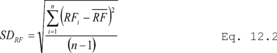 Where:
RFi = RF for each of the calibration compounds. RF = Mean RF for
each compound from the initial calibration. n = Number of
calibration standards.
Where:
RFi = RF for each of the calibration compounds. RF = Mean RF for
each compound from the initial calibration. n = Number of
calibration standards.
12.2.1.3 Percent deviation (%DEV). Calculate the %DEV using Equation 12.3:
 Where:
SDRF = Standard deviation. RF = Mean RF for each compound from the
initial calibration.
Where:
SDRF = Standard deviation. RF = Mean RF for each compound from the
initial calibration.
12.2.1.4 Relative percent difference (RPD). Calculate the RPD using Equation 12.4:
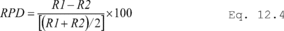 Where:
R1, R2 = Values that are being compared (i.e., response
factors in CCV).
Where:
R1, R2 = Values that are being compared (i.e., response
factors in CCV).
12.2.2 Determine the equivalent concentrations of compounds in atmospheres as follows. Correct target compound concentrations determined at the sampling site temperature and atmospheric pressure to standard conditions (25 °C and 760 mm mercury) using Equation 12.5.
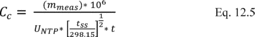 Where:
mmeas = The mass of the compound as measured in the sorbent tube
(µg). t = The exposure time (minutes). tss = The average
temperature during the collection period at the sampling site (K).
UNTP = The method defined diffusive uptake rate (sampling rate)
(mL/min).
Where:
mmeas = The mass of the compound as measured in the sorbent tube
(µg). t = The exposure time (minutes). tss = The average
temperature during the collection period at the sampling site (K).
UNTP = The method defined diffusive uptake rate (sampling rate)
(mL/min).
Note: Diffusive uptake rates (UNTP) for common VOCs, using carbon sorbents packed into sorbent tubes of the dimensions specified in section 6.1, are listed in Table 12.1. Adjust analytical conditions to keep expected sampled masses within range (see sections 11.3.1.3 to 11.3.1.5). Best possible method detection limits are typically in the order of 0.1 ppb for 1,3-butadiene and 0.05 ppb for volatile aromatics such as benzene for 14-day monitoring. However, actual detection limits will depend upon the analytical conditions selected.
Table 12.1 - Validated Sorbents and Uptake Rates (mL/min) for Selected Clean Air Act Compounds
| Compound | Carbopack TM X a |
Carbograph TM
1 TD |
Carbopack TM B |
|---|---|---|---|
| 1,1-Dichloroethene | 0.57 ±0.14 | not available | not available. |
| 3-Chloropropene | 0.51 ±0.3 | not available | not available. |
| 1,1-Dichloroethane | 0.57 ±0.1 | not available | not available. |
| 1,2-Dichloroethane | 0.57 ±0.08 | not available | not available. |
| 1,1,1-Trichloroethane | 0.51 ±0.1 | not available | not available. |
| Benzene | 0.67 ±0.06 | 0.63 ±0.07 b | 0.63 ±0.07 b. |
| Carbon tetrachloride | 0.51 ±0.06 | not available | not available. |
| 1,2-Dichloropropane | 0.52 ±0.1 | not available | not available. |
| Trichloroethene | 0.5 ±0.05 | not available | not available. |
| 1,1,2-Trichloroethane | 0.49 ±0.13 | not available | not available. |
| Toluene | 0.52 ±0.14 | 0.56 ±0.06 c | 0.56 ±0.06 c. |
| Tetrachloroethene | 0.48 ±0.05 | not available | not available. |
| Chlorobenzene | 0.51 ±0.06 | not available | not available. |
| Ethylbenzene | 0.46 ±0.07 | not available | 0.50 c. |
| m,p-Xylene | 0.46 ±0.09 | 0.47 ±0.04 c | 0.47 ±0.04 c. |
| Styrene | 0.5 ±0.14 | not available | not available. |
| o-Xylene | 0.46 ±0.12 | 0.47 ±0.04 c | 0.47 ±0.04 c. |
| p-Dichlorobenzene | 0.45 ±0.05 | not available | not available. |
a Reference 3, McClenny, J. Environ. Monit. 7:248-256. Based on 24-hour duration.
b Reference 24, BS EN 14662-4:2005 (incorporated by reference - see § 63.14). Based on 14-day duration.
c Reference 25, ISO 16017-2:2003(E) (incorporated by reference - see § 63.14). Based on 14-day duration.
The performance of this procedure for VOC not listed in Table 12.1 is determined using the procedure in Addendum A of this Method or by one of the following national/international standard methods: ISO 16017-2:2003(E), ASTM D6196-03 (Reapproved 2009), or BS EN 14662-4:2005 (all incorporated by reference - see § 63.14).
13.1 The valid range for measurement of VOC is approximately 0.5 µg/m 3 to 5 mg/m 3 in air, collected over a 14-day sampling period. The upper limit of the useful range depends on the split ratio selected (Section 11.3.1) and the dynamic range of the analytical system. The lower limit of the useful range depends on the noise from the analytical instrument detector and on the blank level of target compounds or interfering compounds on the sorbent tube (see Section 13.3).
13.2 Diffusive sorbent tubes compatible with passive sampling and thermal desorption methods have been evaluated at relatively high atmospheric concentrations (i.e., mid-ppb to ppm) and published for use in workplace air and industrial/mobile source emissions (References 15-16, 21-22).
13.3 Best possible detection limits and maximum quantifiable concentrations of air pollutants range from sub-part-per-trillion (sub-ppt) for halogenated species such as CCl4 and the freons using an electron capture detector (ECD), SIM Mode GC/MS, triple quad MS or GC/TOF MS to sub-ppb for volatile hydrocarbons collected over 72 hours followed by analysis using GC with quadrupole MS operated in the full SCAN mode.
13.3.1 Actual detection limits for atmospheric monitoring vary depending on several key factors. These factors are:
• Minimum artifact levels.
• GC detector selection.
• Time of exposure for passive sorbent tubes.
• Selected analytical conditions, particularly column resolution and split ratio.
14.0 Pollution PreventionThis method involves the use of ambient concentrations of gaseous compounds that post little or no danger of pollution to the environment.
15.0 Waste ManagementDispose of expired calibration solutions as hazardous materials. Exercise standard laboratory environmental practices to minimize the use and disposal of laboratory solvents.
16.0 References 1. Winberry, W. T. Jr., et al., Determination of Volatile Organic Compounds in Ambient Air Using Active Sampling onto Sorbent Tubes: Method TO-17r, Second Edition, U.S. Environmental Protection Agency, Research Triangle Park, NC 27711, January 1999. http://www.epa.gov/ttnamti1/airtox.html#compendium 2. Ciccioli, P., Brancaleoni, E., Cecinato, A., Sparapini, R., and Frattoni, M., “Identification and Determination of Biogenic and Anthropogenic VOCs in Forest Areas of Northern and Southern Europe and a Remote Site of the Himalaya Region by High-resolution GC-MS,” J. of Chrom., 643, pp 55-69, 1993. 3. McClenny, W.A., K.D. Oliver, H.H. Jacumin, Jr., E.H. Daughtrey, Jr., D.A. Whitaker. 2005. 24 h diffusive sampling of toxic VOCs in air onto Carbopack TM X solid adsorbent followed by thermal desorption/GC/MS analysis - laboratory studies. J. Environ. Monit. 7:248-256. 4. Markes International (www.markes.com/publications): Thermal desorption Technical Support Note 2: Prediction of uptake rates for diffusive tubes. 5. Ciccioli, P., Brancaleoni, E., Cecinato, A., DiPalo, C., Brachetti, A., and Liberti, A., “GC Evaluation of the Organic Components Present in the Atmosphere at Trace Levels with the Aid of CarbopackTM B for Preconcentration of the Sample,” J. of Chrom., 351, pp 433-449, 1986. 6. Broadway, G. M., and Trewern, T., “Design Considerations for the Optimization of a Packed Thermal Desorption Cold Trap for Capillary Gas Chromatography,” Proc. 13th Int'l Symposium on Capil. Chrom., Baltimore, MD, pp 310-320, 1991. 7. Broadway, G. M., “An Automated System for use Without Liquid Cryogen for the Determination of VOC's in Ambient Air,” Proc. 14th Int'l. Symposium on Capil. Chrom., Baltimore, MD, 1992. 8. Gibitch, J., Ogle, L., and Radenheimer, P., “Analysis of Ozone Precursor Compounds in Houston, Texas Using Automated Continuous GCs,” in Proceedings of the Air and Waste Management Association Conference: Measurement of Toxic and Related Air Pollutants, Air and Waste Management Association, Pittsburgh, PA, May 1995. 9. Vandendriessche, S., and Griepink, B., “The Certification of Benzene, Toluene and m-Xylene Sorbed on Tenax® TA in Tubes,” CRM-112 CEC, BCR, EUR12308 EN, 1989. 10. MDHS 2 (Acrylonitrile in Air), “Laboratory Method Using Porous Polymer Adsorption Tubes, and Thermal Desorption with Gas Chromatographic Analysis,” Methods for the Determination of Hazardous Substances (MDHS), UK Health and Safety Executive, Sheffield, UK. 11. MDHS 22 (Benzene in Air), “Laboratory Method Using Porous Polymer Adsorbent Tubes, Thermal Desorption and Gas Chromatography,” Method for the Determination of Hazardous Substances (MDHS), UK Health and Safety Executive, Sheffield, UK. 12. MDHS 23 (Glycol Ether and Glycol Acetate Vapors in Air), “Laboratory Method Using Tenax® Sorbent Tubes, Thermal Desorption and Gas Chromatography,” Method for the Determination of Hazardous Substances (MDHS), UK Health and Safety Executive, Sheffield, UK. 13. MDHS 40 (Toluene in air), “Laboratory Method Using Pumped Porous Polymer Adsorbent Tubes, Thermal Desorption and Gas Chromatography,” Method for the Determination of Hazardous Substances (MDHS), UK Health and Safety Executive, Sheffield, UK. 14. MDHS 60 (Mixed Hydrocarbons (C to C) in Air), “Laboratory Method Using Pumped Porous Polymer 3 10 and Carbon Sorbent Tubes, Thermal Desorption and Gas Chromatography,” Method for the Determination of Hazardous Substances (MDHS), UK Health and Safety Executive, Sheffield, UK. 15. Price, J. A., and Saunders, K. J., “Determination of Airborne Methyl tert-Butyl Ether in Gasoline Atmospheres,” Analyst, Vol. 109, pp. 829-834, July 1984. 16. Coker, D. T., van den Hoed, N., Saunders, K. J., and Tindle, P. E., “A Monitoring Method for Gasoline Vapour Giving Detailed Composition,” Ann. Occup, Hyg., Vol 33, No. 11, pp 15-26, 1989. 17. DFG, “Analytische Methoden zur prufing gesundheitsschadlicher Arbeistsstoffe,” Deutsche Forschungsgemeinschaft, Verlag Chemie, Weinheim FRG, 1985. 18. NNI, “Methods in NVN Series (Luchtkwaliteit; Werkplekatmasfeer),” Nederlands Normailsatie - Institut, Delft, The Netherlands, 1986-88. 19. “Sampling by Solid Adsorption Techniques,” Standards Association of Australia Organic Vapours, Australian Standard 2976, 1987. 20. Woolfenden, E. A., “Monitoring VOCs in Air Using Pumped Sampling onto Sorbent Tubes Followed by Thermal Desorption-capillary GC Analysis: Summary of Reported Data and Practical Guidelines for Successful Application,” J. Air & Waste Manage. Assoc., Vol. 47, 1997, pp. 20-36. 21. Validation Guidelines for Air Sampling Methods Utilizing Chromatographic Analysis, OSHA T-005, Version 3.0, May 2010, http://www.osha.gov/dts/sltc/methods/chromguide/chromguide.pdf. 22. ASTM D4597-10, Standard Practice for Sampling Workplace Atmospheres to collect Gases or Vapors with Solid Sorbent Diffusive Samplers. 23. Martin, http://www.hsl.gov.uk/media/1619/issue14.pdf. 24. BS EN 14662-4:2005, Ambient air quality - Standard method for the measurement of benzene concentrations - Part 4: Diffusive sampling followed by thermal desorption and gas chromatography. 25. ISO 16017-2:2003(E): Indoor, ambient and workplace air - Sampling and analysis of volatile organic compounds by sorbent tube/thermal desorption/capillary gas chromatography - Part 2: Diffusive sampling. 17.0 Tables, Diagrams, Flowcharts and Validation Data >Table 17.1 - Summary of GC/MS Analysis Quality Control Procedures
| Parameter | Frequency | Acceptance criteria | Corrective action |
|---|---|---|---|
| Bromofluorobenzene Instrument Tune Performance Check | Daily a prior to sample analysis | Evaluation criteria presented in Section 9.5 and Table 9.2 | (1) Retune and or (2) Perform Maintenance. |
| Five point calibration bracketing the expected sample concentration | Following any major change, repair or maintenance or if daily CCV does not meet method requirements. Recalibration not to exceed three months | (1) Percent Deviation (%DEV)
of response factors ±30% (2) Relative Retention Times (RRTs) for target peaks ±0.06 units from mean RRT |
(1) Repeat calibration sample
analysis. (2) Repeat linearity check. (3) Prepare new calibration standards as necessary and repeat analysis. |
| Calibration Verification (CCV Second source calibration verification check) | Following the calibration curve | The response factor ±30% DEV from calibration curve average response factor | (1) Repeat calibration
check. (2) Repeat calibration curve. |
| Laboratory Blank Analysis | Daily a following bromofluoro benzene and calibration check; prior to sample analysis | (1) ≤0.2 ppbv per analyte or
≤3 times the LOD, whichever is greater (2) Internal Standard (IS) area response ±40% and IS Retention Time (RT) ±0.33 min. of most recent calibration check |
(1) Repeat analysis with new
blank tube. (2) Check system for leaks, contamination. (3) Analyze additional blank. |
| Blank Sorbent Tube Certification | One tube analyzed for each batch of tubes cleaned or 10 percent of tubes whichever is greater | <0.2 ppbv per VOC targeted compound or 3 times the LOD, whichever is greater | Re-clean all tubes in batch and reanalyze. |
| Samples - Internal Standards | All samples | IS area response ±40% and IS RT ±0.33 min. of most recent calibration validation | Flag Data for possible invalidation. |
| Field Blanks | Two per sampling period | No greater than one-third of the measured target analyte or compliance limit | Flag Data for possible invalidation due to high blank bias. |
a Every 24 hours.
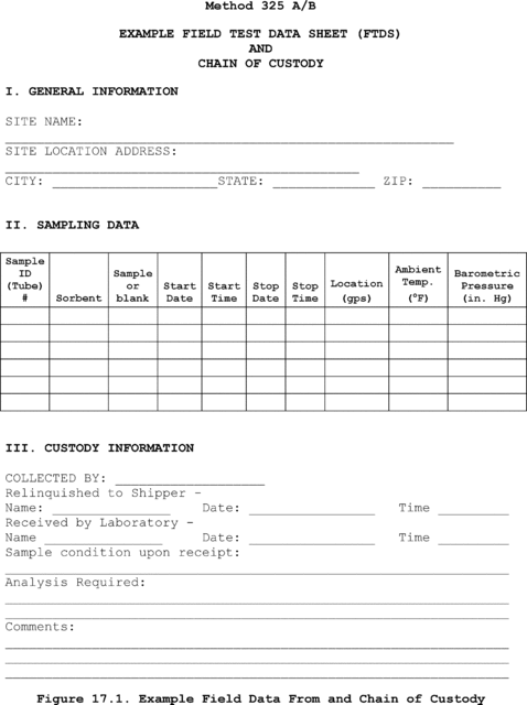
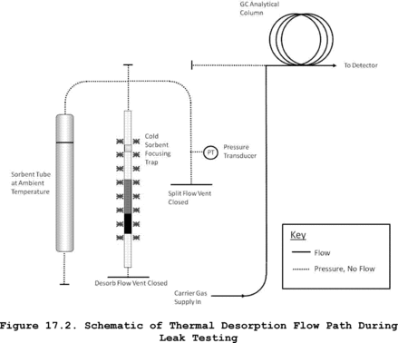
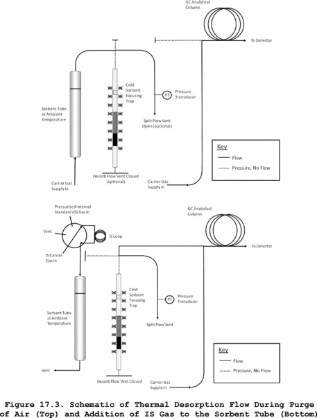
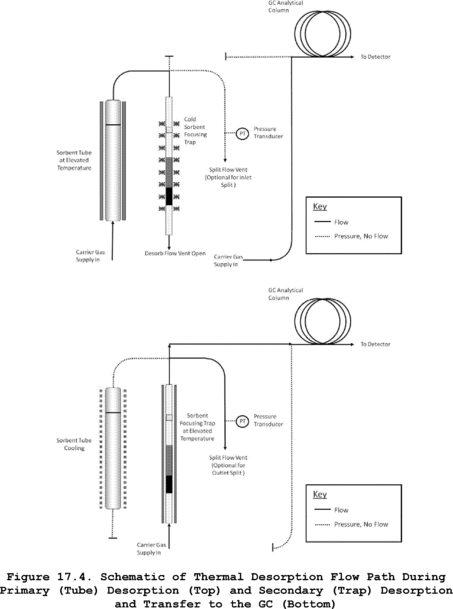
ADDENDUM A to Method 325B - Method 325 Performance Evaluation
A.1 Scope and ApplicationA.1.1 To be measured by Methods 325A and 325B, each new target volatile organic compound (VOC) or sorbent that is not listed in Table 12.1 must be evaluated by exposing the selected sorbent tube to a known concentration of the target compound(s) in an exposure chamber following the procedure in this Addendum or by following the procedures in the national/international standard methods: ISO 16017-2:2003(E), ASTM D6196-03 (Reapproved 2009), or BS EN 14662-4:2005 (all incorporated by reference - see § 63.14), or reported in peer-reviewed open literature.
A.1.2 You must determine the uptake rate and the relative standard deviation compared to the theoretical concentration of volatile material in the exposure chamber for each of the tests required in this method. If data that meet the requirement of this Addendum are available in the peer reviewed open literature for VOCs of interest collected on your passive sorbent tube configuration, then such data may be submitted in lieu of the testing required in this Addendum.
A.1.3 You must expose sorbent tubes in a test chamber to parts per trillion by volume (pptv) and low parts per billion by volume (ppbv) concentrations of VOCs in humid atmospheres to determine the sorbent tube uptake rate and to confirm compound capture and recovery.
A.2 Summary of Method Note:The technique described here is one approach for determining uptake rates for new sorbent/sorbate pairs. It is equally valid to follow the techniques described in any one of the following national/international standards methods: ISO 16017-2:2003(E), ASTM D6196-03 (Reapproved 2009), or BS EN 14662-4:2005 (all incorporated by reference - see § 63.14).
A.2.1 Known concentrations of VOC are metered into an exposure chamber containing sorbent tubes filled with media selected to capture the volatile organic compounds of interest (see Figure A.1 and A.2 for an example of the exposure chamber and sorbent tube retaining rack). VOC are diluted with humid air and the chamber is allowed to equilibrate for 6 hours. Clean passive sampling devices are placed into the chamber and exposed for a measured period of time. The passive uptake rate of the passive sampling devices is determined using the standard and dilution gas flow rates. Chamber concentrations are confirmed with whole gas sample collection and analysis or direct interface volatile organic compound measurement methods.
A.2.2 An exposure chamber and known gas concentrations must be used to challenge and evaluate the collection and recovery of target compounds from the sorbent and tube selected to perform passive measurements of VOC in atmospheres.
A.3 DefinitionsA.3.1 cc is cubic centimeter.
A.3.2 ECD is electron capture detector.
A.3.3 FID is flame ionization detector.
A.3.4 LED is light-emitting diode.
A.3.5 MFC is mass flow controller.
A.3.6 MFM is mass flow meter.
A.3.7 min is minute.
A.3.8 ppbv is parts per billion by volume.
A.3.9 ppmv is parts per million by volume.
A.3.10 PSD is passive sampling device.
A.3.11 psig is pounds per square inch gauge.
A.3.12 RH is relative humidity.
A.3.13 VOC is volatile organic compound.
A.4 InterferencesA.4.1 VOC contaminants in water can contribute interference or bias results high. Use only distilled, organic-free water for dilution gas humidification.
A.4.2 Solvents and other VOC-containing liquids can contaminate the exposure chamber. Store and use solvents and other VOC-containing liquids in the exhaust hood when exposure experiments are in progress to prevent the possibility of contamination of VOCs into the chamber through the chamber's exhaust vent.
Note:Whenever possible, passive sorbent evaluation should be performed in a VOC free laboratory.
A.4.3 PSDs should be handled by personnel wearing only clean, white cotton or powder free nitrile gloves to prevent contamination of the PSDs with oils from the hands.
A.4.4 This performance evaluation procedure is applicable to only volatile materials that can be measured accurately with direct interface gas chromatography or whole gas sample collection, concentration and analysis. Alternative methods to confirm the concentration of volatile materials in exposure chambers are subject to Administrator approval.
A.5 SafetyA.5.1 This procedure does not address all of the safety concerns associated with its use. It is the responsibility of the user of this standard to establish appropriate field and laboratory safety and health practices and determine the applicability of regulatory limitations prior to use.
A.5.2 Laboratory analysts must exercise appropriate care in working with high-pressure gas cylinders.
A.6 Equipment and SuppliesA.6.1 You must use an exposure chamber of sufficient size to simultaneously expose a minimum of eight sorbent tubes.
A.6.2 Your exposure chamber must not contain VOC that interfere with the compound under evaluation. Chambers made of glass and/or stainless steel have been used successfully for measurement of known concentration of selected VOC compounds.
A.6.3 The following equipment and supplies are needed:
• Clean, white cotton or nitrile gloves;
• Conditioned passive sampling device tubes and diffusion caps; and
• NIST traceable high resolution digital gas mass flow meters (MFMs) or flow controllers (MFCs).
A.7 Reagents and StandardsA.7.1 You must generate an exposure gas that contains between 35 and 75 percent relative humidity and a concentration of target compound(s) within 2 to 5 times the concentration to be measured in the field.
A.7.2 Target gas concentrations must be generated with certified gas standards and diluted with humid clean air. Dilution to reach the desired concentration must be done with zero grade air or better.
A.7.3 The following reagents and standards are needed:
• Distilled water for the humidification;
• VOC standards mixtures in high-pressure cylinder certified by the supplier (Note: The accuracy of the certified standards has a direct bearing on the accuracy of the measurement results. Typical vendor accuracy is ±5 percent accuracy but some VOC may only be available at lower accuracy (e.g., acrolein at 10 percent)); and
• Purified dilution air containing less than 0.2 ppbv of the target VOC.
A.8 Sample Collection, Preservation and StorageA.8.1 You must use certified gas standards diluted with humid air. Generate humidified air by adding distilled organic free water to purified or zero grade air. Humidification may be accomplished by quantitative addition of water to the air dilution gas stream in a heated chamber or by passing purified air through a humidifying bubbler. You must control the relative humidity in the test gas throughout the period of passive sampler exposure.
Note:The RH in the exposure chamber is directly proportional to the fraction of the purified air that passes through the water in the bubbler before entering the exposure chamber. Achieving uniform humidification in the proper range is a trial-and-error process with a humidifying bubbler. You may need to heat the bubbler to achieve sufficient humidity. An equilibration period of approximately 15 minutes is required following each adjustment of the air flow through the humidifier. Several adjustments or equilibration cycles may be required to achieve the desired RH level.
Note:You will need to determine both the dilution rate and the humidification rate for your design of the exposure chamber by trial and error before performing method evaluation tests.
A.8.2 Prepare and condition sorbent tubes following the procedures in Method 325B Section 7.0.
A.8.3 You must verify that the exposure chamber does not leak.
A.8.4 You must complete two evaluation tests using a minimum of eight passive sampling tubes in each test with less than 5-percent depletion of test analyte by the samplers.
A.8.4.1 Perform at least one evaluation at two to five times the estimated analytical detection limit or less.
A.8.4.2 Perform second evaluation at a concentration equivalent to the middle of the analysis calibration range.
A.8.5 You must evaluate the samplers in the test chamber operating between 35 percent and 75 percent RH, and at 25 ±5 °C. Allow the exposure chamber to equilibrate for 6 hours before starting an evaluation.
A.8.6 The flow rate through the chamber must be ≤0.5 meter per second face velocity across the sampler face.
A.8.7 Place clean, ready to use sorbent tubes into the exposure chamber for predetermined amounts of time to evaluate collection and recovery from the tubes. The exposure time depends on the concentration of volatile test material in the chamber and the detection limit required for the sorbent tube sampling application. Exposure time should match sample collection time. The sorbent tube exposure chamber time may not be less than 24 hours and should not be longer than 2 weeks.
A.8.7.1 To start the exposure, place the clean PSDs equipped with diffusion caps on the tube inlet into a retaining rack.
A.8.7.2 Place the entire retaining rack inside the exposure chamber with the diffusive sampling end of the tubes facing into the chamber flow. Seal the chamber and record the exposure start time, chamber RH, chamber temperature, PSD types and numbers, orientation of PSDs, and volatile material mixture composition (see Figure A.2).
A.8.7.3 Diluted, humidified target gas must be continuously fed into the exposure chamber during cartridge exposure. Measure the flow rate of target compound standard gas and dilution air to an accuracy of 5 percent.
A.8.7.4 Record the time, temperature, and RH at the beginning, middle, and end of the exposure time.
A.8.7.5 At the end of the exposure time, remove the PSDs from the exposure chamber. Record the exposure end time, chamber RH, and temperature.
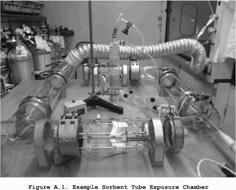
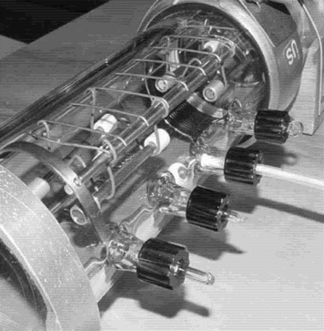
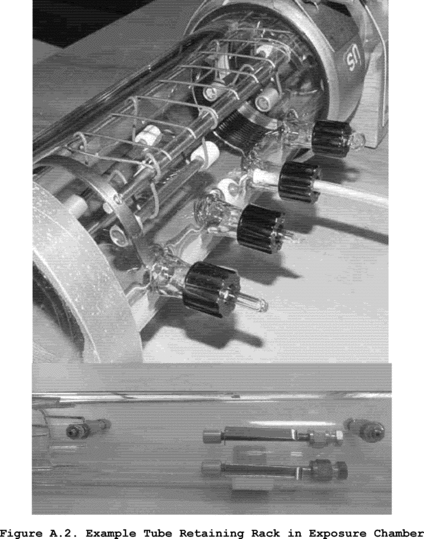 A.9 Quality
Control
A.9 Quality
Control
A.9.1 Monitor and record the exposure chamber temperature and RH during PSD exposures.
A.9.2 Measure the flow rates of standards and purified humified air immediately following PSD exposures.
A.10 Calibration and StandardizationA.10.1 Follow the procedures described in Method 325B Section 10.0 for calibration.
A.10.2 Verify chamber concentration by direct injection into a gas chromatograph calibrated for the target compound(s) or by collection of an integrated SUMMA canister followed by analysis using a preconcentration gas chromatographic method such as EPA Compendium Method TO-15, Determination of VOCs in Air Collected in Specially-Prepared Canisters and Analyzed By GC/MS.
A.10.2.1 To use direct injection gas chromatography to verify the exposure chamber concentration, follow the procedures in Method 18 of 40 CFR part 60, Appendix A-6. The method ASTM D6420-99 (Reapproved 2010) (incorporated by reference - see § 63.14) is an acceptable alternative to EPA Method 18 of 40 CFR part 60).
Note:Direct injection gas chromatography may not be sufficiently sensitive for all compounds. Therefore, the whole gas preconcentration sample and analysis method may be required to measure at low concentrations.
A.10.2.2 To verify exposure chamber concentrations using SUMMA canisters, prepare clean canister(s) and measure the concentration of VOC collected in an integrated SUMMA canister over the period used for the evaluation (minimum 24 hours). Analyze the TO-15 canister sample following EPA Compendium Method TO-15.
A.10.2.3 Compare the theoretical concentration of volatile material added to the test chamber to the measured concentration to confirm the chamber operation. Theoretical concentration must agree with the measured concentration within 30 percent.
A.11 Analysis ProcedureAnalyze the sorbent tubes following the procedures described in Section 11.0 of Method 325B.
A.12 Recordkeeping Procedures for Sorbent Tube EvaluationKeep records for the sorbent tube evaluation to include at a minimum the following information:
A.12.1 Sorbent tube description and specifications.
A.12.2 Sorbent material description and specifications.
A.12.3 Volatile analytes used in the sampler test.
A.12.4 Chamber conditions including flow rate, temperature, and relative humidity.
A.12.5 Relative standard deviation of the sampler results at the conditions tested.
A.12.6 95 percent confidence limit on the sampler overall accuracy.
A.12.7 The relative accuracy of the sorbent tube results compared to the direct chamber measurement by direct gas chromatography or SUMMA canister analysis.
A.13 Method PerformanceA.13.1 Sorbent tube performance is acceptable if the relative accuracy of the passive sorbent sampler agrees with the active measurement method by ±10 percent at the 95 percent confidence limit and the uptake ratio is equal to greater than 0.5 mL/min (1 ng/ppm-min).
Note:For example, there is a maximum deviation comparing Perkin-Elmer passive type sorbent tubes packed with Carbopack TM X of 1.3 to 10 percent compared to active sampling using the following uptake rates.
| 1,3-butadiene uptake rate mL/min |
Estimated detection limit (2 week) |
Benzene uptake rates mL/min |
Estimated detection limit (2 week) |
|
|---|---|---|---|---|
| Carbopack TM X (2 week) | 0.61 ±0.11 a | 0.1 ppbv | 0.67 a | 0.05 ppbv |
a McClenny, W.A., K.D. Oliver, H.H. Jacumin, Jr., E.H. Daughtrey, Jr., D.A. Whitaker. 2005. 24 h diffusive sampling of toxic VOCs in air onto Carbopack TM X solid adsorbent followed by thermal desorption/GC/MS analysis - laboratory studies. J. Environ. Monit. 7:248-256.
A13.2 Data Analysis and Calculations for Method Evaluation
A.13.2.1 Calculate the theoretical concentration of VOC standards using Equation A.1.
 Where: Cf
= The final concentration of standard in the exposure chamber
(ppbv). FRi = The flow rate of the target compound I (mL/min). FRt
= The flow rate of all target compounds from separate if multiple
cylinders are used (mL/min). FRa = The flow rate of dilution air
plus moisture (mL/min). Cs = The concentration of target compound
in the standard cylinder (parts per million by volume).
Where: Cf
= The final concentration of standard in the exposure chamber
(ppbv). FRi = The flow rate of the target compound I (mL/min). FRt
= The flow rate of all target compounds from separate if multiple
cylinders are used (mL/min). FRa = The flow rate of dilution air
plus moisture (mL/min). Cs = The concentration of target compound
in the standard cylinder (parts per million by volume).
A.13.2.3 Determine the uptake rate of the target gas being evaluated using Equation A.2.
 Where: MX
= The mass of analyte measured on the sampling tube (ηg). Ce = The
theoretical exposure chamber concentration (ηg/mL). Tt = The
exposure time (minutes).
Where: MX
= The mass of analyte measured on the sampling tube (ηg). Ce = The
theoretical exposure chamber concentration (ηg/mL). Tt = The
exposure time (minutes).
A.13.2.4 Estimate the variance (relative standard deviation (RSD)) of the inter-sampler results at each condition tested using Equation A.3. RSD for the sampler is estimated by pooling the variance estimates from each test run.
 Where: Xi
= The measured mass of analyte found on sorbent tube i. Xi =
The mean value of all Xi. n = The number of measurements of the
analyte.
Where: Xi
= The measured mass of analyte found on sorbent tube i. Xi =
The mean value of all Xi. n = The number of measurements of the
analyte.
A.13.2.4 Determine the percent relative standard deviation of the inter-sampler results using Equation A.4.
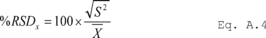
A.13.2.5 Determine the 95 percent confidence interval for the sampler results using Equation A.5. The confidence interval is determined based on the number of test runs performed to evaluate the sorbent tube and sorbent combination. For the minimum test requirement of eight samplers tested at two concentrations, the number of tests is 16 and the degrees of freedom are 15.
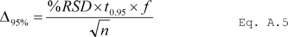 Where:
Δ95% = 95 percent confidence interval. %RSD = percent relative
standard deviation. t0.95 = The Students t statistic for f degrees
of freedom at 95 percent confidence. f = The number of degrees of
freedom. n = Number of samples.
Where:
Δ95% = 95 percent confidence interval. %RSD = percent relative
standard deviation. t0.95 = The Students t statistic for f degrees
of freedom at 95 percent confidence. f = The number of degrees of
freedom. n = Number of samples.
A.13.2.6 Determine the relative accuracy of the sorbent tube combination compared to the active sampling results using Equation A.6.
 Where: RA
= Relative accuracy. Xi = The mean value of all Xi. Xi = The
average concentration of analyte measured by the active measurement
method. Δ95% = 95 percent confidence interval. A.14 Pollution
Prevention
Where: RA
= Relative accuracy. Xi = The mean value of all Xi. Xi = The
average concentration of analyte measured by the active measurement
method. Δ95% = 95 percent confidence interval. A.14 Pollution
Prevention
This method involves the use of ambient concentrations of gaseous compounds that post little or no pollution to the environment.
A.15 Waste ManagementExpired calibration solutions should be disposed of as hazardous materials.
A.16 References1. ISO TC 146/SC 02 N 361 Workplace atmospheres - Protocol for evaluating the performance of diffusive samplers.
Method 326 - Method for Determination of Isocyanates in Stationary Source Emissions 1.0 Scope and ApplicationThis method is applicable to the collection and analysis of isocyanate compounds from the emissions associated with manufacturing processes. This method is not inclusive with respect to specifications (e.g., equipment and supplies) and sampling procedures essential to its performance. Some material is incorporated by reference from other EPA methods. Therefore, to obtain reliable results, persons using this method should have a thorough knowledge of at least Method 1, Method 2, Method 3, and Method 5 found in Appendices A-1, A-2, and A-3 in Part 60 of this title.
1.1 Analytes. This method is designed to determine the mass emission of isocyanates being emitted from manufacturing processes. The following is a table (Table 1-1) of the isocyanates and the manufacturing process at which the method has been evaluated:
Table 326-1 - Analytes
| Compound's name | CAS No. | Detection limit (ng/m 3) a | Manufacturing process |
|---|---|---|---|
| 2,4-Toluene Diisocyanate (TDI) | 584-84-9 | 106 | Flexible Foam Production. |
| 1,6-Hexamethylene Diisocyanate (HDI) | 822-06-0 | 396 | Paint Spray Booth. |
| Methylene Diphenyl Diisocyanate (MDI) | 101-68-8 | 112 | Pressed Board Production. |
| Methyl Isocyanate (MI) | 624-83-0 | 228 | Not used in production. |
a Estimated detection limits are based on a sample volume of 1 m 3 and a 10-ml sample extraction volume.
1.2 Applicability. Method 326 is a method designed for determining compliance with National Emission Standards for Hazardous Air Pollutants (NESHAP). Method 326 may also be specified by New Source Performance Standards (NSPS), State Implementation Plans (SIPs), and operating permits that require measurement of isocyanates in stationary source emissions, to determine compliance with an applicable emission standard or limit.
1.3 Data Quality Objectives (DQO). The principal objective is to ensure the accuracy of the data at the actual emissions levels and in the actual emissions matrix encountered. To meet this objective, method performance tests are required and NIST-traceable calibration standards must be used.
2.0 Summary of Method2.1 Gaseous and/or aerosol isocyanates are withdrawn from an emission source at an isokinetic sampling rate and are collected in a multicomponent sampling train. The primary components of the train include a heated probe, three impingers containing derivatizing reagent in toluene, an empty impinger, an impinger containing charcoal, and an impinger containing silica gel.
2.2 The liquid impinger contents are recovered, concentrated to dryness under vacuum, brought to volume with acetonitrile (ACN) and analyzed with a high pressure liquid chromatograph (HPLC).
3.0 Definitions [Reserved] 4.0 Interferences4.1 The greatest potential for interference comes from an impurity in the derivatizing reagent, 1-(2-pyridyl)piperazine (1,2-PP). This compound may interfere with the resolution of MI from the peak attributed to unreacted 1,2-PP.
4.2 Other interferences that could result in positive or negative bias are (1) alcohols that could compete with the 1,2-PP for reaction with an isocyanate and (2) other compounds that may co-elute with one or more of the derivatized isocyanates.
4.3 Method interferences may be caused by contaminants in solvents, reagents, glassware, and other sample processing hardware. All these materials must be routinely shown to be free from interferences under conditions of the analysis by preparing and analyzing laboratory method (or reagent) blanks.
4.3.1 Glassware must be cleaned thoroughly before using. The glassware should be washed with laboratory detergent in hot water followed by rinsing with tap water and distilled water. The glassware may be dried by baking in a glassware oven at 400 °C for at least one hour. After the glassware has cooled, it should be rinsed three times with methylene chloride and three times with acetonitrile. Volumetric glassware should not be heated to 400 °C. Instead, after washing and rinsing, volumetric glassware may be rinsed with acetonitrile followed by methylene chloride and allowed to dry in air.
4.3.2 The use of high purity reagents and solvents helps to reduce interference problems in sample analysis.
5.0 Safety5.1 Organizations performing this method are responsible for maintaining a current awareness file of Occupational Safety and Health Administration (OSHA) regulations regarding safe handling of the chemicals specified in this method. A reference file of material safety data sheets should also be made available to all personnel involved in performing the method. Additional references to laboratory safety are available.
6.0 Equipment and Supplies6.1 Sample Collection. A schematic of the sampling train used in this method is shown in Figure 207-1. This sampling train configuration is adapted from Method 5 procedures, and, as such, most of the required equipment is identical to that used in Method 5 determinations. The only new component required is a condenser.
6.1.1 Probe Nozzle. Borosilicate or quartz glass; constructed and calibrated according to Method 5, sections 6.1.1.1 and 10.1, and coupled to the probe liner using a Teflon union; a stainless steel nut is recommended for this union. When the stack temperature exceeds 210 °C (410 °F), a one-piece glass nozzle/liner assembly must be used.
6.1.2 Probe Liner. Same as Method 5, section 6.1.1.2, except metal liners shall not be used. Water-cooling of the stainless steel sheath is recommended at temperatures exceeding 500 °C (932 °F). Teflon may be used in limited applications where the minimum stack temperature exceeds 120 °C (250 °F) but never exceeds the temperature where Teflon is estimated to become unstable [approximately 210 °C (410 °F)].
6.1.3 Pitot Tube, Differential Pressure Gauge, Filter Heating System, Metering System, Barometer, Gas Density Determination Equipment. Same as Method 5, sections 6.1.1.3, 6.1.1.4, 6.1.1.6, 6.1.1.9, 6.1.2, and 6.1.3.
6.1.4 Impinger Train. Glass impingers are connected in series with leak-free ground-glass joints following immediately after the heated probe. The first impinger shall be of the Greenburg-Smith design with the standard tip. The remaining five impingers shall be of the modified Greenburg-Smith design, modified by replacing the tip with a 1.3-cm ( 1/2-in.) I.D. glass tube extending about 1.3 cm ( 1/2 in.) from the bottom of the outer cylinder. A water-jacketed condenser is placed between the outlet of the first impinger and the inlet to the second impinger to reduce the evaporation of toluene from the first impinger.
6.1.5 Moisture Measurement. For the purpose of calculating volumetric flow rate and isokinetic sampling, you must also collect either Method 4 in Appendix A-3 to this part or other moisture measurement methods approved by the Administrator concurrent with each Method 326 test run.
6.2 Sample Recovery
6.2.1 Probe and Nozzle Brushes; Polytetrafluoroethylene (PTFE) bristle brushes with stainless steel wire or PTFE handles are required. The probe brush shall have extensions constructed of stainless steel, PTFE, or inert material at least as long as the probe. The brushes shall be properly sized and shaped to brush out the probe liner and the probe nozzle.
6.2.2 Wash Bottles. Three. PTFE or glass wash bottles are recommended; polyethylene wash bottles must not be used because organic contaminants may be extracted by exposure to organic solvents used for sample recovery.
6.2.3 Glass Sample Storage Containers. Chemically resistant, borosilicate amber glass bottles, 500-mL or 1,000-mL. Bottles should be tinted to prevent the action of light on the sample. Screw-cap liners shall be either PTFE or constructed to be leak-free and resistant to chemical attack by organic recovery solvents. Narrow-mouth glass bottles have been found to leak less frequently.
6.2.4 Graduated Cylinder. To measure impinger contents to the nearest 1 ml or 1 g. Graduated cylinders shall have subdivisions not >2 mL.
6.2.5 Plastic Storage Containers. Screw-cap polypropylene or polyethylene containers to store silica gel and charcoal.
6.2.6 Funnel and Rubber Policeman. To aid in transfer of silica gel or charcoal to container (not necessary if silica gel is weighed in field).
6.2.7 Funnels. Glass, to aid in sample recovery.
6.3 Sample Preparation and Analysis.
The following items are required for sample analysis.
6.3.1 Rotary Evaporator. Buchii Model EL-130 or equivalent.
6.3.2 1000 ml Round Bottom Flask for use with a rotary evaporator.
6.3.3 Separatory Funnel. 500-ml or larger, with PTFE stopcock.
6.3.4 Glass Funnel. Short-stemmed or equivalent.
6.3.5 Vials. 15-ml capacity with PTFE lined caps.
6.3.6 Class A Volumetric Flasks. 10-ml for bringing samples to volume after concentration.
6.3.7 Filter Paper. Qualitative grade or equivalent.
6.3.8 Buchner Funnel. Porcelain with 100 mm ID or equivalent.
6.3.9 Erlenmeyer Flask. 500-ml with side arm and vacuum source.
6.3.10 HPLC with at least a binary pumping system capable of a programmed gradient.
6.3.11 Column Systems Column systems used to measure isocyanates must be capable of achieving separation of the target compounds from the nearest eluting compound or interferents with no more than 10 percent peak overlap.
6.3.12 Detector. UV detector at 254 nm. A fluorescence detector (FD) with an excitation of 240 nm and an emission at 370 nm may be also used to allow the detection of low concentrations of isocyanates in samples.
6.3.13 Data system for measuring peak areas and retention times.
7.0 Reagents and Standards7.1 Sample Collection Reagents.
7.1.1 Charcoal. Activated, 6-16 mesh. Used to absorb toluene vapors and prevent them from entering the metering device. Use once with each train and discard.
7.1.2 Silica Gel and Crushed Ice. Same as Method 5, sections 7.1.2 and 7.1.4 respectively
7.1.3 Impinger Solution. The impinger solution is prepared by mixing a known amount of 1-(2-pyridyl) piperazine (purity 99.5+%) in toluene (HPLC grade or equivalent). The actual concentration of 1,2-PP should be approximately four times the amount needed to ensure that the capacity of the derivatizing solution is not exceeded. This amount shall be calculated from the stoichiometric relationship between 1,2-PP and the isocyanate of interest and preliminary information about the concentration of the isocyanate in the stack emissions. A concentration of 130 µg/ml of 1,2-PP in toluene can be used as a reference point. This solution shall be prepared, stored in a refrigerated area away from light, and used within ten days of preparation.
7.2 Sample Recovery Reagents.
7.2.1 Toluene. HPLC grade is required for sample recovery and cleanup (see Note to 7.2.2 below).
7.2.2 Acetonitrile. HPLC grade is required for sample recovery and cleanup. Note: Organic solvents stored in metal containers may have a high residue blank and should not be used. Sometimes suppliers transfer solvents from metal to glass bottles; thus blanks shall be run before field use and only solvents with a low blank value should be used.
7.3 Analysis Reagents. Reagent grade chemicals should be used in all tests. All reagents shall conform to the specifications of the Committee on Analytical Reagents of the American Chemical Society, where such specifications are available.
7.3.1 Toluene, C6H5CH3. HPLC Grade or equivalent.
7.3.2 Acetonitrile, CH3CN (ACN). HPLC Grade or equivalent.
7.3.3 Methylene Chloride, CH2Cl2. HPLC Grade or equivalent.
7.3.4 Hexane, C6H14. HPLC Grade or equivalent.
7.3.5 Water, H2O. HPLC Grade or equivalent.
7.3.6 Ammonium Acetate, CH3CO2NH4.
7.3.7 Acetic Acid (glacial), CH3CO2H.
7.3.8 1-(2-Pyridyl)piperazine, (1,2-PP), ≥99.5% or equivalent.
7.3.9 Absorption Solution. Prepare a solution of 1-(2-pyridyl)piperazine in toluene at a concentration of 40 mg/300 ml. This solution is used for method blanks and method spikes.
7.3.10 Ammonium Acetate Buffer Solution (AAB). Prepare a solution of ammonium acetate in water at a concentration of 0.1 M by transferring 7.705 g of ammonium acetate to a 1,000 ml volumetric flask and diluting to volume with HPLC Grade water. Adjust pH to 6.2 with glacial acetic acid.
8.0 Sample Collection, Storage and Transport Note:Because of the complexity of this method, field personnel should be trained in and experienced with the test procedures in order to obtain reliable results.
8.1 Sampling
8.1.1 Preliminary Field Determinations. Same as Method 5, section 8.2.
8.1.2 Preparation of Sampling Train. Follow the general procedure given in Method 5, section 8.3.1, except for the following variations: Place 300 ml of the impinger absorbing solution in the first impinger and 200 ml each in the second and third impingers. The fourth impinger shall remain empty. The fifth and sixth impingers shall have 400 g of charcoal and 200-300 g of silica gel, respectively. Alternatively, the charcoal and silica gel may be combined in the fifth impinger. Set-up the train as in Figure 326-1. During assembly, do not use any silicone grease on ground-glass joints.
Note:During preparation and assembly of the sampling train, keep all openings where contamination can occur covered with PTFE film or aluminum foil until just before assembly or until sampling is about to begin.
8.1.3 Leak-Check Procedures. Follow the leak-check procedures given in Method 5, sections 8.4.2 (Pretest Leak-Check), 8.4.3 (Leak-Checks During the Sample Run), and 8.4.4 (Post-Test Leak-Check), with the exception that the pre-test leak-check is mandatory
8.1.4 Sampling Train Operation. Follow the general procedures given in Method 5, section 8.5. Turn on the condenser coil coolant recirculating pump and monitor the gas entry temperature. Ensure proper gas entry temperature before proceeding and again before any sampling is initiated. It is important that the gas entry temperature not exceed 50 °C (122 °F), thus reducing the loss of toluene from the first impinger. For each run, record the data required on a data sheet such as the one shown in Method 5, Figure 5-3.
8.2 Sample Recovery. Allow the probe to cool. When the probe can be handled safely, wipe off all external particulate matter near the tip of the probe nozzle and place a cap over the tip to prevent losing or gaining particulate matter. Do not cap the probe tip tightly while the sampling train is cooling down because this will create a vacuum in the train. Before moving the sample train to the cleanup site, remove the probe from the sample train and cap the opening to the probe, being careful not to lose any condensate that might be present. Cap the impingers and transfer the probe and the impinger/condenser assembly to the cleanup area. This area should be clean and protected from the weather to reduce sample contamination or loss. Inspect the train prior to and during disassembly and record any abnormal conditions. It is not necessary to measure the volume of the impingers for the purpose of moisture determination as the method is not validated for moisture determination. Treat samples as follows:
8.2.1 Container No. 1, Probe and Impinger Numbers 1 and 2. Rinse and brush the probe/nozzle first with toluene twice and then twice again with acetonitrile and place the wash into a glass container labeled with the test run identification and “Container No. 1.” When using these solvents ensure that proper ventilation is available. Quantitatively transfer the liquid from the first two impingers and the condenser into Container No. 1. Rinse the impingers and all connecting glassware twice with toluene and then twice again with acetonitrile and transfer the rinses into Container No. 1. After all components have been collected in the container, seal the container, and mark the liquid level on the bottle.
8.2.2 Container No. 2, Impingers 3 and 4. Quantitatively transfer the liquid from each impinger into a glass container labeled with the test run identification and “Container No. 2.” Rinse each impinger and all connecting glassware twice with toluene and twice again with acetonitrile and transfer the rinses into Container No. 2. After all components have been collected in the container, seal the container, and mark the liquid level on the bottle.
Note:The contents of the fifth and sixth impinger (silica gel) can be discarded.
8.2.3 Container No. 3, Reagent Blank. Save a portion of both washing solutions (toluene/acetonitrile) used for the cleanup as a blank. Transfer 200 ml of each solution directly from the wash bottle being used and combine in a glass sample container with the test identification and “Container No. 3.” Seal the container, and mark the liquid level on the bottle and add the proper label.
8.2.4 Field Train Proof Blanks. To demonstrate the cleanliness of sampling train glassware, you must prepare a full sampling train to serve as a field train proof blank just as it would be prepared for sampling. At a minimum, one complete sampling train will be assembled in the field staging area, taken to the sampling area, and leak-checked. The probe of the blank train shall be heated during and the train will be recovered as if it were an actual test sample. No gaseous sample will be passed through the sampling train. Field blanks are recovered in the same manner as described in sections 8.2.1 and 8.2.2 and must be submitted with the field samples collected at each sampling site.
8.2.5 Field Train Spike. To demonstrate the effectiveness of the sampling train, field handling, and recovery procedures you must prepare a full sampling train to serve as a field train spike just as it would be prepared for sampling. The field spike is performed in the same manner as the field train proof blank with the additional step of adding the Field Spike Solution to the first impinger after the initial leak check. The train will be recovered as if it were an actual test sample. No gaseous sample will be passed through the sampling train. Field train spikes are recovered in the same manner as described in sections 8.2.1 and 8.2.2 and must be submitted with the samples collected for each test program.
8.3 Sample Transport Procedures. Containers must remain in an upright position at all times during shipment. Samples must also be stored at <4 °C between the time of sampling and concentration. Each sample should be extracted and concentrated within 30 days after collection and analyzed within 30 days after extraction. The extracted sample must be stored at 4 °C.
8.4 Sample Custody. Proper procedures and documentation for sample chain of custody are critical to ensuring data integrity. The chain of custody procedures in ASTM D4840-99 (Reapproved 2018) e “Standard Guide for Sampling Chain-of-Custody Procedures” (incorporated by reference, see § 63.14) shall be followed for all samples (including field samples and blanks).
9.0 Quality Control9.1 Sampling. Sampling Operations. The sampling quality control procedures and acceptance criteria are listed in Table 326-2 below; see also section 9.0 of Method 5.
9.2 Analysis. The analytical quality control procedures required for this method includes the analysis of the field train proof blank, field train spike, and reagent and method blanks. Analytical quality control procedures and acceptance criteria are listed in Table 326-3 below.
9.2.1 Check for Breakthrough. Recover and determine the isocyanate(s) concentration of the last two impingers separately from the first two impingers.
9.2.2 Field Train Proof Blank. Field blanks must be submitted with the samples collected at each sampling site.
9.2.3 Reagent Blank and Field Train Spike. At least one reagent blank and a field train spike must be submitted with the samples collected for each test program.
9.2.4 Determination of Method Detection Limit. Based on your instrument's sensitivity and linearity, determine the calibration concentrations or masses that make up a representative low level calibration range. The MDL must be determined at least annually for the analytical system using an MDL study such as that found in section 15.0 to Method 301 of appendix A to part 63 of this chapter.
Table 326-2 - Sampling Quality Assurance and Quality Control
| QA/QC criteria | Acceptance criteria | Frequency | Consequence if not met |
|---|---|---|---|
| Sampling Equipment Leak Checks | ≤0.00057 m3/min (0.020 cfm) or 4% of sampling rate, whichever is less | Prior to, during (optional) and at the completion to sampling | Prior to: Repair and repeat calibration. During/Completion: None, testing should be considered invalid. |
| Dry Gas Meter Calibration - Pre-Test (individual correction factor - Yi) | within ±2% of average factor (individual) | Pre-test | Repeat calibration point. |
| Dry Gas Meter Calibration - Pre-Test (average correction factor - Yc) | 1.00 ±1% | Pre-test | Adjust the dry gas meter and recalibrate. |
| Dry Gas Meter Calibration - Post-test | Average dry gas meter calibration factor agrees with ±5% Yc | Each Test | Adjust sample volumes using the factor that gives the smallest volume. |
| Temperature sensor calibration | Absolute temperature measures by sensor within ±1.5% of a reference sensor | Prior to initial use and before each test thereafter | Recalibrate; sensor may not be used until specification is met. |
| Barometer calibration | Absolute pressure measured by instrument within ±10 mm Hg of reading with a mercury barometer or NIST traceable barometer | Prior to initial use and before each test thereafter | Recalibrate; instrument may not be used until specification is met. |
Table 326-3 - Analytical Quality Assurance and Quality Control
| QA/QC criteria | Acceptance criteria | Frequency | Consequence if not met |
|---|---|---|---|
| Calibration - Method Blanks | <5% level of expected analyte | Each analytical method blank | Locate source of contamination; reanalyze. |
| Calibration - Calibration Points | At least six calibration point bracketing the expected range of analysis | Each analytical batch | Incorporate additional calibration points to meet criteria. |
| Calibration - Linearity | Correlation coefficient >0.995 | Each analytical batch | Verify integration, reintegrate. If necessary, recalibrate. |
| Calibration - secondary standard verification | Within ±10% of true value | After each calibration | Repeat secondary standard verification, recalibrate if necessary. |
| Calibration - continual calibration verification | Within ±10% of true value | Daily and after every ten samples | Invalidate previous ten sample analysis, recalibrate and repeat calibration, reanalyze samples until successful. |
| Sample Analysis | Within the valid calibration range | Each sample | Invalidate the sample if greater than the calibration range and dilute the sample so that it is within the calibration range. Appropriately flag any value below the calibration range. |
| Replicate Samples | Within ±10% of RPD | Each sample | Evaluate integrations and repeat sample analysis as necessary. |
| Field Train Proof Blank | ≤10% level of expected analyte | Each test program | Evaluate source of contamination. |
| Field Train Spike | Within ±30% of true value | Each test program | Evaluate performance of the method and consider invalidating results. |
| Breakthrough | Final two impingers Mass collected is >5% of the total mass or >20% of the total mass when the measured results are 20% of the applicable standard. Alternatively, there is no breakthrough requirement when the measured results are 10% of the applicable standard | Each test run | Invalidate test run. |
Maintain a laboratory log of all calibrations.
10.1 Probe Nozzle, Pitot Tube Assembly, Dry Gas Metering System, Probe Heater, Temperature Sensors, Leak-Check of Metering System, and Barometer. Same as Method 5, sections 10.1, 10.2, 10.3, 10.4, 10.5, 8.4.1, and 10.6, respectively.
10.2 High Performance Liquid Chromatograph. Establish the retention times for the isocyanates of interest; retention times will depend on the chromatographic conditions. The retention times provided in Table 10-1 are provided as a guide to relative retention times when using a C18, 250 mm x 4.6 mm ID, 5µm particle size column, a 2 ml/min flow rate of a 1:9 to 6:4 Acetonitrile/Ammonium Acetate Buffer, a 50 µl sample loop, and a UV detector set at 254 nm.
Table 326-4 - Example Retention Times
| Retention times | |
|---|---|
| Compound | Retention time (minutes) |
| MI | 10.0 |
| 1,6-HDI | 19.9 |
| 2,4-TDI | 27.1 |
| MDI | 27.3 |
10.3 Preparation of Isocyanate Derivatives.
10.3.1 HDI, TDI, MDI. Dissolve 500 mg of each isocyanate in individual 100 ml aliquots of methylene chloride (MeCl2), except MDI which requires 250 ml of MeCl2. Transfer a 5-ml aliquot of 1,2-PP (see section 7.3.8) to each solution, stir and allow to stand overnight at room temperature. Transfer 150 ml aliquots of hexane to each solution to precipitate the isocyanate-urea derivative. Using a Buchner funnel, vacuum filter the solid-isocyanate-urea derivative and rinse with 50 ml of hexane. Dissolve the precipitate in a minimum aliquot of MeCl2. Repeat the hexane precipitation and filtration twice. After the third filtration, dry the crystals at 50 °C and transfer to bottles for storage. The crystals are stable for at least 21 months when stored at room temperature in a closed container.
10.3.2 MI. Prepare a 200 µg/ml stock solution of methyl isocyanate-urea, transfer 60 mg of 1,2-PP to a 100-ml volumetric flask containing 50 ml of MeCl2. Carefully transfer 20 mg of methyl isocyanate to the volumetric flask and shake for 2 minutes. Dilute the solution to volume with MeCl2 and transfer to a bottle for storage. Methyl isocyanate does not produce a solid derivative and standards must be prepared from this stock solution.
10.4 Preparation of calibration standards. Prepare a 100 µg/ml stock solution of the isocyanates of interest from the individual isocyanate-urea derivative as prepared in sections 10.3.1 and 10.3.2. This is accomplished by dissolving 1 mg of each isocyanate-urea derivative in 10 ml of Acetonitrile. Calibration standards are prepared from this stock solution by making appropriate dilutions of aliquots of the stock into Acetonitrile.
10.5 Preparation of Method Blanks. Prepare a method blank for each test program (up to twenty samples) by transferring 300 ml of the absorption solution to a 1,000-ml round bottom flask and concentrate as outlined in section 11.2.
10.6 Preparation of Field Spike Solution. Prepare a field spike solution for every test program in the same manner as calibration standards (see Section 10.4). The mass of the target isocyanate in the volume of the spike solution for the field spike train shall be equivalent to that estimated to be captured from the source concentration for each compound; alternatively, you may also prepare a solution that represents half the applicable standard.
10.7 HPLC Calibrations. See Section 11.1.
11.0 Analytical Procedure11.1 Analytical Calibration. Perform a multipoint calibration of the instrument at six or more upscale points over the desired quantitative range (multiple calibration ranges shall be calibrated, if necessary). The field samples analyzed must fall within at least one of the calibrated quantitative ranges and meet the performance criteria specified below. The lowest point in your calibration curve must be at least 5, and preferably 10, times the MDL. For each calibration curve, the value of the square of the linear correlation coefficient, i.e., r 2, must be ≥0.995, and the analyzer response must be within ±10 percent of the reference value at each upscale calibration point. Calibrations must be performed on each day of the analysis, before analyzing any of the samples. Following calibration, a secondary standard shall be analyzed. A continual calibration verification (CCV) must also be performed prior to any sample and after every ten samples. The measured value of this independently prepared standard must be within ±10 percent of the expected value. Report the results for each calibration standard secondary standard, and CCV as well as the conditions of the HPLC. The reports should include at least the peak area, height, and retention time for each isocyanate compound measured as well as a chromatogram for each standard.
11.2 Concentration of Samples. Transfer each sample to a 1,000-ml round bottom flask. Attach the flask to a rotary evaporator and gently evaporate to dryness under vacuum in a 65 °C water bath. Rinse the round bottom flask three times each with 2 ml of acetonitrile and transfer the rinse to a 10-ml volumetric flask. Dilute the sample to volume with acetonitrile and transfer to a 15-ml vial and seal with a PTFE lined lid. Store the vial ≤4 °C until analysis.
11.3 Analysis. Analyze replicative samples by HPLC, using the appropriate conditions established in section 10.2. The width of the retention time window used to make identifications should be based upon measurements of actual retention time variations of standards over the course of a day. Three times the standard deviation of a retention time for a compound can be used to calculate a suggested window size; however, the experience of the analyst should weigh heavily in the interpretation of the chromatograms. If the peak area exceeds the linear range of the calibration curve, the sample must be diluted with acetonitrile and reanalyzed. Average the replicate results for each run. For each sample you must report the same information required for analytical calibrations (Section 11.1). For non-detect or values below the detection limit of the method, you shall report the value as “<” numerical detection limit.
12.0 Data Analysis and CalculationsNomenclature and calculations, same as in Method 5, section 6, with the following additions below.
12.1 Nomenclature.
AS = Response of the sample, area counts. b = Y-intercept of the linear regression line, area counts. BR = Percent Breakthrough CA = Concentration of a specific isocyanate compound in the initial sample, µg/ml. CB = Concentration of a specific isocyanate compound in the replicate sample, µg/ml. CI = Concentration of a specific isocyanate compound in the sample, µg/ml. Crec = Concentration recovered from spike train, µg/ml. CS = Concentration of isocyanate compound in the stack gas, µg/dscm CT = Concentration of a specific isocyanate compound (Impingers 1-4), µg/dscm Cspike = Concentration spiked, µg/ml. C4 = Concentration of a specific isocyanate compound (Impingers 14), µg/dscm FIm = Mass of Free Isocyanate FTSrec = Field Train Spike Recovery Im = Mass of the Isocyanate Imw = MW of the Isocyanate IUm = Mass of Isocyanate-urea derivative IUmw = MW of the isocyanate-urea M = Slope of the linear regression line, area counts-ml/µg. mI = Mass of isocyanate in the total sample MW = Molecular weight RPD = Relative Percent Difference VF = Final volume of concentrated sample, typically 10 ml. Vmstd = Volume of gas sample measured by the dry-gas meter, corrected to standard conditions, dscm (dscf).12.2 Conversion from Isocyanate to the Isocyanate-urea derivative. The equation for converting the amount of free isocyanate to the corresponding amount of isocyanate-urea derivative is as follows:
12.2 Conversion from Isocyanate to the Isocyanate-urea derivative. The equation for converting the amount of free isocyante to the corresponding amount of isocyante-urea derivative is as follows:
 The
equation for converting the amount of IU derivative to the
corresponding amount of FLm is as follows:
The
equation for converting the amount of IU derivative to the
corresponding amount of FLm is as follows: 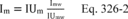
12.3 Calculate the correlation coefficient, slope, and intercepts for the calibration data using the least squares method for linear regression. Concentrations are expressed as the x-variable and response is expressed as the y-variable.
12.4 Calculate the concentration of isocyanate in the sample:
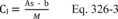
12.5 Calculate the total amount collected in the sample by multiplying the concentration (µg/ml) times the final volume of acetonitrile (10 ml).

12.6 Calculate the concentration of isocyanate (µg/dscm) in the stack gas.
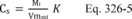
12.7 Calculate Relative Percent Difference (RPD) for each replicative sample
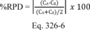
12.8 Calculate Field Train Spike Recovery
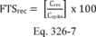
12.9 Calculate Percent Breakthrough
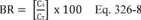 Where: K
= 35.314 ft 3/m 3 if Vm(std) is expressed in English units. = 1.00
m 3/m 3 if Vm(std) is expressed in metric units. 13.0 Method
Performance
Where: K
= 35.314 ft 3/m 3 if Vm(std) is expressed in English units. = 1.00
m 3/m 3 if Vm(std) is expressed in metric units. 13.0 Method
Performance
Evaluation of sampling and analytical procedures for a selected series of compounds must meet the quality control criteria (See Section 9) for each associated analytical determination. The sampling and analytical procedures must be challenged by the test compounds spiked at appropriate levels and carried through the procedures.
14.0 Pollution Prevention [Reserved] 15.0 Waste Management [Reserved] 16.0 Alternative Procedures [Reserved] 17.0 References 1. Martin, R.M., Construction Details of Isokinetic Source-Sampling Equipment, Research Triangle Park, NC, U.S. Environmental Protection Agency, April 1971, PB-203 060/BE, APTD-0581, 35 pp. 2. Rom, J.J., Maintenance, Calibration, and Operation of Isokinetic Source Sampling Equipment, Research Triangle Park, NC, U.S. Environmental Protection Agency, March 1972, PB-209 022/BE, APTD-0576, 39 pp. 3. Schlickenrieder, L.M., Adams, J.W., and Thrun, K.E., Modified Method 5 Train and Source Assessment Sampling System: Operator's Manual, U.S. Environmental Protection Agency, EPA/600/8-85/003/1985). 4. Shigehara, R.T., Adjustments in the EPA Nomograph for Different Pitot Tube Coefficients and Dry Molecular Weights, Stack Sampling News, 2:4-11 (October 1974). 5. U.S. Environmental Protection Agency, 40 CFR part 60, Appendices A-1, A-2, and A-3, Methods 1-5. 6. Vollaro, R.F., A Survey of Commercially Available Instrumentation for the Measurement of Low-Range Gas Velocities, Research Triangle Park, NC, U.S. Environmental Protection Agency, Emissions Measurement Branch, November 1976 (unpublished paper). 18.0 Diagrams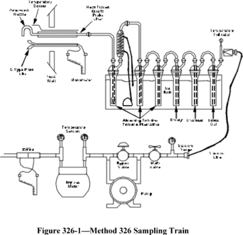 [57 FR 61992, Dec.
29, 1992] Editorial Note:For Federal Register citations affecting
appendix A to part 63, see the List of CFR Sections Affected, which
appears in the Finding Aids section of the printed volume and at
www.govinfo.gov.
[57 FR 61992, Dec.
29, 1992] Editorial Note:For Federal Register citations affecting
appendix A to part 63, see the List of CFR Sections Affected, which
appears in the Finding Aids section of the printed volume and at
www.govinfo.gov.Appendix B to Part 63 - Sources Defined for Early Reduction Provisions
40:16.0.1.1.1.46.325.36.123 : Appendix B
Appendix B to Part 63 - Sources Defined for Early Reduction Provisions| Source | Location of definition |
|---|---|
| 1. Organic Process Equipment in Volatile Hazardous Air Pollutant Service at Chemical Plants and Other Designated Facilities | 56 FR 9315, March 6, 1991, Announcement of Negotiated Rulemaking |
| a. All valves in gas or light liquid service within a process unit | |
| b. All pumps in light liquid service within a process unit | |
| c. All connectors in gas or light liquid service within a process unit | |
| d. Each compressor | |
| e. Each product accumulator vessel | |
| f. Each agitator | |
| g. Each pressure relief device | |
| h. Each open-ended valve or line | |
| i. Each sampling connection system | |
| j. Each instrumentation system | |
| k. Each pump, valve, or connector in heavy liquid service | |
| l. Each closed vent system and control device |
Appendix C to Part 63 - Determination of the Fraction Biodegraded (Fbio) in a Biological Treatment Unit
40:16.0.1.1.1.46.325.36.124 : Appendix C
Appendix C to Part 63 - Determination of the Fraction Biodegraded (Fbio) in a Biological Treatment Unit I. PurposeThe purpose of this appendix is to define the procedures for an owner or operator to use to calculate the site specific fraction of organic compounds biodegraded (Fbio) in a biological treatment unit. If an acceptable level of organic compounds is destroyed rather than emitted to the air or remaining in the effluent, the biological treatment unit may be used to comply with the applicable treatment requirements without the unit being covered and vented through a closed vent system to an air pollution control device.
The determination of Fbio shall be made on a system as it would exist under the rule. The owner or operator should anticipate changes that would occur to the wastewater flow and concentration of organics, to be treated by the biological treatment unit, as a result of enclosing the collection and treatment system as required by the rule.
Unless otherwise specified, the procedures presented in this appendix are designed to be applied to thoroughly mixed treatment units. A thoroughly mixed treatment unit is a unit that is designed and operated to approach or achieve uniform biomass distribution and organic compound concentration throughout the aeration unit by quickly dispersing the recycled biomass and the wastewater entering the unit. Detailed discussion on how to determine if a biological treatment unit is thoroughly mixed can be found in reference 7. Systems that are not thoroughly mixed treatment units should be subdivided into a series of zones that have uniform characteristics within each zone. The number of zones required to characterize a biological treatment system will depend on the design and operation of the treatment system. Detailed discussion on how to determine the number of zones in a biological treatment unit and examples of determination of f bio can be found in reference 8. Each zone should then be modeled as a separate unit. The amount of air emissions and biodegradation from the modeling of these separate zones can then be added to reflect the entire system.
II. DefinitionsBiological treatment unit = wastewater treatment unit designed and operated to promote the growth of bacteria to destroy organic materials in wastewater.
fbio = The fraction of individual applicable organic compounds in the wastewater biodegraded in a biological treatment unit. Fbio = The fraction of total applicable organic compounds in the wastewater biodegraded in a biological treatment unit. Fe = The fraction of applicable organic compounds emitted from the wastewater to the atmosphere. K1 = First order biodegradation rate constant, L/g MLVSS-hr KL = liquid-phase mass transfer coefficient, m/s M = compound specific mass flow weighted average of organic compounds in the wastewater, Mg/Yr III. Procedures for Determination of fbioThe first step in the analysis to determine if a biological treatment unit may be used without being covered and vented through a closed-vent system to an air pollution control device is to determine the compound-specific fbio. The following procedures may be used to determine fbio:
(1) The EPA Test Method 304A or 304B (appendix A, part 63) - Method for the Determination of Biodegradation Rates of Organic Compounds,
(2) Performance data with and without biodegradation,
(3) Inlet and outlet concentration measurements,
(4) Batch tests,
(5) Multiple zone concentration measurements.
All procedures must be executed so that the resulting fbio is based on the collection system and waste management units being in compliance with the rule. If the collection system and waste management units meet the suppression requirements at the time of the test, any of the procedures may be chosen. If the collection system and waste management units are not in compliance at the time of the performance test, then only Method 304A, B, or the batch test shall be chosen. If Method 304A, B, or the batch test is used, any anticipated changes to the influent of the full-scale biological treatment unit that will occur after the facility has enclosed the collection system must be represented in the influent feed to the benchtop bioreactor unit, or test unit.
Select one or more appropriate procedures from the five listed above based on the availability of site specific data and the type of mixing that occurs in the unit (thoroughly mixed or multiple mixing zone). If the facility does not have site-specific data on the removal efficiency of its biological treatment unit, then Procedure 1 or Procedure 4 may be used. Procedure 1 allows the use of a benchtop bioreactor to determine the first-order biodegradation rate constant. An owner or operator may elect to assume the first order biodegradation rate constant is zero for any regulated compound(s) present in the wastewater. Procedure 4 explains two types of batch tests which may be used to estimate the first order biodegradation rate constant. An owner or operator may elect to assume the first order biodegradation rate constant is zero for any regulated compound(s) present in the wastewater. Procedure 3 would be used if the facility has, or measures to determine, data on the inlet and outlet individual organic compound concentration for the biological treatment unit. Procedure 3 may only be used on a thoroughly mixed treatment unit. Procedure 5 is the concentration measurement test that can be used for units with multiple mixing zones. Procedure 2 is used if a facility has or obtains performance data on a biotreatment unit prior to and after addition of the microbial mass. An example where Procedure 2 could be used is an activated sludge unit where measurements have been taken on inlet and exit concentration of organic compounds in the wastewater prior to seeding with the microbial mass and startup of the unit. The flow chart in figure 1 outlines the steps to use for each of the procedures.
A. Method 304A or 304B (Procedure 1)If the first procedure is selected, follow the instructions in appendix A of part 63 Method 304A “Method for the Determination of Biodegradation Rates of Organic Compounds (Vented Option)” or Method 304B “Method for the Determination of Biodegradation Rates of Organic Compounds (Scrubber Option).” Method 304A or 304B provides instruction on setting up and operating a self-contained benchtop bioreactor system which is operated under conditions representative of the target full-scale system. Method 304A uses a benchtop bioreactor system with a vent, and uses modeling to estimate any air emissions. Method 304B uses a benchtop bioreactor system which is equipped with a scrubber and is not vented.
There are some restrictions on which method a source may use. If the facility is measuring the rate of biodegradation of compounds that may tend to react or hydrolyze in the scrubber of Method 304B, this method shall not be used and Method 304A is the required method. If a Henry's law value is not available to use with Form V, then Method 304A shall not be used and Method 304B is the required method. When using either method, the feed flow to the benchtop bioreactor shall be representative of the flow and concentration of the wastewater that will be treated by the full-scale biological treatment unit after the collection and treatment system has been enclosed as required under the applicable subpart.
The conditions under which the full-scale biological treatment unit is run establish the operating parameters of Method 304A or 304B. If the biological treatment unit is operated under abnormal operating conditions (conditions outside the range of critical parameters examined and confirmed in the laboratory), the EPA believes this will adversely affect the biodegradation rate and is an unacceptable treatment option. The facility would be making multiple runs of the test method to simulate the operating range for its biological treatment unit. For wide ranges of variation in operating parameters, the facility shall demonstrate the biological treatment unit is achieving an acceptable level of control, as required by the regulation, across the ranges and not only at the endpoints.
If Method 304A is used, complete Form V initially. Form V is used to calculate K1 from the Method 304A results. Form V uses the Henry's law constant to estimate the fraction lost from the benchtop reactor vent. The owner or operator shall use the Henry's law values in Table I. Form V also gives direction for calculating an equivalent KL. Note on Form V if the calculated number for line 11 is greater than the calculated value for line 13, this procedure shall not be used to demonstrate the compound is biodegradable. If line 11 is greater than line 13, this is an indication the fraction emitted from the vent is greater than the fraction biodegraded. The equivalent KL determined on Form V is used in Form II (line 6). Estimation of the Fe and fbio must be done following the steps in Form III. Form III uses the previously calculated values of K1 and KL (equivalent KL), and site-specific parameters of the full-scale bioreactor as input to the calculations. Forms II, III, and V must be completed for each organic compound in the wastewater to determine Fe and fbio.
If Method 304B is used, perform the method and use the measurements to determine K1, which is the first-order biodegradation rate constant. Form I lists the sequence of steps in the procedure for calculating K1 from the Method 304B results. Once K1 is determined, KL must be calculated by use of mass transfer equations. Form II outlines the procedure to follow for use of mass transfer equations to determine KL. A computer program which incorporates these mass transfer equations may be used. Water7 is a program that incorporates these mass transfer equations and may be used to determine KL. Refer to Form II-A to determine KL, if Water7 or the most recent update to this model is used. In addition, the Bay Area Sewage Toxics Emission (BASTE) model version 3.0 or equivalent upgrade and the TOXCHEM (Environment Canada's Wastewater Technology Centre and Environmega, Ltd.) model version 1.10 or equivalent upgrade may also be used to determine KL for the biological treatment unit with several stipulations. The programs must be altered to output a KL value which is based on the site-specific parameters of the unit modeled, and the Henry's law values listed in Table I must be substituted for the existing Henry's law values in the programs. Input values used in the model and corresponding output values shall become documentation of the fbio determination. The owner or operator should be aware these programs do not allow modeling of certain units. To model these units, the owner or operator shall use one of the other appropriate procedures as outlined in this appendix. The owner or operator shall not use a default value for KL. The KL value determined by use of these models shall be based on the site-specific parameters of the specific unit. This KL value shall be inserted in Form II (line 6). Estimation of the Fe and fbio must be done following the steps in Form III. Form III uses the previously calculated values of K1 and KL, and site-specific parameters of the full-scale bioreactor as input to the calculations. Forms I, II, and III must be completed for each organic compound in the wastewater to determine Fe and fbio.
B. Performance Data With and Without Biodegradation (Procedure 2)Procedure 2 uses site-specific performance data that represents or characterizes operation of the unit both with and without biodegradation. As previously mentioned, proper determination of fbio must be made on a system as it would exist under the rule. Using Form IV, calculate KL and K1. After KL and K1 are determined, Form III is used to calculate Fe and fbio for each organic compound present in the wastewater.
C. Inlet and Outlet Concentration Measurements (Procedure 3)Procedure 3 uses measured inlet and outlet organic compound concentrations for the unit. This procedure may only be used on a thoroughly mixed treatment unit. Again, proper determination of fbio must be made on a system as it would exist under the rule. The first step in using this procedure is to calculate KL using Form II. A computer model may be used. If the Water7 model or the most recent update to this model is used, then use Form II-A to calculate KL. After KL is determined using field data, complete Form VI to calculate K1. The TOXCHEM or BASTE model may also be used to calculate KL for the biological treatment unit, with the stipulations listed in procedure 304B. After KL and K1 are determined, Form III is used to calculate Fe and fbio for each organic compound.
D. Batch Tests (Procedure 4)Two types of batch tests which may be used to determine kinetic parameters are: (1) The aerated reactor test and (2) the sealed reactor test. The aerated reactor test is also known as the BOX test (batch test with oxygen addition). The sealed reactor test is also known as the serum bottle test. These batch tests should be conducted only by persons familiar with procedures for determining biodegradation kinetics. Detailed discussions of batch procedures for determining biodegradation kinetic parameters can be found in references 1-4.
For both batch test approaches, a biomass sample from the activated sludge unit of interest is collected, aerated, and stored for no more than 4 hours prior to testing. To collect sufficient data when biodegradation is rapid, it may be necessary to dilute the biomass sample. If the sample is to be diluted, the biomass sample shall be diluted using treated effluent from the activated sludge unit of interest to a concentration such that the biodegradation test will last long enough to make at least six concentration measurements. It is recommended that the tests not be terminated until the compound concentration falls below the limit of quantitation (LOQ). Measurements that are below the LOQ should not be used in the data analysis. Biomass concentrations shall be determined using standard methods for measurement of mixed liquor volatile suspended solids (MLVSS) (reference 5).
The change in concentration of a test compound may be monitored by either measuring the concentration in the liquid or in the reactor headspace. The analytical technique chosen for the test should be as sensitive as possible. For the batch test procedures described in this section, equilibrium conditions must exist between the liquid and gas phases of the experiments because the data analysis procedures are based on this premise. To use the headspace sampling approach, the reactor headspace must be in equilibrium with the liquid so that the headspace concentrations can be correlated with the liquid concentrations. Before the biodegradation testing is conducted, the equilibrium assumption must be verified. A discussion of the equilibrium assumption verification is given below in sections D.1 and D.2 since different approaches are required for the two types of batch tests.
To determine biodegradation kinetic parameters in a batch test, it is important to choose an appropriate initial substrate (compound(s) of interest) concentration for the test. The outcome of the batch experiment may be influenced by the initial substrate (SO) to biomass (XO) ratio (see references 3, 4, and 6). This ratio is typically measured in chemical oxygen demand (COD) units. When the SO/XO ratio is low, cell multiplication and growth in the batch test is negligible and the kinetics measured by the test are representative of the kinetics in the activated sludge unit of interest. The SO/XO ratio for a batch test is determined with the following equation:
Where: SO/XO = initial substrate to biomass ratio on a COD basis Si = initial substrate concentration in COD units (g COD/L) X = biomass concentration in the batch test (g MLVSS/L) 1.42 = Conversion factor to convert to COD unitsFor the batch tests described in this section, the SO/XO ratio (on a COD basis) must be initially less than 0.5.
1. Aerated Reactor Test. An aerated draft tube reactor may be used for the biokinetics testing (as an example see Figure 2 of appendix C). Other aerated reactor configurations may also be used. Air is bubbled through a porous frit at a rate sufficient to aerate and keep the reactor uniformly mixed. Aeration rates typically vary from 50 to 200 ml/min for a 1 liter system. A mass flow rate controller is used to carefully control the air flow rate because it is important to have an accurate measure of this rate. The dissolved oxygen (DO) concentration in the system must not fall below 2 mg/liter so that the biodegradation observed will not be DO-limited. Once the air flow rate is established, the test mixture (or compound) of interest is then injected into the reactor and the concentration of the compound(s) is monitored over time. Concentrations may be monitored in the liquid or in the headspace. A minimum of six samples shall be taken over the period of the test. However, it is necessary to collect samples until the compound concentration falls below the LOQ. If liquid samples are collected, they must be small enough such that the liquid volume in the batch reactor does not change by more than 10%.
Before conducting experiments with biomass, it is necessary to verify the equilibrium assumption. The equilibrium assumption can be verified by conducting a stripping experiment using the effluent (no biomass) from the activated sludge unit of interest. Effluent is filtered with a 0.45 um or smaller filter and placed in the draft tube reactor. Air is sparged into the system and the compound concentration in the liquid or headspace is monitored over time. This test with no biomass may provide an estimate of the Henry's law constant. If the system is at equilibrium, the Henry's law constant may be estimated with the following equation:
Where: C = cencentration at time, t (min) CO = concentration at t = 0 G = volumetric gas flow rate (ml/min) V = liquid volume in the batch reactor (ml) Keq = Henry's law constant (mg/L-gas)/(mg/L-liquid) t = time (min)A plot of - ln(C/Co) as a function of t will have a slope equal to GKeq/V. The equilibrium assumption can be verified by comparing the experimentally determined Keq for the system to literature values of the Henry's Law constant (including those listed in this appendix). If Keq does not match the Henry's law constant, Keq shall be determined from analysis of the headspace and liquid concentration in a batch system.
The concentration of a compound decreases in the bioreactor due to both biodegradation and stripping. Biodegradation processes are typically described with a Monod model. This model and a stripping expression are combined to give a mass balance for the aerated draft tube reactor):
Where: s = test compound concentration, mg/liter G = volumetric gas flow rate, liters/hr Keq = Henry's Law constant measured in the system, (mg/liter gas)/(mg/liter liquid) V = volume of liquid in the reactor, liters X = biomass concentration (g MLVSS/liter) Qm = maximum rate of substrate removal, mg/g MLVSS/hr KS = Monod biorate constant at half the maximum rate, mg/literEquation App. C-3 can be integrated to obtain the following equation:
Where: A = GKeqKs + QmVX B = GKeq So = test compound concentration at t = 0This equation is used along with the substrate concentration versus time data to determine the best fit parameters (Qm and KS) to describe the biodegradation process in the aerated reactor. If the aerated reactor test is used, the following procedure is used to analyze the data. Evaluate Keq for the compound of interest with Form XI. The concentration in the vented headspace or liquid is measured as a function of time and the data is entered on Form XI. A plot is made from the data and attached to the Form XI. Keq is calculated on Form XI and the results are contrasted with the expected value of Henry's law obtained from Form IX. If the comparison is satisfactory, the stripping constant is calculated from Keq, completing Form XI. The values of Keq may differ because the theoretical value of Keq may not be applicable to the system of interest. If the comparison of the calculated Keq from the form and the expected value of Henry's law is unsatisfactory, Form X can alternatively be used to validate Keq. If the aerated reactor is demonstrated to not be at equilibrium, either modify the reactor design and/or operation, or use another type of batch test.
The compound-specific biorate constants are then measured using Form XII. The stripping constant that was determined from Form XI and a headspace correction factor of 1 are entered on Form XII. The aerated reactor biotest may then be run, measuring concentrations of each compound of interest as a function of time. If headspace concentrations are measured instead of liquid concentrations, then the corresponding liquid concentrations are calculated from the headspace measurements using the Keq determined on Form XI and entered on Form XII.
The concentration data on Form XII may contain scatter that can adversely influence the data interpretation. It is possible to curve fit the concentration data and enter the concentrations on the fitted curve instead of the actual data. If curve fitting is used, the curve-fitting procedure must be based upon the Equation App. C-4. When curve fitting is used, it is necessary to attach a plot of the actual data and the fitted curve to Form XII.
If the stripping rate constant is relatively large when compared to the biorate at low concentrations, it may be difficult to obtain accurate evaluations of the first-order biorate constant. In these cases, either reducing the stripping rate constant by lowering the aeration rate, or increasing the biomass concentrations should be considered.
The final result of the batch testing is the measurement of a biorate that can be used to estimate the fraction biodegraded, fbio. The number transferred to Form III is obtained from Form XII, line 9.
2. Sealed Reactor Test. This test uses a closed system to prevent losses of the test compound by volatilization. This test may be conducted using a serum bottle or a sealed draft tube reactor (for an example see Figure 3 of appendix C). Since no air is supplied, it is necessary to ensure that sufficient oxygen is present in the system. The DO concentration in the system must not fall below 2 mg/liter so that the biodegradation observed will not be DO-limited. As an alternative, oxygen may be supplied by electrolysis as needed to maintain the DO concentration above 2 mg/liter. The reactor contents must be uniformly mixed, by stirring or agitation using a shaker or similar apparatus. The test mixture (or compound) of interest is injected into the reactor and the concentration is monitored over time. A minimum of six samples shall be taken over the period of the test. However, it is necessary to monitor the concentration until it falls below the LOQ.
The equilibrium assumption must be verified for the batch reactor system. In this case, Keq may be determined by simultaneously measuring gas and liquid phase concentrations at different times within a given experiment. A constant ratio of gas/liquid concentrations indicates that equilibrium conditions are present and Keq is not a function of concentration. This ratio is then taken as the Keq for the specific compound in the test. It is not necessary to measure Keq for each experiment. If the ratio is not constant, the equilibrium assumption is not valid and it is necessary to (1) increase mixing energy for the system and retest for the equilibrium assumption, or (2) use a different type of test (for example, a collapsible volume reactor).
The concentration of a compound decreases in the bioreactor due to biodegradation according to Equation App. C-5:
Where: s = test compound concentration (mg/liters) Vl = the average liquid volume in the reactor (liters) Vg = the average gas volume in the reactor (liters) Qm = maximum rate of substrate removal (mg/g ML VSS/hr) Keq = Henry's Law constant determined for the test, (mg/liter gas)/(mg/liter liquid) Ks = Monod biorate constant at one-half the maximum rate (mg/liter) t = time (hours) X = biomass concentration (g ML VSS/liter) so = test compound concentration at time t = 0Equation App. C-5 can be solved analytically to give:
This equation is used along with the substrate concentration versus time data to determine the best fit parameters (Qm and Ks) to describe the biodegradation process in the sealed reactor.
If the sealed reactor test is used, Form X is used to determine the headspace correction factor. The disappearance of a compound in the sealed reactor test is slowed because a fraction of the compound is not available for biodegradation because it is present in the headspace. If the compound is almost entirely in the liquid phase, the headspace correction factor is approximately one. If the headspace correction factor is substantially less than one, improved mass transfer or reduced headspace may improve the accuracy of the sealed reactor test. A preliminary sealed reactor test must be conducted to test the equilibrium assumption. As the compound of interest is degraded, simultaneous headspace and liquid samples should be collected and Form X should be used to evaluate Keq. The ratio of headspace to liquid concentrations must be constant in order to confirm that equilibrium conditions exist. If equilibrium conditions are not present, additional mixing or an alternate reactor configuration may be required.
The compound-specific biorate constants are then calculated using Form XII. For the sealed reactor test, a stripping rate constant of zero and the headspace correction factor that was determined from Form X are entered on Form XII. The sealed reactor test may then be run, measuring the concentrations of each compound of interest as a function of time. If headspace concentrations are measured instead of liquid concentrations, then the corresponding liquid concentrations are calculated from the headspace measurements using Keq from Form X and entered on Form XII.
The concentration data on Form XII may contain scatter that can adversely influence the data interpretation. It is possible to curve fit the concentration data and enter the concentrations on the fitted curve instead of the actual data. If curve fitting is used, the curve-fitting procedure must be based upon Equation App. C-6. When curve fitting is used, it is necessary to attach a plot of the actual data and the fitted curve to Form XII.
If a sealed collapsible reactor is used that has no headspace, the headspace correction factor will equal 1, but the stripping rate constant may not equal 0 due to diffusion losses through the reactor wall. The ratio of the rate of loss of compound to the concentration of the compound in the reactor (units of per hour) must be evaluated. This loss ratio has the same units as the stripping rate constant and may be entered as the stripping rate constant on line 1 of Form XII.
If the loss due to diffusion through the walls of the collapsible reactor is relatively large when compared to the biorate at low concentrations, it may be difficult to obtain accurate evaluations of the first-order biorate constant. In these cases, either replacing the materials used to construct the reactor with materials of low permeability or increasing the biomass concentration should be considered.
The final result of the batch testing is the measurement of a biorate that can be used to estimate the fraction biodegraded, fbio. The number transferred to Form III is obtained from Form XII, line 9.
The number on Form XII line 9 will equal the Monod first-order biorate constant if the full-scale system is operated in the first-order range. If the full-scale system is operated at concentrations above that of the Monod first-order range, the value of the number on line 9 will be somewhat lower than the Monod first-order biorate constant. With supporting biorate data, the Monod model used in Form XII may be used to estimate the effective biorate constant K1 for use in Form III.
If a reactor with headspace is used, analysis of the data using equation App. C-6 is valid only if Vl and Vg do not change more than 10% (i.e., they can be approximated as constant for the duration of the test). Since biodegradation is occurring only in the liquid, as the liquid concentration decreases it is necessary for mass to transfer from the gas to the liquid phase. This may require vigorous mixing and/or reducing the volume in the headspace of the reactor.
If there is no headspace (e.g., a collapsible reactor), equation App. C-6 is independent of V1 and there are no restrictions on the liquid volume. If a membrane or bag is used as the collapsible-volume reactor, it may be important to monitor for diffusion losses in the system. To determine if there are losses, the bag should be used without biomass and spiked with the compound(s) of interest. The concentration of the compound(s) in the reactor should be monitored over time. The data are analyzed as described above for the sealed reactor test.
3. Quality Control/Quality Assurance (QA/QC). A QA/QC plan outlining the procedures used to determine the biodegradation rate constants shall be prepared and a copy maintained at the source. The plan should include, but may not be limited to:
1. A description of the apparatus used (e.g., size, volume, method of supplying air or oxygen, mixing, and sampling procedures) including a simplified schematic drawing.
2. A description of how biomass was sampled from the activated sludge unit.
3. A description of how biomass was held prior to testing (age, etc.).
4. A description of what conditions (DO, gas-liquid equilibrium, temperature, etc.) are important, what the target values are, how the factors were controlled, and how well they were controlled.
5. A description of how the experiment was conducted, including preparation of solutions, dilution procedures, sampling procedures, monitoring of conditions, etc.
6. A description of the analytical instrumentation used, how the instruments were calibrated, and a summary of the precision for that equipment.
7. A description of the analytical procedures used. If appropriate, reference to an ASTM, EPA or other procedure may be used. Otherwise, describe how the procedure is done, what is done to measure precision, accuracy, recovery, etc., as appropriate.
8. A description of how data are captured, recorded, and stored.
9. A description of the equations used and their solutions, including a reference to any software used for calculations and/or curve-fitting.
E. Multiple Zone Concentration Measurements (Procedure 5)Procedure 5 is the concentration measurement method that can be used to determine the fbio for units that are not thoroughly mixed and thus have multiple zones of mixing. As with the other procedures, proper determination of fbio must be made on a system as it would exist under the rule. For purposes of this calculation, the biological unit must be divided 1 into zones with uniform characteristics within each zone. The number of zones that is used depends on the complexity of the unit. Reference 8, “Technical Support Document for the Evaluation of Aerobic Biological Treatment Units with Multiple Mixing Zones,” is a source for further information concerning how to determine the number of zones that should be used for evaluating your unit. The following information on the biological unit must be available to use this procedure: basic unit variables such as inlet and recycle wastewater flow rates, type of agitation, and operating conditions; measured representative organic compound concentrations in each zone and the inlet and outlet; and estimated mass transfer coefficients for each zone.
1 This is a mathematical division of the actual unit; not addition of physical barriers.
Reference 8 “Technical Support Document for the Evaluation of Aerobic Biological Treatment Units with Multiple Mixing Zones,” is a source for further information concerning how to interpolate the biorates for multiple zones. In units with well-characterized concentration measurements obtained in an initial evaluation of the unit, it may be possible to demonstrate that there is a good correlation of the component concentrations with the locations in the multiple-zone unit. With this good correlation, it may be possible to accurately predict the concentrations in selected zones without actually testing each selected zone. This correlation method may be used for units that have many zones (greater than 5) or where one of the interior zones is not readily accessible for sampling. To use this correlation method of estimating zone concentrations, it is necessary to measure the concentrations in the inlet unit, the exit unit, and sufficient interior units to obtain a correlation of component concentrations with the locations. You cannot use this correlation method of estimating selected zone concentrations if monitoring of each zone is required, or if the accuracy and precision of the correlation is inferior to actual individual sampling error. The accuracy and precision of the correlation may be improved by increasing the number of locations tested. Because the correlation is based on many samples, it should provide an accurate representation of a stable operating system.
The estimated mass transfer coefficient for each compound in each zone is obtained from Form II using the characteristics of each zone. A computer model may be used. If the Water7 model or the most recent update to this model is used, then use Form II-A to calculate KL. The TOXCHEM or BASTE model may also be used to calculate KL for the biological treatment unit, with the stipulations listed in Procedure 304B. Compound concentration measurements for each zone are used in Form XIII to calculate the fbio. A copy of Form XIII is completed for each of the compounds of concern treated in the biological unit.
IV. Calculation of FbioAt this point, the individual fbios determined by the previously explained procedures must be summed to obtain the total Fbio. To determine the Fbio multiply each compound specific fbio by the compound-specific average mass flow rate of the organic compound in the wastewater stream (see regulation for instruction on calculation of average mass flow rate). Sum these products and divide by the total wastewater stream average mass flow rate of organic compounds.
M = compound specific average mass flow rate of the organic compounds in the wastewater (Mg/Yr) n = number of organic compounds in the wastewaterThe Fbio is then used in the applicable compliance equations in the regulation to determine if biodegradation may be used to comply with the treatment standard without covering and venting to an air pollution control device.
References1. Rajagopalan, S. et al. “Comparison of Methods for Determining Biodegradation Kinetics of Volatile Organic Compounds.” Proceedings of Water Environment Federation. 67th Annual Conference, October 15-19, 1994.
2. Ellis, T.G. et al. “Determination of Toxic Organic Chemical Biodegradation Kinetics Using Novel Respirometric Technique”. Proceedings Water Environment Federation, 67th Annual Conference, October 15-19, 1994.
3. Pitter, P. and J. Chudoba. Biodegradability of Organic Substances in the Aquatic Environment. CRC Press, Boca Raton, FL. 1990.
4. Grady, C.P.L., B. Smets, and D. Barbeau. Variability in kinetic parameter estimates: A review of possible causes and a proposed terminology. Wat. Res. 30 (3), 742-748, 1996.
5. Eaton, A.D., et al. eds., Standard Methods for the Examination of Water and Wastewater, 19th Edition, American Public Health Association, Washington, DC, 1995.
6. Chudoba P., B. Capdeville, and J. Chudoba. Explanation of biological meaning of the So/Xo ratio in batch cultivation. Wat. Sci. Tech. 26 (3/4), 743-751, 1992.
7. Technical Support Document for Evaluation of Thoroughly Mixed Biological Treatment Units. November 1998.
8. Technical Support Document for the Evaluation of Aerobic Biological Treatment Units with Multiple Mixing Zones. July 1999.
Table I
| Compound | HL @ 25 °C (atm/mole frac) | HL @ 100 °C (atm/mole frac) |
|---|---|---|
| 1 Acetaldehyde | 4.87e + 00 | 5.64e + 01 |
| 3 Acetonitrile | 1.11e + 00 | 1.78e + 01 |
| 4 Acetophenone | 5.09e−01 | 2.25e + 01 |
| 5 Acrolein | 4.57e + 00 | 6.61e + 01 |
| 8 Acrylonitrile | 5.45e + 00 | 6.67e + 01 |
| 9 Allyl chloride | 5.15e + 02 | 2.26e + 03 |
| 10 Aniline | 9.78e−02 | 1.42e + 00 |
| 12 Benzene | 3.08e + 02 | 1.93e + 03 |
| 14 Benzyl chloride | 1.77e + 01 | 2.88e + 02 |
| 15 Biphenyl | 2.27e + 01 | 1.27e + 03 |
| 17 Bromoform | 2.96e + 01 | 3.98e + 02 |
| 18 1,3-Butadiene | 3.96e + 03 | 1.56e + 04 |
| 20 Carbon disulfide | 1.06e + 03 | 3.60e + 03 |
| 21 Carbon tetrachloride | 1.68e + 03 | 1.69e + 04 |
| 23 2-Chloroacetophenone | 4.84e−02 | 1.43e + 01 |
| 24 Chlorobenzene | 2.09e + 02 | 3.12e + 03 |
| 25 Chloroform | 2.21e + 02 | 1.34e + 03 |
| 26 Chloroprene | 5.16e + 01 | 1.74e + 02 |
| 29 o-Cresol | 9.12e−02 | 2.44e + 01 |
| 31 Cumene | 7.28e + 02 | 7.15e + 03 |
| 32 1,4-Dichlorobenzene(p) | 1.76e + 02 | 1.95e + 03 |
| 33 Dichloroethyl ether | 1.14e + 00 | 3.57e + 01 |
| 34 1,3-Dichloropropene | 1.97e + 02 | 1.44e + 03 |
| 36 N,N-Dimethylaniline | 7.70e−01 | 5.67e + 02 |
| 37 Diethyl sulfate | 3.41e−01 | 4.22e + 01 |
| 38 3,3′-Dimethylbenzidine | 7.51e−05 | 5.09e−01 |
| 40 1,1-Dimethylhydrazine | 9.11e−02 | 1.57e + 01 |
| 42 Dimethyl sulfate | 2.23e−01 | 1.43e + 01 |
| 43 2,4-Dinitrophenol | 2.84e−01 | 1.50e + 02 |
| 44 2,4-Dinitrotoluene | 4.00e−01 | 9.62e + 00 |
| 45 1,4-Dioxane | 3.08e−01 | 9.53e + 00 |
| 47 Epichlorohydrin | 1.86e + 00 | 4.34e + 01 |
| 48 Ethyl acrylate | 1.41e + 01 | 3.01e + 02 |
| 49 Ethylbenzene | 4.38e + 02 | 4.27e + 03 |
| 50 Ethyl chloride (chloroethane) | 6.72e + 02 | 3.10e + 03 |
| 51 Ethylene dibromide | 3.61e + 01 | 5.15e + 02 |
| 52 Ethylene dichloride (1,2-Dichloroethane) | 6.54e + 01 | 5.06e + 02 |
| 54 Ethylene oxide | 1.32e + 01 | 9.09e + 01 |
| 55 Ethylidene dichloride (1,1-Dichloroethane) | 3.12e + 02 | 2.92e + 03 |
| 57 Ethylene glycol dimethyl ether | 1.95e + 00 | 4.12e + 01 |
| 60 Ethylene glycol monoethyl ether acetate | 9.86e−02 | 6.03e + 00 |
| 62 Ethylene glycol monomethyl ether acetate | 1.22e−01 | 6.93e + 00 |
| 64 Diethylene glycol dimethyl ether | 8.38e−02 | 4.69e + 00 |
| 69 Diethylene glycol diethyl ether | 1.19e−01 | 7.71e + 00 |
| 72 Ethylene glycol monobutyl ether acetate | 2.75e−01 | 2.50e + 01 |
| 73 Hexachlorobenzene | 9.45e + 01 | 2.57e + 04 |
| 74 Hexachlorobutadiene | 5.72e + 02 | 6.92e + 03 |
| 75 Hexachloroethane | 4.64e + 02 | 7.49e + 04 |
| 76 Hexane | 4.27e + 04 | 9.44e + 04 |
| 78 Isophorone | 3.68e−01 | 1.68e + 01 |
| 80 Methanol | 2.89e−01 | 7.73e + 00 |
| 81 Methyl bromide (Bromomethane) | 3.81e + 02 | 2.12e + 03 |
| 82 Methyl chloride (Chloromethane) | 4.90e + 02 | 2.84e + 03 |
| 83 Methyl chloroform (1,1,1-Trichloroethane) | 9.67e + 02 | 5.73e + 03 |
| 84 Methyl ethyl ketone (2-Butanone) | 7.22e + 00 | 5.92e + 01 |
| 86 Methyl isobutyl ketone (Hexone) | 2.17e + 01 | 3.72e + 02 |
| 88 Methyl methacrylate | 7.83e + 00 | 9.15e + 01 |
| 89 Methyl tert-butyl ether | 3.08e + 01 | 2.67e + 02 |
| 90 Methylene chloride (Dichloromethane) | 1.64e + 02 | 9.15e + 02 |
| 93 Naphthalene | 2.68e + 01 | 7.10e + 02 |
| 94 Nitrobenzene | 1.33e + 00 | 2.80e + 01 |
| 96 2-Nitropropane | 6.61e + 00 | 8.76e + 01 |
| 99 Phosgene | 7.80e + 02 | 3.51e + 03 |
| 102 Propionaldehyde | 3.32e + 00 | 1.42e + 02 |
| 103 Propylene dichloride | 1.59e + 02 | 1.27e + 03 |
| 104 Propylene oxide | 1.98e + 01 | 1.84e + 02 |
| 106 Styrene | 1.45e + 02 | 1.72e + 03 |
| 107 1,1,2,2-Tetrachloroethane | 1.39e + 01 | 1.99e + 02 |
| 108 Tetrachloroethylene (Perchloroethylene) | 9.83e + 02 | 1.84e + 04 |
| 109 Toluene | 3.57e + 02 | 2.10e + 03 |
| 112 o-Toluidine | 1.34e−01 | 1.15e + 01 |
| 113 1,2,4-Trichlorobenzene | 1.07e + 02 | 1.04e + 03 |
| 114 1,1,2-Trichloroethane | 4.58e + 01 | 5.86e + 02 |
| 115 Trichloroethylene | 5.67e + 02 | 7.66e + 03 |
| 116 2,4,5-Trichlorophenol | 4.84e−01 | 6.27e + 01 |
| 117 Triethylamine | 6.94e + 00 | 2.57e + 02 |
| 118 2,2,4-Trimethylpentane | 1.85e + 05 | 9.74e + 05 |
| 119 Vinyl acetate | 2.82e + 01 | 2.80e + 02 |
| 120 Vinyl chloride | 1.47e + 03 | 6.45e + 03 |
| 121 Vinylidene chloride (1,1-Dichloroethylene) | 1.44e + 03 | 1.40e + 04 |
| 123 m-Xylene | 4.13e + 02 | 3.25e + 03 |
| 124 o-Xylene | 2.71e + 02 | 2.55e + 03 |
| 125 p-Xylene | 4.13e + 02 | 3.20e + 03 |
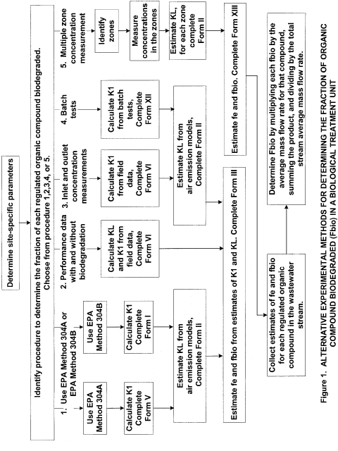
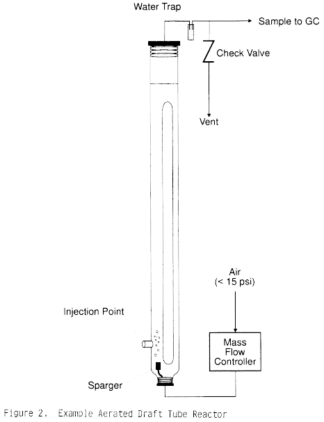
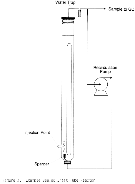
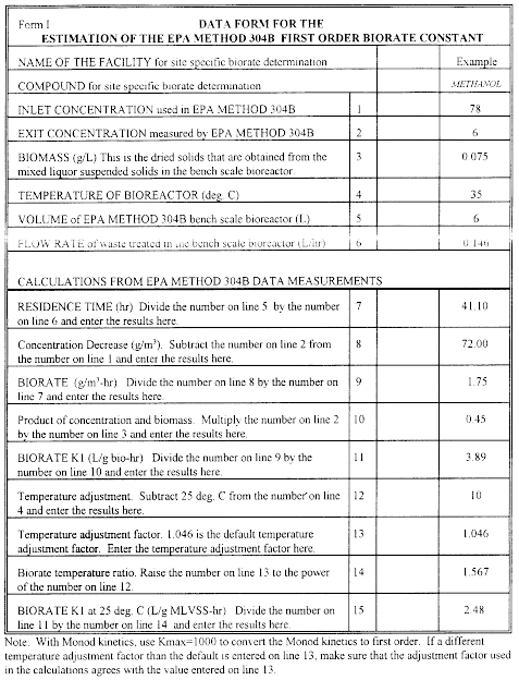
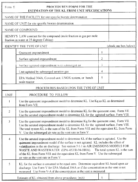
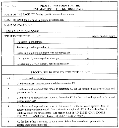
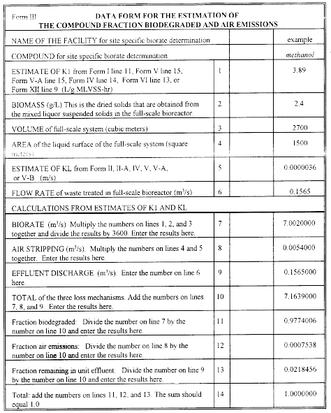
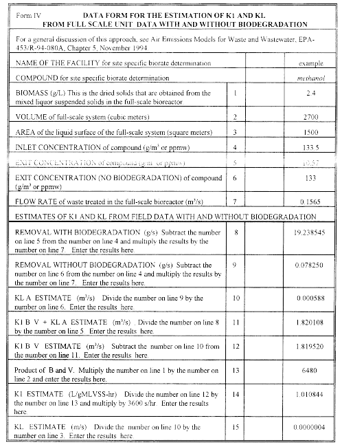
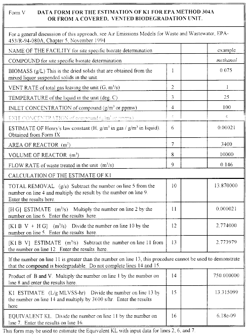
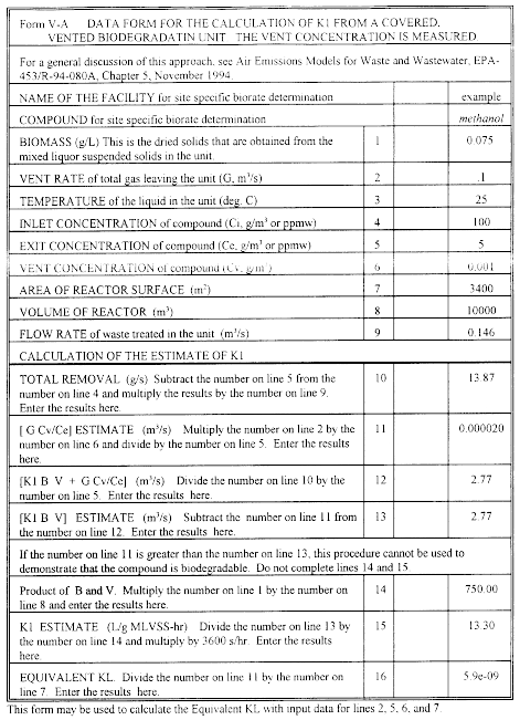
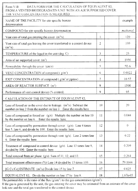
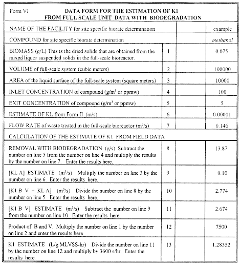
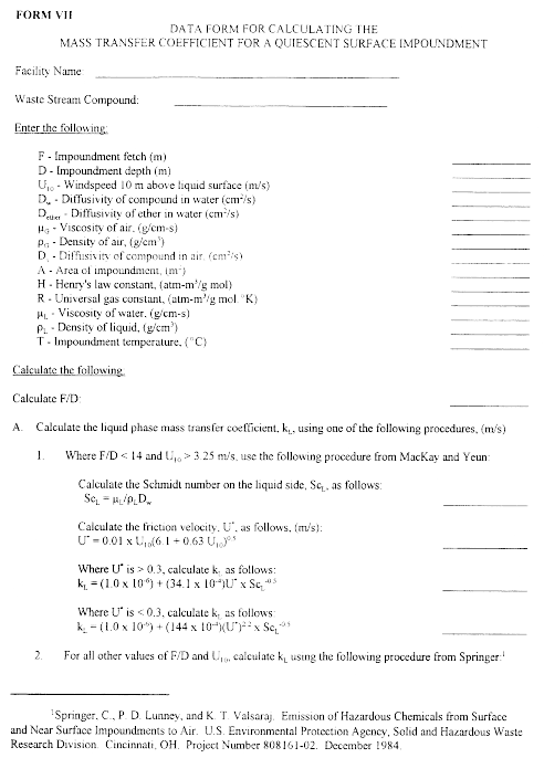
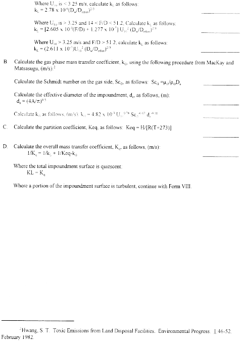
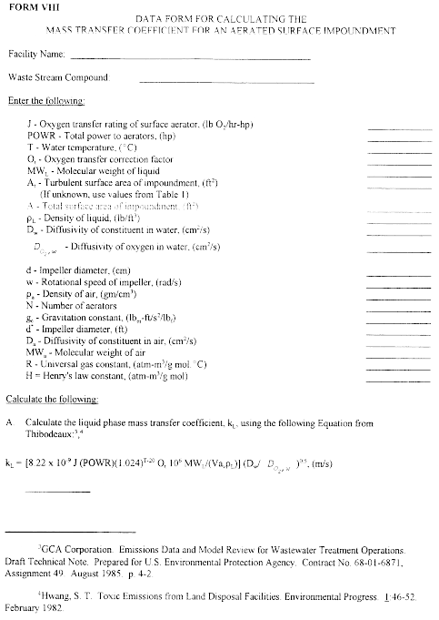
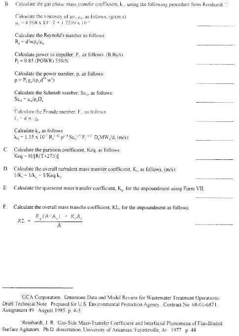
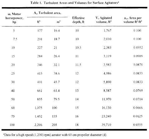
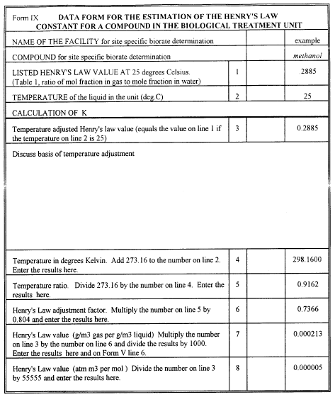
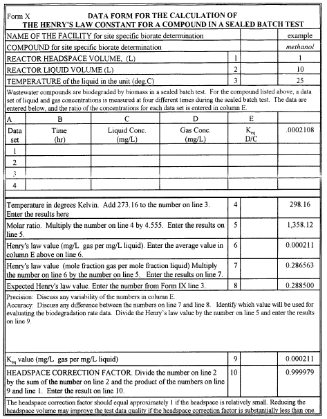
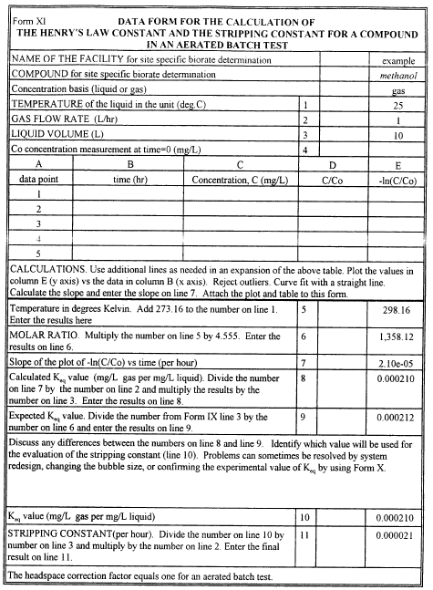
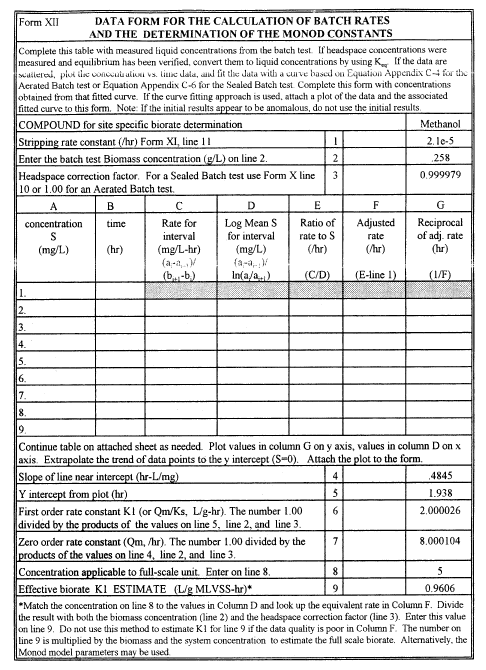
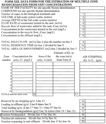 [62 FR 2801, Jan.
17, 1997, as amended at 63 FR 67794, Dec. 9, 1998; 66 FR 6935, Jan.
22, 2001]
[62 FR 2801, Jan.
17, 1997, as amended at 63 FR 67794, Dec. 9, 1998; 66 FR 6935, Jan.
22, 2001]Appendix D to Part 63 - Alternative Validation Procedure for EPA Waste and Wastewater Methods
40:16.0.1.1.1.46.325.36.125 : Appendix D
Appendix D to Part 63 - Alternative Validation Procedure for EPA Waste and Wastewater Methods 1. ApplicabilityThis procedure is to be applied exclusively to Environmental Protection Agency methods developed by the Office of Water and the Office of Resource Conservation and Recovery. Alternative methods developed by any other group or agency shall be validated according to the procedures in Sections 5.1 and 5.3 of Test Method 301, 40 CFR part 63, appendix A. For the purposes of this appendix, “waste” means waste and wastewater.
2. ProcedureThis procedure shall be applied once for each waste matrix. Waste matrix in the context of this procedure refers to the target compound mixture in the waste as well as the formulation of the medium in which the target compounds are suspended. The owner or operator shall prepare a sampling plan. Wastewater samples shall be collected using sampling procedures which minimize loss of organic compounds during sample collection and analysis and maintain sample integrity. The sample plan shall include procedures for determining recovery efficiency of the relevant compounds regulated in the applicable subpart. An example of an acceptable sampling plan would be one that incorporates similar sampling and sample handling requirements to those of Method 25D of 40 CFR part 60, appendix A.
2.1. Sampling and Analysis
2.1.1. For each waste matrix, collect twice the number of samples required by the applicable regulation. Designate and label half the sample vials the “spiked” sample set, and the other half the “unspiked” sample set. Immediately before or immediately after sampling (immediately after in the context of this procedure means after placing the sample into the sample vial, but before the sample is capped, cooled, and shipped to the laboratory for analysis), inject, either individually or as a solution, all the target compounds into each spiked sample.
2.1.2. The mass of each spiked compound shall be 40 to 60 percent of the mass expected to be present in the waste matrix. If the concentration of the target compounds in the waste are not known, the mass of each spiked compound shall be 40 to 60 percent of the limit allowed in the applicable regulation. Analyze both sets of samples (spiked and unspiked) with the chosen method.
3. CalculationsFor each pair of spiked and unspiked samples, determine the fraction of spiked compound recovered (R) using the following equations.
where: mr = mass spiked compound measured (µ g). ms = total mass of compound measured in spiked sample (µ g). mu = total mass of compound measured in unspiked sample (µ g). where: S = theoretical mass of compound spiked into spiked sample (µ g).3.1. Method Evaluation
In order for the chosen method to be acceptable for a compound, 0.70≤R≤1.30 (R in this case is an average value of all the spiked and unspiked sample set R values). If the average R value does not meet this criterion for a target compound, the chosen method is not acceptable for that compound, and therefore another method shall be evaluated for acceptance (by repeating the procedures outlined above with another method).
3.2. Records and Reports
Report the average R value in the test report and correct all reported measurements made with the method with the calculated R value for that compound by using the following equation:
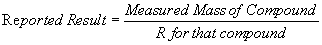
3.3. Optional Correction Step
If the applicable regulation allows for correction of the mass of the compound in the waste by a published fm value, multiply the reported result calculated above with the appropriate fm value for that compound.
[61 FR 34200, July 1, 1996, as amended at 74 FR 30230, June 25, 2009]Appendix E to Part 63 - Monitoring Procedure for Nonthoroughly Mixed Open Biological Treatment Systems at Kraft Pulp Mills Under Unsafe Sampling Conditions
40:16.0.1.1.1.46.325.36.126 : Appendix E
Appendix E to Part 63 - Monitoring Procedure for Nonthoroughly Mixed Open Biological Treatment Systems at Kraft Pulp Mills Under Unsafe Sampling Conditions I. PurposeThis procedure is required to be performed in subpart S of this part, entitled National Emission Standards for Hazardous Air Pollutants from the Pulp and Paper Industry. Subpart S requires this procedure in § 63.453(p)(3) to be followed during unsafe sampling conditions when it is not practicable to obtain representative samples of hazardous air pollutants (HAP) concentrations from an open biological treatment unit. It is assumed that inlet and outlet HAP concentrations from the open biological treatment unit may be obtained during the unsafe sampling conditions. The purpose of this procedure is to estimate the concentration of HAP within the open biological treatment unit based on information obtained at inlet and outlet sampling locations in units that are not thoroughly mixed and, therefore, have different concentrations of HAP at different locations within the unit.
II. DefinitionsBiological treatment unit = wastewater treatment unit designed and operated to promote the growth of bacteria to destroy organic materials in wastewater.
fbio = The fraction of organic compounds in the wastewater biodegraded in a biological treatment unit. Fe = The fraction of applicable organic compounds emitted from the wastewater to the atmosphere. K1 = First-order biodegradation rate constant, L/g mixed liquor volatile suspended solids (MLVSS)-hr KL = Liquid-phase mass transfer coefficient, m/s Ks = Monod biorate constant at half the maximum rate, g/m 3 III. Test Procedure for Determination of fbio for Nonthoroughly Mixed Open Biological Treatment Units Under Unsafe Sampling ConditionsThis test procedure is used under unsafe sampling conditions that do not permit practicable sampling of open biological treatment units within the unit itself, but rather relies on sampling at the inlet and outlet locations of the unit. This procedure may be used only under unsafe sampling conditions to estimate fbio. Once the unsafe conditions have passed, then the formal compliance demonstration procedures of fbio based upon measurements within the open biological treatment unit must be completed.
A. Overview of Estimation ProcedureThe steps in the estimation procedure include data collection, the estimation of concentrations within the unit, and the use of Form 1 to estimate fbio. The data collection procedure consists of two separate components. The first data collection component demonstrates that the open biological treatment unit can be represented by Monod kinetics and characterizes the effectiveness of the open biological treatment unit as part of the initial performance test, and the second data collection component is used when there are unsafe sampling conditions. These two data collection components are used together in a data calculation procedure based on a Monod kinetic model to estimate the concentrations in each zone of the open biological treatment unit. After the first two components of data collection are completed, the calculation procedures are used to back estimate the zone concentrations, starting with the last zone in the series and ending with the first zone.
B. Data Collection RequirementsThis method is based upon modeling the nonthoroughly mixed open biological treatment unit as a series of well-mixed zones with internal recycling between the units and assuming that two Monod biological kinetic parameters can be used to characterize the biological removal rates in each unit. The data collection procedure consists of two separate components. The first data collection component is part of the initial performance test, and the second data collection component is used during unsafe sampling conditions.
1. Initial Performance TestThe objective of the first data collection component is to demonstrate that the open biological treatment unit can be represented by Monod kinetics and to characterize the performance of the open biological treatment unit. An appropriate value of the biorate constant, Ks, is determined using actual sampling data from the open biological treatment unit. This is done during the initial performance test when the open biological treatment unit is operating under normal conditions. This specific Ks value obtained during the initial performance test is used in the calculation procedure to characterize the open biological treatment unit during unsafe sampling conditions. The following open biological treatment unit characterization information is obtained from the first component of the data collection procedure:
(1) The value of the biorate constant, Ks;
(2) The number and characteristics of each zone in the open biological treatment unit (depth, area, characterization parameters for surface aeration, submerged aeration rates, biomass concentration, concentrations of organic compounds, dissolved oxygen (DO), dissolved solids, temperature, and other relevant variables); and
(3) The recycle ratio of internal recirculation between the zones. The number of zones and the above characterization of the zones are also used to determine the performance of the unit under the unsafe sampling conditions of concern.
2. Data Collected Under Unsafe Sampling ConditionsIn the second data collection component obtained under unsafe sampling conditions, the measured inlet and outlet HAP concentrations and the biomass concentration are obtained for the open biological treatment unit. After the site specific data collection is completed on the day a parameter excursion occurs, the inlet and outlet concentrations are used with the prior open biological treatment unit characterization to estimate the concentrations of HAP in each zone. The following information on the open biological treatment unit must be available in the second data collection component:
(1) Basic unit variables such as inlet and recycle wastewater flow rates, type of agitation, and operating conditions;
(2) The value of the inlet and outlet HAP concentrations; and
(3) The biomass concentration in the open biological treatment unit.
C. One Time Determination of a Single Value of Ks (Initial Performance Test)A single value of Ks is calculated using Form 3 for each data set that is collected during the initial performance test. A single composite value of Ks, deemed to be representative of the biological unit, is subsequently selected so that the fbio values calculated by the procedures in this appendix (using this single value of Ks) for the data sets collected during the initial performance test are within 10 percent of the fbio value determined by using Form 1 with these same data sets. The value of Ks meeting these criteria is obtained by the following steps:
(1) Determine the median of the Ks values calculated for each data set;
(2) Estimate fbio for each data set using the selected Ks value (Form 1 and Form 2);
(3) Calculate fbio for each data set using Form 1; and
(4) Compare the fbio values obtained in steps (2) and (3); if the fbio value calculated using step (2) differs from that calculated using step (3) by more than 10 percent, adjust Ks (decrease Ks if the fbio value is lower than that calculated by Form 1 and vice versa) and repeat this procedure starting at step (2). If a negative value is obtained for the values of Ks, then this negative kinetic constant may not be used with the Monod model. If a negative value of Ks is obtained, this test procedure cannot be used for evaluating the performance of the open biological treatment unit.
D. Confirmation of Monod Kinetics (Initial Performance Test)(1) Confirmation that the unit can be represented by Monod kinetics is made by identifying the following two items:
(i) The zone methanol concentrations measured during the initial performance test; and
(ii) The zone methanol concentrations estimated by the Multiple Zone Concentrations Calculations Procedure based on inlet and outlet concentrations (Column A of Form 2). For each zone, the concentration in item 1 is compared to the concentration in item 2.
(2) For each zone, the estimated value of item 2 must be:
(i) Within 25 percent of item 1 when item 1 exceeds 8 mg/L; or
(ii) Within 2 mg/L of item 1 when item 1 is 8 mg/L or less.
(3) Successful demonstration that the calculated zone concentrations meet these criteria must be achieved for 80 percent of the performance test data sets.
(4) If negative values are obtained for the values of K1 and Ks, then these negative kinetic constants may not be used with the Monod model, even if the criteria are met. If negative values are obtained, this test procedure cannot be used for evaluating the performance of the open biological treatment unit.
E. Determination of KL for Each Zone (Unsafe Sampling Conditions)(1) A site-specific liquid-phase mass transfer coefficient (KL) must be obtained for each zone during the unsafe sampling conditions. Do not use a default value for KL. The KL value for each zone must be based on the site-specific parameters of the specific unit. The first step in using this procedure is to calculate KL for each zone in the unit using Form 4. Form 4 outlines the procedure to follow for using mass transfer equations to determine KL. Form 4 identifies the appropriate form to use for providing the detailed calculations to support the estimate of the value of KL. Forms 5 and 6 are used to provide individual compound estimates of KL for quiescent and aerated impoundments, respectively. A computer model may be used to perform the calculations. If the WATER8 model or the most recent update to this model is used, then report the computer model input parameters that you used as an attachment to Form 4. In addition, the Bay Area Sewage Toxics Emission (BASTE) model, version 3.0, or equivalent upgrade and the TOXCHEM (Environment Canada's Wastewater Technology Centre and Environmega, Ltd.) model, version 1.10, or equivalent upgrade may also be used to determine KL for the open biological treatment unit with the following stipulations:
(i) The programs must be altered to output a KL value that is based on the site-specific parameters of the unit modeled; and
(ii) The Henry's law value listed in Form 4 must be substituted for the existing Henry's law values in the models.
(2) The Henry's law value listed in Form 4 may be obtained from the following sources:
(i) Values listed by EPA with temperature adjustment if needed;
(ii) Measured values for the system of concern with temperature adjustment; or
(iii) Literature values of Henry's law values for methanol, adjusted for temperature if needed.
(3) Input values used in the model and corresponding output values shall become part of the documentation of the fbio determination. The owner or operator should be aware that these models may not provide equivalent KL values for some types of units. To obtain an equivalent KL value in this situation, the owner or operator shall either use the appropriate procedure on Form 4 or adjust the KL value from the model to the equivalent KL value as described on Form 4.
(4) Report the input parameters that you used in the computer model on Forms 5, 6, and 7 as an attachment to Form 4. If you have submerged air flow in your unit, you must add the value of KL estimated on Form 7 to the value of KL obtained with Forms 5 and 6 before using the value of KL with Form 2.
F. Estimation of Zone Concentrations (Unsafe Sampling Conditions)Form 2 is used to estimate the zone concentrations of HAP based on the inlet and outlet data. The value of Ks entered on the form is that single composite value of Ks discussed in section III.C of this appendix. This value of Ks is calculated during the Initial Performance Test (and subsequently updated, if necessary). A unique value of the biorate K1 is entered on line 5 of Form 2, and the inlet concentration is estimated in Column A of Form 2. The inlet concentration is located in the row of Form 2 corresponding to zone 0. If there are three zones in the system, n-3 equals 0 for the inlet concentration row. These estimated zone concentrations are then used in Form 1 to estimate f bio for the treatment unit.
G. Quality Control/Quality Assurance (QA/QC)A QA/QC plan outlining the procedures used to determine the measured inlet and outlet concentrations during unsafe conditions and how the zone characterization data were obtained during the initial performance test shall be prepared and submitted with the initial performance test report. The plan should include, but may not be limited to:
(1) A description of each of the sampling methods that were used (method, procedures, time, method to avoid losses during sampling and holding, and sampling procedures) including simplified schematic drawings;
(2) A description of how that biomass was sampled from the biotreatment unit, including methods, locations, and times;
(3) A description of what conditions (DO, temperature, etc.) are important, what the target values are in the zones, how the factors were controlled, and how they were monitored. These conditions are primarily used to establish that the conditions of the initial performance test correspond to the conditions of the day in question;
(4) A description of how each analytical measurement was conducted, including preparation of solutions, dilution procedures, sampling procedures, monitoring of conditions, etc;
(5) A description of the analytical instrumentation used, how the instruments were calibrated, and a summary of the accuracy and precision for each instrument;
(6) A description of the test methods used to determine HAP concentrations and other measurements. Section 63.457(c)(3) specifies the test methods that must be used to determine HAP concentrations. During unsafe sampling conditions, you do not have to sample over an extended period of time or obtain more than one sample at each sample point.
(7) A description of how data are captured, recorded, and stored; and
(8) A description of the equations used and their solutions for sampling and analysis, including a reference to any software used for calculations and/or curve-fitting.
IV. Calculation of Individual fbio (Unsafe Sampling Conditions)Use Form 1 with your zone concentration information to estimate the value of f bio under unsafe sampling conditions. Form 1 uses measured concentrations of HAP in the unit inlet and outlet, and Form 1 also uses the estimated concentrations in each zone of the unit obtained from Form 2. This procedure may be used on an open biological treatment unit that has defined zones within the unit. Use Form 1 to determine fbio for each open biological treatment unit as it exists under subpart S of part 63. The first step in using Form 1 is to calculate KL for each zone in the unit using Form 4. Form 7 must also be used if submerged aeration is used. After KL is determined using field data, obtain the concentrations of the HAP in each zone. In this alternative procedure for unsafe sampling conditions, the actual measured concentrations of the HAP in each zone are replaced with the zone concentrations that are estimated with Form 2. After KL and the zone concentrations are determined, Form 1 is used to estimate the overall unit Fe and fbio for methanol.
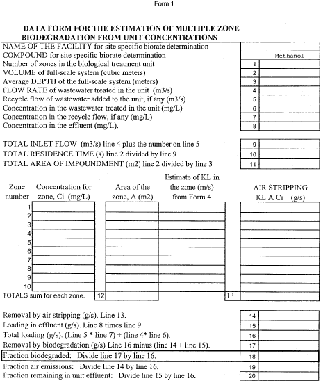
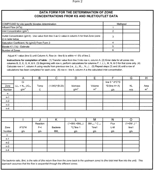
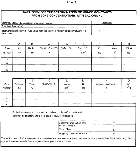
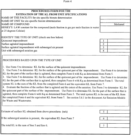
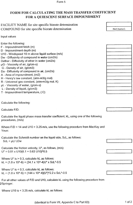
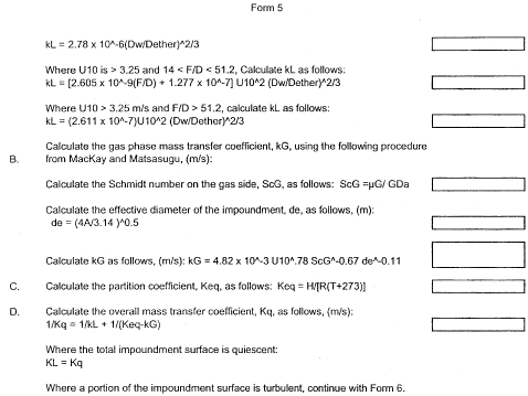
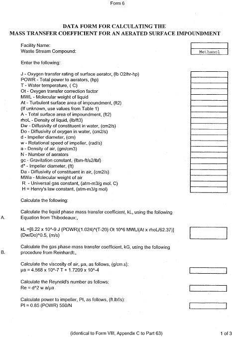
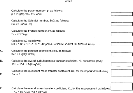
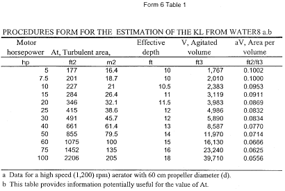
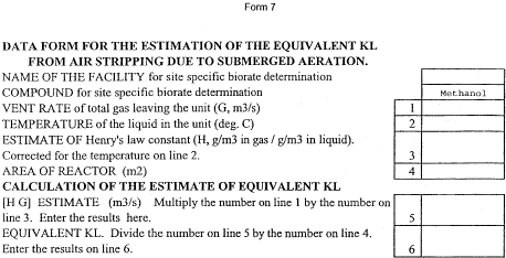 [65 FR 80765, Dec.
22, 2000]
[65 FR 80765, Dec.
22, 2000]