Appendix C to Part 61 - Quality Assurance Procedures
40:10.0.1.1.1.29.1.21.6 : Appendix C
Appendix C to Part 61 - Quality Assurance Procedures Procedure 1 -
Determination of Adequate Chromatographic Peak Resolution
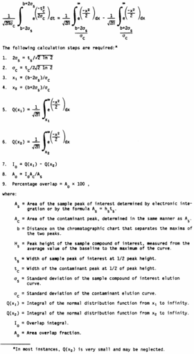
In this method of dealing with resolution, the extent to which
one chromatographic peak overlaps another is determined.
For convenience, consider the range of the elution curve of each
compound as running from −2σ to + 2σ. This range is used in other
resolution criteria, and it contains 95.45 percent of the area of a
normal curve. If two peaks are separated by a known distance, b,
one can determine the fraction of the area of one curve that lies
within the range of the other. The extent to which the elution
curve of a contaminant compound overlaps the curve of a compound
that is under analysis is found by integrating the contaminant
curve over the limits b−2σs to b + 2σs, where σs is the standard
deviation of the sample curve.
This calculation can be simplified in several ways. Overlap can
be determined for curves of unit area; then actual areas can be
introduced. Desired integration can be resolved into two integrals
of the normal distribution function for which there are convenient
calculation programs and tables. An example would be Program 15 in
Texas Instruments Program Manual ST1, 1975, Texas Instruments,
Inc., Dallas, Texas 75222.

In judging the suitability of alternate GC columns or the
effects of altering chromatographic conditions, one can employ the
area overlap as the resolution parameter with a specific maximum
permissible value.
The use of Gaussian functions to describe chromatographic
elution curves is widespread. However, some elution curves are
highly asymmetric. In cases where the sample peak is followed by a
contaminant that has a leading edge that rises sharply but the
curve then tails off, it may be possible to define an effective
width for tc as “twice the distance from the leading edge to a
perpendicular line through the maxim of the contaminant curve,
measured along a perpendicular bisection of that line.”
Procedure 2 - Procedure for Field Auditing GC Analysis
Responsibilities of audit supervisor and analyst at the source
sampling site include the following:
A. The audit supervisor verifies that audit cylinders are stored
in a safe location both before and after the audit to prevent
vandalism.
B. At the beginning and conclusion of the audit, the analyst
records each cylinder number and pressure. An audit cylinder is
never analyzed when the pressure drops below 200 psi.
C. During the audit, the analyst performs a minimum of two
consecutive analyses of each audit cylinder gas. The audit must be
conducted to coincide with the analysis of source test samples,
normally immediately after GC calibration and prior to sample
analyses.
D. At the end of audit analyses, the audit supervisor requests
the calculated concentrations from the analyst and compares the
results with the actual audit concentrations. If each measured
concentration agrees with the respective actual concentration
within ±10 percent, he directs the analyst to begin analyzing
source samples. Audit supervisor judgment and/or supervisory policy
determine action when agreement is not within ±10 percent. When a
consistent bias in excess of 10 percent is found, it may be
possible to proceed with the sample analysis, with a corrective
factor to be applied to the results at a later time. However, every
attempt should be made to locate the cause of the discrepancy, as
it may be misleading. The audit supervisor records each cylinder
number, cylinder pressure (at the end of the audit), and all
calculated concentrations. The individual being audited must not
under any circumstance be told actual audit concentrations until
calculated concentrations have been submitted to the audit
supervisor.
Field Audit Report
Part A - To be filled out by organization supplying audit
cylinders.
1. Organization supplying audit sample(s) and shipping
address
2. Audit supervisor, organization, and phone number
3. Shipping instructions: Name, Address, Attention
4. Guaranteed arrival date for cylinders 5. Planned shipping date
for cylinders
6. Details on audit cylinders from last analysis
|
Low conc. |
High conc. |
| a. Date of last
analysis |
|
|
| b. Cylinder
number |
|
|
| c. Cylinder
pressure, psi |
|
|
| d. Audit
gas(es)/balance gas |
|
|
| e. Audit gas(es),
ppm |
|
|
| f. Cylinder
construction |
|
|
Part B - To be filled out by audit supervisor.
1. Process sampled 2. Audit location 3. Name of individual audit 4.
Audit date
5. Audit results:
|
Low conc. cylinder |
High conc. cylinder |
| a. Cylinder
number |
|
|
| b. Cylinder
pressure before audit, psi |
|
|
| c. Cylinder
pressure after audit, psi |
|
|
| d. Measured
concentration, ppm Injection #1* Injection #2* Average |
|
|
| e. Actual audit
concentration, ppm (Part A, 6e) |
|
|
| f. Audit accuracy:
1 |
|
|
| Low Conc.
Cylinder |
|
|
| High Conc.
Cylinder |
|
|
| Percent
1 accuracy= |
|
|
| Measured Conc. −
Actual Conc. |
|
|
| ________________ ×
100 |
|
|
| Actual Conc. |
|
|
| g. Problems
detected (if any) |
|
|
[47 FR 39178, Sept. 7, 1982]
