Appendix C to Part 50 - Measurement Principle and Calibration Procedure for the Measurement of Carbon Monoxide in the Atmosphere (Non-Dispersive Infrared Photometry)
40:2.0.1.1.1.0.1.20.4 : Appendix C
Appendix C to Part 50 - Measurement Principle and Calibration
Procedure for the Measurement of Carbon Monoxide in the Atmosphere
(Non-Dispersive Infrared Photometry) 1.0 Applicability
1.1 This non-dispersive infrared photometry (NDIR) Federal
Reference Method (FRM) provides measurements of the concentration
of carbon monoxide (CO) in ambient air for determining compliance
with the primary and secondary National Ambient Air Quality
Standards (NAAQS) for CO as specified in § 50.8 of this chapter.
The method is applicable to continuous sampling and measurement of
ambient CO concentrations suitable for determining 1-hour or longer
average measurements. The method may also provide measurements of
shorter averaging times, subject to specific analyzer performance
limitations. Additional CO monitoring quality assurance procedures
and guidance are provided in part 58, appendix A, of this chapter
and in reference 1 of this appendix C.
2.0 Measurement Principle
2.1 Measurements of CO in ambient air are based on automated
measurement of the absorption of infrared radiation by CO in an
ambient air sample drawn into an analyzer employing
non-wavelength-dispersive, infrared photometry (NDIR method).
Infrared energy from a source in the photometer is passed through a
cell containing the air sample to be analyzed, and the quantitative
absorption of energy by CO in the sample cell is measured by a
suitable detector. The photometer is sensitized specifically to CO
by employing CO gas in a filter cell in the optical path, which,
when compared to a differential optical path without a CO filter
cell, limits the measured absorption to one or more of the
characteristic wavelengths at which CO strongly absorbs. However,
to meet measurement performance requirements, various optical
filters, reference cells, rotating gas filter cells, dual-beam
configurations, moisture traps, or other means may also be used to
further enhance sensitivity and stability of the photometer and to
minimize potential measurement interference from water vapor,
carbon dioxide (CO2), or other species. Also, various schemes may
be used to provide a suitable zero reference for the photometer,
and optional automatic compensation may be provided for the actual
pressure and temperature of the air sample in the measurement cell.
The measured infrared absorption, converted to a digital reading or
an electrical output signal, indicates the measured CO
concentration.
2.2 The measurement system is calibrated by referencing the
analyzer's CO measurements to CO concentration standards traceable
to a National Institute of Standards and Technology (NIST) primary
standard for CO, as described in the associated calibration
procedure specified in section 4 of this reference method.
2.3 An analyzer implementing this measurement principle will be
considered a reference method only if it has been designated as a
reference method in accordance with part 53 of this chapter.
2.4 Sampling considerations. The use of a particle filter
in the sample inlet line of a CO FRM analyzer is optional and left
to the discretion of the user unless such a filter is specified or
recommended by the analyzer manufacturer in the analyzer's
associated operation or instruction manual.
3.0 Interferences
3.1 The NDIR measurement principle is potentially susceptible to
interference from water vapor and CO2, which have some infrared
absorption at wavelengths in common with CO and normally exist in
the atmosphere. Various instrumental techniques can be used to
effectively minimize these interferences.
4.0 Calibration Procedures
4.1 Principle. Either of two methods may be selected for
dynamic multipoint calibration of FRM CO analyzers, using test
gases of accurately known CO concentrations obtained from one or
more compressed gas cylinders certified as CO transfer
standards:
4.1.1 Dilution method: A single certified standard
cylinder of CO is quantitatively diluted as necessary with zero air
to obtain the various calibration concentration standards
needed.
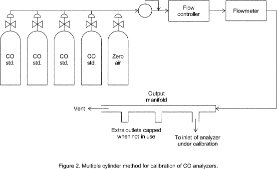
4.1.2 Multiple-cylinder method: Multiple, individually
certified standard cylinders of CO are used for each of the various
calibration concentration standards needed.
4.1.3 Additional information on calibration may be found in
Section 12 of reference 1.
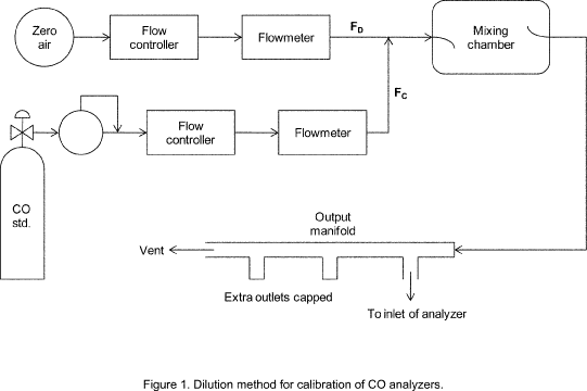
4.2 Apparatus. The major components and typical configurations
of the calibration systems for the two calibration methods are
shown in Figures 1 and 2. Either system may be made up using common
laboratory components, or it may be a commercially manufactured
system. In either case, the principal components are as
follows:
4.2.1 CO standard gas flow control and measurement devices (or a
combined device) capable of regulating and maintaining the standard
gas flow rate constant to within ±2 percent and measuring the gas
flow rate accurate to within ±2 percent, properly calibrated to a
NIST-traceable standard.
4.2.2 For the dilution method (Figure 1), dilution air flow
control and measurement devices (or a combined device) capable of
regulating and maintaining the air flow rate constant to within ±2
percent and measuring the air flow rate accurate to within ±2
percent, properly calibrated to a NIST-traceable standard.
4.2.3 Standard gas pressure regulator(s) for the standard CO
cylinder(s), suitable for use with a high-pressure CO gas cylinder
and having a non-reactive diaphragm and internal parts and a
suitable delivery pressure.
4.2.4 Mixing chamber for the dilution method of an inert
material and of proper design to provide thorough mixing of CO
standard gas and diluent air streams.
4.2.5 Output sampling manifold, constructed of an inert material
and of sufficient diameter to ensure an insignificant pressure drop
at the analyzer connection. The system must have a vent designed to
ensure nearly atmospheric pressure at the analyzer connection port
and to prevent ambient air from entering the manifold.
4.3 Reagents
4.3.1 CO gas concentration transfer standard(s) of CO in air,
containing an appropriate concentration of CO suitable for the
selected operating range of the analyzer under calibration and
traceable to a NIST standard reference material (SRM). If the CO
analyzer has significant sensitivity to CO2, the CO standard(s)
should also contain 350 to 400 ppm CO2 to replicate the typical CO2
concentration in ambient air. However, if the zero air dilution
ratio used for the dilution method is not less than 100:1 and the
zero air contains ambient levels of CO2, then the CO standard may
be contained in nitrogen and need not contain CO2.
4.3.2 For the dilution method, clean zero air, free of
contaminants that could cause a detectable response on or a change
in sensitivity of the CO analyzer. The zero air should contain
<0.1 ppm CO.
4.4 Procedure Using the Dilution Method
4.4.1 Assemble or obtain a suitable dynamic dilution calibration
system such as the one shown schematically in Figure 1. Generally,
all calibration gases including zero air must be introduced into
the sample inlet of the analyzer. However, if the analyzer has
special, approved zero and span inlets and automatic valves to
specifically allow introduction of calibration standards at near
atmospheric pressure, such inlets may be used for calibration in
lieu of the sample inlet. For specific operating instructions,
refer to the manufacturer's manual.
4.4.2 Ensure that there are no leaks in the calibration system
and that all flowmeters are properly and accurately calibrated,
under the conditions of use, if appropriate, against a reliable
volume or flow rate standard such as a soap-bubble meter or
wet-test meter traceable to a NIST standard. All volumetric flow
rates should be corrected to the same temperature and pressure such
as 298.15 K (25 °C) and 760 mm Hg (101 kPa), using a correction
formula such as the following:

Where:
Fc = corrected flow rate (L/min at 25 °C and 760 mm Hg),
Fm = measured flow rate (at temperature
Tm and
pressure
Pm),
Pm = measured pressure in mm Hg
(absolute), and
Tm = measured temperature in degrees
Celsius.
4.4.3 Select the operating range of the CO analyzer to be
calibrated. Connect the measurement signal output of the analyzer
to an appropriate readout instrument to allow the analyzer's
measurement output to be continuously monitored during the
calibration. Where possible, this readout instrument should be the
same one used to record routine monitoring data, or, at least, an
instrument that is as closely representative of that system as
feasible.
4.4.4 Connect the inlet of the CO analyzer to the
output-sampling manifold of the calibration system.
4.4.5 Adjust the calibration system to deliver zero air to the
output manifold. The total air flow must exceed the total demand of
the analyzer(s) connected to the output manifold to ensure that no
ambient air is pulled into the manifold vent. Allow the analyzer to
sample zero air until a stable response is obtained. After the
response has stabilized, adjust the analyzer zero reading.
4.4.6 Adjust the zero air flow rate and the CO gas flow rate
from the standard CO cylinder to provide a diluted CO concentration
of approximately 80 percent of the measurement upper range limit
(URL) of the operating range of the analyzer. The total air flow
rate must exceed the total demand of the analyzer(s) connected to
the output manifold to ensure that no ambient air is pulled into
the manifold vent. The exact CO concentration is calculated
from:

Where:
[
CO]OUT = diluted CO concentration at the output manifold
(ppm), [
CO]STD = concentration of the undiluted CO standard
(ppm),
FCO = flow rate of the CO standard (L/min), and
FD = flow rate of the dilution air (L/min). Sample this CO
concentration until a stable response is obtained. Adjust the
analyzer span control to obtain the desired analyzer response
reading equivalent to the calculated standard concentration. If
substantial adjustment of the analyzer span control is required, it
may be necessary to recheck the zero and span adjustments by
repeating steps 4.4.5 and 4.4.6. Record the CO concentration and
the analyzer's final response.
4.4.7 Generate several additional concentrations (at least three
evenly spaced points across the remaining scale are suggested to
verify linearity) by decreasing FCO or increasing FD.
Be sure the total flow exceeds the analyzer's total flow demand.
For each concentration generated, calculate the exact CO
concentration using equation (2). Record the concentration and the
analyzer's stable response for each concentration. Plot the
analyzer responses (vertical or y-axis) versus the corresponding CO
concentrations (horizontal or x-axis). Calculate the linear
regression slope and intercept of the calibration curve and verify
that no point deviates from this line by more than 2 percent of the
highest concentration tested.
4.5 Procedure Using the Multiple-Cylinder Method. Use the
procedure for the dilution method with the following changes:
4.5.1 Use a multi-cylinder, dynamic calibration system such as
the typical one shown in Figure 2.
4.5.2 The flowmeter need not be accurately calibrated, provided
the flow in the output manifold can be verified to exceed the
analyzer's flow demand.
4.5.3 The various CO calibration concentrations required in
Steps 4.4.5, 4.4.6, and 4.4.7 are obtained without dilution by
selecting zero air or the appropriate certified standard
cylinder.
4.6 Frequency of Calibration. The frequency of
calibration, as well as the number of points necessary to establish
the calibration curve and the frequency of other performance
checking, will vary by analyzer. However, the minimum frequency,
acceptance criteria, and subsequent actions are specified in
reference 1, appendix D, “Measurement Quality Objectives and
Validation Template for CO” (page 5 of 30). The user's quality
control program should provide guidelines for initial establishment
of these variables and for subsequent alteration as operational
experience is accumulated. Manufacturers of CO analyzers should
include in their instruction/operation manuals information and
guidance as to these variables and on other matters of operation,
calibration, routine maintenance, and quality control.
5.0 Reference
1. QA Handbook for Air Pollution Measurement Systems - Volume
II. Ambient Air Quality Monitoring Program. U.S. EPA.
EPA-454/B-08-003 (2008).


[76 FR 54323, Aug.
31, 2011]