(Non-mandatory) Appendix D to Subpart L of Part 1926 - List of Training Topics for Scaffold Erectors and Dismantlers
29:8.1.1.1.1.12.19.6.4 : Appendix D
(Non-mandatory) Appendix D to Subpart L of Part 1926 - List of
Training Topics for Scaffold Erectors and Dismantlers
This appendix D is provided to serve as a guide to assist
employers when evaluating the training needs of employees erecting
or dismantling supported scaffolds.
The Agency believes that employees erecting or dismantling
scaffolds should be trained in the following topics:
•
General Overview of Scaffolding • regulations and
standards • erection/dismantling planning • PPE and proper
procedures • fall protection • materials handling • access •
working platforms • foundations • guys, ties and braces •
Tubular Welded Frame Scaffolds • specific regulations and
standards • components • parts inspection • erection/dismantling
planning • guys, ties and braces • fall protection • general safety
• access and platforms • erection/dismantling procedures • rolling
scaffold assembly • putlogs •
Tube and Clamp Scaffolds •
specific regulations and standards • components • parts inspection
• erection/dismantling planning • guys, ties and braces • fall
protection • general safety • access and platforms •
erection/dismantling procedures • buttresses, cantilevers, &
bridges •
System Scaffolds • specific regulations and
standards • components • parts inspection • erection/dismantling
planning • guys, ties and braces • fall protection • general safety
• access and platforms • erection/dismantling procedures •
buttresses, cantilevers, & bridges
Scaffold erectors and dismantlers should all receive the general
overview, and, in addition, specific training for the type of
supported scaffold being erected or dismantled.
Appendix D to Subpart M of Part 1926 - Positioning Device Systems
29:8.1.1.1.1.13.19.5.9 : Appendix D
Appendix D to Subpart M of Part 1926 - Positioning Device Systems
Non-Mandatory Guidelines for Complying With § 1926.502(e)
I. Testing Methods For Positioning Device Systems. This
appendix serves as a non-mandatory guideline to assist employers
comply with the requirements for positioning device systems in §
1926.502(e). Paragraphs (b), (c), (d) and (e) of appendix C of
subpart M relating to § 1926.502(d) - Personal Fall Arrest Systems
- set forth test procedures which may be used, along with the
procedures listed below, to determine compliance with the
requirements for positioning device systems in § 1926.502(e) (3)
and (4) of subpart M.
(a) General. (1) Single strap positioning devices shall
have one end attached to a fixed anchorage and the other end
connected to a body belt or harness in the same manner as they
would be used to protect employees. Double strap positioning
devices, similar to window cleaner's belts, shall have one end of
the strap attached to a fixed anchorage and the other end shall
hang free. The body belt or harness shall be attached to the strap
in the same manner as it would be used to protect employees. The
two strap ends shall be adjusted to their maximum span.
(2) The fixed anchorage shall be rigid, and shall not have a
deflection greater than .04 inches (1 mm) when a force of 2,250
pounds (10 kN) is applied.
(3) During the testing of all systems, a test weight of 250
pounds plus or minus 3 pounds (113 kg plus or minus 1.6 kg) shall
be used. The weight shall be a rigid object with a girth of 38
inches plus or minus 4 inches (96 cm plus or minus 10 cm).
(4) Each test shall consist of dropping the specified weight one
time without failure of the system being tested. A new system shall
be used for each test.
(5) The test weight for each test shall be hoisted exactly 4
feet (1.2 m above its “at rest” position), and shall be dropped so
as to permit a vertical free fall of 4 feet (1.2 m).
(6) The test is failed whenever any breakage or slippage occurs
which permits the weight to fall free of the system.
(7) Following the test, the system need not be capable of
further operation; however, all such incapacities shall be readily
apparent.
II. Inspection Considerations. As required in § 1926.502
(e)(5), positioning device systems must be regularly inspected. Any
component with any significant defect, such as cuts, tears,
abrasions, mold, or undue stretching; alterations or additions
which might affect its efficiency; damage due to deterioration;
contact with fire, acids, or other corrosives; distorted hooks or
faulty hook springs; tongues unfitted to the shoulder of buckles;
loose or damaged mountings; non-functioning parts; or wearing or
internal deterioration in the ropes must be withdrawn from service
immediately, and should be tagged or marked as unusable, or
destroyed.
Appendix D to Subpart P of Part 1926 - Aluminum Hydraulic Shoring for Trenches
29:8.1.1.1.1.16.19.4.14 : Appendix D
Appendix D to Subpart P of Part 1926 - Aluminum Hydraulic Shoring
for Trenches
(a) Scope. This appendix contains information that can be
used when aluminum hydraulic shoring is provided as a method of
protection against cave-ins in trenches that do not exceed 20 feet
(6.1m) in depth. This appendix must be used when design of the
aluminum hydraulic protective system cannot be performed in
accordance with § 1926.652(c)(2).
(b) Soil Classification. In order to use data presented
in this appendix, the soi1 type or types in which the excavation is
made must first be determined using the soil classification method
set forth in appendix A of subpart P of part 1926.
(c) Presentation of Information. Information is presented
in several forms as follows:
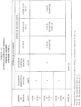
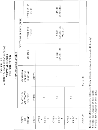
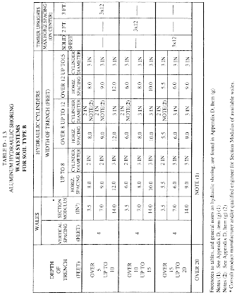
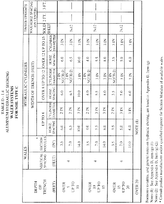
(1) Information is presented in tabular form in Tables D-1.1,
D-1.2, D-1.3 and E-1.4. Each table presents the maximum vertical
and horizontal spacings that may be used with various aluminum
member sizes and various hydraulic cylinder sizes. Each table
contains data only for the particular soil type in which the
excavation or portion of the excavation is made. Tables D-1.1 and
D-1.2 are for vertical shores in Types A and B soil. Tables D-1.3
and D1.4 are for horizontal waler systems in Types B and C
soil.
(2) Information concerning the basis of the tabular data and the
limitations of the data is presented in paragraph (d) of this
appendix.
(3) Information explaining the use of the tabular data is
presented in paragraph (e) of this appendix.
(4) Information illustrating the use of the tabular data is
presented in paragraph (f) of this appendix.
(5) Miscellaneous notations (footnotes) regarding Table D-1.1
through D-1.4 are presented in paragraph (g) of this appendix.
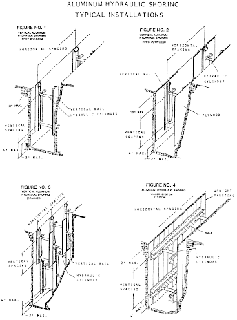
(6) Figures, illustrating typical installations of hydraulic
shoring, are included just prior to the Tables. The illustrations
page is entitled “Aluminum Hydraulic Shoring; Typical
Installations.”
(d) Basis and limitations of the data. (1) Vertical shore
rails and horizontal wales are those that meet the Section Modulus
requirements in the D-1 Tables. Aluminum material is 6061-T6 or
material of equivalent strength and properties.
(2) Hydraulic cylinders specifications. (i) 2-inch cylinders
shall be a minimum 2-inch inside diameter with a minimum safe
working capacity of no less than 18,000 pounds axial compressive
load at maximum extension. Maximum extension is to include full
range of cylinder extensions as recommended by product
manufaturer.
(ii) 3-inch cylinders shall be a minimum 3-inch inside diameter
with a safe working capacity of not less than 30,000 pounds axial
compressive load at extensions as recommended by product
manufacturer.
(3) Limitation of application.
(i) It is not intended that the aluminum hydraulic specification
apply to every situation that may be experienced in the field.
These data were developed to apply to the situations that are most
commonly experienced in current trenching practice. Shoring systems
for use in situations that are not covered by the data in this
appendix must be otherwise designed as specified in §
1926.652(c).
(ii) When any of the following conditions are present, the
members specified in the Tables are not considered adequate. In
this case, an alternative aluminum hydraulic shoring system or
other type of protective system must be designed in accordance with
§ 1926.652.
(A) When vertical loads imposed on cross braces exceed a 100
Pound gravity load distributed on a one foot section of the center
of the hydraulic cylinder.
(B) When surcharge loads are present from equipment weighing in
excess of 20,000 pounds.
(C) When only the lower portion or a trench is shored and the
remaining portion of the trench is sloped or benched unless: The
sloped portion is sloped at an angle less steep than three
horizontal to one vertical; or the members are selected from the
tables for use at a depth which is determined from the top of the
overall trench, and not from the toe of the sloped portion.
(e) Use of Tables D-1.1, D-1.2, D-1.3 and D-1.4. The
members of the shoring system that are to be selected using this
information are the hydraulic cylinders, and either the vertical
shores or the horizontal wales. When a waler system is used the
vertical timber sheeting to be used is also selected from these
tables. The Tables D-1.1 and D-1.2 for vertical shores are used in
Type A and B soils that do not require sheeting. Type B soils that
may require sheeting, and Type C soils that always require sheeting
are found in the horizontal wale Tables D-1.3 and D-1.4. The soil
type must first be determined in accordance with the soil
classification system described in appendix A to subpart P of part
1926. Using the appropriate table, the selection of the size and
spacing of the members is made. The selection is based on the depth
and width of the trench where the members are to be installed. In
these tables the vertical spacing is held constant at four feet on
center. The tables show the maximum horizontal spacing of cylinders
allowed for each size of wale in the waler system tables, and in
the vertical shore tables, the hydraulic cylinder horizontal
spacing is the same as the vertical shore spacing.
(f) Example to Illustrate the Use of the Tables:
(1) Example 1:
A trench dug in Type A soil is 6 feet deep and 3 feet wide. From
Table D-1.1: Find vertical shores and 2 inch diameter cylinders
spaced 8 feet on center (o.c.) horizontally and 4 feet on center
(o.c.) vertically. (See Figures 1 & 3 for typical
installations.)
(2) Example 2:
A trench is dug in Type B soil that does not require sheeting,
13 feet deep and 5 feet wide. From Table D-1.2: Find vertical
shores and 2 inch diameter cylinders spaced 6.5 feet o.c.
horizontally and 4 feet o.c. vertically. (See Figures 1 & 3 for
typical installations.)
(3) A trench is dug in Type B soil that does not require
sheeting, but does experience some minor raveling of the trench
face. The trench is 16 feet deep and 9 feet wide. From Table D-1.2:
Find vertical shores and 2 inch diameter cylinder (with special
oversleeves as designated by footnote #B2) spaced 5.5 feet o.c.
horizontally and 4 feet o.c. vertically, plywood (per footnote
(g)(7) to the D-1 Table) should be used behind the shores. (See
Figures 2 & 3 for typical installations.)
(4) Example 4: A trench is dug in previously disturbed Type B
soil, with characteristics of a Type C soil, and will require
sheeting. The trench is 18 feet deep and 12 feet wide. 8 foot
horizontal spacing between cylinders is desired for working space.
From Table D-1.3: Find horizontal wale with a section modulus of
14.0 spaced at 4 feet o.c. vertically and 3 inch diameter cylinder
spaced at 9 feet maximum o.c. horizontally. 3 × 12 timber sheeting
is required at close spacing vertically. (See Figure 4 for typical
installation.)
(5) Example 5: A trench is dug in Type C soil, 9 feet deep and 4
feet wide. Horizontal cylinder spacing in excess of 6 feet is
desired for working space. From Table D-1.4: Find horizontal wale
with a section modulus of 7.0 and 2 inch diameter cylinders spaced
at 6.5 feet o.c. horizontally. Or, find horizontal wale with a 14.0
section modulus and 3 inch diameter cylinder spaced at 10 feet o.c.
horizontally. Both wales are spaced 4 feet o.c. vertically. 3 × 12
timber sheeting is required at close spacing vertically. (See
Figure 4 for typical installation.)
(g) Footnotes, and general notes, for Tables D-1.1, D-1.2,
D-1.3, and D-1.4.
(1) For applications other than those listed in the tables,
refer to § 1926.652(c)(2) for use of manufacturer's tabulated data.
For trench depths in excess of 20 feet, refer to § 1926.652(c)(2)
and § 1926.652(c)(3).
(2) 2 inch diameter cylinders, at this width, shall have
structural steel tube (3.5 × 3.5 × 0.1875) oversleeves, or
structural oversleeves of manufacturer's specification, extending
the full, collapsed length.
(3) Hydraulic cylinders capacities. (i) 2 inch cylinders shall
be a minimum 2-inch inside diameter with a safe working capacity of
not less than 18,000 pounds axial compressive load at maximum
extension. Maximum extension is to include full range of cylinder
extensions as recommended by product manufacturer.
(ii) 3-inch cylinders shall be a minimum 3-inch inside diameter
with a safe work capacity of not less than 30,000 pounds axial
compressive load at maximum extension. Maximum extension is to
include full range of cylinder extensions as recommended by product
manufacturer.
(4) All spacing indicated is measured center to center.
(5) Vertical shoring rails shall have a minimum section modulus
of 0.40 inch.
(6) When vertical shores are used, there must be a minimum of
three shores spaced equally, horizontally, in a group.
(7) Plywood shall be 1.125 in. thick softwood or 0.75 inch.
thick, 14 ply, arctic white birch (Finland form). Please note that
plywood is not intended as a structural member, but only for
prevention of local raveling (sloughing of the trench face) between
shores.
(8) See appendix C for timber specifications.
(9) Wales are calculated for simple span conditions.
(10) See appendix D, item (d), for basis and limitations of the
data.
Appendix D to Subpart R of Part 1926 - Illustration of the Use of Control Lines To Demarcate Controlled Decking Zones (CDZs): Non-mandatory Guidelines for Complying With § 1926.760(c)(3)
29:8.1.1.1.1.18.19.13.21 : Appendix D
Appendix D to Subpart R of Part 1926 - Illustration of the Use of
Control Lines To Demarcate Controlled Decking Zones (CDZs):
Non-mandatory Guidelines for Complying With § 1926.760(c)(3)
(1) When used to control access to areas where leading edge and
initial securement of metal deck and other operations connected
with leading edge work are taking place, the controlled decking
zone (CDZ) is defined by a control line or by any other means that
restricts access.
(i) A control line for a CDZ is erected not less than 6 feet
(1.8 m) nor more than 90 feet (27.4 m) from the leading edge.
(ii) Control lines extend along the entire length of the
unprotected or leading edge and are approximately parallel to the
unprotected or leading edge.
(iii) Control lines are connected on each side to a guardrail
system, wall, stanchion or other suitable anchorage.
(2) Control lines consist of ropes, wires, tapes, or equivalent
materials, and supporting stanchions as follows:
(i) Each line is rigged and supported in such a way that its
lowest point (including sag) is not less than 39 inches (1.0 m)
from the walking/working surface and its highest point is not more
than 45 inches (1.3 m) from the walking/working surface.
(ii) Each line has a minimum breaking strength of 200 pounds
(90.8 kg).
Appendix D to Subpart V of Part 1926 - Methods of Inspecting and Testing Wood Poles
29:8.1.1.1.1.22.19.20.30 : Appendix D
Appendix D to Subpart V of Part 1926 - Methods of Inspecting and
Testing Wood Poles I. Introduction
When employees are to perform work on a wood pole, it is
important to determine the condition of the pole before employees
climb it. The weight of the employee, the weight of equipment to be
installed, and other working stresses (such as the removal or
retensioning of conductors) can lead to the failure of a defective
pole or a pole that is not designed to handle the additional
stresses. 1 For these reasons, it is essential that, before an
employee climbs a wood pole, the employer ascertain that the pole
is capable of sustaining the stresses of the work. The
determination that the pole is capable of sustaining these stresses
includes an inspection of the condition of the pole.
1 A properly guyed pole in good condition should, at a minimum,
be able to handle the weight of an employee climbing it.
If the employer finds the pole to be unsafe to climb or to work
from, the employer must secure the pole so that it does not fail
while an employee is on it. The employer can secure the pole by a
line truck boom, by ropes or guys, or by lashing a new pole
alongside it. If a new one is lashed alongside the defective pole,
employees should work from the new one.
II. Inspecting Wood Poles
A qualified employee should inspect wood poles for the following
conditions: 2
2 The presence of any of these conditions is an indication that
the pole may not be safe to climb or to work from. The employee
performing the inspection must be qualified to make a determination
as to whether it is safe to perform the work without taking
additional precautions.
A. General condition. Buckling at the ground line or an
unusual angle with respect to the ground may indicate that the pole
has rotted or is broken.
B. Cracks. Horizontal cracks perpendicular to the grain
of the wood may weaken the pole. Vertical cracks, although not
normally considered to be a sign of a defective pole, can pose a
hazard to the climber, and the employee should keep his or her
gaffs away from them while climbing.
C. Holes. Hollow spots and woodpecker holes can reduce
the strength of a wood pole.
D. Shell rot and decay. Rotting and decay are cutout
hazards and possible indications of the age and internal condition
of the pole.
E. Knots. One large knot or several smaller ones at the
same height on the pole may be evidence of a weak point on the
pole.
F. Depth of setting. Evidence of the existence of a
former ground line substantially above the existing ground level
may be an indication that the pole is no longer buried to a
sufficient depth.
G. Soil conditions. Soft, wet, or loose soil around the
base of the pole may indicate that the pole will not support any
change in stress.
H. Burn marks. Burning from transformer failures or
conductor faults could damage the pole so that it cannot withstand
changes in mechanical stress.
III. Testing Wood Poles
The following tests, which are from § 1910.268(n)(3) of this
chapter, are acceptable methods of testing wood poles:
A. Hammer test. Rap the pole sharply with a hammer
weighing about 1.4 kg (3 pounds), starting near the ground line and
continuing upwards circumferentially around the pole to a height of
approximately 1.8 meters (6 feet). The hammer will produce a clear
sound and rebound sharply when striking sound wood. Decay pockets
will be indicated by a dull sound or a less pronounced hammer
rebound. Also, prod the pole as near the ground line as possible
using a pole prod or a screwdriver with a blade at least 127
millimeters (5 inches) long. If substantial decay is present, the
pole is unsafe.
B. Rocking test. Apply a horizontal force to the pole and
attempt to rock it back and forth in a direction perpendicular to
the line. Exercise caution to avoid causing power lines to swing
together. Apply the force to the pole either by pushing it with a
pike pole or pulling the pole with a rope. If the pole cracks
during the test, it is unsafe.