(Non-mandatory) Appendix C to Subpart L of Part 1926 - List of National Consensus Standards
29:8.1.1.1.1.12.19.6.3 : Appendix C
(Non-mandatory) Appendix C to Subpart L of Part 1926 - List of
National Consensus Standards ANSI/SIA A92.2-1990 Vehicle-Mounted
Elevating and Rotating Aerial Devices ANSI/SIA A92.3-1990
Manually Propelled Elevating Aerial Platforms ANSI/SIA
A92.5-1990 Boom Supported Elevating Work Platforms ANSI/SIA
A92.6-1990 Self-Propelled Elevating Work Platforms ANSI/SIA
A92.7-1990 Airline Ground Support Vehicle-Mounted Vertical Lift
Devices ANSI/SIA A92.8-1993 Vehicle-Mounted Bridge
Inspection and Maintenance Devices ANSI/SIA A92.9-1993
Mast-Climbing Work Platforms
Appendix C to Subpart M of Part 1926 - Personal Fall Arrest Systems
29:8.1.1.1.1.13.19.5.8 : Appendix C
Appendix C to Subpart M of Part 1926 - Personal Fall Arrest Systems
Non-Mandatory Guidelines for Complying With § 1926.502(d)
I. Test methods for personal fall arrest systems and
positioning device systems - (a) General. This appendix
serves as a non-mandatory guideline to assist employers comply with
the requirements in § 1926.502(d). Paragraphs (b), (c), (d) and (e)
of this appendix describe test procedures which may be used to
determine compliance with the requirements in § 1926.502 (d)(16).
As noted in appendix D of this subpart, the test methods listed
here in appendix C can also be used to assist employers comply with
the requirements in § 1926.502(e) (3) and (4) for positioning
device systems.
(b) General conditions for all tests in the appendix to §
1926.502(d). (1) Lifelines, lanyards and deceleration devices
should be attached to an anchorage and connected to the body-belt
or body harness in the same manner as they would be when used to
protect employees.
(2) The anchorage should be rigid, and should not have a
deflection greater than 0.04 inches (1 mm) when a force of 2,250
pounds (10 kN) is applied.
(3) The frequency response of the load measuring instrumentation
should be 500 Hz.
(4) The test weight used in the strength and force tests should
be a rigid, metal, cylindrical or torso-shaped object with a girth
of 38 inches plus or minus 4 inches (96 cm plus or minus 10
cm).
(5) The lanyard or lifeline used to create the free fall
distance should be supplied with the system, or in its absence, the
least elastic lanyard or lifeline available to be used with the
system.
(6) The test weight for each test should be hoisted to the
required level and should be quickly released without having any
appreciable motion imparted to it.
(7) The system's performance should be evaluated taking into
account the range of environmental conditions for which it is
designed to be used.
(8) Following the test, the system need not be capable of
further operation.
(c) Strength test. (1) During the testing of all systems,
a test weight of 300 pounds plus or minus 5 pounds (135 kg plus or
minus 2.5 kg) should be used. (See paragraph (b)(4) of this
section.)
(2) The test consists of dropping the test weight once. A new
unused system should be used for each test.
(3) For lanyard systems, the lanyard length should be 6 feet
plus or minus 2 inches (1.83 m plus or minus 5 cm) as measured from
the fixed anchorage to the attachment on the body belt or body
harness.
(4) For rope-grab-type deceleration systems, the length of the
lifeline above the centerline of the grabbing mechanism to the
lifeline's anchorage point should not exceed 2 feet (0.61 m).
(5) For lanyard systems, for systems with deceleration devices
which do not automatically limit free fall distance to 2 feet (0.61
m) or less, and for systems with deceleration devices which have a
connection distance in excess of 1 foot (0.3 m) (measured between
the centerline of the lifeline and the attachment point to the body
belt or harness), the test weight should be rigged to free fall a
distance of 7.5 feet (2.3 m) from a point that is 1.5 feet (.46 m)
above the anchorage point, to its hanging location (6 feet below
the anchorage). The test weight should fall without interference,
obstruction, or hitting the floor or ground during the test. In
some cases a non-elastic wire lanyard of sufficient length may need
to be added to the system (for test purposes) to create the
necessary free fall distance.
(6) For deceleration device systems with integral lifelines or
lanyards which automatically limit free fall distance to 2 feet
(0.61 m) or less, the test weight should be rigged to free fall a
distance of 4 feet (1.22 m).
(7) Any weight which detaches from the belt or harness has
failed the strength test.
(d) Force test - (1) General. The test consists of
dropping the respective test weight once as specified in paragraph
(d)(2)(i) or (d)(3)(i) of this section. A new, unused system should
be used for each test.
(2) For lanyard systems. (i) A test weight of 220 pounds
plus or minus 3 pounds (100 kg plus or minus 1.6 kg) should be
used. (See paragraph (b)(4) of this appendix).
(ii) Lanyard length should be 6 feet plus or minus two inches
(1.83 m plus or minus 5 cm) as measured from the fixed anchorage to
the attachment on the body belt or body harness.
(iii) The test weight should fall free from the anchorage level
to its hanging location (a total of 6 feet (1.83 m) free fall
distance) without interference, obstruction, or hitting the floor
or ground during the test.
(3) For all other systems. (i) A test weight of 220
pounds plus or minus 3 pounds (100 kg plus or minus 1.6 kg) should
be used. (See paragraph (b)(4) of this appendix)
(ii) The free fall distance to be used in the test should be the
maximum fall distance physically permitted by the system during
normal use conditions, up to a maximum free fall distance for the
test weight of 6 feet (1.83 m), except as follows:
(A) For deceleration systems which have a connection link or
lanyard, the test weight should free fall a distance equal to the
connection distance (measured between the centerline of the
lifeline and the attachment point to the body belt or harness).
(B) For deceleration device systems with integral lifelines or
lanyards which automatically limit free fall distance to 2 feet
(0.61 m) or less, the test weight should free fall a distance equal
to that permitted by the system in normal use. (For example, to
test a system with a self-retracting lifeline or lanyard, the test
weight should be supported and the system allowed to retract the
lifeline or lanyard as it would in normal use. The test weight
would then be released and the force and deceleration distance
measured).
(4) A system fails the force test if the recorded maximum
arresting force exceeds 1,260 pounds (5.6 kN) when using a body
belt, and/or exceeds 2,520 pounds (11.2 kN) when using a body
harness.
(5) The maximum elongation and deceleration distance should be
recorded during the force test.
(e) Deceleration device tests - (1) General. The
device should be evaluated or tested under the environmental
conditions, (such as rain, ice, grease, dirt, type of lifeline,
etc.), for which the device is designed.
(2) Rope-grab-type deceleration devices. (i) Devices
should be moved on a lifeline 1,000 times over the same length of
line a distance of not less than 1 foot (30.5 cm), and the
mechanism should lock each time.
(ii) Unless the device is permanently marked to indicate the
type(s) of lifeline which must be used, several types (different
diameters and different materials), of lifelines should be used to
test the device.
(3) Other self-activating-type deceleration devices. The
locking mechanisms of other self-activating-type deceleration
devices designed for more than one arrest should lock each of 1,000
times as they would in normal service.
II. Additional non-mandatory guidelines for personal fall
arrest systems. The following information constitutes
additional guidelines for use in complying with requirements for a
personal fall arrest system.
(a) Selection and use considerations. (1) The kind of
personal fall arrest system selected should match the particular
work situation, and any possible free fall distance should be kept
to a minimum. Consideration should be given to the particular work
environment. For example, the presence of acids, dirt, moisture,
oil, grease, etc., and their effect on the system, should be
evaluated. Hot or cold environments may also have an adverse effect
on the system. Wire rope should not be used where an electrical
hazard is anticipated. As required by the standard, the employer
must plan to have means available to promptly rescue an employee
should a fall occur, since the suspended employee may not be able
to reach a work level independently.
(2) Where lanyards, connectors, and lifelines are subject to
damage by work operations such as welding, chemical cleaning, and
sandblasting, the component should be protected, or other securing
systems should be used. The employer should fully evaluate the work
conditions and environment (including seasonal weather changes)
before selecting the appropriate personal fall protection system.
Once in use, the system's effectiveness should be monitored. In
some cases, a program for cleaning and maintenance of the system
may be necessary.
(b) Testing considerations. Before purchasing or putting
into use a personal fall arrest system, an employer should obtain
from the supplier information about the system based on its
performance during testing so that the employer can know if the
system meets this standard. Testing should be done using recognized
test methods. This appendix contains test methods recognized for
evaluating the performance of fall arrest systems. Not all systems
may need to be individually tested; the performance of some systems
may be based on data and calculations derived from testing of
similar systems, provided that enough information is available to
demonstrate similarity of function and design.
(c) Component compatibility considerations. Ideally, a
personal fall arrest system is designed, tested, and supplied as a
complete system. However, it is common practice for lanyards,
connectors, lifelines, deceleration devices, body belts and body
harnesses to be interchanged since some components wear out before
others. The employer and employee should realize that not all
components are interchangeable. For instance, a lanyard should not
be connected between a body belt (or harness) and a deceleration
device of the self-retracting type since this can result in
additional free fall for which the system was not designed. Any
substitution or change to a personal fall arrest system should be
fully evaluated or tested by a competent person to determine that
it meets the standard, before the modified system is put in
use.
(d) Employee training considerations. Thorough employee
training in the selection and use of personal fall arrest systems
is imperative. Employees must be trained in the safe use of the
system. This should include the following: application limits;
proper anchoring and tie-off techniques; estimation of free fall
distance, including determination of deceleration distance, and
total fall distance to prevent striking a lower level; methods of
use; and inspection and storage of the system. Careless or improper
use of the equipment can result in serious injury or death.
Employers and employees should become familiar with the material in
this Appendix, as well as manufacturer's recommendations, before a
system is used. Of uppermost importance is the reduction in
strength caused by certain tie-offs (such as using knots, tying
around sharp edges, etc.) and maximum permitted free fall distance.
Also, to be stressed are the importance of inspections prior to
use, the limitations of the equipment, and unique conditions at the
worksite which may be important in determining the type of system
to use.
(e) Instruction considerations. Employers should obtain
comprehensive instructions from the supplier as to the system's
proper use and application, including, where applicable:
(1) The force measured during the sample force test;
(2) The maximum elongation measured for lanyards during the
force test;
(3) The deceleration distance measured for deceleration devices
during the force test;
(4) Caution statements on critical use limitations;
(5) Application limits;
(6) Proper hook-up, anchoring and tie-off techniques, including
the proper dee-ring or other attachment point to use on the body
belt and harness for fall arrest;
(7) Proper climbing techniques;
(8) Methods of inspection, use, cleaning, and storage; and
(9) Specific lifelines which may be used. This information
should be provided to employees during training.
(f) Rescue considerations. As required by §
1926.502(d)(20), when personal fall arrest systems are used, the
employer must assure that employees can be promptly rescued or can
rescue themselves should a fall occur. The availability of rescue
personnel, ladders or other rescue equipment should be evaluated.
In some situations, equipment which allows employees to rescue
themselves after the fall has been arrested may be desirable, such
as devices which have descent capability.
(g) Inspection considerations. As required by §
1926.502(d)(21), personal fall arrest systems must be regularly
inspected. Any component with any significant defect, such as cuts,
tears, abrasions, mold, or undue stretching; alterations or
additions which might affect its efficiency; damage due to
deterioration; contact with fire, acids, or other corrosives;
distorted hooks or faulty hook springs; tongues unfitted to the
shoulder of buckles; loose or damaged mountings; non-functioning
parts; or wearing or internal deterioration in the ropes must be
withdrawn from service immediately, and should be tagged or marked
as unusable, or destroyed.
(h) Tie-off considerations. (1) One of the most important
aspects of personal fall protection systems is fully planning the
system before it is put into use. Probably the most
overlooked component is planning for suitable anchorage points.
Such planning should ideally be done before the structure or
building is constructed so that anchorage points can be
incorporated during construction for use later for window cleaning
or other building maintenance. If properly planned, these anchorage
points may be used during construction, as well as
afterwards.
(i) Properly planned anchorages should be used if they are
available. In some cases, anchorages must be installed immediately
prior to use. In such cases, a registered professional engineer
with experience in designing fall protection systems, or another
qualified person with appropriate education and experience should
design an anchor point to be installed.
(ii) In other cases, the Agency recognizes that there will be a
need to devise an anchor point from existing structures. Examples
of what might be appropriate anchor points are steel members or
I-beams if an acceptable strap is available for the connection (do
not use a lanyard with a snaphook clipped onto itself); large
eye-bolts made of an appropriate grade steel; guardrails or
railings if they have been designed for use as an anchor point; or
masonry or wood members only if the attachment point is substantial
and precautions have been taken to assure that bolts or other
connectors will not pull through. A qualified person should be used
to evaluate the suitable of these “make shift” anchorages with a
focus on proper strength.
(2) Employers and employees should at all times be aware that
the strength of a personal fall arrest system is based on its being
attached to an anchoring system which does not reduce the strength
of the system (such as a properly dimensioned eye-bolt/snap-hook
anchorage). Therefore, if a means of attachment is used that will
reduce the strength of the system, that component should be
replaced by a stronger one, but one that will also maintain the
appropriate maximum arrest force characteristics.
(3) Tie-off using a knot in a rope lanyard or lifeline (at any
location) can reduce the lifeline or lanyard strength by 50 percent
or more. Therefore, a stronger lanyard or lifeline should be used
to compensate for the weakening effect of the knot, or the lanyard
length should be reduced (or the tie-off location raised) to
minimize free fall distance, or the lanyard or lifeline should be
replaced by one which has an appropriately incorporated connector
to eliminate the need for a knot.
(4) Tie-off of a rope lanyard or lifeline around an “H” or “I”
beam or similar support can reduce its strength as much as 70
percent due to the cutting action of the beam edges. Therefore, use
should be made of a webbing lanyard or wire core lifeline around
the beam; or the lanyard or lifeline should be protected from the
edge; or free fall distance should be greatly minimized.
(5) Tie-off where the line passes over or around rough or sharp
surfaces reduces strength drastically. Such a tie-off should be
avoided or an alternative tie-off rigging should be used. Such
alternatives may include use of a snap-hook/dee ring connection,
wire rope tie-off, an effective padding of the surfaces, or an
abrasion-resistance strap around or over the problem surface.
(6) Horizontal lifelines may, depending on their geometry and
angle of sag, be subjected to greater loads than the impact load
imposed by an attached component. When the angle of horizontal
lifeline sag is less than 30 degrees, the impact force imparted to
the lifeline by an attached lanyard is greatly amplified. For
example, with a sag angle of 15 degrees, the force amplification is
about 2:1 and at 5 degrees sag, it is about 6:1. Depending on the
angle of sag, and the line's elasticity, the strength of the
horizontal lifeline and the anchorages to which it is attached
should be increased a number of times over that of the lanyard.
Extreme care should be taken in considering a horizontal lifeline
for multiple tie-offs. The reason for this is that in multiple
tie-offs to a horizontal lifeline, if one employee falls, the
movement of the falling employee and the horizontal lifeline during
arrest of the fall may cause other employees to fall also.
Horizontal lifeline and anchorage strength should be increased for
each additional employee to be tied off. For these and other
reasons, the design of systems using horizontal lifelines must only
be done by qualified persons. Testing of installed lifelines and
anchors prior to use is recommended.
(7) The strength of an eye-bolt is rated along the axis of the
bolt and its strength is greatly reduced if the force is applied at
an angle to this axis (in the direction of shear). Also, care
should be exercised in selecting the proper diameter of the eye to
avoid accidental disengagement of snap-hooks not designed to be
compatible for the connection.
(8) Due to the significant reduction in the strength of the
lifeline/lanyard (in some cases, as much as a 70 percent
reduction), the sliding hitch knot (prusik) should not be used for
lifeline/lanyard connections except in emergency situations where
no other available system is practical. The “one-and-one” sliding
hitch knot should never be used because it is unreliable in
stopping a fall. The “two-and-two,” or “three-and-three” knot
(preferable) may be used in emergency situations; however, care
should be taken to limit free fall distance to a minimum because of
reduced lifeline/lanyard strength.
(i) Vertical lifeline considerations. As required by the
standard, each employee must have a separate lifeline [except
employees engaged in constructing elevator shafts who are permitted
to have two employees on one lifeline] when the lifeline is
vertical. The reason for this is that in multiple tie-offs to a
single lifeline, if one employee falls, the movement of the
lifeline during the arrest of the fall may pull other employees'
lanyards, causing them to fall as well.
(j) Snap-hook considerations. (1) Although not required
by this standard for all connections until January 1, 1998, locking
snaphooks designed for connection to suitable objects (of
sufficient strength) are highly recommended in lieu of the
nonlocking type. Locking snaphooks incorporate a positive locking
mechanism in addition to the spring loaded keeper, which will not
allow the keeper to open under moderate pressure without someone
first releasing the mechanism. Such a feature, properly designed,
effectively prevents roll-out from occurring.
(2) As required by § 1926.502(d)(6), the following connections
must be avoided (unless properly designed locking snaphooks are
used) because they are conditions which can result in roll-out when
a nonlocking snaphook is used:
(i) Direct connection of a snaphook to a horizontal
lifeline.
(ii) Two (or more) snaphooks connected to one dee-ring.
(iii) Two snaphooks connected to each other.
(iv) A snaphook connected back on its integral lanyard.
(v) A snaphook connected to a webbing loop or webbing
lanyard.
(vi) Improper dimensions of the dee-ring, rebar, or other
connection point in relation to the snaphook dimensions which would
allow the snaphook keeper to be depressed by a turning motion of
the snaphook.
(k) Free fall considerations. The employer and employee
should at all times be aware that a system's maximum arresting
force is evaluated under normal use conditions established by the
manufacturer, and in no case using a free fall distance in excess
of 6 feet (1.8 m). A few extra feet of free fall can significantly
increase the arresting force on the employee, possibly to the point
of causing injury. Because of this, the free fall distance should
be kept at a minimum, and, as required by the standard, in no case
greater than 6 feet (1.8 m). To help assure this, the tie-off
attachment point to the lifeline or anchor should be located at or
above the connection point of the fall arrest equipment to belt or
harness. (Since otherwise additional free fall distance is added to
the length of the connecting means (i.e. lanyard)). Attaching to
the working surface will often result in a free fall greater than 6
feet (1.8 m). For instance, if a 6 foot (1.8 m) lanyard is used,
the total free fall distance will be the distance from the working
level to the body belt (or harness) attachment point plus the 6
feet (1.8 m) of lanyard length. Another important consideration is
that the arresting force which the fall system must withstand also
goes up with greater distances of free fall, possibly exceeding the
strength of the system.
(l) Elongation and deceleration distance considerations.
Other factors involved in a proper tie-off are elongation and
deceleration distance. During the arresting of a fall, a lanyard
will experience a length of stretching or elongation, whereas
activation of a deceleration device will result in a certain
stopping distance. These distances should be available with the
lanyard or device's instructions and must be added to the free fall
distance to arrive at the total fall distance before an employee is
fully stopped. The additional stopping distance may be very
significant if the lanyard or deceleration device is attached near
or at the end of a long lifeline, which may itself add considerable
distance due to its own elongation. As required by the standard,
sufficient distance to allow for all of these factors must also be
maintained between the employee and obstructions below, to prevent
an injury due to impact before the system fully arrests the fall.
In addition, a minimum of 12 feet (3.7 m) of lifeline should be
allowed below the securing point of a rope grab type deceleration
device, and the end terminated to prevent the device from sliding
off the lifeline. Alternatively, the lifeline should extend to the
ground or the next working level below. These measures are
suggested to prevent the worker from inadvertently moving past the
end of the lifeline and having the rope grab become disengaged from
the lifeline.
(m) Obstruction considerations. The location of the
tie-off should also consider the hazard of obstructions in the
potential fall path of the employee. Tie-offs which minimize the
possibilities of exaggerated swinging should be considered. In
addition, when a body belt is used, the employee's body will go
through a horizontal position to a jack-knifed position during the
arrest of all falls. Thus, obstructions which might interfere with
this motion should be avoided or a severe injury could occur.
(n) Other considerations. Because of the design of some
personal fall arrest systems, additional considerations may be
required for proper tie-off. For example, heavy deceleration
devices of the self-retracting type should be secured overhead in
order to avoid the weight of the device having to be supported by
the employee. Also, if self- retracting equipment is connected to a
horizontal lifeline, the sag in the lifeline should be minimized to
prevent the device from sliding down the lifeline to a position
which creates a swing hazard during fall arrest. In all cases,
manufacturer's instructions should be followed.
Appendix C to Subpart P of Part 1926 - Timber Shoring for Trenches
29:8.1.1.1.1.16.19.4.13 : Appendix C
Appendix C to Subpart P of Part 1926 - Timber Shoring for Trenches
(a) Scope. This appendix contains information that can be
used timber shoring is provided as a method of protection from
cave-ins in trenches that do not exceed 20 feet (6.1 m) in depth.
This appendix must be used when design of timber shoring protective
systems is to be performed in accordance with § 1926.652(c)(1).
Other timber shoring configurations; other systems of support such
as hydraulic and pneumatic systems; and other protective systems
such as sloping, benching, shielding, and freezing systems must be
designed in accordance with the requirements set forth in §
1926.652(b) and § 1926.652(c).
(b) Soil Classification. In order to use the data
presented in this appendix, the soil type or types in which the
excavation is made must first be determined using the soil
classification method set forth in appendix A of subpart P of this
part.
(c) Presentation of Information. Information is presented
in several forms as follows:
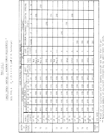
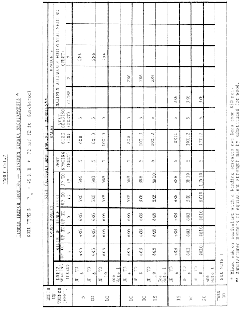
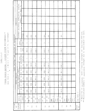
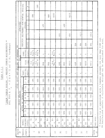
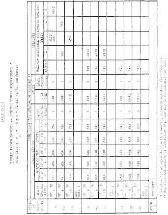
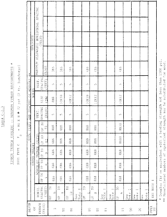
(1) Information is presented in tabular form in Tables C-1.1,
C-1.2, and C-1.3, and Tables C-2.1, C-2.2 and C-2.3 following
paragraph (g) of the appendix. Each table presents the minimum
sizes of timber members to use in a shoring system, and each table
contains data only for the particular soil type in which the
excavation or portion of the excavation is made. The data are
arranged to allow the user the flexibility to select from among
several acceptable configurations of members based on varying the
horizontal spacing of the crossbraces. Stable rock is exempt from
shoring requirements and therefore, no data are presented for this
condition.
(2) Information concerning the basis of the tabular data and the
limitations of the data is presented in paragraph (d) of this
appendix, and on the tables themselves.
(3) Information explaining the use of the tabular data is
presented in paragraph (e) of this appendix.
(4) Information illustrating the use of the tabular data is
presented in paragraph (f) of this appendix.
(5) Miscellaneous notations regarding Tables C-1.1 through C-1.3
and Tables C-2.1 through C-2.3 are presented in paragraph (g) of
this Appendix.
(d) Basis and limitations of the data - (1) Dimensions
of timber members. (i) The sizes of the timber members listed
in Tables C-1.1 through C-1.3 are taken from the National Bureau of
Standards (NBS) report, “Recommended Technical Provisions for
Construction Practice in Shoring and Sloping of Trenches and
Excavations.” In addition, where NBS did not recommend specific
sizes of members, member sizes are based on an analysis of the
sizes required for use by existing codes and on empirical
practice.
(ii) The required dimensions of the members listed in Tables
C-1.1 through C-1.3 refer to actual dimensions and not nominal
dimensions of the timber. Employers wanting to use nominal size
shoring are directed to Tables C-2.1 through C-2.3, or have this
choice under § 1926.652(c)(3), and are referred to The Corps of
Engineers, The Bureau of Reclamation or data from other acceptable
sources.
(2) Limitation of application. (i) It is not intended
that the timber shoring specification apply to every situation that
may be experienced in the field. These data were developed to apply
to the situations that are most commonly experienced in current
trenching practice. Shoring systems for use in situations that are
not covered by the data in this appendix must be designed as
specified in § 1926.652(c).
(ii) When any of the following conditions are present, the
members specified in the tables are not considered adequate. Either
an alternate timber shoring system must be designed or another type
of protective system designed in accordance with § 1926.652.
(A) When loads imposed by structures or by stored material
adjacent to the trench weigh in excess of the load imposed by a
two-foot soil surcharge. The term “adjacent” as used here means the
area within a horizontal distance from the edge of the trench equal
to the depth of the trench.
(B) When vertical loads imposed on cross braces exceed a
240-pound gravity load distributed on a one-foot section of the
center of the crossbrace.
(C) When surcharge loads are present from equipment weighing in
excess of 20,000 pounds.
(D) When only the lower portion of a trench is shored and the
remaining portion of the trench is sloped or benched unless: The
sloped portion is sloped at an angle less steep than three
horizontal to one vertical; or the members are selected from the
tables for use at a depth which is determined from the top of the
overall trench, and not from the toe of the sloped portion.
(e) Use of Tables. The members of the shoring system that
are to be selected using this information are the cross braces, the
uprights, and the wales, where wales are required. Minimum sizes of
members are specified for use in different types of soil. There are
six tables of information, two for each soil type. The soil type
must first be determined in accordance with the soil classification
system described in appendix A to subpart P of part 1926. Using the
appropriate table, the selection of the size and spacing of the
members is then made. The selection is based on the depth and width
of the trench where the members are to be installed and, in most
instances, the selection is also based on the horizontal spacing of
the crossbraces. Instances where a choice of horizontal spacing of
crossbracing is available, the horizontal spacing of the
crossbraces must be chosen by the user before the size of any
member can be determined. When the soil type, the width and depth
of the trench, and the horizontal spacing of the crossbraces are
known, the size and vertical spacing of the crossbraces, the size
and vertical spacing of the wales, and the size and horizontal
spacing of the uprights can be read from the appropriate table.
(f) Examples to Illustrate the Use of Tables C-1.1 through
C-1.3.
(1) Example 1.
A trench dug in Type A soil is 13 feet deep and five feet
wide.
From Table C-1.1, for acceptable arrangements of timber
can be used.
Arrangement #B1
Space 4 × 4 crossbraces at six feet horizontally and four feet
vertically.
Wales are not required.
Space 3 × 8 uprights at six feet horizontally. This arrangement
is commonly called “skip shoring.”
Arrangement #B2
Space 4 × 6 crossbraces at eight feet horizontally and four feet
vertically.
Space 8 × 8 wales at four feet vertically.
Space 2 × 6 uprights at four feet horizontally.
Arrangement #B3
Space 6 × 6 crossbraces at 10 feet horizontally and four feet
vertically.
Space 8 × 10 wales at four feet vertically.
Space 2 × 6 uprights at five feet horizontally.
Arrangement #B4
Space 6 × 6 crossbraces at 12 feet horizontally and four feet
vertically.
Space 10 × 10 wales at four feet vertically.
Spaces 3 × 8 uprights at six feet horizontally.
(2) Example 2.
A trench dug in Type B soil in 13 feet deep and five feet wide.
From Table C-1.2 three acceptable arrangements of members are
listed.
Arrangement #B1
Space 6 × 6 crossbraces at six feet horizontally and five feet
vertically.
Space 8 × 8 wales at five feet vertically.
Space 2 × 6 uprights at two feet horizontally.
Arrangement #B2
Space 6 × 8 crossbraces at eight feet horizontally and five feet
vertically.
Space 10 × 10 wales at five feet vertically.
Space 2 × 6 uprights at two feet horizontally.
Arrangement #B3
Space 8 × 8 crossbraces at 10 feet horizontally and five feet
vertically.
Space 10 × 12 wales at five feet vertically.
Space 2 × 6 uprights at two feet vertically.
(3) Example 3.
A trench dug in Type C soil is 13 feet deep and five feet
wide.
From Table C-1.3 two acceptable arrangements of members can be
used.
Arrangement #B1
Space 8 × 8 crossbraces at six feet horizontally and five feet
vertically.
Space 10 × 12 wales at five feet vertically.
Position 2 × 6 uprights as closely together as possible.
If water must be retained use special tongue and groove uprights
to form tight sheeting.
Arrangement #B2
Space 8 × 10 crossbraces at eight feet horizontally and five
feet vertically.
Space 12 × 12 wales at five feet vertically.
Position 2 × 6 uprights in a close sheeting configuration unless
water pressure must be resisted. Tight sheeting must be used where
water must be retained.
(4) Example 4.
A trench dug in Type C soil is 20 feet deep and 11 feet wide.
The size and spacing of members for the section of trench that is
over 15 feet in depth is determined using Table C-1.3. Only one
arrangement of members is provided.
Space 8 × 10 crossbraces at six feet horizontally and five feet
vertically.
Space 12 × 12 wales at five feet vertically.
Use 3 × 6 tight sheeting.
Use of Tables C-2.1 through C-2.3 would follow the same
procedures.
(g) Notes for all Tables.
1. Member sizes at spacings other than indicated are to be
determined as specified in § 1926.652(c), “Design of Protective
Systems.”
2. When conditions are saturated or submerged use Tight
Sheeting. Tight Sheeting refers to the use of specially-edged
timber planks (e.g., tongue and groove) at least three inches
thick, steel sheet piling, or similar construction that when driven
or placed in position provide a tight wall to resist the lateral
pressure of water and to prevent the loss of backfill material.
Close Sheeting refers to the placement of planks side-by-side
allowing as little space as possible between them.
3. All spacing indicated is measured center to center.
4. Wales to be installed with greater dimension horizontal.
5. If the vertical distance from the center of the lowest
crossbrace to the bottom of the trench exceeds two and one-half
feet, uprights shall be firmly embedded or a mudsill shall be used.
Where uprights are embedded, the vertical distance from the center
of the lowest crossbrace to the bottom of the trench shall not
exceed 36 inches. When mudsills are used, the vertical distance
shall not exceed 42 inches. Mudsills are wales that are installed
at the toe of the trench side.
6. Trench jacks may be used in lieu of or in combination with
timber crossbraces.
7. Placement cf crossbraces. When the vertical spacing of
crossbraces is four feet, place the top crossbrace no more than two
feet below the top of the trench. When the vertical spacing of
crossbraces is five feet, place the top crossbrace no more than 2.5
feet below the top of the trench.
Appendix C to Subpart V of Part 1926 - Protection From Hazardous Differences in Electric Potential
29:8.1.1.1.1.22.19.20.29 : Appendix C
Appendix C to Subpart V of Part 1926 - Protection From Hazardous
Differences in Electric Potential I. Introduction
Current passing through an impedance impresses voltage across
that impedance. Even conductors have some, albeit low, value of
impedance. Therefore, if a “grounded” 1 object, such as a crane or
deenergized and grounded power line, results in a ground fault on a
power line, voltage is impressed on that grounded object. The
voltage impressed on the grounded object depends largely on the
voltage on the line, on the impedance of the faulted conductor, and
on the impedance to “true,” or “absolute,” ground represented by
the object. If the impedance of the object causing the fault is
relatively large, the voltage impressed on the object is
essentially the phase-to-ground system voltage. However, even
faults to grounded power lines or to well grounded transmission
towers or substation structures (which have relatively low values
of impedance to ground) can result in hazardous voltages. 2 In all
cases, the degree of the hazard depends on the magnitude of the
current through the employee and the time of exposure. This
appendix discusses methods of protecting workers against the
possibility that grounded objects, such as cranes and other
mechanical equipment, will contact energized power lines and that
deenergized and grounded power lines will become accidentally
energized.
1 This appendix generally uses the term “grounded” only with
respect to grounding that the employer intentionally installs, for
example, the grounding an employer installs on a deenergized
conductor. However, in this case, the term “grounded” means
connected to earth, regardless of whether or not that connection is
intentional.
2 Thus, grounding systems for transmission towers and substation
structures should be designed to minimize the step and touch
potentials involved.
II. Voltage-Gradient Distribution
A. Voltage-gradient distribution curve. Absolute, or
true, ground serves as a reference and always has a voltage of 0
volts above ground potential. Because there is an impedance between
a grounding electrode and absolute ground, there will be a voltage
difference between the grounding electrode and absolute ground
under ground-fault conditions. Voltage dissipates from the
grounding electrode (or from the grounding point) and creates a
ground potential gradient. The voltage decreases rapidly with
increasing distance from the grounding electrode. A voltage drop
associated with this dissipation of voltage is a ground potential.
Figure 1 is a typical voltage-gradient distribution curve (assuming
a uniform soil texture).
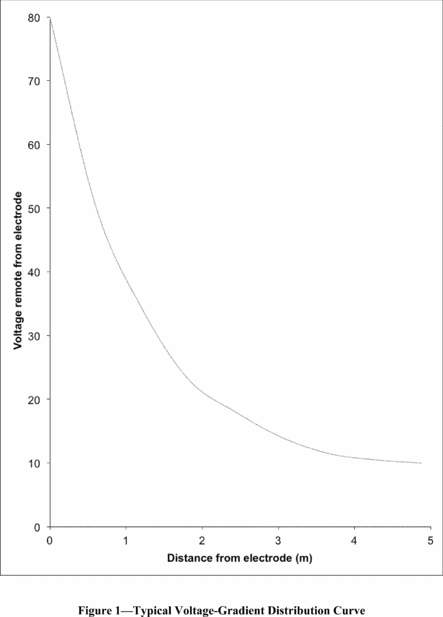
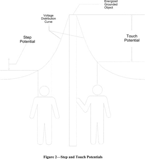
B. Step and touch potentials. Figure 1 also shows that
workers are at risk from step and touch potentials. Step potential
is the voltage between the feet of a person standing near an
energized grounded object (the electrode). In Figure 1, the step
potential is equal to the difference in voltage between two points
at different distances from the electrode (where the points
represent the location of each foot in relation to the electrode).
A person could be at risk of injury during a fault simply by
standing near the object.
Touch potential is the voltage between the energized grounded
object (again, the electrode) and the feet of a person in contact
with the object. In Figure 1, the touch potential is equal to the
difference in voltage between the electrode (which is at a distance
of 0 meters) and a point some distance away from the electrode
(where the point represents the location of the feet of the person
in contact with the object). The touch potential could be nearly
the full voltage across the grounded object if that object is
grounded at a point remote from the place where the person is in
contact with it. For example, a crane grounded to the system
neutral and that contacts an energized line would expose any person
in contact with the crane or its uninsulated load line to a touch
potential nearly equal to the full fault voltage.
Figure 2 illustrates step and touch potentials.
III.
Protecting Workers From Hazardous Differences in Electrical
Potential
A. Definitions. The following definitions apply to
section III of this appendix:
Bond. The electrical interconnection of conductive parts
designed to maintain a common electric potential.
Bonding cable (bonding jumper). A cable connected to two
conductive parts to bond the parts together.
Cluster bar. A terminal temporarily attached to a
structure that provides a means for the attachment and bonding of
grounding and bonding cables to the structure.
Ground. A conducting connection between an electric
circuit or equipment and the earth, or to some conducting body that
serves in place of the earth.
Grounding cable (grounding jumper). A cable connected
between a deenergized part and ground. Note that grounding cables
carry fault current and bonding cables generally do not. A cable
that bonds two conductive parts but carries substantial fault
current (for example, a jumper connected between one phase and a
grounded phase) is a grounding cable.
Ground mat (grounding grid). A temporarily or permanently
installed metallic mat or grating that establishes an equipotential
surface and provides connection points for attaching grounds.
B. Analyzing the hazard. The employer can use an
engineering analysis of the power system under fault conditions to
determine whether hazardous step and touch voltages will develop.
The analysis should determine the voltage on all conductive objects
in the work area and the amount of time the voltage will be
present. Based on the this analysis, the employer can select
appropriate measures and protective equipment, including the
measures and protective equipment outlined in Section III of this
appendix, to protect each employee from hazardous differences in
electric potential. For example, from the analysis, the employer
will know the voltage remaining on conductive objects after
employees install bonding and grounding equipment and will be able
to select insulating equipment with an appropriate rating, as
described in paragraph III.C.2 of this appendix.
C. Protecting workers on the ground. The employer may use
several methods, including equipotential zones, insulating
equipment, and restricted work areas, to protect employees on the
ground from hazardous differences in electrical potential.
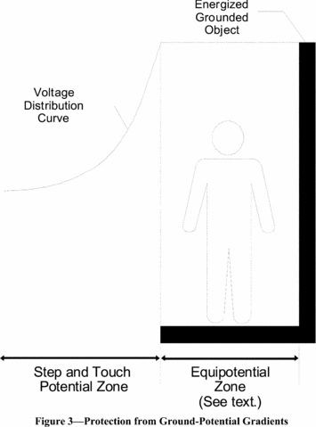
1. An equipotential zone will protect workers within it from
hazardous step and touch potentials. (See Figure 3.) Equipotential
zones will not, however, protect employees located either wholly or
partially outside the protected area. The employer can establish an
equipotential zone for workers on the ground, with respect to a
grounded object, through the use of a metal mat connected to the
grounded object. The employer can use a grounding grid to equalize
the voltage within the grid or bond conductive objects in the
immediate work area to minimize the potential between the objects
and between each object and ground. (Bonding an object outside the
work area can increase the touch potential to that object,
however.) Section III.D of this appendix discusses equipotential
zones for employees working on deenergized and grounded power
lines.
2. Insulating equipment, such as rubber gloves, can protect
employees handling grounded equipment and conductors from hazardous
touch potentials. The insulating equipment must be rated for the
highest voltage that can be impressed on the grounded objects under
fault conditions (rather than for the full system voltage).
3. Restricting employees from areas where hazardous step or
touch potentials could arise can protect employees not directly
involved in performing the operation. The employer must ensure that
employees on the ground in the vicinity of transmission structures
are at a distance where step voltages would be insufficient to
cause injury. Employees must not handle grounded conductors or
equipment likely to become energized to hazardous voltages unless
the employees are within an equipotential zone or protected by
insulating equipment.
D. Protecting employees working on deenergized and grounded
power lines. This Section III.D of Appendix C establishes
guidelines to help employers comply with requirements in § 1926.962
for using protective grounding to protect employees working on
deenergized power lines. Section 1926.962 applies to grounding of
transmission and distribution lines and equipment for the purpose
of protecting workers. Paragraph (c) of § 1926.962 requires
temporary protective grounds to be placed at such locations and
arranged in such a manner that the employer can demonstrate will
prevent exposure of each employee to hazardous differences in
electric potential. 3 Sections III.D.1 and III.D.2 of this appendix
provide guidelines that employers can use in making the
demonstration required by § 1926.962(c). Section III.D.1 of this
appendix provides guidelines on how the employer can determine
whether particular grounding practices expose employees to
hazardous differences in electric potential. Section III.D.2 of
this appendix describes grounding methods that the employer can use
in lieu of an engineering analysis to make the demonstration
required by § 1926.962(c). The Occupational Safety and Health
Administration will consider employers that comply with the
criteria in this appendix as meeting § 1926.962(c).
3 The protective grounding required by § 1926.962 limits to safe
values the potential differences between accessible objects in each
employee's work environment. Ideally, a protective grounding system
would create a true equipotential zone in which every point is at
the same electric potential. In practice, current passing through
the grounding and bonding elements creates potential differences.
If these potential differences are hazardous, the employer may not
treat the zone as an equipotential zone.
Finally, Section III.D.3 of this appendix discusses other safety
considerations that will help the employer comply with other
requirements in § 1926.962. Following these guidelines will protect
workers from hazards that can occur when a deenergized and grounded
line becomes energized.
1. Determining safe body current limits. This Section
III.D.1 of Appendix C provides guidelines on how an employer can
determine whether any differences in electric potential to which
workers could be exposed are hazardous as part of the demonstration
required by § 1926.962(c).
Institute of Electrical and Electronic Engineers (IEEE) Standard
1048-2003, IEEE Guide for Protective Grounding of Power
Lines, provides the following equation for determining the
threshold of ventricular fibrillation when the duration of the
electric shock is limited:

where
I is the current through the worker's body, and
t is
the duration of the current in seconds. This equation represents
the ventricular fibrillation threshold for 95.5 percent of the
adult population with a mass of 50 kilograms (110 pounds) or more.
The equation is valid for current durations between 0.0083 to 3.0
seconds.
To use this equation to set safe voltage limits in an
equipotential zone around the worker, the employer will need to
assume a value for the resistance of the worker's body. IEEE Std
1048-2003 states that “total body resistance is usually taken as
1000 Ω for determining . . . body current limits.” However,
employers should be aware that the impedance of a worker's body can
be substantially less than that value. For instance, IEEE Std
1048-2003 reports a minimum hand-to-hand resistance of 610 ohms and
an internal body resistance of 500 ohms. The internal resistance of
the body better represents the minimum resistance of a worker's
body when the skin resistance drops near zero, which occurs, for
example, when there are breaks in the worker's skin, for instance,
from cuts or from blisters formed as a result of the current from
an electric shock, or when the worker is wet at the points of
contact.
Employers may use the IEEE Std 1048-2003 equation to determine
safe body current limits only if the employer protects workers from
hazards associated with involuntary muscle reactions from electric
shock (for example, the hazard to a worker from falling as a result
of an electric shock). Moreover, the equation applies only when the
duration of the electric shock is limited. If the precautions the
employer takes, including those required by applicable standards,
do not adequately protect employees from hazards associated with
involuntary reactions from electric shock, a hazard exists if the
induced voltage is sufficient to pass a current of 1 milliampere
through a 500-ohm resistor. (The 500-ohm resistor represents the
resistance of an employee. The 1-milliampere current is the
threshold of perception.) Finally, if the employer protects
employees from injury due to involuntary reactions from electric
shock, but the duration of the electric shock is unlimited (that
is, when the fault current at the work location will be
insufficient to trip the devices protecting the circuit), a hazard
exists if the resultant current would be more than 6 milliamperes
(the recognized let-go threshold for workers 4 ).
4 Electric current passing through the body has varying effects
depending on the amount of the current. At the let-go threshold,
the current overrides a person's control over his or her muscles.
At that level, an employee grasping an object will not be able to
let go of the object. The let-go threshold varies from person to
person; however, the recognized value for workers is 6
milliamperes.
2. Acceptable methods of grounding for employers that do not
perform an engineering determination. The grounding methods
presented in this section of this appendix ensure that differences
in electric potential are as low as possible and, therefore, meet §
1926.962(c) without an engineering determination of the potential
differences. These methods follow two principles: (i) The grounding
method must ensure that the circuit opens in the fastest available
clearing time, and (ii) the grounding method must ensure that the
potential differences between conductive objects in the employee's
work area are as low as possible.
Paragraph (c) of § 1926.962 does not require grounding methods
to meet the criteria embodied in these principles. Instead, the
paragraph requires that protective grounds be “placed at such
locations and arranged in such a manner that the employer can
demonstrate will prevent exposure of each employee to hazardous
differences in electric potential.” However, when the employer's
grounding practices do not follow these two principles, the
employer will need to perform an engineering analysis to make the
demonstration required by § 1926.962(c).
i. Ensuring that the circuit opens in the fastest available
clearing time. Generally, the higher the fault current, the
shorter the clearing times for the same type of fault. Therefore,
to ensure the fastest available clearing time, the grounding method
must maximize the fault current with a low impedance connection to
ground. The employer accomplishes this objective by grounding the
circuit conductors to the best ground available at the worksite.
Thus, the employer must ground to a grounded system neutral
conductor, if one is present. A grounded system neutral has a
direct connection to the system ground at the source, resulting in
an extremely low impedance to ground. In a substation, the employer
may instead ground to the substation grid, which also has an
extremely low impedance to the system ground and, typically, is
connected to a grounded system neutral when one is present. Remote
system grounds, such as pole and tower grounds, have a higher
impedance to the system ground than grounded system neutrals and
substation grounding grids; however, the employer may use a remote
ground when lower impedance grounds are not available. In the
absence of a grounded system neutral, substation grid, and remote
ground, the employer may use a temporary driven ground at the
worksite.
In addition, if employees are working on a three-phase system,
the grounding method must short circuit all three phases. Short
circuiting all phases will ensure faster clearing and lower the
current through the grounding cable connecting the deenergized line
to ground, thereby lowering the voltage across that cable. The
short circuit need not be at the worksite; however, the employer
must treat any conductor that is not grounded at the worksite as
energized because the ungrounded conductors will be energized at
fault voltage during a fault.
ii. Ensuring that the potential differences between
conductive objects in the employee's work area are as low as
possible. To achieve as low a voltage as possible across any
two conductive objects in the work area, the employer must bond all
conductive objects in the work area. This section of this appendix
discusses how to create a zone that minimizes differences in
electric potential between conductive objects in the work area.
The employer must use bonding cables to bond conductive objects,
except for metallic objects bonded through metal-to-metal contact.
The employer must ensure that metal-to-metal contacts are tight and
free of contamination, such as oxidation, that can increase the
impedance across the connection. For example, a bolted connection
between metal lattice tower members is acceptable if the connection
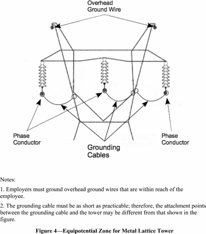
is tight and free of corrosion and other contamination. Figure 4
shows how to create an equipotential zone for metal lattice
towers.
Wood poles are conductive objects. The poles can absorb moisture
and conduct electricity, particularly at distribution and
transmission voltages. Consequently, the employer must either: (1)
Provide a conductive platform, bonded to a grounding cable, on
which the worker stands or (2) use cluster bars to bond wood poles
to the grounding cable. The employer must ensure that employees
install the cluster bar below, and close to, the worker's feet. The
inner portion of the wood pole is more conductive than the outer
shell, so it is important that the cluster bar be in conductive
contact with a metal spike or nail that penetrates the wood to a
depth greater than or equal to the depth the worker's climbing
gaffs will penetrate the wood. For example, the employer could
mount the cluster bar on a bare pole ground wire fastened to the
pole with nails or staples that penetrate to the required depth.
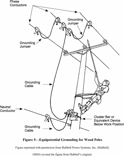
Alternatively, the employer may temporarily nail a conductive strap
to the pole and connect the strap to the cluster bar. Figure 5
shows how to create an equipotential zone for wood poles.
For underground systems, employers commonly install grounds at
the points of disconnection of the underground cables. These
grounding points are typically remote from the manhole or
underground vault where employees will be working on the cable.
Workers in contact with a cable grounded at a remote location can
experience hazardous potential differences if the cable becomes
energized or if a fault occurs on a different, but nearby,
energized cable. The fault current causes potential gradients in
the earth, and a potential difference will exist between the earth
where the worker is standing and the earth where the cable is
grounded. Consequently, to create an equipotential zone for the
worker, the employer must provide a means of connecting the
deenergized cable to ground at the worksite by having the worker
stand on a conductive mat bonded to the deenergized cable. If the
cable is cut, the employer must install a bond across the opening
in the cable or install one bond on each side of the opening to
ensure that the separate cable ends are at the same potential. The
employer must protect the worker from any hazardous differences in
potential any time there is no bond between the mat and the cable
(for example, before the worker installs the bonds).
3. Other safety-related considerations. To ensure that
the grounding system is safe and effective, the employer should
also consider the following factors: 5
5 This appendix only discusses factors that relate to ensuring
an equipotential zone for employees. The employer must consider
other factors in selecting a grounding system that is capable of
conducting the maximum fault current that could flow at the point
of grounding for the time necessary to clear the fault, as required
by § 1926.962(d)(1)(i). IEEE Std 1048-2003 contains guidelines for
selecting and installing grounding equipment that will meet §
1926.962(d)(1)(i).
i. Maintenance of grounding equipment. It is essential
that the employer properly maintain grounding equipment. Corrosion
in the connections between grounding cables and clamps and on the
clamp surface can increase the resistance of the cable, thereby
increasing potential differences. In addition, the surface to which
a clamp attaches, such as a conductor or tower member, must be
clean and free of corrosion and oxidation to ensure a
low-resistance connection. Cables must be free of damage that could
reduce their current-carrying capacity so that they can carry the
full fault current without failure. Each clamp must have a tight
connection to the cable to ensure a low resistance and to ensure
that the clamp does not separate from the cable during a fault.
ii. Grounding cable length and movement. The
electromagnetic forces on grounding cables during a fault increase
with increasing cable length. These forces can cause the cable to
move violently during a fault and can be high enough to damage the
cable or clamps and cause the cable to fail. In addition, flying
cables can injure workers. Consequently, cable lengths should be as
short as possible, and grounding cables that might carry high fault
current should be in positions where the cables will not injure
workers during a fault.
Appendix C to Subpart CC of Part 1926 - Operator Certification: Written Examination: Technical Knowledge Criteria
29:8.1.1.1.1.29.25.45.39 : Appendix C
Appendix C to Subpart CC of Part 1926 - Operator Certification:
Written Examination: Technical Knowledge Criteria
This appendix contains information for employers, accredited
testing organizations, auditors and government entities developing
criteria for a written examination to test an individual's
technical knowledge relating to the operation of cranes.
(a) General technical information.
(1) The functions and limitations of the crane and
attachments.
(2) Wire rope:
(i) Background information necessary to understand the
inspection and removal from service criteria in § 1926.1413 and §
1926.1414.
(ii) Capacity and when multi-part rope is needed.
(iii) Relationship between line pull and safe working load.
(iv) How to determine the manufacturer's recommended rope for
the crane.
(3) Rigging devices and their use, such as:
(i) Slings.
(ii) Spreaders.
(iii) Lifting beams.
(iv) Wire rope fittings, such as clips, shackles and wedge
sockets.
(v) Saddles (softeners).
(vi) Clamps (beams).
(4) The technical limitations of protective measures against
electrical hazards:
(i) Grounding.
(ii) Proximity warning devices.
(iii) Insulated links.
(iv) Boom cages.
(v) Proximity to electric power lines, radii, and microwave
structures.
(5) The effects of load share and load transfer in multi-crane
lifts.
(6) Basic crane terms.
(7) The basics of machine power flow systems.
(i) Mechanical.
(ii) Electrical.
(iii) Pneumatic.
(iv) Hydraulic.
(v) Combination.
(8) The significance of the instruments and gauge readings.
(9) The effects of thermal expansion and contraction in
hydraulic cylinders.
(10) Background information necessary to understand the
requirements of pre-operation and inspection.
(11) How to use the safety devices and operational aids required
under § 1926.1415 and § 1926.1416.
(12) The difference between duty-cycle and lifting
operations.
(13) How to calculate net capacity for every possible
configuration of the equipment using the manufacturer's load
chart.
(14) How to use manufacturer-approved attachments and their
effect on the equipment.
(15) How to obtain dimensions, weight, and center of gravity of
the load.
(16) The effects of dynamic loading from:
(i) Wind.
(ii) Stopping and starting.
(iii) Impact loading.
(iv) Moving with the load.
(17) The effect of side loading.
(18) The principles of backward stability.
(b) Site information.
(1) How to identify the suitability of the supporting
ground/surface to support the expected loads of the operation.
Elements include:
(i) Weaknesses below the surface (such as voids, tanks, loose
fill).
(ii) Weaknesses on the surface (such as retaining walls, slopes,
excavations, depressions).
(2) Proper use of mats, blocking/cribbing, outriggers,
stabilizers, or crawlers.
(3) Identification of site hazards such as power lines, piping,
and traffic.
(4) How to review operation plans with supervisors and other
workers (such as the signal person), including how to determine
working height, boom length, load radius, and travel clearance.
(5) How to determine if there is adequate room for extension of
crawlers or outriggers/stabilizers and counterweights.
(c) Operations.
(1) How to pick, carry, swing and place the load smoothly and
safely on rubber tires and on outriggers/stabilizers or crawlers
(where applicable).
(2) How to communicate at the site with supervisors, the crew
and the signal person.
(3) Proper procedures and methods of reeving wire ropes and
methods of reeving multiple-part lines and selecting the proper
load block and/or ball.
(4) How to react to changes in conditions that affect the safe
operation of the equipment.
(5) How to shut down and secure the equipment properly when
leaving it unattended.
(6) Know how to apply the manufacturer's specifications for
operating in various weather conditions, and understand how
environmental conditions affect the safe operation of the
equipment.
(7) How to properly level the equipment.
(8) How to verify the weight of the load and rigging prior to
initiating the lift.
(9) How to determine where the load is to be picked up and
placed and how to verify the radii.
(10) Know basic rigging procedures.
(11) How to carry out the shift inspection required in this
subpart.
(12) Know that the following operations require specific
procedures and skill levels:
(i) Multi-crane lifts.
(ii) Hoisting personnel.
(iii) Clamshell/dragline operations.
(iv) Pile driving and extracting.
(v) Concrete operations, including poured-in-place and
tilt-up.
(vi) Demolition operations.
(vii) Operations on water.
(viii) Magnet operations.
(ix) Multi-drum operations.
(13) Know the proper procedures for operating safely under the
following conditions:
(i) Traveling with suspended loads.
(ii) Approaching a two-block condition.
(iii) Operating near power lines.
(iv) Hoisting personnel.
(v) Using other than full outrigger/crawler or stabilizer
extensions.
(vi) Lifting loads from beneath the surface of the water.
(vii) Using various approved counterweight configurations.
(viii) Handling loads out of the operator's vision (“operating
in the blind”).
(ix) Using electronic communication systems for signal
communication.
(14) Know the proper procedures for load control and the use of
hand-held tag lines.
(15) Know the emergency response procedure for:
(i) Fires.
(ii) Power line contact.
(iii) Loss of stability.
(iv) Control malfunction.
(v) Two-blocking.
(vi) Overload.
(vii) Carrier or travel malfunction.
(16) Know how to properly use outriggers and stabilizers in
accordance with manufacturer specifications.
(d) Use of load charts.
(1) Know the terminology necessary to use load charts.
(2) Know how to ensure that the load chart is the appropriate
chart for the equipment in its particular configuration and
application.
(3) Know how to use load charts. This includes knowing:
(i) The operational limitations of load charts and
footnotes.
(ii) How to relate the chart to the configuration of the crane,
crawlers, or outriggers/stabilizers extended or retracted, jib
erected or offset, and various counterweight configurations.
(iii) The difference between structural capacity and capacity
limited by stability.
(iv) What is included in capacity ratings.
(v) The range diagram and its relationship to the load
chart.
(vi) The work area chart and its relationship to the load
chart.
(vii) Where to find and how to use the “parts-of-line”
information.
(4) Know how to use the load chart together with the load
indicators and/or load moment devices.