Title 29
PART 1926 APPENDIX B
| 72.6 to 420.0 kilovolts | 3.5 per unit. |
| 420.1 to 550.0 kilovolts | 3.0 per unit. |
| 550.1 to 800.0 kilovolts | 2.5 per unit. |
See paragraph IV.A.2, later in this appendix, for additional discussion of maximum transient overvoltages.
D. Types of exposures. Employees working on or near energized electric power generation, transmission, and distribution systems face two kinds of exposures: Phase-to-ground and phase-to-phase. The exposure is phase-to-ground: (1) With respect to an energized part, when the employee is at ground potential or (2) with respect to ground, when an employee is at the potential of the energized part during live-line barehand work. The exposure is phase-to-phase, with respect to an energized part, when an employee is at the potential of another energized part (at a different potential) during live-line barehand work.
III. Determination of Minimum Approach Distances for AC Voltages Greater Than 300 VoltsA. Voltages of 301 to 5,000 volts. Test data generally forms the basis of minimum air insulation distances. The lowest voltage for which sufficient test data exists is 5,000 volts, and these data indicate that the minimum air insulation distance at that voltage is 20 millimeters (1 inch). Because the minimum air insulation distance increases with increasing voltage, and, conversely, decreases with decreasing voltage, an assumed minimum air insulation distance of 20 millimeters will protect against sparkover at voltages of 301 to 5,000 volts. Thus, 20 millimeters is the electrical component of the minimum approach distance for these voltages.
B. Voltages of 5.1 to 72.5 kilovolts. For voltages from 5.1 to 72.5 kilovolts, the Occupational Safety and Health Administration bases the methodology for calculating the electrical component of the minimum approach distance on Institute of Electrical and Electronic Engineers (IEEE) Standard 4-1995, Standard Techniques for High-Voltage Testing. Table 1 lists the critical sparkover distances from that standard as listed in IEEE Std 516-2009, IEEE Guide for Maintenance Methods on Energized Power Lines.
Table 1 - Sparkover Distance for Rod-to-Rod Gap
| 60 Hz rod-to-rod
sparkover (kV peak) |
Gap spacing from IEEE Std
4-1995 (cm) |
|---|---|
| 25 | 2 |
| 36 | 3 |
| 46 | 4 |
| 53 | 5 |
| 60 | 6 |
| 70 | 8 |
| 79 | 10 |
| 86 | 12 |
| 95 | 14 |
| 104 | 16 |
| 112 | 18 |
| 120 | 20 |
| 143 | 25 |
| 167 | 30 |
| 192 | 35 |
| 218 | 40 |
| 243 | 45 |
| 270 | 50 |
| 322 | 60 |
Source: IEEE Std 516-2009.
To use this table to determine the electrical component of the minimum approach distance, the employer must determine the peak phase-to-ground transient overvoltage and select a gap from the table that corresponds to that voltage as a withstand voltage rather than a critical sparkover voltage. To calculate the electrical component of the minimum approach distance for voltages between 5 and 72.5 kilovolts, use the following procedure:
1. Divide the phase-to-phase voltage by the square root of 3 to convert it to a phase-to-ground voltage.
2. Multiply the phase-to-ground voltage by the square root of 2 to convert the rms value of the voltage to the peak phase-to-ground voltage.
3. Multiply the peak phase-to-ground voltage by the maximum per-unit transient overvoltage, which, for this voltage range, is 3.0, as discussed later in this appendix. This is the maximum phase-to-ground transient overvoltage, which corresponds to the withstand voltage for the relevant exposure. 3
3 The withstand voltage is the voltage at which sparkover is not likely to occur across a specified distance. It is the voltage taken at the 3σ point below the sparkover voltage, assuming that the sparkover curve follows a normal distribution.
4. Divide the maximum phase-to-ground transient overvoltage by 0.85 to determine the corresponding critical sparkover voltage. (The critical sparkover voltage is 3 standard deviations (or 15 percent) greater than the withstand voltage.)
5. Determine the electrical component of the minimum approach distance from Table 1 through interpolation.
Table 2 illustrates how to derive the electrical component of the minimum approach distance for voltages from 5.1 to 72.5 kilovolts, before the application of any altitude correction factor, as explained later.
Table 2 - Calculating the Electrical Component of MAD - 751 V to 72.5 kV
| Step | Maximum system phase-to-phase voltage (kV) | |||
|---|---|---|---|---|
| 15 | 36 | 46 | 72.5 | |
| 1. Divide by √3 | 8.7 | 20.8 | 26.6 | 41.9 |
| 2. Multiply by √2 | 12.2 | 29.4 | 37.6 | 59.2 |
| 3. Multiply by 3.0 | 36.7 | 88.2 | 112.7 | 177.6 |
| 4. Divide by 0.85 | 43.2 | 103.7 | 132.6 | 208.9 |
| 5. Interpolate from Table 1 | 3 + (7.2/10) 1 | 14 + (8.7/9)*2 | 20 + (12.6/23)*5 | 35 + (16.9/26)*5 |
| Electrical component of MAD (cm) | 3.72 | 15.93 | 22.74 | 38.25 |
C. Voltages of 72.6 to 800 kilovolts. For voltages of 72.6 kilovolts to 800 kilovolts, this subpart bases the electrical component of minimum approach distances, before the application of any altitude correction factor, on the following formula:
Equation 1 - For voltages of 72.6 kV to 800 kV D = 0.3048(C + a)VL-GT Where: D = Electrical component of the minimum approach distance in air in meters; C = a correction factor associated with the variation of gap sparkover with voltage;a = A factor relating to the saturation of air at system voltages of 345 kilovolts or higher; 4
4 Test data demonstrates that the saturation factor is greater than 0 at peak voltages of about 630 kilovolts. Systems operating at 345 kilovolts (or maximum system voltages of 362 kilovolts) can have peak maximum transient overvoltages exceeding 630 kilovolts. Table V-2 sets equations for calculating a based on peak voltage.
VL-G = Maximum system line-to-ground rms voltage in kilovolts - it should be the “actual” maximum, or the normal highest voltage for the range (for example, 10 percent above the nominal voltage); and
T = Maximum transient overvoltage factor in per unit.In Equation 1, C is 0.01: (1) For phase-to-ground exposures that the employer can demonstrate consist only of air across the approach distance (gap) and (2) for phase-to-phase exposures if the employer can demonstrate that no insulated tool spans the gap and that no large conductive object is in the gap. Otherwise, C is 0.011.
In Equation 1, the term a varies depending on whether the employee's exposure is phase-to-ground or phase-to-phase and on whether objects are in the gap. The employer must use the equations in Table 3 to calculate a. Sparkover test data with insulation spanning the gap form the basis for the equations for phase-to-ground exposures, and sparkover test data with only air in the gap form the basis for the equations for phase-to-phase exposures. The phase-to-ground equations result in slightly higher values of a, and, consequently, produce larger minimum approach distances, than the phase-to-phase equations for the same value of VPeak.
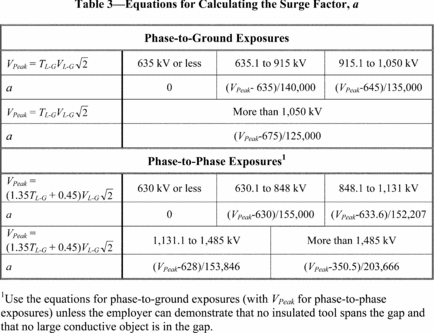
In Equation 1, T is the maximum transient overvoltage factor in per unit. As noted earlier, § 1926.960(c)(1)(ii) requires the employer to determine the maximum anticipated per-unit transient overvoltage, phase-to-ground, through an engineering analysis or assume a maximum anticipated per-unit transient overvoltage, phase-to-ground, in accordance with Table V-8. For phase-to-ground exposures, the employer uses this value, called TL-G, as T in Equation 1. IEEE Std 516-2009 provides the following formula to calculate the phase-to-phase maximum transient overvoltage, TL-L, from TL-G:
TL-L = 1.35TL-G + 0.45. For phase-to-phase exposures, the employer uses this value as T in Equation 1.D. Provisions for inadvertent movement. The minimum approach distance must include an “adder” to compensate for the inadvertent movement of the worker relative to an energized part or the movement of the part relative to the worker. This “adder” must account for this possible inadvertent movement and provide the worker with a comfortable and safe zone in which to work. Employers must add the distance for inadvertent movement (called the “ergonomic component of the minimum approach distance”) to the electrical component to determine the total safe minimum approach distances used in live-line work.
The Occupational Safety and Health Administration based the ergonomic component of the minimum approach distance on response time-distance analysis. This technique uses an estimate of the total response time to a hazardous incident and converts that time to the distance traveled. For example, the driver of a car takes a given amount of time to respond to a “stimulus” and stop the vehicle. The elapsed time involved results in the car's traveling some distance before coming to a complete stop. This distance depends on the speed of the car at the time the stimulus appears and the reaction time of the driver.
In the case of live-line work, the employee must first perceive that he or she is approaching the danger zone. Then, the worker responds to the danger and must decelerate and stop all motion toward the energized part. During the time it takes to stop, the employee will travel some distance. This is the distance the employer must add to the electrical component of the minimum approach distance to obtain the total safe minimum approach distance.
At voltages from 751 volts to 72.5 kilovolts, 5 the electrical component of the minimum approach distance is smaller than the ergonomic component. At 72.5 kilovolts, the electrical component is only a little more than 0.3 meters (1 foot). An ergonomic component of the minimum approach distance must provide for all the worker's unanticipated movements. At these voltages, workers generally use rubber insulating gloves; however, these gloves protect only a worker's hands and arms. Therefore, the energized object must be at a safe approach distance to protect the worker's face. In this case, 0.61 meters (2 feet) is a sufficient and practical ergonomic component of the minimum approach distance.
5 For voltages of 50 to 300 volts, Table V-2 specifies a minimum approach distance of “avoid contact.” The minimum approach distance for this voltage range contains neither an electrical component nor an ergonomic component.
For voltages between 72.6 and 800 kilovolts, employees must use different work practices during energized line work. Generally, employees use live-line tools (hot sticks) to perform work on energized equipment. These tools, by design, keep the energized part at a constant distance from the employee and, thus, maintain the appropriate minimum approach distance automatically.
The location of the worker and the type of work methods the worker is using also influence the length of the ergonomic component of the minimum approach distance. In this higher voltage range, the employees use work methods that more tightly control their movements than when the workers perform work using rubber insulating gloves. The worker, therefore, is farther from the energized line or equipment and must be more precise in his or her movements just to perform the work. For these reasons, this subpart adopts an ergonomic component of the minimum approach distance of 0.31 m (1 foot) for voltages between 72.6 and 800 kilovolts.
Table 4 summarizes the ergonomic component of the minimum approach distance for various voltage ranges.
Table 4 - Ergonomic Component of Minimum Approach Distance
| Voltage range (kV) | Distance | |
|---|---|---|
| m | ft | |
| 0.301 to 0.750 | 0.31 | 1.0 |
| 0.751 to 72.5 | 0.61 | 2.0 |
| 72.6 to 800 | 0.31 | 1.0 |
Note: The employer must add this distance to the electrical component of the minimum approach distance to obtain the full minimum approach distance.
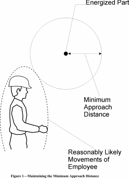
The ergonomic component of the minimum approach distance accounts for errors in maintaining the minimum approach distance (which might occur, for example, if an employee misjudges the length of a conductive object he or she is holding), and for errors in judging the minimum approach distance. The ergonomic component also accounts for inadvertent movements by the employee, such as slipping. In contrast, the working position selected to properly maintain the minimum approach distance must account for all of an employee's reasonably likely movements and still permit the employee to adhere to the applicable minimum approach distance. (See Figure 1.) Reasonably likely movements include an employee's adjustments to tools, equipment, and working positions and all movements needed to perform the work. For example, the employee should be able to perform all of the following actions without straying into the minimum approach distance:
• Adjust his or her hardhat,
• maneuver a tool onto an energized part with a reasonable amount of overreaching or underreaching,
• reach for and handle tools, material, and equipment passed to him or her, and
• adjust tools, and replace components on them, when necessary during the work procedure.
The training of qualified employees required under § 1926.950, and the job planning and briefing required under § 1926.952, must address selection of a proper working position.
E. Miscellaneous correction factors. Changes in the air medium that forms the insulation influences the strength of an air gap. A brief discussion of each factor follows.
1. Dielectric strength of air. The dielectric strength of air in a uniform electric field at standard atmospheric conditions is approximately 3 kilovolts per millimeter. 6 The pressure, temperature, and humidity of the air, the shape, dimensions, and separation of the electrodes, and the characteristics of the applied voltage (wave shape) affect the disruptive gradient.
6 For the purposes of estimating arc length, Subpart V generally assumes a more conservative dielectric strength of 10 kilovolts per 25.4 millimeters, consistent with assumptions made in consensus standards such as the National Electrical Safety Code (IEEE C2-2012). The more conservative value accounts for variables such as electrode shape, wave shape, and a certain amount of overvoltage.
2. Atmospheric effect. The empirically determined electrical strength of a given gap is normally applicable at standard atmospheric conditions (20 °C, 101.3 kilopascals, 11 grams/cubic centimeter humidity). An increase in the density (humidity) of the air inhibits sparkover for a given air gap. The combination of temperature and air pressure that results in the lowest gap sparkover voltage is high temperature and low pressure. This combination of conditions is not likely to occur. Low air pressure, generally associated with high humidity, causes increased electrical strength. An average air pressure generally correlates with low humidity. Hot and dry working conditions normally result in reduced electrical strength. The equations for minimum approach distances in Table V-2 assume standard atmospheric conditions.
3. Altitude. The reduced air pressure at high altitudes causes a reduction in the electrical strength of an air gap. An employer must increase the minimum approach distance by about 3 percent per 300 meters (1,000 feet) of increased altitude for altitudes above 900 meters (3,000 feet). Table V-4 specifies the altitude correction factor that the employer must use in calculating minimum approach distances.
IV. Determining Minimum Approach Distances A. Factors Affecting Voltage Stress at the Worksite1. System voltage (nominal). The nominal system voltage range determines the voltage for purposes of calculating minimum approach distances. The employer selects the range in which the nominal system voltage falls, as given in the relevant table, and uses the highest value within that range in per-unit calculations.
2. Transient overvoltages. Operation of switches or circuit breakers, a fault on a line or circuit or on an adjacent circuit, and similar activities may generate transient overvoltages on an electrical system. Each overvoltage has an associated transient voltage wave shape. The wave shape arriving at the site and its magnitude vary considerably.
In developing requirements for minimum approach distances, the Occupational Safety and Health Administration considered the most common wave shapes and the magnitude of transient overvoltages found on electric power generation, transmission, and distribution systems. The equations in Table V-2 for minimum approach distances use per-unit maximum transient overvoltages, which are relative to the nominal maximum voltage of the system. For example, a maximum transient overvoltage value of 3.0 per unit indicates that the highest transient overvoltage is 3.0 times the nominal maximum system voltage.
3. Typical magnitude of overvoltages. Table 5 lists the magnitude of typical transient overvoltages.
Table 5 - Magnitude of Typical Transient Overvoltages
| Cause | Magnitude (per unit) |
|---|---|
| Energized 200-mile line without closing resistors | 3.5 |
| Energized 200-mile line with one-step closing resistor | 2.1 |
| Energized 200-mile line with multistep resistor | 2.5 |
| Reclosing with trapped charge one-step resistor | 2.2 |
| Opening surge with single restrike | 3.0 |
| Fault initiation unfaulted phase | 2.1 |
| Fault initiation adjacent circuit | 2.5 |
| Fault clearing | 1.7 to 1.9 |
4. Standard deviation - air-gap withstand. For each air gap length under the same atmospheric conditions, there is a statistical variation in the breakdown voltage. The probability of breakdown against voltage has a normal (Gaussian) distribution. The standard deviation of this distribution varies with the wave shape, gap geometry, and atmospheric conditions. The withstand voltage of the air gap is three standard deviations (3σ) below the critical sparkover voltage. (The critical sparkover voltage is the crest value of the impulse wave that, under specified conditions, causes sparkover 50 percent of the time. An impulse wave of three standard deviations below this value, that is, the withstand voltage, has a probability of sparkover of approximately 1 in 1,000.)
5. Broken Insulators. Tests show reductions in the insulation strength of insulator strings with broken skirts. Broken units may lose up to 70 percent of their withstand capacity. Because an employer cannot determine the insulating capability of a broken unit without testing it, the employer must consider damaged units in an insulator to have no insulating value. Additionally, the presence of a live-line tool alongside an insulator string with broken units may further reduce the overall insulating strength. The number of good units that must be present in a string for it to be “insulated” as defined by § 1926.968 depends on the maximum overvoltage possible at the worksite.
B. Minimum Approach Distances Based on Known, Maximum-Anticipated Per-Unit Transient Overvoltages1. Determining the minimum approach distance for AC systems. Under § 1926.960(c)(1)(ii), the employer must determine the maximum anticipated per-unit transient overvoltage, phase-to-ground, through an engineering analysis or must assume a maximum anticipated per-unit transient overvoltage, phase-to-ground, in accordance with Table V-8. When the employer conducts an engineering analysis of the system and determines that the maximum transient overvoltage is lower than specified by Table V-8, the employer must ensure that any conditions assumed in the analysis, for example, that employees block reclosing on a circuit or install portable protective gaps, are present during energized work. To ensure that these conditions are present, the employer may need to institute new live-work procedures reflecting the conditions and limitations set by the engineering analysis.
2. Calculation of reduced approach distance values. An employer may take the following steps to reduce minimum approach distances when the maximum transient overvoltage on the system (that is, the maximum transient overvoltage without additional steps to control overvoltages) produces unacceptably large minimum approach distances:
Step 1. Determine the maximum voltage (with respect to a given nominal voltage range) for the energized part.
Step 2. Determine the technique to use to control the maximum transient overvoltage. (See paragraphs IV.C and IV.D of this appendix.) Determine the maximum transient overvoltage that can exist at the worksite with that form of control in place and with a confidence level of 3σ . This voltage is the withstand voltage for the purpose of calculating the appropriate minimum approach distance.
Step 3. Direct employees to implement procedures to ensure that the control technique is in effect during the course of the work.
Step 4. Using the new value of transient overvoltage in per unit, calculate the required minimum approach distance from Table V-2.
C. Methods of Controlling Possible Transient Overvoltage Stress Found on a System1. Introduction. There are several means of controlling overvoltages that occur on transmission systems. For example, the employer can modify the operation of circuit breakers or other switching devices to reduce switching transient overvoltages. Alternatively, the employer can hold the overvoltage to an acceptable level by installing surge arresters or portable protective gaps on the system. In addition, the employer can change the transmission system to minimize the effect of switching operations. Section 4.8 of IEEE Std 516-2009 describes various ways of controlling, and thereby reducing, maximum transient overvoltages.
2. Operation of circuit breakers. 7 The maximum transient overvoltage that can reach the worksite is often the result of switching on the line on which employees are working. Disabling automatic reclosing during energized line work, so that the line will not be reenergized after being opened for any reason, limits the maximum switching surge overvoltage to the larger of the opening surge or the greatest possible fault-generated surge, provided that the devices (for example, insertion resistors) are operable and will function to limit the transient overvoltage and that circuit breaker restrikes do not occur. The employer must ensure the proper functioning of insertion resistors and other overvoltage-limiting devices when the employer's engineering analysis assumes their proper operation to limit the overvoltage level. If the employer cannot disable the reclosing feature (because of system operating conditions), other methods of controlling the switching surge level may be necessary.
7 The detailed design of a circuit interrupter, such as the design of the contacts, resistor insertion, and breaker timing control, are beyond the scope of this appendix. The design of the system generally accounts for these features. This appendix only discusses features that can limit the maximum switching transient overvoltage on a system.
Transient surges on an adjacent line, particularly for double circuit construction, may cause a significant overvoltage on the line on which employees are working. The employer's engineering analysis must account for coupling to adjacent lines.
3. Surge arresters. The use of modern surge arresters allows a reduction in the basic impulse-insulation levels of much transmission system equipment. The primary function of early arresters was to protect the system insulation from the effects of lightning. Modern arresters not only dissipate lightning-caused transients, but may also control many other system transients caused by switching or faults.
The employer may use properly designed arresters to control transient overvoltages along a transmission line and thereby reduce the requisite length of the insulator string and possibly the maximum transient overvoltage on the line. 8
8 Surge arrester application is beyond the scope of this appendix. However, if the employer installs the arrester near the work site, the application would be similar to the protective gaps discussed in paragraph IV.D of this appendix.
4. Switching Restrictions. Another form of overvoltage control involves establishing switching restrictions, whereby the employer prohibits the operation of circuit breakers until certain system conditions are present. The employer restricts switching by using a tagging system, similar to that used for a permit, except that the common term used for this activity is a “hold-off” or “restriction.” These terms indicate that the restriction does not prevent operation, but only modifies the operation during the live-work activity.
D. Minimum Approach Distance Based on Control of Maximum Transient Overvoltage at the WorksiteWhen the employer institutes control of maximum transient overvoltage at the worksite by installing portable protective gaps, the employer may calculate the minimum approach distance as follows:
Step 1. Select the appropriate withstand voltage for the protective gap based on system requirements and an acceptable probability of gap sparkover. 9
9 The employer should check the withstand voltage to ensure that it results in a probability of gap flashover that is acceptable from a system outage perspective. (In other words, a gap sparkover will produce a system outage. The employer should determine whether such an outage will impact overall system performance to an acceptable degree.) In general, the withstand voltage should be at least 1.25 times the maximum crest operating voltage.
Step 2. Determine a gap distance that provides a withstand voltage 10 greater than or equal to the one selected in the first step. 11
10 The manufacturer of the gap provides, based on test data, the critical sparkover voltage for each gap spacing (for example, a critical sparkover voltage of 665 kilovolts for a gap spacing of 1.2 meters). The withstand voltage for the gap is equal to 85 percent of its critical sparkover voltage.
11 Switch steps 1 and 2 if the length of the protective gap is known.
Step 3. Use 110 percent of the gap's critical sparkover voltage to determine the phase-to-ground peak voltage at gap sparkover (VPPG Peak).
Step 4. Determine the maximum transient overvoltage, phase-to-ground, at the worksite from the following formula:

Step 5. Use this value of T 12 in the equation in Table V-2 to obtain the minimum approach distance. If the worksite is no more than 900 meters (3,000 feet) above sea level, the employer may use this value of T to determine the minimum approach distance from Table 7 through Table 14.
12 IEEE Std 516-2009 states that most employers add 0.2 to the calculated value of T as an additional safety factor.
Note:All rounding must be to the next higher value (that is, always round up).
Sample protective gap calculations.
Problem: Employees are to perform work on a 500-kilovolt transmission line at sea level that is subject to transient overvoltages of 2.4 p.u. The maximum operating voltage of the line is 550 kilovolts. Determine the length of the protective gap that will provide the minimum practical safe approach distance. Also, determine what that minimum approach distance is.
Step 1. Calculate the smallest practical maximum transient overvoltage (1.25 times the crest phase-to-ground voltage): 13
13 To eliminate sparkovers due to minor system disturbances, the employer should use a withstand voltage no lower than 1.25 p.u. Note that this is a practical, or operational, consideration only. It may be feasible for the employer to use lower values of withstand voltage.
 This
value equals the withstand voltage of the protective gap.
Step 2. Using test data for a particular protective gap, select a gap that has a critical sparkover voltage greater than or equal to:
561kV ÷ 0.85 = 660kV For example, if a protective gap with a 1.22-m (4.0-foot) spacing tested to a critical sparkover voltage of 665 kilovolts (crest), select this gap spacing.Step 3. The phase-to-ground peak voltage at gap sparkover (VPPG Peak) is 110 percent of the value from the previous step:
665kV × 1.10 = 732kV This value corresponds to the withstand voltage of the electrical component of the minimum approach distance.Step 4. Use this voltage to determine the worksite value of T:

Step 5. Use this value of T in the equation in Table V-2 to obtain the minimum approach distance, or look up the minimum approach distance in Table 7 through Table 14:
MAD = 2.29m(7.6ft) E. Location of Protective Gaps1. Adjacent structures. The employer may install the protective gap on a structure adjacent to the worksite, as this practice does not significantly reduce the protection afforded by the gap.
2. Terminal stations. Gaps installed at terminal stations of lines or circuits provide a level of protection; however, that level of protection may not extend throughout the length of the line to the worksite. The use of substation terminal gaps raises the possibility that separate surges could enter the line at opposite ends, each with low enough magnitude to pass the terminal gaps without sparkover. When voltage surges occur simultaneously at each end of a line and travel toward each other, the total voltage on the line at the point where they meet is the arithmetic sum of the two surges. A gap installed within 0.8 km (0.5 mile) of the worksite will protect against such intersecting waves. Engineering studies of a particular line or system may indicate that employers can adequately protect employees by installing gaps at even more distant locations. In any event, unless using the default values for T from Table V-8, the employer must determine T at the worksite.
3. Worksite. If the employer installs protective gaps at the worksite, the gap setting establishes the worksite impulse insulation strength. Lightning strikes as far as 6 miles from the worksite can cause a voltage surge greater than the gap withstand voltage, and a gap sparkover can occur. In addition, the gap can sparkover from overvoltages on the line that exceed the withstand voltage of the gap. Consequently, the employer must protect employees from hazards resulting from any sparkover that could occur.
F. Disabling automatic reclosing. There are two reasons to disable the automatic-reclosing feature of circuit-interrupting devices while employees are performing live-line work:
• To prevent reenergization of a circuit faulted during the work, which could create a hazard or result in more serious injuries or damage than the injuries or damage produced by the original fault;
• To prevent any transient overvoltage caused by the switching surge that would result if the circuit were reenergized.
However, due to system stability considerations, it may not always be feasible to disable the automatic-reclosing feature.
V. Minimum Approach-Distance TablesA. Legacy tables. Employers may use the minimum approach distances in Table 6 until March 31, 2015.
Table 6 - Minimum Approach Distances Until March 31, 2015
| Voltage range phase to phase (kV) |
Phase-to-ground exposure | Phase-to-phase exposure | ||
|---|---|---|---|---|
| m | ft | m | ft | |
| 2.1 to 15.0 | 0.64 | 2.1 | 0.61 | 2.0 |
| 15.1 to 35.0 | 0.71 | 2.3 | 0.71 | 2.3 |
| 35.1 to 46.0 | 0.76 | 2.5 | 0.76 | 2.5 |
| 46.1 to 72.5 | 0.91 | 3.0 | 0.91 | 3.0 |
| 72.6 to 121 | 1.02 | 3.3 | 1.37 | 4.5 |
| 138 to 145 | 1.07 | 3.5 | 1.52 | 5.0 |
| 161 to 169 | 1.12 | 3.7 | 1.68 | 5.5 |
| 230 to 242 | 1.52 | 5.0 | 2.54 | 8.3 |
| 345 to 362 * | 2.13 | 7.0 | 4.06 | 13.3 |
| 500 to 552 * | 3.35 | 11.0 | 6.10 | 20.0 |
| 700 to 765 * | 4.57 | 15.0 | 9.45 | 31.0 |
* The minimum approach distance may be the shortest distance between the energized part and the grounded surface.
B. Alternative minimum approach distances. Employers may use the minimum approach distances in Table 7 through Table 14 provided that the employer follows the notes to those tables.
Table 7 - AC Minimum Approach Distances - 72.6 to 121.0 kV
| T (p.u.) | Phase-to-ground exposure | Phase-to-phase exposure | ||
|---|---|---|---|---|
| m | ft | m | ft | |
| 1.5 | 0.67 | 2.2 | 0.84 | 2.8 |
| 1.6 | 0.69 | 2.3 | 0.87 | 2.9 |
| 1.7 | 0.71 | 2.3 | 0.90 | 3.0 |
| 1.8 | 0.74 | 2.4 | 0.93 | 3.1 |
| 1.9 | 0.76 | 2.5 | 0.96 | 3.1 |
| 2.0 | 0.78 | 2.6 | 0.99 | 3.2 |
| 2.1 | 0.81 | 2.7 | 1.01 | 3.3 |
| 2.2 | 0.83 | 2.7 | 1.04 | 3.4 |
| 2.3 | 0.85 | 2.8 | 1.07 | 3.5 |
| 2.4 | 0.88 | 2.9 | 1.10 | 3.6 |
| 2.5 | 0.90 | 3.0 | 1.13 | 3.7 |
| 2.6 | 0.92 | 3.0 | 1.16 | 3.8 |
| 2.7 | 0.95 | 3.1 | 1.19 | 3.9 |
| 2.8 | 0.97 | 3.2 | 1.22 | 4.0 |
| 2.9 | 0.99 | 3.2 | 1.24 | 4.1 |
| 3.0 | 1.02 | 3.3 | 1.27 | 4.2 |
| 3.1 | 1.04 | 3.4 | 1.30 | 4.3 |
| 3.2 | 1.06 | 3.5 | 1.33 | 4.4 |
| 3.3 | 1.09 | 3.6 | 1.36 | 4.5 |
| 3.4 | 1.11 | 3.6 | 1.39 | 4.6 |
| 3.5 | 1.13 | 3.7 | 1.42 | 4.7 |
Table 8 - AC Minimum Approach Distances - 121.1 to 145.0 kV
| T (p.u.) | Phase-to-ground rxposure | Phase-to-phase rxposure | ||
|---|---|---|---|---|
| m | ft | m | ft | |
| 1.5 | 0.74 | 2.4 | 0.95 | 3.1 |
| 1.6 | 0.76 | 2.5 | 0.98 | 3.2 |
| 1.7 | 0.79 | 2.6 | 1.02 | 3.3 |
| 1.8 | 0.82 | 2.7 | 1.05 | 3.4 |
| 1.9 | 0.85 | 2.8 | 1.08 | 3.5 |
| 2.0 | 0.88 | 2.9 | 1.12 | 3.7 |
| 2.1 | 0.90 | 3.0 | 1.15 | 3.8 |
| 2.2 | 0.93 | 3.1 | 1.19 | 3.9 |
| 2.3 | 0.96 | 3.1 | 1.22 | 4.0 |
| 2.4 | 0.99 | 3.2 | 1.26 | 4.1 |
| 2.5 | 1.02 | 3.3 | 1.29 | 4.2 |
| 2.6 | 1.04 | 3.4 | 1.33 | 4.4 |
| 2.7 | 1.07 | 3.5 | 1.36 | 4.5 |
| 2.8 | 1.10 | 3.6 | 1.39 | 4.6 |
| 2.9 | 1.13 | 3.7 | 1.43 | 4.7 |
| 3.0 | 1.16 | 3.8 | 1.46 | 4.8 |
| 3.1 | 1.19 | 3.9 | 1.50 | 4.9 |
| 3.2 | 1.21 | 4.0 | 1.53 | 5.0 |
| 3.3 | 1.24 | 4.1 | 1.57 | 5.2 |
| 3.4 | 1.27 | 4.2 | 1.60 | 5.2 |
| 3.5 | 1.30 | 4.3 | 1.64 | 5.4 |
Table 9 - AC Minimum Approach Distances - 145.1 to 169.0 kV
| T (p.u.) | Phase-to-ground exposure | Phase-to-phase exposure | ||
|---|---|---|---|---|
| m | ft | m | ft | |
| 1.5 | 0.81 | 2.7 | 1.05 | 3.4 |
| 1.6 | 0.84 | 2.8 | 1.09 | 3.6 |
| 1.7 | 0.87 | 2.9 | 1.13 | 3.7 |
| 1.8 | 0.90 | 3.0 | 1.17 | 3.8 |
| 1.9 | 0.94 | 3.1 | 1.21 | 4.0 |
| 2.0 | 0.97 | 3.2 | 1.25 | 4.1 |
| 2.1 | 1.00 | 3.3 | 1.29 | 4.2 |
| 2.2 | 1.03 | 3.4 | 1.33 | 4.4 |
| 2.3 | 1.07 | 3.5 | 1.37 | 4.5 |
| 2.4 | 1.10 | 3.6 | 1.41 | 4.6 |
| 2.5 | 1.13 | 3.7 | 1.45 | 4.8 |
| 2.6 | 1.17 | 3.8 | 1.49 | 4.9 |
| 2.7 | 1.20 | 3.9 | 1.53 | 5.0 |
| 2.8 | 1.23 | 4.0 | 1.57 | 5.2 |
| 2.9 | 1.26 | 4.1 | 1.61 | 5.3 |
| 3.0 | 1.30 | 4.3 | 1.65 | 5.4 |
| 3.1 | 1.33 | 4.4 | 1.70 | 5.6 |
| 3.2 | 1.36 | 4.5 | 1.76 | 5.8 |
| 3.3 | 1.39 | 4.6 | 1.82 | 6.0 |
| 3.4 | 1.43 | 4.7 | 1.88 | 6.2 |
| 3.5 | 1.46 | 4.8 | 1.94 | 6.4 |
Table 10 - AC Minimum Approach Distances - 169.1 to 242.0 kV
| T (p.u.) | Phase-to-ground exposure | Phase-to-phase exposure | ||
|---|---|---|---|---|
| m | ft | m | ft | |
| 1.5 | 1.02 | 3.3 | 1.37 | 4.5 |
| 1.6 | 1.06 | 3.5 | 1.43 | 4.7 |
| 1.7 | 1.11 | 3.6 | 1.48 | 4.9 |
| 1.8 | 1.16 | 3.8 | 1.54 | 5.1 |
| 1.9 | 1.21 | 4.0 | 1.60 | 5.2 |
| 2.0 | 1.25 | 4.1 | 1.66 | 5.4 |
| 2.1 | 1.30 | 4.3 | 1.73 | 5.7 |
| 2.2 | 1.35 | 4.4 | 1.81 | 5.9 |
| 2.3 | 1.39 | 4.6 | 1.90 | 6.2 |
| 2.4 | 1.44 | 4.7 | 1.99 | 6.5 |
| 2.5 | 1.49 | 4.9 | 2.08 | 6.8 |
| 2.6 | 1.53 | 5.0 | 2.17 | 7.1 |
| 2.7 | 1.58 | 5.2 | 2.26 | 7.4 |
| 2.8 | 1.63 | 5.3 | 2.36 | 7.7 |
| 2.9 | 1.67 | 5.5 | 2.45 | 8.0 |
| 3.0 | 1.72 | 5.6 | 2.55 | 8.4 |
| 3.1 | 1.77 | 5.8 | 2.65 | 8.7 |
| 3.2 | 1.81 | 5.9 | 2.76 | 9.1 |
| 3.3 | 1.88 | 6.2 | 2.86 | 9.4 |
| 3.4 | 1.95 | 6.4 | 2.97 | 9.7 |
| 3.5 | 2.01 | 6.6 | 3.08 | 10.1 |
Table 11 - AC Minimum Approach Distances - 242.1 to 362.0 kV
| T (p.u.) | Phase-to-ground exposure | Phase-to-phase exposure | ||
|---|---|---|---|---|
| m | ft | m | ft | |
| 1.5 | 1.37 | 4.5 | 1.99 | 6.5 |
| 1.6 | 1.44 | 4.7 | 2.13 | 7.0 |
| 1.7 | 1.51 | 5.0 | 2.27 | 7.4 |
| 1.8 | 1.58 | 5.2 | 2.41 | 7.9 |
| 1.9 | 1.65 | 5.4 | 2.56 | 8.4 |
| 2.0 | 1.72 | 5.6 | 2.71 | 8.9 |
| 2.1 | 1.79 | 5.9 | 2.87 | 9.4 |
| 2.2 | 1.87 | 6.1 | 3.03 | 9.9 |
| 2.3 | 1.97 | 6.5 | 3.20 | 10.5 |
| 2.4 | 2.08 | 6.8 | 3.37 | 11.1 |
| 2.5 | 2.19 | 7.2 | 3.55 | 11.6 |
| 2.6 | 2.29 | 7.5 | 3.73 | 12.2 |
| 2.7 | 2.41 | 7.9 | 3.91 | 12.8 |
| 2.8 | 2.52 | 8.3 | 4.10 | 13.5 |
| 2.9 | 2.64 | 8.7 | 4.29 | 14.1 |
| 3.0 | 2.76 | 9.1 | 4.49 | 14.7 |
| 3.1 | 2.88 | 9.4 | 4.69 | 15.4 |
| 3.2 | 3.01 | 9.9 | 4.90 | 16.1 |
| 3.3 | 3.14 | 10.3 | 5.11 | 16.8 |
| 3.4 | 3.27 | 10.7 | 5.32 | 17.5 |
| 3.5 | 3.41 | 11.2 | 5.52 | 18.1 |
Table 12 - AC Minimum Approach Distances - 362.1 to 420.0 kV
| T (p.u.) | Phase-to-ground exposure | Phase-to-phase exposure | ||
|---|---|---|---|---|
| m | ft | m | ft | |
| 1.5 | 1.53 | 5.0 | 2.40 | 7.9 |
| 1.6 | 1.62 | 5.3 | 2.58 | 8.5 |
| 1.7 | 1.70 | 5.6 | 2.75 | 9.0 |
| 1.8 | 1.78 | 5.8 | 2.94 | 9.6 |
| 1.9 | 1.88 | 6.2 | 3.13 | 10.3 |
| 2.0 | 1.99 | 6.5 | 3.33 | 10.9 |
| 2.1 | 2.12 | 7.0 | 3.53 | 11.6 |
| 2.2 | 2.24 | 7.3 | 3.74 | 12.3 |
| 2.3 | 2.37 | 7.8 | 3.95 | 13.0 |
| 2.4 | 2.50 | 8.2 | 4.17 | 13.7 |
| 2.5 | 2.64 | 8.7 | 4.40 | 14.4 |
| 2.6 | 2.78 | 9.1 | 4.63 | 15.2 |
| 2.7 | 2.93 | 9.6 | 4.87 | 16.0 |
| 2.8 | 3.07 | 10.1 | 5.11 | 16.8 |
| 2.9 | 3.23 | 10.6 | 5.36 | 17.6 |
| 3.0 | 3.38 | 11.1 | 5.59 | 18.3 |
| 3.1 | 3.55 | 11.6 | 5.82 | 19.1 |
| 3.2 | 3.72 | 12.2 | 6.07 | 19.9 |
| 3.3 | 3.89 | 12.8 | 6.31 | 20.7 |
| 3.4 | 4.07 | 13.4 | 6.56 | 21.5 |
| 3.5 | 4.25 | 13.9 | 6.81 | 22.3 |
Table 13 - AC Minimum Approach Distances - 420.1 to 550.0 kV
| T (p.u.) | Phase-to-ground exposure | Phase-to-phase exposure | ||
|---|---|---|---|---|
| m | ft | m | ft | |
| 1.5 | 1.95 | 6.4 | 3.46 | 11.4 |
| 1.6 | 2.11 | 6.9 | 3.73 | 12.2 |
| 1.7 | 2.28 | 7.5 | 4.02 | 13.2 |
| 1.8 | 2.45 | 8.0 | 4.31 | 14.1 |
| 1.9 | 2.62 | 8.6 | 4.61 | 15.1 |
| 2.0 | 2.81 | 9.2 | 4.92 | 16.1 |
| 2.1 | 3.00 | 9.8 | 5.25 | 17.2 |
| 2.2 | 3.20 | 10.5 | 5.55 | 18.2 |
| 2.3 | 3.40 | 11.2 | 5.86 | 19.2 |
| 2.4 | 3.62 | 11.9 | 6.18 | 20.3 |
| 2.5 | 3.84 | 12.6 | 6.50 | 21.3 |
| 2.6 | 4.07 | 13.4 | 6.83 | 22.4 |
| 2.7 | 4.31 | 14.1 | 7.18 | 23.6 |
| 2.8 | 4.56 | 15.0 | 7.52 | 24.7 |
| 2.9 | 4.81 | 15.8 | 7.88 | 25.9 |
| 3.0 | 5.07 | 16.6 | 8.24 | 27.0 |
Table 14 - AC Minimum Approach Distances - 550.1 to 800.0 kV
| T (p.u.) | Phase-to-ground exposure | Phase-to-phase exposure | ||
|---|---|---|---|---|
| m | ft | m | ft | |
| 1.5 | 3.16 | 10.4 | 5.97 | 19.6 |
| 1.6 | 3.46 | 11.4 | 6.43 | 21.1 |
| 1.7 | 3.78 | 12.4 | 6.92 | 22.7 |
| 1.8 | 4.12 | 13.5 | 7.42 | 24.3 |
| 1.9 | 4.47 | 14.7 | 7.93 | 26.0 |
| 2.0 | 4.83 | 15.8 | 8.47 | 27.8 |
| 2.1 | 5.21 | 17.1 | 9.02 | 29.6 |
| 2.2 | 5.61 | 18.4 | 9.58 | 31.4 |
| 2.3 | 6.02 | 19.8 | 10.16 | 33.3 |
| 2.4 | 6.44 | 21.1 | 10.76 | 35.3 |
| 2.5 | 6.88 | 22.6 | 11.38 | 37.3 |
Notes to Table 7 through Table 14:
1. The employer must determine the maximum anticipated per-unit transient overvoltage, phase-to-ground, through an engineering analysis, as required by § 1926.960(c)(1)(ii), or assume a maximum anticipated per-unit transient overvoltage, phase-to-ground, in accordance with Table V-8.
2. For phase-to-phase exposures, the employer must demonstrate that no insulated tool spans the gap and that no large conductive object is in the gap.
3. The worksite must be at an elevation of 900 meters (3,000 feet) or less above sea level.
Appendix B to Subpart Y of Part 1926 - Guidelines for Scientific Diving
29:8.1.1.1.1.25.25.14.36 : Appendix B
Appendix B to Subpart Y of Part 1926 - Guidelines for Scientific Diving Note:The requirements applicable to construction work under this appendix B are identical to those set forth at appendix B to subpart T of part 1910 of this chapter.
[61 FR 31433, June 20, 1996]Appendix B to Subpart CC of Part 1926 - Assembly/Disassembly: Sample Procedures for Minimizing the Risk of Unintended Dangerous Boom Movement
29:8.1.1.1.1.29.25.45.38 : Appendix B
Appendix B to Subpart CC of Part 1926 - Assembly/Disassembly: Sample Procedures for Minimizing the Risk of Unintended Dangerous Boom Movement1. Section 1926.1404(f)(1) provides that when pins (or similar devices) are being removed, employees must not be under the boom, jib, or other components, except where the requirements of § 1926.1404(f)(2) are met. The exception in § 1926.1404(f)(2) applies when the employer demonstrates that site constraints require one or more employees to be under the boom, jib, or other components when pins (or similar devices) are being removed. In such a situation, the A/D director must implement procedures that minimize the risk of unintended dangerous movement and minimize the duration and extent of exposure under the boom.
The following scenario is an example of how the exception applies: A boom cannot be disassembled on the ground because of aboveground piping (as might be found, for example, in an oil refinery) that precludes lowering the boom to the ground. The boom must therefore be disassembled in the air, and the employees who remove the pins must perform that work from an aerial lift whose base is positioned on one side (the near side) of the boom. To gain access to the pins on the far side, the aerial lift basket must move under the boom, since, due to lack of room, the aerial lift cannot be repositioned on the far side. Due to lack of room, the aerial lift cannot be repositioned on the far side, so the aerial basket must move under the boom to gain access to the pins on the far side.
To minimize the risk of unintended dangerous movement while the pins are removed, the A/D director uses an assist crane that is rigged to support the boom section that is being detached, using particular care to ensure that the section end that is near the employee(s) removing the pins is well supported. The duration and extent of exposure is minimized by removing the far side pins first, moving the aerial lift basket as soon as possible to the near side so that the employees are no longer under the boom, and then removing the near side pins.
2. Section 1926.1404(h)(6)(i) provides that, during assembly/disassembly, the center of gravity of the load must be identified if that is necessary for the method used for maintaining stability. Section 1926.1404(h)(6)(ii) states that, where there is insufficient information to accurately identify the center of gravity, measures designed to prevent unintended dangerous movement resulting from an inaccurate identification of the center of gravity must be used.
An example of the application of § 1926.1404(h)(6)(ii) is as follows: The boom is assembled by lowering boom sections sequentially into place using an assist crane. The A/D director's plan is to keep the boom sections stable while they are lowered into place by attaching the assist crane hoist line above the center of gravity of each section. However, in assembling the non-symmetrical top section of the boom, the A/D director is not able to determine where to attach the assist crane hoist line so that it is above the center of gravity. In this situation, before raising the section, all personnel are kept clear of the section and the section is first raised a few inches to determine whether it tips when raised (if it did tip, it would indicate it is not rigged over the center of gravity). If this occurs, the hoist line is repositioned and the procedure repeated (with employees kept clear of the section while it is raised) until the A/D director determines that it is rigged over the center of gravity and can be moved into place without dangerous movement.
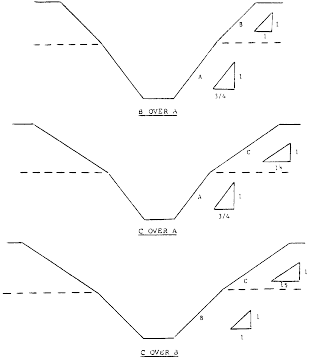
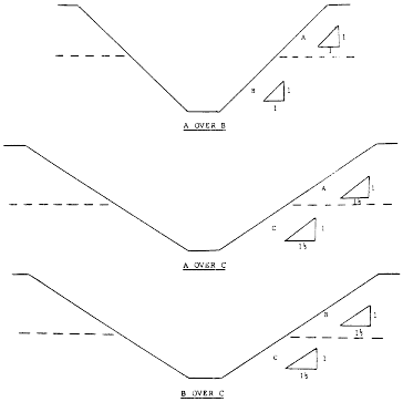
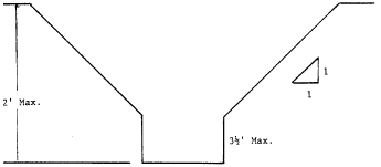
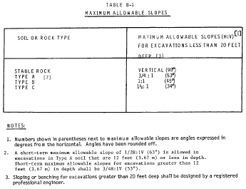 Figure
B-1 Slope Configurations
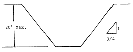 Simple
Slope - General
 Simple
Slope - Short Term
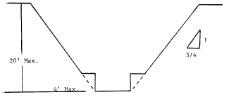 Simple
Bench
 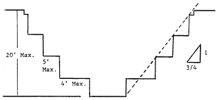 Multiple Bench
 Unsupported Vertically Sided Lower Portion - Maximum 8 Feet in
Depth
 Unsupported Vertically Sided Lower Portion - Maximum 12 Feet in
Depth
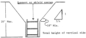 Supported
or Shielded Vertically Sided Lower Portion
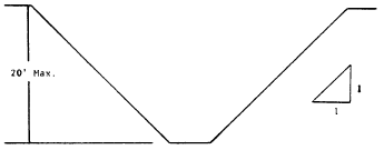 Simple
Slope
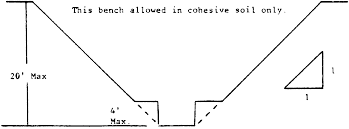 Single
Bench
 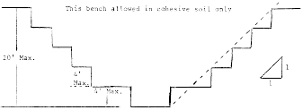 Multiple Bench
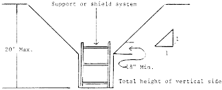 Vertically Sided Lower Portion
 Simple
Slope
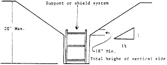 Vertical
Sided Lower Portion
