Title 14
PART 25 APPENDIX
| Position | BTU's/ft 2sec | Watts/cm 2 |
|---|---|---|
| “Zero” Position | 1.5 | 1.7 |
| Position 1 | 1.51-1.50-1.49 | 1.71-1.70-1.69 |
| Position 2 | 1.43-1.44 | 1.62-1.63 |
(4) Open the bottom door, remove the calorimeter and holder fixture. Use caution as the fixture is very hot.
(f) Test Procedure. (1) Ignite the pilot burner. Ensure that it is at least 2 inches (51 mm) above the top of the platform. The burner must not contact the specimen until the test begins.
(2) Place the test specimen in the sliding platform holder. Ensure that the test sample surface is level with the top of the platform. At “zero” point, the specimen surface must be 7 1/2 inches ± 1/8 inch (191 mm ±3) below the radiant panel.
(3) Place the retaining/securing frame over the test specimen. It may be necessary (due to compression) to adjust the sample (up or down) in order to maintain the distance from the sample to the radiant panel (7 1/2 inches ± 1/8 inch (191 mm±3) at “zero” position). With film/fiberglass assemblies, it is critical to make a slit in the film cover to purge any air inside. This allows the operator to maintain the proper test specimen position (level with the top of the platform) and to allow ventilation of gases during testing. A longitudinal slit, approximately 2 inches (51mm) in length, must be centered 3 inches ± 1/2 inch (76mm±13mm) from the left flange of the securing frame. A utility knife is acceptable for slitting the film cover.
(4) Immediately push the sliding platform into the chamber and close the bottom door.
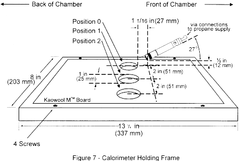
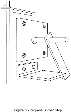
(5) Bring the pilot burner flame into contact with the center of the specimen at the “zero” point and simultaneously start the timer. The pilot burner must be at a 27° angle with the sample and be approximately 1/2 inch (12 mm) above the sample. See figure 7. A stop, as shown in figure 8, allows the operator to position the burner correctly each time.
(6) Leave the burner in position for 15 seconds and then remove to a position at least 2 inches (51 mm) above the specimen.
(g) Report. (1) Identify and describe the test specimen.
(2) Report any shrinkage or melting of the test specimen.
(3) Report the flame propagation distance. If this distance is less than 2 inches, report this as a pass (no measurement required).
(4) Report the after-flame time.
(h) Requirements. (1) There must be no flame propagation beyond 2 inches (51 mm) to the left of the centerline of the pilot flame application.
(2) The flame time after removal of the pilot burner may not exceed 3 seconds on any specimen.
Part VII - Test Method To Determine the Burnthrough Resistance of Thermal/Acoustic Insulation MaterialsUse the following test method to evaluate the burnthrough resistance characteristics of aircraft thermal/acoustic insulation materials when exposed to a high intensity open flame.
(a) Definitions.
Burnthrough time means the time, in seconds, for the burner flame to penetrate the test specimen, and/or the time required for the heat flux to reach 2.0 Btu/ft 2sec (2.27 W/cm 2) on the inboard side, at a distance of 12 inches (30.5 cm) from the front surface of the insulation blanket test frame, whichever is sooner. The burnthrough time is measured at the inboard side of each of the insulation blanket specimens.
Insulation blanket specimen means one of two specimens positioned in either side of the test rig, at an angle of 30° with respect to vertical.
Specimen set means two insulation blanket specimens. Both specimens must represent the same production insulation blanket construction and materials, proportioned to correspond to the specimen size.
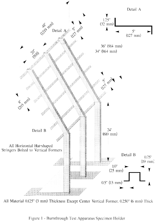
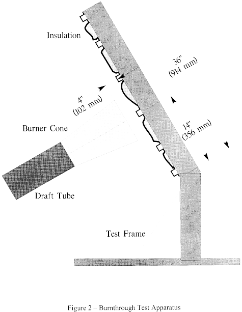
(b) Apparatus. (1) The arrangement of the test apparatus is shown in figures 1 and 2 and must include the capability of swinging the burner away from the test specimen during warm-up.
(2) Test burner. The test burner must be a modified gun-type such as the Park Model DPL 3400. Flame characteristics are highly dependent on actual burner setup. Parameters such as fuel pressure, nozzle depth, stator position, and intake airflow must be properly adjusted to achieve the correct flame output.
(i) Nozzle. A nozzle must maintain the fuel pressure to yield a nominal 6.0 gal/hr (0.378 L/min) fuel flow. A Monarch-manufactured 80° PL (hollow cone) nozzle nominally rated at 6.0 gal/hr at 100 lb/in 2 (0.71 MPa) delivers a proper spray pattern.
(ii) Fuel Rail. The fuel rail must be adjusted to position the fuel nozzle at a depth of 0.3125 inch (8 mm) from the end plane of the exit stator, which must be mounted in the end of the draft tube.
(iii) Internal Stator. The internal stator, located in the middle of the draft tube, must be positioned at a depth of 3.75 inches (95 mm) from the tip of the fuel nozzle. The stator must also be positioned such that the integral igniters are located at an angle midway between the 10 and 11 o'clock position, when viewed looking into the draft tube. Minor deviations to the igniter angle are acceptable if the temperature and heat flux requirements conform to the requirements of paragraph VII(e) of this appendix.
(iv) Blower Fan. The cylindrical blower fan used to pump air through the burner must measure 5.25 inches (133 mm) in diameter by 3.5 inches (89 mm) in width.
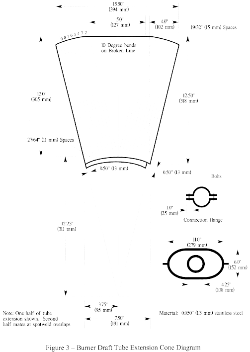
(v) Burner cone. Install a 12 + 0.125-inch (305 ±3 mm) burner extension cone at the end of the draft tube. The cone must have an opening 6 ±0.125-inch (152 ±3 mm) high and 11 ±0.125-inch (280 ±3 mm) wide (see figure 3).
(vi) Fuel. Use JP-8, Jet A, or their international equivalent, at a flow rate of 6.0 ±0.2 gal/hr (0.378 ±0.0126 L/min). If this fuel is unavailable, ASTM K2 fuel (Number 2 grade kerosene) or ASTM D2 fuel (Number 2 grade fuel oil or Number 2 diesel fuel) are acceptable if the nominal fuel flow rate, temperature, and heat flux measurements conform to the requirements of paragraph VII(e) of this appendix.
(vii) Fuel pressure regulator. Provide a fuel pressure regulator, adjusted to deliver a nominal 6.0 gal/hr (0.378 L/min) flow rate. An operating fuel pressure of 100 lb/in 2 (0.71 MPa) for a nominally rated 6.0 gal/hr 80° spray angle nozzle (such as a PL type) delivers 6.0 ±0.2 gal/hr (0.378 ±0.0126 L/min).
(3) Calibration rig and equipment. (i) Construct individual calibration rigs to incorporate a calorimeter and thermocouple rake for the measurement of heat flux and temperature. Position the calibration rigs to allow movement of the burner from the test rig position to either the heat flux or temperature position with minimal difficulty.
(ii) Calorimeter. The calorimeter must be a total heat flux, foil type Gardon Gage of an appropriate range such as 0-20 Btu/ft 2-sec (0-22.7 W/cm 2), accurate to ±3% of the indicated reading. The heat flux calibration method must be in accordance with paragraph VI(b)(7) of this appendix.
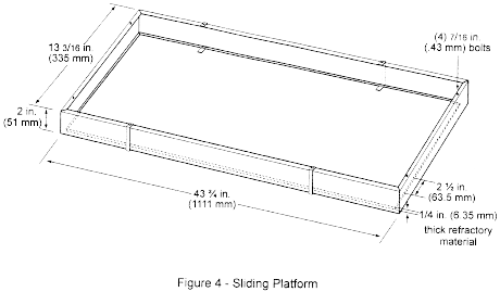
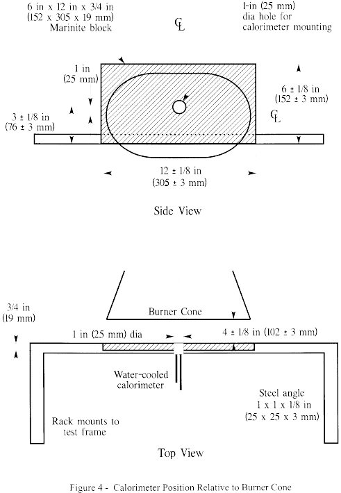
(iii) Calorimeter mounting. Mount the calorimeter in a 6- by 12- ±0.125 inch (152- by 305- ±3 mm) by 0.75 ±0.125 inch (19 mm ±3 mm) thick insulating block which is attached to the heat flux calibration rig during calibration (figure 4). Monitor the insulating block for deterioration and replace it when necessary. Adjust the mounting as necessary to ensure that the calorimeter face is parallel to the exit plane of the test burner cone.
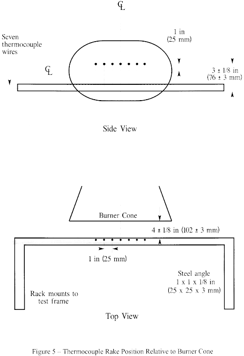
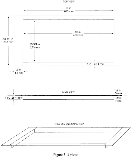
(iv) Thermocouples. Provide seven 1/8-inch (3.2 mm) ceramic packed, metal sheathed, type K (Chromel-alumel), grounded junction thermocouples with a nominal 24 American Wire Gauge (AWG) size conductor for calibration. Attach the thermocouples to a steel angle bracket to form a thermocouple rake for placement in the calibration rig during burner calibration (figure 5).
(v) Air velocity meter. Use a vane-type air velocity meter to calibrate the velocity of air entering the burner. An Omega Engineering Model HH30A is satisfactory. Use a suitable adapter to attach the measuring device to the inlet side of the burner to prevent air from entering the burner other than through the measuring device, which would produce erroneously low readings. Use a flexible duct, measuring 4 inches wide (102 mm) by 20 feet long (6.1 meters), to supply fresh air to the burner intake to prevent damage to the air velocity meter from ingested soot. An optional airbox permanently mounted to the burner intake area can effectively house the air velocity meter and provide a mounting port for the flexible intake duct.
(4) Test specimen mounting frame. Make the mounting frame for the test specimens of 1/8-inch (3.2 mm) thick steel as shown in figure 1, except for the center vertical former, which should be 1/4-inch (6.4 mm) thick to minimize warpage. The specimen mounting frame stringers (horizontal) should be bolted to the test frame formers (vertical) such that the expansion of the stringers will not cause the entire structure to warp. Use the mounting frame for mounting the two insulation blanket test specimens as shown in figure 2.
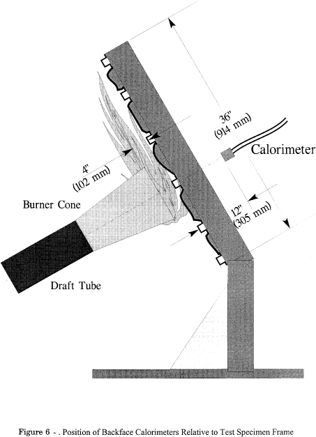
(5) Backface calorimeters. Mount two total heat flux Gardon type calorimeters behind the insulation test specimens on the back side (cold) area of the test specimen mounting frame as shown in figure 6. Position the calorimeters along the same plane as the burner cone centerline, at a distance of 4 inches (102 mm) from the vertical centerline of the test frame.
(i) The calorimeters must be a total heat flux, foil type Gardon Gage of an appropriate range such as 0-5 Btu/ft 2-sec (0-5.7 W/cm 2), accurate to ±3% of the indicated reading. The heat flux calibration method must comply with paragraph VI(b)(7) of this appendix.
(6) Instrumentation. Provide a recording potentiometer or other suitable calibrated instrument with an appropriate range to measure and record the outputs of the calorimeter and the thermocouples.
(7) Timing device. Provide a stopwatch or other device, accurate to ±1%, to measure the time of application of the burner flame and burnthrough time.
(8) Test chamber. Perform tests in a suitable chamber to reduce or eliminate the possibility of test fluctuation due to air movement. The chamber must have a minimum floor area of 10 by 10 feet (305 by 305 cm).
(i) Ventilation hood. Provide the test chamber with an exhaust system capable of removing the products of combustion expelled during tests.
(c) Test Specimens. (1) Specimen preparation. Prepare a minimum of three specimen sets of the same construction and configuration for testing.
(2) Insulation blanket test specimen.
(i) For batt-type materials such as fiberglass, the constructed, finished blanket specimen assemblies must be 32 inches wide by 36 inches long (81.3 by 91.4 cm), exclusive of heat sealed film edges.
(ii) For rigid and other non-conforming types of insulation materials, the finished test specimens must fit into the test rig in such a manner as to replicate the actual in-service installation.
(3) Construction. Make each of the specimens tested using the principal components (i.e., insulation, fire barrier material if used, and moisture barrier film) and assembly processes (representative seams and closures).
(i) Fire barrier material. If the insulation blanket is constructed with a fire barrier material, place the fire barrier material in a manner reflective of the installed arrangement For example, if the material will be placed on the outboard side of the insulation material, inside the moisture film, place it the same way in the test specimen.
(ii) Insulation material. Blankets that utilize more than one variety of insulation (composition, density, etc.) must have specimen sets constructed that reflect the insulation combination used. If, however, several blanket types use similar insulation combinations, it is not necessary to test each combination if it is possible to bracket the various combinations.
(iii) Moisture barrier film. If a production blanket construction utilizes more than one type of moisture barrier film, perform separate tests on each combination. For example, if a polyimide film is used in conjunction with an insulation in order to enhance the burnthrough capabilities, also test the same insulation when used with a polyvinyl fluoride film.
(iv) Installation on test frame. Attach the blanket test specimens to the test frame using 12 steel spring type clamps as shown in figure 7. Use the clamps to hold the blankets in place in both of the outer vertical formers, as well as the center vertical former (4 clamps per former). The clamp surfaces should measure 1 inch by 2 inches (25 by 51 mm). Place the top and bottom clamps 6 inches (15.2 cm) from the top and bottom of the test frame, respectively. Place the middle clamps 8 inches (20.3 cm) from the top and bottom clamps.
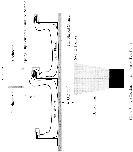
(Note: For blanket materials that cannot be installed in accordance with figure 7 above, the blankets must be installed in a manner approved by the FAA.)
(v) Conditioning. Condition the specimens at 70° ±5 °F (21° ±2 °C) and 55% ±10% relative humidity for a minimum of 24 hours prior to testing.
(d) Preparation of apparatus. (1) Level and center the frame assembly to ensure alignment of the calorimeter and/or thermocouple rake with the burner cone.
(2) Turn on the ventilation hood for the test chamber. Do not turn on the burner blower. Measure the airflow of the test chamber using a vane anemometer or equivalent measuring device. The vertical air velocity just behind the top of the upper insulation blanket test specimen must be 100 ±50 ft/min (0.51 ±0.25 m/s). The horizontal air velocity at this point must be less than 50 ft/min (0.25 m/s).
(3) If a calibrated flow meter is not available, measure the fuel flow rate using a graduated cylinder of appropriate size. Turn on the burner motor/fuel pump, after insuring that the igniter system is turned off. Collect the fuel via a plastic or rubber tube into the graduated cylinder for a 2-minute period. Determine the flow rate in gallons per hour. The fuel flow rate must be 6.0 ±0.2 gallons per hour (0.378 ±0.0126 L/min).
(e) Calibration. (1) Position the burner in front of the calorimeter so that it is centered and the vertical plane of the burner cone exit is 4 ±0.125 inches (102 ±3 mm) from the calorimeter face. Ensure that the horizontal centerline of the burner cone is offset 1 inch below the horizontal centerline of the calorimeter (figure 8). Without disturbing the calorimeter position, rotate the burner in front of the thermocouple rake, such that the middle thermocouple (number 4 of 7) is centered on the burner cone.
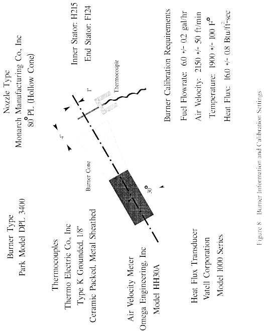
Ensure that the horizontal centerline of the burner cone is also offset 1 inch below the horizontal centerline of the thermocouple tips. Re-check measurements by rotating the burner to each position to ensure proper alignment between the cone and the calorimeter and thermocouple rake. (Note: The test burner mounting system must incorporate “detents” that ensure proper centering of the burner cone with respect to both the calorimeter and the thermocouple rakes, so that rapid positioning of the burner can be achieved during the calibration procedure.)
(2) Position the air velocity meter in the adapter or airbox, making certain that no gaps exist where air could leak around the air velocity measuring device. Turn on the blower/motor while ensuring that the fuel solenoid and igniters are off. Adjust the air intake velocity to a level of 2150 ft/min, (10.92 m/s) then turn off the blower/motor. (Note: The Omega HH30 air velocity meter measures 2.625 inches in diameter. To calculate the intake airflow, multiply the cross-sectional area (0.03758 ft 2) by the air velocity (2150 ft/min) to obtain 80.80 ft 3/min. An air velocity meter other than the HH30 unit can be used, provided the calculated airflow of 80.80 ft 3/min (2.29 m 3/min) is equivalent.)
(3) Rotate the burner from the test position to the warm-up position. Prior to lighting the burner, ensure that the calorimeter face is clean of soot deposits, and there is water running through the calorimeter. Examine and clean the burner cone of any evidence of buildup of products of combustion, soot, etc. Soot buildup inside the burner cone may affect the flame characteristics and cause calibration difficulties. Since the burner cone may distort with time, dimensions should be checked periodically.
(4) While the burner is still rotated to the warm-up position, turn on the blower/motor, igniters and fuel flow, and light the burner. Allow it to warm up for a period of 2 minutes. Move the burner into the calibration position and allow 1 minute for calorimeter stabilization, then record the heat flux once every second for a period of 30 seconds. Turn off burner, rotate out of position, and allow to cool. Calculate the average heat flux over this 30-second duration. The average heat flux should be 16.0 ±0.8 Btu/ft 2 sec (18.2 ±0.9 W/cm 2).
(5) Position the burner in front of the thermocouple rake. After checking for proper alignment, rotate the burner to the warm-up position, turn on the blower/motor, igniters and fuel flow, and light the burner. Allow it to warm up for a period of 2 minutes. Move the burner into the calibration position and allow 1 minute for thermocouple stabilization, then record the temperature of each of the 7 thermocouples once every second for a period of 30 seconds. Turn off burner, rotate out of position, and allow to cool. Calculate the average temperature of each thermocouple over this 30-second period and record. The average temperature of each of the 7 thermocouples should be 1900 °F ±100 °F (1038 ±56 °C).
(6) If either the heat flux or the temperatures are not within the specified range, adjust the burner intake air velocity and repeat the procedures of paragraphs (4) and (5) above to obtain the proper values. Ensure that the inlet air velocity is within the range of 2150 ft/min ±50 ft/min (10.92 ±0.25 m/s).
(7) Calibrate prior to each test until consistency has been demonstrated. After consistency has been confirmed, several tests may be conducted with calibration conducted before and after a series of tests.
(f) Test procedure. (1) Secure the two insulation blanket test specimens to the test frame. The insulation blankets should be attached to the test rig center vertical former using four spring clamps positioned as shown in figure 7 (according to the criteria of paragraph paragraph (c)(3)(iv) of this part of this appendix).
(2) Ensure that the vertical plane of the burner cone is at a distance of 4 ±0.125 inch (102 ±3 mm) from the outer surface of the horizontal stringers of the test specimen frame, and that the burner and test frame are both situated at a 30° angle with respect to vertical.
(3) When ready to begin the test, direct the burner away from the test position to the warm-up position so that the flame will not impinge on the specimens prematurely. Turn on and light the burner and allow it to stabilize for 2 minutes.
(4) To begin the test, rotate the burner into the test position and simultaneously start the timing device.
(5) Expose the test specimens to the burner flame for 4 minutes and then turn off the burner. Immediately rotate the burner out of the test position.
(6) Determine (where applicable) the burnthrough time, or the point at which the heat flux exceeds 2.0 Btu/ft 2-sec (2.27 W/cm 2).
(g) Report. (1) Identify and describe the specimen being tested.
(2) Report the number of insulation blanket specimens tested.
(3) Report the burnthrough time (if any), and the maximum heat flux on the back face of the insulation blanket test specimen, and the time at which the maximum occurred.
(h) Requirements. (1) Each of the two insulation blanket test specimens must not allow fire or flame penetration in less than 4 minutes.
(2) Each of the two insulation blanket test specimens must not allow more than 2.0 Btu/ft 2-sec (2.27 W/cm 2) on the cold side of the insulation specimens at a point 12 inches (30.5 cm) from the face of the test rig.
[Amdt. 25-32, 37 FR 3972, Feb. 24, 1972] Editorial Note:For Federal Register citations affecting appendix F to Part 25, see the List of CFR Sections Affected, which appears in the Finding Aids section of the printed volume and at www.govinfo.gov.Appendix H to Part 25 - Instructions for Continued Airworthiness
14:1.0.1.3.12.12.121.1.13 : Appendix H
Appendix H to Part 25 - Instructions for Continued Airworthiness H25.1 General.(a) This appendix specifies requirements for preparation of Instructions for Continued Airworthiness as required by §§ 25.1529, 25.1729, and applicable provisions of parts 21 and 26 of this chapter.
(b) The Instructions for Continued Airworthiness for each airplane must include the Instructions for Continued Airworthiness for each engine and propeller (hereinafter designated “products”), for each appliance required by this chapter, and any required information relating to the interface of those appliances and products with the airplane. If Instructions for Continued Airworthiness are not supplied by the manufacturer of an appliance or product installed in the airplane, the Instructions for Continued Airworthiness for the airplane must include the information essential to the continued airworthiness of the airplane.
(c) The applicant must submit to the FAA a program to show how changes to the Instructions for Continued Airworthiness made by the applicant or by the manufacturers or products and appliances installed in the airplane will be distributed.
H25.2 Format.(a) The Instructions for Continued Airworthiness must be in the form of a manual or manuals as appropriate for the quantity of data to be provided.
(b) The format of the manual or manuals must provide for a practical arrangement.
H25.3 Content.The contents of the manual or manuals must be prepared in the English language. The Instructions for Continued Airworthiness must contain the following manuals or sections, as appropriate, and information:
(a) Airplane maintenance manual or section. (1) Introduction information that includes an explanation of the airplane's features and data to the extent necessary for maintenance or preventive maintenance.
(2) A description of the airplane and its systems and installations including its engines, propellers, and appliances.
(3) Basic control and operation information describing how the airplane components and systems are controlled and how they operate, including any special procedures and limitations that apply.
(4) Servicing information that covers details regarding servicing points, capacities of tanks, reservoirs, types of fluids to be used, pressures applicable to the various systems, location of access panels for inspection and servicing, locations of lubrication points, lubricants to be used, equipment required for servicing, tow instructions and limitations, mooring, jacking, and leveling information.
(b) Maintenance instructions. (1) Scheduling information for each part of the airplane and its engines, auxiliary power units, propellers, accessories, instruments, and equipment that provides the recommended periods at which they should be cleaned, inspected, adjusted, tested, and lubricated, and the degree of inspection, the applicable wear tolerances, and work recommended at these periods. However, the applicant may refer to an accessory, instrument, or equipment manufacturer as the source of this information if the applicant shows that the item has an exceptionally high degree of complexity requiring specialized maintenance techniques, test equipment, or expertise. The recommended overhaul periods and necessary cross references to the Airworthiness Limitations section of the manual must also be included. In addition, the applicant must include an inspection program that includes the frequency and extent of the inspections necessary to provide for the continued airworthiness of the airplane.
(2) Troubleshooting information describing probable malfunctions, how to recognize those malfunctions, and the remedial action for those malfunctions.
(3) Information describing the order and method of removing and replacing products and parts with any necessary precautions to be taken.
(4) Other general procedural instructions including procedures for system testing during ground running, symmetry checks, weighing and determining the center of gravity, lifting and shoring, and storage limitations.
(c) Diagrams of structural access plates and information needed to gain access for inspections when access plates are not provided.
(d) Details for the application of special inspection techniques including radiographic and ultrasonic testing where such processes are specified.
(e) Information needed to apply protective treatments to the structure after inspection.
(f) All data relative to structural fasteners such as identification, discard recommendations, and torque values.
(g) A list of special tools needed.
H25.4 Airworthiness Limitations section.(a) The Instructions for Continued Airworthiness must contain a section titled Airworthiness Limitations that is segregated and clearly distinguishable from the rest of the document. This section must set forth -
(1) Each mandatory modification time, replacement time, structural inspection interval, and related structural inspection procedure approved under § 25.571.
(2) Each mandatory replacement time, inspection interval, related inspection procedure, and all critical design configuration control limitations approved under § 25.981 for the fuel tank system.
(3) Any mandatory replacement time of EWIS components as defined in section 25.1701.
(4) A limit of validity of the engineering data that supports the structural maintenance program (LOV), stated as a total number of accumulated flight cycles or flight hours or both, approved under § 25.571. Until the full-scale fatigue testing is completed and the FAA has approved the LOV, the number of cycles accumulated by the airplane cannot be greater than 1/2 the number of cycles accumulated on the fatigue test article.
(5) Each mandatory replacement time, inspection interval, and related inspection and test procedure, and each critical design configuration control limitation for each lightning protection feature approved under § 25.954.
(b) If the Instructions for Continued Airworthiness consist of multiple documents, the section required by this paragraph must be included in the principal manual. This section must contain a legible statement in a prominent location that reads: “The Airworthiness Limitations section is FAA-approved and specifies maintenance required under §§ 43.16 and 91.403 of the Federal Aviation Regulations, unless an alternative program has been FAA approved.”
H25.5 Electrical Wiring Interconnection System (EWIS) Instructions for Continued Airworthiness.
(a) The applicant must prepare Instructions for Continued Airworthiness (ICA) applicable to EWIS as defined by § 25.1701 that are approved by the FAA and include the following:
(1) Maintenance and inspection requirements for the EWIS developed with the use of an enhanced zonal analysis procedure that includes:
(i) Identification of each zone of the airplane.
(ii) Identification of each zone that contains EWIS.
(iii) Identification of each zone containing EWIS that also contains combustible materials.
(iv) Identification of each zone in which EWIS is in close proximity to both primary and back-up hydraulic, mechanical, or electrical flight controls and lines.
(v) Identification of -
(A) Tasks, and the intervals for performing those tasks, that will reduce the likelihood of ignition sources and accumulation of combustible material, and
(B) Procedures, and the intervals for performing those procedures, that will effectively clean the EWIS components of combustible material if there is not an effective task to reduce the likelihood of combustible material accumulation.
(vi) Instructions for protections and caution information that will minimize contamination and accidental damage to EWIS, as applicable, during performance of maintenance, alteration, or repairs.
(2) Acceptable EWIS maintenance practices in a standard format.
(3) Wire separation requirements as determined under § 25.1707.
(4) Information explaining the EWIS identification method and requirements for identifying any changes to EWIS under § 25.1711.
(5) Electrical load data and instructions for updating that data.
(b) The EWIS ICA developed in accordance with the requirements of H25.5(a)(1) must be in the form of a document appropriate for the information to be provided, and they must be easily recognizable as EWIS ICA. This document must either contain the required EWIS ICA or specifically reference other portions of the ICA that contain this information.
[Amdt. 25-54, 45 FR 60177, Sept. 11, 1980, as amended by Amdt. 25-68, 54 FR 34329, Aug. 18, 1989; Amdt. 25-102, 66 FR 23130, May 7, 2001; Amdt. 25-123, 72 FR 63408, Nov. 8, 2007; Amdt. 25-132, 75 FR 69782, Nov. 15, 2010; Doc. No. FAA-2014-1027, Amdt. No. 25-146, 83 FR 47557, Sept. 20, 2018]Appendix I to Part 25 - Installation of an Automatic Takeoff Thrust Control System (ATTCS)
14:1.0.1.3.12.12.121.1.14 : Appendix I
Appendix I to Part 25 - Installation of an Automatic Takeoff Thrust Control System (ATTCS) I25.1 General.(a) This appendix specifies additional requirements for installation of an engine power control system that automatically resets thrust or power on operating engine(s) in the event of any one engine failure during takeoff.
(b) With the ATTCS and associated systems functioning normally as designed, all applicable requirements of Part 25, except as provided in this appendix, must be met without requiring any action by the crew to increase thrust or power.
I25.2 Definitions.(a) Automatic Takeoff Thrust Control System (ATTCS). An ATTCS is defined as the entire automatic system used on takeoff, including all devices, both mechanical and electrical, that sense engine failure, transmit signals, actuate fuel controls or power levers or increase engine power by other means on operating engines to achieve scheduled thrust or power increases, and furnish cockpit information on system operation.
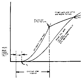
(b) Critical Time Interval. When conducting an ATTCS takeoff, the critical time interval is between V1 minus 1 second and a point on the minimum performance, all-engine flight path where, assuming a simultaneous occurrence of an engine and ATTCS failure, the resulting minimum flight path thereafter intersects the Part 25 required actual flight path at no less than 400 feet above the takeoff surface. This time interval is shown in the following illustration:
 I25.3
Performance and System Reliability Requirements.
The applicant must comply with the performance and ATTCS reliability requirements as follows:
(a) An ATTCS failure or a combination of failures in the ATTCS during the critical time interval:
(1) Shall not prevent the insertion of the maximum approved takeoff thrust or power, or must be shown to be an improbable event.
(2) Shall not result in a significant loss or reduction in thrust or power, or must be shown to be an extremely improbable event.
(b) The concurrent existence of an ATTCS failure and an engine failure during the critical time interval must be shown to be extremely improbable.
(c) All applicable performance requirements of Part 25 must be met with an engine failure occurring at the most critical point during takeoff with the ATTCS system functioning.
I25.4 Thrust Setting.The initial takeoff thrust or power setting on each engine at the beginning of the takeoff roll may not be less than any of the following:
(a) Ninety (90) percent of the thrust or power set by the ATTCS (the maximum takeoff thrust or power approved for the airplane under existing ambient conditions);
(b) That required to permit normal operation of all safety-related systems and equipment dependent upon engine thrust or power lever position; or
(c) That shown to be free of hazardous engine response characteristics when thrust or power is advanced from the initial takeoff thrust or power to the maximum approved takeoff thrust or power.
I25.5 Powerplant Controls.(a) In addition to the requirements of § 25.1141, no single failure or malfunction, or probable combination thereof, of the ATTCS, including associated systems, may cause the failure of any powerplant function necessary for safety.
(b) The ATTCS must be designed to:
(1) Apply thrust or power on the operating engine(s), following any one engine failure during takeoff, to achieve the maximum approved takeoff thrust or power without exceeding engine operating limits;
(2) Permit manual decrease or increase in thrust or power up to the maximum takeoff thrust or power approved for the airplane under existing conditions through the use of the power lever. For airplanes equipped with limiters that automatically prevent engine operating limits from being exceeded under existing ambient conditions, other means may be used to increase the thrust or power in the event of an ATTCS failure provided the means is located on or forward of the power levers; is easily identified and operated under all operating conditions by a single action of either pilot with the hand that is normally used to actuate the power levers; and meets the requirements of § 25.777 (a), (b), and (c);
(3) Provide a means to verify to the flightcrew before takeoff that the ATTCS is in a condition to operate; and
(4) Provide a means for the flightcrew to deactivate the automatic function. This means must be designed to prevent inadvertent deactivation.
I25.6 Powerplant Instruments.In addition to the requirements of § 25.1305:
(a) A means must be provided to indicate when the ATTCS is in the armed or ready condition; and
(b) If the inherent flight characteristics of the airplane do not provide adequate warning that an engine has failed, a warning system that is independent of the ATTCS must be provided to give the pilot a clear warning of any engine failure during takeoff.
[Amdt. 25-62, 52 FR 43156, Nov. 9, 1987]Appendix J to Part 25 - Emergency Evacuation
14:1.0.1.3.12.12.121.1.15 : Appendix J
Appendix J to Part 25 - Emergency EvacuationThe following test criteria and procedures must be used for showing compliance with § 25.803:
(a) The emergency evacuation must be conducted with exterior ambient light levels of no greater than 0.3 foot-candles prior to the activation of the airplane emergency lighting system. The source(s) of the initial exterior ambient light level may remain active or illuminated during the actual demonstration. There must, however, be no increase in the exterior ambient light level except for that due to activation of the airplane emergency lighting system.
(b) The airplane must be in a normal attitude with landing gear extended.
(c) Unless the airplane is equipped with an off-wing descent means, stands or ramps may be used for descent from the wing to the ground. Safety equipment such as mats or inverted life rafts may be placed on the floor or ground to protect participants. No other equipment that is not part of the emergency evacuation equipment of the airplane may be used to aid the participants in reaching the ground.
(d) Except as provided in paragraph (a) of this appendix, only the airplane's emergency lighting system may provide illumination.
(e) All emergency equipment required for the planned operation of the airplane must be installed.
(f) Each internal door or curtain must be in the takeoff configuration.
(g) Each crewmember must be seated in the normally assigned seat for takeoff and must remain in the seat until receiving the signal for commencement of the demonstration. Each crewmember must be a person having knowledge of the operation of exits and emergency equipment and, if compliance with § 121.291 is also being demonstrated, each flight attendant must be a member of a regularly scheduled line crew.
(h) A representative passenger load of persons in normal health must be used as follows:
(1) At least 40 percent of the passenger load must be female.
(2) At least 35 percent of the passenger load must be over 50 years of age.
(3) At least 15 percent of the passenger load must be female and over 50 years of age.
(4) Three life-size dolls, not included as part of the total passenger load, must be carried by passengers to simulate live infants 2 years old or younger.
(5) Crewmembers, mechanics, and training personnel, who maintain or operate the airplane in the normal course of their duties, may not be used as passengers.
(i) No passenger may be assigned a specific seat except as the Administrator may require. Except as required by subparagraph (g) of this paragraph, no employee of the applicant may be seated next to an emergency exit.
(j) Seat belts and shoulder harnesses (as required) must be fastened.
(k) Before the start of the demonstration, approximately one-half of the total average amount of carry-on baggage, blankets, pillows, and other similar articles must be distributed at several locations in aisles and emergency exit access ways to create minor obstructions.
(l) No prior indication may be given to any crewmember or passenger of the particular exits to be used in the demonstration.
(m) The applicant may not practice, rehearse, or describe the demonstration for the participants nor may any participant have taken part in this type of demonstration within the preceding 6 months.
(n) Prior to entering the demonstration aircraft, the passengers may also be advised to follow directions of crewmembers but may not be instructed on the procedures to be followed in the demonstration, except with respect to safety procedures in place for the demonstration or which have to do with the demonstration site. Prior to the start of the demonstration, the pre-takeoff passenger briefing required by § 121.571 may be given. Flight attendants may assign demonstration subjects to assist persons from the bottom of a slide, consistent with their approved training program.
(o) The airplane must be configured to prevent disclosure of the active emergency exits to demonstration participants in the airplane until the start of the demonstration.
(p) Exits used in the demonstration must consist of one exit from each exit pair. The demonstration may be conducted with the escape slides, if provided, inflated and the exits open at the beginning of the demonstration. In this case, all exits must be configured such that the active exits are not disclosed to the occupants. If this method is used, the exit preparation time for each exit utilized must be accounted for, and exits that are not to be used in the demonstration must not be indicated before the demonstration has started. The exits to be used must be representative of all of the emergency exits on the airplane and must be designated by the applicant, subject to approval by the Administrator. At least one floor level exit must be used.
(q) Except as provided in paragraph (c) of this section, all evacuees must leave the airplane by a means provided as part of the airplane's equipment.
(r) The applicant's approved procedures must be fully utilized, except the flightcrew must take no active role in assisting others inside the cabin during the demonstration.
(s) The evacuation time period is completed when the last occupant has evacuated the airplane and is on the ground. Provided that the acceptance rate of the stand or ramp is no greater than the acceptance rate of the means available on the airplane for descent from the wing during an actual crash situation, evacuees using stands or ramps allowed by paragraph (c) of this appendix are considered to be on the ground when they are on the stand or ramp.
[Amdt. 25-72, 55 FR 29788, July 20, 1990, as amended by Amdt. 25-79, Aug. 26, 1993; Amdt. 25-117, 69 FR 67499, Nov. 17, 2004]Appendix K to Part 25 - Extended Operations (ETOPS)
14:1.0.1.3.12.12.121.1.16 : Appendix K
Appendix K to Part 25 - Extended Operations (ETOPS)This appendix specifies airworthiness requirements for the approval of an airplane-engine combination for extended operations (ETOPS). For two-engine airplanes, the applicant must comply with sections K25.1 and K25.2 of this appendix. For airplanes with more than two engines, the applicant must comply with sections K25.1 and K25.3 of this appendix.
K25.1 Design requirements.
K25.1.1 Part 25 compliance.
The airplane-engine combination must comply with the requirements of part 25 considering the maximum flight time and the longest diversion time for which the applicant seeks approval.
K25.1.2 Human factors.
An applicant must consider crew workload, operational implications, and the crew's and passengers' physiological needs during continued operation with failure effects for the longest diversion time for which it seeks approval.
K25.1.3 Airplane systems.
(a) Operation in icing conditions.
(1) The airplane must be certificated for operation in icing conditions in accordance with § 25.1419.
(2) The airplane must be able to safely conduct an ETOPS diversion with the most critical ice accretion resulting from:
(i) Icing conditions encountered at an altitude that the airplane would have to fly following an engine failure or cabin decompression.
(ii) A 15-minute hold in the continuous maximum icing conditions specified in Appendix C of this part with a liquid water content factor of 1.0.
(iii) Ice accumulated during approach and landing in the icing conditions specified in Appendix C of this part.
(b) Electrical power supply. The airplane must be equipped with at least three independent sources of electrical power.
(c) Time limited systems. The applicant must define the system time capability of each ETOPS significant system that is time-limited.
K25.1.4 Propulsion systems.
(a) Fuel system design. Fuel necessary to complete an ETOPS flight (including a diversion for the longest time for which the applicant seeks approval) must be available to the operating engines at the pressure and fuel-flow required by § 25.955 under any airplane failure condition not shown to be extremely improbable. Types of failures that must be considered include, but are not limited to: crossfeed valve failures, automatic fuel management system failures, and normal electrical power generation failures.
(1) If the engine has been certified for limited operation with negative engine-fuel-pump-inlet pressures, the following requirements apply:
(i) Airplane demonstration-testing must cover worst case cruise and diversion conditions involving:
(A) Fuel grade and temperature.
(B) Thrust or power variations.
(C) Turbulence and negative G.
(D) Fuel system components degraded within their approved maintenance limits.
(ii) Unusable-fuel quantity in the suction feed configuration must be determined in accordance with § 25.959.
(2) For two-engine airplanes to be certificated for ETOPS beyond 180 minutes, one fuel boost pump in each main tank and at least one crossfeed valve, or other means for transferring fuel, must be powered by an independent electrical power source other than the three power sources required to comply with section K25.1.3(b) of this appendix. This requirement does not apply if the normal fuel boost pressure, crossfeed valve actuation, or fuel transfer capability is not provided by electrical power.
(3) An alert must be displayed to the flightcrew when the quantity of fuel available to the engines falls below the level required to fly to the destination. The alert must be given when there is enough fuel remaining to safely complete a diversion. This alert must account for abnormal fuel management or transfer between tanks, and possible loss of fuel. This paragraph does not apply to airplanes with a required flight engineer.
(b) APU design. If an APU is needed to comply with this appendix, the applicant must demonstrate that:
(1) The reliability of the APU is adequate to meet those requirements; and
(2) If it is necessary that the APU be able to start in flight, it is able to start at any altitude up to the maximum operating altitude of the airplane, or 45,000 feet, whichever is lower, and run for the remainder of any flight .
(c) Engine oil tank design. The engine oil tank filler cap must comply with § 33.71(c)(4) of this chapter.
K25.1.5 Engine-condition monitoring.
Procedures for engine-condition monitoring must be specified and validated in accordance with Part 33, Appendix A, paragraph A33.3(c) of this chapter.
K25.1.6 Configuration, maintenance, and procedures.
The applicant must list any configuration, operating and maintenance requirements, hardware life limits, MMEL constraints, and ETOPS approval in a CMP document.
K25.1.7 Airplane flight manual.
The airplane flight manual must contain the following information applicable to the ETOPS type design approval:
(a) Special limitations, including any limitation associated with operation of the airplane up to the maximum diversion time being approved.
(b) Required markings or placards.
(c) The airborne equipment required for extended operations and flightcrew operating procedures for this equipment.
(d) The system time capability for the following:
(1) The most limiting fire suppression system for Class C cargo or baggage compartments.
(2) The most limiting ETOPS significant system other than fire suppression systems for Class C cargo or baggage compartments.
(e) This statement: “The type-design reliability and performance of this airplane-engine combination has been evaluated under 14 CFR 25.1535 and found suitable for (identify maximum approved diversion time) extended operations (ETOPS) when the configuration, maintenance, and procedures standard contained in (identify the CMP document) are met. The actual maximum approved diversion time for this airplane may be less based on its most limiting system time capability. This finding does not constitute operational approval to conduct ETOPS.”
K25.2. Two-engine airplanes.
An applicant for ETOPS type design approval of a two-engine airplane must use one of the methods described in section K25.2.1, K25.2.2, or K25.2.3 of this appendix.
K25.2.1 Service experience method.
An applicant for ETOPS type design approval using the service experience method must comply with sections K25.2.1(a) and K25.2.1(b) of this appendix before conducting the assessments specified in sections K25.2.1(c) and K25.2.1(d) of this appendix, and the flight test specified in section K25.2.1(e) of this appendix.
(a) Service experience. The world fleet for the airplane-engine combination must accumulate a minimum of 250,000 engine-hours. The FAA may reduce this number of hours if the applicant identifies compensating factors that are acceptable to the FAA. The compensating factors may include experience on another airplane, but experience on the candidate airplane must make up a significant portion of the total service experience.
(b) In-flight shutdown (IFSD) rates. The demonstrated 12-month rolling average IFSD rate for the world fleet of the airplane-engine combination must be commensurate with the level of ETOPS approval being sought.
(1) For type design approval up to and including 120 minutes: An IFSD rate of 0.05 or less per 1,000 world-fleet engine-hours, unless otherwise approved by the FAA. Unless the IFSD rate is 0.02 or less per 1,000 world-fleet engine-hours, the applicant must provide a list of corrective actions in the CMP document specified in section K25.1.6 of this appendix, that, when taken, would result in an IFSD rate of 0.02 or less per 1,000 fleet engine-hours.
(2) For type design approval up to and including 180 minutes: An IFSD rate of 0.02 or less per 1,000 world-fleet engine-hours, unless otherwise approved by the FAA. If the airplane-engine combination does not meet this rate by compliance with an existing 120-minute CMP document, then new or additional CMP requirements that the applicant has demonstrated would achieve this IFSD rate must be added to the CMP document.
(3) For type design approval beyond 180 minutes: An IFSD rate of 0.01 or less per 1,000 fleet engine-hours unless otherwise approved by the FAA. If the airplane-engine combination does not meet this rate by compliance with an existing 120-minute or 180-minute CMP document, then new or additional CMP requirements that the applicant has demonstrated would achieve this IFSD rate must be added to the CMP document.
(c) Propulsion system assessment. (1) The applicant must conduct a propulsion system assessment based on the following data collected from the world-fleet of the airplane-engine combination:
(i) A list of all IFSD's, unplanned ground engine shutdowns, and occurrences (both ground and in-flight) when an engine was not shut down, but engine control or the desired thrust or power level was not achieved, including engine flameouts. Planned IFSD's performed during flight training need not be included. For each item, the applicant must provide -
(A) Each airplane and engine make, model, and serial number;
(B) Engine configuration, and major alteration history;
(C) Engine position;
(D) Circumstances leading up to the engine shutdown or occurrence;
(E) Phase of flight or ground operation;
(F) Weather and other environmental conditions; and
(G) Cause of engine shutdown or occurrence.
(ii) A history of unscheduled engine removal rates since introduction into service (using 6- and 12-month rolling averages), with a summary of the major causes for the removals.
(iii) A list of all propulsion system events (whether or not caused by maintenance or flightcrew error), including dispatch delays, cancellations, aborted takeoffs, turnbacks, diversions, and flights that continue to destination after the event.
(iv) The total number of engine hours and cycles, the number of hours for the engine with the highest number of hours, the number of cycles for the engine with the highest number of cycles, and the distribution of hours and cycles.
(v) The mean time between failures (MTBF) of propulsion system components that affect reliability.
(vi) A history of the IFSD rates since introduction into service using a 12-month rolling average.
(2) The cause or potential cause of each item listed in K25.2.1(c)(1)(i) must have a corrective action or actions that are shown to be effective in preventing future occurrences. Each corrective action must be identified in the CMP document specified in section K25.1.6. A corrective action is not required:
(i) For an item where the manufacturer is unable to determine a cause or potential cause.
(ii) For an event where it is technically unfeasible to develop a corrective action.
(iii) If the world-fleet IFSD rate -
(A) Is at or below 0.02 per 1,000 world-fleet engine-hours for approval up to and including 180-minute ETOPS; or
(B) Is at or below 0.01 per 1,000 world-fleet engine-hours for approval greater than 180-minute ETOPS.
(d) Airplane systems assessment. The applicant must conduct an airplane systems assessment. The applicant must show that the airplane systems comply with § 25.1309(b) using available in-service reliability data for ETOPS significant systems on the candidate airplane-engine combination. Each cause or potential cause of a relevant design, manufacturing, operational, and maintenance problem occurring in service must have a corrective action or actions that are shown to be effective in preventing future occurrences. Each corrective action must be identified in the CMP document specified in section K25.1.6 of this appendix. A corrective action is not required if the problem would not significantly impact the safety or reliability of the airplane system involved. A relevant problem is a problem with an ETOPS group 1 significant system that has or could result in, an IFSD or diversion. The applicant must include in this assessment relevant problems with similar or identical equipment installed on other types of airplanes to the extent such information is reasonably available.
(e) Airplane flight test. The applicant must conduct a flight test to validate the flightcrew's ability to safely conduct an ETOPS diversion with an inoperative engine and worst-case ETOPS Significant System failures and malfunctions that could occur in service. The flight test must validate the airplane's flying qualities and performance with the demonstrated failures and malfunctions.
K25.2.2 Early ETOPS method.
An applicant for ETOPS type design approval using the Early ETOPS method must comply with the following requirements:
(a) Assessment of relevant experience with airplanes previously certificated under part 25. The applicant must identify specific corrective actions taken on the candidate airplane to prevent relevant design, manufacturing, operational, and maintenance problems experienced on airplanes previously certificated under part 25 manufactured by the applicant. Specific corrective actions are not required if the nature of a problem is such that the problem would not significantly impact the safety or reliability of the airplane system involved. A relevant problem is a problem with an ETOPS group 1 significant system that has or could result in an IFSD or diversion. The applicant must include in this assessment relevant problems of supplier-provided ETOPS group 1 significant systems and similar or identical equipment used on airplanes built by other manufacturers to the extent such information is reasonably available.
(b) Propulsion system design. (1) The engine used in the applicant's airplane design must be approved as eligible for Early ETOPS in accordance with § 33.201 of this chapter.
(2) The applicant must design the propulsion system to preclude failures or malfunctions that could result in an IFSD. The applicant must show compliance with this requirement by analysis, test, in-service experience on other airplanes, or other means acceptable to the FAA. If analysis is used, the applicant must show that the propulsion system design will minimize failures and malfunctions with the objective of achieving the following IFSD rates:
(i) An IFSD rate of 0.02 or less per 1,000 world-fleet engine-hours for type design approval up to and including 180 minutes.
(ii) An IFSD rate of 0.01 or less per 1,000 world-fleet engine-hours for type design approval beyond 180 minutes.
(c) Maintenance and operational procedures. The applicant must validate all maintenance and operational procedures for ETOPS significant systems. The applicant must identify, track, and resolve any problems found during the validation in accordance with the problem tracking and resolution system specified in section K25.2.2(h) of this appendix.
(d) Propulsion system validation test. (1) The installed engine configuration for which approval is being sought must comply with § 33.201(c) of this chapter. The test engine must be configured with a complete airplane nacelle package, including engine-mounted equipment, except for any configuration differences necessary to accommodate test stand interfaces with the engine nacelle package. At the conclusion of the test, the propulsion system must be -
(i) Visually inspected according to the applicant's on-wing inspection recommendations and limits; and
(ii) Completely disassembled and the propulsion system hardware inspected to determine whether it meets the service limits specified in the Instructions for Continued Airworthiness submitted in compliance with § 25.1529.
(2) The applicant must identify, track, and resolve each cause or potential cause of IFSD, loss of thrust control, or other power loss encountered during this inspection in accordance with the problem tracking and resolution system specified in section K25.2.2 (h) of this appendix.
(e) New technology testing. Technology new to the applicant, including substantially new manufacturing techniques, must be tested to substantiate its suitability for the airplane design.
(f) APU validation test. If an APU is needed to comply with this appendix, one APU of the type to be certified with the airplane must be tested for 3,000 equivalent airplane operational cycles. Following completion of the test, the APU must be disassembled and inspected. The applicant must identify, track, and resolve each cause or potential cause of an inability to start or operate the APU in flight as intended in accordance with the problem tracking and resolution system specified in section K25.2.2(h) of this appendix.
(g) Airplane demonstration. For each airplane-engine combination to be approved for ETOPS, the applicant must flight test at least one airplane to demonstrate that the airplane, and its components and equipment are capable of functioning properly during ETOPS flights and diversions of the longest duration for which the applicant seeks approval. This flight testing may be performed in conjunction with, but may not substitute for the flight testing required by § 21.35(b)(2) of this chapter.
(1) The airplane demonstration flight test program must include:
(i) Flights simulating actual ETOPS, including flight at normal cruise altitude, step climbs, and, if applicable, APU operation.
(ii) Maximum duration flights with maximum duration diversions.
(iii) Maximum duration engine-inoperative diversions distributed among the engines installed on the airplanes used for the airplane demonstration flight test program. At least two one-engine-inoperative diversions must be conducted at maximum continuous thrust or power using the same engine.
(iv) Flights under non-normal conditions to demonstrate the flightcrew's ability to safely conduct an ETOPS diversion with worst-case ETOPS significant system failures or malfunctions that could occur in service.
(v) Diversions to airports that represent airports of the types used for ETOPS diversions.
(vi) Repeated exposure to humid and inclement weather on the ground followed by a long-duration flight at normal cruise altitude.
(2) The airplane demonstration flight test program must validate the adequacy of the airplane's flying qualities and performance, and the flightcrew's ability to safely conduct an ETOPS diversion under the conditions specified in section K25.2.2(g)(1) of this appendix.
(3) During the airplane demonstration flight test program, each test airplane must be operated and maintained using the applicant's recommended operating and maintenance procedures.
(4) At the completion of the airplane demonstration flight test program, each ETOPS significant system must undergo an on-wing inspection or test in accordance with the tasks defined in the proposed Instructions for Continued Airworthiness to establish its condition for continued safe operation. Each engine must also undergo a gas path inspection. These inspections must be conducted in a manner to identify abnormal conditions that could result in an IFSD or diversion. The applicant must identify, track and resolve any abnormal conditions in accordance with the problem tracking and resolution system specified in section K25.2.2(h) of this appendix.
(h) Problem tracking and resolution system. (1) The applicant must establish and maintain a problem tracking and resolution system. The system must:
(i) Contain a process for prompt reporting to the FAA office responsible for the design approval of each occurrence reportable under § 21.4(a)(6) encountered during the phases of airplane and engine development used to assess Early ETOPS eligibility.
(ii) Contain a process for notifying the FAA office responsible for the design approval of each proposed corrective action that the applicant determines necessary for each problem identified from the occurrences reported under section K25.2.2. (h)(1)(i) of this appendix. The timing of the notification must permit appropriate FAA review before taking the proposed corrective action.
(2) If the applicant is seeking ETOPS type design approval of a change to an airplane-engine combination previously approved for ETOPS, the problem tracking and resolution system need only address those problems specified in the following table, provided the applicant obtains prior authorization from the FAA:
| If the change does not require a new airplane type certificiate and . . . | Then the Problem Tracking and Resolution System must address . . . |
|---|---|
| (i) Requires a new engine type certificate | All problems applicable to the new engine installation, and for the remainder of the airplane, problems in changed systems only. |
| (ii) Does not require a new engine type certificate | Problems in changed systems only. |
(i) Acceptance criteria. The type and frequency of failures and malfunctions on ETOPS significant systems that occur during the airplane flight test program and the airplane demonstration flight test program specified in section K25.2.2(g) of this appendix must be consistent with the type and frequency of failures and malfunctions that would be expected to occur on currently certificated airplanes approved for ETOPS.
K25.2.3. Combined service experience and Early ETOPS method.
An applicant for ETOPS type design approval using the combined service experience and Early ETOPS method must comply with the following requirements.
(a) A service experience requirement of not less than 15,000 engine-hours for the world fleet of the candidate airplane-engine combination.
(b) The Early ETOPS requirements of K25.2.2, except for the airplane demonstration specified in section K25.2.2(g) of this appendix; and
(c) The flight test requirement of section K25.2.1(e) of this appendix.
K25.3. Airplanes with more than two engines.
An applicant for ETOPS type design approval of an airplane with more than two engines must use one of the methods described in section K25.3.1, K25.3.2, or K25.3.3 of this appendix.
K25.3.1 Service experience method.
An applicant for ETOPS type design approval using the service experience method must comply with section K25.3.1(a) of this appendix before conducting the airplane systems assessment specified in K25.3.1(b), and the flight test specified in section K25.3.1(c) of this appendix.
(a) Service experience. The world fleet for the airplane-engine combination must accumulate a minimum of 250,000 engine-hours. The FAA may reduce this number of hours if the applicant identifies compensating factors that are acceptable to the FAA. The compensating factors may include experience on another airplane, but experience on the candidate airplane must make up a significant portion of the total required service experience.
(b) Airplane systems assessment. The applicant must conduct an airplane systems assessment. The applicant must show that the airplane systems comply with the § 25.1309(b) using available in-service reliability data for ETOPS significant systems on the candidate airplane-engine combination. Each cause or potential cause of a relevant design, manufacturing, operational or maintenance problem occurring in service must have a corrective action or actions that are shown to be effective in preventing future occurrences. Each corrective action must be identified in the CMP document specified in section K25.1.6 of this appendix. A corrective action is not required if the problem would not significantly impact the safety or reliability of the airplane system involved. A relevant problem is a problem with an ETOPS group 1 significant system that has or could result in an IFSD or diversion. The applicant must include in this assessment relevant problems with similar or identical equipment installed on other types of airplanes to the extent such information is reasonably available.
(c) Airplane flight test. The applicant must conduct a flight test to validate the flightcrew's ability to safely conduct an ETOPS diversion with an inoperative engine and worst-case ETOPS significant system failures and malfunctions that could occur in service. The flight test must validate the airplane's flying qualities and performance with the demonstrated failures and malfunctions.
K25.3.2 Early ETOPS method.
An applicant for ETOPS type design approval using the Early ETOPS method must comply with the following requirements:
(a) Maintenance and operational procedures. The applicant must validate all maintenance and operational procedures for ETOPS significant systems. The applicant must identify, track and resolve any problems found during the validation in accordance with the problem tracking and resolution system specified in section K25.3.2(e) of this appendix.
(b) New technology testing. Technology new to the applicant, including substantially new manufacturing techniques, must be tested to substantiate its suitability for the airplane design.
(c) APU validation test. If an APU is needed to comply with this appendix, one APU of the type to be certified with the airplane must be tested for 3,000 equivalent airplane operational cycles. Following completion of the test, the APU must be disassembled and inspected. The applicant must identify, track, and resolve each cause or potential cause of an inability to start or operate the APU in flight as intended in accordance with the problem tracking and resolution system specified in section K25.3.2(e) of this appendix.
(d) Airplane demonstration. For each airplane-engine combination to be approved for ETOPS, the applicant must flight test at least one airplane to demonstrate that the airplane, and its components and equipment are capable of functioning properly during ETOPS flights and diversions of the longest duration for which the applicant seeks approval. This flight testing may be performed in conjunction with, but may not substitute for the flight testing required by § 21.35(b)(2).
(1) The airplane demonstration flight test program must include:
(i) Flights simulating actual ETOPS including flight at normal cruise altitude, step climbs, and, if applicable, APU operation.
(ii) Maximum duration flights with maximum duration diversions.
(iii) Maximum duration engine-inoperative diversions distributed among the engines installed on the airplanes used for the airplane demonstration flight test program. At least two one engine-inoperative diversions must be conducted at maximum continuous thrust or power using the same engine.
(iv) Flights under non-normal conditions to validate the flightcrew's ability to safely conduct an ETOPS diversion with worst-case ETOPS significant system failures or malfunctions that could occur in service.
(v) Diversions to airports that represent airports of the types used for ETOPS diversions.
(vi) Repeated exposure to humid and inclement weather on the ground followed by a long duration flight at normal cruise altitude.
(2) The airplane demonstration flight test program must validate the adequacy of the airplane's flying qualities and performance, and the flightcrew's ability to safely conduct an ETOPS diversion under the conditions specified in section K25.3.2(d)(1) of this appendix.
(3) During the airplane demonstration flight test program, each test airplane must be operated and maintained using the applicant's recommended operating and maintenance procedures.
(4) At the completion of the airplane demonstration, each ETOPS significant system must undergo an on-wing inspection or test in accordance with the tasks defined in the proposed Instructions for Continued Airworthiness to establish its condition for continued safe operation. Each engine must also undergo a gas path inspection. These inspections must be conducted in a manner to identify abnormal conditions that could result in an IFSD or diversion. The applicant must identify, track and resolve any abnormal conditions in accordance with the problem tracking and resolution system specified in section K25.3.2(e) of this appendix.
(e) Problem tracking and resolution system. (1) The applicant must establish and maintain a problem tracking and resolution system. The system must:
(i) Contain a process for prompt reporting to the FAA office responsible for the design approval of each occurrence reportable under § 21.4(a)(6) encountered during the phases of airplane and engine development used to assess Early ETOPS eligibility.
(ii) Contain a process for notifying the FAA office responsible for the design approval of each proposed corrective action that the applicant determines necessary for each problem identified from the occurrences reported under section K25.3.2(h)(1)(i) of this appendix. The timing of the notification must permit appropriate FAA review before taking the proposed corrective action.
(2) If the applicant is seeking ETOPS type design approval of a change to an airplane-engine combination previously approved for ETOPS, the problem tracking and resolution system need only address those problems specified in the following table, provided the applicant obtains prior authorization from the FAA:
| If the change does not require a new airplane type certificate and . . . | Then the Problem Tracking and Resolution System must address . . . |
|---|---|
| (i) Requires a new engine type certificate | All problems applicable to the new engine installation, and for the remainder of the airplane, problems in changed systems only. |
| (ii) Does not require a new engine type certificate | Problems in changed systems only. |
(f) Acceptance criteria. The type and frequency of failures and malfunctions on ETOPS significant systems that occur during the airplane flight test program and the airplane demonstration flight test program specified in section K25.3.2(d) of this appendix must be consistent with the type and frequency of failures and malfunctions that would be expected to occur on currently certificated airplanes approved for ETOPS.
K25.3.3 Combined service experience and Early ETOPS method.
An applicant for ETOPS type design approval using the Early ETOPS method must comply with the following requirements:
(a) A service experience requirement of less than 15,000 engine-hours for the world fleet of the candidate airplane-engine combination;
(b) The Early ETOPS requirements of section K25.3.2 of this appendix, except for the airplane demonstration specified in section K25.3.2(d) of this appendix; and
(c) The flight test requirement of section K25.3.1(c) of this appendix.
[Doc. No. FAA-2002-6717, 72 FR 1873, Jan. 16, 2007, as amended by Doc. No. FAA-2018-0119, Amdt. 25-145, 83 FR 9169, Mar. 5, 2018]Appendix L to Part 25 - HIRF Environments and Equipment HIRF Test Levels
14:1.0.1.3.12.12.121.1.17 : Appendix L
Appendix L to Part 25 - HIRF Environments and Equipment HIRF Test LevelsThis appendix specifies the HIRF environments and equipment HIRF test levels for electrical and electronic systems under § 25.1317. The field strength values for the HIRF environments and equipment HIRF test levels are expressed in root-mean-square units measured during the peak of the modulation cycle.
(a) HIRF environment I is specified in the following table:
Table I. - HIRF Environment I
| Frequency | Field
strength (volts/meter) |
|
|---|---|---|
| Peak | Average | |
| 10 kHz-2 MHz | 50 | 50 |
| 2 MHz-30 MHz | 100 | 100 |
| 30 MHz-100 MHz | 50 | 50 |
| 100 MHz-400 MHz | 100 | 100 |
| 400 MHz-700 MHz | 700 | 50 |
| 700 MHz-1 GHz | 700 | 100 |
| 1 GHz-2 GHz | 2,000 | 200 |
| 2 GHz-6 GHz | 3,000 | 200 |
| 6 GHz-8 GHz | 1,000 | 200 |
| 8 GHz-12 GHz | 3,000 | 300 |
| 12 GHz-18 GHz | 2,000 | 200 |
| 18 GHz-40 GHz | 600 | 200 |
In this table, the higher field strength applies at the frequency band edges.
(b) HIRF environment II is specified in the following table:
Table II.-HIRF Environment II
| Frequency | Field
strength (volts/meter) |
|
|---|---|---|
| Peak | Average | |
| 10 kHz-500 kHz | 20 | 20 |
| 500 kHz-2 MHz | 30 | 30 |
| 2 MHz-30 MHz | 100 | 100 |
| 30 MHz-100 MHz | 10 | 10 |
| 100 MHz-200 MHz | 30 | 10 |
| 200 MHz-400 MHz | 10 | 10 |
| 400 MHz-1 GHz | 700 | 40 |
| 1 GHz-2 GHz | 1,300 | 160 |
| 2 GHz-4 GHz | 3,000 | 120 |
| 4 GHz-6 GHz | 3,000 | 160 |
| 6 GHz-8 GHz | 400 | 170 |
| 8 GHz-12 GHz | 1,230 | 230 |
| 12 GHz-18 GHz | 730 | 190 |
| 18 GHz-40 GHz | 600 | 150 |
In this table, the higher field strength applies at the frequency band edges.
(c) Equipment HIRF Test Level 1. (1) From 10 kilohertz (kHz) to 400 megahertz (MHz), use conducted susceptibility tests with continuous wave (CW) and 1 kHz square wave modulation with 90 percent depth or greater. The conducted susceptibility current must start at a minimum of 0.6 milliamperes (mA) at 10 kHz, increasing 20 decibels (dB) per frequency decade to a minimum of 30 mA at 500 kHz.
(2) From 500 kHz to 40 MHz, the conducted susceptibility current must be at least 30 mA.
(3) From 40 MHz to 400 MHz, use conducted susceptibility tests, starting at a minimum of 30 mA at 40 MHz, decreasing 20 dB per frequency decade to a minimum of 3 mA at 400 MHz.
(4) From 100 MHz to 400 MHz, use radiated susceptibility tests at a minimum of 20 volts per meter (V/m) peak with CW and 1 kHz square wave modulation with 90 percent depth or greater.
(5) From 400 MHz to 8 gigahertz (GHz), use radiated susceptibility tests at a minimum of 150 V/m peak with pulse modulation of 4 percent duty cycle with a 1 kHz pulse repetition frequency. This signal must be switched on and off at a rate of 1 Hz with a duty cycle of 50 percent.
(d) Equipment HIRF Test Level 2. Equipment HIRF test level 2 is HIRF environment II in table II of this appendix reduced by acceptable aircraft transfer function and attenuation curves. Testing must cover the frequency band of 10 kHz to 8 GHz.
(e) Equipment HIRF Test Level 3. (1) From 10 kHz to 400 MHz, use conducted susceptibility tests, starting at a minimum of 0.15 mA at 10 kHz, increasing 20 dB per frequency decade to a minimum of 7.5 mA at 500 kHz.
(2) From 500 kHz to 40 MHz, use conducted susceptibility tests at a minimum of 7.5 mA.
(3) From 40 MHz to 400 MHz, use conducted susceptibility tests, starting at a minimum of 7.5 mA at 40 MHz, decreasing 20 dB per frequency decade to a minimum of 0.75 mA at 400 MHz.
(4) From 100 MHz to 8 GHz, use radiated susceptibility tests at a minimum of 5 V/m.
[Doc. No. FAA-2006-23657, 72 FR 44026, Aug. 6, 2007]Appendix M to Part 25 - Fuel Tank System Flammability Reduction Means
14:1.0.1.3.12.12.121.1.18 : Appendix M
Appendix M to Part 25 - Fuel Tank System Flammability Reduction MeansM25.1 Fuel tank flammability exposure requirements.
(a) The Fleet Average Flammability Exposure of each fuel tank, as determined in accordance with Appendix N of this part, may not exceed 3 percent of the Flammability Exposure Evaluation Time (FEET), as defined in Appendix N of this part. As a portion of this 3 percent, if flammability reduction means (FRM) are used, each of the following time periods may not exceed 1.8 percent of the FEET:
(1) When any FRM is operational but the fuel tank is not inert and the tank is flammable; and
(2) When any FRM is inoperative and the tank is flammable.
(b) The Fleet Average Flammability Exposure, as defined in Appendix N of this part, of each fuel tank may not exceed 3 percent of the portion of the FEET occurring during either ground or takeoff/climb phases of flight during warm days. The analysis must consider the following conditions.
(1) The analysis must use the subset of those flights that begin with a sea level ground ambient temperature of 80 °F (standard day plus 21 °F atmosphere) or above, from the flammability exposure analysis done for overall performance.
(2) For the ground and takeoff/climb phases of flight, the average flammability exposure must be calculated by dividing the time during the specific flight phase the fuel tank is flammable by the total time of the specific flight phase.
(3) Compliance with this paragraph may be shown using only those flights for which the airplane is dispatched with the flammability reduction means operational.
M25.2 Showing compliance.
(a) The applicant must provide data from analysis, ground testing, and flight testing, or any combination of these, that:
(1) Validate the parameters used in the analysis required by paragraph M25.1 of this appendix;
(2) Substantiate that the FRM is effective at limiting flammability exposure in all compartments of each tank for which the FRM is used to show compliance with paragraph M25.1 of this appendix; and
(3) Describe the circumstances under which the FRM would not be operated during each phase of flight.
(b) The applicant must validate that the FRM meets the requirements of paragraph M25.1 of this appendix with any airplane or engine configuration affecting the performance of the FRM for which approval is sought.
M25.3 Reliability indications and maintenance access.
(a) Reliability indications must be provided to identify failures of the FRM that would otherwise be latent and whose identification is necessary to ensure the fuel tank with an FRM meets the fleet average flammability exposure requirements listed in paragraph M25.1 of this appendix, including when the FRM is inoperative.
(b) Sufficient accessibility to FRM reliability indications must be provided for maintenance personnel or the flightcrew.
(c) The access doors and panels to the fuel tanks with FRMs (including any tanks that communicate with a tank via a vent system), and to any other confined spaces or enclosed areas that could contain hazardous atmosphere under normal conditions or failure conditions, must be permanently stenciled, marked, or placarded to warn maintenance personnel of the possible presence of a potentially hazardous atmosphere.
M25.4 Airworthiness limitations and procedures.
(a) If FRM is used to comply with paragraph M25.1 of this appendix, Airworthiness Limitations must be identified for all maintenance or inspection tasks required to identify failures of components within the FRM that are needed to meet paragraph M25.1 of this appendix.
(b) Maintenance procedures must be developed to identify any hazards to be considered during maintenance of the FRM. These procedures must be included in the instructions for continued airworthiness (ICA).
M25.5 Reliability reporting.
The effects of airplane component failures on FRM reliability must be assessed on an on-going basis. The applicant/holder must do the following:
(a) Demonstrate effective means to ensure collection of FRM reliability data. The means must provide data affecting FRM reliability, such as component failures.
(b) Unless alternative reporting procedures are approved by the responsible Aircraft Certification Service office, as defined in part 26 of this subchapter, provide a report to the FAA every six months for the first five years after service introduction. After that period, continued reporting every six months may be replaced with other reliability tracking methods found acceptable to the FAA or eliminated if it is established that the reliability of the FRM meets, and will continue to meet, the exposure requirements of paragraph M25.1 of this appendix.
(c) Develop service instructions or revise the applicable airplane manual, according to a schedule approved by the responsible Aircraft Certification Service office, as defined in part 26 of this subchapter, to correct any failures of the FRM that occur in service that could increase any fuel tank's Fleet Average Flammability Exposure to more than that required by paragraph M25.1 of this appendix.
[Doc. No. FAA-2005-22997, 73 FR 42494, July 21, 2008, as amended by Doc. No. FAA-2018-0119, Amdt. 25-145, 83 FR 9169, Mar. 5, 2018]Appendix N to Part 25 - Fuel Tank Flammability Exposure and Reliability Analysis
14:1.0.1.3.12.12.121.1.19 : Appendix N
Appendix N to Part 25 - Fuel Tank Flammability Exposure and Reliability AnalysisN25.1 General.
(a) This appendix specifies the requirements for conducting fuel tank fleet average flammability exposure analyses required to meet § 25.981(b) and Appendix M of this part. For fuel tanks installed in aluminum wings, a qualitative assessment is sufficient if it substantiates that the tank is a conventional unheated wing tank.
(b) This appendix defines parameters affecting fuel tank flammability that must be used in performing the analysis. These include parameters that affect all airplanes within the fleet, such as a statistical distribution of ambient temperature, fuel flash point, flight lengths, and airplane descent rate. Demonstration of compliance also requires application of factors specific to the airplane model being evaluated. Factors that need to be included are maximum range, cruise mach number, typical altitude where the airplane begins initial cruise phase of flight, fuel temperature during both ground and flight times, and the performance of a flammability reduction means (FRM) if installed.
(c) The following definitions, input variables, and data tables must be used in the program to determine fleet average flammability exposure for a specific airplane model.
N25.2 Definitions.
(a) Bulk Average Fuel Temperature means the average fuel temperature within the fuel tank or different sections of the tank if the tank is subdivided by baffles or compartments.
(b) Flammability Exposure Evaluation Time (FEET). The time from the start of preparing the airplane for flight, through the flight and landing, until all payload is unloaded, and all passengers and crew have disembarked. In the Monte Carlo program, the flight time is randomly selected from the Flight Length Distribution (Table 2), the pre-flight times are provided as a function of the flight time, and the post-flight time is a constant 30 minutes.
(c) Flammable. With respect to a fluid or gas, flammable means susceptible to igniting readily or to exploding (14 CFR Part 1, Definitions). A non-flammable ullage is one where the fuel-air vapor is too lean or too rich to burn or is inert as defined below. For the purposes of this appendix, a fuel tank that is not inert is considered flammable when the bulk average fuel temperature within the tank is within the flammable range for the fuel type being used. For any fuel tank that is subdivided into sections by baffles or compartments, the tank is considered flammable when the bulk average fuel temperature within any section of the tank, that is not inert, is within the flammable range for the fuel type being used.
(d) Flash Point. The flash point of a flammable fluid means the lowest temperature at which the application of a flame to a heated sample causes the vapor to ignite momentarily, or “flash.” Table 1 of this appendix provides the flash point for the standard fuel to be used in the analysis.
(e) Fleet average flammability exposure is the percentage of the flammability exposure evaluation time (FEET) each fuel tank ullage is flammable for a fleet of an airplane type operating over the range of flight lengths in a world-wide range of environmental conditions and fuel properties as defined in this appendix.
(f) Gaussian Distribution is another name for the normal distribution, a symmetrical frequency distribution having a precise mathematical formula relating the mean and standard deviation of the samples. Gaussian distributions yield bell-shaped frequency curves having a preponderance of values around the mean with progressively fewer observations as the curve extends outward.
(g) Hazardous atmosphere. An atmosphere that may expose maintenance personnel, passengers or flight crew to the risk of death, incapacitation, impairment of ability to self-rescue (that is, escape unaided from a confined space), injury, or acute illness.
(h) Inert. For the purpose of this appendix, the tank is considered inert when the bulk average oxygen concentration within each compartment of the tank is 12 percent or less from sea level up to 10,000 feet altitude, then linearly increasing from 12 percent at 10,000 feet to 14.5 percent at 40,000 feet altitude, and extrapolated linearly above that altitude.
(i) Inerting. A process where a noncombustible gas is introduced into the ullage of a fuel tank so that the ullage becomes non-flammable.
(j) Monte Carlo Analysis. The analytical method that is specified in this appendix as the compliance means for assessing the fleet average flammability exposure time for a fuel tank.
(k) Oxygen evolution occurs when oxygen dissolved in the fuel is released into the ullage as the pressure and temperature in the fuel tank are reduced.
(l) Standard deviation is a statistical measure of the dispersion or variation in a distribution, equal to the square root of the arithmetic mean of the squares of the deviations from the arithmetic means.
(m) Transport Effects. For purposes of this appendix, transport effects are the change in fuel vapor concentration in a fuel tank caused by low fuel conditions and fuel condensation and vaporization.
(n) Ullage. The volume within the fuel tank not occupied by liquid fuel.
N25.3 Fuel tank flammability exposure analysis.
(a) A flammability exposure analysis must be conducted for the fuel tank under evaluation to determine fleet average flammability exposure for the airplane and fuel types under evaluation. For fuel tanks that are subdivided by baffles or compartments, an analysis must be performed either for each section of the tank, or for the section of the tank having the highest flammability exposure. Consideration of transport effects is not allowed in the analysis. The analysis must be done in accordance with the methods and procedures set forth in the Fuel Tank Flammability Assessment Method User's Manual, dated May 2008, document number DOT/FAA/AR-05/8 (incorporated by reference, see § 25.5). The parameters specified in sections N25.3(b) and (c) of this appendix must be used in the fuel tank flammability exposure “Monte Carlo” analysis.
(b) The following parameters are defined in the Monte Carlo analysis and provided in paragraph N25.4 of this appendix:
(1) Cruise Ambient Temperature, as defined in this appendix.
(2) Ground Ambient Temperature, as defined in this appendix.
(3) Fuel Flash Point, as defined in this appendix.
(4) Flight Length Distribution, as defined in Table 2 of this appendix.
(5) Airplane Climb and Descent Profiles, as defined in the Fuel Tank Flammability Assessment Method User's Manual, dated May 2008, document number DOT/FAA/AR-05/8 (incorporated by reference in § 25.5).
(c) Parameters that are specific to the particular airplane model under evaluation that must be provided as inputs to the Monte Carlo analysis are:
(1) Airplane cruise altitude.
(2) Fuel tank quantities. If fuel quantity affects fuel tank flammability, inputs to the Monte Carlo analysis must be provided that represent the actual fuel quantity within the fuel tank or compartment of the fuel tank throughout each of the flights being evaluated. Input values for this data must be obtained from ground and flight test data or the approved FAA fuel management procedures.
(3) Airplane cruise mach number.
(4) Airplane maximum range.
(5) Fuel tank thermal characteristics. If fuel temperature affects fuel tank flammability, inputs to the Monte Carlo analysis must be provided that represent the actual bulk average fuel temperature within the fuel tank at each point in time throughout each of the flights being evaluated. For fuel tanks that are subdivided by baffles or compartments, bulk average fuel temperature inputs must be provided for each section of the tank. Input values for these data must be obtained from ground and flight test data or a thermal model of the tank that has been validated by ground and flight test data.
(6) Maximum airplane operating temperature limit, as defined by any limitations in the airplane flight manual.
(7) Airplane Utilization. The applicant must provide data supporting the number of flights per day and the number of hours per flight for the specific airplane model under evaluation. If there is no existing airplane fleet data to support the airplane being evaluated, the applicant must provide substantiation that the number of flights per day and the number of hours per flight for that airplane model is consistent with the existing fleet data they propose to use.
(d) Fuel Tank FRM Model. If FRM is used, an FAA approved Monte Carlo program must be used to show compliance with the flammability requirements of § 25.981 and Appendix M of this part. The program must determine the time periods during each flight phase when the fuel tank or compartment with the FRM would be flammable. The following factors must be considered in establishing these time periods:
(1) Any time periods throughout the flammability exposure evaluation time and under the full range of expected operating conditions, when the FRM is operating properly but fails to maintain a non-flammable fuel tank because of the effects of the fuel tank vent system or other causes,
(2) If dispatch with the system inoperative under the Master Minimum Equipment List (MMEL) is requested, the time period assumed in the reliability analysis (60 flight hours must be used for a 10-day MMEL dispatch limit unless an alternative period has been approved by the Administrator),
(3) Frequency and duration of time periods of FRM inoperability, substantiated by test or analysis acceptable to the FAA, caused by latent or known failures, including airplane system shut-downs and failures that could cause the FRM to shut down or become inoperative.
(4) Effects of failures of the FRM that could increase the flammability exposure of the fuel tank.
(5) If an FRM is used that is affected by oxygen concentrations in the fuel tank, the time periods when oxygen evolution from the fuel results in the fuel tank or compartment exceeding the inert level. The applicant must include any times when oxygen evolution from the fuel in the tank or compartment under evaluation would result in a flammable fuel tank. The oxygen evolution rate that must be used is defined in the Fuel Tank Flammability Assessment Method User's Manual, dated May 2008, document number DOT/FAA/AR-05/8 (incorporated by reference in § 25.5).
(6) If an inerting system FRM is used, the effects of any air that may enter the fuel tank following the last flight of the day due to changes in ambient temperature, as defined in Table 4, during a 12-hour overnight period.
(e) The applicant must submit to the responsible Aircraft Certification Service officefor approval the fuel tank flammability analysis, including the airplane-specific parameters identified under paragraph N25.3(c) of this appendix and any deviations from the parameters identified in paragraph N25.3(b) of this appendix that affect flammability exposure, substantiating data, and any airworthiness limitations and other conditions assumed in the analysis.
N25.4 Variables and data tables.
The following data must be used when conducting a flammability exposure analysis to determine the fleet average flammability exposure. Variables used to calculate fleet flammability exposure must include atmospheric ambient temperatures, flight length, flammability exposure evaluation time, fuel flash point, thermal characteristics of the fuel tank, overnight temperature drop, and oxygen evolution from the fuel into the ullage.
(a) Atmospheric Ambient Temperatures and Fuel Properties.
(1) In order to predict flammability exposure during a given flight, the variation of ground ambient temperatures, cruise ambient temperatures, and a method to compute the transition from ground to cruise and back again must be used. The variation of the ground and cruise ambient temperatures and the flash point of the fuel is defined by a Gaussian curve, given by the 50 percent value and a ±1-standard deviation value.
(2) Ambient Temperature: Under the program, the ground and cruise ambient temperatures are linked by a set of assumptions on the atmosphere. The temperature varies with altitude following the International Standard Atmosphere (ISA) rate of change from the ground ambient temperature until the cruise temperature for the flight is reached. Above this altitude, the ambient temperature is fixed at the cruise ambient temperature. This results in a variation in the upper atmospheric temperature. For cold days, an inversion is applied up to 10,000 feet, and then the ISA rate of change is used.
(3) Fuel properties:
(i) For Jet A fuel, the variation of flash point of the fuel is defined by a Gaussian curve, given by the 50 percent value and a ±1-standard deviation, as shown in Table 1 of this appendix.
(ii) The flammability envelope of the fuel that must be used for the flammability exposure analysis is a function of the flash point of the fuel selected by the Monte Carlo for a given flight. The flammability envelope for the fuel is defined by the upper flammability limit (UFL) and lower flammability limit (LFL) as follows:
(A) LFL at sea level = flash point temperature of the fuel at sea level minus 10 °F. LFL decreases from sea level value with increasing altitude at a rate of 1 °F per 808 feet.
(B) UFL at sea level = flash point temperature of the fuel at sea level plus 63.5 °F. UFL decreases from the sea level value with increasing altitude at a rate of 1 °F per 512 feet.
(4) For each flight analyzed, a separate random number must be generated for each of the three parameters (ground ambient temperature, cruise ambient temperature, and fuel flash point) using the Gaussian distribution defined in Table 1 of this appendix.
Table 1. - Gaussian Distribution for Ground Ambient Temperature, Cruise Ambient Temperature, and Fuel Flash Point
| Parameter | Temperature in deg F | ||
|---|---|---|---|
| Ground ambient temperature | Cruise ambient temperature | Fuel flash point (FP) | |
| Mean Temp | 59.95 | −70 | 120 |
| Neg 1 std dev | 20.14 | 8 | 8 |
| Pos 1 std dev | 17.28 | 8 | 8 |
(b) The Flight Length Distribution defined in Table 2 must be used in the Monte Carlo analysis.
Table 2. - Flight Length Distribution
| Flight length (NM) | Airplane maximum range - nautical miles (NM) | ||||||||||
|---|---|---|---|---|---|---|---|---|---|---|---|
| From | To | 1000 | 2000 | 3000 | 4000 | 5000 | 6000 | 7000 | 8000 | 9000 | 10000 |
| Distribution of flight lengths (percentage of total) | |||||||||||
| 0 | 200 | 11.7 | 7.5 | 6.2 | 5.5 | 4.7 | 4.0 | 3.4 | 3.0 | 2.6 | 2.3 |
| 200 | 400 | 27.3 | 19.9 | 17.0 | 15.2 | 13.2 | 11.4 | 9.7 | 8.5 | 7.5 | 6.7 |
| 400 | 600 | 46.3 | 40.0 | 35.7 | 32.6 | 28.5 | 24.9 | 21.2 | 18.7 | 16.4 | 14.8 |
| 600 | 800 | 10.3 | 11.6 | 11.0 | 10.2 | 9.1 | 8.0 | 6.9 | 6.1 | 5.4 | 4.8 |
| 800 | 1000 | 4.4 | 8.5 | 8.6 | 8.2 | 7.4 | 6.6 | 5.7 | 5.0 | 4.5 | 4.0 |
| 1000 | 1200 | 0.0 | 4.8 | 5.3 | 5.3 | 4.8 | 4.3 | 3.8 | 3.3 | 3.0 | 2.7 |
| 1200 | 1400 | 0.0 | 3.6 | 4.4 | 4.5 | 4.2 | 3.8 | 3.3 | 3.0 | 2.7 | 2.4 |
| 1400 | 1600 | 0.0 | 2.2 | 3.3 | 3.5 | 3.3 | 3.1 | 2.7 | 2.4 | 2.2 | 2.0 |
| 1600 | 1800 | 0.0 | 1.2 | 2.3 | 2.6 | 2.5 | 2.4 | 2.1 | 1.9 | 1.7 | 1.6 |
| 1800 | 2000 | 0.0 | 0.7 | 2.2 | 2.6 | 2.6 | 2.5 | 2.2 | 2.0 | 1.8 | 1.7 |
| 2000 | 2200 | 0.0 | 0.0 | 1.6 | 2.1 | 2.2 | 2.1 | 1.9 | 1.7 | 1.6 | 1.4 |
| 2200 | 2400 | 0.0 | 0.0 | 1.1 | 1.6 | 1.7 | 1.7 | 1.6 | 1.4 | 1.3 | 1.2 |
| 2400 | 2600 | 0.0 | 0.0 | 0.7 | 1.2 | 1.4 | 1.4 | 1.3 | 1.2 | 1.1 | 1.0 |
| 2600 | 2800 | 0.0 | 0.0 | 0.4 | 0.9 | 1.0 | 1.1 | 1.0 | 0.9 | 0.9 | 0.8 |
| 2800 | 3000 | 0.0 | 0.0 | 0.2 | 0.6 | 0.7 | 0.8 | 0.7 | 0.7 | 0.6 | 0.6 |
| 3000 | 3200 | 0.0 | 0.0 | 0.0 | 0.6 | 0.8 | 0.8 | 0.8 | 0.8 | 0.7 | 0.7 |
| 3200 | 3400 | 0.0 | 0.0 | 0.0 | 0.7 | 1.1 | 1.2 | 1.2 | 1.1 | 1.1 | 1.0 |
| 3400 | 3600 | 0.0 | 0.0 | 0.0 | 0.7 | 1.3 | 1.6 | 1.6 | 1.5 | 1.5 | 1.4 |
| 3600 | 3800 | 0.0 | 0.0 | 0.0 | 0.9 | 2.2 | 2.7 | 2.8 | 2.7 | 2.6 | 2.5 |
| 3800 | 4000 | 0.0 | 0.0 | 0.0 | 0.5 | 2.0 | 2.6 | 2.8 | 2.8 | 2.7 | 2.6 |
| 4000 | 4200 | 0.0 | 0.0 | 0.0 | 0.0 | 2.1 | 3.0 | 3.2 | 3.3 | 3.2 | 3.1 |
| 4200 | 4400 | 0.0 | 0.0 | 0.0 | 0.0 | 1.4 | 2.2 | 2.5 | 2.6 | 2.6 | 2.5 |
| 4400 | 4600 | 0.0 | 0.0 | 0.0 | 0.0 | 1.0 | 2.0 | 2.3 | 2.5 | 2.5 | 2.4 |
| 4600 | 4800 | 0.0 | 0.0 | 0.0 | 0.0 | 0.6 | 1.5 | 1.8 | 2.0 | 2.0 | 2.0 |
| 4800 | 5000 | 0.0 | 0.0 | 0.0 | 0.0 | 0.2 | 1.0 | 1.4 | 1.5 | 1.6 | 1.5 |
| 5000 | 5200 | 0.0 | 0.0 | 0.0 | 0.0 | 0.0 | 0.8 | 1.1 | 1.3 | 1.3 | 1.3 |
| 5200 | 5400 | 0.0 | 0.0 | 0.0 | 0.0 | 0.0 | 0.8 | 1.2 | 1.5 | 1.6 | 1.6 |
| 5400 | 5600 | 0.0 | 0.0 | 0.0 | 0.0 | 0.0 | 0.9 | 1.7 | 2.1 | 2.2 | 2.3 |
| 5600 | 5800 | 0.0 | 0.0 | 0.0 | 0.0 | 0.0 | 0.6 | 1.6 | 2.2 | 2.4 | 2.5 |
| 5800 | 6000 | 0.0 | 0.0 | 0.0 | 0.0 | 0.0 | 0.2 | 1.8 | 2.4 | 2.8 | 2.9 |
| 6000 | 6200 | 0.0 | 0.0 | 0.0 | 0.0 | 0.0 | 0.0 | 1.7 | 2.6 | 3.1 | 3.3 |
| 6200 | 6400 | 0.0 | 0.0 | 0.0 | 0.0 | 0.0 | 0.0 | 1.4 | 2.4 | 2.9 | 3.1 |
| 6400 | 6600 | 0.0 | 0.0 | 0.0 | 0.0 | 0.0 | 0.0 | 0.9 | 1.8 | 2.2 | 2.5 |
| 6600 | 6800 | 0.0 | 0.0 | 0.0 | 0.0 | 0.0 | 0.0 | 0.5 | 1.2 | 1.6 | 1.9 |
| 6800 | 7000 | 0.0 | 0.0 | 0.0 | 0.0 | 0.0 | 0.0 | 0.2 | 0.8 | 1.1 | 1.3 |
| 7000 | 7200 | 0.0 | 0.0 | 0.0 | 0.0 | 0.0 | 0.0 | 0.0 | 0.4 | 0.7 | 0.8 |
| 7200 | 7400 | 0.0 | 0.0 | 0.0 | 0.0 | 0.0 | 0.0 | 0.0 | 0.3 | 0.5 | 0.7 |
| 7400 | 7600 | 0.0 | 0.0 | 0.0 | 0.0 | 0.0 | 0.0 | 0.0 | 0.2 | 0.5 | 0.6 |
| 7600 | 7800 | 0.0 | 0.0 | 0.0 | 0.0 | 0.0 | 0.0 | 0.0 | 0.1 | 0.5 | 0.7 |
| 7800 | 8000 | 0.0 | 0.0 | 0.0 | 0.0 | 0.0 | 0.0 | 0.0 | 0.1 | 0.6 | 0.8 |
| 8000 | 8200 | 0.0 | 0.0 | 0.0 | 0.0 | 0.0 | 0.0 | 0.0 | 0.0 | 0.5 | 0.8 |
| 8200 | 8400 | 0.0 | 0.0 | 0.0 | 0.0 | 0.0 | 0.0 | 0.0 | 0.0 | 0.5 | 1.0 |
| 8400 | 8600 | 0.0 | 0.0 | 0.0 | 0.0 | 0.0 | 0.0 | 0.0 | 0.0 | 0.6 | 1.3 |
| 8600 | 8800 | 0.0 | 0.0 | 0.0 | 0.0 | 0.0 | 0.0 | 0.0 | 0.0 | 0.4 | 1.1 |
| 8800 | 9000 | 0.0 | 0.0 | 0.0 | 0.0 | 0.0 | 0.0 | 0.0 | 0.0 | 0.2 | 0.8 |
| 9000 | 9200 | 0.0 | 0.0 | 0.0 | 0.0 | 0.0 | 0.0 | 0.0 | 0.0 | 0.0 | 0.5 |
| 9200 | 9400 | 0.0 | 0.0 | 0.0 | 0.0 | 0.0 | 0.0 | 0.0 | 0.0 | 0.0 | 0.2 |
| 9400 | 9600 | 0.0 | 0.0 | 0.0 | 0.0 | 0.0 | 0.0 | 0.0 | 0.0 | 0.0 | 0.1 |
| 9600 | 9800 | 0.0 | 0.0 | 0.0 | 0.0 | 0.0 | 0.0 | 0.0 | 0.0 | 0.0 | 0.1 |
| 9800 | 10000 | 0.0 | 0.0 | 0.0 | 0.0 | 0.0 | 0.0 | 0.0 | 0.0 | 0.0 | 0.1 |
(c) Overnight Temperature Drop. For airplanes on which FRM is installed, the overnight temperature drop for this appendix is defined using:
(1) A temperature at the beginning of the overnight period that equals the landing temperature of the previous flight that is a random value based on a Gaussian distribution; and
(2) An overnight temperature drop that is a random value based on a Gaussian distribution.
(3) For any flight that will end with an overnight ground period (one flight per day out of an average number of flights per day, depending on utilization of the particular airplane model being evaluated), the landing outside air temperature (OAT) is to be chosen as a random value from the following Gaussian curve:
Table 3. - Landing Outside Air Temperature
| Parameter | Landing outside air temperature °F |
|---|---|
| Mean Temperature | 58.68 |
| negative 1 std dev | 20.55 |
| positive 1 std dev | 13.21 |
(4) The outside ambient air temperature (OAT) overnight temperature drop is to be chosen as a random value from the following Gaussian curve:
Table 4. - Outside Air Temperature (OAT) Drop
| Parameter | OAT drop temperature °F |
|---|---|
| Mean Temp | 12.0 |
| 1 std dev | 6.0 |
(d) Number of Simulated Flights Required in Analysis. In order for the Monte Carlo analysis to be valid for showing compliance with the fleet average and warm day flammability exposure requirements, the applicant must run the analysis for a minimum number of flights to ensure that the fleet average and warm day flammability exposure for the fuel tank under evaluation meets the applicable flammability limits defined in Table 5 of this appendix.
Table 5. - Flammability Exposure Limit
| Minimum number of flights in Monte Carlo analysis | Maximum acceptable Monte Carlo average fuel tank flammability exposure (percent) to meet 3 percent requirements |
Maximum acceptable Monte Carlo average fuel tank flammability exposure (percent) to meet 7 percent part 26 requirements |
|---|---|---|
| 10,000 | 2.91 | 6.79 |
| 100,000 | 2.98 | 6.96 |
| 1,000,000 | 3.00 | 7.00 |
Appendix O to Part 25 - Supercooled Large Drop Icing Conditions
14:1.0.1.3.12.12.121.1.20 : Appendix O
Appendix O to Part 25 - Supercooled Large Drop Icing ConditionsThis Appendix consists of two parts. Part I defines this Appendix as a description of supercooled large drop icing conditions in which the drop median volume diameter (MVD) is less than or greater than 40 µm, the maximum mean effective drop diameter (MED) of Appendix C of this part continuous maximum (stratiform clouds) icing conditions. For this Appendix, supercooled large drop icing conditions consist of freezing drizzle and freezing rain occurring in and/or below stratiform clouds. Part II defines ice accretions used to show compliance with the airplane performance and handling qualities requirements of subpart B of this part.
PART I - METEOROLOGYIn this Appendix icing conditions are defined by the parameters of altitude, vertical and horizontal extent, temperature, liquid water content, and water mass distribution as a function of drop diameter distribution.
(a) Freezing Drizzle (Conditions with spectra maximum drop diameters from 100µm to 500 µm):
(1) Pressure altitude range: 0 to 22,000 feet MSL.
(2) Maximum vertical extent: 12,000 feet.
(3) Horizontal extent: Standard distance of 17.4 nautical miles.
(4) Total liquid water content.
Note:Liquid water content (LWC) in grams per cubic meter (g/m 3) based on horizontal extent standard distance of 17.4 nautical miles.
(5) Drop diameter distribution: Figure 2.
(6) Altitude and temperature envelope: Figure 3.
(b) Freezing Rain (Conditions with spectra maximum drop diameters greater than 500 µm):
(1) Pressure altitude range: 0 to 12,000 ft MSL.
(2) Maximum vertical extent: 7,000 ft.
(3) Horizontal extent: Standard distance of 17.4 nautical miles.
(4) Total liquid water content.
Note: LWC in grams per cubic meter (g/m 3) based on horizontal extent standard distance of 17.4 nautical miles.
(5) Drop Diameter Distribution: Figure 5.
(6) Altitude and temperature envelope: Figure 6.
(c) Horizontal extent.
The liquid water content for freezing drizzle and freezing rain conditions for horizontal extents other than the standard 17.4 nautical miles can be determined by the value of the liquid water content determined from Figure 1 or Figure 4, multiplied by the factor provided in Figure 7, which is defined by the following equation:
S = 1.266 − 0.213 log10(H) Where: S = Liquid Water Content Scale Factor (dimensionless) and H = horizontal extent in nautical miles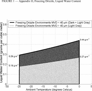
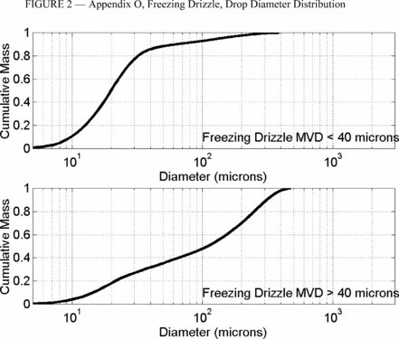
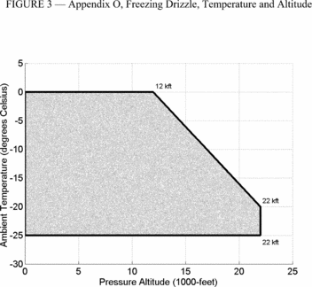
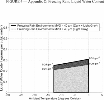
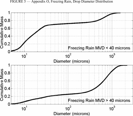
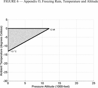
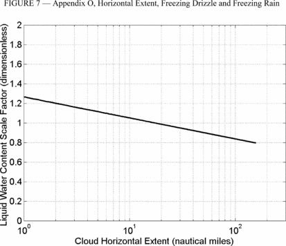 PART II - AIRFRAME
ICE ACCRETIONS FOR SHOWING COMPLIANCE WITH SUBPART B OF THIS PART
(a) General. The most critical ice accretion in terms of airplane performance and handling qualities for each flight phase must be used to show compliance with the applicable airplane performance and handling qualities requirements for icing conditions contained in subpart B of this part. Applicants must demonstrate that the full range of atmospheric icing conditions specified in part I of this Appendix have been considered, including drop diameter distributions, liquid water content, and temperature appropriate to the flight conditions (for example, configuration, speed, angle of attack, and altitude).
(1) For an airplane certified in accordance with § 25.1420(a)(1), the ice accretions for each flight phase are defined in part II, paragraph (b) of this Appendix.
(2) For an airplane certified in accordance with § 25.1420(a)(2), the most critical ice accretion for each flight phase defined in part II, paragraphs (b) and (c) of this Appendix, must be used. For the ice accretions defined in part II, paragraph (c) of this Appendix, only the portion of part I of this Appendix in which the airplane is capable of operating safely must be considered.
(3) For an airplane certified in accordance with § 25.1420(a)(3), the ice accretions for each flight phase are defined in part II, paragraph (c) of this Appendix.
(b) Ice accretions for airplanes certified in accordance with § 25.1420(a)(1) or (2).
(1) En route ice is the en route ice as defined by part II, paragraph (c)(3), of this Appendix, for an airplane certified in accordance with § 25.1420(a)(2), or defined by part II, paragraph (a)(3), of Appendix C of this part, for an airplane certified in accordance with § 25.1420(a)(1), plus:
(i) Pre-detection ice as defined by part II, paragraph (b)(5), of this Appendix; and
(ii) The ice accumulated during the transit of one cloud with a horizontal extent of 17.4 nautical miles in the most critical of the icing conditions defined in part I of this Appendix and one cloud with a horizontal extent of 17.4 nautical miles in the continuous maximum icing conditions defined in Appendix C of this part.
(2) Holding ice is the holding ice defined by part II, paragraph (c)(4), of this Appendix, for an airplane certified in accordance with § 25.1420(a)(2), or defined by part II, paragraph (a)(4), of Appendix C of this part, for an airplane certified in accordance with § 25.1420(a)(1), plus:
(i) Pre-detection ice as defined by part II, paragraph (b)(5), of this Appendix; and
(ii) The ice accumulated during the transit of one cloud with a 17.4 nautical miles horizontal extent in the most critical of the icing conditions defined in part I of this Appendix and one cloud with a horizontal extent of 17.4 nautical miles in the continuous maximum icing conditions defined in Appendix C of this part.
(iii) Except the total exposure to holding ice conditions does not need to exceed 45 minutes.
(3) Approach ice is the more critical of the holding ice defined by part II, paragraph (b)(2), of this Appendix, or the ice calculated in the applicable paragraphs (b)(3)(i) or (ii) of part II, of this Appendix:
(i) For an airplane certified in accordance with § 25.1420(a)(2), the ice accumulated during descent from the maximum vertical extent of the icing conditions defined in part I of this Appendix to 2,000 feet above the landing surface in the cruise configuration, plus transition to the approach configuration, plus:
(A) Pre-detection ice, as defined by part II, paragraph (b)(5), of this Appendix; and
(B) The ice accumulated during the transit at 2,000 feet above the landing surface of one cloud with a horizontal extent of 17.4 nautical miles in the most critical of the icing conditions defined in part I of this Appendix and one cloud with a horizontal extent of 17.4 nautical miles in the continuous maximum icing conditions defined in Appendix C of this part.
(ii) For an airplane certified in accordance with § 25.1420(a)(1), the ice accumulated during descent from the maximum vertical extent of the maximum continuous icing conditions defined in part I of Appendix C to 2,000 feet above the landing surface in the cruise configuration, plus transition to the approach configuration, plus:
(A) Pre-detection ice, as defined by part II, paragraph (b)(5), of this Appendix; and
(B) The ice accumulated during the transit at 2,000 feet above the landing surface of one cloud with a horizontal extent of 17.4 nautical miles in the most critical of the icing conditions defined in part I of this Appendix and one cloud with a horizontal extent of 17.4 nautical miles in the continuous maximum icing conditions defined in Appendix C of this part.
(4) Landing ice is the more critical of the holding ice as defined by part II, paragraph (b)(2), of this Appendix, or the ice calculated in the applicable paragraphs (b)(4)(i) or (ii) of part II of this Appendix:
(i) For an airplane certified in accordance with § 25.1420(a)(2), the ice accretion defined by part II, paragraph (c)(5)(i), of this Appendix, plus a descent from 2,000 feet above the landing surface to a height of 200 feet above the landing surface with a transition to the landing configuration in the icing conditions defined in part I of this Appendix, plus:
(A) Pre-detection ice, as defined in part II, paragraph (b)(5), of this Appendix; and
(B) The ice accumulated during an exit maneuver, beginning with the minimum climb gradient required by § 25.119, from a height of 200 feet above the landing surface through one cloud with a horizontal extent of 17.4 nautical miles in the most critical of the icing conditions defined in part I of this Appendix and one cloud with a horizontal extent of 17.4 nautical miles in the continuous maximum icing conditions defined in Appendix C of this part.
(ii) For an airplane certified in accordance with § 25.1420(a)(1), the ice accumulated in the maximum continuous icing conditions defined in Appendix C of this part, during a descent from the maximum vertical extent of the icing conditions defined in Appendix C of this part, to 2,000 feet above the landing surface in the cruise configuration, plus transition to the approach configuration and flying for 15 minutes at 2,000 feet above the landing surface, plus a descent from 2,000 feet above the landing surface to a height of 200 feet above the landing surface with a transition to the landing configuration, plus:
(A) Pre-detection ice, as described by part II, paragraph (b)(5), of this Appendix; and
(B) The ice accumulated during an exit maneuver, beginning with the minimum climb gradient required by § 25.119, from a height of 200 feet above the landing surface through one cloud with a horizontal extent of 17.4 nautical miles in the most critical of the icing conditions defined in part I of this Appendix and one cloud with a horizontal extent of 17.4 nautical miles in the continuous maximum icing conditions defined in Appendix C of this part.
(5) Pre-detection ice is the ice accretion before detection of flight conditions in this Appendix that require exiting per § 25.1420(a)(1) and (2). It is the pre-existing ice accretion that may exist from operating in icing conditions in which the airplane is approved to operate prior to encountering the icing conditions requiring an exit, plus the ice accumulated during the time needed to detect the icing conditions, followed by two minutes of further ice accumulation to take into account the time for the flightcrew to take action to exit the icing conditions, including coordination with air traffic control.
(i) For an airplane certified in accordance with § 25.1420(a)(1), the pre-existing ice accretion must be based on the icing conditions defined in Appendix C of this part.
(ii) For an airplane certified in accordance with § 25.1420(a)(2), the pre-existing ice accretion must be based on the more critical of the icing conditions defined in Appendix C of this part, or the icing conditions defined in part I of this Appendix in which the airplane is capable of safely operating.
(c) Ice accretions for airplanes certified in accordance with §§ 25.1420(a)(2) or (3). For an airplane certified in accordance with § 25.1420(a)(2), only the portion of the icing conditions of part I of this Appendix in which the airplane is capable of operating safely must be considered.
(1) Takeoff ice is the most critical ice accretion on unprotected surfaces, and any ice accretion on the protected surfaces, occurring between the end of the takeoff distance and 400 feet above the takeoff surface, assuming accretion starts at the end of the takeoff distance in the icing conditions defined in part I of this Appendix.
(2) Final takeoff ice is the most critical ice accretion on unprotected surfaces, and any ice accretion on the protected surfaces appropriate to normal ice protection system operation, between 400 feet and either 1,500 feet above the takeoff surface, or the height at which the transition from the takeoff to the en route configuration is completed and VFTO is reached, whichever is higher. Ice accretion is assumed to start at the end of the takeoff distance in the icing conditions defined in part I of this Appendix.
(3) En route ice is the most critical ice accretion on the unprotected surfaces, and any ice accretion on the protected surfaces appropriate to normal ice protection system operation, during the en route flight phase in the icing conditions defined in part I of this Appendix.
(4) Holding ice is the most critical ice accretion on the unprotected surfaces, and any ice accretion on the protected surfaces appropriate to normal ice protection system operation, resulting from 45 minutes of flight within a cloud with a 17.4 nautical miles horizontal extent in the icing conditions defined in part I of this Appendix, during the holding phase of flight.
(5) Approach ice is the ice accretion on the unprotected surfaces, and any ice accretion on the protected surfaces appropriate to normal ice protection system operation, resulting from the more critical of the:
(i) Ice accumulated in the icing conditions defined in part I of this Appendix during a descent from the maximum vertical extent of the icing conditions defined in part I of this Appendix, to 2,000 feet above the landing surface in the cruise configuration, plus transition to the approach configuration and flying for 15 minutes at 2,000 feet above the landing surface; or
(ii) Holding ice as defined by part II, paragraph (c)(4), of this Appendix.
(6) Landing ice is the ice accretion on the unprotected surfaces, and any ice accretion on the protected surfaces appropriate to normal ice protection system operation, resulting from the more critical of the:
(i) Ice accretion defined by part II, paragraph (c)(5)(i), of this Appendix, plus ice accumulated in the icing conditions defined in part I of this Appendix during a descent from 2,000 feet above the landing surface to a height of 200 feet above the landing surface with a transition to the landing configuration, followed by a go-around at the minimum climb gradient required by § 25.119, from a height of 200 feet above the landing surface to 2,000 feet above the landing surface, flying for 15 minutes at 2,000 feet above the landing surface in the approach configuration, and a descent to the landing surface (touchdown) in the landing configuration; or
(ii) Holding ice as defined by part II, paragraph (c)(4), of this Appendix.
(7) For both unprotected and protected parts, the ice accretion for the takeoff phase must be determined for the icing conditions defined in part I of this Appendix, using the following assumptions:
(i) The airfoils, control surfaces, and, if applicable, propellers are free from frost, snow, or ice at the start of takeoff;
(ii) The ice accretion starts at the end of the takeoff distance;
(iii) The critical ratio of thrust/power-to-weight;
(iv) Failure of the critical engine occurs at VEF; and
(v) Crew activation of the ice protection system is in accordance with a normal operating procedure provided in the airplane flight manual, except that after beginning the takeoff roll, it must be assumed that the crew takes no action to activate the ice protection system until the airplane is at least 400 feet above the takeoff surface.
(d) The ice accretion before the ice protection system has been activated and is performing its intended function is the critical ice accretion formed on the unprotected and normally protected surfaces before activation and effective operation of the ice protection system in the icing conditions defined in part I of this Appendix. This ice accretion only applies in showing compliance to §§ 25.143(j) and 25.207(h).
(e) In order to reduce the number of ice accretions to be considered when demonstrating compliance with the requirements of § 25.21(g), any of the ice accretions defined in this Appendix may be used for any other flight phase if it is shown to be at least as critical as the specific ice accretion defined for that flight phase. Configuration differences and their effects on ice accretions must be taken into account.
(f) The ice accretion that has the most adverse effect on handling qualities may be used for airplane performance tests provided any difference in performance is conservatively taken into account.
[Amdt. 25-140, 79 FR 65528, Nov. 4, 2014]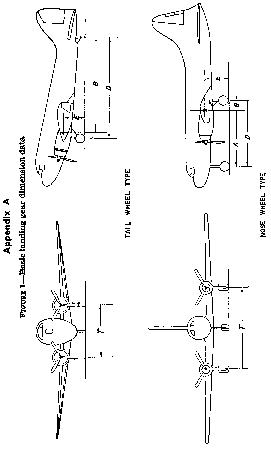
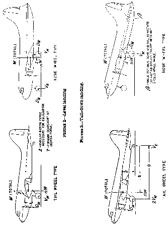
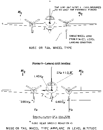
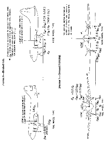
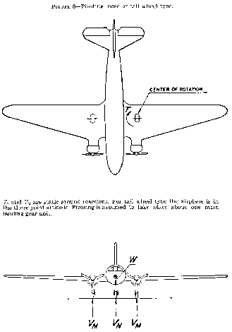

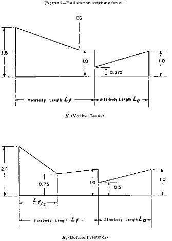
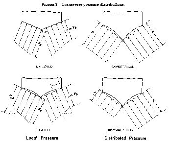
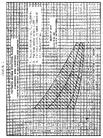
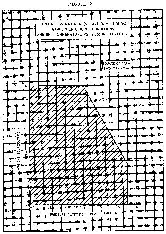
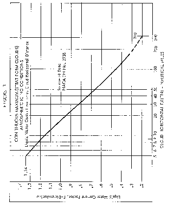
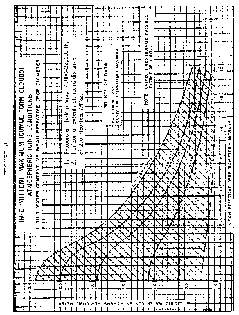
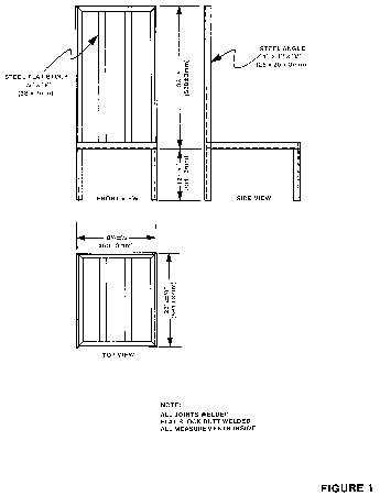
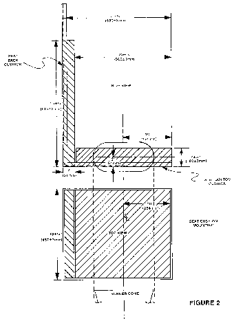
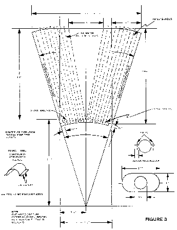
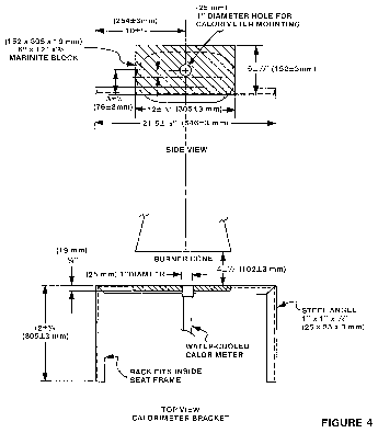
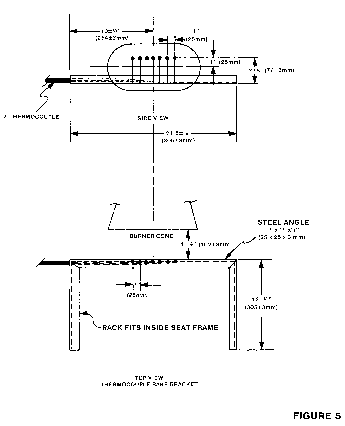 Part III - Test
Method To Determine Flame Penetration Resistance of Cargo
Compartment Liners.
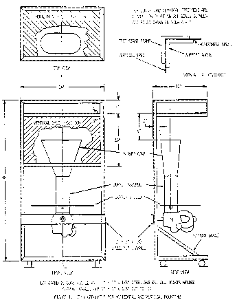
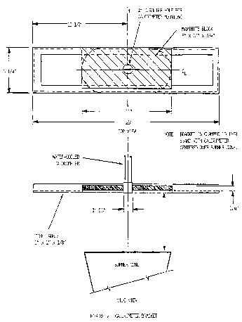
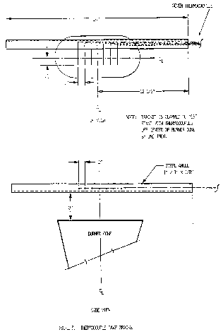 Part IV - Test
Method To Determine the Heat Release Rate From Cabin Materials
Exposed to Radiant Heat.
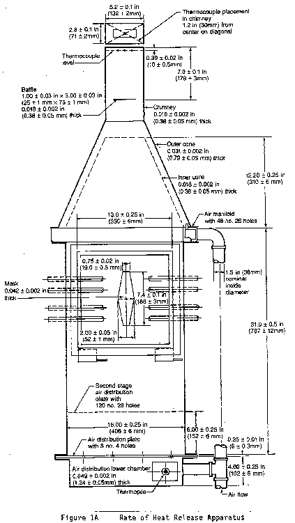
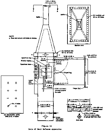
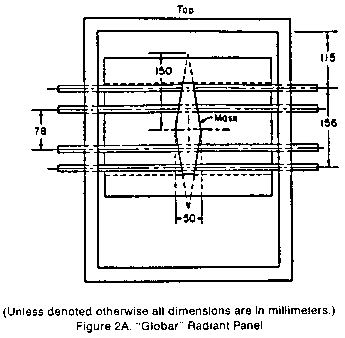
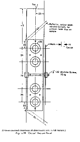
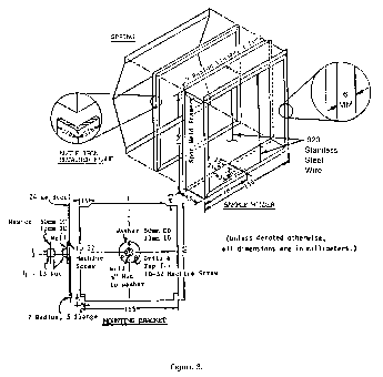
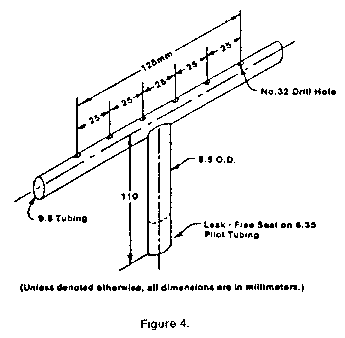
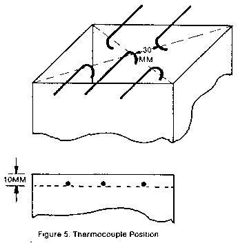 Part V. Test
Method To Determine the Smoke Emission Characteristics of Cabin
Materials
