Title 10
PART 431 APPENDIX B


| Operating temperature class | EER Btu/W |
|---|---|
| Medium | 11 |
| Low | 7 |
| Ice Cream | 5 |
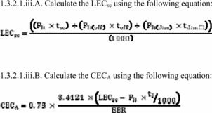
1.3.2.1.iii.C. For remote condensing units, calculate the revised compressor energy consumption (CECR) by adding the CECA to the compressor energy consumption (CEC) measured in AHRI Standard 1200 (I-P)-2010 (incorporated by reference, see § 431.63). The CDEC for the entire case is the sum of the CECR and LECsc (as calculated above) and the fan energy consumption (FEC), anti-condensate energy consumption (AEC), defrost energy consumption (DEC), and condensate evaporator pan energy consumption (PEC) (as measured in AHRI Standard 1200 (I-P)-2010).
1.3.2.1.iii.D. For self-contained units, the TDEC for the entire case is the sum of total daily energy consumption as measured by the AHRI Standard 1200 (I-P)-2010 (incorporated by reference, see § 431.63) test with the lights fully on (TDECo) and CECA, less the decrease in lighting energy use due to lighting occupancy sensors and scheduled lighting controls, as shown in following equation.

1.3.3. Customer display signs/lights. Do not energize supplemental lighting that exists solely for the purposes of advertising or drawing attention to the case and is not integral to the operation of the case.
1.3.4. Condensate pan heaters and pumps. For self-contained equipment only, all electric resistance condensate heaters and condensate pumps must be installed and in operation during the test. This includes the stabilization period (including pull-down), steady-state, and performance testing periods. Prior to the start of the stabilization period as defined by ASHRAE 72-2005 (incorporated by reference, see § 431.63), the condensate pan must be dry. Following the start of the stabilization period, allow any condensate moisture generated to accumulate in the pan. Do not manually add or remove water to or from the condensate pan at any time during the test.
1.3.5. Anti-sweat door heaters. Anti-sweat door heaters must be operational during the entirety of the test procedure. Models with a user-selectable setting must have the heaters energized and set to the maximum usage position. Models featuring an automatic, non-user-adjustable controller that turns on or off based on environmental conditions must be operating in the automatic state. If a unit is not shipped with a controller from the point of manufacture and is intended to be used with an automatic, non-user-adjustable controller, test the unit with a manufacturer-recommended controller that turns on or off based on environmental conditions.
1.3.6. Ultraviolet lights. Do not energize ultraviolet lights during the test.
1.3.7. Illuminated temperature displays and alarms. All illuminated temperature displays and alarms shall be energized and operated during the test as they would be during normal field operation.
1.3.8. Condenser filters. Remove any nonpermanent filters that are provided to prevent particulates from blocking a model's condenser coil.
1.3.9. Refrigeration system security covers. Remove any devices used to secure the condensing unit against unwanted removal.
1.3.10. Night curtains and covers. For display cases sold with night curtains installed, the night curtain shall be employed for 6 hours; beginning 3 hours after the start of the first defrost period. Upon the completion of the 6-hour period, the night curtain shall be raised until the completion of the 24-hour test period.
1.3.11. Grill options. Remove any optional non-standard grills used to direct airflow.
1.3.12. Misting or humidification systems. Misting or humidification systems must be inactive during the test.
1.3.13. Air purifiers. Air purifiers must be inactive during the test.
1.3.14. General purpose outlets. During the test, do not connect any external load to any general purpose outlets contained within a unit.
1.3.15. Crankcase heaters. Crankcase heaters must be operational during the test. If a control system, such as a thermostat or electronic controller, is used to modulate the operation of the crankcase heater, it must be utilized during the test.
1.3.16. Drawers. Drawers are to be treated as identical to doors when conducting the DOE test procedure. Commercial refrigeration equipment with drawers should be configured with the drawer pans that allow for the maximum packing of test simulators and filler packages without the filler packages and test simulators exceeding 90 percent of the refrigerated volume. Packing of test simulators and filler packages shall be in accordance with the requirements for commercial refrigerators without shelves, as specified in section 6.2.3 of ASHRAE 72-2005 (incorporated by reference, see § 431.63).
2. Test Conditions2.1. Integrated Average Temperatures. Conduct the testing required in section 1 of this appendix B, and determine the daily energy consumption at the applicable integrated average temperature in the following table.
| Category | Test procedure | Integrated average temperature |
|---|---|---|
| (i) Refrigerator with Solid Door(s) | AHRI Standard 1200 (I-P)-2010 1 | 38 °F (±2 °F). |
| (ii) Refrigerator with Transparent Door(s) | AHRI Standard 1200 (I-P)-2010 1 | 38 °F (±2 °F). |
| (iii) Freezer with Solid Door(s) | AHRI Standard 1200 (I-P)-2010 1 | 0 °F (±2 °F). |
| (iv) Freezer with Transparent Door(s) | AHRI Standard 1200 (I-P)-2010 1 | 0 °F (±2 °F). |
| (v) Refrigerator-Freezer with Solid Door(s) | AHRI Standard 1200 (I-P)-2010 1 | 38 °F (±2 °F) for refrigerator
compartment. 0 °F (±2 °F) for freezer compartment. |
| (vi) Commercial Refrigerator with a Self-Contained Condensing Unit Designed for Pull-Down Temperature Applications and Transparent Doors | AHRI Standard 1200 (I-P)-2010 1 | 38 °F (±2 °F). |
| (vii) Ice-Cream Freezer | AHRI Standard 1200 (I-P)-2010 1 | −15.0 °F (±2 °F). |
| (viii) Commercial Refrigerator, Freezer, and Refrigerator-Freezer with a Self-Contained Condensing Unit and without Doors | AHRI Standard 1200 (I-P)-2010 1 | (A) 0 °F (±2 °F) for low
temperature applications. (B) 38.0 °F (±2 °F) for medium temperature applications. |
| (ix) Commercial Refrigerator, Freezer, and Refrigerator-Freezer with a Remote Condensing Unit | AHRI Standard 1200 (I-P)-2010 1 | (A) 0 °F (±2 °F) for low
temperature applications. (B) 38.0 °F (±2 °F) for medium temperature applications. |
1 Incorporated by reference, see § 431.63.
2.2. Lowest Application Product Temperature. If a unit of commercial refrigeration equipment is not able to be operated at the integrated average temperature specified in the table in paragraph 2.1 of this appendix, test the unit at the lowest application product temperature (LAPT), as defined in § 431.62. For units equipped with a thermostat, LAPT is the lowest thermostat setting. For remote condensing equipment without a thermostat or other means of controlling temperature at the case, the lowest application product temperature is the temperature achieved with the dew point temperature (as defined in AHRI Standard 1200 (I-P)-2010 (incorporated by reference, see § 431.63)) set to 5 degrees colder than that required to maintain the manufacturer's lowest specified application temperature.
2.3. Testing at NSF Test Conditions. For commercial refrigeration equipment that is also tested in accordance with NSF test procedures (Type I and Type II), integrated average temperatures and ambient conditions used for NSF testing may be used in place of the DOE-prescribed integrated average temperatures and ambient conditions provided they result in a more stringent test. That is, the measured daily energy consumption of the same unit, when tested at the rating temperatures and/or ambient conditions specified in the DOE test procedure, must be lower than or equal to the measured daily energy consumption of the unit when tested with the rating temperatures or ambient conditions used for NSF testing. The integrated average temperature measured during the test may be lower than the range specified by the DOE applicable temperature specification provided in paragraph 2.1 of this appendix, but may not exceed the upper value of the specified range. Ambient temperatures and/or humidity values may be higher than those specified in the DOE test procedure.
3. Volume and Total Display Area3.1. Determination of Volume. Determine the volume of a commercial refrigerator, freezer, refrigerator-freezer, or ice-cream freezer using the method set forth in the HRF-1-2008 (incorporated by reference, see § 431.63), section 3.30, “Volume,” and sections 4.1 through 4.3, “Method for Computing Refrigerated Volume of Refrigerators, Refrigerator-Freezers, Wine Chillers and Freezers.”
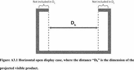
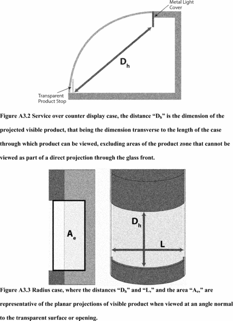
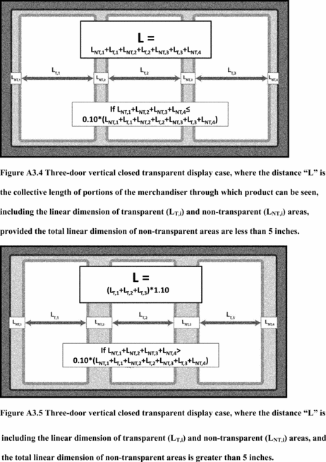
3.2. Determination of Total Display Area. Determine the total display area of a commercial refrigerator, freezer, refrigerator-freezer, or ice-cream freezer using the method set forth in ARI Standard 1200-2006 (incorporated by reference, see § 431.63), but disregarding the specification that “transparent material (≥65% light transmittance) in Appendix D. Specifically, total display area shall be the sum of the projected area(s) of visible product, expressed in ft 2 (i.e., portions through which product can be viewed from an angle normal, or perpendicular, to the transparent area). Determine L as the interior length of the CRE model, provided no more than 5 inches of that length consists of non-transparent material. For those cases with greater than 5 inches of non-transparent area, L shall be determined as the projected linear dimension(s) of visible product plus 5 inches of non-transparent area.
See Figures A3.1, A3.2, and A3.3 as examples of how to calculate the dimensions associated with calculation of total display area. In the diagrams, Dh and L represent the dimensions of the projected visible product.
 [79 FR 22308, Apr.
21, 2014]
[79 FR 22308, Apr.
21, 2014]Appendix B to Subpart G of Part 431 - Uniform Test Method for the Measurement of Standby Loss of Electric Storage Water Heaters and Storage-Type Instantaneous Water Heaters
10:3.0.1.4.19.7.64.6.52 : Appendix B
Appendix B to Subpart G of Part 431 - Uniform Test Method for the Measurement of Standby Loss of Electric Storage Water Heaters and Storage-Type Instantaneous Water HeatersNote: Prior to November 6, 2017, manufacturers must make any representations with respect to the energy use or efficiency of the subject commercial water heating equipment in accordance with the results of testing pursuant to this appendix or the procedures in 10 CFR 431.106 that were in place on January 1, 2016. On and after November 6, 2017, manufacturers must make any representations with respect to energy use or efficiency of electric storage water heaters and storage-type instantaneous water heaters in accordance with the results of testing pursuant to this appendix to demonstrate compliance with the energy conservation standards at 10 CFR 431.110.
1. GeneralDetermine the standby loss in accordance with the following sections of this appendix. Certain sections reference sections of Annex E.1 of ANSI Z21.10.3-2015 (incorporated by reference; see § 431.105). Where the instructions contained in the sections below conflict with instructions in Annex E.1 of ANSI Z21.10.3-2015, the instructions contained in this appendix control.
2. Test Set-Up2.1. Placement of Water Heater. A water heater for installation on combustible floors must be placed on a 3/4-inch plywood platform supported by three 2 × 4-inch runners. If the water heater is for installation on noncombustible floors, suitable noncombustible material must be placed on the platform. When the use of the platform for a large water heater is not practical, the water heater may be placed on any suitable flooring. A wall-mounted water heater must be mounted on a simulated wall section.
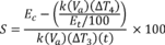
2.2. Installation of Temperature Sensors. Inlet and outlet piping must be turned vertically downward from the connections on a tank-type water heater so as to form heat traps. Temperature sensors for measuring supply water temperature must be installed upstream of the inlet heat trap piping, in accordance with Figure 2.1, 2.2, or 2.3 (as applicable) of this appendix.
The water heater must meet the requirements shown in either Figure 2.1, 2.2, or 2.3 (as applicable) at all times during the conduct of the standby loss test. Any factory-supplied heat traps must be installed per the installation instructions while ensuring the requirements in Figure 2.1, 2.2, or 2.3 are met. All dimensions specified in Figure 2.1, 2.2, and 2.3 are measured from the outer surface of the pipes and water heater outer casing (as applicable).
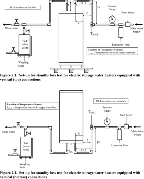
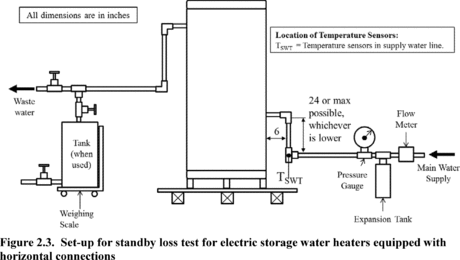
2.3. Installation of Temperature Sensors for Measurement of Mean Tank Temperature. Install temperature sensors inside the tank for measurement of mean tank temperature according to the instructions in paragraph f of Annex E.1 of ANSI Z21.10.3-2015 (incorporated by reference; see § 431.105 rt). Calculate the mean tank temperature as the average of the six installed temperature sensors.
2.4. Piping Insulation. Insulate all water piping external to the water heater jacket, including heat traps and piping that is installed by the manufacturer or shipped with the unit, for at least 4 ft of piping length from the connection at the appliance, with material having an R-value not less than 4 °F·ft 2·h/Btu. Ensure that the insulation does not contact any appliance surface except at the location where the pipe connections penetrate the appliance jacket or enclosure.
2.5. Temperature and Pressure Relief Valve Insulation. If the manufacturer or has not provided a temperature and pressure relief valve, one shall be installed and insulated as specified in section 2.4 of this appendix.
2.6. Energy Consumption. Install equipment that determines, within ± 1 percent, the quantity of electricity consumed by factory-supplied water heater components.
3. Test Conditions 3.1. Water Supply3.1.1. Water Supply Pressure. The pressure of the water supply must be maintained between 40 psi and the maximum pressure specified by the manufacturer of the unit being tested. The accuracy of the pressure-measuring devices must be within ± 1.0 pounds per square inch (psi).
3.1.2. Water Supply Temperature. When filling the tank with water prior to the soak-in period, maintain the supply water temperature at 70 °F ± 2 °F.
3.1.3. Isolate the water heater using a shutoff valve in the supply line with an expansion tank installed in the supply line downstream of the shutoff valve. There must be no shutoff means between the expansion tank and the appliance inlet.
3.2. Electrical Supply. Maintain the electrical supply voltage to within ± 5 percent of the voltage specified on the water heater nameplate. If a voltage range is specified on the nameplate, maintain the voltage to within ± 5 percent of the center of the voltage range specified on the nameplate.
3.3. Ambient Room Temperature. During the soak-in period and the standby loss test, maintain the ambient room temperature at 75 °F ± 10 °F at all times. Measure the ambient room temperature at 1-minute intervals during these periods, except for the soak-in period. Measure the ambient room temperature once before beginning the soak-in period, and ensure no actions are taken during the soak-in period that would cause the ambient room temperature to deviate from the allowable range. Measure the ambient room temperature at the vertical mid-point of the water heater and approximately 2 feet from the water heater jacket. Shield the sensor against radiation. Calculate the average ambient room temperature for the standby loss test. During the standby loss test, the ambient room temperature must not vary by more than ± 5.0 °F at any reading from the average ambient room temperature.
3.4. Maximum Air Draft. During the standby loss test, the water heater must be located in an area protected from drafts of more than 50 ft/min. Prior to beginning the standby loss test, measure the air draft within three feet of the jacket of the water heater to ensure this condition is met. Ensure that no other changes that would increase the air draft are made to the test set-up or conditions during the conduct of the test.
3.5. Setting the Tank Thermostat(s). Before starting the required soak-in period, the thermostat setting(s) must first be obtained as explained in the following sections. The thermostat setting(s) must be obtained by starting with the tank full of water at 70 °F ± 2 °F. After the tank is completely filled with water at 70 °F ± 2 °F, turn off the water flow, and set the thermostat(s) as follows.
3.5.1. For water heaters with a single thermostat, the thermostat setting must be set so that the maximum mean tank temperature after cut-out is 140 °F ± 5 °F.
3.5.2. For water heaters with multiple adjustable thermostats, set only the topmost and bottommost thermostats, and turn off any other thermostats for the duration of the standby loss test. Set the topmost thermostat first to yield a maximum mean water temperature after cut-out of 140 °F ± 5 °F, as calculated using only the temperature readings measured at locations in the tank higher than the heating element corresponding to the topmost thermostat (the lowermost heating element corresponding to the topmost thermostat if the thermostat controls more than one element). While setting the topmost thermostat, all lower thermostats must be turned off so that no elements below that (those) corresponding to the topmost thermostat are in operation. After setting the topmost thermostat, set the bottommost thermostat to yield a maximum mean water temperature after cut-out of 140 °F ± 5 °F. When setting the bottommost thermostat, calculate the mean tank temperature using all the temperature sensors installed in the tank as per section 2.3 of this appendix.
3.6. Data Collection Intervals. Follow the data recording intervals specified in the following sections.
3.6.1. Soak-In Period. Measure the ambient room temperature, in °F, every minute during the soak-in period.
3.6.2. Standby Loss Test. Follow the data recording intervals specified in Table 3.1 of this appendix. Additionally, the electricity consumption over the course of the entire test must be measured and used in calculation of standby loss.
Table 3.1 - Data To Be Recorded Before and During the Standby Loss Test
| Item recorded | Before test | Every 1 minute a |
|---|---|---|
| Air draft, ft/min | X | |
| Time, minutes/seconds | X | |
| Mean tank temperature, °F | X b | |
| Ambient room temperature, °F | X |
Notes:
a These measurements are to be recorded at the start and end of the test, as well as every minute during the test.
b Mean tank temperature is calculated as the average of the 6 tank temperature sensors, installed per section 2.3 of this appendix.
4. Determination of Storage Volume. Determine the storage volume by subtracting the tare weight, measured while the system is dry and empty, from the weight of the system when filled with water and dividing the resulting net weight of water by the density of water at the measured water temperature. The volume of water contained in the water heater must be computed in gallons.
5. Standby Loss Test5.1. If no settings on the water heater have changed and the water heater has not been turned off since a previously run standby loss test, skip to section 5.3 of this appendix. Otherwise, conduct the soak-in period according to section 5.2 of this appendix.
5.2. Soak-In Period. Conduct a soak-in period, in which the water heater must sit without any draws taking place for at least 12 hours. Begin the soak-in period after setting the tank thermostat(s) as specified in section 3.5 of this appendix, and maintain these settings throughout the soak-in period.
5.3. Begin the standby loss test at the first cut-out following the end of the soak-in period (if applicable), or at a cut-out following the previous standby loss test (if applicable). Allow the water heater to remain in standby mode. At this point, do not change any settings on the water heater until measurements for the standby loss test are finished. Begin recording applicable parameters as specified in section 3.6.2 of this appendix.
5.4. At the second cut-out, record the time and ambient room temperature, and begin measuring the electric consumption. Record the initial mean tank temperature and initial ambient room temperature. For the remainder of the test, continue recording the applicable parameters specified in section 3.6.2 of this appendix.
5.5. Stop the test after the first cut-out that occurs after 24 hours, or at 48 hours, whichever comes first.
5.6. Immediately after conclusion of the standby loss test, record the total electrical energy consumption, the final ambient room temperature, the duration of the standby loss test, and if the test ends at 48 hours without a cut-out, the final mean tank temperature, or if the test ends after a cut-out, the maximum mean tank temperature that occurs after the cut-out. Calculate the average of the recorded values of the mean tank temperature and of the ambient air temperatures taken at each measurement interval, including the initial and final values.
5.7. Standby Loss Calculation. To calculate the standby loss, follow the steps below:
5.7.1 The standby loss expressed as a percentage (per hour) of the heat content of the stored water above room temperature must be calculated using the following equation:
 Where,
ΔT3 = Average value of the mean tank temperature minus the average
value of the ambient room temperature, expressed in °F ΔT4 = Final
mean tank temperature measured at the end of the test minus the
initial mean tank temperature measured at the start of the test,
expressed in °F k = 8.25 Btu/gallon· °F, the nominal specific heat
of water Va = Volume of water contained in the water heater in
gallons measured in accordance with section 4 of this appendix Et =
Thermal efficiency = 98 percent for electric water heaters with
immersed heating elements Ec = Electrical energy consumed by the
water heater during the duration of the test in Btu t = Total
duration of the test in hours S = Standby loss, the average hourly
energy required to maintain the stored water temperature expressed
as a percentage of the heat content of the stored water above room
temperature [81 FR 79328, Nov. 10, 2016]
Where,
ΔT3 = Average value of the mean tank temperature minus the average
value of the ambient room temperature, expressed in °F ΔT4 = Final
mean tank temperature measured at the end of the test minus the
initial mean tank temperature measured at the start of the test,
expressed in °F k = 8.25 Btu/gallon· °F, the nominal specific heat
of water Va = Volume of water contained in the water heater in
gallons measured in accordance with section 4 of this appendix Et =
Thermal efficiency = 98 percent for electric water heaters with
immersed heating elements Ec = Electrical energy consumed by the
water heater during the duration of the test in Btu t = Total
duration of the test in hours S = Standby loss, the average hourly
energy required to maintain the stored water temperature expressed
as a percentage of the heat content of the stored water above room
temperature [81 FR 79328, Nov. 10, 2016]Appendix B to Subpart Q of Part 431 - Uniform Test Method for the Measurement of Energy Consumption of Refrigerated Bottled or Canned Beverage Vending Machines
10:3.0.1.4.19.17.83.6.58 : Appendix B
Appendix B to Subpart Q of Part 431 - Uniform Test Method for the Measurement of Energy Consumption of Refrigerated Bottled or Canned Beverage Vending Machines Note:After January 27, 2016, manufacturers must make any representations with respect to energy use or efficiency in accordance with the results of testing pursuant to appendix A of this subpart to demonstrate compliance with the energy conservation standards at 10 CFR 431.296, for which compliance was required as of August 31, 2012. Alternatively, manufacturers may make representations based on testing in accordance with this appendix prior to the compliance date of any amended energy conservation standards, provided that such representations demonstrate compliance with such amended energy conservation standards. Any representations made on or after the compliance date of any amended energy conservation standards, must be made in accordance with the results of testing pursuant to this appendix. Any representations made with respect to the energy use or efficiency of such refrigerated beverage vending machines must be in accordance with whichever version is selected.
1. General. Section 3, “Definitions”; section 4, “Instruments”; section 5, “Vendible Capacity”; section 6, “Test Conditions”; section 7.1, “Test Procedures - General Requirements”; and section 7.2, “Energy Consumption Test” of ANSI/ASHRAE 32.1 (incorporated by reference; see § 431.293) apply to this appendix except as noted throughout this appendix. In cases where there is a conflict, the language of the test procedure in this appendix takes precedence over ANSI/ASHRAE 32.1.
1.1. Instruments. In addition to the instrument accuracy requirements in section 3, “Instruments,” of ANSI/ASHRAE 32.1 (incorporated by reference, see § 431.293), humidity shall be measured with a calibrated instrument accurate to ±2 percent RH at the specified ambient relative humidity condition specified in section 2.1.3 of this appendix.
1.2. Definitions. In addition to the definitions specified in section 3, “Definitions,” of ANSI/ASHRAE 32.1 (incorporated by reference, see § 431.293) the following definitions are also applicable to this appendix.
Accessory low power mode means a state in which a beverage vending machine's lighting and/or other energy-using systems are in low power mode, but that is not a refrigeration low power mode. Functions that may constitute an accessory low power mode may include, for example, dimming or turning off lights, but does not include adjustment of the refrigeration system to elevate the temperature of the refrigerated compartment(s).
External accessory standby mode means the mode of operation in which any external, integral customer display signs, lighting, or digital screens are connected to mains power; do not produce the intended illumination, display, or interaction functionality; and can be switched into another mode automatically with only a remote user-generated or an internal signal.
Instantaneous average next-to-vend beverage temperature means the spatial average of all standard test packages in the next-to-vend beverages positions at a given time.
Integrated average temperature means the average temperature of all standard test package measurements in the next-to-vend beverage positions taken over the duration of the test, expressed in degrees Fahrenheit ( °F).
Low power mode means a state in which a beverage vending machine's lighting, refrigeration, and/or other energy-using systems are automatically adjusted (without user intervention) such that they consume less energy than they consume in an active vending environment.
Lowest application product temperature means the lowest integrated average temperature a given basic model is capable of maintaining so as to comply with the temperature stabilization requirements specified in section 7.2.2.2 of ANSI/ASHRAE 32.1 (incorporated by reference, see § 431.293).
Refrigeration low power mode means a state in which a beverage vending machine's refrigeration system is in low power mode because of elevation of the temperature of the refrigerated compartment(s). To qualify as low power mode, the unit must satisfy the requirements described in section 2.3.2.1 of this appendix.
2. Test Procedure.
2.1. Test Conditions. The test conditions specified in section 6, “Test Conditions” of ANSI/ASHRAE 32.1 (incorporated by reference, see § 431.293) apply to this appendix except that in section 6.1, “Voltage and Frequency,” of ANSI/ASHRAE 32.1, the voltage and frequency tolerances specified in section 6.1.a of ANSI/ASHRAE 32.1 also apply equivalently to section 6.1.b of ANSI/ASHRAE 32.1 for equipment with dual nameplate voltages.
2.1.1. Average Beverage Temperature. The integrated average temperature measured during the test must be within ±1 °F of the value specified in Table B.1 of this appendix or the lowest application product temperature for models tested in accordance with paragraph 2.1.3 of this appendix. The measurement of integrated average temperature must begin after temperature stabilization has been achieve and continue for the following 24 consecutive hours. All references to “Table 1” in ANSI/ASHRAE 32.1 (incorporated by reference, see § 431.293) shall instead be interpreted as references to Table B.1 of this appendix and all references to “average beverage temperature” in ANSI/ASHRAE 32.1 shall instead be interpreted as references to the integrated average temperature as defined in section 1.2 of this appendix, except as noted in section 2.1.1.1 of this appendix.
2.1.1.1. Temperature Stabilization. Temperature stabilization shall be determined in accordance with section 7.2.2.2 of ANSI/ASHRAE 32.1 (incorporated by reference § 431.293), except that the reference to “average beverage temperature” shall instead refer to the “instantaneous average next-to-vend beverage temperature,” as defined in section 1.2 of this appendix, and the reference to “Table 1” shall instead refer to Table A.1 of this appendix. That is, temperature stabilization is considered to be achieved 24 hours after the instantaneous average next-to-vend beverage temperature reaches the specified value (see Table A.1) and energy consumption for two successive 6 hour periods are within 2 percent of each other.
2.1.2. Ambient Test Conditions. The refrigerated bottled or canned beverage vending machine must be tested at the test conditions and tolerances specified in the following Table B.1 of this appendix. The specified ambient temperature and humidity conditions shall be maintained within the ranges specified for each recorded measurement. All references to “Table 1” in ANSI/ASHRAE 32.1 (incorporated by reference, see § 431.293) shall instead be interpreted as references to Table B.1 of this appendix. In contrast to the requirements of section 6.1 and Table 1 of ANSI/ASHRAE 32.1, conduct testing only one time at the conditions referenced in Table B.1 of this appendix. Testing at alternate ambient conditions is not required or permitted.
Table B.1 - Ambient Temperature and Relative Humidity Specified Value and Tolerance
| Test and pretest condition | Value | Tolerance | Acceptable range (based on value and tolerance) |
|---|---|---|---|
| Instantaneous Average Next-to-Vend Temperature | 36 °F | ±1 °F | 35-37 °F. |
| Integrated Average Temperature | 36 °F | ±1 °F | N/A (value is averaged throughout test). |
| Ambient Temperature | 75 °F | ±2 °F | 73-77 °F. |
| Relative Humidity | 45 percent RH | ±5 percent RH | 40-50 percent RH. |
2.1.3. Lowest Application Product Temperature. If a refrigerated bottled or canned beverage vending machine is not capable of maintaining an integrated average temperature of 36 °F (±1 °F) during the 24 hour test period, the unit must be tested at the lowest application product temperature, as defined in section 1.2 of this appendix. For refrigerated bottled or canned beverage vending machines equipped with a thermostat, the lowest application product temperature is the integrated average temperature achieved at the lowest thermostat setting.
2.2. Equipment Installation and Test Set Up. Except as provided in this section 2.2 of appendix, the test procedure for energy consumption of refrigerated bottled or canned beverage vending machines shall be conducted in accordance with the methods specified in sections 7.1 through 7.2.2.3 under “Test Procedures” of ANSI/ASHRAE 32.1 (incorporated by reference, see § 431.293).
2.2.1. Equipment Loading. Configure refrigerated bottled or canned beverage vending machines to hold the maximum number of standard products, and place standard test packages in the refrigerated compartment(s) as specified in section 2.2.1.1 or 2.2.1.2 of this appendix.
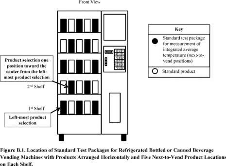
2.2.1.1. Placement of Standard Test Packages for Equipment with Products Arranged Horizontally. For refrigerated bottled or canned beverage vending machines with products arranged horizontally (e.g., on shelves or in product spirals), place standard test packages in the refrigerated compartment(s) in the following locations, as shown in Figure B.1:
(a) For odd-number shelves, when counting starting from the bottom shelf, standard test packages shall be placed at:
(1) The left-most next-to-vend product location;
(2) The right-most next-to-vend product location; and
(3) For equipment with greater than or equal to five product locations on each shelf, either:
(i) The next-to-vend product location in the center of the shelf (i.e., equidistant from the left-most and right-most next-to-vend product locations) if there are an odd number of next-to-vend products on the shelf or,
(ii) The next-to-vend product location immediately to the right and the left of the center position if there are an even number of next-to-vend products on the shelf.
(b) For even-numbered shelves, when counting from the bottom shelf, standard test packages shall be places at either:
(1) For equipment with less than or equal to six next-to-vend product locations on each shelf, the next-to-vend product location(s);
(i) One position towards the center from the left-most next-to-vend product location; and
(ii) One location towards to the center from the right-most next-to-vend product location; or
(2) For equipment with greater than six next-to-vend product locations on each shelf, the next-to-vend product locations:
(i) Two selections towards the center from the left-most next-to-vend product location; and
(ii) Two locations towards to the center from the right-most next-to-vend product location.
2.2.1.2. Placement of Standard Test Packages for Equipment with Products Arranged Vertically. For refrigerated bottled or canned beverage vending machines with products arranged vertically (e.g., in stacks), place standard test packages in the refrigerated compartment(s) in each next-to-vend product location.
2.2.1.3. Loading of Combination Vending Machines. For combination vending machines, the non-refrigerated compartment(s) must not be loaded with any standard products, test packages, or other vendible merchandise.
2.2.1.4. Standard Products. The standard product shall be standard 12-ounce aluminum beverage cans filled with a liquid with a density of 1.0 grams per milliliter (g/mL) ±0.1 g/mL at 36 °F. For product storage racks that are not capable of vending 12-ounce cans, but are capable of vending 20-ounce bottles, the standard product shall be 20-ounce plastic bottles filled with a liquid with a density of 1.0 g/mL ±0.1 g/mL at 36 °F. For product storage racks that are not capable of vending 12-ounce cans or 20-ounce bottles, the standard product shall be the packaging and contents specified by the manufacturer in product literature as the standard product (i.e., the specific merchandise the refrigerated bottled or canned beverage vending machine is designed to vend).
2.2.1.5. Standard Test Packages. A standard test package is a standard product, as specified in 2.2.1.4 of this appendix, altered to include a temperature-measuring instrument at its center of mass.
2.2.2. Sensor Placement. The integrated average temperature of next-to-vend beverages shall be measured in standard test packages in the next-to-vend product locations specified in section 2.2.1.1 of this appendix. Do not run the thermocouple wire and other measurement apparatus through the dispensing door; the thermocouple wire and other measurement apparatus must be configured and sealed so as to minimize air flow between the interior refrigerated volume and the ambient room air. If a manufacturer chooses to employ a method other than routing thermocouple and sensor wires through the door gasket and ensuring the gasket is compressed around the wire to ensure a good seal, then it must maintain a record of the method used in the data underlying that basic model's certification pursuant to 10 CFR 429.71.
2.2.3. Vending Mode Test Period. The vending mode test period begins after temperature stabilization has been achieved, as described in ANSI/ASHRAE 32.1 section 7.2.2.2 (incorporated by reference, see § 431.293) and continues for 18 hours for equipment with an accessory low power mode or for 24 hours for equipment without an accessory low power mode. For the vending mode test period, equipment that has energy-saving features that cannot be disabled shall have those features set to the most energy-consuming settings, except for as specified in section 2.2.4 of this appendix. In addition, all energy management systems shall be disabled. Instead of testing pursuant to sections 7.1.1(d) and 7.2.2.4 of ANSI/ASHRAE 32.1, provide, if necessary, any physical stimuli or other input to the machine needed to prevent automatic activation of low power modes during the vending mode test period.
2.2.4. Accessory Low Power Mode Test Period. For equipment with an accessory low power mode, the accessory low power mode may be engaged for 6 hours, beginning 18 hours after the temperature stabilization requirements established in section 7.2.2.2 of ANSI/ASHRAE 32.1 (incorporated by reference, see § 431.293) have been achieved, and continuing until the end of the 24-hour test period. During the accessory low power mode test, operate the refrigerated bottled or canned beverage vending machine with the lowest energy-consuming lighting and control settings that constitute an accessory low power mode. The specification and tolerances for integrated average temperature in Table B.1 of this appendix still apply, and any refrigeration low power mode must not be engaged. Instead of testing pursuant to sections 7.1.1(d) and 7.2.2.4 of ANSI/ASHRAE 32.1, provide, if necessary, any physical stimuli or other input to the machine needed to prevent automatic activation of refrigeration low power modes during the accessory low power mode test period.
2.2.5. Accessories. Unless specified otherwise in this appendix, all standard components that would be used during normal operation of the basic model in the field and are necessary to provide sufficient functionality for cooling and vending products in field installations (i.e., product inventory, temperature management, product merchandising(including, e.g., lighting or signage), product selection, and product transport and delivery) shall be in place during testing and shall be set to the maximum energy-consuming setting if manually adjustable. Components not necessary for the inventory, temperature management, product merchandising (e.g., lighting or signage), product selection, or product transport and delivery shall be de-energized. If systems not required for the primary functionality of the machine as stated in this section cannot be de-energized without preventing the operation of the machine, then they shall be placed in the lowest energy consuming state Components with controls that are permanently operational and cannot be adjusted by the machine operator shall be operated in their normal setting and consistent with the requirements of 2.2.3 and 2.2.4 of this appendix. The specific components and accessories listed in the subsequent sections shall be operated as stated during the test, except when controlled as part of a low power mode during the low power mode test period.
2.2.5.1 Payment Mechanisms. Refrigerated bottled or canned beverage vending machines shall be tested with no payment mechanism in place, the payment mechanism in-place but de-energized, or the payment mechanism in place but set to the lowest energy consuming state, if it cannot be de-energized. A default payment mechanism energy consumption value of 0.20 kWh/day shall be added to the primary rated energy consumption per day, as noted in section 2.3 of this appendix.
2.2.5.2. Internal Lighting. All lighting that is contained within or is part of the internal physical boundary of the refrigerated bottled or canned beverage vending machine, as established by the top, bottom, and side panels of the equipment, shall be placed in its maximum energy consuming state.
2.2.5.3. External Customer Display Signs, Lights, and Digital Screens. All external customer display signs, lights, and digital screens that are independent from the refrigeration or vending performance of the refrigerated bottled or canned beverage vending machine must be disconnected, disabled, or otherwise de-energized for the duration of testing. Customer display signs, lighting, and digital screens that are integrated into the beverage vending machine cabinet or controls such that they cannot be de-energized without disabling the refrigeration or vending functions of the refrigerated bottled or canned beverage vending machine or modifying the circuitry must be placed in external accessory standby mode, if available, or their lowest energy-consuming state. Digital displays that also serve a vending or money processing function must be placed in the lowest energy-consuming state that still allows the money processing feature to function.
2.2.5.4. Anti-sweat or Other Electric Resistance Heaters. Anti-sweat or other electric resistance heaters must be operational during the entirety of the test procedure. Units with a user-selectable setting must have the heaters energized and set to the most energy-consumptive position. Units featuring an automatic, non-user-adjustable controller that turns on or off based on environmental conditions must be operating in the automatic state. Units that are not shipped with a controller from the point of manufacture, but are intended to be used with a controller, must be equipped with an appropriate controller when tested.
2.2.5.5. Condensate Pan Heaters and Pumps. All electric resistance condensate heaters and condensate pumps must be installed and operational during the test. Prior to the start of the test, including the 24 hour period used to determine temperature stabilization prior to the start of the test period, as described in ANSI/ASHRAE 32.1 section 7.2.2.2 (incorporated by reference, see § 431.293), the condensate pan must be dry. For the duration of the test, including the 24 hour time period necessary for temperature stabilization, allow any condensate moisture generated to accumulate in the pan. Do not manually add or remove water from the condensate pan at any time during the test. Any automatic controls that initiate the operation of the condensate pan heater or pump based on water level or ambient conditions must be enabled and operated in the automatic setting.
2.2.5.6. Illuminated Temperature Displays. All illuminated temperature displays must be energized and operated during the test the same way they would be energized and operated during normal field operation, as recommended in manufacturer product literature, including manuals.
2.2.5.7. Condenser Filters. Remove any nonpermanent filters provided to prevent particulates from blocking a model's condenser coil.
2.2.5.8. Security Covers. Remove any devices used to secure the model from theft or tampering.
2.2.5.9. General Purpose Outlets. During the test, do not connect any external load to any general purpose outlets available on a unit.
2.2.5.10. Crankcase Heaters and Other Electric Resistance Heaters for Cold Weather. Crankcase heaters and other electric resistance heaters for cold weather must be operational during the test. If a control system, such as a thermostat or electronic controller, is used to modulate the operation of the heater, it must be activated during the test and operated in accordance with the manufacturer's instructions.
2.2.6. Sampling and Recording of Data. Record the data listed in section 7.2.2.3 of ANSI/ASHRAE 32.1 (incorporated by reference, see § 431.293), at least every 1 minute. For the purpose of this section, “average beverage temperature,” listed in section 7.2.2.3 of ANSI/ASHRAE 32.1, means “instantaneous average next-to-vend beverage temperature.”
2.3. Determination of Daily Energy Consumption. In section 7.2.3.1 of ANSI/ASHRAE 32.1 (incorporated by reference, see § 431.293), the primary rated energy consumption per day (ED) shall be the energy measured during the vending mode test period and accessory low power mode test period, as specified in sections 2.2.3 and 2.2.4 of this appendix, as applicable.
2.3.1. Energy Consumption of Payment Mechanisms. Calculate the sum of:
(a) The default payment mechanism energy consumption value from section 2.2.5.1 and
(b) The primary rated energy consumption per day (ED), in kWh, and determined in accordance with the calculation procedure in section 7.2.3.1, “Calculation of Daily Energy Consumption,” of ANSI/ASHRAE 32.1 (incorporated by reference, see § 431.293).
2.3.2. Refrigeration Low Power Mode. For refrigerated bottled or canned beverage vending machines with a refrigeration low power mode, multiply the value determined in section 2.3.1 of this appendix by 0.97 to determine the daily energy consumption of the unit tested. For refrigerated bottled or canned beverage vending machines without a refrigeration low power mode, the value determined in section 2.3.1 is the daily energy consumption of the unit tested.
2.3.2.1. Refrigeration Low Power Mode Validation Test Method. This test method is not required for the certification of refrigerated bottled or canned beverage vending machines. To verify the existence of a refrigeration low power mode, initiate the refrigeration low power mode in accordance with manufacturer instructions contained in product literature and manuals, after completion of the 6-hour low power mode test period. Continue recording all the data specified in section 2.2.6 of this appendix until existence of a refrigeration low power mode has been confirmed or denied. The refrigerated bottled or canned beverage vending machine shall be deemed to have a refrigeration low power mode if either:
(a) The following three requirements have been satisfied:
(1) The instantaneous average next-to-vend beverage temperature must reach at least 4 °F above the integrated average temperature or lowest application product temperature, as applicable, within 6 hours.
(2) The instantaneous average next-to-vend beverage temperature must be maintained at least 4 °F above the integrated average temperature or lowest application product temperature, as applicable, for at least 1 hour.
(3) After the instantaneous average next-to-vend beverage temperature is maintained at or above 4 °F above the integrated average temperature or lowest application product temperature, as applicable, for at least 1 hour, the refrigerated beverage vending machine must return to the specified integrated average temperature or lowest application product temperature, as applicable, automatically without direct physical intervention.
(b) Or, the compressor does not cycle on for the entire 6 hour period, in which case the instantaneous average beverage temperature does not have to reach 4 °F above the integrated average temperature or lowest application product temperature, as applicable, but, the equipment must still automatically return to the integrated average temperature or lowest application product temperature, as applicable, after the 6 hour period without direct physical intervention.
2.3.3. Calculations and Rounding. In all cases, the primary rated energy consumption per day (ED) must be calculated with raw measured values and the final result rounded to units of 0.01 kWh/day.
3. Determination of Refrigeration Volume, Vendible Capacity, and Surface Area.
3.1. Refrigerated Volume. Determine the “refrigerated volume” of refrigerated bottled or canned beverage vending machines in accordance with Appendix C, “Measurement of Volume,” of ANSI/ASHRAE 32.1 (incorporated by reference, see § 431.293). For combination vending machines, the “refrigerated volume” does not include any non-refrigerated compartment(s).
3.2. Vendible Capacity. Determine the “vendible capacity” of refrigerated bottled or canned beverage vending machines in accordance with the first paragraph of section 5, “Vending Machine Capacity,” of ANSI/ASHRAE 32.1 (incorporated by reference, see § 431.293). For combination vending machines, the “vendible capacity” includes only the capacity of any portion of the refrigerated bottled or canned beverage vending machine that is refrigerated and does not include the capacity of the non-refrigerated compartment(s).
3.3. Determination of Surface Area. Note: This section is not required for the certification of refrigerated bottled or canned beverage vending machines. Determine the surface area of each beverage vending machine as the length multiplied by the height of outermost surface of the beverage vending machine cabinet, measured from edge to edge excluding any legs or other protrusions that extend beyond the dimensions of the primary cabinet. Determine the transparent and non-transparent areas on each side of a beverage vending machine as the total surface area of material that is transparent or is not transparent, respectively.
[80 FR 45793, July 31, 2015]Appendix B to Subpart R of Part 431 - Uniform Test Method for the Measurement of R-Value for Envelope Components of Walk-In Coolers and Walk-In Freezers
10:3.0.1.4.19.18.85.7.60 : Appendix B
Appendix B to Subpart R of Part 431 - Uniform Test Method for the Measurement of R-Value for Envelope Components of Walk-In Coolers and Walk-In Freezers 1.0 ScopeThis appendix covers the test requirements used to measure the R-value of non-display panels and non-display doors of a walk-in cooler or walk-in freezer.
2.0 DefinitionsThe definitions contained in § 431.302 apply to this appendix.
3.0 Additional Definitions3.1 Edge region means a region of the panel that is wide enough to encompass any framing members. If the panel contains framing members (e.g., a wood frame) then the width of the edge region must be as wide as any framing member plus an additional 2 in. ± 0.25 in.
4.0 Test Methods, Measurements, and Calculations4.1 The R value shall be the 1/K factor multiplied by the thickness of the panel.
4.2 The K factor shall be based on ASTM C518 (incorporated by reference; see § 431.303).
4.3 For calculating the R value for freezers, the K factor of the foam at 20 ± 1 degrees Fahrenheit (average foam temperature) shall be used. Test results from a test sample 1 ±0.1-inches in thickness may be used to determine the R value of panels with various foam thickness as long as the foam is of the same final chemical form.
4.4 For calculating the R value for coolers, the K factor of the foam at 55 ± 1 degrees Fahrenheit (average foam temperature) shall be used. Test results from a test sample 1 ± 0.1-inches in thickness may be used to determine the R value of panels with various foam thickness as long as the foam is of the same final chemical form.
4.5 Foam shall be tested after it is produced in its final chemical form. For foam produced inside of a panel (“foam-in-place”), “final chemical form” means the foam is cured as intended and ready for use as a finished panel. For foam produced as board stock (typically polystyrene), “final chemical form” means after extrusion and ready for assembly into a panel or after assembly into a panel. Foam from foam-in-place panels must not include any structural members or non-foam materials. Foam produced as board stock may be tested prior to its incorporation into a final panel. A test sample 1 ± 0.1-inches in thickness must be taken from the center of a panel and any protective skins or facers must be removed. A high-speed band-saw and a meat slicer are two types of recommended cutting tools. Hot wire cutters or other heated tools must not be used for cutting foam test samples. The two surfaces of the test sample that will contact the hot plate assemblies (as defined in ASTM C518 (incorporated by reference, see § 431.303)) must both maintain ±0.03 inches flatness tolerance and also maintain parallelism with respect to one another within ±0.03 inches. Testing must be completed within 24 hours of samples being cut for testing.
4.6 Internal non-foam member and/or edge regions shall not be considered when testing in accordance with ASTM C518 (incorporated by reference, see § 431.303).
4.7 For panels consisting of two or more layers of dissimilar insulating materials (excluding facers or protective skins), test each material as described in sections 4.1 through 4.6 of this appendix. For a panel with N layers of insulating material, the overall R-Value shall be calculated as follows:
 Where: ki
is the k factor of the ith material as measured by ASTM C518,
(incorporated by reference, see § 431.303); ti is the thickness of
the ith material that appears in the panel; and N is the total
number of material layers that appears in the panel. [81 FR 95803,
Dec. 28, 2016]
Where: ki
is the k factor of the ith material as measured by ASTM C518,
(incorporated by reference, see § 431.303); ti is the thickness of
the ith material that appears in the panel; and N is the total
number of material layers that appears in the panel. [81 FR 95803,
Dec. 28, 2016]Appendix B to Subpart Y of Part 431 - Uniform Test Method for the Measurement of Energy Efficiency of Dedicated-Purpose Pool Pumps
10:3.0.1.4.19.25.89.7.65 : Appendix B
Appendix B to Subpart Y of Part 431 - Uniform Test Method for the Measurement of Energy Efficiency of Dedicated-Purpose Pool Pumps Note:On February 5, 2018 but before July 19, 2021, any representations made with respect to the energy use or efficiency of dedicated-purpose pool pumps subject to testing pursuant to 10 CFR 431.464(b) must be made in accordance with the results of testing pursuant to this appendix. Any optional representations of energy factor (EF) must be accompanied by a representation of weighted energy factor (WEF).
I. Test Procedure for Dedicated-Purpose Pool Pumps A. GeneralA.1 Test Method. To determine the weighted energy factor (WEF) for dedicated-purpose pool pumps, perform “wire-to-water” testing in accordance with HI 40.6-2014-B, except section 40.6.4.1, “Vertically suspended pumps”; section 40.6.4.2, “Submersible pumps”; section 40.6.5.3, “Test report”; section 40.6.5.5, “Test conditions”; section 40.6.5.5.2, “Speed of rotation during testing”; section 40.6.6.1, “Translation of test results to rated speed of rotation”; section 40.6.6.2, “Pump efficiency”; section 40.6.6.3, “Performance curve”; section A.7, “Testing at temperatures exceeding 30 °C (86 °F)”; and appendix B, “Reporting of test results”; (incorporated by reference, see § 431.463) with the modifications and additions as noted throughout the provisions below. Do not use the test points specified in section 40.6.5.5.1, “Test procedure” of HI 40.6-2014-B and instead use those test points specified in section D.3 of this appendix for the applicable dedicated-purpose pool pump variety and speed configuration. When determining overall efficiency, best efficiency point, or other applicable pump energy performance information, section 40.6.5.5.1, “Test procedure”; section 40.6.6.2, “Pump efficiency”; and section 40.6.6.3, “Performance curve” must be used, as applicable. For the purposes of applying this appendix, the term “volume per unit time,” as defined in section 40.6.2, “Terms and definitions,” of HI 40.6-2014-B shall be deemed to be synonymous with the term “flow rate” used throughout that standard and this appendix.
A.2. Calculations and Rounding. All terms and quantities refer to values determined in accordance with the procedures set forth in this appendix for the rated pump. Perform all calculations using raw measured values without rounding. Round WEF, EF, maximum head, vertical lift, and true priming time values to the tenths place (i.e., 0.1) and rated hydraulic horsepower to the thousandths place (i.e., 0.001). Round all other reported values to the hundredths place unless otherwise specified.
B. Measurement EquipmentB.1 For the purposes of measuring flow rate, speed of rotation, temperature, and pump power output, the equipment specified in HI 40.6-2014-B Appendix C (incorporated by reference, see § 431.463) necessary to measure head, speed of rotation, flow rate, and temperature must be used and must comply with the stated accuracy requirements in HI 40.6-2014-B Table 40.6.3.2.3, except as specified in section B.1.1 and B.1.2 of this appendix. When more than one instrument is used to measure a given parameter, the combined accuracy, calculated as the root sum of squares of individual instrument accuracies, must meet the specified accuracy requirements.
B.1.1 Electrical measurement equipment for determining the driver power input to the motor or controls must be capable of measuring true root mean squared (RMS) current, true RMS voltage, and real power up to the 40th harmonic of fundamental supply source frequency, and have a combined accuracy of ±2.0 percent of the measured value at the fundamental supply source frequency.
B.1.2 Instruments for measuring distance (e.g., height above the reference plane or water level) must be accurate to and have a resolution of at least ±0.1 inch.
B.2 Calibration. Calibration requirements for instrumentation are specified in appendix D of HI 40.6-2014-B (incorporated by reference, see § 431.463). Historical calibration data may be used to justify time periods up to three times longer than those specified in table D.1 of HI 40.6-2014-B provided the supporting historical data shows maintenance of calibration of the given instrument up to the selected extended calibration interval on at least two unique occasions, based on the interval specified in HI 40.6-2014-B.
C. Test Conditions and TolerancesC.1 Pump Specifications. Conduct testing at full impeller diameter in accordance with the test conditions, stabilization requirements, and specifications of HI 40.6-2014-B section 40.6.3, “Pump efficiency testing”; section 40.6.4, “Considerations when determining the efficiency of a pump”; section 40.6.5.4 (including appendix A), “Test arrangements”; and section 40.6.5.5, “Test conditions” (incorporated by reference, see § 431.463).
C.2 Power Supply Requirements. The following conditions also apply to the mains power supplied to the DPPP motor or controls, if any:
(1) Maintain the voltage within ±5 percent of the rated value of the motor,
(2) Maintain the frequency within ±1 percent of the rated value of the motor,
(3) Maintain the voltage unbalance of the power supply within ±3 percent of the value with which the motor was rated, and
(4) Maintain total harmonic distortion below 12 percent throughout the test.
C.3 Test Conditions. Testing must be carried out with water that is between 50 and 107 °F with less than or equal to 15 nephelometric turbidity units (NTU).
C.4 Tolerances. For waterfall pumps, multi-speed self-priming and non-self-priming pool filter pumps, and variable-speed self-priming and non-self-priming pool filter pumps all measured load points must be within ±2.5 percent of the specified head value and comply with any specified flow values or thresholds. For all other dedicated-purpose pool pumps, all measured load points must be within the greater of ±2.5 percent of the specified flow rate values or ±0.5 gpm and comply with any specified head values or thresholds.
D. Data Collection and StabilizationD.1 Damping Devices. Use of damping devices, as described in section 40.6.3.2.2 of HI 40.6-2014-B (incorporated by reference, see § 431.463), are only permitted to integrate up to the data collection interval used during testing.
D.2 Stabilization. Record data at any tested load point only under stabilized conditions, as defined in HI 40.6-2014-B section 40.6.5.5.1 (incorporated by reference, see § 431.463), where a minimum of two measurements are used to determine stabilization.
D.3 Test Points. Measure the flow rate in gpm, pump total head in ft, the driver power input in W, and the speed of rotation in rpm at each load point specified in Table 1 of this appendix for each DPPP variety and speed configuration:
Table 1 - Load Points (i) and Weights (wi) for Each DPPP Variety and Speed Configuration
| DPPP varieties | Speed configuration(s) | Number of load
points (n) |
Load point (i) |
Test points | ||
|---|---|---|---|---|---|---|
| Flow rate (Q) (GPM) |
Head (H) (ft) |
Speed (rpm) |
||||
| Self-Priming Pool Filter Pumps And Non-Self-Priming Pool Filter Pumps | Single-speed dedicated-purpose pool pumps and all self-priming and non-self-priming pool filter pumps not meeting the definition of two-*, multi-, or variable-speed dedicated-purpose pool pump | 1 | High | Qhigh (gpm) = Qmax_speed@C ** | H = 0.0082 × Qhigh 2 | Maximum speed |
| Two-speed dedicated-purpose pool pumps * | 2 | Low | Qlow (gpm) = Flow rate
associated with specified head and speed that is not below: • 31.1 gpm if rated hydraulic horsepower is >0.75 or • 24.7 gpm if rated hydraulic horsepower is ≤0.75 |
H = 0.0082 × Qlow 2 | Lowest speed capable of meeting the specified flow and head values, if any ***. | |
| High | Qhigh (gpm) = Qmax_speed@C ** | H = 0.0082 × Qhigh 2 | Maximum speed. | |||
| Multi-speed and variable-speed dedicated-purpose pool pumps | 2 | Low | Qlow (gpm) = • If rated hydraulic horsepower is >0.75, then Qlow ≥ 31.1 gpm • If rated hydraulic horsepower is ≤0.75, then Qlow ≥24.7 gpm |
H = 0.0082 × Qlow 2 | Lowest speed capable of meeting the specified flow and head values. | |
| High | Qhigh (gpm) ≥0.8 × Qmax_speed@C ** | H = 0.0082 × Qhigh 2 | Lowest speed capable of meeting the specified flow and head values. | |||
| Waterfall Pumps | Single-speed dedicated-purpose pool pumps | 1 | High | Qlow (gpm) = Flow corresponding to specified head | 17.0 ft | Maximum speed. |
| Pressure Cleaner Booster Pumps | Any | 1 | High | 10.0 gpm | ≥60.0 ft | Lowest speed capable of meeting the specified flow and head values. |
* In order to apply the test points for two-speed self-priming and non-self-priming pool filter pumps, self-priming pool filter pumps that are greater than or equal to 0.711 rated hydraulic horsepower that are two-speed dedicated-purpose pool pumps must also be distributed in commerce either: (1) With a pool pump control (variable speed drive and user interface or switch) that changes the speed in response to pre-programmed user preferences and allows the user to select the duration of each speed and/or the on/off times or (2) without a pool pump control that has such capability, but without which the pump is unable to operate. Two-speed self-priming pool filter pumps greater than or equal to 0.711 rated hydraulic horsepower that do not meet these requirements must be tested using the load point for single-speed self-priming or non-self-priming pool filter pumps, as appropriate.
** Qmax_speed@C = Flow at max speed on curve C (gpm)
*** If a two-speed pump has a low speed that results in a flow rate below the specified values, the low speed of that pump shall not be tested.
E.1 Determination of Weighted Energy Factor. Determine the WEF as a ratio of the measured flow and driver power input to the dedicated-purpose pool pump in accordance with the following equation:
 Where:
WEF = Weighted Energy Factor in kgal/kWh; wi =
weighting factor at each load point i, as specified in
section E.2 of this appendix; Qi = flow at each load point
i, in gpm; Pi = driver power input to the motor (or
controls, if present) at each load point i, in watts;
i = load point(s), defined uniquely for each DPPP variety
and speed configuration as specified in section D.3 of this
appendix; and n = number of load point(s), defined uniquely
for each DPPP variety and speed configuration as specified in
section D.3 of this appendix.
Where:
WEF = Weighted Energy Factor in kgal/kWh; wi =
weighting factor at each load point i, as specified in
section E.2 of this appendix; Qi = flow at each load point
i, in gpm; Pi = driver power input to the motor (or
controls, if present) at each load point i, in watts;
i = load point(s), defined uniquely for each DPPP variety
and speed configuration as specified in section D.3 of this
appendix; and n = number of load point(s), defined uniquely
for each DPPP variety and speed configuration as specified in
section D.3 of this appendix.
E.2 Weights. When determining WEF, apply the weights specified in Table 2 of this appendix for the applicable load points, DPPP varieties, and speed configurations:
Table 2 - Load Point Weights (wi)
| DPPP varieties | Speed configuration(s) | Load point(s) i | |
|---|---|---|---|
| Low flow | High flow | ||
| Self-Priming Pool Filter Pumps and Non-Self-Priming Pool Filter Pumps | Single-speed dedicated-purpose pool pumps and all self-priming and non-self-priming pool filter pumps not meeting the definition of two-,* multi-, or variable-speed dedicated-purpose pool pump | 1.0 | |
| Two-speed dedicated-purpose pool pumps * | 0.80 | 0.20 | |
| Multi-speed and variable-speed dedicated-purpose pool pumps | 0.80 | 0.20 | |
| Waterfall Pumps | Single-speed dedicated-purpose pool pumps | 1.0 | |
| Pressure Cleaner Booster Pump | Any | 1.0 | |
* In order to apply the test points for two-speed self-priming and non-self-priming pool filter pumps, self-priming pool filter pumps that are greater than or equal to 0.711 rated hydraulic horsepower that are two-speed dedicated-purpose pool pumps must also be distributed in commerce either: (1) With a pool pump control (variable speed drive and user interface or switch) that changes the speed in response to pre-programmed user preferences and allows the user to select the duration of each speed and/or the on/off times or (2) without a pool pump control that has such capability, but without which the pump is unable to operate. Two-speed self-priming pool filter pumps greater than or equal to 0.711 rated hydraulic horsepower that do not meet these requirements must be tested using the load point for single-speed self-priming or non-self-priming pool filter pumps, as appropriate.
E.3 Determination of Horsepower and True Power Factor Metrics
E.3.1 Determine the pump power output at any load point i using the following equation:
 Where:
Pu,i = the measured pump power output at load point i
of the tested pump, in hp; Qi = the measured flow rate at
load point i of the tested pump, in gpm; Hi = pump
total head at load point i of the tested pump, in ft; and
SG = the specific gravity of water at specified test
conditions, which is equivalent to 1.00.
Where:
Pu,i = the measured pump power output at load point i
of the tested pump, in hp; Qi = the measured flow rate at
load point i of the tested pump, in gpm; Hi = pump
total head at load point i of the tested pump, in ft; and
SG = the specific gravity of water at specified test
conditions, which is equivalent to 1.00.
E.3.1.1 Determine the rated hydraulic horsepower as the pump power output measured on the reference curve at maximum rotating speed and full impeller diameter for the rated pump.
E.3.2 For dedicated-purpose pool pumps with single-phase AC motors or DC motors, determine the dedicated-purpose pool pump nominal motor horsepower as the product of the measured full load speed and torque, adjusted to the appropriate units, as shown in the following equation:
 Where:
Pnm = the dedicated-purpose pool pump nominal total
horsepower at full load, in hp; T = output torque at full
load, in lb-ft; and n = the motor speed at full load, in rpm.
Where:
Pnm = the dedicated-purpose pool pump nominal total
horsepower at full load, in hp; T = output torque at full
load, in lb-ft; and n = the motor speed at full load, in rpm.
Full-load speed and torque shall be determined based on the maximum continuous duty motor power output rating allowable for the motor's nameplate ambient rating and insulation class.
E.3.2.1 For single-phase AC motors, determine the measured speed and torque at full load according to either section E.3.2.1.1 or E.3.2.1.2 of this appendix.
E.3.2.1.1 Use the procedures in section 3.2, “Tests with load”; section 4 “Testing facilities”; section 5.2 “Mechanical measurements”; section 5.3 “Temperature measurements”; and section 6 “Tests” of IEEE 114-2010 (incorporated by reference, see § 431.463), or
E.3.2.1.2 Use the applicable procedures in section 5, “General test requirements” and section 6, “Tests” of CSA C747-2009 (RA 2014); except in section 6.4(b) the conversion factor shall be 5252, only measurements at full load are required in section 6.5, and section 6.6 shall be disregarded (incorporated by reference, see § 431.463).
E.3.2.2 For DC motors, determine the measured speed and torque at full load according to either section E.3.2.2.1 or E.3.2.2.2 of this appendix.
E.3.2.2.1 Use the procedures in section 3.1, “Instrument Selection Factors”; section 3.4 “Power Measurement”: Section 3.5 “Power Sources”; section 4.1.2 “Ambient Air”; section 4.1.4 “Direction of Rotation”; section 5.4.1 “Reference Conditions”; and section 5.4.3.2 “Dynomometer or Torquemeter Method” of IEEE 113-1985 (incorporated by reference, see § 431.463), or
E.3.2.2.2 Use the applicable procedures in section 5, “General test requirements” and section 6, “Tests” of CSA C747-2009 (RA 2014); except in section 6.4(b) the conversion factor shall be 5252, only measurements at full load are required in section 6.5, and section 6.6 shall be disregarded (incorporated by reference, see § 431.463).
E.3.3 For dedicated-purpose pool pumps with single-phase AC motors or DC motors, the dedicated-purpose pool pump service factor is equal to 1.0.
E.3.4 Determine the dedicated-purpose pool pump motor total horsepower according to section E.3.4.1 of this appendix for dedicated-purpose pool pumps with single-phase AC motors or DC motors and section E.3.4.2 of this appendix for dedicated-purpose pool pumps with polyphase AC motors.
E.3.4.1 For dedicated-purpose pool pumps with single-phase AC motors or DC motors, determine the dedicated-purpose pool pump motor total horsepower as the product of the dedicated-purpose pool pump nominal motor horsepower, determined in accordance with section E.3.2 of this appendix, and the dedicated-purpose pool pump service factor, determined in accordance with section E.3.3 of this appendix.
E.3.4.2 For dedicated-purpose pool pumps with polyphase AC induction motors, determine the dedicated-purpose pool pump motor total horsepower as the product of the rated nominal motor horsepower and the rated service factor of the motor.
E.3.5 Determine the true power factor at each applicable load point specified in Table 1 of this appendix for each DPPP variety and speed configuration as a ratio of driver power input to the motor (or controls, if present) (Pi), in watts, divided by the product of the voltage in volts and the current in amps at each load point i, as shown in the following equation:
 Where:
PFi = true power factor at each load point i,
dimensionless; Pi = driver power input to the motor (or
controls, if present) at each load point i, in watts;
Vi = voltage at each load point i, in volts;
Ii = current at each load point i, in amps; and
i = load point(s), defined uniquely for each DPPP variety
and speed configuration as specified in section D.3 of this
appendix.
Where:
PFi = true power factor at each load point i,
dimensionless; Pi = driver power input to the motor (or
controls, if present) at each load point i, in watts;
Vi = voltage at each load point i, in volts;
Ii = current at each load point i, in amps; and
i = load point(s), defined uniquely for each DPPP variety
and speed configuration as specified in section D.3 of this
appendix.
E.4 Determination of Maximum Head. Determine the maximum head for self-priming pool filter pumps, non-self-priming pool filter pumps, and waterfall pumps by measuring the head at maximum speed and the minimum flow rate at which the pump is designed to operate continuously or safely, where the minimum flow rate is assumed to be zero unless stated otherwise in the manufacturer literature.
F. Determination of Self-Priming CapabilityF.1 Test Method. Determine the vertical lift and true priming time of non-self-priming pool filter pumps and self-priming pool filter pumps that are not already certified as self-priming under NSF/ANSI 50-2015 (incorporated by reference, see § 431.463) by testing such pumps pursuant to section C.3 of appendix C of NSF/ANSI 50-2015, except for the modifications and exceptions listed in the following sections F.1.1 through F.1.5 of this appendix:
F.1.1 Where section C.3.2, “Apparatus,” and section C.3.4, “Self-priming capability test method,” of NSF/ANSI 50-2015 (incorporated by reference, see § 431.463) state that the “suction line must be essentially as shown in annex C, figure C.1;” the phrase “essentially as shown in Annex C, figure C.1” means:
• The centerline of the pump impeller shaft is situated a vertical distance equivalent to the specified vertical lift (VL), calculated in accordance with section F.1.1.1. of this appendix, above the water level of a water tank of sufficient volume as to maintain a constant water surface level for the duration of the test;
• The pump draws water from the water tank with a riser pipe that extends below the water level a distance of at least 3 times the riser pipe diameter (i.e., 3 pipe diameters);
• The suction inlet of the pump is at least 5 pipe diameters from any obstructions, 90° bends, valves, or fittings; and
• The riser pipe is of the same pipe diameter as the pump suction inlet.
F.1.1.1 The vertical lift (VL) must be normalized to 5.0 feet at an atmospheric pressure of 14.7 psia and a water density of 62.4 lb/ft 3 in accordance with the following equation:
 Where:
VL = vertical lift of the test apparatus from the waterline
to the centerline of the pump impeller shaft, in ft; ρtest =
density of test fluid, in lb/ft 3; and Pabs,test = absolute
barometric pressure of test apparatus location at centerline of
pump impeller shaft, in psia.
Where:
VL = vertical lift of the test apparatus from the waterline
to the centerline of the pump impeller shaft, in ft; ρtest =
density of test fluid, in lb/ft 3; and Pabs,test = absolute
barometric pressure of test apparatus location at centerline of
pump impeller shaft, in psia.
F.1.2 The equipment accuracy requirements specified in section B, “Measurement Equipment,” of this appendix also apply to this section F, as applicable.
F.1.2.1 All measurements of head (gauge pressure), flow, and water temperature must be taken at the pump suction inlet and all head measurements must be normalized back to the centerline of the pump impeller shaft in accordance with section A.3.1.3.1 of HI 40.6-2014-B (incorporated by reference, see § 431.463).
F.1.3 All tests must be conducted with clear water that meets the requirements adopted in section C.3 of this appendix.
F.1.4 In section C.3.4, “Self-priming capability test method,” of NSF/ANSI 50-2015 (incorporated by reference, see § 431.463), “the elapsed time to steady discharge gauge reading or full discharge flow” is determined when the changes in head and flow, respectively, are within the tolerance values specified in table 40.6.3.2.2, “Permissible amplitude of fluctuation as a percentage of mean value of quantity being measured at any test point,” of HI 40.6-2014-B (incorporated by reference, see § 431.463). The measured priming time (MPT) is determined as the point in time when the stabilized load point is first achieved, not when stabilization is determined. In addition, the true priming time (TPT) is equivalent to the MPT.
F.1.5 The maximum true priming time for each test run must not exceed 10.0 minutes. Disregard section C.3.5 of NSF/ANSI 50-2015 (incorporated by reference, see § 431.463).
G. Optional Testing and CalculationsG.1 Energy Factor. When making representations regarding the EF of dedicated-purpose pool pumps, determine EF on one of four system curves (A, B, C, or D) and at any given speed (s) according to the following equation:
 Where:
EFX,s = the energy factor on system curve X at speed s in
gal/Wh; X = one of four possible system curves (A, B, C, or
D), as defined in section G.1.1 of this appendix; s = the
tested speed, in rpm; QX,s = flow rate measured on system
curve X at speed s in gpm; and PX,s = driver power input to
the motor (or controls, if present) on system curve X at speed s in
watts.
Where:
EFX,s = the energy factor on system curve X at speed s in
gal/Wh; X = one of four possible system curves (A, B, C, or
D), as defined in section G.1.1 of this appendix; s = the
tested speed, in rpm; QX,s = flow rate measured on system
curve X at speed s in gpm; and PX,s = driver power input to
the motor (or controls, if present) on system curve X at speed s in
watts.
G.1.1 System Curves. The energy factor may be determined at any speed (s) and on any of the four system curves A, B, C, and/or D specified in the Table 3:
Table 3 - Systems Curves for Optional EF Test Procedure
| System curve | System curve equation * |
|---|---|
| A | H = 0.0167 × Q 2 |
| B | H = 0.0500 × Q 2 |
| C | H = 0.0082 × Q 2 |
| D | H = 0.0044 × Q 2 |
* In the above table, Q refers to the flow rate in gpm and H refers to head in ft.
G.2 Replacement Dedicated-Purpose Pool Pump Motors. To determine the WEF for replacement DPPP motors, test each replacement DPPP motor paired with each dedicated-purpose pool pump bare pump for which the replacement DPPP motor is advertised to be paired, as stated in the manufacturer's literature for that replacement DPPP motor model, according to the testing and calculations described in sections A, B, C, D, and E of this appendix. Alternatively, each replacement DPPP motor may be tested with the most consumptive dedicated-purpose pool pump bare pump for which it is advertised to be paired, as stated in the manufacturer's literature for that replacement DPPP motor model. If a replacement DPPP motor is not advertised to be paired with any specific dedicated-purpose pool pump bare pumps, test with the most consumptive dedicated-purpose pool pump bare pump available.
[82 FR 36924, Aug. 7, 2017]