Appendix X1 to Subpart B of Part 430 - Uniform Test Method for Measuring the Energy Consumption of Dehumidifiers
10:3.0.1.4.18.3.13.6.36 : Appendix X1
Appendix X1 to Subpart B of Part 430 - Uniform Test Method for
Measuring the Energy Consumption of Dehumidifiers Note:
Manufacturers may certify compliance with any amended energy
conservation standards for portable dehumidifiers prior to the
compliance date of those amended energy conservation standards by
testing in accordance with this appendix. Any representations made
with respect to the energy use or efficiency of such portable
dehumidifiers must be in accordance with either appendix X or this
appendix, whichever version is selected for testing and compliance
with standards.
Any representations made on or after the compliance date of any
amended energy conservation standards, with respect to the energy
use or efficiency of portable or whole-home dehumidifiers, must be
made in accordance with the results of testing pursuant to this
appendix.
1. Scope
This appendix covers the test requirements used to measure the
energy performance of dehumidifiers.
2. Definitions
2.1 ANSI/AHAM DH-1 means the test standard published by
the American National Standards Institute and the Association of
Home Appliance Manufacturers, titled “Dehumidifiers,” ANSI/AHAM
DH-1-2008 (incorporated by reference; see § 430.3).
2.2 ANSI/AMCA 210 means the test standard published by
ANSI, the American Society of Heating, Refrigeration and
Air-Conditioning Engineers, and the Air Movement and Control
Association International, Inc., titled “Laboratory Methods of
Testing Fans for Aerodynamic Performance Rating,” ANSI/ASHRAE
51-07/ANSI/AMCA 210-07 (incorporated by reference; see §
430.3).
2.3 ANSI/ASHRAE 41.1 means the test standard published by
ANSI and ASHRAE, titled “Standard Method for Temperature
Measurement,” ANSI/ASHRAE 41.1-2013 (incorporated by reference; see
§ 430.3).
2.4 Active mode means a mode in which a dehumidifier is
connected to a mains power source, has been activated, and is
performing the main functions of removing moisture from air by
drawing moist air over a refrigerated coil using a fan or
circulating air through activation of the fan without activation of
the refrigeration system.
2.5 Combined low-power mode means the aggregate of
available modes other than dehumidification mode.
2.6 Dehumidification mode means an active mode in which a
dehumidifier:
(1) Has activated the main moisture removal function according
to the humidistat, humidity sensor signal, or control setting;
and
(2) Has either activated the refrigeration system or activated
the fan or blower without activation of the refrigeration
system.
2.7 Energy factor for dehumidifiers means a measure of
energy efficiency of a dehumidifier calculated by dividing the
water removed from the air by the energy consumed, measured in
liters per kilowatt-hour (L/kWh).
2.8 External static pressure (ESP) means the process air
outlet static pressure minus the process air inlet static pressure,
measured in inches of water column (in. w.c.).
2.9 IEC 62301 means the test standard published by the
International Electrotechnical Commission, titled “Household
electrical appliances - Measurement of standby power,” Publication
62301 (Edition 2.0 2011-01) (incorporated by reference; see §
430.3).
2.10 Inactive mode means a standby mode that facilitates
the activation of active mode by remote switch (including remote
control), internal sensor other than humidistat or humidity sensor,
or timer, or that provides continuous status display.
2.11 Off mode means a mode in which the dehumidifier is
connected to a mains power source and is not providing any active
mode or standby mode function, and where the mode may persist for
an indefinite time. An indicator that only shows the user that the
dehumidifier is in the off position is included within the
classification of an off mode.
2.12 Off-cycle mode means a mode in which the
dehumidifier:
(1) Has cycled off its main moisture removal function by
humidistat or humidity sensor;
(2) May or may not operate its fan or blower; and
(3) Will reactivate the main moisture removal function according
to the humidistat or humidity sensor signal.
2.13 Process air means the air supplied to the
dehumidifier from the dehumidified space and discharged to the
dehumidified space after some of the moisture has been removed by
means of the refrigeration system.
2.14 Product capacity for dehumidifiers means a measure
of the ability of the dehumidifier to remove moisture from its
surrounding atmosphere, measured in pints collected per 24 hours of
operation under the specified ambient conditions.
2.15 Product case volume for whole-home dehumidifiers
means a measure of the rectangular volume that the product case
occupies, exclusive of any duct attachment collars or other
external components.
2.16 Reactivation air means the air drawn from
unconditioned space to remove moisture from the desiccant wheel of
a refrigerant-desiccant dehumidifier and discharged to
unconditioned space.
2.17 Standby mode means any modes where the dehumidifier
is connected to a mains power source and offers one or more of the
following user-oriented or protective functions which may persist
for an indefinite time:
(1) To facilitate the activation of other modes (including
activation or deactivation of active mode) by remote switch
(including remote control), internal sensor, or timer;
(2) Continuous functions, including information or status
displays (including clocks) or sensor-based functions. A timer is a
continuous clock function (which may or may not be associated with
a display) that provides regular scheduled tasks (e.g.,
switching) and that operates on a continuous basis.
3. Test Apparatus and General Instructions
3.1 Active mode.
3.1.1 Portable dehumidifiers and whole-home dehumidifiers
other than refrigerant-desiccant dehumidifiers. The test
apparatus and instructions for testing in dehumidification mode and
off-cycle mode must conform to the requirements specified in
Section 3, “Definitions,” Section 4, “Instrumentation,” and Section
5, “Test Procedure,” of ANSI/AHAM DH-1 (incorporated by reference,
see § 430.3), with the following exceptions. Note that if a product
is able to operate as both a portable and whole-home dehumidifier
by means of installation or removal of an optional ducting kit, it
must be tested and rated for both configurations.
3.1.1.1 Testing configuration for whole-home dehumidifiers
other than refrigerant-desiccant dehumidifiers. Test
dehumidifiers, other than refrigerant-desiccant dehumidifiers, with
ducting attached to the process air outlet port. The duct
configuration and component placement must conform to the
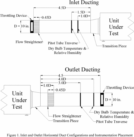
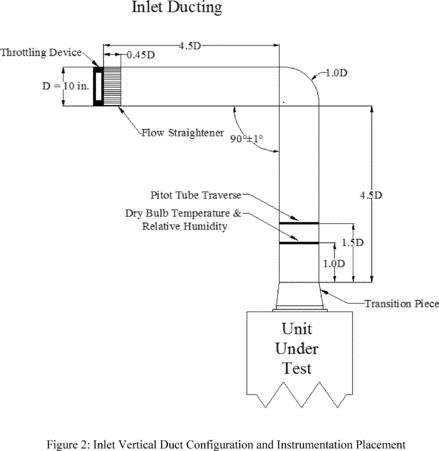
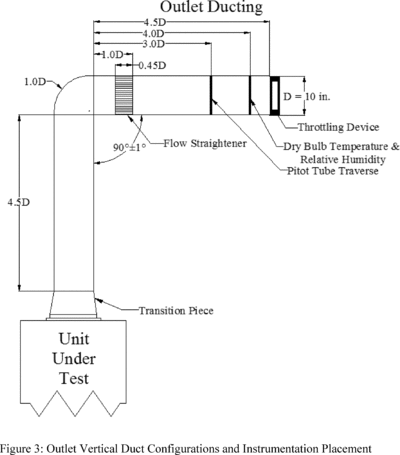
requirements specified in section 3.1.3 of this appendix and Figure
1 or Figure 3, except that the flow straightener and dry-bulb
temperature and relative humidity instruments are not required.
Maintain the external static pressure in the process air flow and
measure the external static pressure as specified in section
3.1.2.2.3.1 of this appendix.
3.1.1.2 Relative humidity instrumentation. A relative
humidity sensor with an accuracy within 1 percent relative humidity
may be used in place of an aspirating psychrometer. When using a
relative humidity sensor for testing, disregard the wet-bulb test
tolerances in Table 1 of ANSI/AHAM DH-1 (incorporated by reference,
see § 430.3), the average relative humidity over the test period
must be within 2 percent of the relative humidity setpoint, and all
individual relative humidity readings must be within 5 percent of
the relative humidity setpoint. When using a relative humidity
sensor instead of an aspirating psychrometer, use a dry-bulb
temperature sensor that meets the accuracy as required in section
4.1 of ANSI/AHAM DH-1.
3.1.1.3 Instrumentation placement. Place the aspirating
psychrometer or relative humidity and dry-bulb temperature sensors
perpendicular to, and 1 ft. in front of, the center of the process
air intake grille. When using an aspirating psychrometer, for
dehumidifiers with multiple process air intake grilles, place a
separate sampling tree perpendicular to, and 1 ft. in front of, the
center of each process air intake grille, with the samples combined
and connected to a single psychrometer using a minimal length of
insulated ducting. The psychrometer shall be used to monitor inlet
conditions of one test unit only. When using relative humidity and
dry-bulb temperature sensors, for dehumidifiers with multiple
process air intake grilles, place a relative humidity sensor and
dry-bulb temperature sensor perpendicular to, and 1 ft. in front
of, the center of each process air intake grille.
3.1.1.4 Condensate collection. If means are provided on
the dehumidifier for draining condensate away from the cabinet,
collect the condensate in a substantially closed vessel to prevent
re-evaporation and place the vessel on the weight-measuring
instrument. If no means for draining condensate away from the
cabinet are provided, disable any automatic shutoff of
dehumidification mode operation that is activated when the
collection container is full and collect any overflow in a pan.
Select a collection pan large enough to ensure that all water that
overflows from the full internal collection container during the
rating test period is captured by the collection pan. Cover the pan
as much as possible to prevent re-evaporation without impeding the
collection of overflow water. Place both the dehumidifier and the
overflow pan on the weight-measuring instrument for direct reading
of the condensate weight collected during the rating test. Do not
use any internal pump to drain the condensate into a substantially
closed vessel unless such pump operation is provided for by default
in dehumidification mode.
3.1.1.5 Control settings. If the dehumidifier has a
control setting for continuous operation in dehumidification mode,
select that control setting. Otherwise, set the controls to the
lowest available relative humidity level, and if the dehumidifier
has a user-adjustable fan speed, select the maximum fan speed
setting. Do not use any external controls for the dehumidifier
settings.
3.1.1.6 Run-in period. Perform a single run-in period
during which the compressor operates for a cumulative total of at
least 24 hours prior to dehumidification mode testing.
3.1.2 Refrigerant-desiccant dehumidifiers. The test
apparatus and instructions for testing refrigerant-desiccant
dehumidifiers in dehumidification mode must conform to the
requirements specified in Section 3, “Definitions,” Section 4,
“Instrumentation,” and Section 5, “Test Procedure,” of ANSI/AHAM
DH-1 (incorporated by reference, see § 430.3), except as
follows.
3.1.2.1 Testing configuration. Test refrigerant-desiccant
dehumidifiers with ducting attached to the process air inlet and
outlet ports and the reactivation air inlet port. The duct
configuration and components must conform to the requirements
specified in section 3.1.3 of this appendix and Figure 1 through
Figure 3. Install a cell-type airflow straightener that conforms to
the specifications in Section 5.2.1.6, “Airflow straightener”, and
Figure 6A, “Flow Straightener - Cell Type”, of ANSI/AMCA 210
(incorporated by reference, see § 430.3) in each duct consistent
with Figure 1 through Figure 3.
3.1.2.2 Instrumentation.
3.1.2.2.1 Temperature. Install dry-bulb temperature
sensors in a grid centered in the duct, with the plane of the grid
perpendicular to the axis of the duct. Determine the number and
locations of the sensors within the grid according to Section
5.3.5, “Centers of Segments - Grids,” of ANSI/ASHRAE 41.1
(incorporated by reference, see § 430.3).
3.1.2.2.2 Relative humidity. Measure relative humidity
with a duct-mounted, relative humidity sensor with an accuracy
within ±1 percent relative humidity. Place the relative humidity
sensor at the duct centerline within 1 inch of the dry-bulb
temperature grid plane.
3.1.2.2.3 Pressure. The pressure instruments used to
measure the external static pressure and velocity pressures must
have an accuracy within ±0.01 in. w.c. and a resolution of no more
than 0.01 in. w.c.
3.1.2.2.3.1 External static pressure. Measure static
pressures in each duct using pitot-static tube traverses that
conform with the specifications in Section 4.3.1, “Pitot Traverse,”
of ANSI/AMCA 210 (incorporated by reference, see § 430.3), with
pitot-static tubes that conform with the specifications in Section
4.2.2, “Pitot-Static Tube,” of ANSI/AMCA, except that only two
intersecting and perpendicular rows of pitot-static tube traverses
shall be used. Record the static pressure within the test duct as
measured at the pressure tap in the manifold of the traverses that
averages the individual static pressures at each pitot-static tube.
Calculate duct pressure losses between the unit under test and the
plane of each static pressure measurement in accordance with
section 7.5.2, “Pressure Losses,” of ANSI/AMCA 210. The external
static pressure is the difference between the measured inlet and
outlet static pressure measurements, minus the sum of the inlet and
outlet duct pressure losses. For any port with no duct attached,
use a static pressure of 0.00 in. w.c. with no duct pressure loss
in the calculation of external static pressure. During
dehumidification mode testing, the external static pressure must
equal 0.20 in. w.c. ± 0.02 in. w.c.
3.1.2.2.3.2 Velocity pressure. Measure velocity pressures
using the same pitot traverses as used for measuring external
static pressure, and which are specified in section 3.1.2.2.3.1 of
this appendix. Determine velocity pressures at each pitot-static
tube in a traverse as the difference between the pressure at the
impact pressure tap and the pressure at the static pressure tap.
Calculate volumetric flow rates in each duct in accordance with
Section 7.3.1, “Velocity Traverse,” of ANSI/AMCA 210 (incorporated
by reference, see § 430.3).
3.1.2.2.4 Weight. No weight-measuring instruments are
required.
3.1.2.3 Control settings. If the dehumidifier has a
control setting for continuous operation in dehumidification mode,
select that control setting. Otherwise, set the controls to the
lowest available relative humidity level, and if the dehumidifier
has a user-adjustable fan speed, select the maximum fan speed
setting. Do not use any external controls for the dehumidifier
settings.
3.1.2.4 Run-in period. Perform a single run-in period
during which the compressor operates for a cumulative total of at
least 24 hours prior to dehumidification mode testing.
3.1.3 Ducting for whole-home dehumidifiers. Cover and
seal with tape any port designed for intake of air from outside or
unconditioned space, other than for supplying reactivation air for
refrigerant-desiccant dehumidifiers. Use only ducting constructed
of galvanized mild steel and with a 10-inch diameter. Position
inlet and outlet ducts either horizontally or vertically to
accommodate the default dehumidifier port orientation. Install all
ducts with the axis of the section interfacing with the
dehumidifier perpendicular to plane of the collar to which each is
attached. If manufacturer-recommended collars do not measure 10
inches in diameter, use transitional pieces to connect the ducts to
the collars. The transitional pieces must not contain any
converging element that forms an angle with the duct axis greater
than 7.5 degrees or a diverging element that forms an angle with
the duct axis greater than 3.5 degrees. Install mechanical
throttling devices in each outlet duct consistent with Figure 1 and
Figure 3 to adjust the external static pressure and in the inlet
reactivation air duct for a refrigerant-desiccant dehumidifier.
Cover the ducts with thermal insulation having a minimum R value of
6 h-ft 2 − °F/Btu (1.1 m 2 − K/W). Seal seams and edges with
tape.
3.1.4 Recording and rounding. When testing either a
portable dehumidifier or a whole-home dehumidifier, record
measurements at the resolution of the test instrumentation. Record
measurements for portable dehumidifiers and whole-home
dehumidifiers other than refrigerant-desiccant dehumidifiers at
intervals no greater than 10 minutes. Record measurements for
refrigerant-desiccant dehumidifiers at intervals no greater than 1
minute. Round off calculations to the same number of significant
digits as the previous step. Round the final product capacity,
energy factor and integrated energy factor values to two decimal
places, and for whole-home dehumidifiers, round the final product
case volume to one decimal place.
3.2 Inactive mode and off mode.
3.2.1 Installation requirements. For the inactive mode
and off mode testing, install the dehumidifier in accordance with
Section 5, Paragraph 5.2 of IEC 62301 (incorporated by reference,
see § 430.3), disregarding the provisions regarding batteries and
the determination, classification, and testing of relevant
modes.
3.2.2 Electrical energy supply.
3.2.2.1 Electrical supply. For the inactive mode and off
mode testing, maintain the electrical supply voltage and frequency
indicated in Section 7.1.3, “Standard Test Voltage,” of ANSI/AHAM
DH-1 (incorporated by reference, see § 430.3). The electrical
supply frequency shall be maintained ±1 percent.
3.2.2.2 Supply voltage waveform. For the inactive mode
and off mode testing, maintain the electrical supply voltage
waveform indicated in Section 4, Paragraph 4.3.2 of IEC 62301
(incorporated by reference, see § 430.3).
3.2.3 Inactive mode, off mode, and off-cycle mode
wattmeter. The wattmeter used to measure inactive mode, off
mode, and off-cycle mode power consumption must meet the
requirements specified in Section 4, Paragraph 4.4 of IEC 62301
(incorporated by reference, see § 430.3).
3.2.4 Inactive mode and off mode ambient temperature. For
inactive mode and off mode testing, maintain room ambient air
temperature conditions as specified in Section 4, Paragraph 4.2 of
IEC 62301 (incorporated by reference, see § 430.3).
3.3 Case dimensions for whole-home dehumidifiers. Measure
case dimensions using equipment with a resolution of no more than
0.1 in.
4. Test Measurement
4.1 Dehumidification mode.
4.1.1 Portable dehumidifiers and whole-home dehumidifiers
other than refrigerant-desiccant dehumidifiers. Measure the
energy consumption in dehumidification mode, EDM, expressed in
kilowatt-hours (kWh), the average relative humidity, Ht, either as
measured using a relative humidity sensor or using the tables
provided below when using an aspirating psychrometer, and the
product capacity, Ct, expressed in pints per day (pints/day), in
accordance with the test requirements specified in Section 7,
“Capacity Test and Energy Consumption Test,” of ANSI/AHAM DH-1
(incorporated by reference, see § 430.3), except that the standard
test conditions for portable dehumidifiers must be maintained at 65
°F ± 2.0 °F dry-bulb temperature and 56.6 °F ± 1.0 °F wet-bulb
temperature, when recording conditions with an aspirating
psychrometer, or 60 percent ± 2 percent relative humidity, when
recording conditions with a relative humidity sensor. For
whole-home dehumidifiers, conditions must be maintained at 73 °F ±
2.0 °F dry-bulb temperature and 63.6 °F ± 1.0 °F wet-bulb
temperature, when recording conditions with an aspirating
psychrometer, or 60 percent ± 2 percent relative humidity, when
recording conditions with a relative humidity sensor. When using
relative humidity and dry-bulb temperature sensors, for
dehumidifiers with multiple process air intake grilles, average the
measured relative humidities and average the measured dry-bulb
temperatures to determine the overall intake air conditions.
Table 1 - Relative Humidity as a Function
of Dry-Bulb and Wet-Bulb Temperatures for Portable
Dehumidifiers
| Wet-Bulb
temperature ( °F) |
Dry-Bulb
temperature ( °F) |
| 64.5 |
64.6 |
64.7 |
64.8 |
64.9 |
65.0 |
65.1 |
65.2 |
65.3 |
65.4 |
65.5 |
| 56.3 |
60.32 |
59.94 |
59.57 |
59.17 |
58.80 |
58.42 |
58.04 |
57.67 |
57.30 |
56.93 |
56.56 |
| 56.4 |
60.77 |
60.38 |
60.00 |
59.62 |
59.24 |
58.86 |
58.48 |
58.11 |
57.73 |
57.36 |
56.99 |
| 56.5 |
61.22 |
60.83 |
60.44 |
60.06 |
59.68 |
59.30 |
58.92 |
58.54 |
58.17 |
57.80 |
57.43 |
| 56.6 |
61.66 |
61.27 |
60.89 |
60.50 |
60.12 |
59.74 |
59.36 |
58.98 |
58.60 |
58.23 |
57.86 |
| 56.7 |
62.40 |
61.72 |
61.33 |
60.95 |
60.56 |
60.18 |
59.80 |
59.42 |
59.04 |
58.67 |
58.29 |
| 56.8 |
62.56 |
62.17 |
61.78 |
61.39 |
61.00 |
60.62 |
60.24 |
59.86 |
59.48 |
59.10 |
58.73 |
| 56.9 |
63.01 |
62.62 |
62.23 |
61.84 |
61.45 |
61.06 |
60.68 |
60.30 |
59.92 |
59.54 |
59.16 |
Table 2 - Relative Humidity as a Function
of Dry-Bulb and Wet-Bulb Temperatures for Whole-Home
Dehumidifiers
| Wet-Bulb
temperature ( °F) |
Dry-Bulb
temperature ( °F) |
| 72.5 |
72.6 |
72.7 |
72.8 |
72.9 |
73.0 |
73.1 |
73.2 |
73.3 |
73.4 |
73.5 |
| 63.3 |
60.59 |
60.26 |
59.92 |
59.59 |
59.26 |
58.92 |
58.60 |
58.27 |
57.94 |
57.62 |
57.30 |
| 63.4 |
60.98 |
60.64 |
60.31 |
59.75 |
59.64 |
59.31 |
58.98 |
58.65 |
58.32 |
58.00 |
57.67 |
| 63.5 |
61.37 |
61.03 |
60.70 |
60.36 |
60.02 |
59.69 |
59.36 |
59.03 |
58.70 |
58.38 |
58.05 |
| 63.6 |
61.76 |
61.42 |
61.08 |
60.75 |
60.41 |
60.08 |
59.74 |
59.41 |
59.08 |
58.76 |
58.43 |
| 63.7 |
62.16 |
61.81 |
61.47 |
61.13 |
60.80 |
60.46 |
60.13 |
59.80 |
59.47 |
59.14 |
58.81 |
| 63.8 |
62.55 |
62.20 |
61.86 |
61.52 |
61.18 |
60.85 |
60.51 |
60.18 |
59.85 |
59.52 |
59.19 |
| 63.9 |
62.94 |
62.60 |
62.25 |
61.91 |
61.57 |
61.23 |
60.90 |
60.56 |
60.23 |
59.90 |
59.57 |
4.1.2 Refrigerant-desiccant dehumidifiers. Establish the
testing conditions set forth in section 3.1.2 of this appendix.
Measure the energy consumption, EDM, expressed in kWh, in
accordance with the test requirements specified in Section 7,
“Capacity Test and Energy Consumption Test,” of ANSI/AHAM DH-1
(incorporated by reference, see § 430.3), except that: (1)
individual readings of the standard test conditions at the air
entering the process air inlet duct and the reactivation air inlet
must be maintained within 73 °F ± 2.0 °F dry-bulb temperature and
60 percent ± 5 percent relative humidity and the arithmetic average
of the inlet test conditions over the test period shall be
maintained within 73 °F ± 0.5 °F dry-bulb temperature and 60
percent ± 2 percent relative humidity; (2) the instructions for
psychrometer placement do not apply; (3) the data recorded must
include dry-bulb temperatures, relative humidities, static
pressures, velocity pressures in each duct, volumetric air flow
rates, and the number of samples in the test period; (4) the
condensate collected during the test need not be weighed; and (5)
the calculations in Section 7.2.2, “Energy Factor Calculation,” of
ANSI/AHAM DH-1 need not be performed. To perform the calculations
in Section 7.1.7, “Calculation of Test Results,” of ANSI/AHAM DH-1:
(1) replace “Condensate collected (lb)” and “mlb”, with the weight
of condensate removed, W, as calculated in section 5.6 of this
appendix; and (2) use the recorded relative humidities rather than
the tables in section 4.1.1 of this appendix to determine average
relative humidity.
4.2 Off-cycle mode. Establish the test conditions
specified in section 3.1.1 or 3.1.2 of this appendix, but use the
wattmeter specified in section 3.2.3 of this appendix. Begin the
off-cycle mode test period immediately following the
dehumidification mode test period. Adjust the setpoint higher than
the ambient relative humidity to ensure the product will not enter
dehumidification mode and begin the test when the compressor cycles
off due to the change in setpoint. The off-cycle mode test period
shall be 2 hours in duration, during which the power consumption is
recorded at the same intervals as recorded for dehumidification
mode testing. Measure and record the average off-cycle mode power
of the dehumidifier, POC, in watts.
4.3 Inactive and off mode. Establish the testing
conditions set forth in section 3.2 of this appendix, ensuring that
the dehumidifier does not enter active mode during the test. For
dehumidifiers that take some time to enter a stable state from a
higher power state, as discussed in Section 5, Paragraph 5.1, Note
1 of IEC 62301 (incorporated by reference; see § 430.3), allow
sufficient time for the dehumidifier to reach the lower power state
before proceeding with the test measurement. Follow the test
procedure specified in Section 5, Paragraph 5.3.2 of IEC 62301 for
testing in each possible mode as described in sections 4.3.1 and
4.3.2 of this appendix.
4.3.1 If the dehumidifier has an inactive mode, as defined in
section 2.10 of this appendix, but not an off mode, as defined in
section 2.11 of this appendix, measure and record the average
inactive mode power of the dehumidifier, PIA, in watts.
4.3.2 If the dehumidifier has an off mode, as defined in section
2.11 of this appendix, measure and record the average off mode
power of the dehumidifier, POM, in watts.
4.4 Product case volume for whole-home dehumidifiers.
Measure the maximum case length, DL, in inches, the maximum case
width, DW, in inches, and the maximum height, DH, in inches,
exclusive of any duct collar attachments or other external
components.
5. Calculation of Derived Results From Test Measurements
5.1 Corrected relative humidity. Calculate the average
relative humidity, for portable and whole-home dehumidifiers,
corrected for barometric pressure variations as:
Hc,p =
Ht × [1 + 0.0083 × (29.921 −
B)]
Hc,wh =
Ht × [1 + 0.0072 × (29.921 −
B)]
Where: Hc,p = portable dehumidifier average relative humidity from
the test data in percent, corrected to the standard barometric
pressure of 29.921 in. mercury (Hg); Hc,wh = whole-home
dehumidifier average relative humidity from the test data in
percent, corrected to the standard barometric pressure of 29.921
in. Hg; Ht = average relative humidity from the test data in
percent; and B = average barometric pressure during the test period
in in. Hg.
5.2 Corrected product capacity. Calculate the product
capacity, for portable and whole-home dehumidifiers, corrected for
variations in temperature and relative humidity as:
Cr,p =
Ct + 0.0352 ×
Ct × (65 − Tt) + 0.0169 ×
Ct × (60 −
HC,p)
Cr,wh =
Ct + 0.0344 ×
Ct × (73 −
Tt) + 0.017 ×
Ct × (60 −
HC,wh) Where: Cr,p = portable dehumidifiers product capacity
in pints/day, corrected to standard rating conditions of 65 °F
dry-bulb temperature and 60 percent relative humidity; Cr,wh =
whole-home dehumidifier product capacity in pints/day, corrected to
standard rating conditions of 73 °F dry-bulb temperature and 60
percent relative humidity; Ct = product capacity determined from
test data in pints/day, as measured in section 4.1.1 of this
appendix for portable and refrigerant-only whole-home dehumidifiers
or calculated in section 5.6 of this appendix for
refrigerant-desiccant whole-home dehumidifiers; Tt = average
dry-bulb temperature during the test period in °F; HC,p = portable
dehumidifier corrected relative humidity in percent, as determined
in section 5.1 of this appendix; and HC,wh = whole-home
dehumidifier corrected relative humidity in percent, as determined
in section 5.1 of this appendix.
5.3 Annual combined low-power mode energy consumption.
Calculate the annual combined low-power mode energy consumption for
dehumidifiers, ETLP, expressed in kWh per year:
ETLP = [(PIO × SIO) + (POC × SOC)] × K Where: PIO = PIA,
dehumidifier inactive mode power, or POM, dehumidifier off mode
power in watts, as measured in section 4.3 of this appendix; POC =
dehumidifier off-cycle mode power in watts, as measured in section
4.2 of this appendix; SIO = 1,840.5 dehumidifier inactive mode or
off mode annual hours; SOC = 1,840.5 dehumidifier off-cycle mode
annual hours; and K = 0.001 kWh/Wh conversion factor for watt-hours
to kWh.
5.4 Integrated energy factor. Calculate the integrated
energy factor, IEF, expressed in L/kWh, rounded to two decimal
places, according to the following:
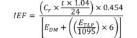
Where: Cr
= corrected product capacity in pints per day, as determined in
section 5.2 of this appendix; t = test duration in hours; EDM =
energy consumption during the 6-hour dehumidification mode test in
kWh, as measured in section 4.1 of this appendix; ETLP = annual
combined low-power mode energy consumption in kWh per year, as
calculated in section 5.3 of this appendix; 1,095 =
dehumidification mode annual hours, used to convert ETLP to
combined low-power mode energy consumption per hour of
dehumidification mode; 6 = hours per dehumidification mode test,
used to convert annual combined low-power mode energy consumption
per hour of dehumidification mode for integration with
dehumidification mode energy consumption; 1.04 = the density of
water in pounds per pint; 0.454 = the liters of water per pound of
water; and 24 = the number of hours per day.
5.5 Absolute humidity for refrigerant-desiccant
dehumidifiers. Calculate the absolute humidity of the air
entering and leaving the refrigerant-desiccant dehumidifier in the
process air stream, expressed in pounds of water per cubic foot of
air, according to the following set of equations.
5.5.1 Temperature in Kelvin. The air dry-bulb temperature, in
Kelvin, is:
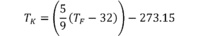
Where: TF
= the measured dry-bulb temperature of the air in °F.
5.5.2 Water saturation pressure. The water saturation pressure,
expressed in kilopascals (kPa), is:

Where: TK
= the calculated dry-bulb temperature of the air in K, calculated
in section 5.5.1 of this appendix.
5.5.3 Vapor pressure. The water vapor pressure, expressed in
kilopascals (kPa), is:

Where: RH
= percent relative humidity during the rating test period; and Pws
= water vapor saturation pressure in kPa, calculated in section
5.5.2 of this appendix.
5.5.4 Mixing humidity ratio. The mixing humidity ratio, the mass
of water per mass of dry air, is:

Where: Pw
= water vapor pressure in kPa, calculated in section 5.5.3 of this
appendix; P = measured ambient barometric pressure in in. Hg; 3.386
= the conversion factor from in. Hg to kPa; and 0.62198 = the ratio
of the molecular weight of water to the molecular weight of dry
air.
5.5.5 Specific volume. The specific volume, expressed in feet
cubed per pounds of dry air, is:
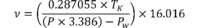
Where: TK
= dry-bulb temperature of the air in K, as calculated in section
5.5.1 of this appendix; P = measured ambient barometric pressure in
in. Hg; Pw = water vapor pressure in kPa, calculated in section
5.5.3 of this appendix; 0.287055 = the specific gas constant for
dry air in kPa times cubic meter per kg per K; 3.386 = the
conversion factor from in. Hg to kPa; and 16.016 = the conversion
factor from cubic meters per kilogram to cubic feet per pound.
5.5.6 Absolute humidity. The absolute humidity, expressed in
pounds of water per cubic foot of air, is:

Where: HR
= the mixing humidity ratio, the mass of water per mass of dry air,
as calculated in section 5.5.4 of this appendix; and ν = the
specific volume in cubic feet per pound of dry air, as calculated
in section 5.5.5 of this appendix.
5.6 Product capacity for refrigerant-desiccant
dehumidifiers. The weight of water removed during the test
period, W, expressed in pounds is:
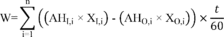
Where: n
= number of samples during the test period in section 4.1.1.2 of
this appendix; AHI,i = absolute humidity of the process air on the
inlet side of the unit in pounds of water per cubic foot of dry
air, as calculated for sample
i in section 5.5.6 of this
appendix; XI,i = volumetric flow rate of the process air on the
inlet side of the unit in cubic feet per minute, measured for
sample
i in section 4.1.1.2 of this appendix. Calculate the
volumetric flow rate in accordance with Section 7.3, “Fan airflow
rate at test conditions,” of ANSI/AMCA 210 (incorporated by
reference, see § 430.3); AHO,i = absolute humidity of the process
air on the outlet side of the unit in pounds of water per cubic
foot of dry air, as calculated for sample
i in section 5.5.6
of this appendix; XO,i = volumetric flow rate of the process air on
the outlet side of the unit in cubic feet per minute, measured for
sample
i in section 4.1.1.2 of this appendix. Calculate the
volumetric flow rate in accordance with Section 7.3, “Fan airflow
rate at test conditions,” of ANSI/AMCA 210 (incorporated by
reference, see § 430.3); t = time interval in seconds between
samples, with a maximum of 60; and 60 = conversion from minutes to
seconds.
The capacity, Ct, expressed in pints/day, is:

Where: 24
= number of hours per day; 1.04 = density of water in pounds per
pint; and T = total test period time in hours.
Then correct the product capacity, Cr,wh, according to section
5.2 of this appendix.
5.7 Product case volume for whole-home dehumidifiers. The
product case volume, V, in cubic feet, is:

Where: DL
= product case length in inches, measured in section 4.4 of this
appendix; DW = product case width in inches, measured in section
4.4 of this appendix; DH = product case height in inches, measured
in section 4.4 of this appendix; and 1,728 = conversion from cubic
inches to cubic feet. [80 FR 45826, July 31, 2015]