Title 10
PART 430 APPENDIX E
| Item measured | Instrument accuracy | Instrument precision |
|---|---|---|
| Gas pressure | ±0.1 inch of water column (±0.025 kPa) | ±0.05 inch of water column (±0.012 kPa). |
| Atmospheric pressure | ±0.1 inch of mercury column (±0.34 kPa) | ±0.05 inch of mercury column (±0.17 kPa). |
| Water pressure | ±1.0 pounds per square inch (±6.9 kPa) | ±0.50 pounds per square inch (±3.45 kPa). |
3.2 Temperature Measurement
3.2.1 Measurement. Temperature measurements shall be made in accordance with the Standard Method for Temperature Measurement, ASHRAE 41.1-1986 (incorporated by reference, see § 430.3).
3.2.2 Accuracy and Precision. The accuracy and precision of the instruments, including their associated readout devices, shall be within the following limits:
| Item measured | Instrument accuracy | Instrument precision |
|---|---|---|
| Air dry bulb temperature | ±0.2 °F (±0.1 °C) | ±0.1 °F (±0.06 °C). |
| Air wet bulb temperature | ±0.2 °F (±0.1 °C) | ±0.1 °F (±0.06 °C). |
| Inlet and outlet water temperatures | ±0.2 °F (±0.1 °C) | ±0.1 °F (±0.06 °C). |
| Storage tank temperatures | ±0.5 °F (±0.3 °C) | ±0.25 °F (±0.14 °C). |
3.2.3 Scale Division. In no case shall the smallest scale division of the instrument or instrument system exceed 2 times the specified precision.
3.2.4 Temperature Difference Temperature difference between the entering and leaving water may be measured with any of the following:
a. A thermopile b. Calibrated resistance thermometers c. Precision thermometers d. Calibrated thermistors e. Calibrated thermocouples f. Quartz thermometers3.2.5 Thermopile Construction. If a thermopile is used, it shall be made from calibrated thermocouple wire taken from a single spool. Extension wires to the recording device shall also be made from that same spool.
3.2.6 Time Constant. The time constant of the instruments used to measure the inlet and outlet water temperatures shall be no greater than 2 seconds.
3.3 Liquid Flow Rate Measurement. The accuracy of the liquid flow rate measurement, using the calibration if furnished, shall be equal to or less than ±1% of the measured value in mass units per unit time.
3.4 Electrical Energy. The electrical energy used shall be measured with an instrument and associated readout device that is accurate within ±0.5% of the reading.
3.5 Fossil Fuels. The quantity of fuel used by the water heater shall be measured with an instrument and associated readout device that is accurate within ±1% of the reading.
3.6 Mass Measurements. For mass measurements greater than or equal to 10 pounds (4.5 kg), a scale that is accurate within ±0.5% of the reading shall be used to make the measurement. For mass measurements less than 10 pounds (4.5 kg), the scale shall provide a measurement that is accurate within ±0.1 pound (0.045 kg).
3.7 Heating Value. The higher heating value of the natural gas, propane, or fuel oil shall be measured with an instrument and associated readout device that is accurate within ±1% of the reading. The heating values of natural gas and propane must be corrected from those reported at standard temperature and pressure conditions to provide the heating value at the temperature and pressure measured at the fuel meter.
3.8 Time. The elapsed time measurements shall be measured with an instrument that is accurate within ±0.5 seconds per hour.
3.9 Volume. Volume measurements shall be measured with an accuracy of ±2% of the total volume.
3.10 Relative Humidity. If a relative humidity (RH) transducer is used to measure the relative humidity of the surrounding air while testing heat pump water heaters, the relative humidity shall be measured with an accuracy of ±1.5% RH.
4. Installation4.1 Water Heater Mounting. A water heater designed to be freestanding shall be placed on a 3/4 inch (2 cm) thick plywood platform supported by three 2×4 inch (5 cm×10 cm) runners. If the water heater is not approved for installation on combustible flooring, suitable non-combustible material shall be placed between the water heater and the platform. Counter-top water heaters shall be placed against a simulated wall section. Wall-mounted water heaters shall be supported on a simulated wall in accordance with the manufacturer-published installation instructions. When a simulated wall is used, the construction shall be 2×4 inch (5 cm×10 cm) studs, faced with 3/4 inch (2 cm) plywood. For heat pump water heaters not delivered as a single package, the units shall be connected in accordance with the manufacturer-published installation instructions and the overall system shall be placed on the above-described plywood platform. If installation instructions are not provided by the heat pump manufacturer, uninsulated 8 foot (2.4 m) long connecting hoses having an inside diameter of 5/8 inch (1.6 cm) shall be used to connect the storage tank and the heat pump water heater. The testing of the water heater shall occur in an area that is protected from drafts of more than 50 ft/min (0.25 m/s) from room ventilation registers, windows, or other external sources of air movement.
4.2 Water Supply. Connect the water heater to a water supply capable of delivering water at conditions as specified in sections 2.3 and 2.6 of this appendix.
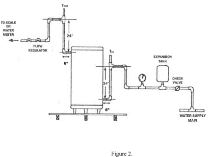
4.3 Water Inlet and Outlet Configuration. For freestanding water heaters that are taller than 36 inches (91.4 cm), inlet and outlet piping connections shall be configured in a manner consistent with Figures 1 and 2 of section 6.4.6 of this appendix. Inlet and outlet piping connections for wall-mounted water heaters shall be consistent with Figure 3 of section 6.4.6 of this appendix. For freestanding water heaters that are 36 inches or less in height and not supplied as part of a counter-top enclosure (commonly referred to as an under-the-counter model), inlet and outlet piping shall be installed in a manner consistent with Figures 4, 5, or 6 of section 6.4.6 of this appendix. For water heaters that are supplied with a counter-top enclosure, inlet and outlet piping shall be made in a manner consistent with Figures 7a and 7b of section 6.4.6 of this appendix, respectively. The vertical piping noted in Figures 7a and 7b shall be located (whether inside the enclosure or along the outside in a recessed channel) in accordance with the manufacturer-published installation instructions.
All dimensions noted in Figures 1 through 7 of section 6.4.6 of this appendix must be achieved. All piping between the water heater and inlet and outlet temperature sensors, noted as TIN and TOUT in the figures, shall be Type “L” hard copper having the same diameter as the connections on the water heater. Unions may be used to facilitate installation and removal of the piping arrangements. Install a pressure gauge and diaphragm expansion tank in the supply water piping at a location upstream of the inlet temperature sensor. Install an appropriately rated pressure and temperature relief valve on all water heaters at the port specified by the manufacturer. Discharge piping for the relief valve must be non-metallic. If heat traps, piping insulation, or pressure relief valve insulation are supplied with the water heater, they must be installed for testing. Except when using a simulated wall, provide sufficient clearance such that none of the piping contacts other surfaces in the test room.
4.4 Fuel and/or Electrical Power and Energy Consumption. Install one or more instruments that measure, as appropriate, the quantity and rate of electrical energy and/or fossil fuel consumption in accordance with section 3 of this appendix.
4.5 Internal Storage Tank Temperature Measurements. For water heaters with rated storage volumes greater than or equal to 20 gallons, install six temperature measurement sensors inside the water heater tank with a vertical distance of at least 4 inches (100 mm) between successive sensors. For water heaters with rated storage volumes between 2 and 20 gallons, install three temperature measurement sensors inside the water heater tank. Position a temperature sensor at the vertical midpoint of each of the six equal volume nodes within a tank larger than 20 gallons or the three equal volume nodes within a tank between 2 and 20 gallons. Nodes designate the equal volumes used to evenly partition the total volume of the tank. As much as is possible, the temperature sensor should be positioned away from any heating elements, anodic protective devices, tank walls, and flue pipe walls. If the tank cannot accommodate six temperature sensors and meet the installation requirements specified above, install the maximum number of sensors that comply with the installation requirements. Install the temperature sensors through: (1) The anodic device opening; (2) the relief valve opening; or (3) the hot water outlet. If installed through the relief valve opening or the hot water outlet, a tee fitting or outlet piping, as applicable, must be installed as close as possible to its original location. If the relief valve temperature sensor is relocated, and it no longer extends into the top of the tank, install a substitute relief valve that has a sensing element that can reach into the tank. If the hot water outlet includes a heat trap, install the heat trap on top of the tee fitting. Cover any added fittings with thermal insulation having an R value between 4 and 8 h·ft 2· °F/Btu (0.7 and 1.4 m 2· °C/W).
4.6 Ambient Air Temperature Measurement. Install an ambient air temperature sensor at the vertical mid-point of the water heater and approximately 2 feet (610 mm) from the surface of the water heater. Shield the sensor against radiation.
4.7 Inlet and Outlet Water Temperature Measurements. Install temperature sensors in the cold-water inlet pipe and hot-water outlet pipe as shown in Figures 1, 2, 3, 4, 5, 6, 7a, and 7b of section 6.4.6 of this appendix, as applicable.
4.8 Flow Control. Install a valve or valves to provide flow as specified in sections 5.3 and 5.4 of this appendix.
4.9 Flue Requirements.
4.9.1 Gas-Fired Water Heaters. Establish a natural draft in the following manner. For gas-fired water heaters with a vertically discharging draft hood outlet, connect to the draft hood outlet a 5-foot (1.5-meter) vertical vent pipe extension with a diameter equal to the largest flue collar size of the draft hood. For gas-fired water heaters with a horizontally discharging draft hood outlet, connect to the draft hood outlet a 90-degree elbow with a diameter equal to the largest flue collar size of the draft hood, connect a 5-foot (1.5-meter) length of vent pipe to that elbow, and orient the vent pipe to discharge vertically upward. Install direct-vent gas-fired water heaters with venting equipment specified in the manufacturer's instructions using the minimum vertical and horizontal lengths of vent pipe recommended by the manufacturer.
4.9.2 Oil-Fired Water Heaters. Establish a draft at the flue collar at the value specified in the manufacturer's instructions. Establish the draft by using a sufficient length of vent pipe connected to the water heater flue outlet, and directed vertically upward. For an oil-fired water heater with a horizontally discharging draft hood outlet, connect to the draft hood outlet a 90-degree elbow with a diameter equal to the largest flue collar size of the draft hood, connect to the elbow fitting a length of vent pipe sufficient to establish the draft, and orient the vent pipe to discharge vertically upward. Direct-vent oil-fired water heaters should be installed with venting equipment as specified in the manufacturer's instructions, using the minimum vertical and horizontal lengths of vent pipe recommended by the manufacturer.
5. Test Procedures5.1 Operational Mode Selection. For water heaters that allow for multiple user-selected operational modes, all procedures specified in this appendix shall be carried out with the water heater in the same operational mode (i.e., only one mode). This operational mode shall be the default mode (or similarly-named, suggested mode for normal operation) as defined by the manufacturer in its product literature for giving selection guidance to the consumer. For heat pump water heaters, if a default mode is not defined in the product literature, each test shall be conducted under an operational mode in which both the heat pump and any electric resistance backup heating element(s) are activated by the unit's control scheme, and which can achieve the internal storage tank temperature specified in this test procedure; if multiple operational modes meet these criteria, the water heater shall be tested under the most energy-intensive mode. If no default mode is specified and the unit does not offer an operational mode that utilizes both the heat pump and the electric resistance backup heating element(s), the first-hour rating test and the simulated-use test shall be tested in heat-pump-only mode. For other types of water heaters where a default mode is not specified, test the unit in all modes and rate the unit using the results of the most energy-intensive mode.
5.2 Water Heater Preparation.
5.2.1 Determination of Storage Tank Volume. For water heaters with a rated storage volume greater than or equal to 2 gallons, determine the storage capacity, Vst, of the water heater under test, in gallons (liters), by subtracting the tare weight - measured while the tank is empty - from the gross weight of the storage tank when completely filled with water (with all air eliminated and line pressure applied as described in section 2.5 of this appendix) and dividing the resulting net weight by the density of water at the measured temperature.
5.2.2 Setting the Outlet Discharge Temperature.
5.2.2.1 Flow-Activated Water Heaters, including certain instantaneous water heaters and certain storage-type water heaters. Initiate normal operation of the water heater at the full input rating for electric water heaters and at the maximum firing rate specified by the manufacturer for gas or oil water heaters. Monitor the discharge water temperature and set to a value of 125 °F ±5 °F (51.7 °C ±2.8 °C) in accordance with the manufacturer's instructions. If the water heater is not capable of providing this discharge temperature when the flow rate is 1.7 gallons ±0.25 gallons per minute (6.4 liters ±0.95 liters per minute), then adjust the flow rate as necessary to achieve the specified discharge water temperature. Once the proper temperature control setting is achieved, the setting must remain fixed for the duration of the maximum GPM test and the simulated-use test.
5.2.2.2 Storage-Type Water Heaters that Are Not Flow-Activated.
5.2.2.2.1 Tanks with a Single Temperature Controller.
5.2.2.2.1.1 Water Heaters with Rated Volumes Less than 20 Gallons. Starting with a tank at the supply water temperature, initiate normal operation of the water heater. After cut-out, initiate a draw from the water heater at a flow rate of 1.0 gallon ±0.25 gallons per minute (3.8 liters ±0.95 liters per minute) for 2 minutes. Starting 15 seconds after commencement of draw, record the outlet temperature at 15-second intervals until the end of the 2-minute period. Determine whether the maximum outlet temperature is within the range of 125 °F ±5 °F (51.7 °C ±2.8 °C). If not, turn off the water heater, adjust the temperature controller, and then drain and refill the tank with supply water. Then, once again, initiate normal operation of the water heater, and repeat the 2-minute outlet temperature test following cut-out. Repeat this sequence until the maximum outlet temperature during the 2-minute test is within 125 °F ±5 °F (51.7 °C ±2.8 °C). Once the proper temperature control setting is achieved, the setting must remain fixed for the duration of the first-hour rating test and the simulated-use test such that a second identical simulated-use test run immediately following the one specified in section 5.4 would result in average delivered water temperatures that are within the bounds specified in section 2.4 of this appendix.
5.2.2.2.1.2 Water Heaters with Rated Volumes Greater than or Equal to 20 Gallons. Starting with a tank at the supply water temperature, initiate normal operation of the water heater. After cut-out, initiate a draw from the water heater at a flow rate of 1.7 gallons ±0.25 gallons per minute (6.4 liters ±0.95 liters per minute) for 5 minutes. Starting 15 seconds after commencement of draw, record the outlet temperature at 15-second intervals until the end of the 5-minute period. Determine whether the maximum outlet temperature is within the range of 125 °F ±5 °F (51.7 °C ±2.8 °C). If not, turn off the water heater, adjust the temperature controller, and then drain and refill the tank with supply water. Then, once again, initiate normal operation of the water heater, and repeat the 5-minute outlet temperature test following cut-out. Repeat this sequence until the maximum outlet temperature during the 5-minute test is within of 125 °F ±5 °F (51.7 °C ±2.8 °C). Once the proper temperature control setting is achieved, the setting must remain fixed for the duration of the first-hour rating test and the simulated-use test such that a second identical simulated-use test run immediately following the one specified in section 5.4 would result in average delivered water temperatures that are within the bounds specified in section 2.4 of this appendix.
5.2.2.2.2 Tanks with Two or More Temperature Controllers. Verify the temperature controller set-point while removing water in accordance with the procedure set forth for the first-hour rating test in section 5.3.3 of this appendix. The following criteria must be met to ensure that all temperature controllers are set to deliver water at 125 °F ±5 °F (51.7 °C ±2.8 °C):
(a) At least 50 percent of the water drawn during the first draw of the first-hour rating test procedure shall be delivered at a temperature of 125 °F ±5 °F (51.7 °C ±2.8 °C).
(b) No water is delivered above 130 °F (54.4 °C) during first-hour rating test.
(c) The delivery temperature measured 15 seconds after commencement of each draw begun prior to an elapsed time of 60 minutes from the start of the test shall be at 125 °F ±5 °F (51.7 °C ±2.8 °C).
If these conditions are not met, turn off the water heater, adjust the temperature controllers, and then drain and refill the tank with supply water. Repeat the procedure described at the start of section 5.2.2.2.2 until the criteria for setting the temperature controllers is met.
If the conditions stated above are met, the data obtained during the process of verifying the temperature control set-points may be used in determining the first-hour rating provided that all other conditions and methods required in sections 2 and 5.2.4 in preparing the water heater were followed.
5.2.3 Power Input Determination. For all water heaters except electric types, initiate normal operation (as described in section 5.1) and determine the power input, P, to the main burners (including pilot light power, if any) after 15 minutes of operation. If the water heater is equipped with a gas appliance pressure regulator, the regulator outlet pressure shall be set within ±10% of that recommended by the manufacturer. For oil-fired water heaters, the fuel pump pressure shall be within ±10% of the manufacturer's specified pump pressure. Adjust all burners to achieve an hourly Btu (kJ) rating that is within ±2% of the value specified by the manufacturer. For an oil-fired water heater, adjust the burner to give a CO2 reading recommended by the manufacturer and an hourly Btu (kJ) rating that is within ±2% of that specified by the manufacturer. Smoke in the flue may not exceed No. 1 smoke as measured by the procedure in ASTM D2156 (incorporated by reference, see § 430.3).
5.2.4 Soak-In Period for Water Heaters with Rated Storage Volumes Greater than or Equal to 2 Gallons. For storage-type water heaters and instantaneous water heaters having greater than 2 gallons (7.6 liters) of storage (including heat pump water heaters having greater than 2 gallons of storage), the water heater must sit filled with water and without any draws taking place for at least 12 hours after initially being energized so as to achieve the nominal temperature set-point within the tank and with the unit connected to a power source.
5.3 Delivery Capacity Tests.
5.3.1 General. For flow-activated water heaters, conduct the maximum GPM test, as described in section 5.3.2, Maximum GPM Rating Test for Flow-Activated Water Heaters, of this appendix. For all other water heaters, conduct the first-hour rating test as described in section 5.3.3 of this appendix.
5.3.2 Maximum GPM Rating Test for Flow-Activated Water Heaters. Establish normal water heater operation at the full input rate for electric water heaters and at the maximum firing rate for gas or oil water heaters with the discharge water temperature set in accordance with section 5.2.2.1 of this appendix.
For this 10-minute test, either collect the withdrawn water for later measurement of the total mass removed or use a water meter to directly measure the water volume removed. Initiate water flow through the water heater and record the inlet and outlet water temperatures beginning 15 seconds after the start of the test and at subsequent 5-second intervals throughout the duration of the test. At the end of 10 minutes, turn off the water. Determine and record the mass of water collected, M10m, in pounds (kilograms), or the volume of water, V10m, in gallons (liters).
5.3.3 First-Hour Rating Test.
5.3.3.1 General. During hot water draws for water heaters with rated storage volumes greater than or equal to 20 gallons, remove water at a rate of 3.0 ±0.25 gallons per minute (11.4 ±0.95 liters per minute). During hot water draws for storage-type water heaters with rated storage volumes below 20 gallons, remove water at a rate of 1.0 ±0.25 gallon per minute (3.8 ±0.95 liters per minute). Collect the water in a container that is large enough to hold the volume removed during an individual draw and is suitable for weighing at the termination of each draw to determine the total volume of water withdrawn. As an alternative to collecting the water, a water meter may be used to directly measure the water volume(s) withdrawn.
5.3.3.2 Draw Initiation Criteria. Begin the first-hour rating test by starting a draw on the storage-type water heater. After completion of this first draw, initiate successive draws based on the following criteria. For gas-fired and oil-fired water heaters, initiate successive draws when the temperature controller acts to reduce the supply of fuel to the main burner. For electric water heaters having a single element or multiple elements that all operate simultaneously, initiate successive draws when the temperature controller acts to reduce the electrical input supplied to the element(s). For electric water heaters having two or more elements that do not operate simultaneously, initiate successive draws when the applicable temperature controller acts to reduce the electrical input to the energized element located vertically highest in the storage tank. For heat pump water heaters that do not use supplemental, resistive heating, initiate successive draws immediately after the electrical input to the compressor is reduced by the action of the water heater's temperature controller. For heat pump water heaters that use supplemental resistive heating, initiate successive draws immediately after the electrical input to the first of either the compressor or the vertically highest resistive element is reduced by the action of the applicable water heater temperature controller. This draw initiation criterion for heat pump water heaters that use supplemental resistive heating, however, shall only apply when the water located above the thermostat at cut-out is heated to 125 °F ±5 °F (51.7 °C ±2.8 °C). If this criterion is not met, then the next draw should be initiated once the heat pump compressor cuts out.
5.3.3.3 Test Sequence. Establish normal water heater operation. If the water heater is not presently operating, initiate a draw. The draw may be terminated any time after cut-in occurs. After cut-out occurs (i.e., all temperature controllers are satisfied), record the internal storage tank temperature at each sensor described in section 4.5 of this appendix every one minute, and determine the mean tank temperature by averaging the values from these sensors.
Initiate a draw after a maximum mean tank temperature (the maximum of the mean temperatures of the individual sensors) has been observed following a cut-out. Record the time when the draw is initiated and designate it as an elapsed time of zero (τ* = 0). (The superscript * is used to denote variables pertaining to the first-hour rating test). Record the outlet water temperature beginning 15 seconds after the draw is initiated and at 5-second intervals thereafter until the draw is terminated. Determine the maximum outlet temperature that occurs during this first draw and record it as T*max,1. For the duration of this first draw and all successive draws, in addition, monitor the inlet temperature to the water heater to ensure that the required 58 °F ±2 °F (14.4 °C ±1.1 °C) test condition is met. Terminate the hot water draw when the outlet temperature decreases to T*max,1 − 15 °F (T*max,1 − 8.3 °C). (Note, if the outlet temperature does not decrease to T*max,1 − 15 °F (T*max,1 − 8.3 °C) during the draw, then hot water would be drawn continuously for the duration of the test. In this instance, the test would end when the temperature decreases to T*max,1− 15 °F (T*max,1 − 8.3 °C) after the electrical power and/or fuel supplied to the water heater is shut off, as described in the following paragraphs.) Record this temperature as T*min,1. Following draw termination, determine the average outlet water temperature and the mass or volume removed during this first draw and record them as T *del,i and M*1 or V*1, respectively.
Initiate a second and, if applicable, successive draw(s) each time the applicable draw initiation criteria described in section 5.3.3.2 are satisfied. As required for the first draw, record the outlet water temperature 15 seconds after initiating each draw and at 5-second intervals thereafter until the draw is terminated. Determine the maximum outlet temperature that occurs during each draw and record it as T*max,i, where the subscript i refers to the draw number. Terminate each hot water draw when the outlet temperature decreases to T*max,i − 15 °F (T*max,i − 8.3 °C). Record this temperature as T*min,i. Calculate and record the average outlet temperature and the mass or volume removed during each draw (T *del,i and M*i or V*i, respectively). Continue this sequence of draw and recovery until one hour after the start of the test, then shut off the electrical power and/or fuel supplied to the water heater.
If a draw is occurring at one hour from the start of the test, continue this draw until the outlet temperature decreases to T*max,n − 15 °F (T*max,n − 8.3 °C), at which time the draw shall be immediately terminated. (The subscript n shall be used to denote measurements associated with the final draw.) If a draw is not occurring one hour after the start of the test, initiate a final draw at one hour, regardless of whether the criteria described in section 5.3.3.2 of this appendix are satisfied. This draw shall proceed for a minimum of 30 seconds and shall terminate when the outlet temperature first indicates a value less than or equal to the cut-off temperature used for the previous draw (T*min,n−1). If an outlet temperature greater than T*min,n−1 is not measured within 30 seconds of initiation of the draw, zero additional credit shall be given towards first-hour rating (i.e., M*n = 0 or V*n = 0) based on the final draw. After the final draw is terminated, calculate and record the average outlet temperature and the mass or volume removed during the final draw (T *del,n and M*n or V*n, respectively).
5.4 24-Hour Simulated Use Test.
5.4.1 Selection of Draw Pattern. The water heater will be tested under a draw profile that depends upon the first-hour rating obtained following the test prescribed in section 5.3.3 of this appendix, or the maximum GPM rating obtained following the test prescribed in section 5.3.2 of this appendix, whichever is applicable. For water heaters that have been tested according to the first-hour rating procedure, one of four different patterns shall be applied based on the measured first-hour rating, as shown in Table I of this section. For water heater that have been tested according to the maximum GPM rating procedure, one of four different patterns shall be applied based on the maximum GPM, as shown in Table II of this section.
Table I - Draw Pattern To Be Used Based on First-Hour Rating
| First-hour rating greater than or equal to: | ... and first-hour rating less than: | Draw pattern to be used in simulated-use test |
|---|---|---|
| 0 gallons | 18 gallons | Very-Small-Usage (Table III.1). |
| 18 gallons | 51 gallons | Low-Usage (Table III.2). |
| 51 gallons | 75 gallons | Medium-Usage (Table III.3). |
| 75 gallons | No upper limit | High-Usage (Table III.4). |
Table II - Draw Pattern To Be Used Based on Maximum GPM Rating
| Maximum GPM rating greater than or equal to: | and maximum GPM rating less than: | Draw pattern to be used in simulated-use test |
|---|---|---|
| 0 gallons/minute | 1.7 gallons/minute | Very-Small-Usage (Table III.1). |
| 1.7 gallons/minute | 2.8 gallons/minute | Low-Usage (Table III.2). |
| 2.8 gallons/minute | 4 gallons/minute | Medium-Usage (Table III.3). |
| 4 gallons/minute | No upper limit | High-Usage (Table III.4). |
The draw patterns are provided in Tables III.1 through III.4 in section 5.5 of this appendix. Use the appropriate draw pattern when conducting the test sequence provided in section 5.4.2 of this appendix for water heaters with rated storage volumes greater than or equal to 2 gallons or section 5.4.3 of this appendix for water heaters with rated storage volumes less than 2 gallons.
5.4.2 Test Sequence for Water Heaters with Rated Storage Volumes Greater Than or Equal to 2 Gallons. If the water heater is turned off, fill the water heater with supply water and maintain supply water pressure as described in section 2.6 of this appendix. Turn on the water heater and associated heat pump unit, if present. If turned on in this fashion, the soak-in period described in section 5.2.4 of this appendix shall be implemented. If the water heater has undergone a first-hour rating test prior to conduct of the simulated-use test, allow the water heater to fully recover after completion of that test such that the main burner, heating elements, or heat pump compressor of the water heater are no longer raising the temperature of the stored water. In all cases, the water heater shall sit idle for 1 hour prior to the start of the 24-hour test; during which time no water is drawn from the unit and there is no energy input to the main heating elements, heat pump compressor, and/or burners. At the end of this period, the 24-hour simulated-use test will begin.
At the start of the 24-hour test, record the mean tank temperature (T 0), and the electrical and/or fuel measurement readings, as appropriate. Begin the 24-hour simulated use test by withdrawing the volume specified in the appropriate table in section 5.5 of this appendix (i.e., Table III.1, Table III.2, Table III.3, or Table III.4, depending on the first-hour rating or maximum GPM rating) for the first draw at the flow rate specified in the applicable table. Record the time when this first draw is initiated and assign it as the test elapsed time (τ) of zero (0). Record the average storage tank and ambient temperature every minute throughout the 24-hour simulated-use test. At the elapsed times specified in the applicable draw pattern table in section 5.5 of this appendix for a particular draw pattern, initiate additional draws pursuant to the draw pattern, removing the volume of hot water at the prescribed flow rate specified by the table. The maximum allowable deviation from the specified volume of water removed for any single draw taken at a nominal flow rate of 1 GPM or 1.7 GPM is ±0.1 gallons (±0.4 liters). The maximum allowable deviation from the specified volume of water removed for any single draw taken at a nominal flow rate of 3 GPM is ±0.25 gallons (0.9 liters). The quantity of water withdrawn during the last draw shall be increased or decreased as necessary such that the total volume of water withdrawn equals the prescribed daily amount for that draw pattern ±1.0 gallon (±3.8 liters). If this adjustment to the volume drawn during the last draw results in no draw taking place, the test is considered invalid.
All draws during the 24-hour simulated-use test shall be made at the flow rates specified in the applicable draw pattern table in section 5.5 of this appendix, within a tolerance of ±0.25 gallons per minute (±0. 9 liters per minute). Measurements of the inlet and outlet temperatures shall be made 5 seconds after the draw is initiated and at every subsequent 3-second interval throughout the duration of each draw. Calculate and record the mean of the hot water discharge temperature and the cold water inlet temperature for each draw T del,i and T in,i). Determine and record the net mass or volume removed (Mi or Vi), as appropriate, after each draw.
At the end of the first recovery period following the first draw, which may extend beyond subsequent draws, record the maximum mean tank temperature observed after cut-out, T max,1, and the energy consumed by an electric resistance, gas, or oil-fired water heater (including electrical energy), from the beginning of the test, Qr. For heat pump water heaters, the total energy consumed during the first recovery by the heat pump (including compressor, fan, controls, pump, etc.) and, if applicable, by the resistive element(s) shall be recorded as Qr.
The start of the portion of the test during which the standby loss coefficient is determined depends upon whether the unit has fully recovered from the first draw cluster. If a recovery is occurring at or within five minutes of the end of the final draw in the first draw cluster, as identified in the applicable draw pattern table in section 5.5 of this appendix, then the standby period starts when a maximum average tank temperature is observed starting five minutes after the end of the recovery period that follows that draw. If a recovery does not occur at or within five minutes of the end of the final draw in the first draw cluster, as identified in the applicable draw pattern table in section 5.5 of this appendix, then the standby period starts five minutes after the end of that draw. Determine and record the total electrical energy and/or fossil fuel consumed from the beginning of the test to the start of the standby period, Qsu,0.
In preparation for determining the energy consumed during standby, record the reading given on the electrical energy (watt-hour) meter, the gas meter, and/or the scale used to determine oil consumption, as appropriate. Record the mean tank temperature at the start of the standby period as T su,0. At 1-minute intervals, record the mean tank temperature and the electric and/or fuel instrument readings until the next draw is initiated. Just prior to initiation of the next draw, record the mean tank temperature as T su,f. If the water heater is undergoing recovery when the next draw is initiated, record the mean tank temperature T su,f at the minute prior to the start of the recovery. The time at which this value occurs is the end of the standby period. Determine the total electrical energy and/or fossil fuel energy consumption from the beginning of the test to this time and record as Qsu,f. Record the time interval between the start of the standby period and the end of the standby period as τstby,1. Record the time during which water is not being withdrawn from the water heater during the entire 24-hour period as τstby,2.
In the event that the recovery period continues from the end of the last draw of the first draw cluster until the subsequent draw, the standby period will start after the end of the first recovery period after the last draw of the simulated-use test, when the temperature reaches the maximum average tank temperature, though no sooner than five minutes after the end of this recovery period. The standby period shall last eight hours, so testing will extend beyond the 24-hour duration of the simulated-use test. Determine and record the total electrical energy and/or fossil fuel consumed from the beginning of the simulated-use test to the start of the 8-hour standby period, Qsu,0. In preparation for determining the energy consumed during standby, record the reading(s) given on the electrical energy (watt-hour) meter, the gas meter, and/or the scale used to determine oil consumption, as appropriate. Record the mean tank temperature at the start of the standby period as T su,0. Record the mean tank temperature, the ambient temperature, and the electric and/or fuel instrument readings until the end of the 8 hour period. Record the mean tank temperature at the end of the 8 hour standby period as T su,f. If the water heater is undergoing recovery at the end of the standby period, record the mean tank temperature T su,f at the minute prior to the start of the recovery, which will mark the end of the standby period. Determine the total electrical energy and/or fossil fuel energy consumption from the beginning of the test to the end of the standby period and record this value as Qsu,f. Record the time interval between the start of the standby period and the end of the standby period as τstby,1.
Following the final draw of the prescribed draw pattern and subsequent recovery, allow the water heater to remain in the standby mode until exactly 24 hours have elapsed since the start of the simulated-use test (i.e., since τ = 0). During the last hour of the simulated-use test, power to the main burner, heating element, or compressor shall be disabled. At 24 hours, record the reading given by the gas meter, oil meter, and/or the electrical energy meter as appropriate. Determine the fossil fuel and/or electrical energy consumed during the entire 24-hour simulated-use test and designate the quantity as Q.
5.4.3 Test Sequence for Water Heaters With Rated Storage Volume Less Than 2 Gallons.
Establish normal operation with the discharge water temperature at 125 °F ±5 °F (51.7 °C ±2.8 °C) and set the flow rate as determined in section 5.2 of this appendix. Prior to commencement of the 24-hour simulated-use test, the unit shall remain in an idle state in which controls are active but no water is drawn through the unit for a period of one hour. With no draw occurring, record the reading given by the gas meter and/or the electrical energy meter as appropriate. Begin the 24-hour simulated-use test by withdrawing the volume specified in Tables III.1 through III.4 of section 5.5 of this appendix for the first draw at the flow rate specified. Record the time when this first draw is initiated and designate it as an elapsed time, τ, of 0. At the elapsed times specified in Tables III.1 through III.4 for a particular draw pattern, initiate additional draws, removing the volume of hot water at the prescribed flow rate specified in Tables III.1 through III.4. The maximum allowable deviation from the specified volume of water removed for any single draw taken at a nominal flow rate less than or equal to 1.7 GPM (6.4 L/min) is ±0.1 gallons (±0.4 liters). The maximum allowable deviation from the specified volume of water removed for any single draw taken at a nominal flow rate of 3 GPM (11.4 L/min) is ±0.25 gallons (0.9 liters). The quantity of water drawn during the final draw shall be increased or decreased as necessary such that the total volume of water withdrawn equals the prescribed daily amount for that draw pattern ±1.0 gallon (±3.8 liters). If this adjustment to the volume drawn in the last draw results in no draw taking place, the test is considered invalid.
Measurements of the inlet and outlet water temperatures shall be made 5 seconds after the draw is initiated and at every 3-second interval thereafter throughout the duration of the draw. Calculate the mean of the hot water discharge temperature and the cold water inlet temperature for each draw. Record the mass of the withdrawn water or the water meter reading, as appropriate, after each draw. At the end of the recovery period following the first draw, determine and record the fossil fuel and/or electrical energy consumed, Qr. Following the final draw and subsequent recovery, allow the water heater to remain in the standby mode until exactly 24 hours have elapsed since the start of the test (i.e., since τ = 0). At 24 hours, record the reading given by the gas meter, oil meter, and/or the electrical energy meter, as appropriate. Determine the fossil fuel and/or electrical energy consumed during the entire 24-hour simulated-use test and designate the quantity as Q.
5.5 Draw Patterns. The draw patterns to be imposed during 24-hour simulated-use tests are provided in Tables III.1 through III.4. Subject each water heater under test to one of these draw patterns based on its first-hour rating or maximum GPM rating, as discussed in section 5.4.1 of this appendix. Each draw pattern specifies the elapsed time in hours and minutes during the 24-hour test when a draw is to commence, the total volume of water in gallons (liters) that is to be removed during each draw, and the flow rate at which each draw is to be taken, in gallons (liters) per minute.
Table III.1 - Very-Small-Usage Draw Pattern
| Draw No. | Time during test [hh:mm] |
Volume [gallons (L)] |
Flow Rate ** [GPM (L/min)] |
|---|---|---|---|
| 1 * | 0:00 | 2.0 (7.6) | 1 (3.8) |
| 2 * | 1:00 | 1.0 (3.8) | 1 (3.8) |
| 3 * | 1:05 | 0.5 (1.9) | 1 (3.8) |
| 4 * | 1:10 | 0.5 (1.9) | 1 (3.8) |
| 5 * | 1:15 | 0.5 (1.9) | 1 (3.8) |
| 6 | 8:00 | 1.0 (3.8) | 1 (3.8) |
| 7 | 8:15 | 2.0 (7.6) | 1 (3.8) |
| 8 | 9:00 | 1.5 (5.7) | 1 (3.8) |
| 9 | 9:15 | 1.0 (3.8) | 1 (3.8) |
| Total Volume Drawn Per Day: 10 gallons (38 L) | |||
* Denotes draws in first draw cluster.
** Should the water heater have a maximum GPM rating less than 1 GPM (3.8 L/min), then all draws shall be implemented at a flow rate equal to the rated maximum GPM.
Table III.2 - Low-Usage Draw Pattern
| Draw No. | Time during test [hh:mm] |
Volume [gallons (liters)] |
Flow rate [GPM (L/min)] |
|---|---|---|---|
| 1 * | 0:00 | 15.0 (56.8) | 1.7 (6.4) |
| 2 * | 0:30 | 2.0 (7.6) | 1 (3.8) |
| 3 * | 1:00 | 1.0 (3.8) | 1 (3.8) |
| 4 | 10:30 | 6.0 (22.7) | 1.7 (6.4) |
| 5 | 11:30 | 4.0 (15.1) | 1.7 (6.4) |
| 6 | 12:00 | 1.0 (3.8) | 1 (3.8) |
| 7 | 12:45 | 1.0 (3.8) | 1 (3.8) |
| 8 | 12:50 | 1.0 (3.8) | 1 (3.8) |
| 9 | 16:15 | 2.0 (7.6) | 1 (3.8) |
| 10 | 16:45 | 2.0 (7.6) | 1.7 (6.4) |
| 11 | 17:00 | 3.0 (11.4) | 1.7 (6.4) |
| Total Volume Drawn Per Day: 38 gallons (144 L) | |||
* Denotes draws in first draw cluster.
Table III.3 - Medium-Usage Draw Pattern
| Draw No. | Time during test [hh:mm] |
Volume [gallons (liters)] |
Flow rate [GPM (L/min)] |
|---|---|---|---|
| 1 * | 0:00 | 15.0 (56.8) | 1.7 (6.4) |
| 2 * | 0:30 | 2.0 (7.6) | 1 (3.8) |
| 3 * | 1:40 | 9.0 (34.1) | 1.7 (6.4) |
| 4 | 10:30 | 9.0 (34.1) | 1.7 (6.4) |
| 5 | 11:30 | 5.0 (18.9) | 1.7 (6.4) |
| 6 | 12:00 | 1.0 (3.8) | 1 (3.8) |
| 7 | 12:45 | 1.0 (3.8) | 1 (3.8) |
| 8 | 12:50 | 1.0 (3.8) | 1 (3.8) |
| 9 | 16:00 | 1.0 (3.8) | 1 (3.8) |
| 10 | 16:15 | 2.0 (7.6) | 1 (3.8) |
| 11 | 16:45 | 2.0 (7.6) | 1.7 (6.4) |
| 12 | 17:00 | 7.0 (26.5) | 1.7 (6.4) |
| Total Volume Drawn Per Day: 55 gallons (208 L) | |||
* Denotes draws in first draw cluster.
Table III.4 - High-Usage Draw Pattern
| Draw No. | Time during test [hh:mm] |
Volume [gallons (liters)] |
Flow rate [GPM (L/min)] |
|---|---|---|---|
| 1 * | 0:00 | 27.0 (102) | 3 (11.4) |
| 2 * | 0:30 | 2.0 (7.6) | 1 (3.8) |
| 3 * | 0:40 | 1.0 (3.8) | 1 (3.8) |
| 4 * | 1:40 | 9.0 (34.1) | 1.7 (6.4) |
| 5 | 10:30 | 15.0 (56.8) | 3 (11.4) |
| 6 | 11:30 | 5.0 (18.9) | 1.7 (6.4) |
| 7 | 12:00 | 1.0 (3.8) | 1 (3.8) |
| 8 | 12:45 | 1.0 (3.8) | 1 (3.8) |
| 9 | 12:50 | 1.0 (3.8) | 1 (3.8) |
| 10 | 16:00 | 2.0 (7.6) | 1 (3.8) |
| 11 | 16:15 | 2.0 (7.6) | 1 (3.8) |
| 12 | 16:30 | 2.0 (7.6) | 1.7 (6.4) |
| 13 | 16:45 | 2.0 (7.6) | 1.7 (6.4) |
| 14 | 17:00 | 14.0 (53.0) | 3 (11.4) |
| Total Volume Drawn Per Day: 84 gallons (318 L) | |||
* Denotes draws in first draw cluster.
6.1 First-Hour Rating Computation. For the case in which the final draw is initiated at or prior to one hour from the start of the test, the first-hour rating, Fhr, shall be computed using,
 Where: n
= the number of draws that are completed during the first-hour
rating test. V*i = the volume of water removed during the
ith draw of the first-hour rating test, gal (L) or, if the
mass of water is being measured,
Where: n
= the number of draws that are completed during the first-hour
rating test. V*i = the volume of water removed during the
ith draw of the first-hour rating test, gal (L) or, if the
mass of water is being measured,  Where: M*i = the
mass of water removed during the ith draw of the first-hour
rating test, lb (kg). ρ = the water density corresponding to the
average outlet temperature measured during the ith draw,
(T* del,i), lb/gal (kg/L).
Where: M*i = the
mass of water removed during the ith draw of the first-hour
rating test, lb (kg). ρ = the water density corresponding to the
average outlet temperature measured during the ith draw,
(T* del,i), lb/gal (kg/L).
For the case in which a draw is not in progress at one hour from the start of the test and a final draw is imposed at the elapsed time of one hour, the first-hour rating shall be calculated using
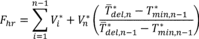 where n
and V*i are the same quantities as defined above, and V*n = the
volume of water drawn during the nth (final) draw of the
first-hour rating test, gal (L). T *del,n−1 = the average
water outlet temperature measured during the (n−1)th draw of
the first-hour rating test, °F ( °C). T *del,n = the average
water outlet temperature measured during the nth (final)
draw of the first-hour rating test, °F ( °C). T*min,n−1 = the
minimum water outlet temperature measured during the (n−1)th
draw of the first-hour rating test, °F ( °C).
where n
and V*i are the same quantities as defined above, and V*n = the
volume of water drawn during the nth (final) draw of the
first-hour rating test, gal (L). T *del,n−1 = the average
water outlet temperature measured during the (n−1)th draw of
the first-hour rating test, °F ( °C). T *del,n = the average
water outlet temperature measured during the nth (final)
draw of the first-hour rating test, °F ( °C). T*min,n−1 = the
minimum water outlet temperature measured during the (n−1)th
draw of the first-hour rating test, °F ( °C).
6.2 Maximum GPM (L/min) Rating Computation. Compute the maximum GPM (L/min) rating, Fmax, as:
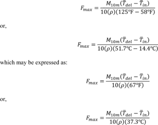 Where:
M10m = the mass of water collected during the 10-minute test, lb
(kg). T del = the average delivery temperature, °F ( °C).
T in = the average inlet temperature, °F ( °C). ρ = the
density of water at the average delivery temperature, lb/gal
(kg/L).
Where:
M10m = the mass of water collected during the 10-minute test, lb
(kg). T del = the average delivery temperature, °F ( °C).
T in = the average inlet temperature, °F ( °C). ρ = the
density of water at the average delivery temperature, lb/gal
(kg/L).
If a water meter is used, the maximum GPM (L/min) rating is computed as:
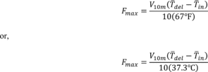 Where:
V10m = the volume of water measured during the 10-minute test, gal
(L). T del = as defined in this section. T in = as
defined in this section.
Where:
V10m = the volume of water measured during the 10-minute test, gal
(L). T del = as defined in this section. T in = as
defined in this section.
6.3 Computations for Water Heaters with a Rated Storage Volume Greater Than or Equal to 2 Gallons.
6.3.1 Storage Tank Capacity. The storage tank capacity, Vst, is computed as follows:
 Where:
Vst = the storage capacity of the water heater, gal (L) Wf = the
weight of the storage tank when completely filled with water, lb
(kg) Wt = the (tare) weight of the storage tank when completely
empty, lb (kg) ρ = the density of water used to fill the tank
measured at the temperature of the water, lb/gal (kg/L)
Where:
Vst = the storage capacity of the water heater, gal (L) Wf = the
weight of the storage tank when completely filled with water, lb
(kg) Wt = the (tare) weight of the storage tank when completely
empty, lb (kg) ρ = the density of water used to fill the tank
measured at the temperature of the water, lb/gal (kg/L)
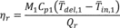
6.3.2 Recovery Efficiency. The recovery efficiency for gas, oil, and heat pump storage-type water heaters, ηr, is computed as:
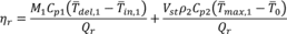 Where: M1
= total mass removed from the start of the 24-hour simulated-use
test to the end of the first recovery period, lb (kg), or, if the
volume of water is being measured, M1 = V1ρ1 Where: V1 = total
volume removed from the start of the 24-hour simulated-use test to
the end of the first recovery period, gal (L). ρ1 = density of the
water at the water temperature measured at the point where the flow
volume is measured, lb/gal (kg/L). Cp1 = specific heat of the
withdrawn water evaluated at (T del,1 + T in,1)/2,
Btu/(lb· °F) (kJ/(kg· °C)) T del,1 = average water outlet
temperature measured during the draws from the start of the 24-hour
simulated-use test to the end of the first recovery period, °F (
°C). T in,1 = average water inlet temperature measured
during the draws from the start of the 24-hour simulated-use test
to the end of the first recovery period, °F ( °C). Vst = as defined
in section 6.3.1. ρ2 = density of stored hot water evaluated at
(T max,1 + T o)/2, lb/gal (kg/L). Cp2 = specific heat
of stored hot water evaluated at (T max,1 + T o)/2,
Btu/(lb· °F) (kJ/(kg· °C). T max,1 = maximum mean tank
temperature recorded after cut-out following the first recovery of
the 24-hour simulated use test, °F ( °C). T o = maximum mean
tank temperature recorded prior to the first draw of the 24-hour
simulated-use test, °F ( °C). Qr = the total energy used by the
water heater between cut-out prior to the first draw and cut-out
following the first recovery period, including auxiliary energy
such as pilot lights, pumps, fans, etc., Btu (kJ). (Electrical
auxiliary energy shall be converted to thermal energy using the
following conversion: 1 kWh = 3412 Btu).
Where: M1
= total mass removed from the start of the 24-hour simulated-use
test to the end of the first recovery period, lb (kg), or, if the
volume of water is being measured, M1 = V1ρ1 Where: V1 = total
volume removed from the start of the 24-hour simulated-use test to
the end of the first recovery period, gal (L). ρ1 = density of the
water at the water temperature measured at the point where the flow
volume is measured, lb/gal (kg/L). Cp1 = specific heat of the
withdrawn water evaluated at (T del,1 + T in,1)/2,
Btu/(lb· °F) (kJ/(kg· °C)) T del,1 = average water outlet
temperature measured during the draws from the start of the 24-hour
simulated-use test to the end of the first recovery period, °F (
°C). T in,1 = average water inlet temperature measured
during the draws from the start of the 24-hour simulated-use test
to the end of the first recovery period, °F ( °C). Vst = as defined
in section 6.3.1. ρ2 = density of stored hot water evaluated at
(T max,1 + T o)/2, lb/gal (kg/L). Cp2 = specific heat
of stored hot water evaluated at (T max,1 + T o)/2,
Btu/(lb· °F) (kJ/(kg· °C). T max,1 = maximum mean tank
temperature recorded after cut-out following the first recovery of
the 24-hour simulated use test, °F ( °C). T o = maximum mean
tank temperature recorded prior to the first draw of the 24-hour
simulated-use test, °F ( °C). Qr = the total energy used by the
water heater between cut-out prior to the first draw and cut-out
following the first recovery period, including auxiliary energy
such as pilot lights, pumps, fans, etc., Btu (kJ). (Electrical
auxiliary energy shall be converted to thermal energy using the
following conversion: 1 kWh = 3412 Btu).
The recovery efficiency for electric water heaters with immersed heating elements is assumed to be 98 percent.
6.3.3 Hourly Standby Losses. The energy consumed as part of the standby loss test of the 24-hour simulated-use test, Qstby, is computed as:
Qstby = Qsu,f - Qsu,o Where:Qsu,0 = cumulative energy consumption of the water heater from the start of the 24-hour simulated-use test to the time at which the maximum mean tank temperature is attained starting five minutes after the recovery following the end of the first draw cluster, Btu (kJ).
Qsu,f = cumulative energy consumption of the water heater from the start of the 24-hour simulated-use test to the minute prior to the start of the draw following the end of the first draw cluster or the minute prior to a recovery occurring at the start of the draw following the end of the first draw cluster, Btu (kJ).
The hourly standby energy losses are computed as:
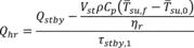 Where:
Qhr = the hourly standby energy losses of the water heater, Btu/h
(kJ/h). Vst = as defined in section 6.3.1 of this appendix. ρ =
density of stored hot water, (T su,f + T su,0)/2,
lb/gal (kg/L). Cp = specific heat of the stored water, (T
su,f + T su,0)/2, Btu/(lb·F), (kJ/(kg·K)) T su,f =
the mean tank temperature observed at the minute prior to the start
of the draw following the first draw cluster or the minute prior to
a recovery occurring at the start of the draw following the end of
the first draw cluster, °F ( °C). T su,0 = the maximum mean
tank temperature observed starting five minutes after the first
recovery following the final draw of the first draw cluster, °F (
°C). ηr = as defined in section 6.3.2 of this appendix. τstby,1 =
elapsed time between the time at which the maximum mean tank
temperature is observed starting five minutes after recovery from
the first draw cluster and the minute prior to the start of the
first draw following the end of the first draw cluster of the
24-hour simulated-use test or the minute prior to a recovery
occurring at the start of the draw following the end of the first
draw cluster, h.
Where:
Qhr = the hourly standby energy losses of the water heater, Btu/h
(kJ/h). Vst = as defined in section 6.3.1 of this appendix. ρ =
density of stored hot water, (T su,f + T su,0)/2,
lb/gal (kg/L). Cp = specific heat of the stored water, (T
su,f + T su,0)/2, Btu/(lb·F), (kJ/(kg·K)) T su,f =
the mean tank temperature observed at the minute prior to the start
of the draw following the first draw cluster or the minute prior to
a recovery occurring at the start of the draw following the end of
the first draw cluster, °F ( °C). T su,0 = the maximum mean
tank temperature observed starting five minutes after the first
recovery following the final draw of the first draw cluster, °F (
°C). ηr = as defined in section 6.3.2 of this appendix. τstby,1 =
elapsed time between the time at which the maximum mean tank
temperature is observed starting five minutes after recovery from
the first draw cluster and the minute prior to the start of the
first draw following the end of the first draw cluster of the
24-hour simulated-use test or the minute prior to a recovery
occurring at the start of the draw following the end of the first
draw cluster, h.
The standby heat loss coefficient for the tank is computed as:
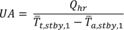 Where: UA
= standby heat loss coefficient of the storage tank, Btu/(h· °F),
(kJ/(h· °C). T t,stby,1 = overall average storage tank
temperature between the time when the maximum mean tank temperature
is observed starting five minutes after cut-out following the first
draw cluster and the minute prior to commencement of the next draw
following the first draw cluster of the 24-hour simulated-use test
or the minute prior to a recovery occurring at the start of the
draw following the end of the first draw cluster, °F ( °C).
T a,stby,1 = overall average ambient temperature between the
time when the maximum mean tank temperature is observed starting
five minutes after cut-out following the first draw cluster and the
minute prior to commencement of the next draw following the first
draw cluster of the 24-hour simulated-use test or the minute prior
to a recovery occurring at the start of the draw following the end
of the first draw cluster, °F ( °C).
Where: UA
= standby heat loss coefficient of the storage tank, Btu/(h· °F),
(kJ/(h· °C). T t,stby,1 = overall average storage tank
temperature between the time when the maximum mean tank temperature
is observed starting five minutes after cut-out following the first
draw cluster and the minute prior to commencement of the next draw
following the first draw cluster of the 24-hour simulated-use test
or the minute prior to a recovery occurring at the start of the
draw following the end of the first draw cluster, °F ( °C).
T a,stby,1 = overall average ambient temperature between the
time when the maximum mean tank temperature is observed starting
five minutes after cut-out following the first draw cluster and the
minute prior to commencement of the next draw following the first
draw cluster of the 24-hour simulated-use test or the minute prior
to a recovery occurring at the start of the draw following the end
of the first draw cluster, °F ( °C).
6.3.4 Daily Water Heating Energy Consumption. The daily water heating energy consumption, Qd, is computed as:
 Where: Q
= Qf + Qe = total energy used by the water heater during the
24-hour simulated-use test, including auxiliary energy such as
pilot lights, pumps, fans, etc., Btu (kJ). (Electrical energy shall
be converted to thermal energy using the following conversion: 1kWh
= 3412 Btu.) Qf = total fossil fuel energy used by the water heater
during the 24-hour simulated-use test, Btu (kJ). Qe = total
electrical energy used during the 24-hour simulated-use test, Btu
(kJ). Vst = as defined in section 6.3.1 of this appendix. ρ =
density of the stored hot water, evaluated at (T 24 +
T 0)/2, lb/gal (kg/L) Cp = specific heat of the stored
water, evaluated at (T 24 + T 0)/2, Btu/(lb·F),
(kJ/(kg·K)). T 24 = mean tank temperature at the end of the
24-hour simulated-use test, °F ( °C). T 0 = mean tank
temperature at the beginning of the 24-hour simulated-use test,
recorded one minute before the first draw is initiated, °F ( °C).
ηr = as defined in section 6.3.2 of this appendix.
Where: Q
= Qf + Qe = total energy used by the water heater during the
24-hour simulated-use test, including auxiliary energy such as
pilot lights, pumps, fans, etc., Btu (kJ). (Electrical energy shall
be converted to thermal energy using the following conversion: 1kWh
= 3412 Btu.) Qf = total fossil fuel energy used by the water heater
during the 24-hour simulated-use test, Btu (kJ). Qe = total
electrical energy used during the 24-hour simulated-use test, Btu
(kJ). Vst = as defined in section 6.3.1 of this appendix. ρ =
density of the stored hot water, evaluated at (T 24 +
T 0)/2, lb/gal (kg/L) Cp = specific heat of the stored
water, evaluated at (T 24 + T 0)/2, Btu/(lb·F),
(kJ/(kg·K)). T 24 = mean tank temperature at the end of the
24-hour simulated-use test, °F ( °C). T 0 = mean tank
temperature at the beginning of the 24-hour simulated-use test,
recorded one minute before the first draw is initiated, °F ( °C).
ηr = as defined in section 6.3.2 of this appendix.
6.3.5 Adjusted Daily Water Heating Energy Consumption. The adjusted daily water heating energy consumption, Qda, takes into account that the ambient temperature may differ from the nominal value of 67.5 °F (19.7 °C) due to the allowable variation in surrounding ambient temperature of 65 °F (18.3 °C) to 70 °C (21.1 °C). The adjusted daily water heating energy consumption is computed as:
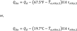 Where:
Qda = the adjusted daily water heating energy consumption, Btu
(kJ). Qd = as defined in section 6.3.4 of this appendix. T
a,stby,2 = the average ambient temperature during the total standby
portion, τstby,2, of the 24-hour simulated-use test, °F ( °C). UA =
as defined in section 6.3.3 of this appendix. τstby,2 = the number
of hours during the 24-hour simulated-use test when water is not
being withdrawn from the water heater.
Where:
Qda = the adjusted daily water heating energy consumption, Btu
(kJ). Qd = as defined in section 6.3.4 of this appendix. T
a,stby,2 = the average ambient temperature during the total standby
portion, τstby,2, of the 24-hour simulated-use test, °F ( °C). UA =
as defined in section 6.3.3 of this appendix. τstby,2 = the number
of hours during the 24-hour simulated-use test when water is not
being withdrawn from the water heater.
A modification is also needed to take into account that the temperature difference between the outlet water temperature and supply water temperature may not be equivalent to the nominal value of 67 °F (125 °F-58 °F) or 37.3 °C (51.7 °C-14.4 °C). The following equations adjust the experimental data to a nominal 67 °F(37.3 °C) temperature rise.
The energy used to heat water, Btu/day (kJ/day), may be computed as:
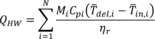 Where: N
= total number of draws in the draw pattern. Mi = the mass
withdrawn for the ith draw (i = 1 to N), lb (kg) Cpi = the
specific heat of the water of the ith draw evaluated at
(T del,i + T in,i)/2, Btu/(lb· °F) (kJ/(kg· °C)).
T del,i = the average water outlet temperature measured
during the ith draw (i = 1 to N), °F ( °C). T in,i =
the average water inlet temperature measured during the ith
draw (i = 1 to N), °F ( °C). ηr = as defined in section 6.3.2 of
this appendix.
Where: N
= total number of draws in the draw pattern. Mi = the mass
withdrawn for the ith draw (i = 1 to N), lb (kg) Cpi = the
specific heat of the water of the ith draw evaluated at
(T del,i + T in,i)/2, Btu/(lb· °F) (kJ/(kg· °C)).
T del,i = the average water outlet temperature measured
during the ith draw (i = 1 to N), °F ( °C). T in,i =
the average water inlet temperature measured during the ith
draw (i = 1 to N), °F ( °C). ηr = as defined in section 6.3.2 of
this appendix.
The energy required to heat the same quantity of water over a 67 °F (37.3 °C) temperature rise, Btu/day (kJ/day), is:
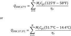
The difference between these two values is:
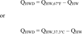
QHWD = QHW,67 °F − QHW or QHWD = QHW,37.3 °C − QHW This difference (QHWD) must be added to the adjusted daily water heating energy consumption value. Thus, the daily energy consumption value which takes into account that the ambient temperature may not be 67.5 °F (19.7 °C) and that the temperature rise across the storage tank may not be 67 °F (37.3 °C) is: Qdm = Qda + QHWD6.3.6 Uniform Energy Factor. The uniform energy factor, UEF, is computed as:
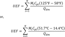
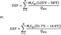 Where: N
= total number of draws in the draw pattern Qdm = the modified
daily water heating energy consumption as computed in accordance
with section 6.3.5 of this appendix, Btu (kJ) Mi = the mass
withdrawn for the ith draw (i = 1 to N), lb (kg) Cpi = the
specific heat of the water of the ith draw, evaluated at
(125 °F + 58 °F)/2 = 91.5 °F ((51.7 °C + 14.4 °C)/2 = 33 °C),
Btu/(lb· °F) (kJ/(kg· °C)).
Where: N
= total number of draws in the draw pattern Qdm = the modified
daily water heating energy consumption as computed in accordance
with section 6.3.5 of this appendix, Btu (kJ) Mi = the mass
withdrawn for the ith draw (i = 1 to N), lb (kg) Cpi = the
specific heat of the water of the ith draw, evaluated at
(125 °F + 58 °F)/2 = 91.5 °F ((51.7 °C + 14.4 °C)/2 = 33 °C),
Btu/(lb· °F) (kJ/(kg· °C)).
6.3.7 Annual Energy Consumption. The annual energy consumption for water heaters with rated storage volumes greater than or equal to 2 gallons is computed as:
 Where:
UEF = the uniform energy factor as computed in accordance with
section 6.3.6 of this appendix 365 = the number of days in a year V
= the volume of hot water drawn during the applicable draw pattern,
gallons = 10 for the very-small-usage draw pattern = 38 for the
low-usage draw pattern = 55 for the medium-usage draw pattern = 84
for high-usage draw pattern ρ = 8.24 lbm/gallon, the density of
water at 125 °F CP = 1.00 Btu/lbm °F, the specific heat of water at
91.5 °F 67 = the nominal temperature difference between inlet and
outlet water
Where:
UEF = the uniform energy factor as computed in accordance with
section 6.3.6 of this appendix 365 = the number of days in a year V
= the volume of hot water drawn during the applicable draw pattern,
gallons = 10 for the very-small-usage draw pattern = 38 for the
low-usage draw pattern = 55 for the medium-usage draw pattern = 84
for high-usage draw pattern ρ = 8.24 lbm/gallon, the density of
water at 125 °F CP = 1.00 Btu/lbm °F, the specific heat of water at
91.5 °F 67 = the nominal temperature difference between inlet and
outlet water
6.3.8 Annual Electrical Energy Consumption. The annual electrical energy consumption in kilowatt-hours for water heaters with rated storage volumes greater than or equal to 2 gallons, Eannual,e, is computed as:
Eannual,e = Eannual*(Qe/Q)/3412 Where: Eannual = the annual energy consumption as determined in accordance with section 6.3.7, Btu (kJ) Qe = the daily electrical energy consumption as defined in section 6.3.4 of this appendix, Btu (kJ). Q = total energy used by the water heater during the 24-hour simulated-use test in accordance with section 6.3.4 of this appendix, Btu (kJ) 3412 = conversion factor from Btu to kWh6.3.9 Annual Fossil Fuel Energy Consumption. The annual fossil fuel energy consumption for water heaters with rated storage volumes greater than or equal to 2 gallons, Eannual,f, is computed as:
Eannual,f = Eannual − (Eannual,e × 3412) Where: Eannual = the annual energy consumption as determined in accordance with section 6.3.7 of this appendix, Btu (kJ) Eannual,e = the annual electrical energy consumption as determined in accordance with section 6.3.8 of this appendix, kWh 3412 = conversion factor from kWh to Btu6.4 Computations for Water Heaters With Rated Storage Volume Less Than 2 Gallons.
6.4.1 Recovery Efficiency. The recovery efficiency, ηr, is computed as:
 Where: M1
= total mass removed during the first draw of the 24-hour
simulated-use test, lb (kg), or, if the volume of water is being
measured, M1 = V1 · ρ Where: V1 = total volume removed during the
first draw of the 24-hour simulated-use test, gal (L). ρ = density
of the water at the water temperature measured at the point where
the flow volume is measured, lb/gal(kg/L). Cp1 = specific heat of
the withdrawn water, (T del,1 ∓ T in,1)/2, Btu/(lb ·
°F) (kJ/(kg · °C)). T del,1 = average water outlet
temperature measured during the first draw of the 24-hour
simulated-use test, °F ( °C). T in,1 = average water inlet
temperature measured during the first draw of the 24-hour
simulated-use test, °F ( °C). Qr = the total energy used by the
water heater between cut-out prior to the first draw and cut-out
following the first draw, including auxiliary energy such as pilot
lights, pumps, fans, etc., Btu (kJ). (Electrical auxiliary energy
shall be converted to thermal energy using the following
conversion: 1 kWh = 3412 Btu.)
Where: M1
= total mass removed during the first draw of the 24-hour
simulated-use test, lb (kg), or, if the volume of water is being
measured, M1 = V1 · ρ Where: V1 = total volume removed during the
first draw of the 24-hour simulated-use test, gal (L). ρ = density
of the water at the water temperature measured at the point where
the flow volume is measured, lb/gal(kg/L). Cp1 = specific heat of
the withdrawn water, (T del,1 ∓ T in,1)/2, Btu/(lb ·
°F) (kJ/(kg · °C)). T del,1 = average water outlet
temperature measured during the first draw of the 24-hour
simulated-use test, °F ( °C). T in,1 = average water inlet
temperature measured during the first draw of the 24-hour
simulated-use test, °F ( °C). Qr = the total energy used by the
water heater between cut-out prior to the first draw and cut-out
following the first draw, including auxiliary energy such as pilot
lights, pumps, fans, etc., Btu (kJ). (Electrical auxiliary energy
shall be converted to thermal energy using the following
conversion: 1 kWh = 3412 Btu.)
6.4.2 Daily Water Heating Energy Consumption. The daily water heating energy consumption, Qd, is computed as:
Qd = Q Where: Q = Qf + Qe = the energy used by the water heater during the 24-hour simulated-use test. Qf = total fossil fuel energy used by the water heater during the 24-hour simulated-use test, Btu (kJ). Qe = total electrical energy used during the 24-hour simulated-use test, Btu (kJ).A modification is needed to take into account that the temperature difference between the outlet water temperature and supply water temperature may not be equivalent to the nominal value of 67 °F (125 °F-58 °F) or 37.3 °C (51.7 °C-14.4 °C). The following equations adjust the experimental data to a nominal 67 °F (37.3 °C) temperature rise.
The energy used to heat water may be computed as:
 Where: N
= total number of draws in the draw pattern Mi = the mass withdrawn
for the ith draw(i = 1 to N), lb (kg) Cpi = the
specific heat of the water of the ith draw evaluated at
(T del,i + T in,i)/2, Btu/(lb · °F) (kJ/(kg · °C)).
T del,i = the average water outlet temperature measured
during the ith draw (i = 1 to N), °F ( °C). T
in,i = the average water inlet temperature measured during the
ith draw (i = 1 to N), °F ( °C). ηr = as defined in
section 6.4.1 of this appendix.
Where: N
= total number of draws in the draw pattern Mi = the mass withdrawn
for the ith draw(i = 1 to N), lb (kg) Cpi = the
specific heat of the water of the ith draw evaluated at
(T del,i + T in,i)/2, Btu/(lb · °F) (kJ/(kg · °C)).
T del,i = the average water outlet temperature measured
during the ith draw (i = 1 to N), °F ( °C). T
in,i = the average water inlet temperature measured during the
ith draw (i = 1 to N), °F ( °C). ηr = as defined in
section 6.4.1 of this appendix.
The energy required to heat the same quantity of water over a 67 °F (37.3 °C) temperature rise is:
 Where: N
= total number of draws in the draw pattern Mi = the mass withdrawn
during the ith draw, lb (kg) Cpi = the specific heat of
water of the ith draw, Btu/(lb · °F) (kJ/(kg · °C)) ηr = as
defined in section 6.4.1 of this appendix.
Where: N
= total number of draws in the draw pattern Mi = the mass withdrawn
during the ith draw, lb (kg) Cpi = the specific heat of
water of the ith draw, Btu/(lb · °F) (kJ/(kg · °C)) ηr = as
defined in section 6.4.1 of this appendix.
The difference between these two values is:
 This
difference (QHWD) must be added to the daily water heating energy
consumption value. Thus, the daily energy consumption value, which
takes into account that the temperature rise across the water
heater may not be 67 °F (37.3 °C), is: Qdm = Qd + QHWD
This
difference (QHWD) must be added to the daily water heating energy
consumption value. Thus, the daily energy consumption value, which
takes into account that the temperature rise across the water
heater may not be 67 °F (37.3 °C), is: Qdm = Qd + QHWD
6.4.3 Uniform Energy Factor. The uniform energy factor, UEF, is computed as:
 Where: N
= total number of draws in the draw pattern Qdm = the modified
daily water heating energy consumption as computed in accordance
with section 6.4.2 of this appendix, Btu (kJ) Mi = the mass
withdrawn for the ith draw(i = 1 to N), lb (kg) Cpi = the
specific heat of the water at the ith draw, evaluated at
(125 °F + 58 °F)/2 = 91.5 °F ((51.7 °C + 14.4 °C)/2 = 33.1 °C),
Btu/(lb · °F) (kJ/(kg · °C)).
Where: N
= total number of draws in the draw pattern Qdm = the modified
daily water heating energy consumption as computed in accordance
with section 6.4.2 of this appendix, Btu (kJ) Mi = the mass
withdrawn for the ith draw(i = 1 to N), lb (kg) Cpi = the
specific heat of the water at the ith draw, evaluated at
(125 °F + 58 °F)/2 = 91.5 °F ((51.7 °C + 14.4 °C)/2 = 33.1 °C),
Btu/(lb · °F) (kJ/(kg · °C)).
6.4.4 Annual Energy Consumption. The annual energy consumption for water heaters with rated storage volumes less than 2 gallons, Eannual, is computed as:
 Where:
UEF = the uniform energy factor as computed in accordance with
section 6.4.3 of this appendix 365 = the number of days in a year.
V = the volume of hot water drawn during the applicable draw
pattern, gallons = 10 for the very-small-usage draw pattern = 38
for the low-usage draw pattern = 55 for the medium-usage draw
pattern = 84 for high-usage draw pattern ρ = 8.24 lbm/gallon, the
density of water at 125 °F CP = 1.00 Btu/lbm °F, the specific heat
of water at 91.5 °F 67 = the nominal temperature difference between
inlet and outlet water
Where:
UEF = the uniform energy factor as computed in accordance with
section 6.4.3 of this appendix 365 = the number of days in a year.
V = the volume of hot water drawn during the applicable draw
pattern, gallons = 10 for the very-small-usage draw pattern = 38
for the low-usage draw pattern = 55 for the medium-usage draw
pattern = 84 for high-usage draw pattern ρ = 8.24 lbm/gallon, the
density of water at 125 °F CP = 1.00 Btu/lbm °F, the specific heat
of water at 91.5 °F 67 = the nominal temperature difference between
inlet and outlet water
6.4.5 Annual Electrical Energy Consumption. The annual electrical energy consumption in kilowatt-hours for water heaters with rated storage volumes less than 2 gallons, Eannual, e, is computed as:
Eannual,e = Eannual*(Qe/Q)/3412 Where: Qe = the daily electrical energy consumption as defined in section 6.4.2 of this appendix, Btu (kJ) Eannual = the annual energy consumption as determined in accordance with section 6.4.4 of this appendix, Btu (kJ) Q = total energy used by the water heater during the 24-hour simulated-use test in accordance with section 6.4.2 of this appendix, Btu (kJ) Qdm = the modified daily water heating energy consumption as computed in accordance with section 6.4.2 of this appendix, Btu (kJ) 3412 = conversion factor from Btu to kWh6.4.6 Annual Fossil Fuel Energy Consumption. The annual fossil fuel energy consumption for water heaters with rated storage volumes less than 2 gallons, Eannual,f, is computed as:
Eannual,f = Eannual−(Eannual,e × 3412) Where: Eannual,e = the annual electrical energy consumption as defined in section 6.4.5 of this appendix, kWh. Eannual = the annual energy consumption as defined in section 6.4.4 of this appendix, Btu (kJ) 3412 = conversion factor from kWh to Btu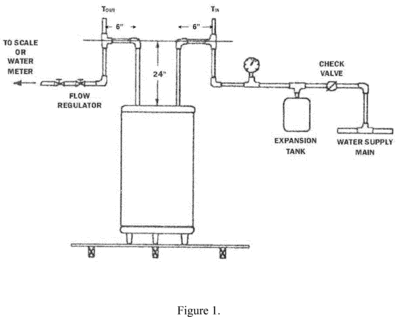
 [79 FR 40567, July
11, 2014]
[79 FR 40567, July
11, 2014]