Title 46
SECTION 56.70-15
56.70-15 Procedure.
§ 56.70-15 Procedure.(a) General. (1) Qualification of the welding procedures to be used, and of the performance of welders and operators, is required, and shall comply with the requirements of part 57 of this subchapter.
(2) No welding shall be done if there is direct impingement of rain, snow, sleet, or high wind on the piping component weldment.
(3) Sections of pipe shall be welded insofar as possible in the fabricating shop. Prior to welding Class I piping or low temperature piping, the fabricator shall request a marine inspector to visit his plant to examine his fabricating equipment and to witness the qualification tests required by part 57 of this subchapter. One test specimen shall be prepared for each process and welding position to be employed in the fabrication.
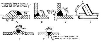
(b) Girth butt welds. (1) Girth butt welds must be complete penetration welds and may be made with a single vee, double vee, or other suitable type of groove, with or without backing rings or consumable inserts.
(2) Girth butt welds in Class I, I-L, and II-L piping systems shall be double welded butt joints or equivalent single welded butt joints for pipe diameters exceeding three-fourth inch nominal pipe size. The use of a single welded butt joint employing a backing ring (note restrictions in paragraph (b)(3)(iv) of this section) on the inside of the pipe is an acceptable equivalent for Class I and Class II-L applications, but not permitted for Class I-L applications. Single welded butt joints employing either an inert gas for first pass backup or a consumable insert ring may be considered the equivalent of a double welded butt joint for all classes of piping and is preferable for Class I-L and II-L systems where double butt welds cannot be used. Appropriate welding procedure qualification tests shall be conducted as specified in part 57 of this subchapter. A first pass inert gas backup is intended to mean that the inside of the pipe is purged with inert gas and that the root is welded with the inert gas metal arc (mig) or inert gas tungsten arc (tig) processes. Classes I, I-L, and II-L piping are required to have the inside of the pipe machined for good fit up if the misalignment exceeds that specified in § 56.70-10(a)(3). In the case of Class II piping the machining of the inside of the pipe may be omitted. For single welded joints, where possible, the inside of the joint shall be examined visually to assure full penetration. Radiographic examination of at least 20 percent of single welded joints to check for penetration is required for all Class I and Class I-L systems regardless of size following the requirements of § 56.95-10. Ultrasonic testing may be utilized in lieu of radiographic examination if the procedures are approved.
(3) For Class II piping, the type of joints shall be similar to Class I piping, with the following exceptions:
(i) Single-welded butt joints may be employed without the use of backing rings in all sizes provided that the weld is chipped or ground flush on the root side of the weld.
(ii) For services such as vents, overflows, and gravity drains, the backing ring may be eliminated and the root of the weld need not be ground.
(iii) Square-groove welds without edge preparation may be employed for butt joints in vents, overflows, and gravity drains where the pipe wall thickness does not exceed three-sixteenth inch.
(iv) The crimped or forged backing ring with continuous projection around the outside of the ring is acceptable only for Class II piping. The projection must be completely fused.
(4) Tack welds which become part of the finished weld, shall be made by a qualified welder. Tack welds made by an unqualified welder shall be removed. Tack welds which are not removed shall be made with an electrode which is the same as or equivalent to the electrode to be used for the first pass. Their stopping and starting ends must be properly prepared by grinding or other suitable means so that they may be satisfactorily incorporated into the final weld. Tack welds which have cracked shall be removed.
(5) When components of different outside diameters are welded together, the weld joint must be filled to the outside surface of the component having the larger diameter. There must be a gradual transition, not exceeding a slope of 1:3, in the weld between the two surfaces. To avoid unnecessary weld deposit, the outside surface of the component having the larger diameter must be tapered at an angle not to exceed 30 degrees with the axis of the pipe. (See Fig. 127.4.2 of ASME B31.1 (incorporated by reference; see 46 CFR 56.01-2).)
(6) As-welded surfaces are permitted; however, the surface of the welds must be sufficiently free from coarse ripple, grooves, overlaps, abrupt ridges and valleys to meet the following:
(i) The surface condition of the finished welds must be suitable for the proper interpretation of radiographic and other nondestructive examinations when nondestructive examinations are required by § 56.95-10. In those cases where there is a question regarding the surface condition on the interpretation of a radiographic film, the film must be compared to the actual weld surface for interpretation and determination of acceptability.
(ii) Reinforcements are permitted in accordance with Table 56.70-15.
(iii) Undercuts must not exceed 1/32-inch and must not encroach on the minimum required section thickness.
(iv) If the surface of the weld requires grinding to meet the above criteria, care must be taken to avoid reducing the weld or base material below the minimum required thickness.
(7) The type and extent of examination required for girth butt welds is specified in § 56.95-10.
(8) Sections of welds that are shown by radiography or other examination to have any of the following type of imperfections shall be judged unacceptable and shall be repaired as provided in paragraph (f) of this section:
(i) Any type of crack or zone of incomplete fusion or penetration.
(ii) Any slag inclusion or porosity greater in extent than those specified as acceptable set forth in PW-51 of section I of the ASME Boiler and Pressure Vessel Code (incorporated by reference; see 46 CFR 56.01-2).
(iii) Undercuts in the external surfaces of butt welds which are more than 1/32-inch deep.
(iv) Concavity on the root side of full penetration girth butt welds where the resulting weld thickness is less than the minimum pipe wall thickness required by this subchapter. Weld reinforcement up to a maximum of 1/32-inch thickness may be considered as pipe wall thickness in such cases.
(c) Longitudinal butt welds. Longitudinal butt welds in piping components not made in accordance with the standards and specifications listed in 56.60-1 (a) and (b) must meet the requirements of paragraph 104.7 of ASME B31.1 (incorporated by reference; see 46 CFR 56.01-2) and may be examined nondestructively by an acceptable method. Imperfections shall not exceed the limits established for girth butt welds except that no undercutting shall be permitted in longitudinal butt welds. See also § 56.60-2(b).
(d) Fillet welds. (1) Fillet welds may vary from convex to concave. The size of a fillet weld is determined as shown in Figure 127.4.4A in ASME B31.1. Fillet weld details for socket-welding components must meet § 56.30-5(c) of this part. Fillet weld details for flanges must meet § 56.30-10(c) of this part. Fillet weld details for flanges must meet § 56.30-10 of this part.
(2) The limitations on cracks and undercutting set forth in paragraph (b)(8) of this section for girth welds are also applicable to fillet welds.
(3) Class I piping not exceeding 3 inches nominal pipe size and not subject to full radiography by § 56.95-10 of this part may be joined by sleeves fitted over pipe ends or by socket type joints. Where full radiography is required, only butt type joints may be used. The inside diameter of the sleeve must not exceed the outside diameter of the pipe or tube by more than 0.080 inch. Fit between socket and pipe must conform to applicable standards for socket weld fittings. Depth of insertion of pipe or tube within the socket or sleeve must not be less than three-eighths inch. The fillet weld must be deposited in a minimum of two passes, unless specifically approved otherwise in a special procedure qualification. Requirements for joints employing socket weld and slip-on flanges are in § 56.30-10 of this part.
(4) Sleeve and socket type joints may be used in Class II piping systems without restriction as to size of pipe or tubing joined. Applicable standards must be followed on fit. The fillet welds must be deposited in a minimum of two passes, unless specifically approved otherwise in a special procedure qualification. Requirements for joints employing socket weld and slip-on flanges are in § 56.30-10 of this part.
(e) Seal welds (reproduces 127.4.5). (1) Where seal welding of threaded joints is performed, threads shall be entirely covered by the seal weld. Seal welding shall be done by qualified welders.
(2) The limitation on cracks and undercutting set forth in § 56.70-15(b)(8) for girth welds are also applicable to seal welds.
(f) Weld defect repairs. (1) All defects in welds requiring repair must be removed by a flame or arc-gouging, grinding, chipping, or machining. Repair welds must be made in accordance with the same procedures used for original welds, or by another welding process if it is a part of a qualified procedure, recognizing that the cavity to be repaired may differ in contour and dimensions from the original joint. The types, extent, and method of examination and limits of imperfections of repair welds shall be the same as for the original weld.
(2) Preheating may be required for flame-gouging or arc-gouging certain alloy materials of the air hardening type in order to prevent surface checking or cracking adjacent to the flame or arc-gouged surface.
(g) Welded branch connections. (1) Figure 127.4.8A, Figure 127.4.8B, and Figure 127.4.8C of ASME B31.1 show typical details of branch connections with and without added reinforcement. However, no attempt has been made to show all acceptable types of construction and the fact that a certain type of construction is illustrated does not indicate that it is recommended over other types not illustrated. See also Figure 56.70-15(g) for additional pipe connections.
(2) Figure 127.4.8D of ASME B31.1 shows basic types of weld attachments used in the fabrication of branch connections. The location and minimum size of these attachment welds shall conform to the requirements of this paragraph. Weld sizes shall be calculated in accordance with 104.3.1 of ASME B31.1, but shall not be less than the sizes shown in Figure 127.4.8D and F of ASME B31.1.
(3) The notations and symbols used in this paragraph and in Figure 127.4.8D and F of ASME B31.1 are as follows:
 Figure
56.70-15(g) - Acceptable types of welded pipe connections tn =
nominal thickness of branch wall less corrosion allowance, inches.
tc = the smaller of 1/4 inch or 0.7tn. te = nominal thickness of
reinforcing element (ring or saddle), inches (te = 0 if there is no
added reinforcement). tmin = the smaller of tn or te. tw =
dimension of partial penetration weld, inches.
Figure
56.70-15(g) - Acceptable types of welded pipe connections tn =
nominal thickness of branch wall less corrosion allowance, inches.
tc = the smaller of 1/4 inch or 0.7tn. te = nominal thickness of
reinforcing element (ring or saddle), inches (te = 0 if there is no
added reinforcement). tmin = the smaller of tn or te. tw =
dimension of partial penetration weld, inches.
(4) Branch connections (including specially made, integrally reinforced branch connection fittings) that abut the outside surface of the run wall, or that are inserted through an opening cut in the run wall, shall have opening and branch contour to provide a good fit and shall be attached by means of full penetration groove welds except as otherwise permitted in paragraph (g)(7) of this section. The full penetration groove welds shall be finished with cover fillet welds having a minimum throat dimension not less than 2tc. The limitation as to imperfection of these groove welds shall be as set forth in 127.4.2(C) of ASME B31.1 for girth welds.
(5) In branch connections having reinforcement pads or saddles, the reinforcement shall be attached by welds at the outer edge and at the branch periphery as follows:
(i) If the weld joining the added reinforcement to the branch is a full penetration groove weld, it shall be finished with a cover fillet weld having a minimum throat dimension not less than tc the weld at the outer edge, joining the added reinforcement to the run, shall be a fillet weld with a minimum throat dimension of 0.5 te.
(ii) If the weld joining the added reinforcement to the branch is a fillet weld, the throat dimension shall not be less than 0.7 tmin. The weld at the outer edge joining the outer reinforcement to the run shall also be a fillet weld with a minimum throat dimension of 0.5 te.
(6) When rings or saddles are used, a vent hole shall be provided (at the side and not at the crotch) in the ring or saddle to reveal leakage in the weld between branch and main run and to provide venting during welding and heat treating operations. Rings or saddles may be made in more than one piece if the joints between the pieces have strength equivalent to ring or saddle parent metal and if each piece is provided with a vent hole. A good fit shall be provided between reinforcing rings or saddles and the parts to which they are attached.
(7) Branch connections 2 in. NPS and smaller that do not require reinforcement may be constructed as shown in Fig. 127.4.8F of ASME B31.1. This construction is limited to use in Class I and II piping systems at a maximum design temperature of 750 °F. or a maximum pressure of 1025 psi.
(h) Heat treatment. Heat treatment for welds shall be in accordance with subpart 56.85.
Table 56.70-15 - Reinforcement of Girth and Longitudinal Butt Welds
| Thickness (in inches) of base metal | Maximum thickness (in inches) of reinforcement for design temperature | ||
|---|---|---|---|
| Below 0 °F or above 750 °F | 350° to 750 °F | 0 °F and above but less than 350 °F | |
| Up to 1/8, inclusive | 1/16 | 3/32 | 3/16 |
| Over 1/8 to 3/16, inclusive | 1/16 | 1/8 | 3/16 |
| Over 3/16 to 1/2, inclusive | 1/16 | 5/32 | 3/16 |
| Over 1/2 to 1, inclusive | 3/32 | 3/16 | 3/16 |
| Over 1 to 2, inclusive | 1/8 | 1/4 | 1/4 |
| Over 2 | 5/32 | ( 1) | ( 1) |
1 The greater of 1/4 in. or 1/8 times the width of the weld in inches.
Notes: 1. For double welded butt joints, this limitation on reinforcement given above applies separately to both inside and outside surfaces of the joint.
2. For single welded butt joints, the reinforcement limits given above apply to the outside surface of the joint only.
3. The thickness of weld reinforcement is based on the thickness of the thinner of the materials being joined.
4. The weld reinforcement thicknesses must be determined for the higher of the abutting surfaces involved.
5. For boiler external piping use the column titled “Below 0 °F. or above 750 °F.” for weld reinforcement thicknesses.